EP2855312B1 - Winding device - Google Patents
Winding device Download PDFInfo
- Publication number
- EP2855312B1 EP2855312B1 EP13728496.4A EP13728496A EP2855312B1 EP 2855312 B1 EP2855312 B1 EP 2855312B1 EP 13728496 A EP13728496 A EP 13728496A EP 2855312 B1 EP2855312 B1 EP 2855312B1
- Authority
- EP
- European Patent Office
- Prior art keywords
- compression
- downstream
- roller
- winding
- conveyor
- Prior art date
- Legal status (The legal status is an assumption and is not a legal conclusion. Google has not performed a legal analysis and makes no representation as to the accuracy of the status listed.)
- Active
Links
Images


Classifications
-
- B—PERFORMING OPERATIONS; TRANSPORTING
- B65—CONVEYING; PACKING; STORING; HANDLING THIN OR FILAMENTARY MATERIAL
- B65H—HANDLING THIN OR FILAMENTARY MATERIAL, e.g. SHEETS, WEBS, CABLES
- B65H18/00—Winding webs
- B65H18/08—Web-winding mechanisms
- B65H18/14—Mechanisms in which power is applied to web roll, e.g. to effect continuous advancement of web
- B65H18/22—Mechanisms in which power is applied to web roll, e.g. to effect continuous advancement of web by friction band
-
- B—PERFORMING OPERATIONS; TRANSPORTING
- B65—CONVEYING; PACKING; STORING; HANDLING THIN OR FILAMENTARY MATERIAL
- B65H—HANDLING THIN OR FILAMENTARY MATERIAL, e.g. SHEETS, WEBS, CABLES
- B65H2301/00—Handling processes for sheets or webs
- B65H2301/50—Auxiliary process performed during handling process
- B65H2301/51—Modifying a characteristic of handled material
- B65H2301/512—Changing form of handled material
- B65H2301/5123—Compressing, i.e. diminishing thickness
- B65H2301/51232—Compressing, i.e. diminishing thickness for flattening
-
- B—PERFORMING OPERATIONS; TRANSPORTING
- B65—CONVEYING; PACKING; STORING; HANDLING THIN OR FILAMENTARY MATERIAL
- B65H—HANDLING THIN OR FILAMENTARY MATERIAL, e.g. SHEETS, WEBS, CABLES
- B65H2701/00—Handled material; Storage means
- B65H2701/10—Handled articles or webs
- B65H2701/17—Nature of material
- B65H2701/177—Fibrous or compressible material
Definitions
- the present invention relates to a winder device for forming fibrous rolls compressed from flexible and compressible fibrous mattresses.
- the operation of winding a fibrous mat must be carried out under controlled conditions, so as not to exceed a maximum permissible compression ratio of the mattress beyond which there is a risk of deterioration of the fibers and the binder, if any, constituting the mattress.
- the winding operation is optimized so that the compression ratio is uniform over the entire length of the mattress and adjusted to not degrade the fibers and the binder. In this way, it is ensured at the same time that the bulk of the fibrous mat in the wound state is minimized and that, during its unwinding, the fibrous mat returns to its thickness and its nominal insulating characteristics.
- US 6,109,560 A discloses a winding device for winding fibrous batt, comprising a horizontal conveyor belt, a back conveyor belt and a compression roller which delimit between them a winding zone.
- a third conveyor belt is disposed above the horizontal conveyor belt so as to converge therewith towards the winding zone.
- the third conveyor belt is provided to ensure a precompression of the fibrous mat before entering the winding zone.
- the mattress is compressed to the desired compression ratio for winding by a precompression plate which extends to the front of the third conveyor belt and protrudes into the winding area. During a winding operation, the mattress placed on the horizontal conveyor belt runs under the precompression plate.
- precompression element any element which ensures, in association with the guide surface of the first conveyor belt, compression of the mattress before entering the winding zone.
- the desired compression ratio of the mattress results from a pressure force exerted on the mattress by the precompression surface which is the precompression element closest to the winding zone.
- the precompression surface is a rolling element, since it is formed by the band of the precompression mat taut and moving against the downstream assembly. Therefore, compared with the case where the pressure force is exerted on the mattress by a sliding element, the friction at the interface between the mattress and the precompression surface is greatly reduced, which allows better preservation of the properties. mattress.
- the precompression surface formed by the strip taut against the downstream assembly is a substantially planar surface capable of exerting over its entire extent a homogeneous pressure force on a fibrous mat received between the guide surface of the first conveyor belt and the precompression surface.
- a substantially flat surface is a flat surface, substantially without irregularities with respect to an average plane of the surface. With such a substantially flat pre-compression surface, it avoids variations in the compression ratio, in particular alternating compressions and decompressions of the mattress, which would be likely to degrade the structure of the mattress. This helps preserve the properties of the mattress.
- the downstream assembly of the precompression mat has a length, in orthogonal projection on the guide surface of the first conveyor belt, greater than or equal to 30 mm, preferably greater than or equal to 80 mm.
- the precompression force exerted on a fibrous mat before its entry into the winding zone applies homogeneously to a whole slice of the mattress along the downstream assembly, and not only to a reduced portion of the mattress at the downstream end of the precompression mat.
- the compressive stress of the mattress is distributed over a larger area. This limits the risk of deterioration of the mattress that could occur in the case of a significant compressive force applied to the mattress suddenly and located at the downstream end of the precompression mat.
- the distance between the precompression mat and the guide surface of the first conveyor belt is minimal at the downstream end.
- the distance between the precompression surface and the guide surface of the first conveyor belt is equal to a desired precompressed thickness of a fibrous mat entering the winding area.
- the downstream end is disposed, when the winder device is in a winding start configuration, between the compression roller and the guide surface of the first conveyor belt. This position of the downstream end makes it possible to limit as much as possible the re-inflation of the mattress at the exit of the precompression mat.
- the precompression surface is inclined at an angle of between 5 ° and 15 °, preferably less than or equal to 10 °, with respect to the guide surface of the first conveyor belt.
- the precompression mat has a cover which covers the strip at the end of the precompression mat the closer to the winding zone, while leaving the precompression surface uncovered. This cover avoids any risk of passage of the mat between the compression roller and the precompression mat.
- the curved downstream end of the precompression mat has a radius of curvature of between 5 mm and 40 mm, preferably between 5 mm and 20 mm.
- a small radius of curvature of the downstream end allows the latter to be positioned as close as possible to the winding zone, between the compression roll and the guide surface of the first conveyor belt, so as to limit as much as possible the re-inflation. mattress at the exit of the precompression mat, in particular at the beginning of the winding.
- the speed of circulation of the belt of the precompression belt towards the winding zone has a component parallel to the speed of circulation of the guide surface of the first belt. conveyor, which is in the same sense and same module as this one.
- Such an arrangement reduces friction at the interface between the mattress and the precompression surface and limits the shearing of the mattress.
- the precompression carpet strip circulates around the upstream roll and the downstream end being driven by the upstream roll.
- the downstream assembly is a plate having a knife edge as a downstream end.
- the downstream assembly comprises a downstream roll as a downstream end and a set of n additional rolls, with n ⁇ 1, each having their axis parallel to the axis of the downstream roll and which are juxtaposed with each other and with the downstream roll inside the band so that, facing the guide surface of the first conveyor belt, the band stretched against the or each additional roller and the downstream roll juxtaposed forms the surface scrolling precompression.
- the presence of the downstream roll and additional rollers allows, in relation to the case where a plate provided with a rounded edge (“knife edge”) is used for winding the band at the downstream end of the precompression mat, reduce the wear of the strip and therefore d increase its life.
- downstream roll and the additional rollers form a series of rollers juxtaposed with each other and where the band of the precompression belt is stretched against this series of rollers, the pressure force exerted on the Mattress by the precompression surface is substantially uniform along the surface. This helps preserve the properties of the mattress. In particular, if the rollers were disjoint, we could observe an alternation of compressions and decompressions of the mattress between the rollers, which would be likely to degrade the structure of the mattress.
- the downstream roll and the or each additional roll have a radius of between 5 mm and 40 mm, preferably between 5 mm and 20 mm.
- the single upstream roll can be replaced by a plurality of upstream rollers positioned in the extension of each other with their axes coincident, each upstream roll corresponding to one of the downstream ends and each band winding around a upstream roll and the corresponding downstream end.
- a structure of the precompression belt with parallel bands as described above makes it possible to limit the forces exerted on each of the downstream ends, and thus to reduce as much as possible the dimensions, particular the radius of curvature, and therefore the size of these downstream ends.
- Each downstream end of reduced radius of curvature can then further advance in the winding area between the compression roll and the guide surface of the first conveyor belt, especially at the beginning of winding. This helps to limit the re-inflation of the mattress at the exit of the precompression mat.
- the damaged band can be changed independently of others, which facilitates the maintenance of the retractor device.
- the device comprises means for translational movement, during a winding operation, of the precompression mat away from the second conveyor belt parallel to the direction of circulation of the surface of the guiding the first conveyor belt.
- the speed of circulation of the belt of the precompression belt around the upstream roller and the downstream end is then adjusted, throughout the winding operation, so that the speed of circulation of the carpet of precompression in the direction of the winding zone keeps its component parallel to the speed of circulation of the guide surface of the first conveyor belt with the same direction and the same module as the latter, despite the recoil movement of the precompression mat.
- the compression roller is rotatably mounted on a support and the winding device comprises displacement means, during a winding operation, the support relative to the frame of the device, these means comprising two pairs of actuators mounted between the support and the frame of the device.
- the two actuators of a pair may be positioned laterally with respect to the support, each acting at a lateral end of the support.
- the establishment of two pairs of actuators for example hydraulic cylinders, electric or pneumatic, which act on the roller compression, allows gaining adjustment latitude to adjust the position of the compression roll during a winding operation.
- actuators for example hydraulic cylinders, electric or pneumatic, which act on the roller compression.
- the use of four actuators makes it possible to obtain all the trajectories for the compression roller, while having a rigid device, which guarantees a strict control of the position of the mattress.
- the means for moving the support may be configured to position the compression roller, during a winding operation, on the bisector of the acute angle formed between the guide surfaces of the first and second conveyor belts.
- the relative arrangement of the various elements of the winding device has a symmetry, which simplifies the setting and programming of the device.
- the compression roller is above the bisector to allow the formation of a fibrous core, that is to say a first turn of the roll fibrous, then it "catches" the bisector in the course of the winding operation.
- the winding device comprises at least two compression rollers of different diameters which are rotatably mounted on the same support with their axes parallel to each other, the support being able to pivot about an axis parallel to the axes of the compression rollers so as to allow the selection of one of the compression rollers for a winding operation of a fibrous mat.
- the winding device 1 shown in the figures is intended for winding flexible and compressible fibrous mattresses, in particular fibrous mattresses with insulating properties made of inorganic fibers such as glass or rock fibers.
- the device 1 comprises a frame 2, which supports a horizontal conveyor belt 3.
- the horizontal belt 3 comprises an endless belt 31 which wraps around two rollers 33 and 35 of parallel and horizontal axes.
- the upper surface of the horizontal belt 3, which is a guide surface for receiving and guiding a fibrous mat 9 in the direction of the arrow F 1 of the figure 3 .
- the device 1 also comprises a back conveyor belt 4 comprising an endless belt 41 which wraps around two rollers 43 and 45 of parallel and horizontal axes.
- Note 47 the surface of the backing mat 4 which is directed towards the surface 37 of the horizontal carpet.
- the surface 47 is a guide surface intended to receive and guide a fibrous mat 9 in the direction of the arrow F 2 of the figure 3 .
- the backing mat 4 is pivotally mounted on a first end 11A of a hydraulic cylinder 11 whose second end is hinged to the frame 2.
- the backing mat 4 is positioned relative to the horizontal mat 3 of such so that the guide surfaces 37 and 47 form between them an acute angle ⁇ of between 60 ° and 90 °, preferably of the order of 75 °.
- the backing belt 4 is able to be lifted away from the horizontal belt 3 under the action of the cylinder 11 to allow the evacuation of a fibrous roll at the end of a winding operation.
- the device 1 further comprises a compression assembly 5, comprising two compression rollers 52 and 54 mounted on the same support 51.
- the rollers 52 and 54 have different diameters, respectively a smaller diameter for the roller 52, for example the order of 125 mm, and a larger diameter for the roller 54, for example of the order of 190 mm.
- the rollers 52 and 54 are rotatably mounted on the support 51 with their axes X 52 and X 54 parallel and horizontal, perpendicular to the direction F 1 advancing of the mattress.
- support 51 is provided for pivoting about an axis X 51 parallel to the axes X 52 and X 54 of the two compression rollers, so as to allow the selection of one of the compression rollers 52, 54 for a winding operation a fibrous mattress.
- the compression roller 52 that has been selected to be active during the winding operation.
- the selected compression roll is rotated about its axis of rotation X 52 or X 54 , in the direction shown by the arrow F 3 of the figure 3 .
- the active compression roller and the guide surfaces 37, 47 of the mats 3 and 4 delimit between them a winding zone 10, in which the fibrous roll is formed.
- the two compression rollers 52 and 54 mounted on the same support 51 offer the possibility of choosing the best suited compression roller according to the characteristics of the fibrous mat to be wound, especially in order to preserve the quality of the mattress at the beginning. winding. Indeed, at the beginning of a winding operation, the mattress can bend and compress locally uncontrollably in the winding zone 10, which can damage the mattress or its surfacing and cause rework variations. thickness.
- the affected mattress portion is shorter as the diameter of the compression roll is small.
- the smaller the diameter of the compression roll the greater the risk of splitting the front edge of the mattress during its turnaround in the core formation phase.
- the length of mattress that forms the core is small, so the use of the higher diameter compression roll is acceptable.
- the support 51 of the compression rollers is connected to the frame 2 of the device by means of two pairs of hydraulic cylinders 6, 8 which are configured to move the support 51, and the compression rollers which are integral therewith, during a winding operation.
- the position of the compression roller 52 or 54 which is active during the winding operation is adjustable, and the compression roller can move away from the guide surface 37 of the horizontal belt 3 as the diameter of the fibrous roll resulting from the winding of the mattress increases.
- each lateral end of the support 51 is connected to a jack 6 and to a jack 8.
- the presence of the two pairs of jacks 6, 8 acting on the lateral ends of the support 51 makes it possible to obtain any trajectory for the active compression roll , while having a rigid device.
- the four jacks 6, 8 can be configured to position the compression roller 52 or 54 which is active during the winding operation on the bisector of the angle ⁇ formed between the guide surface 37 of the belt horizontal 3 and the guide surface 47 of the back mat 4.
- the device 1 also comprises a third conveyor belt 7, called precompression mat, which is disposed above the horizontal mat 3 so that its face 77 positioned facing the guide surface 37 converges with it in the direction of the
- the precompression pad 7 is provided to pre-compress the fibrous mat at a desired compression ratio prior to entering the winding area 10.
- the precompression mat 7 comprises a plurality of endless belts 71 which are parallel to each other and driven in the direction of the arrow F 4 of the figure 3 .
- the precompression belt 7 At its end farthest from the winding zone 10, the precompression belt 7 comprises a single upstream roll 73, around which all the strips 71 are wound.
- the precompression belt 7 also comprises a body 70 housed in the inside of the strips 71, which has a shape of V converging towards the winding zone 10.
- the precompression belt 7 comprises, at its end closest to the winding zone 10, a plurality of downstream rollers 76 which are positioned in the extension of each other, with their axes X 76 coincident and parallel to the X 73 roll axis upstream which is horizontal.
- Each downstream roll 76 serves to wind up one of the strips 71.
- the pre-compression belt 7 comprises, for each downstream roll 76 and each corresponding band 71, two additional rollers 74 and 75, each having their X axis 74 or X 75 parallel to the X axis 76 of the downstream roll and which are arranged within the band 71.
- the first additional roll 74 is juxtaposed with the second additional roll 75, which is itself juxtaposed with the downstream roll 76.
- the band 71 stretched in abutment against the downstream assembly formed by the additional rollers 74 and 75 and the downstream roller 76 juxtaposed defines a precompression scrolling surface 79.
- the precompression belt 7 comprises means for setting in tension of each band 71, not shown in the figures, which are arranged on the side 78 of the pre-compression mat opposite the horizontal mat 3.
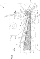
- each The downstream roll 76 has a radius of 15 mm, and the additional rollers 74 and 75 are also selected with a radius of 15 mm. More generally, the invention makes it possible to use downstream and additional rollers having radii of between 5 mm and 40 mm, preferably between 5 mm and 20 mm. As shown on the figure 3 each downstream roll 76 is disposed in the winding start configuration between the active compression roller 52 and the guide surface 37 of the horizontal belt 3. This arrangement is made possible by the restricted diameter of each downstream roll 76.
- the precompression surface 79 formed by the band 71 stretched against the rollers 74, 75 and 76 is a homogeneous surface, having a length l of the order of 90 mm in orthogonal projection on the guiding surface 37 of the horizontal carpet 3.
- the precompression surface 79 is thus able to exert a substantially homogeneous pressure force on a slice fibrous mattress length of the order of 90 mm, before entering the winding zone 10.
- the precompression mat 7 comprises a plurality of covers 72, where each cover 72 covers one of the strips 71 at the end of the precompression mat closest to the winding zone 10, while leaving uncovered the precompression surface 79 formed by this band 71. As shown in FIG. figure 6 , each cover 72 extends on the side 78 of the precompression mat opposite the horizontal belt 3, facing the corresponding downstream roller 76 without extending beyond the additional rollers 74 and 75.
- the angle ⁇ of inclination of the precompression surface 79 with respect to the guiding surface 37 is of the order of 10 °. More generally, the angle is advantageously between 5 ° and 15 °, preferably less than or equal to 10 °.
- the distance d 1 between the precompression pad 7 and the guiding surface 37 of the horizontal mat 3 is chosen to be minimum at each downstream roll 76. Thus, the desired compression ratio of the mat entering the winding zone is reached at less at the downstream roll of the precompression mat.
- the distance d 1 between the precompression surface 79 at the downstream roll 76 and the guide surface 37 of the first conveyor belt is adjustable and equal to the desired precompressed thickness of a fibrous mat entering the winding area.
- the position, at the beginning of winding, of the downstream roll 76 between the compression roller 52 and the guiding surface 37 of the first conveyor belt makes it possible to limit as much as possible the re-inflation of the mattress at the exit of the precompression conveyor 7.
- each winding device differs from the device of the first embodiment only in the structure of the downstream assembly of its precompression mat 7.
- the precompression mat 7 is devoid of additional rollers and the body 70 'extends to be juxtaposed with the series of downstream rollers 76.
- the pre-compression scrolling surface 79 is formed, facing the guide surface 37 of the horizontal carpet 3 by the band 71 stretched against the downstream assembly formed by the downstream end of the body 70 'and the downstream roller 76 which is juxtaposed therewith.
- the precompression pad 7 is devoid of both additional rolls and downstream rollers.
- the downstream end around which each of the strips 71 is wound is formed by a curved edge 761 of a thin plate 76 '("knife edge") which extends from the downstream end. of the body 70 in the direction of the winding zone 10.
- the precompression scrolling surface 79 is then formed, facing the guide surface 37 of the horizontal belt 3, by the belt 71 stretched against the downstream assembly formed by the flat portion 762 and the curved edge 761 of the plate 76 '.
- each curved edge 761, centered on a central axis X 761 has a radius of curvature of the order of 10 mm. More generally, the radius of curvature is preferably between 5 mm and 40 mm.
- the winding device 1 operates as follows.
- a fibrous mat 9, positioned on the horizontal mat 3, is driven together by the horizontal mat 3 and the precompression mat 7 towards the winding area 10.
- the mattress 9 is compressed between the guide surface 37 of the horizontal mat 3 and the face 77 of the precompression mat 7.
- the speed of circulation of the strip 71 of the precompression mat 7 by relative to the frame 2 is advantageously adjusted so that its component directed parallel to the direction F 1 of circulation of the guide surface 37 of the horizontal belt 3, that is to say its horizontal component in the example shown, is of the same meaning and same module as the speed of circulation of the guide surface 37 relative to the frame.
- a fibrous core is formed, which corresponds to a first turn of a fibrous roll.
- the contact pressure exerted by the compression roller 52 is controlled by means of the four jacks 6 and 8, so that the fibrous roll being formed remains substantially cylindrical.
- the precompression pad 7 is moved in the direction of the arrow F 5 of the figure 3 .
- the horizontal component of the speed of circulation of the band 71 increases as a function of the speed of the recoil of the precompression mat 7 so as to avoid shearing of the mattress 9.
- a winding device makes it possible to limit the friction exerted on a fibrous mat during its winding, and thus to limit the risk of damaging the mattress, even for high speeds. scroll of the mattress.
- a winder device thanks to the reduced dimensions of the downstream end of the precompression mat, has improved compactness, while maintaining a high compression rate of fibrous mat.
- the precompression mat may comprise a single band 71 and a single downstream end 76, 761.
- the precompression mat may also comprise a plurality of upstream rollers, instead of a single upstream roll 73, each upstream roll corresponding to one of the downstream ends and each band winding around an upstream roll and the corresponding downstream end.
- the number of additional rolls 74, 75 may be different from two, especially the precompression mat may comprise a number n ⁇ 1 of additional rolls, n being preferably equal to 1, 2 or 3.
- two pairs of actuators may be provided to move a conventional compression roll holder carrying a single compression roll, instead of two selectable compression rolls as previously described.
- a compression roller support carrying at least two selectable compression rollers may also be envisaged for a winding device having any precompression means, in particular different from the pre-compression scroll surface carpet 7, and means for displacement of the compression roll support, in particular different from the two pairs of actuators 6, 8.
Description
La présente invention a trait à un dispositif enrouleur pour la formation de rouleaux fibreux comprimés à partir de matelas fibreux souples et compressibles.The present invention relates to a winder device for forming fibrous rolls compressed from flexible and compressible fibrous mattresses.
En vue de réduire l'encombrement de matelas fibreux souples, il est connu de les enrouler sur eux-mêmes à l'état comprimé, ce qui permet d'obtenir des rouleaux de diamètre réduit. En particulier, il est classique d'enrouler sur eux-mêmes des matelas fibreux à base de fibres inorganiques, notamment de fibres de verre ou de roche, destinés à l'isolation thermique et/ou acoustique de bâtiments, véhicules ou machines. Ces matelas fibreux, qui ont généralement une masse volumique comprise entre 5 et 50 kg/m3, sont enroulés sur eux-mêmes avec des taux de compression élevés de manière à diminuer les coûts de transport et de stockage.In order to reduce the bulk of flexible fibrous mattresses, it is known to wrap them on themselves in the compressed state, which makes it possible to obtain rollers of reduced diameter. In particular, it is conventional to wind on themselves fibrous mattresses based on inorganic fibers, especially glass fibers or rock, for the thermal and / or acoustic insulation of buildings, vehicles or machines. These fibrous mats, which generally have a density of between 5 and 50 kg / m 3 , are wound on themselves with high compression ratios so as to reduce transport and storage costs.
L'opération d'enroulement d'un matelas fibreux doit s'effectuer dans des conditions contrôlées, afin de ne pas dépasser un taux de compression maximal admissible du matelas au-delà duquel il existe un risque de détérioration des fibres et du liant éventuel constituant le matelas. De préférence, l'opération d'enroulement est optimisée de sorte que le taux de compression est uniforme sur toute la longueur du matelas et ajusté pour ne pas dégrader les fibres et le liant. De cette façon, on assure à la fois que l'encombrement du matelas fibreux à l'état enroulé est minimisé et que, lors de son déroulement, le matelas fibreux retrouve son épaisseur et ses caractéristiques isolantes nominales.The operation of winding a fibrous mat must be carried out under controlled conditions, so as not to exceed a maximum permissible compression ratio of the mattress beyond which there is a risk of deterioration of the fibers and the binder, if any, constituting the mattress. Preferably, the winding operation is optimized so that the compression ratio is uniform over the entire length of the mattress and adjusted to not degrade the fibers and the binder. In this way, it is ensured at the same time that the bulk of the fibrous mat in the wound state is minimized and that, during its unwinding, the fibrous mat returns to its thickness and its nominal insulating characteristics.
A cet effet, l'invention a pour objet un dispositif enrouleur pour la formation de rouleaux fibreux à partir de matelas fibreux compressibles, comprenant :
- un premier tapis convoyeur et un deuxième tapis convoyeur ayant des surfaces de guidage qui forment un angle aigu entre elles,
- un rouleau mobile de compression disposé dans l'angle aigu entre les surfaces de guidage, le rouleau de compression et les surfaces de guidage délimitant une zone d'enroulement,
- un tapis mobile de précompression dont une face est en regard de la surface de guidage du premier tapis convoyeur et converge avec celle-ci en direction de la zone d'enroulement, le tapis de précompression comportant :
- ∘ un rouleau amont à son extrémité la plus éloignée de la zone d'enroulement,
- ∘ un ensemble aval à son extrémité la plus proche de la zone d'enroulement, l'ensemble aval ayant une extrémité avale incurvée, et
- ∘ une bande qui s'enroule autour du rouleau amont et de l'ensemble aval,
- a first conveyor belt and a second conveyor belt having guiding surfaces which form an acute angle between them,
- a movable compression roller disposed in the acute angle between the guide surfaces, the compression roller and the guide surfaces defining a winding zone,
- a moving precompression mat having one side facing the guide surface of the first conveyor belt and converging therewith towards the winding area, the precompression mat comprising:
- ∘ an upstream roller at its end farthest from the winding zone,
- A downstream assembly at its end closest to the winding zone, the downstream assembly having a curved downstream end, and
- ∘ a band that wraps around the upstream roller and the downstream assembly,
Dans le cadre de l'invention, on entend par élément de précompression tout élément qui assure, en association avec la surface de guidage du premier tapis convoyeur, une compression du matelas avant son entrée dans la zone d'enroulement.In the context of the invention, the term precompression element any element which ensures, in association with the guide surface of the first conveyor belt, compression of the mattress before entering the winding zone.
Grâce à l'invention, le taux de compression souhaité du matelas résulte d'un effort de pression exercé sur le matelas par la surface de précompression qui est l'élément de précompression le plus proche de la zone d'enroulement. Or, la surface de précompression est un élément de roulement, puisqu'elle est formée par la bande du tapis de précompression tendue et défilante contre l'ensemble aval. Dès lors, par rapport au cas où l'effort de pression est exercé sur le matelas par un élément de glissement, la friction à l'interface entre le matelas et la surface de précompression est fortement réduite, ce qui permet de mieux préserver les propriétés du matelas.Thanks to the invention, the desired compression ratio of the mattress results from a pressure force exerted on the mattress by the precompression surface which is the precompression element closest to the winding zone. However, the precompression surface is a rolling element, since it is formed by the band of the precompression mat taut and moving against the downstream assembly. Therefore, compared with the case where the pressure force is exerted on the mattress by a sliding element, the friction at the interface between the mattress and the precompression surface is greatly reduced, which allows better preservation of the properties. mattress.
De manière avantageuse, la surface de précompression formée par la bande tendue contre l'ensemble aval est une surface sensiblement plane apte à exercer selon toute son étendue un effort de pression homogène sur un matelas fibreux reçu entre la surface de guidage du premier tapis convoyeur et la surface de précompression. Au sens de l'invention, une surface sensiblement plane est une surface plate, sensiblement sans irrégularités par rapport à un plan moyen de la surface. Avec une telle surface de précompression sensiblement plane, on évite des variations du taux de compression, en particulier des alternances de compressions et de décompressions du matelas, qui seraient susceptibles de dégrader la structure du matelas. Cela contribue à préserver les propriétés du matelas.Advantageously, the precompression surface formed by the strip taut against the downstream assembly is a substantially planar surface capable of exerting over its entire extent a homogeneous pressure force on a fibrous mat received between the guide surface of the first conveyor belt and the precompression surface. Within the meaning of the invention, a substantially flat surface is a flat surface, substantially without irregularities with respect to an average plane of the surface. With such a substantially flat pre-compression surface, it avoids variations in the compression ratio, in particular alternating compressions and decompressions of the mattress, which would be likely to degrade the structure of the mattress. This helps preserve the properties of the mattress.
De manière avantageuse, l'ensemble aval du tapis de précompression a une longueur, en projection orthogonale sur la surface de guidage du premier tapis convoyeur, supérieure ou égale à 30 mm, de préférence supérieure ou égale à 80 mm. Ainsi, l'effort de précompression exercé sur un matelas fibreux avant son entrée dans la zone d'enroulement s'applique de manière homogène sur toute une tranche du matelas le long de l'ensemble aval, et pas seulement sur une portion réduite du matelas à l'extrémité avale du tapis de précompression. Il en résulte que, dans la zone avale du tapis de précompression où le taux de précompression appliqué au matelas est le plus élevé, la sollicitation en compression du matelas est répartie sur une plus grande surface. Cela limite le risque de détérioration du matelas qui pourrait intervenir dans le cas d'un effort de compression important appliqué au matelas de manière soudaine et localisée à l'extrémité avale du tapis de précompression.Advantageously, the downstream assembly of the precompression mat has a length, in orthogonal projection on the guide surface of the first conveyor belt, greater than or equal to 30 mm, preferably greater than or equal to 80 mm. Thus, the precompression force exerted on a fibrous mat before its entry into the winding zone applies homogeneously to a whole slice of the mattress along the downstream assembly, and not only to a reduced portion of the mattress at the downstream end of the precompression mat. As a result, in the downstream zone of the precompression mat where the precompression rate applied to the mattress is highest, the compressive stress of the mattress is distributed over a larger area. This limits the risk of deterioration of the mattress that could occur in the case of a significant compressive force applied to the mattress suddenly and located at the downstream end of the precompression mat.
Selon une caractéristique avantageuse, la distance entre le tapis de précompression et la surface de guidage du premier tapis convoyeur est minimale au niveau de l'extrémité avale. En particulier, au niveau de l'extrémité avale, la distance entre la surface de précompression et la surface de guidage du premier tapis convoyeur est égale à une épaisseur précomprimée souhaitée d'un matelas fibreux entrant dans la zone d'enroulement.According to an advantageous characteristic, the distance between the precompression mat and the guide surface of the first conveyor belt is minimal at the downstream end. In particular, at the downstream end, the distance between the precompression surface and the guide surface of the first conveyor belt is equal to a desired precompressed thickness of a fibrous mat entering the winding area.
Selon une autre caractéristique avantageuse, l'extrémité avale est disposée, lorsque le dispositif enrouleur est dans une configuration de début d'enroulement, entre le rouleau de compression et la surface de guidage du premier tapis convoyeur. Cette position de l'extrémité avale permet de limiter le plus possible le regonflement du matelas à la sortie du tapis de précompression.According to another advantageous characteristic, the downstream end is disposed, when the winder device is in a winding start configuration, between the compression roller and the guide surface of the first conveyor belt. This position of the downstream end makes it possible to limit as much as possible the re-inflation of the mattress at the exit of the precompression mat.
De préférence, la surface de précompression est inclinée selon un angle compris entre 5° et 15°, de préférence inférieur ou égal à 10°, par rapport à la surface de guidage du premier tapis convoyeur.Preferably, the precompression surface is inclined at an angle of between 5 ° and 15 °, preferably less than or equal to 10 °, with respect to the guide surface of the first conveyor belt.
Selon un aspect de l'invention, le tapis de précompression comporte un capot qui couvre la bande à l'extrémité du tapis de précompression la plus proche de la zone d'enroulement, tout en laissant la surface de précompression découverte. Ce capot permet d'éviter tout risque de passage du matelas entre le rouleau de compression et le tapis de précompression.According to one aspect of the invention, the precompression mat has a cover which covers the strip at the end of the precompression mat the closer to the winding zone, while leaving the precompression surface uncovered. This cover avoids any risk of passage of the mat between the compression roller and the precompression mat.
De préférence, l'extrémité avale incurvée du tapis de précompression a un rayon de courbure compris entre 5 mm et 40 mm, de préférence entre 5 mm et 20 mm. Un rayon de courbure faible de l'extrémité avale permet de positionner celle-ci au plus proche de la zone d'enroulement, entre le rouleau de compression et la surface de guidage du premier tapis convoyeur, de manière à limiter le plus possible le regonflement du matelas à la sortie du tapis de précompression, en particulier au début de l'enroulement.Preferably, the curved downstream end of the precompression mat has a radius of curvature of between 5 mm and 40 mm, preferably between 5 mm and 20 mm. A small radius of curvature of the downstream end allows the latter to be positioned as close as possible to the winding zone, between the compression roll and the guide surface of the first conveyor belt, so as to limit as much as possible the re-inflation. mattress at the exit of the precompression mat, in particular at the beginning of the winding.
De manière avantageuse, au cours d'une opération d'enroulement, la vitesse de circulation de la bande du tapis de précompression en direction de la zone d'enroulement a une composante parallèle à la vitesse de circulation de la surface de guidage du premier tapis convoyeur, qui est de même sens et même module que celle-ci. Un tel agencement réduit la friction à l'interface entre le matelas et la surface de précompression et limite le cisaillement du matelas.Advantageously, during a winding operation, the speed of circulation of the belt of the precompression belt towards the winding zone has a component parallel to the speed of circulation of the guide surface of the first belt. conveyor, which is in the same sense and same module as this one. Such an arrangement reduces friction at the interface between the mattress and the precompression surface and limits the shearing of the mattress.
Selon un aspect de l'invention, la bande du tapis de précompression circule autour du rouleau amont et de l'extrémité avale en étant entraînée par le rouleau amont.According to one aspect of the invention, the precompression carpet strip circulates around the upstream roll and the downstream end being driven by the upstream roll.
Dans un mode de réalisation, l'ensemble aval est une plaque munie d'une arête incurvée ("knife edge") en tant qu'extrémité avale.In one embodiment, the downstream assembly is a plate having a knife edge as a downstream end.
Dans un autre mode de réalisation, l'ensemble aval comprend un rouleau aval en tant qu'extrémité avale et un ensemble de n rouleaux additionnels, avec n≥1, qui ont chacun leur axe parallèle à l'axe du rouleau aval et qui sont juxtaposés les uns aux autres et au rouleau aval à l'intérieur de la bande de telle sorte que, en regard de la surface de guidage du premier tapis convoyeur, la bande tendue contre le ou chaque rouleau additionnel et le rouleau aval juxtaposés forme la surface défilante de précompression. La présence du rouleau aval et des rouleaux additionnels permet, par rapport au cas où une plaque munie d'une arête arrondie ("knife edge") sert à l'enroulement de la bande à l'extrémité avale du tapis de précompression, de réduire l'usure de la bande et donc d'augmenter sa durée de vie. Par ailleurs, dans la mesure où le rouleau aval et les rouleaux additionnels forment une série de rouleaux juxtaposés les uns aux autres et où la bande du tapis de précompression est tendue en appui contre cette série de rouleaux, l'effort de pression exercé sur le matelas par la surface de précompression est sensiblement uniforme le long de la surface. Cela contribue à préserver les propriétés du matelas. En particulier, si les rouleaux étaient disjoints, on pourrait observer une alternance de compressions et de décompressions du matelas entre les rouleaux, qui serait susceptible de dégrader la structure du matelas.In another embodiment, the downstream assembly comprises a downstream roll as a downstream end and a set of n additional rolls, with n ≥1, each having their axis parallel to the axis of the downstream roll and which are juxtaposed with each other and with the downstream roll inside the band so that, facing the guide surface of the first conveyor belt, the band stretched against the or each additional roller and the downstream roll juxtaposed forms the surface scrolling precompression. The presence of the downstream roll and additional rollers allows, in relation to the case where a plate provided with a rounded edge ("knife edge") is used for winding the band at the downstream end of the precompression mat, reduce the wear of the strip and therefore d increase its life. Furthermore, since the downstream roll and the additional rollers form a series of rollers juxtaposed with each other and where the band of the precompression belt is stretched against this series of rollers, the pressure force exerted on the Mattress by the precompression surface is substantially uniform along the surface. This helps preserve the properties of the mattress. In particular, if the rollers were disjoint, we could observe an alternation of compressions and decompressions of the mattress between the rollers, which would be likely to degrade the structure of the mattress.
De préférence, le rouleau aval et le ou chaque rouleau additionnel ont un rayon compris entre 5 mm et 40 mm, de préférence entre 5 mm et 20 mm.Preferably, the downstream roll and the or each additional roll have a radius of between 5 mm and 40 mm, preferably between 5 mm and 20 mm.
Selon un aspect de l'invention, le tapis de précompression comporte :
- un rouleau amont unique à son extrémité la plus éloignée de la zone d'enroulement ;
- une pluralité d'extrémités avales incurvées à son extrémité la plus proche de la zone d'enroulement, les extrémités avales incurvées étant positionnées dans le prolongement les unes des autres avec leurs axes centraux confondus et parallèles à l'axe du rouleau amont ; et
- une pluralité de bandes, chaque bande s'enroulant autour du rouleau amont et de l'une des extrémités avales.
- a single upstream roll at its end furthest from the winding zone;
- a plurality of downstream ends curved at its end closest to the winding zone, the curved down ends being positioned in the extension of each other with their central axes coinciding and parallel to the axis of the upstream roller; and
- a plurality of strips, each strip wrapping around the upstream roll and one of the downstream ends.
En variante, le rouleau amont unique peut être remplacé par une pluralité de rouleaux amont positionnés dans le prolongement les uns des autres avec leurs axes confondus, chaque rouleau amont correspondant à l'une des extrémités avales et chaque bande s'enroulant autour d'un rouleau amont et de l'extrémité avale correspondante.Alternatively, the single upstream roll can be replaced by a plurality of upstream rollers positioned in the extension of each other with their axes coincident, each upstream roll corresponding to one of the downstream ends and each band winding around a upstream roll and the corresponding downstream end.
Une structure du tapis de précompression à bandes parallèles telle que décrite ci-dessus permet de limiter les efforts exercés sur chacune des extrémités avales, et ainsi de réduire le plus possible les dimensions, en particulier le rayon de courbure, et donc l'encombrement de ces extrémités avales. Chaque extrémité avale de rayon de courbure réduit peut dès lors avancer davantage dans la zone d'enroulement entre le rouleau de compression et la surface de guidage du premier tapis convoyeur, en particulier en début d'enroulement. Cela contribue à limiter le regonflement du matelas à la sortie du tapis de précompression. De plus, en cas d'usure ou de casse de l'une des bandes, la bande détériorée peut être changée indépendamment des autres, ce qui facilite la maintenance du dispositif enrouleur.A structure of the precompression belt with parallel bands as described above makes it possible to limit the forces exerted on each of the downstream ends, and thus to reduce as much as possible the dimensions, particular the radius of curvature, and therefore the size of these downstream ends. Each downstream end of reduced radius of curvature can then further advance in the winding area between the compression roll and the guide surface of the first conveyor belt, especially at the beginning of winding. This helps to limit the re-inflation of the mattress at the exit of the precompression mat. In addition, in case of wear or breakage of one of the bands, the damaged band can be changed independently of others, which facilitates the maintenance of the retractor device.
Selon d'autres caractéristiques avantageuses, dans le cas où le tapis de précompression présente une structure à bandes parallèles telle que décrite ci-dessus :
- chaque extrémité avale est un rouleau aval et le tapis de précompression comporte, pour chaque rouleau aval et chaque bande correspondante, un ensemble de n rouleaux additionnels, avec n≥1, qui ont chacun leur axe parallèle à l'axe du rouleau aval et qui sont juxtaposés les uns aux autres et au rouleau aval à l'intérieur de la bande de telle sorte que, en regard de la surface de guidage du premier tapis convoyeur, la bande tendue contre le ou chaque rouleau additionnel et le rouleau aval juxtaposés forme une surface défilante de précompression ;
- le tapis de précompression comporte une pluralité de capots, chaque capot couvrant l'une des bandes à l'extrémité du tapis de précompression la plus proche de la zone d'enroulement, tout en laissant découverte la surface de précompression formée par cette bande.
- each downstream end is a downstream roll and the pre-compression mat comprises, for each downstream roll and each corresponding band, a set of n additional rollers, with n ≥1, each having their axis parallel to the axis of the downstream roll and which are juxtaposed with each other and with the downstream roll inside the band so that, facing the guide surface of the first conveyor belt, the band stretched against the or each additional roll and the downstream roll juxtaposed forms a moving surface of precompression;
- the precompression mat has a plurality of covers, each cover covering one of the strips at the end of the pre-compression mat closest to the winding area, while leaving uncovered the precompression surface formed by this strip.
Selon un aspect de l'invention, le dispositif comprend des moyens de déplacement en translation, au cours d'une opération d'enroulement, du tapis de précompression à l'écart du deuxième tapis convoyeur parallèlement à la direction de circulation de la surface de guidage du premier tapis convoyeur. De manière avantageuse, la vitesse de circulation de la bande du tapis de précompression autour du rouleau amont et de l'extrémité avale est alors ajustée, tout au long de l'opération d'enroulement, de telle sorte que la vitesse de circulation de la bande du tapis de précompression en direction de la zone d'enroulement garde sa composante parallèle à la vitesse de circulation de la surface de guidage du premier tapis convoyeur avec le même sens et le même module que celle-ci, malgré le mouvement de recul du tapis de précompression.According to one aspect of the invention, the device comprises means for translational movement, during a winding operation, of the precompression mat away from the second conveyor belt parallel to the direction of circulation of the surface of the guiding the first conveyor belt. Advantageously, the speed of circulation of the belt of the precompression belt around the upstream roller and the downstream end is then adjusted, throughout the winding operation, so that the speed of circulation of the carpet of precompression in the direction of the winding zone keeps its component parallel to the speed of circulation of the guide surface of the first conveyor belt with the same direction and the same module as the latter, despite the recoil movement of the precompression mat.
Selon une caractéristique qui peut être considérée indépendamment des caractéristiques listées précédemment, et notamment indépendamment de la forme des éléments de précompression du dispositif enrouleur, le rouleau de compression est monté rotatif sur un support et le dispositif enrouleur comprend des moyens de déplacement, au cours d'une opération d'enroulement, du support par rapport au bâti du dispositif, ces moyens comprenant deux paires d'actionneurs montés entre le support et le bâti du dispositif. Les deux actionneurs d'une paire peuvent être positionnés latéralement par rapport au support, chacun agissant à une extrémité latérale du support. Par rapport aux cas où l'actionnement du rouleau de compression est assuré par un bras unique muni d'un contrepoids, la mise en place de deux paires d'actionneurs, par exemple des vérins hydrauliques, électriques ou pneumatiques, qui agissent sur le rouleau de compression, permet de gagner latitude de réglage pour ajuster la position du rouleau de compression au cours d'une opération d'enroulement. En pratique, l'utilisation de quatre actionneurs permet d'obtenir toutes les trajectoires pour le rouleau de compression, tout en ayant un dispositif rigide, ce qui garantit un contrôle strict de la position du matelas.According to a feature that can be considered independently of the features listed above, and in particular regardless of the shape of the precompression elements of the winder device, the compression roller is rotatably mounted on a support and the winding device comprises displacement means, during a winding operation, the support relative to the frame of the device, these means comprising two pairs of actuators mounted between the support and the frame of the device. The two actuators of a pair may be positioned laterally with respect to the support, each acting at a lateral end of the support. Compared to cases where the actuation of the compression roller is ensured by a single arm provided with a counterweight, the establishment of two pairs of actuators, for example hydraulic cylinders, electric or pneumatic, which act on the roller compression, allows gaining adjustment latitude to adjust the position of the compression roll during a winding operation. In practice, the use of four actuators makes it possible to obtain all the trajectories for the compression roller, while having a rigid device, which guarantees a strict control of the position of the mattress.
Les moyens de déplacement du support peuvent être configurés pour positionner le rouleau de compression, au cours d'une opération d'enroulement, sur la bissectrice de l'angle aigu formé entre les surfaces de guidage des premier et deuxième tapis convoyeurs. Ainsi, l'agencement relatif des différents éléments du dispositif enrouleur présente une symétrie, ce qui simplifie le réglage et la programmation du dispositif. En pratique, au début d'une opération d'enroulement, le rouleau de compression se trouve au-dessus de la bissectrice afin de permettre la formation d'un noyau fibreux, c'est-à-dire d'une première spire du rouleau fibreux, puis il "rattrape" la bissectrice dans le cours de l'opération d'enroulement.The means for moving the support may be configured to position the compression roller, during a winding operation, on the bisector of the acute angle formed between the guide surfaces of the first and second conveyor belts. Thus, the relative arrangement of the various elements of the winding device has a symmetry, which simplifies the setting and programming of the device. In practice, at the beginning of a winding operation, the compression roller is above the bisector to allow the formation of a fibrous core, that is to say a first turn of the roll fibrous, then it "catches" the bisector in the course of the winding operation.
Selon une caractéristique qui peut être considérée indépendamment des caractéristiques listées précédemment, et notamment indépendamment de la forme des éléments de précompression du dispositif enrouleur, le dispositif enrouleur comprend au moins deux rouleaux de compression de diamètres différents qui sont montés rotatifs sur un même support avec leurs axes parallèles entre eux, le support étant apte à pivoter autour d'un axe parallèle aux axes des rouleaux de compression de manière à permettre la sélection de l'un des rouleaux de compression pour une opération d'enroulement d'un matelas fibreux.According to a characteristic that can be considered independently of the characteristics listed above, and in particular regardless of the shape of the precompression elements of the winding device, the winding device comprises at least two compression rollers of different diameters which are rotatably mounted on the same support with their axes parallel to each other, the support being able to pivot about an axis parallel to the axes of the compression rollers so as to allow the selection of one of the compression rollers for a winding operation of a fibrous mat.
Les caractéristiques et avantages de l'invention apparaîtront dans la description qui va suivre de plusieurs modes de réalisation d'un dispositif enrouleur selon l'invention, donnée uniquement à titre d'exemple et faite en se référant aux dessins annexés dans lesquels :
- la
figure 1 est une vue en perspective partielle d'un dispositif enrouleur conforme à un premier mode de réalisation de l'invention, le dispositif enrouleur étant dans une configuration de début d'enroulement ; - la
figure 2 est une vue de côté partielle du dispositif de lafigure 1 ; - la
figure 3 est une coupe à plus grande échelle de la zone d'enroulement du dispositif de lafigure 1 ; - la
figure 4 est une coupe analogue à lafigure 3 , le dispositif enrouleur étant dans une configuration ultérieure d'enroulement proche de la fin de l'enroulement ; - la
figure 5 est une vue en perspective selon la flèche V de lafigure 1 ; - la
figure 6 est une coupe à plus grande échelle selon le plan VI de lafigure 5 ; - la
figure 7 est une coupe analogue à lafigure 6 pour un dispositif enrouleur conforme à une deuxième mode de réalisation de l'invention ; et - la
figure 8 est une coupe analogue à lafigure 6 pour un dispositif enrouleur conforme à une troisième mode de réalisation de l'invention.
- the
figure 1 is a partial perspective view of a winder device according to a first embodiment of the invention, the winder device being in a winding start configuration; - the
figure 2 is a partial side view of the device of thefigure 1 ; - the
figure 3 is a larger-scale section of the winding area of the device of thefigure 1 ; - the
figure 4 is a cut similar to thefigure 3 , the retractor device being in a subsequent winding configuration close to the end of the winding; - the
figure 5 is a perspective view along arrow V of thefigure 1 ; - the
figure 6 is a larger scale section according to plan VI of thefigure 5 ; - the
figure 7 is a cut similar to thefigure 6 for a retractor device according to a second embodiment of the invention; and - the
figure 8 is a cut similar to thefigure 6 for a retractor device according to a third embodiment of the invention.
Dans un souci de clarté, certains éléments du dispositif enrouleur ont été représentés de manière schématique sur les
Le dispositif enrouleur 1 représenté sur les figures est destiné à l'enroulement de matelas fibreux souples et compressibles, en particulier de matelas fibreux à propriétés isolantes constitués à base de fibres inorganiques telles que des fibres de verre ou de roche. Le dispositif 1 comprend un bâti 2, qui supporte un tapis convoyeur horizontal 3. Le tapis horizontal 3 comporte une bande sans fin 31 qui s'enroule autour de deux rouleaux 33 et 35 d'axes parallèles et horizontaux. On note 37 la surface supérieure du tapis horizontal 3, qui est une surface de guidage destinée à recevoir et guider un matelas fibreux 9 dans le sens de la flèche F1 de la
Le dispositif 1 comprend également un tapis convoyeur dorsal 4 comportant une bande sans fin 41 qui s'enroule autour de deux rouleaux 43 et 45 d'axes parallèles et horizontaux. On note 47 la surface du tapis dorsal 4 qui est dirigée vers la surface 37 du tapis horizontal. La surface 47 est une surface de guidage destinée à recevoir et guider un matelas fibreux 9 dans le sens de la flèche F2 de la
Le dispositif 1 comprend par ailleurs un ensemble de compression 5, comportant deux rouleaux de compression 52 et 54 montés sur un même support 51. Les rouleaux 52 et 54 présentent des diamètres différents, respectivement un diamètre plus faible pour le rouleau 52, par exemple de l'ordre de 125 mm, et un diamètre plus élevé pour le rouleau 54, par exemple de l'ordre de 190 mm. Les rouleaux 52 et 54 sont montés rotatifs sur le support 51 avec leurs axes X52 et X54 parallèles et horizontaux, perpendiculairement à la direction F1 d'avancée du matelas. De plus, le support 51 est prévu pour pivoter autour d'un axe X51 parallèle aux axes X52 et X54 des deux rouleaux de compression, de manière à permettre la sélection de l'un des rouleaux de compression 52, 54 pour une opération d'enroulement d'un matelas fibreux. Sur les figures, c'est le rouleau de compression 52 qui a été sélectionné pour être actif lors de l'opération d'enroulement. Au cours d'une opération d'enroulement, le rouleau de compression sélectionné est entraîné en rotation autour de son axe de rotation X52 ou X54, dans le sens montré par la flèche F3 de la
En pratique, les deux rouleaux de compression 52 et 54 montés sur le même support 51 offrent la possibilité de choisir le rouleau de compression le mieux adapté en fonction des caractéristiques du matelas fibreux à enrouler, notamment en vue de préserver la qualité du matelas en début d'enroulement. En effet, au début d'une opération d'enroulement, le matelas peut se plier et se comprimer localement de manière incontrôlée dans la zone d'enroulement 10, ce qui peut endommager le matelas ou son surfaçage et engendrer des variations de reprise d'épaisseur. La partie de matelas affectée est d'autant plus courte que le diamètre du rouleau de compression est faible. Toutefois, plus le diamètre du rouleau de compression est faible, plus grand est le risque de fendre la tranche avant du matelas lors de son retournement en phase de formation du noyau. Pour un matelas épais, la longueur de matelas qui forme le noyau est faible, de sorte que l'utilisation du rouleau de compression de diamètre plus élevé est acceptable. Au contraire, pour un matelas plus mince, il est préférable d'utiliser le rouleau de compression de diamètre plus faible.In practice, the two
Le support 51 des rouleaux de compression est relié au bâti 2 du dispositif par l'intermédiaire de deux paires de vérins hydrauliques 6, 8 qui sont configurés pour déplacer le support 51, et les rouleaux de compression qui en sont solidaires, au cours d'une opération d'enroulement. Ainsi, la position du rouleau de compression 52 ou 54 qui est actif au cours de l'opération d'enroulement est réglable, et le rouleau de compression peut s'éloigner de la surface de guidage 37 du tapis horizontal 3 au fur et à mesure de l'augmentation du diamètre du rouleau fibreux résultant de l'enroulement du matelas. Comme visible sur la
Le dispositif 1 comprend également un troisième tapis convoyeur 7, dit tapis de précompression, qui est disposé au-dessus du tapis horizontal 3 de sorte que sa face 77 positionnée en regard de la surface de guidage 37 converge avec celle-ci en direction de la zone d'enroulement 10. Le tapis de précompression 7 est prévu pour assurer une précompression du matelas fibreux à un taux de compression souhaité avant son entrée dans la zone d'enroulement 10. Comme montré sur les
Dans le premier mode de réalisation représenté sur les
Comme bien visible sur les
De manière avantageuse, la structure du tapis de précompression 7 comprenant plusieurs bandes 71 parallèles permet de limiter les efforts exercés sur chacun des rouleaux avals 76, et ainsi de réduire le plus possible le diamètre de ces rouleaux 76. Dans ce mode de réalisation, chaque rouleau aval 76 a un rayon de 15 mm, et les rouleaux additionnels 74 et 75 sont choisis également avec un rayon de 15 mm. De manière plus générale, l'invention permet d'utiliser des rouleaux avals et additionnels ayant des rayons compris entre 5 mm et 40 mm, de préférence entre 5 mm et 20 mm. Tel que montré sur la
La surface de précompression 79 formée par la bande 71 tendue contre les rouleaux 74, 75 et 76 est une surface homogène, présentant une longueur ℓ de l'ordre de 90 mm en projection orthogonale sur la surface de guidage 37 du tapis horizontal 3. La surface de précompression 79 est ainsi apte à exercer un effort de pression sensiblement homogène sur une tranche de matelas fibreux de longueur de l'ordre de 90 mm, avant son entrée dans la zone d'enroulement 10.The
Afin d'éviter tout risque d'engouffrement d'un matelas fibreux dans l'espace intermédiaire défini entre le rouleau de compression actif 52 et les bandes 71, le tapis de précompression 7 comporte une pluralité de capots 72, où chaque capot 72 couvre l'une des bandes 71 à l'extrémité du tapis de précompression la plus proche de la zone d'enroulement 10, tout en laissant découverte la surface de précompression 79 formée par cette bande 71. Comme montré sur la
L'angle β d'inclinaison de la surface de précompression 79 par rapport à la surface de guidage 37 est de l'ordre de 10°. De manière plus générale, l'angle est avantageusement compris entre 5° et 15°, de préférence inférieur ou égal à 10°. La distance d1 entre le tapis de précompression 7 et la surface de guidage 37 du tapis horizontal 3 est choisie minimale au niveau de chaque rouleau aval 76. Ainsi, le taux de compression souhaité du matelas entrant dans la zone d'enroulement est atteint au moins au niveau du rouleau aval du tapis de précompression. La distance d1 entre la surface de précompression 79 au niveau du rouleau aval 76 et la surface de guidage 37 du premier tapis convoyeur est ajustable et égale à l'épaisseur précomprimée souhaitée d'un matelas fibreux entrant dans la zone d'enroulement. La position, en début d'enroulement, du rouleau aval 76 entre le rouleau de compression 52 et la surface de guidage 37 du premier tapis convoyeur permet de limiter le plus possible le regonflement du matelas à la sortie du convoyeur de précompression 7.The angle β of inclination of the
Dans les deuxième et troisième modes de réalisation représentés sur les
En particulier, sur la
Sur la
Pour les trois modes de réalisation décrits précédemment, le dispositif enrouleur 1 fonctionne de la façon suivante.For the three embodiments described above, the winding device 1 operates as follows.
Un matelas fibreux 9, positionné sur le tapis horizontal 3, est entraîné conjointement par le tapis horizontal 3 et par le tapis de précompression 7 en direction de la zone d'enroulement 10. Comme montré sur la
Dans la zone d'enroulement 10, grâce à l'entraînement conjoint du tapis horizontal 3, du tapis dorsal 4 et du rouleau de compression 52, un noyau fibreux se forme, qui correspond à une première spire d'un rouleau fibreux. Au cours de l'enroulement, la pression de contact exercée par le rouleau de compression 52 est contrôlée à l'aide des quatre vérins 6 et 8, de sorte que le rouleau fibreux en cours de formation reste sensiblement cylindrique.In the winding
À mesure que l'enroulement se poursuit et que le diamètre du rouleau fibreux augmente, le tapis de précompression 7 est déplacé dans le sens de la flèche F5 de la
Comme il ressort de la description qui précède, un dispositif enrouleur conforme à l'invention permet de limiter la friction exercée sur un matelas fibreux au cours de son enroulement, et donc de limiter les risques d'endommagement du matelas, même pour des vitesses élevées de défilement du matelas. De plus, grâce aux dimensions réduites de l'extrémité avale du tapis de précompression, un dispositif enrouleur selon l'invention présente une compacité améliorée, tout en maintenant un fort taux de compression de matelas fibreux.As is apparent from the foregoing description, a winding device according to the invention makes it possible to limit the friction exerted on a fibrous mat during its winding, and thus to limit the risk of damaging the mattress, even for high speeds. scroll of the mattress. In addition, thanks to the reduced dimensions of the downstream end of the precompression mat, a winder device according to the invention has improved compactness, while maintaining a high compression rate of fibrous mat.
L'invention n'est pas limitée aux exemples décrits et représentés.The invention is not limited to the examples described and shown.
En particulier, dans le cadre de l'invention, le tapis de précompression peut comporter une seule bande 71 et une seule extrémité avale 76, 761. Dans le cas où il comporte une pluralité de bandes 71 et d'extrémités avales 76, 761, le tapis de précompression peut également comporter une pluralité de rouleaux amont, au lieu d'un rouleau amont 73 unique, chaque rouleau amont correspondant à l'une des extrémités avales et chaque bande s'enroulant autour d'un rouleau amont et de l'extrémité avale correspondante. Par ailleurs, dans le premier mode de réalisation, le nombre des rouleaux additionnels 74, 75 peut être différent de deux, notamment le tapis de précompression peut comprendre un nombre n ≥1 de rouleaux additionnels, n étant de préférence égal à 1, 2 ou 3.In particular, in the context of the invention, the precompression mat may comprise a
La mise en place de deux paires d'actionneurs montés entre le support et le bâti du dispositif pour déplacer le support 51 de rouleau de compression peut également avoir lieu dans le cadre d'un dispositif enrouleur présentant des moyens de précompression quelconques, en particulier différents du tapis 7 à surface défilante de précompression tel que décrit précédemment.The establishment of two pairs of actuators mounted between the support and the frame of the device for moving the
De la même façon, la mise en place de deux paires d'actionneurs peut avoir lieu pour déplacer un support classique de rouleau de compression portant un seul rouleau de compression, au lieu de deux rouleaux de compression sélectionnables comme décrit précédemment.Similarly, two pairs of actuators may be provided to move a conventional compression roll holder carrying a single compression roll, instead of two selectable compression rolls as previously described.
L'utilisation d'un support de rouleau de compression portant au moins deux rouleaux de compression sélectionnables peut également être envisagée pour un dispositif enrouleur présentant des moyens de précompression quelconques, en particulier différents du tapis 7 à surface défilante de précompression, et des moyens de déplacement du support de rouleau de compression quelconques, en particulier différents des deux paires d'actionneurs 6, 8.The use of a compression roller support carrying at least two selectable compression rollers may also be envisaged for a winding device having any precompression means, in particular different from the pre-compression
Claims (20)
- A winding device (1) for the formation of fibrous rolls from compressible fibrous mats (9), comprising:- a first conveyor (3) and a second conveyor (4) with guide surfaces (37, 47) which form an acute angle (α) between one another;- a movable compression roller (52, 54) which is disposed in the acute angle (α) between the guide surfaces (37, 47), with the compression roller (52, 54) and the guide surfaces (37, 47) delimiting a winding area (10);- a movable pre-compression conveyor (7), a face (77) of which faces the guide surface (37) of the first conveyor (3), and converges with the latter toward the winding area (10), the pre-compression conveyor (7) comprising:characterized in that, facing the guide surface (37) of the first conveyor (3), the belt (71), which is held under tension against the downstream assembly (74, 75, 76; 70', 76; 76'), forms a circulating pre-compression surface (79) for pre-compression of a fibrous mat to be wound, this pre-compression surface (79) being the pre-compression element which is closest to the winding area (10).∘ an upstream roller (73) at its end which is furthest from the winding area;∘ a downstream assembly (74, 75, 76; 70', 76; 76') at its end which is closest to the winding area, the downstream assembly having a curved downstream end (76; 761); and∘ a belt (71) which is wound around the upstream roller (73) and the downstream assembly (74, 75, 76; 70', 76; 76'),
- The winding device as claimed in claim 1, characterized in that the pre-compression surface (79) formed by the belt (71) held under tension against the downstream assembly (74, 75, 76; 70', 76; 76') is a substantially flat surface which can exert a homogenous pressure force on a fibrous mat to be wound.
- The winding device as claimed in either of claims 1 and 2, characterized in that the downstream assembly (74, 75, 76; 70', 76; 76') has a length (ℓ), in normal projection on the guide surface (37) of the first conveyor (3), of 30 mm or more, preferably 80 mm or more.
- The winding device as claimed in any one of the preceding claims, characterized in that the distance between the pre-compression conveyor (7) and the guide surface (37) of the first conveyor is minimal (d1) at the downstream end (76; 761).
- The winding device as claimed in any one of the preceding claims, characterized in that, when the winding device (1) is in a winding start configuration, the downstream end (76; 761) is disposed between the compression roller (52, 54) and the guide surface (37) of the first conveyor.
- The winding device as claimed in any one of the preceding claims, characterized in that the pre-compression conveyor (7) comprises a cover (72) which covers the belt (71) at the end of the pre-compression conveyor which is closest to the winding area (10), while leaving the pre-compression surface (79) uncovered.
- The winding device as claimed in any one of the preceding claims, characterized in that the downstream end (76; 761) has a radius of curvature of between 5 mm and 40 mm, preferably between 5 mm and 20 mm.
- The winding device as claimed in any one of the preceding claims, characterized in that, during a winding operation, the speed of the belt (71) of the pre-compression conveyor (7) toward the winding area (10) has a component parallel to the speed of the guide surface (37) of the first conveyor (3), which component is of same direction and same modulus as the latter.
- The winding device as claimed in any one of the preceding claims, characterized in that the belt (71) of the pre-compression conveyor (7) circulates around the upstream roller (73) and the downstream end (76; 761), while being driven by the upstream roller (73).
- The winding device as claimed in any one of the preceding claims, characterized in that the downstream assembly comprises a plate (76') provided with a curved ridge (761) as a downstream end.
- The winding device as claimed in any one of claims 1 to 9, characterized in that the downstream assembly comprises a roller (76) as a downstream end and an assembly of n additional rollers (74, 75), where n≥1, which each have their axis (X74, X75) parallel to the axis (X76) of the downstream roller (76), and are juxtaposed relative to one another and to the downstream roller (76) in the interior of the belt (71), such that, facing the guide surface (37) of the first conveyor (3), the belt (71), which is held under tension against the or each additional roller and the downstream roller which are juxtaposed, forms said circulating pre-compression surface (79).
- The winding device as claimed in claim 11, characterized in that the or each downstream roller (76) and the or each additional roller (74, 75) has a radius of between 5 mm and 40 mm, preferably between 5 mm and 20 mm.
- The winding device as claimed in any one of the preceding claims, characterized in that the pre-compression conveyor (7) comprises:- a single upstream roller (73) at its end which is furthest from the winding area (10);- a plurality of curved downstream ends (76; 761) at its end which is closest to the winding area (10), the curved downstream ends (76; 761) being positioned aligned with each other, with their central axes (X76; X761) parallel to the axis (X73) of the upstream roller (73); and- a plurality of belts (71), each belt (71) being wound around the upstream roller (73) and one of the downstream ends (76; 761).
- The winding device as claimed in claim 13, characterized in that the single upstream roller is replaced by a plurality of upstream rollers positioned aligned with each other with their axes being coincident, each upstream roller corresponding to one of the downstream ends (76; 761), and each belt (71) being wound around an upstream roller and the corresponding downstream end.
- The winding device as claimed in either of claims 13 and 14, characterized in that each downstream end is a roller (76), and the pre-compression conveyor (7) comprises, for each downstream roller (76) and each corresponding belt (71), an assembly of n additional rollers (74, 75), where n≥1, which each have their axis (X74, X75) parallel to the axis (X76) of the downstream roller (76), and are juxtaposed relative to one another and to the downstream roller (76) in the interior of the belt (71), such that, facing the guide surface (37) of the first conveyor (3), the belt (71), which is held under tension against the or each additional roller and the downstream roller which are juxtaposed, forms a circulating pre-compression surface (79).
- The winding device as claimed in any one of claims 13 to 15, characterized in that the pre-compression conveyor (7) comprises a plurality of covers (72), each cover (72) covering one of the belts (71) at the end of the pre-compression conveyor which is closest to the winding area (10), while leaving the pre-compression surface (79) formed by this belt (71) uncovered.
- The winding device as claimed in any one of the preceding claims, characterized in that it comprises means for displacement in translation, during a winding operation, of the pre-compression conveyor (7) away from the second conveyor (4) parallel to the direction of circulation of the guide surface (37) of the first conveyor (3).
- The winding device as claimed in any one of the preceding claims, characterized in that the compression roller (52, 54) is fitted such as to rotate on a support (51), and the device comprises means (6, 8) for displacement, during a winding operation, of the support (51) relative to the frame (2) of the device, these means comprising two pairs of actuators (6, 8) which are fitted between the support (51) and the frame (2).
- The winding device as claimed in claim 18, characterized in that the means (6, 8) for displacement of the support (51) are configured in order to position the compression roller (52, 54), during a winding operation, on the bisectrix of the acute angle (α) formed between the guide surfaces (37, 47) of the first (3) and second (4) conveyors.
- The winding device as claimed in any one of the preceding claims, characterized in that it comprises at least two compression rollers (52, 54) with different diameters, which are fitted such as to rotate on the same support (51), with their axes (X52, X54) parallel to one another, the support (51) being able to pivot around an axis (X51) parallel to the axes (X52, X54) of the two compression rollers (52, 54) such as to permit the selection of one of the compression rollers (52, 54) for a winding operation.
Priority Applications (1)
| Application Number | Priority Date | Filing Date | Title |
|---|---|---|---|
| PL13728496T PL2855312T3 (en) | 2012-06-04 | 2013-05-27 | Winding device |
Applications Claiming Priority (2)
| Application Number | Priority Date | Filing Date | Title |
|---|---|---|---|
| FR1255183A FR2991301B1 (en) | 2012-06-04 | 2012-06-04 | ROLLER DEVICE |
| PCT/FR2013/051162 WO2013182777A1 (en) | 2012-06-04 | 2013-05-27 | Winding device |
Publications (2)
| Publication Number | Publication Date |
|---|---|
| EP2855312A1 EP2855312A1 (en) | 2015-04-08 |
| EP2855312B1 true EP2855312B1 (en) | 2018-02-28 |
Family
ID=46826697
Family Applications (1)
| Application Number | Title | Priority Date | Filing Date |
|---|---|---|---|
| EP13728496.4A Active EP2855312B1 (en) | 2012-06-04 | 2013-05-27 | Winding device |
Country Status (12)
| Country | Link |
|---|---|
| US (1) | US9701504B2 (en) |
| EP (1) | EP2855312B1 (en) |
| JP (1) | JP6228192B2 (en) |
| CN (1) | CN104520217B (en) |
| AU (1) | AU2013273359B2 (en) |
| DK (1) | DK2855312T3 (en) |
| ES (1) | ES2669558T3 (en) |
| FR (1) | FR2991301B1 (en) |
| IN (1) | IN2014DN10287A (en) |
| PL (1) | PL2855312T3 (en) |
| RU (1) | RU2629976C2 (en) |
| WO (1) | WO2013182777A1 (en) |
Families Citing this family (4)
| Publication number | Priority date | Publication date | Assignee | Title |
|---|---|---|---|---|
| US9868605B2 (en) * | 2014-02-12 | 2018-01-16 | Andrew L. Bishop | Geotextile rolling apparatus |
| CN104911941B (en) * | 2015-05-19 | 2017-03-08 | 福建汇利丰环保科技有限公司 | A kind of can automatically web-like collect pneumatic mortar machine output pulp material receiving mechanism |
| CN108782654A (en) * | 2018-06-14 | 2018-11-13 | 广州浩胜弘裕机械设备有限公司 | A kind of cake volume layer machine and its working method |
| US11787655B2 (en) | 2020-09-28 | 2023-10-17 | C3 Corporation | Variable roll cage machine and process |
Family Cites Families (11)
| Publication number | Priority date | Publication date | Assignee | Title |
|---|---|---|---|---|
| FR2553744B1 (en) | 1983-10-21 | 1986-03-28 | Saint Gobain Isover | COMPRESSION COILER |
| SU1594095A1 (en) * | 1988-05-03 | 1990-09-23 | Специализированный Трест "Белтеплоизоляция" | Arrangement for winding strip material into coil |
| FR2685904A1 (en) * | 1992-01-07 | 1993-07-09 | Saint Gobain Isover | COMPRESSED FIBROUS MATTRESS ROLL, METHOD AND DEVICE FOR OBTAINING THE SAME. |
| US5305963A (en) * | 1992-12-03 | 1994-04-26 | Schuller International, Inc. | Method and apparatus for forming rolls from strips of compressible material |
| FR2731687B1 (en) * | 1995-03-17 | 1997-04-25 | Tictor Sa | REEL DEVICE FOR FORMING A COMPRESSED FIBROUS ROLL |
| DE29604901U1 (en) * | 1996-03-16 | 1996-05-15 | Kaibel & Sieber Gmbh | Device for winding a web of compressible material |
| ZA981514B (en) * | 1997-03-07 | 1998-08-28 | Saint Gobain Isover | Winding machine for fibrous mats |
| EP0941952A1 (en) * | 1998-03-09 | 1999-09-15 | Techint Compagnia Tecnica Internazionale S.P.A. | An apparatus for rolling up compressible fibrous materials |
| EP0949172B1 (en) * | 1998-04-07 | 2001-03-21 | TECHINT COMPAGNIA TECNICA INTERNAZIONALE S.p.A. | Improved apparatus for rolling up compressible fibrous materials |
| FI122646B (en) * | 2007-11-28 | 2012-05-15 | Paroc Oy Ab | Method and apparatus for forming mineral wool rolls |
| JP5747636B2 (en) * | 2010-06-03 | 2015-07-15 | セントラル硝子株式会社 | Mat winding device |
-
2012
- 2012-06-04 FR FR1255183A patent/FR2991301B1/en not_active Expired - Fee Related
-
2013
- 2013-05-27 DK DK13728496.4T patent/DK2855312T3/en active
- 2013-05-27 EP EP13728496.4A patent/EP2855312B1/en active Active
- 2013-05-27 IN IN10287DEN2014 patent/IN2014DN10287A/en unknown
- 2013-05-27 AU AU2013273359A patent/AU2013273359B2/en active Active
- 2013-05-27 JP JP2015515563A patent/JP6228192B2/en active Active
- 2013-05-27 WO PCT/FR2013/051162 patent/WO2013182777A1/en active Application Filing
- 2013-05-27 RU RU2014153635A patent/RU2629976C2/en active
- 2013-05-27 US US14/405,506 patent/US9701504B2/en active Active
- 2013-05-27 ES ES13728496.4T patent/ES2669558T3/en active Active
- 2013-05-27 PL PL13728496T patent/PL2855312T3/en unknown
- 2013-05-27 CN CN201380041506.0A patent/CN104520217B/en active Active
Also Published As
| Publication number | Publication date |
|---|---|
| DK2855312T3 (en) | 2018-06-14 |
| CN104520217A (en) | 2015-04-15 |
| RU2014153635A (en) | 2016-07-27 |
| US20150166287A1 (en) | 2015-06-18 |
| FR2991301B1 (en) | 2014-05-23 |
| PL2855312T3 (en) | 2018-07-31 |
| RU2629976C2 (en) | 2017-09-05 |
| US9701504B2 (en) | 2017-07-11 |
| FR2991301A1 (en) | 2013-12-06 |
| AU2013273359B2 (en) | 2017-06-29 |
| ES2669558T3 (en) | 2018-05-28 |
| AU2013273359A1 (en) | 2015-01-29 |
| WO2013182777A1 (en) | 2013-12-12 |
| IN2014DN10287A (en) | 2015-08-07 |
| EP2855312A1 (en) | 2015-04-08 |
| JP6228192B2 (en) | 2017-11-08 |
| JP2015523287A (en) | 2015-08-13 |
| CN104520217B (en) | 2018-02-23 |
Similar Documents
| Publication | Publication Date | Title |
|---|---|---|
| EP2855312B1 (en) | Winding device | |
| EP0140785B1 (en) | Winder with controlled compression | |
| EP0040145A1 (en) | Apparatus for cutting long fibres, particularly glass fibres | |
| EP0238393B1 (en) | Compressing winding apparatus | |
| FR2620117A1 (en) | DIVIDING AND REENROUTING STRIP MACHINES | |
| EP0734985A1 (en) | Winding device for forming a compressed fibrous roll | |
| FR2846643A1 (en) | Reel for plastics film production has cylinder with spaced supports to control cylinder deformation | |
| CH685126A5 (en) | Crimper. | |
| WO1998040297A1 (en) | Rolling machine for fibrous mattresses | |
| EP1711423B1 (en) | Double driving roll winding device for continuous rolling machine with controlled application load of the driving rolls | |
| EP0035114B1 (en) | Machine for compressing straw, hay and the like into balls | |
| EP1552892A1 (en) | Machine for straightening metal bands | |
| EP0935505A1 (en) | Spiral winder | |
| EP1322807B1 (en) | Method and device for making mineral fibre felts | |
| EP0560662B1 (en) | Method and installation for rolling a metal plate | |
| FR2793382A1 (en) | Device facilitating formation of core of ball in round ball press comprises three parallel rollers mounted on freely rotating frame and fixed at one end to balancing pole | |
| FR2524253A1 (en) | Machine for unrolling spiral wound hay bale - uses converging rollers to hold bale with free end outer whorl between traction drum and conveyor | |
| EP1867232B1 (en) | Device for moulding dough pieces. | |
| BE1009088A5 (en) | Process for veneers guidance. | |
| FR2679152A1 (en) | Machine for distributing compressed products | |
| FR2962427A1 (en) | Paper tape unwinding method, involves applying resistive torque on reel, where torque is inversely proportional to weight of reel during unwinding of paper tape, and exerting constant traction on tape during unwinding of tape | |
| FR2725877A1 (en) | Sausage twister suitable for wide range of fillings and skins | |
| BE557865A (en) | ||
| FR2922411A1 (en) | Pulley's driving controlling method for hauling device, involves reducing speeds of tow and intermediary pulleys based on speed of input pulley in progressive manner as input pulley is moved away in scrolling direction of fishing line | |
| CH294642A (en) | Machine for winding a sheet of textile fibers. |
Legal Events
| Date | Code | Title | Description |
|---|---|---|---|
| PUAI | Public reference made under article 153(3) epc to a published international application that has entered the european phase |
Free format text: ORIGINAL CODE: 0009012 |
|
| 17P | Request for examination filed |
Effective date: 20150105 |
|
| AK | Designated contracting states |
Kind code of ref document: A1 Designated state(s): AL AT BE BG CH CY CZ DE DK EE ES FI FR GB GR HR HU IE IS IT LI LT LU LV MC MK MT NL NO PL PT RO RS SE SI SK SM TR |
|
| AX | Request for extension of the european patent |
Extension state: BA ME |
|
| DAX | Request for extension of the european patent (deleted) | ||
| GRAP | Despatch of communication of intention to grant a patent |
Free format text: ORIGINAL CODE: EPIDOSNIGR1 |
|
| INTG | Intention to grant announced |
Effective date: 20170914 |
|
| GRAS | Grant fee paid |
Free format text: ORIGINAL CODE: EPIDOSNIGR3 |
|
| GRAA | (expected) grant |
Free format text: ORIGINAL CODE: 0009210 |
|
| AK | Designated contracting states |
Kind code of ref document: B1 Designated state(s): AL AT BE BG CH CY CZ DE DK EE ES FI FR GB GR HR HU IE IS IT LI LT LU LV MC MK MT NL NO PL PT RO RS SE SI SK SM TR |
|
| REG | Reference to a national code |
Ref country code: GB Ref legal event code: FG4D Free format text: NOT ENGLISH Ref country code: CH Ref legal event code: EP |
|
| REG | Reference to a national code |
Ref country code: AT Ref legal event code: REF Ref document number: 973855 Country of ref document: AT Kind code of ref document: T Effective date: 20180315 |
|
| REG | Reference to a national code |
Ref country code: IE Ref legal event code: FG4D Free format text: LANGUAGE OF EP DOCUMENT: FRENCH |
|
| REG | Reference to a national code |
Ref country code: DE Ref legal event code: R096 Ref document number: 602013033697 Country of ref document: DE |
|
| REG | Reference to a national code |
Ref country code: SE Ref legal event code: TRGR |
|
| REG | Reference to a national code |
Ref country code: FR Ref legal event code: PLFP Year of fee payment: 6 |
|
| REG | Reference to a national code |
Ref country code: RO Ref legal event code: EPE |
|
| REG | Reference to a national code |
Ref country code: ES Ref legal event code: FG2A Ref document number: 2669558 Country of ref document: ES Kind code of ref document: T3 Effective date: 20180528 |
|
| REG | Reference to a national code |
Ref country code: NL Ref legal event code: FP |
|
| REG | Reference to a national code |
Ref country code: DK Ref legal event code: T3 Effective date: 20180607 |
|
| REG | Reference to a national code |
Ref country code: LT Ref legal event code: MG4D |
|
| REG | Reference to a national code |
Ref country code: AT Ref legal event code: MK05 Ref document number: 973855 Country of ref document: AT Kind code of ref document: T Effective date: 20180228 |
|
| PG25 | Lapsed in a contracting state [announced via postgrant information from national office to epo] |
Ref country code: CY Free format text: LAPSE BECAUSE OF FAILURE TO SUBMIT A TRANSLATION OF THE DESCRIPTION OR TO PAY THE FEE WITHIN THE PRESCRIBED TIME-LIMIT Effective date: 20180228 Ref country code: NO Free format text: LAPSE BECAUSE OF FAILURE TO SUBMIT A TRANSLATION OF THE DESCRIPTION OR TO PAY THE FEE WITHIN THE PRESCRIBED TIME-LIMIT Effective date: 20180528 Ref country code: HR Free format text: LAPSE BECAUSE OF FAILURE TO SUBMIT A TRANSLATION OF THE DESCRIPTION OR TO PAY THE FEE WITHIN THE PRESCRIBED TIME-LIMIT Effective date: 20180228 Ref country code: LT Free format text: LAPSE BECAUSE OF FAILURE TO SUBMIT A TRANSLATION OF THE DESCRIPTION OR TO PAY THE FEE WITHIN THE PRESCRIBED TIME-LIMIT Effective date: 20180228 |
|
| PG25 | Lapsed in a contracting state [announced via postgrant information from national office to epo] |
Ref country code: AT Free format text: LAPSE BECAUSE OF FAILURE TO SUBMIT A TRANSLATION OF THE DESCRIPTION OR TO PAY THE FEE WITHIN THE PRESCRIBED TIME-LIMIT Effective date: 20180228 Ref country code: RS Free format text: LAPSE BECAUSE OF FAILURE TO SUBMIT A TRANSLATION OF THE DESCRIPTION OR TO PAY THE FEE WITHIN THE PRESCRIBED TIME-LIMIT Effective date: 20180228 Ref country code: BG Free format text: LAPSE BECAUSE OF FAILURE TO SUBMIT A TRANSLATION OF THE DESCRIPTION OR TO PAY THE FEE WITHIN THE PRESCRIBED TIME-LIMIT Effective date: 20180528 Ref country code: GR Free format text: LAPSE BECAUSE OF FAILURE TO SUBMIT A TRANSLATION OF THE DESCRIPTION OR TO PAY THE FEE WITHIN THE PRESCRIBED TIME-LIMIT Effective date: 20180529 Ref country code: LV Free format text: LAPSE BECAUSE OF FAILURE TO SUBMIT A TRANSLATION OF THE DESCRIPTION OR TO PAY THE FEE WITHIN THE PRESCRIBED TIME-LIMIT Effective date: 20180228 |
|
| PG25 | Lapsed in a contracting state [announced via postgrant information from national office to epo] |
Ref country code: MT Free format text: LAPSE BECAUSE OF FAILURE TO SUBMIT A TRANSLATION OF THE DESCRIPTION OR TO PAY THE FEE WITHIN THE PRESCRIBED TIME-LIMIT Effective date: 20180228 |
|
| PG25 | Lapsed in a contracting state [announced via postgrant information from national office to epo] |
Ref country code: EE Free format text: LAPSE BECAUSE OF FAILURE TO SUBMIT A TRANSLATION OF THE DESCRIPTION OR TO PAY THE FEE WITHIN THE PRESCRIBED TIME-LIMIT Effective date: 20180228 Ref country code: AL Free format text: LAPSE BECAUSE OF FAILURE TO SUBMIT A TRANSLATION OF THE DESCRIPTION OR TO PAY THE FEE WITHIN THE PRESCRIBED TIME-LIMIT Effective date: 20180228 |
|
| REG | Reference to a national code |
Ref country code: DE Ref legal event code: R097 Ref document number: 602013033697 Country of ref document: DE |
|
| PG25 | Lapsed in a contracting state [announced via postgrant information from national office to epo] |
Ref country code: SM Free format text: LAPSE BECAUSE OF FAILURE TO SUBMIT A TRANSLATION OF THE DESCRIPTION OR TO PAY THE FEE WITHIN THE PRESCRIBED TIME-LIMIT Effective date: 20180228 Ref country code: SK Free format text: LAPSE BECAUSE OF FAILURE TO SUBMIT A TRANSLATION OF THE DESCRIPTION OR TO PAY THE FEE WITHIN THE PRESCRIBED TIME-LIMIT Effective date: 20180228 |
|
| REG | Reference to a national code |
Ref country code: CH Ref legal event code: PL |
|
| PLBE | No opposition filed within time limit |
Free format text: ORIGINAL CODE: 0009261 |
|
| STAA | Information on the status of an ep patent application or granted ep patent |
Free format text: STATUS: NO OPPOSITION FILED WITHIN TIME LIMIT |
|
| PG25 | Lapsed in a contracting state [announced via postgrant information from national office to epo] |
Ref country code: MC Free format text: LAPSE BECAUSE OF FAILURE TO SUBMIT A TRANSLATION OF THE DESCRIPTION OR TO PAY THE FEE WITHIN THE PRESCRIBED TIME-LIMIT Effective date: 20180228 |
|
| 26N | No opposition filed |
Effective date: 20181129 |
|
| REG | Reference to a national code |
Ref country code: IE Ref legal event code: MM4A |
|
| PG25 | Lapsed in a contracting state [announced via postgrant information from national office to epo] |
Ref country code: CH Free format text: LAPSE BECAUSE OF NON-PAYMENT OF DUE FEES Effective date: 20180531 Ref country code: SI Free format text: LAPSE BECAUSE OF FAILURE TO SUBMIT A TRANSLATION OF THE DESCRIPTION OR TO PAY THE FEE WITHIN THE PRESCRIBED TIME-LIMIT Effective date: 20180228 Ref country code: LI Free format text: LAPSE BECAUSE OF NON-PAYMENT OF DUE FEES Effective date: 20180531 |
|
| PG25 | Lapsed in a contracting state [announced via postgrant information from national office to epo] |
Ref country code: IE Free format text: LAPSE BECAUSE OF NON-PAYMENT OF DUE FEES Effective date: 20180527 |
|
| PG25 | Lapsed in a contracting state [announced via postgrant information from national office to epo] |
Ref country code: PT Free format text: LAPSE BECAUSE OF FAILURE TO SUBMIT A TRANSLATION OF THE DESCRIPTION OR TO PAY THE FEE WITHIN THE PRESCRIBED TIME-LIMIT Effective date: 20180228 |
|
| PG25 | Lapsed in a contracting state [announced via postgrant information from national office to epo] |
Ref country code: MK Free format text: LAPSE BECAUSE OF NON-PAYMENT OF DUE FEES Effective date: 20180228 Ref country code: HU Free format text: LAPSE BECAUSE OF FAILURE TO SUBMIT A TRANSLATION OF THE DESCRIPTION OR TO PAY THE FEE WITHIN THE PRESCRIBED TIME-LIMIT; INVALID AB INITIO Effective date: 20130527 |
|
| PG25 | Lapsed in a contracting state [announced via postgrant information from national office to epo] |
Ref country code: IS Free format text: LAPSE BECAUSE OF FAILURE TO SUBMIT A TRANSLATION OF THE DESCRIPTION OR TO PAY THE FEE WITHIN THE PRESCRIBED TIME-LIMIT Effective date: 20180628 |
|
| PGFP | Annual fee paid to national office [announced via postgrant information from national office to epo] |
Ref country code: PL Payment date: 20230331 Year of fee payment: 11 |
|
| P01 | Opt-out of the competence of the unified patent court (upc) registered |
Effective date: 20230421 |
|
| PGFP | Annual fee paid to national office [announced via postgrant information from national office to epo] |
Ref country code: NL Payment date: 20230417 Year of fee payment: 11 Ref country code: LU Payment date: 20230512 Year of fee payment: 11 |
|
| PGFP | Annual fee paid to national office [announced via postgrant information from national office to epo] |
Ref country code: RO Payment date: 20230418 Year of fee payment: 11 Ref country code: IT Payment date: 20230412 Year of fee payment: 11 Ref country code: FR Payment date: 20230531 Year of fee payment: 11 Ref country code: ES Payment date: 20230605 Year of fee payment: 11 Ref country code: DK Payment date: 20230511 Year of fee payment: 11 Ref country code: DE Payment date: 20230404 Year of fee payment: 11 Ref country code: CZ Payment date: 20230516 Year of fee payment: 11 |
|
| PGFP | Annual fee paid to national office [announced via postgrant information from national office to epo] |
Ref country code: TR Payment date: 20230525 Year of fee payment: 11 Ref country code: SE Payment date: 20230412 Year of fee payment: 11 Ref country code: FI Payment date: 20230513 Year of fee payment: 11 |
|
| PGFP | Annual fee paid to national office [announced via postgrant information from national office to epo] |
Ref country code: BE Payment date: 20230418 Year of fee payment: 11 |
|
| PGFP | Annual fee paid to national office [announced via postgrant information from national office to epo] |
Ref country code: GB Payment date: 20230406 Year of fee payment: 11 |