EP2852325B1 - Gelenkanordnung zum verbinden einer langen erweiterungsplatte mit einer patientenliege eines strahlentherapietisches und daraus hergestellter zweiteiliger patiententisch - Google Patents
Gelenkanordnung zum verbinden einer langen erweiterungsplatte mit einer patientenliege eines strahlentherapietisches und daraus hergestellter zweiteiliger patiententisch Download PDFInfo
- Publication number
- EP2852325B1 EP2852325B1 EP13726378.6A EP13726378A EP2852325B1 EP 2852325 B1 EP2852325 B1 EP 2852325B1 EP 13726378 A EP13726378 A EP 13726378A EP 2852325 B1 EP2852325 B1 EP 2852325B1
- Authority
- EP
- European Patent Office
- Prior art keywords
- patient support
- joint assembly
- body member
- panel
- extension panel
- Prior art date
- Legal status (The legal status is an assumption and is not a legal conclusion. Google has not performed a legal analysis and makes no representation as to the accuracy of the status listed.)
- Active
Links
Images


Classifications
-
- A—HUMAN NECESSITIES
- A61—MEDICAL OR VETERINARY SCIENCE; HYGIENE
- A61N—ELECTROTHERAPY; MAGNETOTHERAPY; RADIATION THERAPY; ULTRASOUND THERAPY
- A61N5/00—Radiation therapy
- A61N5/10—X-ray therapy; Gamma-ray therapy; Particle-irradiation therapy
-
- A—HUMAN NECESSITIES
- A61—MEDICAL OR VETERINARY SCIENCE; HYGIENE
- A61B—DIAGNOSIS; SURGERY; IDENTIFICATION
- A61B6/00—Apparatus or devices for radiation diagnosis; Apparatus or devices for radiation diagnosis combined with radiation therapy equipment
- A61B6/04—Positioning of patients; Tiltable beds or the like
- A61B6/0407—Supports, e.g. tables or beds, for the body or parts of the body
- A61B6/0442—Supports, e.g. tables or beds, for the body or parts of the body made of non-metallic materials
-
- A—HUMAN NECESSITIES
- A61—MEDICAL OR VETERINARY SCIENCE; HYGIENE
- A61N—ELECTROTHERAPY; MAGNETOTHERAPY; RADIATION THERAPY; ULTRASOUND THERAPY
- A61N5/00—Radiation therapy
- A61N5/10—X-ray therapy; Gamma-ray therapy; Particle-irradiation therapy
- A61N5/1048—Monitoring, verifying, controlling systems and methods
- A61N5/1049—Monitoring, verifying, controlling systems and methods for verifying the position of the patient with respect to the radiation beam
-
- A—HUMAN NECESSITIES
- A61—MEDICAL OR VETERINARY SCIENCE; HYGIENE
- A61N—ELECTROTHERAPY; MAGNETOTHERAPY; RADIATION THERAPY; ULTRASOUND THERAPY
- A61N5/00—Radiation therapy
- A61N5/10—X-ray therapy; Gamma-ray therapy; Particle-irradiation therapy
- A61N2005/1092—Details
- A61N2005/1097—Means for immobilizing the patient
-
- Y—GENERAL TAGGING OF NEW TECHNOLOGICAL DEVELOPMENTS; GENERAL TAGGING OF CROSS-SECTIONAL TECHNOLOGIES SPANNING OVER SEVERAL SECTIONS OF THE IPC; TECHNICAL SUBJECTS COVERED BY FORMER USPC CROSS-REFERENCE ART COLLECTIONS [XRACs] AND DIGESTS
- Y10—TECHNICAL SUBJECTS COVERED BY FORMER USPC
- Y10T—TECHNICAL SUBJECTS COVERED BY FORMER US CLASSIFICATION
- Y10T403/00—Joints and connections
- Y10T403/59—Manually releaseable latch type
- Y10T403/591—Manually releaseable latch type having operating mechanism
Definitions
- This invention relates generally to tables for supporting a patient for treatment and more particularly to patient supporting panels or couch-tops for radiation therapy having a releasably securable joint to enable an extension panel, e.g., a long, leg extension panel, to be readily connected to and disconnected therefrom.
- an extension panel e.g., a long, leg extension panel
- Such tables are used with linear accelerators and simulators to provide a platform on which a patient can be disposed for radiation therapy.
- Such tables frequently include a patient support panel, sometimes referred to as a couch-top, constructed of carbon fibers or other suitable materials to provide both radiation friendly treatment and indexing capabilities.
- patient support panels frequently make use of additional treatment panels, such as head or leg extensions, connected to the patient support panel by a releasably securable joint to result in a two-piece radiation couch or table.
- that joint is located either not far from the superior end of the patient support panel (where it can interfere with treatment and imaging) or may make use of support beams (which may interrupt and inhibit treatment delivery or clear imaging).
- a joint assembly for releasably connecting an extension panel to a patient support panel (e.g., a patient support panel mounted on a pedestal adjacent a radiation therapy apparatus).
- the joint assembly enables the extension panel to be readily connected to and disconnected from the patient support panel. With the extension panel secured to the patient support panel by the joint assembly, a patient can be disposed on the extension panel for therapy.
- Another aspect of this invention is the combination of the patient support panel, the joint assembly and the extension panel.
- the joint assembly basically comprises a first body member and a second body member.
- One of the first and second body members is arranged to be secured to the patient support panel and the other of the first and second body members is arranged to be secured to the extension panel.
- the first body member comprises an actuator assembly (e.g., a spring-biased pivotable button and an associated extendable-retractable lever) and a frame.
- the frame includes a projection, a first locking member and an overhang having an undersurface with a recess therein.
- the second body member comprises a movable latch member and a frame.
- the frame includes at least one tab member and a second locking member.
- the second body member with the extension secured thereto is arranged to be brought into engagement with first body member, whereupon a portion of the at least one tab member is releasably received within the recess of the first body member and with the first and second locking members engaging each other to lock the first and second body members together.
- This action prevents downward movement of the extension panel with respect to the patient support panel.
- the action of the movable latch member of the second body member engaging the projection of the first body member acts as a secondary lock which locks the first and second body members together and thereby prevents upward movement of the extension panel with respect to the patient support panel.
- Fig. 1 a patient support panel 10, an extension panel 12 and a joint assembly 20 constructed in accordance with one exemplary embodiment of this invention.
- the joint assembly is arranged for releasably securing the panels 10 and 12 together.
- the patient support panel 10 is a generally planar member having a top surface 10A.
- the panel 10 is arranged to be secured onto the top of a pedestal or base (shown by the phantom lines 14) located adjacent radiation therapy apparatus, e.g., a LINAC (not shown).
- the patient support panel is of sufficient size to support at least a portion of an adult patient in a prone position thereon.
- the patient support panel 10 is preferably formed of any suitable radiation transparent material, e.g., a carbon composite. Moreover, it may include features, e.g., side rails, (not shown) for mounting radiation therapy assisting components, e.g., positioning masks, positioning cushions, fiducial marker frames, etc. (not shown) thereon.
- the extension panel 12 also comprises a generally planar member having a top surface 12A and is preferably formed of the same material as the patient support panel. If desired, the extension panel may include side rails or other features to mount radiation therapy assisting components thereon.
- the joint assembly 20 of this invention is amenable to location near the superior end of the pedestal on which the patient support panel 10 is mounted. In fact, that is the preferred (although not mandatory) location for the joint assembly.
- the extension panel is a relatively long member, e.g., 53 inches (134.6 cm).
- extension panel 12 secured to the patient support panel 10 by the joint assembly 20 one is able to provide a two-piece patient support table including a long portion provided by the extension panel which is of consistent construction and density to the patient support panel. This greatly expands the effective area available for imaging and treatment without varying or unacceptable interference. Thus, most if not all of the patient can be disposed on the extension panel.
- the joint assembly 20 and the extension panel 12 are formed of materials and are constructed to be sufficiently strong to support any adult on the extension panel, even though it will be cantilevered out from the pedestal 14 by a substantial distance as shown in Fig. 1 .
- the patient support panel is secured to the top of the pedestal 14 by plural threaded fasteners extending into threaded holes 10C in the underside of the patient support panel 10 as best seen in Fig. 3 .
- the construction and operation joint assembly 20 will be described in considerable detail later. Suffice it for now to state that the joint assembly includes one body member 22 fixedly secured to the patient support panel 10 and another body member 24 fixedly secured to the extension panel 12.
- the body member 24 with the extension panel secured to it is arranged to be docked to and releasably secured to the body member 22 (which is secured to the patient support panel and mounted on the pedestal).
- the joint assembly self aligns, self levels, is immediately stable and locks automatically by the weight and downward pressure on the extension panel 12.
- the joint assembly 20 also includes an automatic fail-safe secondary lock (to be described later) that resists release of the joint assembly if upward forces are applied to the extension panel 12.
- Disengaging the secondary lock requires and results in no displacement of the body members 22 and 24, thereby facilitating use of the patient support structure and eliminating the need for the mechanism to overcome large cantilever forces to function.
- the secondary lock of the joint assembly Upon separation of the two body members the secondary lock of the joint assembly resets itself automatically. In so doing it is ready to automatically lock the extension panel 12 back to the patient support panel 10 when the extension panel with its associated body member 24 is again docked to the body member 22. If the two body members 22 and 24 of the joint assembly are not separated after disengaging the secondary lock, the secondary lock can be readily re-engaged manually.
- the joint assembly includes an actuator subassembly including a manually operative member, e.g., a pivotable button, whose operational position functionally and visually indicates if the joint assembly is locked or unlocked.
- a manually operative member e.g., a pivotable button
- the secondary lock is constructed so that it will not remain in the unlocked position when the two body members of the joint assembly are not docked together.
- Fig. 1 it can be seen that the body member 22 of the joint assembly is located and secured a the top end 10B of the patient support panel, while the body 24 of the joint assembly is located and secured to the bottom end 12B of the extension panel 12.
- This arrangement results in a lightweight, robust, two part radiation therapy treatment patient support that employs a unique connecting joint for removably attaching extension panels of various lengths and configurations to a patient support panel fixedly mounted on a pedestal adjacent a radiation therapy apparatus.
- the connection of the two panels provided by the joint assembly 20 is located well away from the treatment/imaging areas, thus providing advantages to both by eliminating the high attenuation, artifacts, and density variations one normally encounters if the joint is in the treatment field.
- the joint assembly further enhances these advantages by eliminating the addition of support beams commonly found in prior art long extension systems. Instead the joint assembly of this invention makes use of a unique construction and arrangement that nicely manages the increased demands both structurally and functionally inherent in a cantilevered configuration.
- the body member 22 basically comprises a unitary frame 26.
- the frame serves to support the various other components making up the body member 22.
- the frame 26 is formed of a strong and rugged material, e.g., aluminum, but other suitable materials can be used as well.
- the frame includes a proximal portion 28 and a distal portion 30.
- the proximal portion 28 is arranged to be received within and permanently secured to a correspondingly shaped cavity (not shown) in the end 10B of the patient support panel 10 to thereby fixedly secure the body member 22 to that panel.
- An opening 32 and associated cavity is provided in the frame 26 for receipt of an actuator subassembly which effects the operation of the heretofore mentioned secondary lock.
- the details of the actuator subassembly will be described later. Suffice it for not to state that it includes a spring biased button 34 which is located within the opening 32 and associated recess in the frame 26.
- the distal end of the frame 26 includes a pair of downwardly tapering sidewalls 36 and a downwardly sloping wide central wall 38.
- the central wall forms a distal projection arranged to be engaged by the secondary lock, as will be described later.
- the underside of the central wall or projection 38 includes a pair of longitudinally extending recesses 40 for receipt of respective ones of levers making up the actuator subassembly.
- the upper portion of each recess 40 is of narrower width than the bottom portion of each recess. It is within the upper portion of each recess that a respective lever forming a portion of a secondary lock actuator subassembly is located.
- the front end of the projection 38 at the top portion of the recesses 40 is designated by the reference number 38A.
- the front of the projection 38 is connected to the front edge of each of the sidewalls 36 by the distal portion 30 which forms a pair of bridging sections.
- Two pair of bosses 42 and 44 projects upward from the bridging sections.
- the pair of bosses 44 are located on respective extensions of the two bridging section so that they are located toward the proximal end of the frame 26.
- the respective spaces between the sidewalls 36 and the central wall or projection 38 form a pair of cavities 46 in the frame 26 for receipt of tabs (to be described shortly) forming a portion of the frame of the body member 24.
- a pair of guide plates 48 is secured to the undersurface of the frame 26 within the respective cavities 46 to form the bottom of each of the cavities 46.
- the body member 24 basically comprises a unitary frame 50.
- the frame serves to support the various other components making up the body member 24.
- the frame 50 is formed of a strong and rugged material like that of frame 26, but other suitable materials can be used as well.
- the frame includes a proximal portion 52 and a distal portion 54.
- the proximal portion 52 is arranged to be received within and permanently secured to a correspondingly shaped cavity (not shown) in the end 12B of the extension panel 12 to thereby fixedly secure the body member 24 to that panel.
- the distal end portion 54 of the frame 50 includes a pair of projecting tabs 56, each including a convex upturned free end surface 58.
- the tabs 56 are arranged to be received within respective ones of the recesses 46 in the frame 26 when the two body members 22 and 24 are docked and locked together, as will be described later.
- the underside of the proximal end of the frame 50 includes a recess 60 ( Fig. 4H ) for receipt of a pair of retainer boxes 62 ( Figs. 3 and 4D ).
- the retainer boxes 62 are mounted to the recess 60 via bolts extending into threaded holes in the recess.
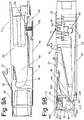
- the secondary lock will be described in further detail later. Suffice it to say that it basically comprises a pair of spring biased latches 68, each pivotably mounted within a respective retainer box 62 via a pivot pin 67 ( Figs. 4D and 5B ) extending through aligned holes in the opposed sidewalls of the retainer box 62.
- the latches are biased by respective springs (to be described later) so that each pivots to a closed or extended position at which it engages the a respective portion 38A at the free end of the projection 38 of the frame 26 to trap it when the two body members 22 and 24 are in the locked position like shown in Figs. 4D and 5B .
- Each of the latches 68 is arranged to be pivoted from the closed or extended position against the bias of its associated spring by the engagement of the free end of a respective lever forming a portion of the actuator subassembly.
- the actuator subassembly basically comprises the heretofore identified pivotable button 34, a pair of mounting brackets 74, a spring 76, a stop member 78, a pair of levers 80 and a pair of retainer plates 82 ( Figs. 3 and 4D ).
- the button 34 includes a flat top surface having a first end 34A on which indicia "PRESS HERE TO UNBLOCK" is provided and a second end 34B located opposite end 34A.
- the brackets 74 are mounted within respective recesses 32A ( Fig. 4A ) the frame 26 of the body member 22 via screws (not shown).
- the stop member 78 is mounted within a hollow portion of the frame 26 via respective mounting screws (not shown).
- a pivot rod 74A is journalled in the brackets 74 and extends through a transverse passageway in the button 34. It is about this rod that the button 34 is arranged to pivot.
- the spring 76 includes a helical central section 76A through which the pivot rod 74A extends and a pair of linear ends 76B and 76C.
- the linear end 76C engages and is trapped in the V-shaped center portion of the stop member 78, while the linear end 76B engages and is trapped in a curved recess in the portion 34A of the button 34 underlying the indicia.
- the button 34 is biased by the spring 76 so that it tends to assume the position shown in the locked state of Figs. 4C and 4D , whereupon its upper surface is flush with the upper surface of the frame 26 in which it is located.
- the stop member 78 not only serves to provide a fixed surface against which the linear end 76c of the spring engages, but also serves as a physical stop for the end portion of the button on which the indicia appears when that button is pushed to effect the release of the secondary lock.
- the underside of the button 34 includes a downwardly extending link 84 ( Fig. 4F ) from which a pair of rod-like members 86 project outwardly along a common axis.
- Each of the rod-like members is arranged to be coupled to an end of a respective lever 80.
- each lever 80 includes a yoke 80A at one end in which a respective rod-like member 86 of the link 84 is received.
- Each lever 80 is an elongated member having a free end located opposite the yoke 80A. The free end of each lever 80 will be described soon. Suffice it for now to state that it is arranged to be disposed within the upper portion of an associated recess 40 in the frame 26.
- the section line 4C of Fig. 1 is taken through the centerline of the recess 40.
- each lever 80 includes an upwardly projecting flat mesa 80B, a tapering undersurface 80C and a free end surface 80D.
- the mesa 80B is arranged to be received within a correspondingly shaped 88 notch ( Figs. 4D , 5B , 7B , 8B , and 9B ) at the entry to the upper portion of the recess 40 of the frame 26 of the body member 22.
- a respective retainer plate 82 is secured to the frame 26 by respective screws (not shown) so that it is located immediately below the lever 80 as shown in Figs. 4D and 5B and thus serves to hold the lever in place.
- the tabs 56 of the body member 24 are arranged to be received within the cavities 46 of the body member 22 when the two body members are docked together. Once they are docked the extension panel with the attached body member 24 can be oriented and moved so that its free end surface 58 is received within a correspondingly shaped recess 90 ( Figs. 4C and 5A ) located on the undersurface of an overhanging portion of the frame 26 to lock the two body members and their associated panels together.
- a correspondingly shaped recess 90 Figs. 4C and 5A
- the primary lock also includes two other components.
- bosses 42 and 44 of the frame member 26 and corresponding recesses or apertures 92 and 94 ( Fig. 4B ) in the frame 50 serve as the other primary lock components.
- the bosses 42 and 44 are arranged to be disposed within the apertures 92 and 94, respectively, when the two body members are locked together.
- These engaging bosses and apertures, coupled with the engaging tab surfaces 58 and recesses 90 prevent longitudinal and lateral displacement of the two body members with respect to each other.
- the secondary lock serves to prevent disengagement of the primary locking arrangement if an upward force is applied to the extension once it is in its locked state.
- each box includes a front wall 62A, a pair of opposed sidewalls (not shown) and a rear wall (not shown).
- Each latch is a pivotable hook-like member having a lower portion with a free end 68A and a recess or mouth 68B located immediately adjacent the free end 68A.
- the thickness of the latch is greater than the width of the upper portion of the recess 40 in which the free end of the lever is received, but is just slightly less than the width of the lower portion of the recess 40 so that it may fit within the lower portion of the recess 40 but not within the upper portion of the recess.
- the upper end of the latch 68 includes an aperture through which a pivot shaft 67 extends. Each pivot shaft extends through aligned openings in the opposed sidewalls of the associated retainer box, whereupon the associated latch is enabled to pivot about the pivot axis within the box.
- a pair of springs 96 is coupled to respective ones of the latches 68, with the pivot shaft 67 extending through the helical portion of the spring and with one linear portion 96A ( Fig. 5B ) of the spring engaging the bottom surface of a yoke 68C in the top portion of the latch 68 and the other linear portion 96B of the spring engaging the top surface of the associated retainer box.
- each latch 68 is biased to pivot outward (e.g., in the counterclockwise direction as shown in Figs. 4D and 5B ) about its pivot axis.
- the front wall 62A of each retainer box serves as a stop to prevent the associated spring from pivoting the associated latch beyond the orientation shown in Figs. 4D and 5B , wherein both latches are in the position to trap the free end portions 38A of the body member 22.
- Figs. 5A - 11B the operation of the joint assembly 20 to effect the disconnection (i.e., unlocking and undocking) of the extension panel 12 from the patient support panel 10 will now be described, it being assumed that the two panels had been previously docked and locked together.
- the state where they are locked together is shown in Figs 5A and 5B .
- the free end 58 of each of the tabs 56 of the frame 50 of the body member 24 are disposed within respective ones of the recesses 90 in the undersurface of the frame 26 of the body member 22.
- the bosses 42 and 44 of the frame 26 are received within their respective recesses or apertures 92 and 94 of the frame 50.
- the two projecting portions 38A of the frame 26 will be disposed within the mouths 68B of the two latches 68.
- the extension panel and the body member 24 to which it is secured will be prevented from pivoting upward more than a minimal amount, e.g., a few degrees.
- the primary lock i.e., the locking action provided by the engaging surfaces 58 with the recesses 90 and receipt of the bosses 42 and 44 within their respective apertures 92 and 94 will not be disconnected.
- the button 34 is depressed at the portion 34A to pivot it downward against the bias of the spring 76 to the position shown in Figs. 7A and 7B .
- This pivoting action of the button 34 causes its link 84 to pivot in the clockwise direction as shown in Fig. 7B .
- the pivoting of the link is coupled by the pins 86 to the yoke 80A of each of the levers 80, thereby carrying both levers to the left, whereupon each lever's mesa portion 80B is disposed within the associated recess 88 in the upper portion of each recess 40 of the frame 26.
- each lever 80 will start to bear on the tip portion 68A of the associated latch 68, thereby causing the latch to begin to pivot in the clockwise direction against the bias of its associated spring 96.
- This action also seats and holds the mesa portions 80B of the levers 80 in their respective recesses 88 (called the "stowed state").
- the upward pressure that the latch provides on the free end of the lever keeps the mesa end of the lever in its associated recess, thereby overcoming the bias that the spring 76 of the button applies to the button.
- the user can release pressure on the button, yet the button will stay in the released state shown in Figs. 7A and 7B (at this point operation of the release mechanism becomes hands-free).
- each lever 80 will cause the tip 68A of the associated latch 68 to ride along it, thereby pivoting both latches further in the clockwise direction. This action frees the projections 38A from the mouths 68B of the latches 68, thereby releasing the secondary lock.
- the engagement of the tip 68D of each lever on the surface 80C of the associated lever caused by the bias of the associated spring 96 still applies an upward force to the free end of the lever, thereby holding the associated lever 80 in its stowed state.
- each tab 56 will still be in engagement with its associated recess 90 in the frame 26, while the bosses 42 and 44 will be retracted somewhat from their respective recesses 92 and 94, so that the primary lock of the joint assembly will not be fully released at this point.
- the user continues to lift up on the extension panel in the direction of arrow U in Figs. 12A and 12B to bring the bodies 22 and 24 into what is called release stage 6.
- the surfaces 58 at the ends of the tabs 56 are out of their respective recesses 90 in the frame 50, and the bosses 42 and 44 are free of their respective apertures or recesses 92 and 94.
- the extension panel 12 with joint assembly body member 24 can then be removed from the patient support panel 10.
- connection of the extension panel to the patient support panel is accomplished in the following manner.
- the extension panel 12 with the body member 24 is lifted by a user and juxtaposed with respect to the body member 22 connected to patient support panel 10 like shown in Figs 13A and 13B (called insertion stage 1) so that the tabs 56 are guided by the guide plates 48 into their respective cavities 46 in the frame 26 of the body member 22.
- the pivotable button 34 is in its flush position because its spring 76 will have retracted the levers 80 to their retracted states shown in those figures.
- the latches 68 are biased to their maximum counterclockwise orientation by their associated springs 96, with the front wall 62A of the retainer boxes 62 serving as a stop to hold the latches in that state.
- the extension panel and the connected body member 24 can then be moved with respect to the body member 22 to the next insertion state or stage, which is the same as the heretofore identified release stage 5 ( Figs. 11A and 11B ).
- the extension panel and the connected body member can then be moved with respect to the body member 22 (e.g., inserted further and pivoted downward with respect to the plane of the patient support panel), which is the same as the heretofore identified release stage 4 ( Figs.
- the various components making up the joint assembly described heretofore are merely exemplary of various alternative components that can be used in accordance with this invention.
- the bosses and apertures for receiving the bosses may be reversed, e.g., the apertures or recesses 92 and 94 being located in the frame 26 of body 22 and the bosses 42 and 44 being located in the frame 50.
- the bosses themselves can be of a different construction. For example, as shown in Figs. 4G and 4H , the integral rectangular bosses 44 that control longitudinal and lateral play shown in Fig.
- bosses 44A may be replaced with a pair of alternative bosses 44A, each constructed like the single one shown in Fig. 4G .
- the bosses 44A are arranged to be received in correspondingly shaped recesses or apertures 94A shown in Fig. 4H and are made of acetal.
- Each boss is mounted on the frame 26 by an associated screw 44B.
- Each boss 44A has an end geometry that is spring like to allow for a small interference between it and the rectangular recess or aperture 94A where it resides to ensure stability of the extension panel especially at the distal end.
- the body members can be reversed, i.e., the body member 22 being secured to the extension panel and the body member 24 being secured to the patient support panel.
- the body members can be reversed, i.e., the body member 22 being secured to the extension panel and the body member 24 being secured to the patient support panel.
- redundant components i.e., two levers 80 and associated latches 68
- only one lever and one associated latch may be used. So too, only one tab and associated cavity for receiving it may be utilized, if appropriate.
- the construction of the latch and the lever for moving the latch can be modified as desired, preferably so long as the mechanism for disengaging the latch operates when initiated to unlock the latch and to hold the mechanism in a stowed state.
- the means for biasing for the latches and the pivotable button can be provided in other ways than shown.
- the actuator subassembly button, itself, may be replaced by a movable member that is not pivotable, so long as it is able to control the release of the secondary lock.
- the joint assembly and its associated patient support panel and extension panel provide a patient support structure that is easy to use and which eliminates potential failure either inadvertently or through operator error.
- the joint assembly provides a simple intuitive connection mechanism that is self aligning when docking.
- the joint solidly stabilizes and locks the two panels in relative alignment and level to (flush with) each other.
- a fail-safe secondary lock mechanism is included, that restricts inadvertent separation of the two panels if upward forces are encountered.
- the simple locking mechanism is largely located within the body member of the patient support panel which is fixed on the pedestal 14, thus reducing the potential harm that could occur to it if the extension panel was to be dropped or mishandled.
- the simple yet highly functional lock mechanism provided by the joint assembly provides several automatic operations starting with automatic engagement during docking of the extension panel to the patient support panel. When activated for release, this lock maintains the released position without further attention by the operator allowing the operator the opportunity to position both hands as best desired to securely grasp the extension panel for removal and handling. Importantly the lock mechanism provides this disengagement function without requiring displacement or movement of the removable extension panel. By not displacing or moving the extension panel when releasing the lock (or requiring external support such as may be provided by an operator) the subject invention avoids any need for a support beam or beams or a highly leveraged release mechanism that would otherwise be needed to offset the forces inherent in the preferred cantilevered configuration (no support beams) while not sacrificing the advantageous automatically locking feature when docking.
- the locking mechanism is additionally designed to automatically reset itself when the extension panel is removed so that it is always ready to automatically lock the next docked extension. If the operator should decide not to remove the extension panel after activating the lock release he/she may easily reactivate it by manually pressing the release lever back into the lock position (flush with the patient support panel top). For further insurance that the lock is always ready to automatically secure the next extension panel when docked it is designed such that it will not stay in the unlocked or released position except when an extension is in place (short of the operator secondarily holding the lever in the release position). This eliminates any potential failure that may arise due to an operator inadvertently disengaging the lock without an extension in place and forgetting to return it to the lock position.
- lock mechanism button is centrally located in the assembled components such that when in the released position it extends above the top surface in the path of the patient making it obvious visually and physically that the locking mechanism is disengaged. Being located under the patient also renders inadvertent release with a patient on board highly unlikely.
Landscapes
- Health & Medical Sciences (AREA)
- Life Sciences & Earth Sciences (AREA)
- Engineering & Computer Science (AREA)
- Biomedical Technology (AREA)
- Medical Informatics (AREA)
- Veterinary Medicine (AREA)
- Radiology & Medical Imaging (AREA)
- Animal Behavior & Ethology (AREA)
- General Health & Medical Sciences (AREA)
- Public Health (AREA)
- Nuclear Medicine, Radiotherapy & Molecular Imaging (AREA)
- Pathology (AREA)
- Biophysics (AREA)
- High Energy & Nuclear Physics (AREA)
- Physics & Mathematics (AREA)
- Optics & Photonics (AREA)
- Heart & Thoracic Surgery (AREA)
- Molecular Biology (AREA)
- Surgery (AREA)
- Accommodation For Nursing Or Treatment Tables (AREA)
- Radiation-Therapy Devices (AREA)
Claims (20)
- Verbindungsanordnung (20) zum lösbaren Verbinden einer Verlängerungsplatte (12) an eine Patientenlagerplatte (10), die an einem Sockel (14) angebracht ist, wobei die Verbindungsanordnung ein erstes Körperelement (22) und ein zweites Körperelement (24) umfasst, wobei eines von den ersten und zweiten Körperelementen (22, 24) angeordnet ist, um an der Patientenlagerplatte (10) befestigt zu werden, und wobei das andere der ersten und zweiten Körperelemente (22, 24) angeordnet ist, um an der Verlängerungsplatte (12) befestigt zu werden, wobei das erste Körperelement (22) eine Betätigungsunteranordnung (70) und einen Rahmen (26) umfasst, der einen Vorsprung (38, 38A), ein erstes Verriegelungselement (42, 44) und einen Überhang (26) einschließt, der eine Unterseite mit einer Aussparung (90) darin aufweist, wobei das zweite Körperelement (24) ein bewegliches Riegelelement (68) und einen Rahmen (50) umfasst, der einen distalen Abschnitt mit zumindest einem Laschenelement (56) und einem zweiten Verriegelungselement (92, 94) in Richtung eines proximalen Endes des Rahmens (50) einschließt, wobei das zweite Körperelement (24) mit der daran befestigten Verlängerungsplatte (12) angeordnet ist, um mit dem ersten Körperelement (22) in Eingriff gebracht zu werden, wobei ein Abschnitt des zumindest einen Laschenelements (56) lösbar in der Aussparung (90) des ersten Körperelements (22) aufgenommen wird und wobei die ersten und zweiten Verriegelungselemente (42, 44, 92, 94) ineinander eingreifen, um die ersten und zweiten Körperelemente (22, 24) gegeneinander zu verriegeln, um eine Abwärtsbewegung der Verlängerungsplatte (12) in Bezug auf die Patientenlagerplatte (10) zu verhindern, und wobei das bewegliche Riegelelement (68) des zweiten Körperelements (24) in den Vorsprung (38, 38A) des ersten Körperelements (22) eingreift, um die ersten und zweiten Körperelemente (22, 24) gegeneinander zu verriegeln und dadurch eine Aufwärtsbewegung der Verlängerungsplatte (12) in Bezug auf die Patientenlagerplatte (10) zu verhindern.
- Verbindungsanordnung nach Anspruch 1, wobei die Verbindungsanordnung konfiguriert ist, um sich selbst auszurichten, sich selbst zu nivellieren, sofort stabil zu sein und sich durch das Gewicht und den Abwärtsdruck auf das zweite Körperelement automatisch zu verriegeln, wenn die ersten und zweiten Körperelemente miteinander verbunden sind.
- Verbindungsanordnung nach Anspruch 1, wobei die Betätigungsunteranordnung eine manuell bewegliche Taste umfasst, deren Betriebsposition visuell anzeigt, ob die Verbindung verriegelt oder unverriegelt ist.
- Verbindungsanordnung nach Anspruch 1, wobei die Betätigungsunteranordnung zum Bewegen des Riegelelements angeordnet ist, um das Riegelelement aus dem Eingriff in dem Vorsprung zu lösen, wobei das zweite Körperelement mit der daran befestigten Verlängerungsplatte in Bezug auf das erste Körperelement nach oben geneigt werden kann, um den Abschnitt von dem zumindest einen Laschenelement von der Aussparung zu befreien und die ersten und zweiten Verriegelungselemente dazu zu veranlassen, voneinander außer Eingriff zu kommen und dadurch die ersten und zweiten Körperelemente voneinander zu entriegeln.
- Verbindungsanordnung nach Anspruch 4, wobei das erste Verriegelungselement eine Erhebung umfasst und wobei das zweite Verriegelungselement eine Aussparung zur lösbaren Aufnahme der Erhebung umfasst.
- Verbindungsanordnung nach Anspruch 1, wobei der bewegliche Riegelelement angeordnet ist, um in eine erste Drehrichtung um eine Achse geschwenkt zu werden, um den Vorsprung des ersten Körperelements lösbar in Eingriff zu nehmen.
- Verbindungsanordnung nach Anspruch 6, wobei der Riegelelement durch eine Feder in die erste Drehrichtung normal vorgespannt ist.
- Verbindungsanordnung nach Anspruch 7, wobei die Betätigungsunteranordnung einen Hebel umfasst, der ein freies Ende aufweist, das angeordnet ist, um zu einer ausgezogenen Position in Eingriff mit dem Riegelelement bewegt zu werden, um den Riegel in einer zweiten Drehrichtung gegenüber der ersten Drehrichtung um die Achse zu schwenken, um den Riegelelement aus dem Eingriff mit dem Vorsprung des ersten Körperelements zu lösen.
- Verbindungsanordnung nach Anspruch 8, wobei die Betätigungsanordnung eine schwenkbare Taste umfasst, die an den Hebel gekoppelt ist, und angeordnet ist, um die Taste in eine erste Drehrichtung zu schwenken, um den Hebel in die ausgezogene Position zu bewegen, wenn sie an einem ersten Punkt an der Taste eingedrückt wird.
- Verbindungsanordnung nach Anspruch 9, wobei es das Lösen des Vorsprungs von einem Haken dem zweiten Körperelement mit der daran befestigten Verlängerungsplatte ermöglicht, in Bezug auf das erste Körperelement nach oben geneigt zu werden, um den Abschnitt von dem zumindest einen Laschenelement von der Aussparung zu befreien und die ersten und zweiten Verriegelungselemente dazu zu veranlassen, voneinander außer Eingriff zu kommen, um dadurch die ersten und zweiten Körperelemente voneinander zu entriegeln, wodurch das zweite Körperelement mit der daran befestigten Verlängerungsplatte bewegt werden kann.
- Verbindungsanordnung nach Anspruch 10, wobei die Taste durch eine Feder normal vorgespannt ist, um die Taste in eine zweite Drehrichtung zu schwenken, wobei die zweite Drehrichtung gegenüber der ersten Drehrichtung liegt.
- Verbindungsanordnung nach Anspruch 11, wobei das freie Ende des Hebels eine Oberfläche einschließt, die angeordnet ist, um eine entsprechend geformte Oberfläche des Vorsprungs in Eingriff zu nehmen, wenn der Hebel in der ausgezogenen Position gehalten wird.
- Verbindungsanordnung nach Anspruch 12, wobei der in der ausgezogenen Position an dem Hebel anliegende Riegel die Oberfläche des Hebels gegen die durch die Feder bereitgestellte auf der Taste bereitgestellte Vorspannung in Eingriff mit der entsprechend geformten Oberfläche des Vorsprungs hält.
- Verbindungsanordnung nach Anspruch 12, wobei der Riegel angeordnet ist, um in eine nicht an dem Hebel anliegende Position bewegt zu werden, wodurch das Federvorspannen der Taste die Oberfläche des Hebels dazu veranlasst, von der entsprechend geformten Oberfläche des Vorsprungs außer Eingriff zu kommen, wodurch sich der Hebel in eine eingezogene Position bewegt.
- Patientenlagerplatte, die die Verbindungsanordnung, die Patientenlagerplatte und die Verlängerungsplatte nach Anspruch 1 umfasst.
- Patientenlagerplatte nach Anspruch 15, wobei die Patientenlagerplatte ein Strahlentherapiebehandlungstisch ist.
- Patientenlagerplatte nach Anspruch 16, wobei die Patientenlagerplatte zumindest eine Komponente einschließt, die es der Patientenlagerplatte ermöglicht, an dem Sockel befestigt zu werden.
- Patientenlagerplatte nach Anspruch 16, wobei die Patientenlagerplatte und die Verlängerungsplatte jeweils aus einem Kohlenstoffverbundmaterial gebildet ist.
- Patientenlagerplatte nach Anspruch 17, wobei die Patientenlagerplatte und die Verlängerungsplatte jeweils aus einem Kohlenstoffverbundmaterial gebildet ist.
- Patientenlagerplatte nach Anspruch 16, wobei die Betätigungsanordnung eine manuell bewegliche Taste umfasst, deren Betriebsposition visuell anzeigt, ob die Verbindung verriegelt oder unverriegelt ist.
Applications Claiming Priority (2)
| Application Number | Priority Date | Filing Date | Title |
|---|---|---|---|
| US13/477,433 US8966687B2 (en) | 2012-05-22 | 2012-05-22 | Joint assembly for connecting a long extension panel to a patient support panel of a radiation therapy table and a two-piece patient support table formed thereby |
| PCT/US2013/041978 WO2013177131A1 (en) | 2012-05-22 | 2013-05-21 | Joint assembly for connecting a long extension panel to a patient support panel of a radiation therapy table and a two-piece patient support table formed thereby |
Publications (2)
| Publication Number | Publication Date |
|---|---|
| EP2852325A1 EP2852325A1 (de) | 2015-04-01 |
| EP2852325B1 true EP2852325B1 (de) | 2017-01-11 |
Family
ID=48539428
Family Applications (1)
| Application Number | Title | Priority Date | Filing Date |
|---|---|---|---|
| EP13726378.6A Active EP2852325B1 (de) | 2012-05-22 | 2013-05-21 | Gelenkanordnung zum verbinden einer langen erweiterungsplatte mit einer patientenliege eines strahlentherapietisches und daraus hergestellter zweiteiliger patiententisch |
Country Status (9)
| Country | Link |
|---|---|
| US (1) | US8966687B2 (de) |
| EP (1) | EP2852325B1 (de) |
| JP (1) | JP6138926B2 (de) |
| KR (2) | KR101948743B1 (de) |
| CN (2) | CN107789748B (de) |
| AU (2) | AU2013266494B2 (de) |
| CA (2) | CA2874433C (de) |
| IN (1) | IN2014DN10362A (de) |
| WO (1) | WO2013177131A1 (de) |
Families Citing this family (6)
| Publication number | Priority date | Publication date | Assignee | Title |
|---|---|---|---|---|
| GB2534738B (en) * | 2013-07-12 | 2017-01-11 | Eschmann Holdings Ltd | Tabletop sections for surgical tables |
| JP7178714B2 (ja) | 2016-11-15 | 2022-11-28 | リフレクション メディカル, インコーポレイテッド | 放射線療法患者プラットフォーム |
| JP7126860B2 (ja) * | 2018-05-18 | 2022-08-29 | キヤノンメディカルシステムズ株式会社 | 放射線治療装置 |
| BE1026472B1 (nl) * | 2018-07-16 | 2020-02-10 | Orfit Ind | Eerste rompelement van een verbindingssamenstel voor het losneembaar verbinden van een uitbreidingspaneel met een patiëntondersteuningspaneel dat gemonteerd is op een voetstuk |
| US11717238B2 (en) * | 2019-12-15 | 2023-08-08 | Siemens Healthineers International Ag | Couch top extension for radiation therapy and imaging |
| US11267058B2 (en) * | 2020-01-29 | 2022-03-08 | Robert Bosch Gmbh | Table saw including tip-in table extension |
Family Cites Families (36)
| Publication number | Priority date | Publication date | Assignee | Title |
|---|---|---|---|---|
| US3695189A (en) * | 1970-07-13 | 1972-10-03 | Johann Felder Jr | Removable extension plate |
| GB2100121B (en) * | 1981-05-11 | 1985-03-27 | Midland Repetition The Co Ltd | Means for aligning and linking together articles such as furniture |
| DE3635288A1 (de) * | 1986-10-16 | 1988-04-21 | Wilkhahn Wilkening & Hahne | Tischsystem |
| DE9214382U1 (de) | 1992-04-01 | 1992-12-17 | Siemens AG, 80333 München | Patientenlagerungsplatte |
| US5588771A (en) * | 1995-04-20 | 1996-12-31 | Kejr Engineering, Inc. | Connector for coupling a pair of rods |
| US5661859A (en) | 1995-10-20 | 1997-09-02 | Midmark Corporation | Shoulder arthoscopy attachment |
| US5678948A (en) * | 1995-12-07 | 1997-10-21 | B. Walter And Co., Inc. | Selectively lockable and horizontally and vertically aligning latch for furniture parts |
| US5675851A (en) | 1996-10-08 | 1997-10-14 | Feathers; John A. | X-ray table extension for head and upper body support |
| US6199233B1 (en) | 1998-04-24 | 2001-03-13 | Allen Kantrowitz | Radiolucent table extension assembly |
| JP2002536119A (ja) | 1999-02-11 | 2002-10-29 | オハイオ メディカル インスツルメント カンパニー,インコーポレイテッド | 放射線透過性テーブル延長部用のヒンジ式アダプタ装置 |
| US6813788B2 (en) | 2000-04-06 | 2004-11-09 | Schaerer Mayfield Usa, Inc. | Variable length radiolucent surgical table extension |
| WO2002058616A2 (en) | 2001-01-25 | 2002-08-01 | Hill-Rom Services, Inc. | Head section support for a surgical table |
| US6598275B1 (en) * | 2001-03-12 | 2003-07-29 | Steris, Inc. | Low shadow radiolucent surgical table, clamp systems, and accessories therefore |
| US7020917B1 (en) * | 2001-03-12 | 2006-04-04 | Steris Corporation | Radiolucent surgical table with low shadow accessory interface profile |
| JP2003135446A (ja) * | 2001-10-30 | 2003-05-13 | Toshiba Corp | 画像診断用寝台装置の付属品 |
| US6640364B1 (en) * | 2001-11-30 | 2003-11-04 | Ge Medical Systems Global Technololgy Company, Llc | Pedestal for use with patient transport system for multiple imaging systems |
| CN2558329Y (zh) * | 2002-01-16 | 2003-07-02 | 吴俊江 | 三维立体可移动式治疗床 |
| US6721976B2 (en) * | 2002-02-05 | 2004-04-20 | Reliance Medical Products, Inc. | Surgical table |
| DE10228839C1 (de) | 2002-06-27 | 2003-10-30 | Dornier Medtech Gmbh | Patientenliege |
| US6941599B2 (en) | 2002-08-20 | 2005-09-13 | Aktina Medical Corp. | Radiotherapy treatment and imaging patient support table |
| US6832400B2 (en) * | 2002-12-19 | 2004-12-21 | Cti Pet Systems, Inc. | Patient handling system and associated pallet mounting apparatus |
| US7272866B1 (en) * | 2003-05-01 | 2007-09-25 | Bradcovich James M | Attachment mechanism for medical patient platform |
| NL1024063C2 (nl) | 2003-08-07 | 2005-02-08 | Sinmed B V | Modulair patientondersteuningssysteem voor toepassing bij radiotherapeutische behandelingen. |
| GB2405789B (en) | 2003-09-11 | 2005-08-17 | Elekta Ab | Patient table |
| US7210180B2 (en) | 2003-10-20 | 2007-05-01 | Malcolm Roger J | Surgical table width extension and angularly orientable attachment |
| DE102004047509B4 (de) | 2004-09-28 | 2007-02-01 | Siemens Ag | Befestigungsvorrichtung zum Befestigen eines Zubehörteils an einer Patientenliege |
| DE102005030378A1 (de) | 2005-06-29 | 2007-01-04 | Siemens Ag | Patiententisch für eine Röntgenanlage |
| WO2007106877A2 (en) | 2006-03-14 | 2007-09-20 | Qfix Systems, Llc | Radiolucent patient treatment table with removable tip extension base and accessories |
| EP2185031A4 (de) | 2007-08-24 | 2014-12-24 | Allen Medical Systems Inc | Zusatzplattform für operationstisch |
| CN201119966Y (zh) * | 2007-11-22 | 2008-09-24 | 李乾坤 | 透视型手术台 |
| JP5084562B2 (ja) * | 2008-03-03 | 2012-11-28 | パラマウントベッド株式会社 | ベッドにおける足ボトムの支持機構 |
| US8146599B2 (en) | 2008-06-17 | 2012-04-03 | Civco Medical Instruments Co., Inc. | Patient positioning system |
| DE202008016701U1 (de) | 2008-12-18 | 2010-04-29 | Reuther Medizintechnik Gmbh & Co. Kg | Modulares Tischsystem, insbesondere für die Strahlentherapie |
| CN102127956A (zh) * | 2010-01-12 | 2011-07-20 | 李增清 | 铺板连接件及铺板连接结构 |
| CN201744086U (zh) * | 2010-07-15 | 2011-02-16 | 山东新华医疗器械股份有限公司 | 放射治疗设备用组合式床面 |
| CN201939896U (zh) * | 2010-12-10 | 2011-08-24 | 江苏海明医疗器械有限公司 | 一种用于放射治疗的治疗床床面 |
-
2012
- 2012-05-22 US US13/477,433 patent/US8966687B2/en active Active
-
2013
- 2013-05-21 IN IN10362DEN2014 patent/IN2014DN10362A/en unknown
- 2013-05-21 CN CN201711079172.2A patent/CN107789748B/zh active Active
- 2013-05-21 AU AU2013266494A patent/AU2013266494B2/en active Active
- 2013-05-21 CA CA2874433A patent/CA2874433C/en active Active
- 2013-05-21 CN CN201380038792.5A patent/CN104640504B/zh active Active
- 2013-05-21 EP EP13726378.6A patent/EP2852325B1/de active Active
- 2013-05-21 KR KR1020177035335A patent/KR101948743B1/ko active Active
- 2013-05-21 JP JP2015514103A patent/JP6138926B2/ja active Active
- 2013-05-21 WO PCT/US2013/041978 patent/WO2013177131A1/en not_active Ceased
- 2013-05-21 KR KR1020147035978A patent/KR101948755B1/ko active Active
- 2013-05-21 CA CA3054205A patent/CA3054205C/en active Active
-
2017
- 2017-10-11 AU AU2017245336A patent/AU2017245336B2/en active Active
Non-Patent Citations (1)
| Title |
|---|
| None * |
Also Published As
| Publication number | Publication date |
|---|---|
| AU2017245336A1 (en) | 2017-11-02 |
| KR101948743B1 (ko) | 2019-05-30 |
| CA2874433A1 (en) | 2013-11-28 |
| IN2014DN10362A (de) | 2015-08-07 |
| WO2013177131A1 (en) | 2013-11-28 |
| KR20170141259A (ko) | 2017-12-22 |
| CN107789748A (zh) | 2018-03-13 |
| CN104640504B (zh) | 2017-12-08 |
| CA2874433C (en) | 2019-10-15 |
| JP6138926B2 (ja) | 2017-05-31 |
| US20130312184A1 (en) | 2013-11-28 |
| CA3054205C (en) | 2022-04-12 |
| KR20150040810A (ko) | 2015-04-15 |
| US8966687B2 (en) | 2015-03-03 |
| EP2852325A1 (de) | 2015-04-01 |
| KR101948755B1 (ko) | 2019-04-22 |
| CN107789748B (zh) | 2020-04-07 |
| AU2017245336B2 (en) | 2019-02-21 |
| CA3054205A1 (en) | 2013-11-28 |
| AU2013266494A1 (en) | 2014-12-18 |
| AU2013266494B2 (en) | 2017-07-13 |
| CN104640504A (zh) | 2015-05-20 |
| JP2015517386A (ja) | 2015-06-22 |
Similar Documents
| Publication | Publication Date | Title |
|---|---|---|
| AU2017245336B2 (en) | Joint assembly for connecting a long extension panel to a patient support panel of a radiation therapy table and a two-piece patient support table formed thereby | |
| CN104619301B (zh) | 手术台顶部组件及相关装置 | |
| US9187108B2 (en) | Folding cart for portable grill | |
| EP3000455B1 (de) | Barriere für ein bett | |
| JP5927029B2 (ja) | テーブル装置 | |
| US20140008954A1 (en) | Detachable seating device | |
| JP2002369728A (ja) | ヘッドレストサポート | |
| JP6180044B2 (ja) | 転倒防止機器 | |
| US20190142662A1 (en) | Collapsible mobility aid | |
| JP6621333B2 (ja) | 医療台 | |
| JP2016097236A (ja) | 昇降する天板をもつ昇降台のロック機構 | |
| CN117582354B (zh) | 一种医疗床 | |
| JP7522013B2 (ja) | 柱材と横材の係止装置 | |
| CZ319092A3 (en) | Support for stretcher | |
| JP2004182147A (ja) | 横跳ね収納式スライドシート |
Legal Events
| Date | Code | Title | Description |
|---|---|---|---|
| PUAI | Public reference made under article 153(3) epc to a published international application that has entered the european phase |
Free format text: ORIGINAL CODE: 0009012 |
|
| 17P | Request for examination filed |
Effective date: 20141219 |
|
| AK | Designated contracting states |
Kind code of ref document: A1 Designated state(s): AL AT BE BG CH CY CZ DE DK EE ES FI FR GB GR HR HU IE IS IT LI LT LU LV MC MK MT NL NO PL PT RO RS SE SI SK SM TR |
|
| AX | Request for extension of the european patent |
Extension state: BA ME |
|
| RAP1 | Party data changed (applicant data changed or rights of an application transferred) |
Owner name: MEDTEC, INC. |
|
| DAX | Request for extension of the european patent (deleted) | ||
| REG | Reference to a national code |
Ref country code: DE Ref legal event code: R079 Ref document number: 602013016459 Country of ref document: DE Free format text: PREVIOUS MAIN CLASS: A61B0006040000 Ipc: A61N0005100000 |
|
| GRAP | Despatch of communication of intention to grant a patent |
Free format text: ORIGINAL CODE: EPIDOSNIGR1 |
|
| RIC1 | Information provided on ipc code assigned before grant |
Ipc: A61N 5/10 20060101AFI20160614BHEP Ipc: A61B 6/04 20060101ALI20160614BHEP |
|
| INTG | Intention to grant announced |
Effective date: 20160704 |
|
| GRAJ | Information related to disapproval of communication of intention to grant by the applicant or resumption of examination proceedings by the epo deleted |
Free format text: ORIGINAL CODE: EPIDOSDIGR1 |
|
| GRAR | Information related to intention to grant a patent recorded |
Free format text: ORIGINAL CODE: EPIDOSNIGR71 |
|
| GRAS | Grant fee paid |
Free format text: ORIGINAL CODE: EPIDOSNIGR3 |
|
| INTC | Intention to grant announced (deleted) | ||
| GRAA | (expected) grant |
Free format text: ORIGINAL CODE: 0009210 |
|
| INTG | Intention to grant announced |
Effective date: 20161201 |
|
| AK | Designated contracting states |
Kind code of ref document: B1 Designated state(s): AL AT BE BG CH CY CZ DE DK EE ES FI FR GB GR HR HU IE IS IT LI LT LU LV MC MK MT NL NO PL PT RO RS SE SI SK SM TR |
|
| REG | Reference to a national code |
Ref country code: GB Ref legal event code: FG4D |
|
| REG | Reference to a national code |
Ref country code: CH Ref legal event code: EP |
|
| REG | Reference to a national code |
Ref country code: AT Ref legal event code: REF Ref document number: 860714 Country of ref document: AT Kind code of ref document: T Effective date: 20170115 |
|
| REG | Reference to a national code |
Ref country code: IE Ref legal event code: FG4D |
|
| REG | Reference to a national code |
Ref country code: DE Ref legal event code: R096 Ref document number: 602013016459 Country of ref document: DE |
|
| REG | Reference to a national code |
Ref country code: NL Ref legal event code: FP |
|
| REG | Reference to a national code |
Ref country code: LT Ref legal event code: MG4D |
|
| REG | Reference to a national code |
Ref country code: AT Ref legal event code: MK05 Ref document number: 860714 Country of ref document: AT Kind code of ref document: T Effective date: 20170111 |
|
| PG25 | Lapsed in a contracting state [announced via postgrant information from national office to epo] |
Ref country code: GR Free format text: LAPSE BECAUSE OF FAILURE TO SUBMIT A TRANSLATION OF THE DESCRIPTION OR TO PAY THE FEE WITHIN THE PRESCRIBED TIME-LIMIT Effective date: 20170412 Ref country code: FI Free format text: LAPSE BECAUSE OF FAILURE TO SUBMIT A TRANSLATION OF THE DESCRIPTION OR TO PAY THE FEE WITHIN THE PRESCRIBED TIME-LIMIT Effective date: 20170111 Ref country code: IS Free format text: LAPSE BECAUSE OF FAILURE TO SUBMIT A TRANSLATION OF THE DESCRIPTION OR TO PAY THE FEE WITHIN THE PRESCRIBED TIME-LIMIT Effective date: 20170511 Ref country code: LT Free format text: LAPSE BECAUSE OF FAILURE TO SUBMIT A TRANSLATION OF THE DESCRIPTION OR TO PAY THE FEE WITHIN THE PRESCRIBED TIME-LIMIT Effective date: 20170111 Ref country code: HR Free format text: LAPSE BECAUSE OF FAILURE TO SUBMIT A TRANSLATION OF THE DESCRIPTION OR TO PAY THE FEE WITHIN THE PRESCRIBED TIME-LIMIT Effective date: 20170111 Ref country code: NO Free format text: LAPSE BECAUSE OF FAILURE TO SUBMIT A TRANSLATION OF THE DESCRIPTION OR TO PAY THE FEE WITHIN THE PRESCRIBED TIME-LIMIT Effective date: 20170411 |
|
| PG25 | Lapsed in a contracting state [announced via postgrant information from national office to epo] |
Ref country code: LV Free format text: LAPSE BECAUSE OF FAILURE TO SUBMIT A TRANSLATION OF THE DESCRIPTION OR TO PAY THE FEE WITHIN THE PRESCRIBED TIME-LIMIT Effective date: 20170111 Ref country code: PT Free format text: LAPSE BECAUSE OF FAILURE TO SUBMIT A TRANSLATION OF THE DESCRIPTION OR TO PAY THE FEE WITHIN THE PRESCRIBED TIME-LIMIT Effective date: 20170511 Ref country code: LU Free format text: LAPSE BECAUSE OF NON-PAYMENT OF DUE FEES Effective date: 20170531 Ref country code: RS Free format text: LAPSE BECAUSE OF FAILURE TO SUBMIT A TRANSLATION OF THE DESCRIPTION OR TO PAY THE FEE WITHIN THE PRESCRIBED TIME-LIMIT Effective date: 20170111 Ref country code: PL Free format text: LAPSE BECAUSE OF FAILURE TO SUBMIT A TRANSLATION OF THE DESCRIPTION OR TO PAY THE FEE WITHIN THE PRESCRIBED TIME-LIMIT Effective date: 20170111 Ref country code: ES Free format text: LAPSE BECAUSE OF FAILURE TO SUBMIT A TRANSLATION OF THE DESCRIPTION OR TO PAY THE FEE WITHIN THE PRESCRIBED TIME-LIMIT Effective date: 20170111 Ref country code: SE Free format text: LAPSE BECAUSE OF FAILURE TO SUBMIT A TRANSLATION OF THE DESCRIPTION OR TO PAY THE FEE WITHIN THE PRESCRIBED TIME-LIMIT Effective date: 20170111 Ref country code: BG Free format text: LAPSE BECAUSE OF FAILURE TO SUBMIT A TRANSLATION OF THE DESCRIPTION OR TO PAY THE FEE WITHIN THE PRESCRIBED TIME-LIMIT Effective date: 20170411 Ref country code: AT Free format text: LAPSE BECAUSE OF FAILURE TO SUBMIT A TRANSLATION OF THE DESCRIPTION OR TO PAY THE FEE WITHIN THE PRESCRIBED TIME-LIMIT Effective date: 20170111 |
|
| REG | Reference to a national code |
Ref country code: DE Ref legal event code: R097 Ref document number: 602013016459 Country of ref document: DE |
|
| PG25 | Lapsed in a contracting state [announced via postgrant information from national office to epo] |
Ref country code: RO Free format text: LAPSE BECAUSE OF FAILURE TO SUBMIT A TRANSLATION OF THE DESCRIPTION OR TO PAY THE FEE WITHIN THE PRESCRIBED TIME-LIMIT Effective date: 20170111 Ref country code: IT Free format text: LAPSE BECAUSE OF FAILURE TO SUBMIT A TRANSLATION OF THE DESCRIPTION OR TO PAY THE FEE WITHIN THE PRESCRIBED TIME-LIMIT Effective date: 20170111 Ref country code: SK Free format text: LAPSE BECAUSE OF FAILURE TO SUBMIT A TRANSLATION OF THE DESCRIPTION OR TO PAY THE FEE WITHIN THE PRESCRIBED TIME-LIMIT Effective date: 20170111 Ref country code: EE Free format text: LAPSE BECAUSE OF FAILURE TO SUBMIT A TRANSLATION OF THE DESCRIPTION OR TO PAY THE FEE WITHIN THE PRESCRIBED TIME-LIMIT Effective date: 20170111 Ref country code: CZ Free format text: LAPSE BECAUSE OF FAILURE TO SUBMIT A TRANSLATION OF THE DESCRIPTION OR TO PAY THE FEE WITHIN THE PRESCRIBED TIME-LIMIT Effective date: 20170111 |
|
| PLBE | No opposition filed within time limit |
Free format text: ORIGINAL CODE: 0009261 |
|
| STAA | Information on the status of an ep patent application or granted ep patent |
Free format text: STATUS: NO OPPOSITION FILED WITHIN TIME LIMIT |
|
| PG25 | Lapsed in a contracting state [announced via postgrant information from national office to epo] |
Ref country code: DK Free format text: LAPSE BECAUSE OF FAILURE TO SUBMIT A TRANSLATION OF THE DESCRIPTION OR TO PAY THE FEE WITHIN THE PRESCRIBED TIME-LIMIT Effective date: 20170111 Ref country code: SM Free format text: LAPSE BECAUSE OF FAILURE TO SUBMIT A TRANSLATION OF THE DESCRIPTION OR TO PAY THE FEE WITHIN THE PRESCRIBED TIME-LIMIT Effective date: 20170111 |
|
| 26N | No opposition filed |
Effective date: 20171012 |
|
| REG | Reference to a national code |
Ref country code: CH Ref legal event code: PL |
|
| PG25 | Lapsed in a contracting state [announced via postgrant information from national office to epo] |
Ref country code: MC Free format text: LAPSE BECAUSE OF FAILURE TO SUBMIT A TRANSLATION OF THE DESCRIPTION OR TO PAY THE FEE WITHIN THE PRESCRIBED TIME-LIMIT Effective date: 20170111 |
|
| REG | Reference to a national code |
Ref country code: IE Ref legal event code: MM4A |
|
| PG25 | Lapsed in a contracting state [announced via postgrant information from national office to epo] |
Ref country code: SI Free format text: LAPSE BECAUSE OF FAILURE TO SUBMIT A TRANSLATION OF THE DESCRIPTION OR TO PAY THE FEE WITHIN THE PRESCRIBED TIME-LIMIT Effective date: 20170111 Ref country code: CH Free format text: LAPSE BECAUSE OF NON-PAYMENT OF DUE FEES Effective date: 20170531 Ref country code: LI Free format text: LAPSE BECAUSE OF NON-PAYMENT OF DUE FEES Effective date: 20170531 |
|
| REG | Reference to a national code |
Ref country code: FR Ref legal event code: ST Effective date: 20180131 |
|
| PG25 | Lapsed in a contracting state [announced via postgrant information from national office to epo] |
Ref country code: LU Free format text: LAPSE BECAUSE OF NON-PAYMENT OF DUE FEES Effective date: 20170521 |
|
| PG25 | Lapsed in a contracting state [announced via postgrant information from national office to epo] |
Ref country code: IE Free format text: LAPSE BECAUSE OF NON-PAYMENT OF DUE FEES Effective date: 20170521 |
|
| PG25 | Lapsed in a contracting state [announced via postgrant information from national office to epo] |
Ref country code: FR Free format text: LAPSE BECAUSE OF NON-PAYMENT OF DUE FEES Effective date: 20170531 |
|
| PG25 | Lapsed in a contracting state [announced via postgrant information from national office to epo] |
Ref country code: MT Free format text: LAPSE BECAUSE OF NON-PAYMENT OF DUE FEES Effective date: 20170521 |
|
| PG25 | Lapsed in a contracting state [announced via postgrant information from national office to epo] |
Ref country code: HU Free format text: LAPSE BECAUSE OF FAILURE TO SUBMIT A TRANSLATION OF THE DESCRIPTION OR TO PAY THE FEE WITHIN THE PRESCRIBED TIME-LIMIT; INVALID AB INITIO Effective date: 20130521 |
|
| PG25 | Lapsed in a contracting state [announced via postgrant information from national office to epo] |
Ref country code: CY Free format text: LAPSE BECAUSE OF FAILURE TO SUBMIT A TRANSLATION OF THE DESCRIPTION OR TO PAY THE FEE WITHIN THE PRESCRIBED TIME-LIMIT Effective date: 20170111 |
|
| PG25 | Lapsed in a contracting state [announced via postgrant information from national office to epo] |
Ref country code: MK Free format text: LAPSE BECAUSE OF FAILURE TO SUBMIT A TRANSLATION OF THE DESCRIPTION OR TO PAY THE FEE WITHIN THE PRESCRIBED TIME-LIMIT Effective date: 20170111 |
|
| PG25 | Lapsed in a contracting state [announced via postgrant information from national office to epo] |
Ref country code: TR Free format text: LAPSE BECAUSE OF FAILURE TO SUBMIT A TRANSLATION OF THE DESCRIPTION OR TO PAY THE FEE WITHIN THE PRESCRIBED TIME-LIMIT Effective date: 20170111 |
|
| PG25 | Lapsed in a contracting state [announced via postgrant information from national office to epo] |
Ref country code: AL Free format text: LAPSE BECAUSE OF FAILURE TO SUBMIT A TRANSLATION OF THE DESCRIPTION OR TO PAY THE FEE WITHIN THE PRESCRIBED TIME-LIMIT Effective date: 20170111 |
|
| REG | Reference to a national code |
Ref country code: NL Ref legal event code: PD Owner name: MEDTEC LLC; US Free format text: DETAILS ASSIGNMENT: CHANGE OF OWNER(S), CHANGE OF LEGAL ENTITY; FORMER OWNER NAME: MEDTEC, INC. Effective date: 20211102 |
|
| REG | Reference to a national code |
Ref country code: DE Ref legal event code: R081 Ref document number: 602013016459 Country of ref document: DE Owner name: MEDTEC LLC, ORANGE CITY, US Free format text: FORMER OWNER: MEDTEC, INC., ORANGE CITY, IA., US Ref country code: DE Ref legal event code: R082 Ref document number: 602013016459 Country of ref document: DE Representative=s name: HGF EUROPE LLP, DE |
|
| REG | Reference to a national code |
Ref country code: BE Ref legal event code: PD Owner name: MEDTEC LLC; US Free format text: DETAILS ASSIGNMENT: CHANGE OF OWNER(S), CHANGE OF LEGAL ENTITY; FORMER OWNER NAME: MEDTEC, INC. Effective date: 20211221 |
|
| P01 | Opt-out of the competence of the unified patent court (upc) registered |
Effective date: 20230530 |
|
| PGFP | Annual fee paid to national office [announced via postgrant information from national office to epo] |
Ref country code: NL Payment date: 20250522 Year of fee payment: 13 |
|
| PGFP | Annual fee paid to national office [announced via postgrant information from national office to epo] |
Ref country code: DE Payment date: 20250519 Year of fee payment: 13 |
|
| PGFP | Annual fee paid to national office [announced via postgrant information from national office to epo] |
Ref country code: GB Payment date: 20250527 Year of fee payment: 13 |
|
| PGFP | Annual fee paid to national office [announced via postgrant information from national office to epo] |
Ref country code: BE Payment date: 20250523 Year of fee payment: 13 |