EP2851631B1 - Wärmepumpenvorrichtung, klimaanlage und kältemaschine - Google Patents
Wärmepumpenvorrichtung, klimaanlage und kältemaschine Download PDFInfo
- Publication number
- EP2851631B1 EP2851631B1 EP12874570.0A EP12874570A EP2851631B1 EP 2851631 B1 EP2851631 B1 EP 2851631B1 EP 12874570 A EP12874570 A EP 12874570A EP 2851631 B1 EP2851631 B1 EP 2851631B1
- Authority
- EP
- European Patent Office
- Prior art keywords
- voltage
- inverter
- motor
- heat pump
- pump device
- Prior art date
- Legal status (The legal status is an assumption and is not a legal conclusion. Google has not performed a legal analysis and makes no representation as to the accuracy of the status listed.)
- Active
Links
- 238000001816 cooling Methods 0.000 title description 10
- 239000003507 refrigerant Substances 0.000 claims description 81
- 238000010438 heat treatment Methods 0.000 claims description 49
- 230000007246 mechanism Effects 0.000 claims description 29
- 238000001514 detection method Methods 0.000 claims description 13
- 239000004065 semiconductor Substances 0.000 claims description 13
- HBMJWWWQQXIZIP-UHFFFAOYSA-N silicon carbide Chemical group [Si+]#[C-] HBMJWWWQQXIZIP-UHFFFAOYSA-N 0.000 claims description 11
- 229910010271 silicon carbide Inorganic materials 0.000 claims description 11
- 230000006835 compression Effects 0.000 claims description 8
- 238000007906 compression Methods 0.000 claims description 8
- JMASRVWKEDWRBT-UHFFFAOYSA-N Gallium nitride Chemical compound [Ga]#N JMASRVWKEDWRBT-UHFFFAOYSA-N 0.000 claims description 2
- 239000010432 diamond Substances 0.000 claims description 2
- 229910003460 diamond Inorganic materials 0.000 claims description 2
- 229910002601 GaN Inorganic materials 0.000 claims 1
- 239000000463 material Substances 0.000 claims 1
- 239000012071 phase Substances 0.000 description 83
- 239000013598 vector Substances 0.000 description 24
- XLYOFNOQVPJJNP-UHFFFAOYSA-N water Substances O XLYOFNOQVPJJNP-UHFFFAOYSA-N 0.000 description 23
- 238000010586 diagram Methods 0.000 description 22
- 238000002347 injection Methods 0.000 description 21
- 239000007924 injection Substances 0.000 description 21
- 239000007788 liquid Substances 0.000 description 21
- 238000000034 method Methods 0.000 description 20
- 238000004804 winding Methods 0.000 description 18
- 230000020169 heat generation Effects 0.000 description 14
- 230000000694 effects Effects 0.000 description 9
- 239000007791 liquid phase Substances 0.000 description 9
- 230000002829 reductive effect Effects 0.000 description 8
- 230000008859 change Effects 0.000 description 6
- XEEYBQQBJWHFJM-UHFFFAOYSA-N Iron Chemical compound [Fe] XEEYBQQBJWHFJM-UHFFFAOYSA-N 0.000 description 5
- 230000007423 decrease Effects 0.000 description 5
- 230000009467 reduction Effects 0.000 description 4
- 230000015556 catabolic process Effects 0.000 description 3
- 230000001360 synchronised effect Effects 0.000 description 3
- 238000004378 air conditioning Methods 0.000 description 2
- 230000003247 decreasing effect Effects 0.000 description 2
- 230000007613 environmental effect Effects 0.000 description 2
- 230000005669 field effect Effects 0.000 description 2
- 229910052742 iron Inorganic materials 0.000 description 2
- 238000011084 recovery Methods 0.000 description 2
- 238000010992 reflux Methods 0.000 description 2
- 238000005057 refrigeration Methods 0.000 description 2
- 230000001629 suppression Effects 0.000 description 2
- 230000007704 transition Effects 0.000 description 2
- RYGMFSIKBFXOCR-UHFFFAOYSA-N Copper Chemical compound [Cu] RYGMFSIKBFXOCR-UHFFFAOYSA-N 0.000 description 1
- XUIMIQQOPSSXEZ-UHFFFAOYSA-N Silicon Chemical compound [Si] XUIMIQQOPSSXEZ-UHFFFAOYSA-N 0.000 description 1
- 230000002411 adverse Effects 0.000 description 1
- 238000013459 approach Methods 0.000 description 1
- 230000008901 benefit Effects 0.000 description 1
- 239000003990 capacitor Substances 0.000 description 1
- 229910052802 copper Inorganic materials 0.000 description 1
- 239000010949 copper Substances 0.000 description 1
- 238000007599 discharging Methods 0.000 description 1
- 238000005516 engineering process Methods 0.000 description 1
- 239000012530 fluid Substances 0.000 description 1
- 230000007274 generation of a signal involved in cell-cell signaling Effects 0.000 description 1
- 238000009499 grossing Methods 0.000 description 1
- 230000017525 heat dissipation Effects 0.000 description 1
- 230000001771 impaired effect Effects 0.000 description 1
- 230000006698 induction Effects 0.000 description 1
- 230000001050 lubricating effect Effects 0.000 description 1
- 230000007257 malfunction Effects 0.000 description 1
- 230000002265 prevention Effects 0.000 description 1
- 230000004044 response Effects 0.000 description 1
- 230000000717 retained effect Effects 0.000 description 1
- 230000000630 rising effect Effects 0.000 description 1
- 229910052710 silicon Inorganic materials 0.000 description 1
- 239000010703 silicon Substances 0.000 description 1
- 239000000243 solution Substances 0.000 description 1
- 230000003068 static effect Effects 0.000 description 1
- 230000008016 vaporization Effects 0.000 description 1
Images


Classifications
-
- F—MECHANICAL ENGINEERING; LIGHTING; HEATING; WEAPONS; BLASTING
- F25—REFRIGERATION OR COOLING; COMBINED HEATING AND REFRIGERATION SYSTEMS; HEAT PUMP SYSTEMS; MANUFACTURE OR STORAGE OF ICE; LIQUEFACTION SOLIDIFICATION OF GASES
- F25B—REFRIGERATION MACHINES, PLANTS OR SYSTEMS; COMBINED HEATING AND REFRIGERATION SYSTEMS; HEAT PUMP SYSTEMS
- F25B49/00—Arrangement or mounting of control or safety devices
- F25B49/02—Arrangement or mounting of control or safety devices for compression type machines, plants or systems
- F25B49/025—Motor control arrangements
-
- F—MECHANICAL ENGINEERING; LIGHTING; HEATING; WEAPONS; BLASTING
- F04—POSITIVE - DISPLACEMENT MACHINES FOR LIQUIDS; PUMPS FOR LIQUIDS OR ELASTIC FLUIDS
- F04C—ROTARY-PISTON, OR OSCILLATING-PISTON, POSITIVE-DISPLACEMENT MACHINES FOR LIQUIDS; ROTARY-PISTON, OR OSCILLATING-PISTON, POSITIVE-DISPLACEMENT PUMPS
- F04C28/00—Control of, monitoring of, or safety arrangements for, pumps or pumping installations specially adapted for elastic fluids
- F04C28/06—Control of, monitoring of, or safety arrangements for, pumps or pumping installations specially adapted for elastic fluids specially adapted for stopping, starting, idling or no-load operation
-
- F—MECHANICAL ENGINEERING; LIGHTING; HEATING; WEAPONS; BLASTING
- F04—POSITIVE - DISPLACEMENT MACHINES FOR LIQUIDS; PUMPS FOR LIQUIDS OR ELASTIC FLUIDS
- F04C—ROTARY-PISTON, OR OSCILLATING-PISTON, POSITIVE-DISPLACEMENT MACHINES FOR LIQUIDS; ROTARY-PISTON, OR OSCILLATING-PISTON, POSITIVE-DISPLACEMENT PUMPS
- F04C29/00—Component parts, details or accessories of pumps or pumping installations, not provided for in groups F04C18/00 - F04C28/00
- F04C29/04—Heating; Cooling; Heat insulation
-
- F—MECHANICAL ENGINEERING; LIGHTING; HEATING; WEAPONS; BLASTING
- F25—REFRIGERATION OR COOLING; COMBINED HEATING AND REFRIGERATION SYSTEMS; HEAT PUMP SYSTEMS; MANUFACTURE OR STORAGE OF ICE; LIQUEFACTION SOLIDIFICATION OF GASES
- F25B—REFRIGERATION MACHINES, PLANTS OR SYSTEMS; COMBINED HEATING AND REFRIGERATION SYSTEMS; HEAT PUMP SYSTEMS
- F25B1/00—Compression machines, plants or systems with non-reversible cycle
- F25B1/005—Compression machines, plants or systems with non-reversible cycle of the single unit type
-
- F—MECHANICAL ENGINEERING; LIGHTING; HEATING; WEAPONS; BLASTING
- F25—REFRIGERATION OR COOLING; COMBINED HEATING AND REFRIGERATION SYSTEMS; HEAT PUMP SYSTEMS; MANUFACTURE OR STORAGE OF ICE; LIQUEFACTION SOLIDIFICATION OF GASES
- F25B—REFRIGERATION MACHINES, PLANTS OR SYSTEMS; COMBINED HEATING AND REFRIGERATION SYSTEMS; HEAT PUMP SYSTEMS
- F25B13/00—Compression machines, plants or systems, with reversible cycle
-
- F—MECHANICAL ENGINEERING; LIGHTING; HEATING; WEAPONS; BLASTING
- F25—REFRIGERATION OR COOLING; COMBINED HEATING AND REFRIGERATION SYSTEMS; HEAT PUMP SYSTEMS; MANUFACTURE OR STORAGE OF ICE; LIQUEFACTION SOLIDIFICATION OF GASES
- F25B—REFRIGERATION MACHINES, PLANTS OR SYSTEMS; COMBINED HEATING AND REFRIGERATION SYSTEMS; HEAT PUMP SYSTEMS
- F25B30/00—Heat pumps
- F25B30/02—Heat pumps of the compression type
-
- F—MECHANICAL ENGINEERING; LIGHTING; HEATING; WEAPONS; BLASTING
- F25—REFRIGERATION OR COOLING; COMBINED HEATING AND REFRIGERATION SYSTEMS; HEAT PUMP SYSTEMS; MANUFACTURE OR STORAGE OF ICE; LIQUEFACTION SOLIDIFICATION OF GASES
- F25B—REFRIGERATION MACHINES, PLANTS OR SYSTEMS; COMBINED HEATING AND REFRIGERATION SYSTEMS; HEAT PUMP SYSTEMS
- F25B41/00—Fluid-circulation arrangements
- F25B41/30—Expansion means; Dispositions thereof
- F25B41/39—Dispositions with two or more expansion means arranged in series, i.e. multi-stage expansion, on a refrigerant line leading to the same evaporator
-
- F—MECHANICAL ENGINEERING; LIGHTING; HEATING; WEAPONS; BLASTING
- F25—REFRIGERATION OR COOLING; COMBINED HEATING AND REFRIGERATION SYSTEMS; HEAT PUMP SYSTEMS; MANUFACTURE OR STORAGE OF ICE; LIQUEFACTION SOLIDIFICATION OF GASES
- F25B—REFRIGERATION MACHINES, PLANTS OR SYSTEMS; COMBINED HEATING AND REFRIGERATION SYSTEMS; HEAT PUMP SYSTEMS
- F25B49/00—Arrangement or mounting of control or safety devices
- F25B49/02—Arrangement or mounting of control or safety devices for compression type machines, plants or systems
- F25B49/022—Compressor control arrangements
-
- H—ELECTRICITY
- H02—GENERATION; CONVERSION OR DISTRIBUTION OF ELECTRIC POWER
- H02M—APPARATUS FOR CONVERSION BETWEEN AC AND AC, BETWEEN AC AND DC, OR BETWEEN DC AND DC, AND FOR USE WITH MAINS OR SIMILAR POWER SUPPLY SYSTEMS; CONVERSION OF DC OR AC INPUT POWER INTO SURGE OUTPUT POWER; CONTROL OR REGULATION THEREOF
- H02M7/00—Conversion of ac power input into dc power output; Conversion of dc power input into ac power output
- H02M7/42—Conversion of dc power input into ac power output without possibility of reversal
- H02M7/44—Conversion of dc power input into ac power output without possibility of reversal by static converters
- H02M7/48—Conversion of dc power input into ac power output without possibility of reversal by static converters using discharge tubes with control electrode or semiconductor devices with control electrode
-
- F—MECHANICAL ENGINEERING; LIGHTING; HEATING; WEAPONS; BLASTING
- F04—POSITIVE - DISPLACEMENT MACHINES FOR LIQUIDS; PUMPS FOR LIQUIDS OR ELASTIC FLUIDS
- F04C—ROTARY-PISTON, OR OSCILLATING-PISTON, POSITIVE-DISPLACEMENT MACHINES FOR LIQUIDS; ROTARY-PISTON, OR OSCILLATING-PISTON, POSITIVE-DISPLACEMENT PUMPS
- F04C2210/00—Fluid
-
- F—MECHANICAL ENGINEERING; LIGHTING; HEATING; WEAPONS; BLASTING
- F04—POSITIVE - DISPLACEMENT MACHINES FOR LIQUIDS; PUMPS FOR LIQUIDS OR ELASTIC FLUIDS
- F04C—ROTARY-PISTON, OR OSCILLATING-PISTON, POSITIVE-DISPLACEMENT MACHINES FOR LIQUIDS; ROTARY-PISTON, OR OSCILLATING-PISTON, POSITIVE-DISPLACEMENT PUMPS
- F04C2240/00—Components
- F04C2240/40—Electric motor
- F04C2240/403—Electric motor with inverter for speed control
-
- F—MECHANICAL ENGINEERING; LIGHTING; HEATING; WEAPONS; BLASTING
- F04—POSITIVE - DISPLACEMENT MACHINES FOR LIQUIDS; PUMPS FOR LIQUIDS OR ELASTIC FLUIDS
- F04C—ROTARY-PISTON, OR OSCILLATING-PISTON, POSITIVE-DISPLACEMENT MACHINES FOR LIQUIDS; ROTARY-PISTON, OR OSCILLATING-PISTON, POSITIVE-DISPLACEMENT PUMPS
- F04C2270/00—Control; Monitoring or safety arrangements
- F04C2270/12—Vibration
-
- F—MECHANICAL ENGINEERING; LIGHTING; HEATING; WEAPONS; BLASTING
- F25—REFRIGERATION OR COOLING; COMBINED HEATING AND REFRIGERATION SYSTEMS; HEAT PUMP SYSTEMS; MANUFACTURE OR STORAGE OF ICE; LIQUEFACTION SOLIDIFICATION OF GASES
- F25B—REFRIGERATION MACHINES, PLANTS OR SYSTEMS; COMBINED HEATING AND REFRIGERATION SYSTEMS; HEAT PUMP SYSTEMS
- F25B2400/00—General features or devices for refrigeration machines, plants or systems, combined heating and refrigeration systems or heat-pump systems, i.e. not limited to a particular subgroup of F25B
- F25B2400/05—Compression system with heat exchange between particular parts of the system
- F25B2400/053—Compression system with heat exchange between particular parts of the system between the storage receiver and another part of the system
-
- F—MECHANICAL ENGINEERING; LIGHTING; HEATING; WEAPONS; BLASTING
- F25—REFRIGERATION OR COOLING; COMBINED HEATING AND REFRIGERATION SYSTEMS; HEAT PUMP SYSTEMS; MANUFACTURE OR STORAGE OF ICE; LIQUEFACTION SOLIDIFICATION OF GASES
- F25B—REFRIGERATION MACHINES, PLANTS OR SYSTEMS; COMBINED HEATING AND REFRIGERATION SYSTEMS; HEAT PUMP SYSTEMS
- F25B2400/00—General features or devices for refrigeration machines, plants or systems, combined heating and refrigeration systems or heat-pump systems, i.e. not limited to a particular subgroup of F25B
- F25B2400/05—Compression system with heat exchange between particular parts of the system
- F25B2400/054—Compression system with heat exchange between particular parts of the system between the suction tube of the compressor and another part of the cycle
-
- F—MECHANICAL ENGINEERING; LIGHTING; HEATING; WEAPONS; BLASTING
- F25—REFRIGERATION OR COOLING; COMBINED HEATING AND REFRIGERATION SYSTEMS; HEAT PUMP SYSTEMS; MANUFACTURE OR STORAGE OF ICE; LIQUEFACTION SOLIDIFICATION OF GASES
- F25B—REFRIGERATION MACHINES, PLANTS OR SYSTEMS; COMBINED HEATING AND REFRIGERATION SYSTEMS; HEAT PUMP SYSTEMS
- F25B2400/00—General features or devices for refrigeration machines, plants or systems, combined heating and refrigeration systems or heat-pump systems, i.e. not limited to a particular subgroup of F25B
- F25B2400/13—Economisers
-
- F—MECHANICAL ENGINEERING; LIGHTING; HEATING; WEAPONS; BLASTING
- F25—REFRIGERATION OR COOLING; COMBINED HEATING AND REFRIGERATION SYSTEMS; HEAT PUMP SYSTEMS; MANUFACTURE OR STORAGE OF ICE; LIQUEFACTION SOLIDIFICATION OF GASES
- F25B—REFRIGERATION MACHINES, PLANTS OR SYSTEMS; COMBINED HEATING AND REFRIGERATION SYSTEMS; HEAT PUMP SYSTEMS
- F25B2600/00—Control issues
- F25B2600/02—Compressor control
- F25B2600/021—Inverters therefor
-
- F—MECHANICAL ENGINEERING; LIGHTING; HEATING; WEAPONS; BLASTING
- F25—REFRIGERATION OR COOLING; COMBINED HEATING AND REFRIGERATION SYSTEMS; HEAT PUMP SYSTEMS; MANUFACTURE OR STORAGE OF ICE; LIQUEFACTION SOLIDIFICATION OF GASES
- F25B—REFRIGERATION MACHINES, PLANTS OR SYSTEMS; COMBINED HEATING AND REFRIGERATION SYSTEMS; HEAT PUMP SYSTEMS
- F25B2700/00—Sensing or detecting of parameters; Sensors therefor
- F25B2700/15—Power, e.g. by voltage or current
-
- H—ELECTRICITY
- H02—GENERATION; CONVERSION OR DISTRIBUTION OF ELECTRIC POWER
- H02M—APPARATUS FOR CONVERSION BETWEEN AC AND AC, BETWEEN AC AND DC, OR BETWEEN DC AND DC, AND FOR USE WITH MAINS OR SIMILAR POWER SUPPLY SYSTEMS; CONVERSION OF DC OR AC INPUT POWER INTO SURGE OUTPUT POWER; CONTROL OR REGULATION THEREOF
- H02M1/00—Details of apparatus for conversion
- H02M1/0067—Converter structures employing plural converter units, other than for parallel operation of the units on a single load
- H02M1/007—Plural converter units in cascade
-
- H—ELECTRICITY
- H02—GENERATION; CONVERSION OR DISTRIBUTION OF ELECTRIC POWER
- H02M—APPARATUS FOR CONVERSION BETWEEN AC AND AC, BETWEEN AC AND DC, OR BETWEEN DC AND DC, AND FOR USE WITH MAINS OR SIMILAR POWER SUPPLY SYSTEMS; CONVERSION OF DC OR AC INPUT POWER INTO SURGE OUTPUT POWER; CONTROL OR REGULATION THEREOF
- H02M7/00—Conversion of ac power input into dc power output; Conversion of dc power input into ac power output
- H02M7/42—Conversion of dc power input into ac power output without possibility of reversal
- H02M7/44—Conversion of dc power input into ac power output without possibility of reversal by static converters
- H02M7/48—Conversion of dc power input into ac power output without possibility of reversal by static converters using discharge tubes with control electrode or semiconductor devices with control electrode
- H02M7/53—Conversion of dc power input into ac power output without possibility of reversal by static converters using discharge tubes with control electrode or semiconductor devices with control electrode using devices of a triode or transistor type requiring continuous application of a control signal
- H02M7/537—Conversion of dc power input into ac power output without possibility of reversal by static converters using discharge tubes with control electrode or semiconductor devices with control electrode using devices of a triode or transistor type requiring continuous application of a control signal using semiconductor devices only, e.g. single switched pulse inverters
- H02M7/5387—Conversion of dc power input into ac power output without possibility of reversal by static converters using discharge tubes with control electrode or semiconductor devices with control electrode using devices of a triode or transistor type requiring continuous application of a control signal using semiconductor devices only, e.g. single switched pulse inverters in a bridge configuration
- H02M7/53871—Conversion of dc power input into ac power output without possibility of reversal by static converters using discharge tubes with control electrode or semiconductor devices with control electrode using devices of a triode or transistor type requiring continuous application of a control signal using semiconductor devices only, e.g. single switched pulse inverters in a bridge configuration with automatic control of output voltage or current
- H02M7/53875—Conversion of dc power input into ac power output without possibility of reversal by static converters using discharge tubes with control electrode or semiconductor devices with control electrode using devices of a triode or transistor type requiring continuous application of a control signal using semiconductor devices only, e.g. single switched pulse inverters in a bridge configuration with automatic control of output voltage or current with analogue control of three-phase output
- H02M7/53876—Conversion of dc power input into ac power output without possibility of reversal by static converters using discharge tubes with control electrode or semiconductor devices with control electrode using devices of a triode or transistor type requiring continuous application of a control signal using semiconductor devices only, e.g. single switched pulse inverters in a bridge configuration with automatic control of output voltage or current with analogue control of three-phase output based on synthesising a desired voltage vector via the selection of appropriate fundamental voltage vectors, and corresponding dwelling times
-
- Y—GENERAL TAGGING OF NEW TECHNOLOGICAL DEVELOPMENTS; GENERAL TAGGING OF CROSS-SECTIONAL TECHNOLOGIES SPANNING OVER SEVERAL SECTIONS OF THE IPC; TECHNICAL SUBJECTS COVERED BY FORMER USPC CROSS-REFERENCE ART COLLECTIONS [XRACs] AND DIGESTS
- Y02—TECHNOLOGIES OR APPLICATIONS FOR MITIGATION OR ADAPTATION AGAINST CLIMATE CHANGE
- Y02B—CLIMATE CHANGE MITIGATION TECHNOLOGIES RELATED TO BUILDINGS, e.g. HOUSING, HOUSE APPLIANCES OR RELATED END-USER APPLICATIONS
- Y02B30/00—Energy efficient heating, ventilation or air conditioning [HVAC]
- Y02B30/70—Efficient control or regulation technologies, e.g. for control of refrigerant flow, motor or heating
Definitions
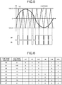
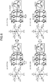
- FIG. 6 is a chart showing eight switching pattern examples in the present embodiment. Note that, in FIG. 6 , voltage vectors generated in the respective switching patterns are described as V0 to V7. The voltage directions of the respective voltage vectors are indicated by adding + or - to the names (U, V, and W) of the phases. When the voltage is not generated, the direction is represented by 0.
- +U means a voltage for generating an electric current in the U-phase direction, which flows into the motor 8 via the U-phase and flows out from the motor 8 via the V-phase and the W-phase
- -U means a voltage for generating an electric current in the -U-phase direction, which flows into the motor 8 via the V-phase and the W-phase and flows out from the motor 8 via the U-phase.
- +U means a voltage for generating an electric current in the U-phase direction, which flows into the motor 8 via the U-phase and flows out from the motor 8 via the V-phase and the W-phase
- -U means a voltage for generating an electric
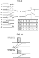
- the refrigerant drawn in from the main refrigerant circuit 58 (at point H in FIG. 13 ) is compressed to an intermediate pressure and heated (at point K in FIG. 13 ).
- the injection refrigerant joins the refrigerant compressed to the intermediate pressure and heated (at point K in FIG. 13 ), thereby decreasing the temperature (at point L in FIG. 13 ).
- the refrigerant having the decreased temperature (at point L in FIG. 13 ) is further compressed and heated to have a high temperature and a high pressure, and is discharged (at point A in FIG. 13 ).
Claims (10)
- Wärmepumpeneinrichtung (100), umfassend:einen Verdichter (1), umfassend einen ein Kältemittel komprimierenden Verdichtungsmechanismus (7) und einen den Verdichtungsmechanismus (7) antreibenden Motor (8);einen Inverter (9), der eingerichtet ist, eine Spannung zum Antreiben des Motors (8) anzulegen;einen Konverter (10), der eingerichtet ist, eine Spannung an den Inverter (9) anzulegen;eine Busspannungserfassungseinheit (11), die eingerichtet ist, eine Ausgangsspannung des Konverters (10) zu erfassen;eine Invertersteuerungseinheit (12), die eingerichtet ist, ein Antriebssignal zum Antreiben des Inverters (9) zu erzeugen, wobei die Invertersteuerungseinheit (12) ferner eingerichtet ist, einen Heizbetriebsmodus, in dem ein Heizbetrieb des Verdichters (1) durch Anlegen einer Hochfrequenz-Wechselstrom-Spannung an den Motor durchgeführt wird, und einen Normalbetriebsmodus, in dem ein Kältemittel durch Durchführen eines Normalbetriebs des Verdichters (1) verdichtet wird, zu umfassen; unddadurch gekennzeichnet, dasseine Konvertersteuerungseinheit (17) eingerichtet ist, ein Antriebssignal zum Antreiben des Konverters (10) auf Grundlage eines von der Inverstersteuerungseinheit (12) eingegebenen Signals und eines von der Busspannungserfassungseinheit (11) eingegebenen Signals (Vdc) zu erzeugen und das Antriebssignal an den Konverter (10) auszugeben, undim Heizbetriebsmodus der Invertersteuerungseinheit (12) die Konvertersteuerungseinheit (17) eingerichtet ist, den Konverter (10) anzuhalten, wenn eine an den Motor (8) gegebene Spannungsamplitude gleich oder größer ist als ein durch die Busspannungserfassungseinheit (11) erfasster Busspannungserfassungswert, und die an den Inverter (9) angelegte Spannung herunterzutransformieren, wenn die Spannungsamplitude kleiner ist als der Busspannungserfassungswert.
- Wärmepumpeneinrichtung (100) nach Anspruch 1, wobei die Invertersteuerungseinheit (12) in der Lage ist, mindestens eine einer Frequenz, einer Phase und einer Amplitude einer an den Motor (8) angelegten Hochfrequenz-Wechselstrom-Spannung im Heizbetriebsmodus der Inverstersteuerungseinheit einzustellen.
- Wärmepumpeneinrichtung (100) nach Anspruch 1 oder 2, wobei der Konverter (10) ein Abwärtskonverter ist, der eine an den Inverter (9) angelegte Busspannung heruntertransformiert, und
die Konvertersteuerungseinheit (17) eingerichtet ist, eine Korrespondenz zwischen einer an den Motor angelegten Spannung und einem Spannungsbefehlswert an die Busspannung zu bewahren und einen Spannungsbefehlswert an die Busspannung gemäß einer an den Motor angelegten Spannung auf Grundlage der Korrespondenz einzustellen. - Wärmepumpeneinrichtung (100) nach Anspruch 1, 2 oder 3, wobei die Konvertersteuerungseinheit (17) eingerichtet ist, die Steuerung so durchzuführen, dass ein Verhältnis einer an den Inverter (9) angelegten Spannung zu einer durch den Inverter an den Motor (8) angelegten Spannung auf 50% oder höher eingestellt wird.
- Wärmepumpeneinrichtung (100) nach einem der Ansprüche 1 bis 4, wobei mindestens eines der Schaltelemente (21a bis 21f), die den Inverter (9) einrichten, von einem Halbleiter mit weitem Bandabstand ausgebildet wird.
- Wärmepumpeneinrichtung (100) nach einem der Ansprüche 1 bis 5, wobei mindestens eine der Dioden von Schaltelementen (21a bis 21f), die den Inverter (9) einrichten, von einem Halbleiter mit weitem Bandabstand ausgebildet wird.
- Wärmepumpeneinrichtung (100) nach Anspruch 5 oder 6, wobei der Halbleiter mit weitem Bandabstand Siliziumcarbid, ein Galliumnitridmaterial oder Diamant ist.
- Wärmepumpeneinrichtung (100) nach einem der Ansprüche 1 bis 7, wobei, wenn eine Frequenz der Hochfrequenz-Wechselstrom-Spannung 10 Kilohertz überschreitet, die Eingangsleistung des Motors (8) auf 50 Watt oder weniger geregelt wird.
- Klimaanlage, umfassend die Wärmepumpeneinrichtung (100) nach einem der Ansprüche 1 bis 8.
- Gefriergerät, umfassend die Wärmepumpeneinrichtung (100) nach einem der Ansprüche 1 bis 8.
Applications Claiming Priority (1)
| Application Number | Priority Date | Filing Date | Title |
|---|---|---|---|
| PCT/JP2012/060296 WO2013157074A1 (ja) | 2012-04-16 | 2012-04-16 | ヒートポンプ装置、空気調和機および冷凍機 |
Publications (3)
| Publication Number | Publication Date |
|---|---|
| EP2851631A1 EP2851631A1 (de) | 2015-03-25 |
| EP2851631A4 EP2851631A4 (de) | 2016-02-24 |
| EP2851631B1 true EP2851631B1 (de) | 2020-03-11 |
Family
ID=49383064
Family Applications (1)
| Application Number | Title | Priority Date | Filing Date |
|---|---|---|---|
| EP12874570.0A Active EP2851631B1 (de) | 2012-04-16 | 2012-04-16 | Wärmepumpenvorrichtung, klimaanlage und kältemaschine |
Country Status (6)
| Country | Link |
|---|---|
| US (1) | US9739515B2 (de) |
| EP (1) | EP2851631B1 (de) |
| JP (1) | JP5901747B2 (de) |
| CN (1) | CN104220820B (de) |
| AU (1) | AU2012377681B2 (de) |
| WO (1) | WO2013157074A1 (de) |
Families Citing this family (18)
| Publication number | Priority date | Publication date | Assignee | Title |
|---|---|---|---|---|
| AU2010365997B2 (en) * | 2010-12-21 | 2015-03-26 | Mitsubishi Electric Corporation | Heat pump device, heat pump system, and method for controlling three-phase inverter |
| US10208991B2 (en) * | 2011-12-14 | 2019-02-19 | Mitsubishi Electric Corporation | Heat pump device, and air conditioner, heat pump water heater, refrigerator and freezing machine including heat pump device |
| JP2015084622A (ja) | 2013-10-25 | 2015-04-30 | 三菱重工オートモーティブサーマルシステムズ株式会社 | スイッチング素子の駆動装置及び駆動方法並びに車両用空調装置 |
| KR102173371B1 (ko) * | 2014-01-06 | 2020-11-03 | 엘지전자 주식회사 | 냉장고, 및 홈 어플라이언스 |
| KR102220911B1 (ko) * | 2014-01-06 | 2021-02-25 | 엘지전자 주식회사 | 냉장고, 및 홈 어플라이언스 |
| JP6217554B2 (ja) * | 2014-07-30 | 2017-10-25 | 株式会社豊田自動織機 | インバータ装置 |
| WO2016046993A1 (ja) * | 2014-09-26 | 2016-03-31 | 三菱電機株式会社 | ヒートポンプ装置ならびに、それを備えた空気調和機、ヒートポンプ給湯機、冷蔵庫、および冷凍機 |
| JP6476810B2 (ja) * | 2014-12-10 | 2019-03-06 | ダイキン工業株式会社 | 圧縮機の予熱装置 |
| JP6354623B2 (ja) * | 2015-03-05 | 2018-07-11 | 住友電気工業株式会社 | 変換装置 |
| WO2018067843A1 (en) | 2016-10-05 | 2018-04-12 | Johnson Controls Technology Company | Variable speed drive for a hvac&r system |
| CN107395090A (zh) * | 2017-06-22 | 2017-11-24 | 东南大学 | 一种用于单相直线斯特林电机的大功率高功率因数驱动控制器 |
| WO2019021450A1 (ja) * | 2017-07-28 | 2019-01-31 | 三菱電機株式会社 | 空気調和機、空調システム、及び空気調和機の制御方法 |
| US11211875B2 (en) * | 2017-09-08 | 2021-12-28 | Mitsubishi Electric Corporation | Power converter, compressor, air-sending device, and air-conditioning apparatus |
| US10670296B2 (en) * | 2017-11-02 | 2020-06-02 | Emerson Climate Technologies, Inc. | System and method of adjusting compressor modulation range based on balance point detection of the conditioned space |
| JP6963495B2 (ja) * | 2017-12-22 | 2021-11-10 | サンデンホールディングス株式会社 | 電力変換装置 |
| CN109217776B (zh) * | 2018-09-27 | 2020-10-20 | 深圳市英威腾电气股份有限公司 | 一种电机的加热方法、装置及变频器 |
| CN111854100A (zh) * | 2019-04-26 | 2020-10-30 | 青岛海尔空调器有限总公司 | 变频空调器的控制方法及装置和变频空调器 |
| CN113939699B (zh) * | 2019-05-28 | 2024-02-27 | 三菱电机株式会社 | 热泵装置、空调机以及制冷机 |
Family Cites Families (44)
| Publication number | Priority date | Publication date | Assignee | Title |
|---|---|---|---|---|
| JPS609436B2 (ja) * | 1980-08-29 | 1985-03-09 | 株式会社東芝 | 交流電動機の制御方法 |
| JPS6068341A (ja) | 1983-09-26 | 1985-04-18 | Canon Inc | リソグラフィ−用マスク構造体 |
| JPS6068341U (ja) | 1983-10-19 | 1985-05-15 | 株式会社東芝 | ヒ−トポンプ式空気調和機 |
| JPS6191445A (ja) | 1984-10-12 | 1986-05-09 | Matsushita Electric Ind Co Ltd | 空気調和機の圧縮機駆動装置 |
| US5272429A (en) * | 1990-10-01 | 1993-12-21 | Wisconsin Alumni Research Foundation | Air gap flux measurement using stator third harmonic voltage and uses |
| US5083039B1 (en) * | 1991-02-01 | 1999-11-16 | Zond Energy Systems Inc | Variable speed wind turbine |
| KR930010466B1 (ko) | 1991-02-26 | 1993-10-25 | 삼성전자 주식회사 | 냉난방겸용 공조기의 콤프레셔 기동 제어방법 |
| JPH0835712A (ja) * | 1994-07-26 | 1996-02-06 | Fujitsu General Ltd | 空気調和機の制御装置 |
| JPH08226714A (ja) | 1995-02-23 | 1996-09-03 | Matsushita Electric Ind Co Ltd | 空気調和機 |
| JP3298450B2 (ja) * | 1997-03-19 | 2002-07-02 | 株式会社日立製作所 | 空気調和機及び電力変換装置 |
| JPH11159467A (ja) | 1997-11-28 | 1999-06-15 | Zexel:Kk | 電動機予熱装置における通電制御方法及び電動機予熱装置 |
| TW528847B (en) * | 1998-06-18 | 2003-04-21 | Hitachi Ltd | Refrigerator |
| US6023420A (en) * | 1998-11-17 | 2000-02-08 | Creare, Inc. | Three-phase inverter for small high speed motors |
| JP4515573B2 (ja) | 1999-12-20 | 2010-08-04 | 澤藤電機株式会社 | 振動型圧縮機の駆動装置 |
| JP2004104895A (ja) * | 2002-09-09 | 2004-04-02 | Hitachi Ltd | 圧縮機駆動装置及び冷凍空調装置 |
| JP2002106909A (ja) | 2000-09-28 | 2002-04-10 | Matsushita Electric Ind Co Ltd | 空気調和機 |
| JP2004271167A (ja) | 2003-02-19 | 2004-09-30 | Matsushita Electric Ind Co Ltd | 空気調和装置 |
| EP1617551A4 (de) * | 2003-04-22 | 2010-09-08 | Panasonic Corp | Motorregeleinrichtung, kompressor, klimaanlage und kühlschrank |
| JP4529540B2 (ja) * | 2004-05-13 | 2010-08-25 | パナソニック株式会社 | 空気調和装置と圧縮機の予熱方法 |
| US20080041081A1 (en) * | 2006-08-15 | 2008-02-21 | Bristol Compressors, Inc. | System and method for compressor capacity modulation in a heat pump |
| JP2007162978A (ja) * | 2005-12-12 | 2007-06-28 | Matsushita Electric Ind Co Ltd | 空気調和機の圧縮機駆動装置 |
| JP4640152B2 (ja) | 2005-12-13 | 2011-03-02 | 三菱電機株式会社 | 空気調和機用圧縮機の駆動制御装置 |
| JP4079178B2 (ja) * | 2006-04-19 | 2008-04-23 | ダイキン工業株式会社 | 電力変換器及びその制御方法並びに空気調和機 |
| KR100851905B1 (ko) * | 2007-03-28 | 2008-08-13 | 삼성전자주식회사 | 압축기의 예열 제어 장치 및 방법 |
| JP4512145B2 (ja) * | 2008-03-21 | 2010-07-28 | ファナック株式会社 | モータ制御装置 |
| US8790089B2 (en) * | 2008-06-29 | 2014-07-29 | Bristol Compressors International, Inc. | Compressor speed control system for bearing reliability |
| US8336323B2 (en) * | 2008-10-03 | 2012-12-25 | Johnson Controls Technology Company | Variable speed drive with pulse-width modulated speed control |
| US8866331B2 (en) * | 2008-10-24 | 2014-10-21 | Honda Motor Co., Ltd. | Power supply device and power supply system for fuel cell vehicle |
| JP4512671B1 (ja) * | 2008-12-17 | 2010-07-28 | パナソニック株式会社 | 電力変換回路 |
| JP5195444B2 (ja) * | 2009-01-14 | 2013-05-08 | パナソニック株式会社 | ブラシレスdcモータの駆動装置並びにこれを用いた冷蔵庫及び空気調和機 |
| WO2010143758A1 (ko) * | 2009-06-10 | 2010-12-16 | 엘지전자 주식회사 | 분산전원을 이용한 공기조화기의 전동기 제어장치 |
| JP2011002190A (ja) | 2009-06-19 | 2011-01-06 | Daikin Industries Ltd | 冷凍装置 |
| JP4985723B2 (ja) | 2009-07-27 | 2012-07-25 | 三菱電機株式会社 | 空気調和機 |
| JP4931970B2 (ja) | 2009-08-10 | 2012-05-16 | 三菱電機株式会社 | 空気調和機 |
| KR101507212B1 (ko) * | 2009-09-28 | 2015-03-30 | 다이킨 고교 가부시키가이샤 | 상전류 검출장치, 및 이를 이용한 전력변환장치 |
| WO2011074145A1 (ja) * | 2009-12-17 | 2011-06-23 | 三菱電機株式会社 | 空気調和機 |
| JP5506412B2 (ja) | 2010-01-12 | 2014-05-28 | 三菱電機株式会社 | 空気調和機用の圧縮機駆動制御装置 |
| US9129885B2 (en) * | 2010-01-15 | 2015-09-08 | Mitsubishi Electric Corporation | Power semiconductor module |
| JP5577714B2 (ja) * | 2010-01-21 | 2014-08-27 | トヨタ自動車株式会社 | 交流モータの制御装置 |
| JP5175887B2 (ja) * | 2010-03-23 | 2013-04-03 | 株式会社東芝 | モータ制御装置及び電気機器 |
| JP5308474B2 (ja) * | 2010-05-06 | 2013-10-09 | ダイキン工業株式会社 | 冷凍装置 |
| EP2613106B1 (de) | 2010-08-30 | 2015-09-23 | Mitsubishi Electric Corporation | Wärmepumpenvorrcihtung, wärmepumpensystem und verfahren zur steuerung eines dreiphasenwandlers |
| JP5490249B2 (ja) | 2010-10-15 | 2014-05-14 | 三菱電機株式会社 | ヒートポンプ装置、ヒートポンプシステム及びインバータの制御方法 |
| AU2010365997B2 (en) | 2010-12-21 | 2015-03-26 | Mitsubishi Electric Corporation | Heat pump device, heat pump system, and method for controlling three-phase inverter |
-
2012
- 2012-04-16 US US14/388,266 patent/US9739515B2/en active Active
- 2012-04-16 AU AU2012377681A patent/AU2012377681B2/en active Active
- 2012-04-16 WO PCT/JP2012/060296 patent/WO2013157074A1/ja active Application Filing
- 2012-04-16 CN CN201280072410.6A patent/CN104220820B/zh active Active
- 2012-04-16 EP EP12874570.0A patent/EP2851631B1/de active Active
- 2012-04-16 JP JP2014510988A patent/JP5901747B2/ja active Active
Non-Patent Citations (1)
| Title |
|---|
| None * |
Also Published As
| Publication number | Publication date |
|---|---|
| EP2851631A1 (de) | 2015-03-25 |
| JP5901747B2 (ja) | 2016-04-13 |
| US20150089972A1 (en) | 2015-04-02 |
| AU2012377681A1 (en) | 2014-10-30 |
| JPWO2013157074A1 (ja) | 2015-12-21 |
| AU2012377681B2 (en) | 2015-12-10 |
| EP2851631A4 (de) | 2016-02-24 |
| US9739515B2 (en) | 2017-08-22 |
| CN104220820B (zh) | 2016-03-30 |
| CN104220820A (zh) | 2014-12-17 |
| WO2013157074A1 (ja) | 2013-10-24 |
Similar Documents
| Publication | Publication Date | Title |
|---|---|---|
| EP2851631B1 (de) | Wärmepumpenvorrichtung, klimaanlage und kältemaschine | |
| EP2884203B1 (de) | Wärmepumpenvorrichtung | |
| EP2763303B1 (de) | Wärmepumpvorrichtung, wärmepumpensystem und umrichtersteuerungsverfahren | |
| EP2803922B1 (de) | Wärmepumpvorrichtung, klimaanlage und kühlschrank | |
| EP2703748B1 (de) | Wärmepumpenvorrichtung und verfahren zur steuerung eines wechselrichters in einer wärmepumpenvorrichtung | |
| JP5693617B2 (ja) | ヒートポンプ装置、ヒートポンプシステム及び三相インバータの制御方法 | |
| US9903629B2 (en) | Heat pump device, air conditioner, and freezer | |
| EP2657626B1 (de) | Wärmepumpenvorrichtung, wärmepumpensystem und verfahren zur steuerung eines dreiphasenwandlers | |
| US10281185B2 (en) | Motor driving device, and heat pump device and refrigerating and air conditioning device using the motor driving device | |
| US11114970B2 (en) | Motor driver, heat pump system and refrigeration and air conditioning equipment using motor driver | |
| US10033325B2 (en) | Heat pump device, and air conditioner, heat pump water heater, refrigerator, and freezing machine that includes heat pump device |
Legal Events
| Date | Code | Title | Description |
|---|---|---|---|
| PUAI | Public reference made under article 153(3) epc to a published international application that has entered the european phase |
Free format text: ORIGINAL CODE: 0009012 |
|
| 17P | Request for examination filed |
Effective date: 20141030 |
|
| AK | Designated contracting states |
Kind code of ref document: A1 Designated state(s): AL AT BE BG CH CY CZ DE DK EE ES FI FR GB GR HR HU IE IS IT LI LT LU LV MC MK MT NL NO PL PT RO RS SE SI SK SM TR |
|
| AX | Request for extension of the european patent |
Extension state: BA ME |
|
| DAX | Request for extension of the european patent (deleted) | ||
| RA4 | Supplementary search report drawn up and despatched (corrected) |
Effective date: 20160121 |
|
| RIC1 | Information provided on ipc code assigned before grant |
Ipc: F25B 13/00 20060101ALI20160115BHEP Ipc: H02M 1/00 20060101ALI20160115BHEP Ipc: F25B 1/00 20060101AFI20160115BHEP Ipc: F24F 11/02 20060101ALI20160115BHEP Ipc: F04C 29/04 20060101ALI20160115BHEP Ipc: F04C 28/06 20060101ALI20160115BHEP Ipc: F25B 49/02 20060101ALI20160115BHEP Ipc: H02M 7/48 20070101ALI20160115BHEP Ipc: H02M 3/155 20060101ALI20160115BHEP Ipc: H02M 7/5387 20070101ALI20160115BHEP |
|
| STAA | Information on the status of an ep patent application or granted ep patent |
Free format text: STATUS: EXAMINATION IS IN PROGRESS |
|
| 17Q | First examination report despatched |
Effective date: 20170223 |
|
| RIC1 | Information provided on ipc code assigned before grant |
Ipc: H02M 1/00 20060101ALI20190802BHEP Ipc: F04C 29/04 20060101ALI20190802BHEP Ipc: F25B 1/00 20060101AFI20190802BHEP Ipc: H02M 7/5387 20070101ALI20190802BHEP Ipc: F04C 28/06 20060101ALI20190802BHEP Ipc: H02M 7/48 20070101ALI20190802BHEP Ipc: F25B 13/00 20060101ALI20190802BHEP Ipc: H02M 3/155 20060101ALI20190802BHEP Ipc: F25B 49/02 20060101ALI20190802BHEP |
|
| GRAP | Despatch of communication of intention to grant a patent |
Free format text: ORIGINAL CODE: EPIDOSNIGR1 |
|
| STAA | Information on the status of an ep patent application or granted ep patent |
Free format text: STATUS: GRANT OF PATENT IS INTENDED |
|
| INTG | Intention to grant announced |
Effective date: 20190924 |
|
| GRAS | Grant fee paid |
Free format text: ORIGINAL CODE: EPIDOSNIGR3 |
|
| GRAA | (expected) grant |
Free format text: ORIGINAL CODE: 0009210 |
|
| STAA | Information on the status of an ep patent application or granted ep patent |
Free format text: STATUS: THE PATENT HAS BEEN GRANTED |
|
| AK | Designated contracting states |
Kind code of ref document: B1 Designated state(s): AL AT BE BG CH CY CZ DE DK EE ES FI FR GB GR HR HU IE IS IT LI LT LU LV MC MK MT NL NO PL PT RO RS SE SI SK SM TR |
|
| REG | Reference to a national code |
Ref country code: GB Ref legal event code: FG4D |
|
| REG | Reference to a national code |
Ref country code: CH Ref legal event code: EP |
|
| REG | Reference to a national code |
Ref country code: AT Ref legal event code: REF Ref document number: 1243613 Country of ref document: AT Kind code of ref document: T Effective date: 20200315 |
|
| REG | Reference to a national code |
Ref country code: IE Ref legal event code: FG4D |
|
| REG | Reference to a national code |
Ref country code: DE Ref legal event code: R096 Ref document number: 602012068466 Country of ref document: DE |
|
| PG25 | Lapsed in a contracting state [announced via postgrant information from national office to epo] |
Ref country code: NO Free format text: LAPSE BECAUSE OF FAILURE TO SUBMIT A TRANSLATION OF THE DESCRIPTION OR TO PAY THE FEE WITHIN THE PRESCRIBED TIME-LIMIT Effective date: 20200611 Ref country code: FI Free format text: LAPSE BECAUSE OF FAILURE TO SUBMIT A TRANSLATION OF THE DESCRIPTION OR TO PAY THE FEE WITHIN THE PRESCRIBED TIME-LIMIT Effective date: 20200311 Ref country code: RS Free format text: LAPSE BECAUSE OF FAILURE TO SUBMIT A TRANSLATION OF THE DESCRIPTION OR TO PAY THE FEE WITHIN THE PRESCRIBED TIME-LIMIT Effective date: 20200311 |
|
| REG | Reference to a national code |
Ref country code: NL Ref legal event code: MP Effective date: 20200311 |
|
| PG25 | Lapsed in a contracting state [announced via postgrant information from national office to epo] |
Ref country code: LV Free format text: LAPSE BECAUSE OF FAILURE TO SUBMIT A TRANSLATION OF THE DESCRIPTION OR TO PAY THE FEE WITHIN THE PRESCRIBED TIME-LIMIT Effective date: 20200311 Ref country code: SE Free format text: LAPSE BECAUSE OF FAILURE TO SUBMIT A TRANSLATION OF THE DESCRIPTION OR TO PAY THE FEE WITHIN THE PRESCRIBED TIME-LIMIT Effective date: 20200311 Ref country code: HR Free format text: LAPSE BECAUSE OF FAILURE TO SUBMIT A TRANSLATION OF THE DESCRIPTION OR TO PAY THE FEE WITHIN THE PRESCRIBED TIME-LIMIT Effective date: 20200311 Ref country code: BG Free format text: LAPSE BECAUSE OF FAILURE TO SUBMIT A TRANSLATION OF THE DESCRIPTION OR TO PAY THE FEE WITHIN THE PRESCRIBED TIME-LIMIT Effective date: 20200611 Ref country code: GR Free format text: LAPSE BECAUSE OF FAILURE TO SUBMIT A TRANSLATION OF THE DESCRIPTION OR TO PAY THE FEE WITHIN THE PRESCRIBED TIME-LIMIT Effective date: 20200612 |
|
| REG | Reference to a national code |
Ref country code: LT Ref legal event code: MG4D |
|
| PG25 | Lapsed in a contracting state [announced via postgrant information from national office to epo] |
Ref country code: NL Free format text: LAPSE BECAUSE OF FAILURE TO SUBMIT A TRANSLATION OF THE DESCRIPTION OR TO PAY THE FEE WITHIN THE PRESCRIBED TIME-LIMIT Effective date: 20200311 |
|
| PG25 | Lapsed in a contracting state [announced via postgrant information from national office to epo] |
Ref country code: SM Free format text: LAPSE BECAUSE OF FAILURE TO SUBMIT A TRANSLATION OF THE DESCRIPTION OR TO PAY THE FEE WITHIN THE PRESCRIBED TIME-LIMIT Effective date: 20200311 Ref country code: EE Free format text: LAPSE BECAUSE OF FAILURE TO SUBMIT A TRANSLATION OF THE DESCRIPTION OR TO PAY THE FEE WITHIN THE PRESCRIBED TIME-LIMIT Effective date: 20200311 Ref country code: CZ Free format text: LAPSE BECAUSE OF FAILURE TO SUBMIT A TRANSLATION OF THE DESCRIPTION OR TO PAY THE FEE WITHIN THE PRESCRIBED TIME-LIMIT Effective date: 20200311 Ref country code: LT Free format text: LAPSE BECAUSE OF FAILURE TO SUBMIT A TRANSLATION OF THE DESCRIPTION OR TO PAY THE FEE WITHIN THE PRESCRIBED TIME-LIMIT Effective date: 20200311 Ref country code: RO Free format text: LAPSE BECAUSE OF FAILURE TO SUBMIT A TRANSLATION OF THE DESCRIPTION OR TO PAY THE FEE WITHIN THE PRESCRIBED TIME-LIMIT Effective date: 20200311 Ref country code: PT Free format text: LAPSE BECAUSE OF FAILURE TO SUBMIT A TRANSLATION OF THE DESCRIPTION OR TO PAY THE FEE WITHIN THE PRESCRIBED TIME-LIMIT Effective date: 20200805 Ref country code: SK Free format text: LAPSE BECAUSE OF FAILURE TO SUBMIT A TRANSLATION OF THE DESCRIPTION OR TO PAY THE FEE WITHIN THE PRESCRIBED TIME-LIMIT Effective date: 20200311 Ref country code: IS Free format text: LAPSE BECAUSE OF FAILURE TO SUBMIT A TRANSLATION OF THE DESCRIPTION OR TO PAY THE FEE WITHIN THE PRESCRIBED TIME-LIMIT Effective date: 20200711 |
|
| REG | Reference to a national code |
Ref country code: AT Ref legal event code: MK05 Ref document number: 1243613 Country of ref document: AT Kind code of ref document: T Effective date: 20200311 |
|
| REG | Reference to a national code |
Ref country code: CH Ref legal event code: PL |
|
| REG | Reference to a national code |
Ref country code: DE Ref legal event code: R097 Ref document number: 602012068466 Country of ref document: DE |
|
| PG25 | Lapsed in a contracting state [announced via postgrant information from national office to epo] |
Ref country code: MC Free format text: LAPSE BECAUSE OF FAILURE TO SUBMIT A TRANSLATION OF THE DESCRIPTION OR TO PAY THE FEE WITHIN THE PRESCRIBED TIME-LIMIT Effective date: 20200311 |
|
| PLBE | No opposition filed within time limit |
Free format text: ORIGINAL CODE: 0009261 |
|
| STAA | Information on the status of an ep patent application or granted ep patent |
Free format text: STATUS: NO OPPOSITION FILED WITHIN TIME LIMIT |
|
| PG25 | Lapsed in a contracting state [announced via postgrant information from national office to epo] |
Ref country code: ES Free format text: LAPSE BECAUSE OF FAILURE TO SUBMIT A TRANSLATION OF THE DESCRIPTION OR TO PAY THE FEE WITHIN THE PRESCRIBED TIME-LIMIT Effective date: 20200311 Ref country code: AT Free format text: LAPSE BECAUSE OF FAILURE TO SUBMIT A TRANSLATION OF THE DESCRIPTION OR TO PAY THE FEE WITHIN THE PRESCRIBED TIME-LIMIT Effective date: 20200311 Ref country code: LU Free format text: LAPSE BECAUSE OF NON-PAYMENT OF DUE FEES Effective date: 20200416 Ref country code: IT Free format text: LAPSE BECAUSE OF FAILURE TO SUBMIT A TRANSLATION OF THE DESCRIPTION OR TO PAY THE FEE WITHIN THE PRESCRIBED TIME-LIMIT Effective date: 20200311 Ref country code: DK Free format text: LAPSE BECAUSE OF FAILURE TO SUBMIT A TRANSLATION OF THE DESCRIPTION OR TO PAY THE FEE WITHIN THE PRESCRIBED TIME-LIMIT Effective date: 20200311 Ref country code: CH Free format text: LAPSE BECAUSE OF NON-PAYMENT OF DUE FEES Effective date: 20200430 Ref country code: LI Free format text: LAPSE BECAUSE OF NON-PAYMENT OF DUE FEES Effective date: 20200430 |
|
| REG | Reference to a national code |
Ref country code: BE Ref legal event code: MM Effective date: 20200430 |
|
| 26N | No opposition filed |
Effective date: 20201214 |
|
| PG25 | Lapsed in a contracting state [announced via postgrant information from national office to epo] |
Ref country code: BE Free format text: LAPSE BECAUSE OF NON-PAYMENT OF DUE FEES Effective date: 20200430 Ref country code: PL Free format text: LAPSE BECAUSE OF FAILURE TO SUBMIT A TRANSLATION OF THE DESCRIPTION OR TO PAY THE FEE WITHIN THE PRESCRIBED TIME-LIMIT Effective date: 20200311 Ref country code: SI Free format text: LAPSE BECAUSE OF FAILURE TO SUBMIT A TRANSLATION OF THE DESCRIPTION OR TO PAY THE FEE WITHIN THE PRESCRIBED TIME-LIMIT Effective date: 20200311 |
|
| PG25 | Lapsed in a contracting state [announced via postgrant information from national office to epo] |
Ref country code: IE Free format text: LAPSE BECAUSE OF NON-PAYMENT OF DUE FEES Effective date: 20200416 |
|
| PG25 | Lapsed in a contracting state [announced via postgrant information from national office to epo] |
Ref country code: TR Free format text: LAPSE BECAUSE OF FAILURE TO SUBMIT A TRANSLATION OF THE DESCRIPTION OR TO PAY THE FEE WITHIN THE PRESCRIBED TIME-LIMIT Effective date: 20200311 Ref country code: MT Free format text: LAPSE BECAUSE OF FAILURE TO SUBMIT A TRANSLATION OF THE DESCRIPTION OR TO PAY THE FEE WITHIN THE PRESCRIBED TIME-LIMIT Effective date: 20200311 Ref country code: CY Free format text: LAPSE BECAUSE OF FAILURE TO SUBMIT A TRANSLATION OF THE DESCRIPTION OR TO PAY THE FEE WITHIN THE PRESCRIBED TIME-LIMIT Effective date: 20200311 |
|
| PG25 | Lapsed in a contracting state [announced via postgrant information from national office to epo] |
Ref country code: MK Free format text: LAPSE BECAUSE OF FAILURE TO SUBMIT A TRANSLATION OF THE DESCRIPTION OR TO PAY THE FEE WITHIN THE PRESCRIBED TIME-LIMIT Effective date: 20200311 Ref country code: AL Free format text: LAPSE BECAUSE OF FAILURE TO SUBMIT A TRANSLATION OF THE DESCRIPTION OR TO PAY THE FEE WITHIN THE PRESCRIBED TIME-LIMIT Effective date: 20200311 |
|
| PGFP | Annual fee paid to national office [announced via postgrant information from national office to epo] |
Ref country code: FR Payment date: 20230309 Year of fee payment: 12 |
|
| P01 | Opt-out of the competence of the unified patent court (upc) registered |
Effective date: 20230512 |
|
| REG | Reference to a national code |
Ref country code: DE Ref legal event code: R084 Ref document number: 602012068466 Country of ref document: DE |
|
| PGFP | Annual fee paid to national office [announced via postgrant information from national office to epo] |
Ref country code: DE Payment date: 20230228 Year of fee payment: 12 |
|
| REG | Reference to a national code |
Ref country code: GB Ref legal event code: 746 Effective date: 20240328 |
|
| PGFP | Annual fee paid to national office [announced via postgrant information from national office to epo] |
Ref country code: GB Payment date: 20240229 Year of fee payment: 13 |