EP2851469A1 - Improved self-locking concrete tile - Google Patents
Improved self-locking concrete tile Download PDFInfo
- Publication number
- EP2851469A1 EP2851469A1 EP14306313.9A EP14306313A EP2851469A1 EP 2851469 A1 EP2851469 A1 EP 2851469A1 EP 14306313 A EP14306313 A EP 14306313A EP 2851469 A1 EP2851469 A1 EP 2851469A1
- Authority
- EP
- European Patent Office
- Prior art keywords
- vertical
- spacers
- block
- edge
- transverse
- Prior art date
- Legal status (The legal status is an assumption and is not a legal conclusion. Google has not performed a legal analysis and makes no representation as to the accuracy of the status listed.)
- Granted
Links
- 125000006850 spacer group Chemical group 0.000 claims abstract description 64
- 210000002105 tongue Anatomy 0.000 claims abstract description 34
- 239000004576 sand Substances 0.000 claims description 20
- 238000007906 compression Methods 0.000 claims description 4
- 230000000903 blocking effect Effects 0.000 description 5
- 230000000694 effects Effects 0.000 description 5
- 230000015572 biosynthetic process Effects 0.000 description 4
- 238000009434 installation Methods 0.000 description 4
- 230000006835 compression Effects 0.000 description 3
- 238000007665 sagging Methods 0.000 description 3
- 238000006073 displacement reaction Methods 0.000 description 2
- 238000004519 manufacturing process Methods 0.000 description 2
- 238000000465 moulding Methods 0.000 description 2
- 239000003351 stiffener Substances 0.000 description 2
- 239000004575 stone Substances 0.000 description 2
- 230000001154 acute effect Effects 0.000 description 1
- 230000000295 complement effect Effects 0.000 description 1
- 230000003247 decreasing effect Effects 0.000 description 1
- 230000001687 destabilization Effects 0.000 description 1
- 230000006866 deterioration Effects 0.000 description 1
- 230000003628 erosive effect Effects 0.000 description 1
- 230000001939 inductive effect Effects 0.000 description 1
- 230000000670 limiting effect Effects 0.000 description 1
- 238000000034 method Methods 0.000 description 1
- 230000005012 migration Effects 0.000 description 1
- 238000013508 migration Methods 0.000 description 1
- 238000012986 modification Methods 0.000 description 1
- 230000004048 modification Effects 0.000 description 1
- 230000036961 partial effect Effects 0.000 description 1
- 230000035515 penetration Effects 0.000 description 1
- 230000000737 periodic effect Effects 0.000 description 1
- 230000000750 progressive effect Effects 0.000 description 1
- 230000000284 resting effect Effects 0.000 description 1
- 238000005488 sandblasting Methods 0.000 description 1
- 238000000926 separation method Methods 0.000 description 1
- 230000006641 stabilisation Effects 0.000 description 1
- 238000011105 stabilization Methods 0.000 description 1
- 238000006467 substitution reaction Methods 0.000 description 1
- 230000000007 visual effect Effects 0.000 description 1
- XLYOFNOQVPJJNP-UHFFFAOYSA-N water Substances O XLYOFNOQVPJJNP-UHFFFAOYSA-N 0.000 description 1
Images

Classifications
-
- E—FIXED CONSTRUCTIONS
- E01—CONSTRUCTION OF ROADS, RAILWAYS, OR BRIDGES
- E01C—CONSTRUCTION OF, OR SURFACES FOR, ROADS, SPORTS GROUNDS, OR THE LIKE; MACHINES OR AUXILIARY TOOLS FOR CONSTRUCTION OR REPAIR
- E01C5/00—Pavings made of prefabricated single units
- E01C5/06—Pavings made of prefabricated single units made of units with cement or like binders
-
- E—FIXED CONSTRUCTIONS
- E01—CONSTRUCTION OF ROADS, RAILWAYS, OR BRIDGES
- E01C—CONSTRUCTION OF, OR SURFACES FOR, ROADS, SPORTS GROUNDS, OR THE LIKE; MACHINES OR AUXILIARY TOOLS FOR CONSTRUCTION OR REPAIR
- E01C2201/00—Paving elements
- E01C2201/02—Paving elements having fixed spacing features
Definitions
- the present invention relates to the field of the road surfacing industry and the like, in particular concrete pavers and relates to a block of self-locking concrete.
- Such pavers are generally provided with interlocking means allowing their locking in two directions in the horizontal plane, these means being often geometric shapes provided on the edges of said pavers and having an inverse symmetry between the parallel edges of the pavers.
- the known pavers are equipped with spacers elements also provided on their edges and to ensure the formation of a separation seal to be filled by a sand filling.
- the known pavers make it possible to respond relatively correctly to the requirements for blocking and anti-dislodging out of a laid surface in cases where very strict circulation criteria can be fulfilled, namely relatively low speeds of movement generating very weak vibrations.
- the existing pavers, self-locking type or not have perfectly vertical edges, as well as the spacers with which they are equipped, so that the grouting sand only allows to achieve, by vibration, an effective blocking, following both directions in the horizontal plane.
- EP-A-1,036,882 describes a type of block similar to that described in the previous document and calls the same remarks. This block also does not allow to obtain a resistance "anti-pulling", the spacers being only intended to ensure positioning during installation and destroying during the vibration of the laid surface.
- DE-U-297 21 360 discloses a block provided with locking means, but without interpenetration, wherein the spacing elements are only provided on a part of the height from the base, thus ensuring a uniform apparent seal does not appear said distancers.
- Such a block makes it possible to largely obviate the majority of the disadvantages of the pavers existing to date, but can not guarantee for a long time an absolute locking against tearing, due to possible wear of the spacers at their contact points causing a migration of grouting sand to the laying bed and thus a game between neighboring blocks.
- EP-A-2,527,533 a block of self-locking concrete, provided on its longitudinal and transverse edges means distance, arranged on both sides of spacers.
- This block has polygonal base-shaped pyramidal trunk spacers that cooperate, in shape, with the base of the spacing means of the neighboring blocks, during the interpenetration of the blocks in the laying position, and the spacers are arranged in the median vertical axis of the means spacers, have a form of half-truncated cone or half-truncated pyramid, whose large base extends at the polygonal base of the corresponding spacing means, partially projecting relative thereto, each spacer cooperating with a corresponding vertical recess, provided in the edge of the neighboring block and whose section is equal to that of the large base of the spacer and constant over the entire height of the block.
- Such a block of self-locking concrete ensures a self-locking position, both in the plane of the laying surface perpendicular to this plane, that is to say, avoiding tearing in traffic conditions.
- the subject of the present invention is a self-locking concrete paver which, like the paving stone according to EP-A-2,527,533 on the one hand, to simultaneously ensure self-locking in both directions of the horizontal laying plane, as well as locking in position against tearing, by eliminating any play between blocks and, on the other hand, to achieve a linear continuity of the joints, while being a simple implementation and manufacturing.
- the block of self-locking concrete provided on its longitudinal and transverse edges with means spacers, arranged on either side of spacers said spacers being arranged between the means and spacers cooperating, by form, with said means distancers neighboring blocks, during the interpenetration of the pavers in the laying position, is characterized in that the distance means are each constituted by a pair of vertical tabs with a polygonal base or a portion of a circle projecting from the edge of the pavement and whose apex is in the form of a truncated pyramid or portion of a truncated cone, and in that said vertical tongues delimit between them, on the edge of the pavement, a vertical recess of constant section and of receiving a corresponding spacer protruding on the edge of the neighboring pavement
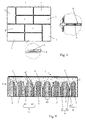
- FIGS. 1 and 2 appended drawings are a self-blocking paver 1 made of concrete intended to be laid on traffic lanes, parking areas or other.
- This block 1 is provided on its longitudinal edges 2 and transverse 3 with distance means 4, arranged on either side of spacers 5, arranged between the distance means 4 and cooperating, by form, with said means 4 spacers neighboring blocks, during the interpenetration of the pavers in the laying position ( figure 4 ).
- the distance means 4 are each constituted by a pair of vertical tongues 41 having a polygonal base or a portion of a circle projecting from the edge of the pavement and whose apex is in the form of a truncated pyramid or portion of truncated cone, and in that said vertical tabs 41 delimit between them, on the edge of the block 1, a vertical recess 42 of constant section and receiving a corresponding spacer 5, projecting from the edge of the block neighbour ( Figures 1 to 4 ).
- the distance means 4 and the spacers 5 are arranged on said longitudinal and transverse edges 2 3 in inverse symmetry, respectively with respect to the transverse central axis and the longitudinal median axis.
- a paver apparatus 1 by which the transverse edges and the longitudinal edges of pavers 1 adjacent by their longitudinal edges and by their transverse edges are perfectly aligned ( figure 4 ).
- this arrangement also allows a staggered laying, with longitudinal offset of the blocks 1, and a laying at right angles, a block 1 being arranged perpendicularly to another block 1, with alignment of the longitudinal edge of the one with the transverse edge of the other.
- This arrangement of the pavers 1 is ensured by the cooperation of the spacers 5 with the corresponding vertical recesses 42 delimited between the vertical tongues 41 constituting the spacing means 4 of the neighboring blocks, as shown in FIG. figure 4 attached drawings. It results from this interpenetration that each distance means 4 is in contact, by the vertical tongues 41, on the one hand, with a spacer 5 and, on the other hand, with a longitudinal edge 2 or transverse 3 of a neighboring block 1 .
- This arrangement of the spacing means 4 and the spacers 5, projecting on the transverse edges 3 and the longitudinal edges 2 of the blocks 1 makes it possible to obtain a linear continuity of the joints between the blocks 1, said spacer means 4 and spacers 5 s extending entirely into the jointing space between pavers 1.
- the gap 7 delimited between the truncated pyramid-shaped peaks or truncated cone portion of the tongues 41 defines a corner filled with grouting sand preventing tearing of pavers 1 laid.
- the distance means 4 and the spacers 5 advantageously have a height less than that of the block 1, their vertex preferably extending below the level of the upper edge of said block 1.
- At least one spacer 5 of each longitudinal edge 2 and transverse 3 has a degressive section from the base of the block 1 to the upper end of the spacer 5, thus determining, with the vertical recess 42 delimited between the vertical tongues 41 of the corresponding spacing means 4, a vertical gap 6 'forming a grouting space by sand, with a progressive section from the lower face of the blocks 1 towards their upper face, producing a self compression under a pulling or sagging effort.
- the filling of grouting sand not only achieves a stabilization of the blocks in the horizontal plane, but also forms a means of self-locking in cooperation with the distance means 4 and the spacers 5.
- this self-locking means results from the fact that an attempt to tear off a block has the effect of inducing a displacement of the grouting sand at the spacers 5 and distance means 4, which has the effect a simultaneous compression of the grouting sand, this compression being effected, in fact, in cascade and resulting in a total blocking preventing tearing.
- the blocks 1 can not move in a horizontal plane, because, on the one hand, the interpenetration of the distance means 4 and spacers 5 and, on the other hand, because of the filling of vertical interstices 6 by the grouting sand, which prevent pivoting of the blocks 1 relative to each other and, in this way, tearing or sagging, especially mechanically.
- the block 1 is provided, on at least two opposite faces of the longitudinal edges 2 and / or transverse 3, at least one distance means 4 ', at least one vertical tongue 41' is shorter than the vertical tongues 41 of the means 4 spacers and whose apex extends to a level lower than that of the vertical tongues 41, determining a corresponding vertical gap 7 'between the vertical tongue 41 of the means spacer 4 previous and that (tab) 41', of the distance means 4 '.
- a distance means 4 'of smaller height is advantageously provided at one end of each longitudinal and transverse edge 3 3, the corresponding end of the transverse edge 3 and longitudinal 2 being provided with a succession of spacers 5 and means distance 4 ( Figures 1, 3 and 5 ).
- the figure 5 represents, hatched, the distance means 4 and 4 ', and the stiffeners 5 of a block, while the spacer means 4 and 4' and the stiffeners 5 of the other block are shown with a grid mark. The difference in height between the tongue 41 'of the distance means 4' and that of the tongue 41 adjacent is thus very clearly visible.
- At least one tongue 41 'of a block cooperates with a tongue 41 of the neighboring associated block.
- the top of the tongue 41 stopping at a level higher than that of the tongue 41 'thus leaving a larger rectangular base forms a kind of asymmetrical funnel for the flow of grouting sand.
- this block can be achieved by implementing the usual molding techniques, that is to say with the use of a single mold, monobloc, and the pose is also achievable simply and quickly.
Landscapes
- Engineering & Computer Science (AREA)
- Architecture (AREA)
- Civil Engineering (AREA)
- Structural Engineering (AREA)
- Road Paving Structures (AREA)
Abstract
La présente invention a pour objet un pavé en béton autobloquant (1), pourvu sur ses bords longitudinaux (2) et transversaux (3) de moyens distanceurs (4), disposés de part et d'autre d'écarteurs (5) disposés entre les moyens distanceurs (4) et coopérant, par forme, avec lesdits moyens distanceurs (4) des pavés voisins, lors de l'interpénétration des pavés en position de pose. Ledit pavé (1) est caractérisé en ce que les moyens distanceurs (4) sont constitués, chacun, par une paire de languettes verticales à base polygonale ou en portion de cercle, en saillie sur le bord du pavé et dont le sommet est en forme de tronc de pyramide ou de portion de tronc de cône, et en ce que lesdites languettes verticales délimitent entre elles un évidement vertical de section constante et de réception d'un écarteur (5) correspondant en saillie sur le bord du pavé voisin. En plus, il est pourvu, sur au moins deux faces opposées des bords longitudinaux (2) et/ou transversaux (3), d'au moins un moyen distanceur (4'), dont au moins une languette verticale (41') est plus courte que les languettes verticales (41) des moyens distanceurs (4) et dont le sommet s'étend à un niveau inférieur à celui des languettes verticales (41), déterminant un interstice vertical correspondant (7') entre la languette verticale (41) du moyen distanceur (4) précédent et celle (41') du moyen distanceur (4').The present invention relates to a block of self-locking concrete (1), provided on its longitudinal edges (2) and transverse (3) means spacers (4), arranged on both sides of spacers (5) arranged between the means spacers (4) and cooperating, by shape, with said means spacers (4) of neighboring blocks, during the interpenetration of the pavers in laying position. Said tile (1) is characterized in that the distance means (4) are each constituted by a pair of vertical tabs with a polygonal base or a portion of a circle, projecting from the edge of the tile and whose apex is shaped truncated pyramid or portion of truncated cone, and in that said vertical tabs delimit between them a vertical recess of constant section and receiving a spacer (5) corresponding projecting on the edge of the neighboring block. In addition, it is provided, on at least two opposite sides of the longitudinal edges (2) and / or transverse (3), of at least one distance means (4 '), at least one vertical tongue (41') is shorter than the vertical tongues (41) of the distance means (4) and whose apex extends at a level lower than that of the vertical tongues (41), determining a corresponding vertical gap (7 ') between the vertical tongue (41) ) of the preceding distance means (4) and that (41 ') of the distance means (4').
Description
La présente invention concerne le domaine de l'industrie des revêtements routiers et analogue, en particulier des pavés en béton et a pour objet un pavé en béton autobloquant.The present invention relates to the field of the road surfacing industry and the like, in particular concrete pavers and relates to a block of self-locking concrete.
Actuellement, il existe différents types de pavés en béton pour la réalisation de surfaces destinées à la circulation de véhicules ou encore de simples surfaces destinées à des passages, seulement périodiques, de véhicules ou à des fins de stationnement. De tels pavés sont généralement munis de moyens d'emboîtement permettant leur blocage suivant deux directions dans le plan horizontal, ces moyens étant souvent des formes géométriques prévues sur les bords desdits pavés et présentant une symétrie inverse entre les bords parallèles des pavés.Currently, there are different types of concrete pavers for producing surfaces for vehicular traffic or simple surfaces intended for passages, only periodic, vehicles or for parking purposes. Such pavers are generally provided with interlocking means allowing their locking in two directions in the horizontal plane, these means being often geometric shapes provided on the edges of said pavers and having an inverse symmetry between the parallel edges of the pavers.
En outre, les pavés connus sont équipés d'éléments distanceurs également prévus sur leurs bords et permettant d'assurer la formation d'un joint de séparation destiné à être comblé par un remplissage de sable.In addition, the known pavers are equipped with spacers elements also provided on their edges and to ensure the formation of a separation seal to be filled by a sand filling.
Les pavés connus permettent de répondre de manière relativement correcte aux exigences de blocage et d'anti-déboîtement hors d'une surface posée dans les cas où des critères de circulation très stricts peuvent être remplis, à savoir des vitesses de déplacement relativement faibles engendrant de très faibles vibrations.The known pavers make it possible to respond relatively correctly to the requirements for blocking and anti-dislodging out of a laid surface in cases where very strict circulation criteria can be fulfilled, namely relatively low speeds of movement generating very weak vibrations.
En effet, les pavés existants actuellement, de type autobloquant ou non, présentent des bords parfaitement verticaux, de même que les distanceurs dont ils sont équipés, de sorte que le sable de jointoiement permet uniquement de réaliser, par vibration, un blocage efficace, suivant les deux directions dans le plan horizontal.Indeed, the existing pavers, self-locking type or not, have perfectly vertical edges, as well as the spacers with which they are equipped, so that the grouting sand only allows to achieve, by vibration, an effective blocking, following both directions in the horizontal plane.
On connaît également, par
Par ailleurs,
Cependant, dans le cas d'une circulation importante et à vitesse relativement élevée sur de tels pavés, les vibrations induites ont tendance à provoquer successivement des failles de très faible largeur sur les bords parallèles, de sorte qu'à chaque passage lesdits pavés réalisent un micro déplacement correspondant. Il en résulte qu'après une durée plus ou moins longue de service, le sable de jointoiement entre les pavés a tendance à se déplacer partiellement sous ces derniers permettant l'obtention d'un jeu avec les pavés voisins. En outre, ce jeu peut être augmenté du fait d'une érosion vers le haut des pavés due aux sollicitations d'ordres mécanique et météorologique, ce qui a pour conséquence, lors d'un passage de véhicule, un soulèvement desdits pavés par un effet ventouse des pneumatiques desdits véhicules sur la surface extérieure desdits pavés. Il s'ensuit une détérioration rapide de la surface carrée et la formation de bruits parasites dues à l'entrechoquement consécutif aux vibrations et à l'entrechoquement, voire au déchaussement desdits pavés, ce qui est particulièrement pénible pour les riverains.However, in the case of a large circulation and at a relatively high speed on such paving stones, the induced vibrations tend to successively cause faults of very small width on the parallel edges, so that each passage said blocks realize a corresponding micro displacement. It follows that after a shorter or longer period of service, the grouting sand between the pavers tends to move partially under the latter to obtain a clearance with neighboring blocks. In addition, this game can be increased due to an erosion up the cobblestones due to mechanical and meteorological demands, which has the consequence, during a passage of a vehicle, lifting said pavers by an effect pneumatic suction cup said vehicles on the outer surface of said pavers. This results in a rapid deterioration of the square surface and the formation of spurious noises due to the clash following vibrations and the clash, or even loosening of said pavers, which is particularly painful for residents.
Enfin, on connaît, par
Par ailleurs, il a été proposé, par
Un tel pavé permet d'obvier largement à la majorité des inconvénients des pavés existant à ce jour, mais ne peut garantir sur une longue durée un verrouillage absolu contre un arrachement, du fait d'une usure possible des distanceurs à leurs points de contact entraînant une migration du sable de jointoiement vers le lit de pose et ainsi un jeu entre pavés voisins.Such a block makes it possible to largely obviate the majority of the disadvantages of the pavers existing to date, but can not guarantee for a long time an absolute locking against tearing, due to possible wear of the spacers at their contact points causing a migration of grouting sand to the laying bed and thus a game between neighboring blocks.
Enfin, on connaît, par
Un tel pavé en béton autobloquant permet d'assurer un auto blocage en position, tant dans le plan de la surface de pose que perpendiculairement à ce plan, c'est-à-dire évitant tout arrachage dans des conditions de circulation.Such a block of self-locking concrete ensures a self-locking position, both in the plane of the laying surface perpendicular to this plane, that is to say, avoiding tearing in traffic conditions.
Cependant, la présence visible des écarteurs au niveau des joints n'est pas compatible avec certaines exigences esthétiques, notamment de continuité linéaire des joints.However, the visible presence of the spacers at the joints is not compatible with certain aesthetic requirements, including linear continuity of the joints.
La présente invention a pour objet un pavé en béton autobloquant permettant, tout comme le pavé selon
A cet effet, le pavé en béton autobloquant, pourvu sur ses bords longitudinaux et transversaux de moyens distanceurs, disposés de part et d'autre d'écarteurs lesdits écarteurs étant disposés entre les moyens distanceurs et coopérant, par forme, avec lesdits moyens distanceurs des pavés voisins, lors de l'interpénétration des pavés en position de pose, est caractérisé en ce que les moyens distanceurs sont constitués, chacun, par une paire de languettes verticales à base polygonale ou en portion de cercle, en saillie sur le bord du pavé et dont le sommet est en forme de tronc de pyramide ou de portion de tronc de cône, et en ce que lesdites languettes verticales délimitent entre elles, sur le bord du pavé, un évidement vertical de section constante et de réception d'un écarteur correspondant en saillie sur le bord du pavé voisinFor this purpose, the block of self-locking concrete, provided on its longitudinal and transverse edges with means spacers, arranged on either side of spacers said spacers being arranged between the means and spacers cooperating, by form, with said means distancers neighboring blocks, during the interpenetration of the pavers in the laying position, is characterized in that the distance means are each constituted by a pair of vertical tabs with a polygonal base or a portion of a circle projecting from the edge of the pavement and whose apex is in the form of a truncated pyramid or portion of a truncated cone, and in that said vertical tongues delimit between them, on the edge of the pavement, a vertical recess of constant section and of receiving a corresponding spacer protruding on the edge of the neighboring pavement
L'invention sera mieux comprise, grâce à la description ci-après, qui se rapporte à un mode de réalisation préféré, donné à titre d'exemple non limitatif, et expliqué avec référence aux dessins schématiques annexés, dans lesquels :
- la
figure 1 est une vue en perspective d'un pavé conforme à l'invention ; - la
figure 2 est une vue en plan, à plus grande échelle, du pavé ; - la
figure 3 est une vue en élévation du pavé suivant lafigure 2 ; - la
figure 4 est une vue en plan d'un ensemble de pavés posés, avec deux agrandissements partiels au niveau de la jonction de pavés voisins ; et - la
figure 5 est une vue en élévation à plus grande échelle représentant le joint entre deux pavés posés, en coupe.
- the
figure 1 is a perspective view of a pavement according to the invention; - the
figure 2 is a plan view, on a larger scale, of the pavement; - the
figure 3 is an elevation view of the pavement following thefigure 2 ; - the
figure 4 is a plan view of a set of pavers laid, with two partial enlargements at the junction of neighboring pavers; and - the
figure 5 is an elevational view on a larger scale showing the joint between two laid pavers, in section.
Les
Conformément à l'invention, les moyens distanceurs 4 sont constitués, chacun, par une paire de languettes verticales 41 à base polygonale ou en portion de cercle, en saillie sur le bord du pavé et dont le sommet est en forme de tronc de pyramide ou de portion de tronc de cône, et en ce que lesdites languettes verticales 41 délimitent entre elles, sur le bord du pavé 1, un évidement vertical 42 de section constante et de réception d'un écarteur correspondant 5, en saillie sur le bord du pavé voisin (
Les moyens distanceurs 4 et les écarteurs 5 sont disposés sur lesdits bords longitudinaux 2 et transversaux 3 suivant une symétrie inverse, respectivement par rapport à l'axe médian transversal et à l'axe médian longitudinal. Ainsi, il est possible d'obtenir un appareillage de pavés 1 par lequel les bords transversaux et les bords longitudinaux de pavés 1 adjacents par leurs bords longitudinaux et par leurs bords transversaux sont parfaitement alignés (
Cette disposition des pavés 1 est assurée par la coopération des écarteurs 5 avec les évidements verticaux 42 correspondants délimités entre les languettes verticales 41 constituant les moyens distanceurs 4 des pavés voisins, comme représenté sur la
De plus, l'interstice 7 délimité entre les sommets en forme de tronc de pyramide ou de portion de tronc de cône des languettes 41 délimite un coin rempli de sable de jointoiement empêchant tout arrachage des pavés 1 posés.In addition, the
Conformément à une caractéristique de l'invention, les moyens distanceurs 4 et les écarteurs 5 présentent avantageusement une hauteur inférieure à celle du pavé 1, leur sommet s'étendant préférentiellement sous le niveau du bord supérieur dudit pavé 1. Ainsi, en position de pose et après sablage des joints, lesdits moyens distanceurs 4 et les écarteurs 5 sont totalement recouverts et donc invisibles, ce qui contribue à une amélioration notoire de l'aspect visuel, par la réalisation de joints parfaitement linéaires.According to a characteristic of the invention, the distance means 4 and the
Conformément à une autre caractéristique de l'invention, au moins un écarteur 5 de chaque bord longitudinal 2 et transversal 3 présente une section dégressive à partir de la base du pavé 1 vers l'extrémité supérieure de l'écarteur 5, déterminant ainsi, avec l'évidement vertical 42 délimité entre les languettes verticales 41 du moyen distanceur 4 correspondant, un interstice vertical 6' formant un espace de jointoiement par du sable, à section progressive à partir de la face inférieure des pavés 1 vers leur face supérieure, réalisant une auto compression sous un effort d'arrachement ou d'affaissement. Ainsi, le remplissage de sable de jointoiement réalise non seulement une stabilisation des pavés dans le plan horizontal, mais forme également un moyen d'auto blocage en coopération avec les moyens distanceurs 4 et les écarteurs 5.According to another characteristic of the invention, at least one
La formation de ce moyen d'auto blocage résulte du fait qu'une tentative d'arrachement d'un pavé a pour effet d'induire un déplacement du sable de jointoiement au niveau des écarteurs 5 et des moyens distanceurs 4, qui a pour effet une compression simultanée du sable de jointoiement, cette compression s'effectuant, en fait, en cascade et aboutissant à un blocage total empêchant tout arrachement.The formation of this self-locking means results from the fact that an attempt to tear off a block has the effect of inducing a displacement of the grouting sand at the
Du fait de la conformation des moyens distanceurs 4 et des écarteurs 5 les pavés 1 posés sont entièrement en contact mutuel par leur base reposant sur le lit de pose, les interstices verticaux 6, entre les moyens distanceurs 4 et les écarteurs 5 de section (et/ou largeur) constante, remplis de sable de jointoiement permettant de parfaire la tenue des pavés contre tout risque de ripage ou de basculement, qui pourrait entraîner une déstabilisation de l'ensemble de pavés posés.Because of the conformation of the spacers means 4 and
En outre, du fait du contact des bases des pavés 1 sur pratiquement toute leur longueur et toute leur largeur et de la pénétration des écarteurs 5 dans les moyens distanceurs 4, un basculement initial des pavés, qui serait du à un jeu initial au niveau desdites bases est rendu impossible, de sorte qu'un arrachement ou un descellement d'un pavé, par un effet de serrage complémentaire sur un côté lors d'une tentative d'arrachage ou suite à un effet de succion provoqué par une bande de roulement déplacée à vitesse élevée sur une surface ainsi pavée, est totalement évité. En effet, non seulement les pavés 1 ne peuvent pas se déplacer dans un plan horizontal, du fait, d'une part, de l'interpénétration des moyens distanceurs 4 et des écarteurs 5 et, d'autre part, du fait du remplissage des interstices verticaux 6 par le sable de jointoiement, qui empêchent un pivotement des pavés 1 l'un par rapport à l'autre et, de la sorte, tout arrachement ou affaissement, notamment de manière mécanique.In addition, because of the contact of the bases of the
Pour parfaire la tenue à l'affaissement, en particulier dans le cas d'un trafic intense, il est prévu, selon une autre caractéristique de l'invention et comme le montrent les
De préférence, un moyen distanceur 4' de moindre hauteur est avantageusement prévu à une extrémité de chaque bord longitudinal 2 et transversal 3, l'extrémité correspondante du bord transversal 3 et longitudinal 2 étant munie d'une succession d'écarteurs 5 et de moyens distanceurs 4 (
Autrement dit, et comme on le voit clairement sur la
Afin d'obtenir un écoulement de sable plus avantageux, on prévoit donc de réaliser une languette 41' avec un angle aigu au sommet plus pointu ou plus faible que celui de la languette opposée 41. Le sommet de la languette 41' descend donc plus bas avant d'atteindre une portion où la section ou largeur de la base rectangulaire de la languette 41' est constante.In order to obtain a more advantageous sand flow, provision is therefore made to produce a tongue 41 'with an acute angle at the apex more pointed or weaker than that of the
Le sommet de la languette 41 s'arrêtant à un niveau plus haut que celui de la languette 41' en laissant donc une base rectangulaire plus grande on forme une sorte d'entonnoir asymétrique pour l'écoulement du sable de jointoiement.The top of the
Grâce aux éléments 41 et 41' de géométries différentes (en forme de trapèzes rectangles), on obtient, une fois le jointoiement effectué (cf.
La prévision d'au moins un tel moyen distanceur 4' sur au moins deux bords opposés du pavé 1 permet l'obtention d'un décalage en hauteur entre une languette verticale 41 et une languette verticale 41' entraînant la formation d'une portion de tronc de cône ou de pyramide décalée vers le bas par rapport aux moyens distanceurs 4 et donc la possibilité d'un étranglement plus rapide du sable de jointoiement dans l'interstice vertical correspondant 7' (
Grâce à l'invention, il est possible de réaliser un pavé en béton autobloquant permettant d'assurer un auto blocage en position, tant dans le plan de la surface de pose que perpendiculairement à ce plan, c'est-à-dire évitant tout arrachage et tout affaissement dans des conditions de circulation, tout en permettant le drainage des eaux de ruissellement à l'assise.Thanks to the invention, it is possible to make a self-locking concrete block to ensure a self-locking position, both in the plane of the laying surface and perpendicular to this plane, that is to say avoiding all grubbing and subsidence under traffic conditions, while allowing drainage of runoff water at the base.
En outre, ce pavé peut être réalisé par mise en oeuvre des techniques de moulage habituelles, c'est-à-dire avec utilisation d'un moule simple, monobloc, et la pose est également réalisable de manière simple et rapide.In addition, this block can be achieved by implementing the usual molding techniques, that is to say with the use of a single mold, monobloc, and the pose is also achievable simply and quickly.
Bien entendu, l'invention n'est pas limitée au mode de réalisation décrit et représenté aux dessins annexés. Des modifications restent possibles, notamment du point de vue de la constitution des divers éléments ou par substitution d'équivalents techniques, sans sortir pour autant du domaine de protection de l'invention.Of course, the invention is not limited to the embodiment described and shown in the accompanying drawings. Modifications remain possible, especially from the point of view of the constitution of the various elements or by substitution of technical equivalents, without departing from the scope of protection of the invention.
Claims (4)
Priority Applications (1)
| Application Number | Priority Date | Filing Date | Title |
|---|---|---|---|
| SI201430027A SI2851469T1 (en) | 2013-09-05 | 2014-08-26 | Improved self-locking concrete tile |
Applications Claiming Priority (1)
| Application Number | Priority Date | Filing Date | Title |
|---|---|---|---|
| FR1358535A FR3010095B1 (en) | 2013-09-05 | 2013-09-05 | PERFECTLY PERFECTIONED CONCRETE PAVE |
Publications (2)
| Publication Number | Publication Date |
|---|---|
| EP2851469A1 true EP2851469A1 (en) | 2015-03-25 |
| EP2851469B1 EP2851469B1 (en) | 2016-04-06 |
Family
ID=49382502
Family Applications (1)
| Application Number | Title | Priority Date | Filing Date |
|---|---|---|---|
| EP14306313.9A Active EP2851469B1 (en) | 2013-09-05 | 2014-08-26 | Improved self-locking concrete tile |
Country Status (6)
| Country | Link |
|---|---|
| EP (1) | EP2851469B1 (en) |
| DK (1) | DK2851469T3 (en) |
| ES (1) | ES2580630T3 (en) |
| FR (1) | FR3010095B1 (en) |
| HU (1) | HUE027740T2 (en) |
| SI (1) | SI2851469T1 (en) |
Cited By (1)
| Publication number | Priority date | Publication date | Assignee | Title |
|---|---|---|---|---|
| EP3957794A1 (en) * | 2020-08-18 | 2022-02-23 | Etablissements Heinrich Bock et Cie | Self-locking concrete paving bloc |
Citations (8)
| Publication number | Priority date | Publication date | Assignee | Title |
|---|---|---|---|---|
| DE29721360U1 (en) | 1997-12-03 | 1998-02-12 | Staats, Manfred, 21706 Drochtersen | Molded stone with spacers |
| WO2000009808A1 (en) | 1998-08-17 | 2000-02-24 | Rolf Scheiwiller | Paving stone |
| EP1036882A1 (en) | 1999-03-15 | 2000-09-20 | FIEGE & BERTOLI GmbH & Co. KG. | Artificial stone for pavings |
| DE20201877U1 (en) | 2002-02-07 | 2002-05-29 | Kombilith GmbH Entwicklung und Verwertung, 40213 Düsseldorf | Artificial stone for paving |
| EP1705289A1 (en) | 2005-03-23 | 2006-09-27 | Etablissements Heinrich Bock et Cie S.P.A.S. | Interlocking and draining concrete paving block |
| EP2218822A2 (en) * | 2009-02-17 | 2010-08-18 | Detlef Schröder | Paving stone with accompanying mould |
| DE102009017511A1 (en) * | 2009-04-15 | 2010-10-21 | Roth, Reiner, Dipl.-Ing. (Fh) | Concrete paving stone comprises circulating teeth or groups of teeth on stone sides that cog with teeth of adjacent concrete paving stone, where tooth tapers upward starting from foot side |
| EP2527533A1 (en) | 2011-05-23 | 2012-11-28 | Etablissements Heinrich Bock et Cie S.P.A.S. | Interlocking concrete paving block |
-
2013
- 2013-09-05 FR FR1358535A patent/FR3010095B1/en not_active Expired - Fee Related
-
2014
- 2014-08-26 ES ES14306313.9T patent/ES2580630T3/en active Active
- 2014-08-26 HU HUE14306313A patent/HUE027740T2/en unknown
- 2014-08-26 SI SI201430027A patent/SI2851469T1/en unknown
- 2014-08-26 EP EP14306313.9A patent/EP2851469B1/en active Active
- 2014-08-26 DK DK14306313.9T patent/DK2851469T3/en active
Patent Citations (8)
| Publication number | Priority date | Publication date | Assignee | Title |
|---|---|---|---|---|
| DE29721360U1 (en) | 1997-12-03 | 1998-02-12 | Staats, Manfred, 21706 Drochtersen | Molded stone with spacers |
| WO2000009808A1 (en) | 1998-08-17 | 2000-02-24 | Rolf Scheiwiller | Paving stone |
| EP1036882A1 (en) | 1999-03-15 | 2000-09-20 | FIEGE & BERTOLI GmbH & Co. KG. | Artificial stone for pavings |
| DE20201877U1 (en) | 2002-02-07 | 2002-05-29 | Kombilith GmbH Entwicklung und Verwertung, 40213 Düsseldorf | Artificial stone for paving |
| EP1705289A1 (en) | 2005-03-23 | 2006-09-27 | Etablissements Heinrich Bock et Cie S.P.A.S. | Interlocking and draining concrete paving block |
| EP2218822A2 (en) * | 2009-02-17 | 2010-08-18 | Detlef Schröder | Paving stone with accompanying mould |
| DE102009017511A1 (en) * | 2009-04-15 | 2010-10-21 | Roth, Reiner, Dipl.-Ing. (Fh) | Concrete paving stone comprises circulating teeth or groups of teeth on stone sides that cog with teeth of adjacent concrete paving stone, where tooth tapers upward starting from foot side |
| EP2527533A1 (en) | 2011-05-23 | 2012-11-28 | Etablissements Heinrich Bock et Cie S.P.A.S. | Interlocking concrete paving block |
Cited By (2)
| Publication number | Priority date | Publication date | Assignee | Title |
|---|---|---|---|---|
| EP3957794A1 (en) * | 2020-08-18 | 2022-02-23 | Etablissements Heinrich Bock et Cie | Self-locking concrete paving bloc |
| FR3113500A1 (en) * | 2020-08-18 | 2022-02-25 | Etablissements Heinrich Bock Et Cie | Advanced Interlocking Concrete Paver |
Also Published As
| Publication number | Publication date |
|---|---|
| FR3010095A1 (en) | 2015-03-06 |
| SI2851469T1 (en) | 2016-09-30 |
| HUE027740T2 (en) | 2016-10-28 |
| DK2851469T3 (en) | 2016-07-18 |
| FR3010095B1 (en) | 2016-02-12 |
| EP2851469B1 (en) | 2016-04-06 |
| ES2580630T3 (en) | 2016-08-25 |
Similar Documents
| Publication | Publication Date | Title |
|---|---|---|
| FR3043105A1 (en) | EXPANSION JOINT FOR FORMWORK SYSTEM OF CONCRETE SLABS | |
| EP2527533B1 (en) | Interlocking concrete paving block | |
| EP2851469B1 (en) | Improved self-locking concrete tile | |
| FR2749329A1 (en) | Temporary or permanent safety barrier for roads and motorways | |
| EP1380689B1 (en) | Interlocking concrete paving element | |
| EP2993267B1 (en) | Formwork system comprising an improved expansion joint | |
| FR2559188A1 (en) | DEVICE FOR FORMING THE JOINT OF AN INDUSTRIAL TYPE FLOOR, GENERAL CONCRETE | |
| EP3957794B1 (en) | Self-locking concrete paving bloc | |
| FR2482646A1 (en) | PROFILE FORMING LOST RULE FOR THE CONSTRUCTION OF FLOOR COVERINGS ON SITE | |
| EP0360682B1 (en) | Expansion joint for a concrete pavement | |
| CA2484584A1 (en) | Self-interlocking concrete paver | |
| FR2704569A1 (en) | Slab of polygonal, in particular rectangular shape | |
| FR2481723A1 (en) | EDGE OF PERFECTED SIDEWALK | |
| WO1998002614A1 (en) | Method for assembling slabs to form a floor covering and slabs for implementing the method | |
| FR2562922A1 (en) | Hinged temporary soft ground road plates system | |
| EP3864221B1 (en) | Device for producing a ground surface cover by embedding pavestones | |
| FR3145367A1 (en) | MODULAR INFRASTRUCTURE FOR VEHICLE ROLLING ON TIRES | |
| FR2781824A1 (en) | Curb base plate for separating path from lawn comprises lower flared edges to provide base stability | |
| EP1705289A1 (en) | Interlocking and draining concrete paving block | |
| EP0406063B1 (en) | Synthetic paving element and kerbedging made of these elements | |
| FR2757189A1 (en) | Self-stabilising paved surface of synthetic material | |
| BE1018635A5 (en) | METAL STOP AND EXPANSION JOINT FOR CONCRETE SLABS. | |
| FR3134589A3 (en) | ASSEMBLY OF A PLASTIC INFILTRATION GRID AND AT LEAST ONE PAVE | |
| FR2846994A1 (en) | Grille for swimming pool water discharge channel comprises series of spaced crosspieces connected by single fixing shaft, each crosspiece having narrow rectangular flange in upper part constituting support surface | |
| FR2961226A1 (en) | IMPROVEMENT IN HOURDIS MOULES |
Legal Events
| Date | Code | Title | Description |
|---|---|---|---|
| PUAI | Public reference made under article 153(3) epc to a published international application that has entered the european phase |
Free format text: ORIGINAL CODE: 0009012 |
|
| 17P | Request for examination filed |
Effective date: 20140826 |
|
| AK | Designated contracting states |
Kind code of ref document: A1 Designated state(s): AL AT BE BG CH CY CZ DE DK EE ES FI FR GB GR HR HU IE IS IT LI LT LU LV MC MK MT NL NO PL PT RO RS SE SI SK SM TR |
|
| AX | Request for extension of the european patent |
Extension state: BA ME |
|
| R17P | Request for examination filed (corrected) |
Effective date: 20150728 |
|
| RBV | Designated contracting states (corrected) |
Designated state(s): AL AT BE BG CH CY CZ DE DK EE ES FI FR GB GR HR HU IE IS IT LI LT LU LV MC MK MT NL NO PL PT RO RS SE SI SK SM TR |
|
| RIC1 | Information provided on ipc code assigned before grant |
Ipc: E01C 5/06 20060101AFI20150827BHEP |
|
| GRAP | Despatch of communication of intention to grant a patent |
Free format text: ORIGINAL CODE: EPIDOSNIGR1 |
|
| INTG | Intention to grant announced |
Effective date: 20151013 |
|
| RIN1 | Information on inventor provided before grant (corrected) |
Inventor name: HEINRICH, ROBERT |
|
| GRAS | Grant fee paid |
Free format text: ORIGINAL CODE: EPIDOSNIGR3 |
|
| GRAA | (expected) grant |
Free format text: ORIGINAL CODE: 0009210 |
|
| AK | Designated contracting states |
Kind code of ref document: B1 Designated state(s): AL AT BE BG CH CY CZ DE DK EE ES FI FR GB GR HR HU IE IS IT LI LT LU LV MC MK MT NL NO PL PT RO RS SE SI SK SM TR |
|
| REG | Reference to a national code |
Ref country code: GB Ref legal event code: FG4D Free format text: NOT ENGLISH |
|
| REG | Reference to a national code |
Ref country code: AT Ref legal event code: REF Ref document number: 787984 Country of ref document: AT Kind code of ref document: T Effective date: 20160415 Ref country code: CH Ref legal event code: EP |
|
| REG | Reference to a national code |
Ref country code: IE Ref legal event code: FG4D Free format text: LANGUAGE OF EP DOCUMENT: FRENCH |
|
| REG | Reference to a national code |
Ref country code: DE Ref legal event code: R096 Ref document number: 602014001425 Country of ref document: DE |
|
| REG | Reference to a national code |
Ref country code: FR Ref legal event code: PLFP Year of fee payment: 3 |
|
| REG | Reference to a national code |
Ref country code: CH Ref legal event code: NV Representative=s name: RENTSCH PARTNER AG, CH |
|
| REG | Reference to a national code |
Ref country code: DK Ref legal event code: T3 Effective date: 20160713 |
|
| REG | Reference to a national code |
Ref country code: SE Ref legal event code: TRGR |
|
| REG | Reference to a national code |
Ref country code: NL Ref legal event code: FP |
|
| REG | Reference to a national code |
Ref country code: LT Ref legal event code: MG4D |
|
| REG | Reference to a national code |
Ref country code: ES Ref legal event code: FG2A Ref document number: 2580630 Country of ref document: ES Kind code of ref document: T3 Effective date: 20160825 |
|
| REG | Reference to a national code |
Ref country code: HU Ref legal event code: AG4A Ref document number: E027740 Country of ref document: HU |
|
| PG25 | Lapsed in a contracting state [announced via postgrant information from national office to epo] |
Ref country code: PL Free format text: LAPSE BECAUSE OF FAILURE TO SUBMIT A TRANSLATION OF THE DESCRIPTION OR TO PAY THE FEE WITHIN THE PRESCRIBED TIME-LIMIT Effective date: 20160406 Ref country code: FI Free format text: LAPSE BECAUSE OF FAILURE TO SUBMIT A TRANSLATION OF THE DESCRIPTION OR TO PAY THE FEE WITHIN THE PRESCRIBED TIME-LIMIT Effective date: 20160406 Ref country code: NO Free format text: LAPSE BECAUSE OF FAILURE TO SUBMIT A TRANSLATION OF THE DESCRIPTION OR TO PAY THE FEE WITHIN THE PRESCRIBED TIME-LIMIT Effective date: 20160706 Ref country code: LT Free format text: LAPSE BECAUSE OF FAILURE TO SUBMIT A TRANSLATION OF THE DESCRIPTION OR TO PAY THE FEE WITHIN THE PRESCRIBED TIME-LIMIT Effective date: 20160406 Ref country code: IS Free format text: LAPSE BECAUSE OF FAILURE TO SUBMIT A TRANSLATION OF THE DESCRIPTION OR TO PAY THE FEE WITHIN THE PRESCRIBED TIME-LIMIT Effective date: 20160806 |
|
| PG25 | Lapsed in a contracting state [announced via postgrant information from national office to epo] |
Ref country code: LV Free format text: LAPSE BECAUSE OF FAILURE TO SUBMIT A TRANSLATION OF THE DESCRIPTION OR TO PAY THE FEE WITHIN THE PRESCRIBED TIME-LIMIT Effective date: 20160406 Ref country code: GR Free format text: LAPSE BECAUSE OF FAILURE TO SUBMIT A TRANSLATION OF THE DESCRIPTION OR TO PAY THE FEE WITHIN THE PRESCRIBED TIME-LIMIT Effective date: 20160707 Ref country code: RS Free format text: LAPSE BECAUSE OF FAILURE TO SUBMIT A TRANSLATION OF THE DESCRIPTION OR TO PAY THE FEE WITHIN THE PRESCRIBED TIME-LIMIT Effective date: 20160406 Ref country code: PT Free format text: LAPSE BECAUSE OF FAILURE TO SUBMIT A TRANSLATION OF THE DESCRIPTION OR TO PAY THE FEE WITHIN THE PRESCRIBED TIME-LIMIT Effective date: 20160808 Ref country code: HR Free format text: LAPSE BECAUSE OF FAILURE TO SUBMIT A TRANSLATION OF THE DESCRIPTION OR TO PAY THE FEE WITHIN THE PRESCRIBED TIME-LIMIT Effective date: 20160406 |
|
| PG25 | Lapsed in a contracting state [announced via postgrant information from national office to epo] |
Ref country code: IT Free format text: LAPSE BECAUSE OF FAILURE TO SUBMIT A TRANSLATION OF THE DESCRIPTION OR TO PAY THE FEE WITHIN THE PRESCRIBED TIME-LIMIT Effective date: 20160406 |
|
| REG | Reference to a national code |
Ref country code: DE Ref legal event code: R097 Ref document number: 602014001425 Country of ref document: DE |
|
| PG25 | Lapsed in a contracting state [announced via postgrant information from national office to epo] |
Ref country code: EE Free format text: LAPSE BECAUSE OF FAILURE TO SUBMIT A TRANSLATION OF THE DESCRIPTION OR TO PAY THE FEE WITHIN THE PRESCRIBED TIME-LIMIT Effective date: 20160406 Ref country code: RO Free format text: LAPSE BECAUSE OF FAILURE TO SUBMIT A TRANSLATION OF THE DESCRIPTION OR TO PAY THE FEE WITHIN THE PRESCRIBED TIME-LIMIT Effective date: 20160406 Ref country code: SK Free format text: LAPSE BECAUSE OF FAILURE TO SUBMIT A TRANSLATION OF THE DESCRIPTION OR TO PAY THE FEE WITHIN THE PRESCRIBED TIME-LIMIT Effective date: 20160406 |
|
| PLBE | No opposition filed within time limit |
Free format text: ORIGINAL CODE: 0009261 |
|
| STAA | Information on the status of an ep patent application or granted ep patent |
Free format text: STATUS: NO OPPOSITION FILED WITHIN TIME LIMIT |
|
| PG25 | Lapsed in a contracting state [announced via postgrant information from national office to epo] |
Ref country code: SM Free format text: LAPSE BECAUSE OF FAILURE TO SUBMIT A TRANSLATION OF THE DESCRIPTION OR TO PAY THE FEE WITHIN THE PRESCRIBED TIME-LIMIT Effective date: 20160406 |
|
| 26N | No opposition filed |
Effective date: 20170110 |
|
| PG25 | Lapsed in a contracting state [announced via postgrant information from national office to epo] |
Ref country code: MC Free format text: LAPSE BECAUSE OF FAILURE TO SUBMIT A TRANSLATION OF THE DESCRIPTION OR TO PAY THE FEE WITHIN THE PRESCRIBED TIME-LIMIT Effective date: 20160406 |
|
| REG | Reference to a national code |
Ref country code: IE Ref legal event code: MM4A |
|
| PG25 | Lapsed in a contracting state [announced via postgrant information from national office to epo] |
Ref country code: IE Free format text: LAPSE BECAUSE OF NON-PAYMENT OF DUE FEES Effective date: 20160826 |
|
| REG | Reference to a national code |
Ref country code: FR Ref legal event code: PLFP Year of fee payment: 4 |
|
| REG | Reference to a national code |
Ref country code: CH Ref legal event code: PCAR Free format text: NEW ADDRESS: BELLERIVESTRASSE 203 POSTFACH, 8034 ZUERICH (CH) |
|
| PG25 | Lapsed in a contracting state [announced via postgrant information from national office to epo] |
Ref country code: CY Free format text: LAPSE BECAUSE OF FAILURE TO SUBMIT A TRANSLATION OF THE DESCRIPTION OR TO PAY THE FEE WITHIN THE PRESCRIBED TIME-LIMIT Effective date: 20160406 Ref country code: MT Free format text: LAPSE BECAUSE OF FAILURE TO SUBMIT A TRANSLATION OF THE DESCRIPTION OR TO PAY THE FEE WITHIN THE PRESCRIBED TIME-LIMIT Effective date: 20160406 Ref country code: MK Free format text: LAPSE BECAUSE OF FAILURE TO SUBMIT A TRANSLATION OF THE DESCRIPTION OR TO PAY THE FEE WITHIN THE PRESCRIBED TIME-LIMIT Effective date: 20160406 |
|
| PG25 | Lapsed in a contracting state [announced via postgrant information from national office to epo] |
Ref country code: BG Free format text: LAPSE BECAUSE OF FAILURE TO SUBMIT A TRANSLATION OF THE DESCRIPTION OR TO PAY THE FEE WITHIN THE PRESCRIBED TIME-LIMIT Effective date: 20160406 |
|
| REG | Reference to a national code |
Ref country code: FR Ref legal event code: PLFP Year of fee payment: 5 |
|
| PG25 | Lapsed in a contracting state [announced via postgrant information from national office to epo] |
Ref country code: TR Free format text: LAPSE BECAUSE OF FAILURE TO SUBMIT A TRANSLATION OF THE DESCRIPTION OR TO PAY THE FEE WITHIN THE PRESCRIBED TIME-LIMIT Effective date: 20160406 Ref country code: AL Free format text: LAPSE BECAUSE OF FAILURE TO SUBMIT A TRANSLATION OF THE DESCRIPTION OR TO PAY THE FEE WITHIN THE PRESCRIBED TIME-LIMIT Effective date: 20160406 |
|
| REG | Reference to a national code |
Ref country code: AT Ref legal event code: UEP Ref document number: 787984 Country of ref document: AT Kind code of ref document: T Effective date: 20160406 |
|
| PGFP | Annual fee paid to national office [announced via postgrant information from national office to epo] |
Ref country code: GB Payment date: 20180626 Year of fee payment: 17 Ref country code: HU Payment date: 20180907 Year of fee payment: 5 |
|
| REG | Reference to a national code |
Ref country code: DK Ref legal event code: EBP Effective date: 20190831 |
|
| REG | Reference to a national code |
Ref country code: SE Ref legal event code: EUG |
|
| PG25 | Lapsed in a contracting state [announced via postgrant information from national office to epo] |
Ref country code: SE Free format text: LAPSE BECAUSE OF NON-PAYMENT OF DUE FEES Effective date: 20190827 Ref country code: HU Free format text: LAPSE BECAUSE OF NON-PAYMENT OF DUE FEES Effective date: 20190827 |
|
| PG25 | Lapsed in a contracting state [announced via postgrant information from national office to epo] |
Ref country code: DK Free format text: LAPSE BECAUSE OF NON-PAYMENT OF DUE FEES Effective date: 20190831 |
|
| P01 | Opt-out of the competence of the unified patent court (upc) registered |
Effective date: 20230621 |
|
| PGFP | Annual fee paid to national office [announced via postgrant information from national office to epo] |
Ref country code: CZ Payment date: 20230821 Year of fee payment: 10 Ref country code: CH Payment date: 20230902 Year of fee payment: 10 Ref country code: AT Payment date: 20230822 Year of fee payment: 10 |
|
| PGFP | Annual fee paid to national office [announced via postgrant information from national office to epo] |
Ref country code: SI Payment date: 20230821 Year of fee payment: 10 Ref country code: FR Payment date: 20230824 Year of fee payment: 10 Ref country code: DE Payment date: 20230821 Year of fee payment: 10 Ref country code: BE Payment date: 20230821 Year of fee payment: 10 |
|
| PGFP | Annual fee paid to national office [announced via postgrant information from national office to epo] |
Ref country code: ES Payment date: 20231027 Year of fee payment: 10 |
|
| PGFP | Annual fee paid to national office [announced via postgrant information from national office to epo] |
Ref country code: LU Payment date: 20240821 Year of fee payment: 11 |
|
| PGFP | Annual fee paid to national office [announced via postgrant information from national office to epo] |
Ref country code: NL Payment date: 20240821 Year of fee payment: 11 |