EP1036882A1 - Artificial stone for pavings - Google Patents
Artificial stone for pavings Download PDFInfo
- Publication number
- EP1036882A1 EP1036882A1 EP99105296A EP99105296A EP1036882A1 EP 1036882 A1 EP1036882 A1 EP 1036882A1 EP 99105296 A EP99105296 A EP 99105296A EP 99105296 A EP99105296 A EP 99105296A EP 1036882 A1 EP1036882 A1 EP 1036882A1
- Authority
- EP
- European Patent Office
- Prior art keywords
- spacer
- artificial stone
- stone
- stone according
- composite
- Prior art date
- Legal status (The legal status is an assumption and is not a legal conclusion. Google has not performed a legal analysis and makes no representation as to the accuracy of the status listed.)
- Granted
Links
Images


Classifications
-
- E—FIXED CONSTRUCTIONS
- E01—CONSTRUCTION OF ROADS, RAILWAYS, OR BRIDGES
- E01C—CONSTRUCTION OF, OR SURFACES FOR, ROADS, SPORTS GROUNDS, OR THE LIKE; MACHINES OR AUXILIARY TOOLS FOR CONSTRUCTION OR REPAIR
- E01C5/00—Pavings made of prefabricated single units
-
- E—FIXED CONSTRUCTIONS
- E01—CONSTRUCTION OF ROADS, RAILWAYS, OR BRIDGES
- E01C—CONSTRUCTION OF, OR SURFACES FOR, ROADS, SPORTS GROUNDS, OR THE LIKE; MACHINES OR AUXILIARY TOOLS FOR CONSTRUCTION OR REPAIR
- E01C2201/00—Paving elements
- E01C2201/02—Paving elements having fixed spacing features
-
- Y—GENERAL TAGGING OF NEW TECHNOLOGICAL DEVELOPMENTS; GENERAL TAGGING OF CROSS-SECTIONAL TECHNOLOGIES SPANNING OVER SEVERAL SECTIONS OF THE IPC; TECHNICAL SUBJECTS COVERED BY FORMER USPC CROSS-REFERENCE ART COLLECTIONS [XRACs] AND DIGESTS
- Y02—TECHNOLOGIES OR APPLICATIONS FOR MITIGATION OR ADAPTATION AGAINST CLIMATE CHANGE
- Y02A—TECHNOLOGIES FOR ADAPTATION TO CLIMATE CHANGE
- Y02A30/00—Adapting or protecting infrastructure or their operation
- Y02A30/60—Planning or developing urban green infrastructure
Definitions
- the present invention relates to an artificial stone for Paving purposes with perpendicular or oblique to the installation level directed side surfaces on which spacers are arranged are.
- the invention has for its object an artificial stone to create the specified type with that in the use phase (installed condition) if the required joint dimension is observed prevents direct contact with the neighboring stone can be.
- the trained according to the invention thus acts Spacers as a "real" spacer that is suitable for a Adherence to the target joint spacing ensures.
- the stone can therefore be deliberately laid so that its spacer bumps against the neighboring stone (against a side surface, another spacer, a composite section Etc.).
- the spacer thus represents an essential one Laying aid because the workload for exact laying reduced while maintaining the target joint spacing becomes.
- the artificial stone designed according to the invention thus ensures the spacer when laying for the target joint spacing and prevents direct contact when laying Stone on stone, stone on composite section and composite section on composite section, apart from the direct Contact surfaces of the spacers that when shaking the Plasters may be destroyed or broken off.
- the spacer is therefore not in the use phase of the patch more effective. After destroying the contact surface of the spacers is the distance between the stones the joint filling material secured.
- the contact surface of the spacer be made small to destroy when shaken to allow the pavement to be laid. This will be the case with a Embodiment achieved in which the spacer has almost punctiform contact surface.
- Another Embodiment is characterized in that the spacer has an approximately linear contact area, for example in the form of a ridge.
- a special embodiment of the invention stands out characterized in that the spacer in the form of a bulge is formed on the side surface.
- the bulge is expediently pyramidal, hemispherical or quarter-spherical. These configurations almost ensure you punctiform contact surface with the neighboring stone.
- a conical one Design is also possible.
- Another embodiment of the invention stands out characterized in that the spacer as a horizontal ridge is formed on the side surface. This ridge is preferred formed on the lower edge of the side surface. In another embodiment, the spacer formed as a vertical ridge on the side surface. This Burrs can appear on the side surfaces of neighboring stones bump.
- a particularly preferred solution provides that the horizontal ridges on the side walls of the stone almost at certain points on vertical shapes of the side walls abutting adjacent stones, for example composite sections these stones. As mentioned, this makes an approximation selective contact ensured.
- Another one Solution encounter the vertical ridges on the side walls of the stone approximately at points on horizontal formations the side walls of adjacent stones. Here too is a almost point contact ensured.
- the spacer arranged in the area of the side surface, with which the composite section of the neighboring stone in Contact occurs. In other words, this prevents that a composite section directly against the side surface of the Neighboring stone encounters and thus an undesirable contact Stone to stone forms. Instead, the composite section bumps with its tip against the spacer, the for example in the form of a horizontal ridge is so that the desired joint spacing is ensured becomes.
- the spacer is preferably adjacent arranged to the composite section, because in this area the side surface of the composite section of the neighboring stone is contacted.
- Yet another solution to the invention also relates an artificial stone with at least one projecting composite section on the side surface that with a protruding Composite section of an adjacent stone interacts.
- the spacer is open according to the invention arranged the front portion of the composite portion, for example in the form of a vertical ridge.
- the spacer is preferred arranged only in the lower area of the side surface is to ensure continuous filling with jointing material to allow in the upper area of the side surface.
- the Composite sections, if any, are preferred arranged only in the lower area of the side surface, to enable this effect. At a sight of The viewer therefore gets on top of the pavement the impression of uniform, continuous joints.
- the artificial stone 1 partially shown in FIG. 1 consists of Concrete and has the shape of a cuboid. On a vertical Side surface 2, it has spacers in the form of bulges on, of which a spacer 3 is hemispherical, a spacer 5 quarter-spherical and a spacer 4 is pyramid-shaped. All spacers have a in their protruding end portion Contact surface 6, which is approximately the shape of a point owns.
- spacers shown in Figure 1 are of course only exemplary together a side surface of an artificial stone.
- the stone only has spacers according to one embodiment, taking one or more spacers over one or more side surfaces of the stone can be distributed can.
- the artificial stone shown here is a paving stone.
- the paving stone When laid, the paving stone should be surrounded by a fugue that a certain should have the specified dimension and after laying with Joint filling material is filled up.
- the spacers are trained in such a way that their height, i.e. the distance the contact surface 6 from the side surface 2, exactly the desired joint dimension corresponds. The spacers are therefore used when laying as a laying aid for exact adherence to the Target joint dimension.
- Figure 2 shows an embodiment in which a spacer 7 in the form of a horizontal ridge on one Side surface of an artificial stone is formed. This ridge ends in a narrow area 10, which is for a contact is provided with the neighboring stone.
- the neighboring stone (shown in dashed lines) a projecting composite section 8, which approximately the Has the shape of a half cylinder. If the area 10 with theoretically comes into contact with the composite section 8 an approximately linear contact section, which in practice however, also formed as an approximately punctiform surface 9 is.
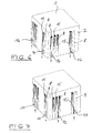
- FIG. 4 shows an embodiment of an artificial stone 1, arranged on the side surfaces 2 composite sections 8 and 15 are that with composite sections of neighboring stones work together to form a toothing.
- the Composite sections 8 and 15 are semi-cylindrical educated.
- the artificial stone 1 has a circumferential spacer 7, in the form of a horizontal ridge on the bottom edge the side surfaces 2 is arranged.
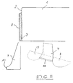
- Figure 5 shows the top of the artificial stone of the figure 4 in vertical section. You can clearly see the spacer 7 in the form of a horizontal ridge, the arranged in the region of the lower edge of the side surface 2 is. The ridge has a narrow contact surface 10 and runs diagonally upwards.
- the two lower views are details of the spacer shown.
- the right view clearly shows that the spacer 7 between two semi-cylindrical Composite sections 8 is arranged.
- the left view shows the spacer in an enlarged section.
- Figure 6 shows a further embodiment of an artificial stone 1, which is also on its side surfaces 2 with composite sections 8 and 15 is provided as in the embodiment of Figure 4.
- spacers 16 in the shape of vertical ridges on the bottom of the semi-cylindrical sections of the composite sections 15 arranged. These spacers 16 act with the Side surfaces of the neighboring stones together (laying phase), are destroyed when shaken when laid.
- Figure 7 shows an embodiment in which spacers 11 also in the form of vertical ridges with front Contact surfaces 12 are formed. These spacers 11 are here, however, between the adjacent composite sections 8 and 15 arranged and each act with a Composite section of the laid neighboring bricks together. The Effect is the same as in the other embodiments.
Landscapes
- Engineering & Computer Science (AREA)
- Architecture (AREA)
- Civil Engineering (AREA)
- Structural Engineering (AREA)
- Road Paving Structures (AREA)
- Materials For Medical Uses (AREA)
- Curing Cements, Concrete, And Artificial Stone (AREA)
- Prostheses (AREA)
Abstract
Description
Die vorliegende Erfindung betrifft einen Kunststein für Pflasterzwecke mit senkrecht oder schräg zur Verlegeebene gerichteten Seitenflächen, an denen Abstandshalter angeordnet sind.The present invention relates to an artificial stone for Paving purposes with perpendicular or oblique to the installation level directed side surfaces on which spacers are arranged are.
Derartige Abstandshalter dienten aus Sicht der Hersteller ursprünglich dem Zweck, Steinkanten ohne Fase beim Transport gegen Abplatzungen zu schützen. Diese Abstandshalter hatten daher eine geringere Tiefe als die Soll-Fugenbreite.Such spacers were used from the manufacturer's point of view originally the purpose of stone edges without chamfer during transport to protect against flaking. These spacers therefore had a shallower depth than the target joint width.
In der Praxis wurde aus derartigen Abstandshaltern jedoch eine willkommene Verlegehilfe. Dabei wurde mißbräuchlich der nur für den Transport bestimmte Abstandshalter zu einem Abstandshalter beim Verlegen. Aus Sicht des Pflasterverlegers sind die Abstandshalter Hilfsmittel geworden, die ohne zusätzlichen Arbeitsaufwand die Erreichung annähernd gleichmäßiger Fugenbreiten ermöglichen. Wenn man den Arbeitsaufwand bedenkt, den handwerklich einwandfreies Pflasterverlegen mit Soll-Fugenbreiten erfordert, kann man mit Sicherheit davon ausgehen, daß auch in Zukunft die Tiefe der Abstandshalter gleich Fugenbreite sein wird. Das hat jedoch zur Folge, daß zu geringe Fugenbreiten eingehalten werden und eine Verlegung Stein an Stein (benachbarte Steine stehen unmittelbar in Kontakt) erfolgt, wodurch das Pflastergefüge nicht mehr die notwendige Elastizität erhält, die nur über ordnungsgemäß verfüllte Fugen erreicht wird, wenn gleichzeitig der direkte Kontakt Stein an Stein vermieden wird.In practice, however, such spacers became a welcome laying aid. It became abusive the spacer only for transport to one Spacers when laying. From the pavement's point of view the spacers have become aids without additional workload to achieve the achievement enable uniform joint widths. If you look at the amount of work considering laying the perfect plaster with required joint widths, you can use Assume certainty that depth will continue in the future the spacer will be equal to the joint width. That has however, the result is that joint widths are too small and laying stone to stone (neighboring Stones are in direct contact), which means that Pavement structure no longer receives the necessary elasticity, that only reaches through properly filled joints becomes, if at the same time the direct contact stone to stone is avoided.
Gleiche Überlegungen treffen auf Kunststeine zu, die mit vorstehenden Verbundabschnitten an den Seitenflächen versehen sind, die mit vorstehenden Verbundabschnitten an den Seitenflächen eines benachbarten Steines zusammenwirken. Diese Verbundabschnitte besitzen beispielsweise die Form von Zähnen und hieran angepaßten Zahnlücken. Beim Aneinandersetzen von mehreren Steinen sorgen sie durch ihren Eingriff für einen festen Verband, wobei beim Aneinandersetzen der Steine hierzwischen eine Fuge ausgebildet wird. Eine derartige Fuge hat insbesondere den Sinn, eine Möglichkeit für die Versickerung von Regenwasser zu schaffen. Auch beim Verlegen von derartigen Steinen werden normalerweise die Verbundabschnitte von benachbarten Steinen eng aneinandergesetzt, so daß die Verbundabschnitte direkten Kontakt miteinander haben. Das hat zur Folge, daß zwischen den Verbundabschnitten keine Fuge mehr vorhanden ist, die für die notwendige Elastizität des Pflastergefüges sorgt.The same considerations apply to artificial stones that come with projecting composite sections on the side surfaces are with the above composite sections on the Side surfaces of an adjacent stone interact. These composite sections have the shape, for example of teeth and tooth gaps adapted to them. When sitting together they take care of several stones through their intervention for a firm bandage, while putting them together a joint is formed between the stones. A such a joint has the sense, in particular, of a possibility for rainwater infiltration. Also at Laying such stones will usually be the Composite sections of neighboring stones placed close together, so that the composite sections are in direct contact with each other to have. As a result, between the composite sections there is no longer a joint for the necessary elasticity of the plaster structure ensures.
Der Erfindung liegt die Aufgabe zugrunde, einen Kunststein der angegebenen Art zu schaffen, mit dem in der Gebrauchsphase (verlegter Zustand) bei Einhaltung des Soll-Fugenmaßes ein direkter Kontakt mit dem Nachbarstein verhindert werden kann.The invention has for its object an artificial stone to create the specified type with that in the use phase (installed condition) if the required joint dimension is observed prevents direct contact with the neighboring stone can be.
Diese Aufgabe wird erfindungsgemäß bei einem Kunststein der angegebenen Art dadurch gelöst, daß die Fläche des Abstandshalters zum Kontaktieren eines benachbarten Steines so klein ausgewählt ist, daß sie zwar beim Verlegen die Idealposition des Steines mit dem Soll-Fugenabstand sichert, jedoch beim Abrütteln des verlegten Pflasters zerstört wird.This object is achieved with an artificial stone specified type solved in that the surface of the spacer for contacting an adjacent stone is selected so small that it is the laying Ensures the ideal position of the stone with the target joint spacing but destroyed when shaking off the patch becomes.
Beim Verlegen wirkt somit der erfindungsgemäß ausgebildete Abstandshalter als "echter" Abstandshalter, der für eine Einhaltung des Soll-Fugenabstandes sorgt. Der Stein kann daher gezielt so verlegt werden, daß sein Abstandshalter gegen den benachbarten Stein stößt (gegen eine Seitenfläche, einen anderen Abstandshalter, einen Verbundabschnitt etc.). Damit stellt der Abstandshalter eine wesentliche Verlegehilfe dar, da der Arbeitsaufwand zum exakten Verlegen unter Einhaltung des Soll-Fugenabstandes verringert wird.When laying, the trained according to the invention thus acts Spacers as a "real" spacer that is suitable for a Adherence to the target joint spacing ensures. The stone can therefore be deliberately laid so that its spacer bumps against the neighboring stone (against a side surface, another spacer, a composite section Etc.). The spacer thus represents an essential one Laying aid because the workload for exact laying reduced while maintaining the target joint spacing becomes.
In der Gebrauchsphase, d.h. im verlegten Zustand des Steines, wird jedoch durch das Abrütteln des verlegten Pflasters die Kontaktfläche bzw. der Kontaktabschnitt des Abstandshalters zerstört (abgebrochen), so daß nach dem Abrütteln kein direkter Kontakt mehr zwischen dem Abstandshalter und dem benachbarten Stein vorhanden ist. Damit wird auch in diesem Bereich eine Fuge (wenn auch ggf. mit geringerer Breite) ausgebildet, die verfüllt wird, so daß das Pflastergefüge die gewünschte Elastizität erhält.In the use phase, i.e. when the stone is laid, however, by shaking off the pavement the contact surface or the contact section of the spacer destroyed (broken off) so that after shaking no more direct contact between the spacer and the neighboring stone is present. So that will a joint in this area as well (albeit with a smaller Width), which is filled so that the Pavement structure receives the desired elasticity.
Die Zerstörung der Kontaktfläche bzw. des Kontaktabschnittes des Abstandshalters beim Abrütteln des verlegten Pflasters wird erreicht, indem die Kontaktfläche bzw. der Kontaktabschnitt entsprechend klein ausgebildet wird. Exakte Größenangaben lassen sich hier nicht festlegen und hängen von den jeweiligen Gegebenheiten ab. Sie sind unter Umständen empirisch über Versuche zu ermitteln. Wichtig ist jedenfalls, daß bei üblichen Vibrationskräften und Vibrationszeiten, die beim Pflasterverlegen Anwendung finden, ein Reißen, Abbrechen, Lösen etc. des Kontaktabschnittes bzw. ein Zerstören der Kontaktfläche des Abstandshalters erreicht werden soll. The destruction of the contact surface or the contact section the spacer when shaking off the installed plaster is achieved by the contact surface or the contact section is made correspondingly small. Exact Sizes cannot be specified and hung here depending on the circumstances. You may be to be determined empirically via experiments. In any case, it is important that with usual vibration forces and vibration times, which are used for laying pavement Tearing, breaking off, loosening etc. of the contact section or destroys the contact surface of the spacer shall be.
Es ist augenscheinlich, daß hier nicht unbedingt die gesamte Kontaktfläche bzw. der gesamte Kontaktabschnitt zerstört werden muß. Selbst wenn noch Kontaktbrücken bestehen bleiben, ist der erfindungsgemäße Effekt erreicht, denn hierdurch wird die Elastizität des verlegten Pflasters nach ordnungsgemäßer Fugenverfüllung wesentlich gesteigert.It is evident that not all of them here Contact area or the entire contact section destroyed must become. Even if there are still contact bridges remain, the effect according to the invention is achieved, because in this way the elasticity of the pavement is reduced proper joint backfill significantly increased.
Bei dem erfindungsgemäß ausgebildeten Kunststein sorgt somit der Abstandshalter beim Verlegen für den Soll-Fugenabstand und verhindert beim Verlegen den direkten Kontakt Stein auf Stein, Stein auf Verbundabschnitt und Verbundabschnitt auf Verbundabschnitt, abgesehen von den direkten Kontaktflächen der Abstandshalter, die beim Abrütteln des Pflasters zerstört werden oder abbrechen. Der Abstandshalter wird daher in der Gebrauchsphase des Pflasters nicht mehr wirksam. Nach Zerstörung der Kontaktfläche der Abstandshalter wird der Abstand zwischen den Steinen durch das Fugenfüllmaterial gesichert.In the artificial stone designed according to the invention thus ensures the spacer when laying for the target joint spacing and prevents direct contact when laying Stone on stone, stone on composite section and composite section on composite section, apart from the direct Contact surfaces of the spacers that when shaking the Plasters may be destroyed or broken off. The spacer is therefore not in the use phase of the patch more effective. After destroying the contact surface of the spacers is the distance between the stones the joint filling material secured.
Wie erwähnt, muß die Kontaktfläche des Abstandshalters klein ausgebildet sein, um eine Zerstörung beim Abrütteln des verlegten Pflasters zu ermöglichen. Dies wird bei einer Ausführungsform erreicht, bei der der Abstandshalter eine annährend punktförmige Kontaktfläche besitzt. Eine weitere Ausführungsform zeichnet sich dadurch aus, daß der Abstandshalter eine annähernd lineare Kontaktfläche besitzt, beispielsweise in der Form eines Grates.As mentioned, the contact surface of the spacer be made small to destroy when shaken to allow the pavement to be laid. This will be the case with a Embodiment achieved in which the spacer has almost punctiform contact surface. Another Embodiment is characterized in that the spacer has an approximately linear contact area, for example in the form of a ridge.
Eine spezielle Ausführungsform der Erfindung zeichnet sich dadurch aus, daß der Abstandshalter in der Form einer Aufwölbung an der Seitenfläche ausgebildet ist. Die Aufwölbung ist zweckmäßigerweise pyramidenförmig, halb- oder viertelkugelig. Diese Ausgestaltungen sichern eine annährend punktförmige Kontaktfläche mit dem Nachbarstein. Eine konische Ausgestaltung ist ebenfalls möglich.A special embodiment of the invention stands out characterized in that the spacer in the form of a bulge is formed on the side surface. The bulge is expediently pyramidal, hemispherical or quarter-spherical. These configurations almost ensure you punctiform contact surface with the neighboring stone. A conical one Design is also possible.
Eine weitere Ausführungsform der Erfindung zeichnet sich dadurch aus, daß der Abstandshalter als horizontaler Grat an der Seitenfläche ausgebildet ist. Dieser Grat ist vorzugsweise an der Unterkante der Seitenfläche ausgebildet. Bei einer weiteren Ausführungsform ist der Abstandshalter als vertikaler Grat an der Seitenfläche ausgebildet. Diese Grate können an Seitenflächen von benachbarten Steinen stoßen. Eine besonders bevorzugte Lösung sieht jedoch vor, daß die horizontalen Grate an den Seitenwänden des Steines annähernd punktuell auf vertikale Ausformungen der Seitenwände angrenzender Steine stoßen, beispielsweise Verbundabschnitte dieser Steine. Wie erwähnt, wird hierdurch ein annähernd punktueller Kontakt sichergestellt. Bei einer anderen Lösung stoßen die vertikalen Grate an den Seitenwänden des Steines annähernd punktuell auf horizontale Ausformungen der Seitenwände angrenzender Steine. Auch hier wird ein annähernd punktueller Kontakt sichergestellt.Another embodiment of the invention stands out characterized in that the spacer as a horizontal ridge is formed on the side surface. This ridge is preferred formed on the lower edge of the side surface. In another embodiment, the spacer formed as a vertical ridge on the side surface. This Burrs can appear on the side surfaces of neighboring stones bump. However, a particularly preferred solution provides that the horizontal ridges on the side walls of the stone almost at certain points on vertical shapes of the side walls abutting adjacent stones, for example composite sections these stones. As mentioned, this makes an approximation selective contact ensured. Another one Solution encounter the vertical ridges on the side walls of the stone approximately at points on horizontal formations the side walls of adjacent stones. Here too is a almost point contact ensured.
Wenn der Kunststein mit mindestens einem vorstehenden Verbundabschnitt an der Seitenfläche versehen ist, der mit einem vorstehenden Verbundabschnitt eines benachbarten Steines zusammenwirkt, um eine Verzahnung herzustellen, ist bei einer weiteren Ausführungsform der Erfindung der Abstandshalter in dem Bereich der Seitenfläche angeordnet, mit dem der Verbundabschnitt des benachbarten Steines in Kontakt tritt. Mit anderen Worten, hierbei wird verhindert, daß ein Verbundabschnitt direkt gegen die Seitenfläche des Nachbarsteines stößt und somit einen unerwünschten Kontakt Stein an Stein bildet. Statt dessen stößt der Verbundabschnitt mit seiner Spitze gegen den Abstandshalter, der beispielsweise in der Form eines horizontalen Grates ausgebildet ist, so daß der gewünschte Fugenabstand sichergestellt wird. Der Abstandshalter ist dabei vorzugsweise benachbart zum Verbundabschnitt angeordnet, da in diesem Bereich die Seitenfläche vom Verbundabschnitt des Nachbarsteines kontaktiert wird.If the artificial stone with at least one projecting composite section is provided on the side surface with a projecting composite section of an adjacent one Stone interacts to produce a toothing in a further embodiment of the invention the spacer arranged in the area of the side surface, with which the composite section of the neighboring stone in Contact occurs. In other words, this prevents that a composite section directly against the side surface of the Neighboring stone encounters and thus an undesirable contact Stone to stone forms. Instead, the composite section bumps with its tip against the spacer, the for example in the form of a horizontal ridge is so that the desired joint spacing is ensured becomes. The spacer is preferably adjacent arranged to the composite section, because in this area the side surface of the composite section of the neighboring stone is contacted.
Sind auf einer Seitenfläche zwei benachbarte Verbundabschnitte angeordnet, beispielsweise in der Form von Zähnen, die zwischen sich eine Zahnlücke bilden, so ist der Abstandshalter zweckmäßigerweise zwischen den beiden benachbarten Verbundabschnitten, d.h. in der Zahnlücke, angeordnet, da in diesem Bereich ein Verbundabschnitt (Zahn) des Nachbarsteines eingreift. Diese Ausführungsform hat den besonderen Vorteil, daß der Abstandshalter so geschützt am Stein angeordnet ist, daß er während sämtlicher Transportphasen in seinen für die spätere Funktion wichtigen Teilen nicht zerstört wird.Are two adjacent composite sections on one side surface arranged, for example in the form of teeth, which form a tooth gap between them is the spacer expediently between the two neighboring ones Composite sections, i.e. in the tooth gap, arranged, because in this area a composite section (tooth) of the Intervening stone intervenes. This embodiment has the special one Advantage that the spacer is so protected on Stone is arranged so that it is during all transport phases in its parts important for its later function is not destroyed.
Noch eine andere Lösung der Erfindung betrifft ebenfalls einen Kunststein mit mindestens einem vorstehenden Verbundabschnitt an der Seitenfläche, der mit einem vorstehenden Verbundabschnitt eines benachbarten Steines zusammenwirkt. Hierbei ist erfindungsgemäß der Abstandshalter auf dem Vorderabschnitt des Verbundabschnittes angeordnet, beispielsweise in der Form eines vertikalen Grates. Diese Ausführungsform bringt jedoch insofern gewisse Probleme mit sich, als daß die Abstandshalter bereits beim Transport bzw. Abklammern der Steine leicht zerstört werden können.Yet another solution to the invention also relates an artificial stone with at least one projecting composite section on the side surface that with a protruding Composite section of an adjacent stone interacts. Here, the spacer is open according to the invention arranged the front portion of the composite portion, for example in the form of a vertical ridge. This embodiment however, brings with it certain problems itself as that the spacers already during transportation or stapling the stones can be easily destroyed.
Generell ist noch anzumerken, daß der Abstandshalter vorzugsweise nur im unteren Bereich der Seitenfläche angeordnet ist, um eine durchgehende Verfüllung mit Fugenmaterial im oberen Bereich der Seitenfläche zu ermöglichen. Auch die Verbundabschnitte, wenn solche vorgesehen sind, sind vorzugsweise nur im unteren Bereich der Seitenfläche angeordnet, um diesen Effekt zu ermöglichen. Bei einem Anblick von oben auf das verlegte Pflaster erhält der Betrachter daher den Eindruck einheitlicher durchlaufender Fugen.In general, it should also be noted that the spacer is preferred arranged only in the lower area of the side surface is to ensure continuous filling with jointing material to allow in the upper area of the side surface. Also the Composite sections, if any, are preferred arranged only in the lower area of the side surface, to enable this effect. At a sight of The viewer therefore gets on top of the pavement the impression of uniform, continuous joints.
Die Erfindung wird nachfolgend anhand von Ausführungsbeispielen in Verbindung mit der Zeichnung im einzelnen erläutert. Es zeigen:
Figur 1- einen Teil eines Kunststeines in räumlicher Ansicht, dessen eine Seitenfläche mit Abstandshaltern einer ersten Ausführungsform versehen ist;
Figur 2- eine Ansicht wie
Figur 1, die eine zweite Ausführungsform eines Abstandshalters zeigt; Figur 3- eine Ansicht wie
Figur 1, die eine dritte Ausführungsform eines Abstandshalters zeigt; Figur 4- eine räumliche Ansicht eines Kunststeines, dessen Seitenflächen mit Verbundabschnitten und einem Abstandshalter in der Form eines horizontalen Grates versehen sind;
Figur 5- einen Vertikalschnitt durch den
Kunststein der Figur 4 und zwei Detailansichten des Abstandshalters; - Figur 6
- eine räumliche Ansicht eines Kunststeines mit Verbundabschnitten auf den Seitenflächen, wobei bestimmte Verbundabschnitte mit Abstandshaltern in der Form eines vertikalen Grates versehen sind; und
Figur 7- eine Ansicht wie Figur 6, bei der Abstandshalter in der Form von vertikalen Graten zwischen benachbarten Verbundabschnitten angeordnet sind.
- Figure 1
- a part of an artificial stone in a spatial view, one side surface is provided with spacers of a first embodiment;
- Figure 2
- a view like Figure 1, showing a second embodiment of a spacer;
- Figure 3
- a view like Figure 1, showing a third embodiment of a spacer;
- Figure 4
- a three-dimensional view of an artificial stone, the side surfaces are provided with composite sections and a spacer in the form of a horizontal ridge;
- Figure 5
- a vertical section through the artificial stone of Figure 4 and two detailed views of the spacer;
- Figure 6
- a spatial view of an artificial stone with composite sections on the side surfaces, wherein certain composite sections are provided with spacers in the form of a vertical ridge; and
- Figure 7
- a view like Figure 6, in which spacers are arranged in the form of vertical ridges between adjacent composite sections.
Der in Figur 1 teilweise gezeigte Kunststein 1 besteht aus
Beton und hat die Form eines Quaders. Auf einer vertikalen
Seitenfläche 2 weist er Abstandshalter in der Form von Aufwölbungen
auf, von denen ein Abstandshalter 3 halbkugelförmig,
ein Abstandshalter 5 viertelkugelförmig und ein Abstandshalter
4 pyramidenförmig ausgebildet ist. Alle Abstandshalter
weisen in ihrem vorstehenden Endabschnitt eine
Kontaktfläche 6 auf, die annähernd die Form eines Punktes
besitzt.The
Die in Figur 1 gezeigten drei Ausführungsformen von Abstandshaltern sind natürlich nur beispielhaft gemeinsam auf einer Seitenfläche eines Kunststeines dargestellt. In Wirklichkeit hat der Stein nur Abstandshalter gemäß einer Ausführungsform, wobei ein oder mehrere Abstandshalter über eine oder mehrere Seitenflächen des Steines verteilt sein können.The three embodiments of spacers shown in Figure 1 are of course only exemplary together a side surface of an artificial stone. In reality the stone only has spacers according to one embodiment, taking one or more spacers over one or more side surfaces of the stone can be distributed can.
Bei dem hier dargestellten Kunststein handelt es sich um
einen Pflasterstein. Im verlegten Zustand soll der Pflasterstein
von einer Fuge umgeben sein, die ein bestimmtes
vorgegebenes Maß besitzen soll und nach dem Verlegen mit
Fugenfüllmaterial aufgefüllt wird. Die Abstandshalter sind
dabei genauso ausgebildet, daß ihre Höhe, d.h. der Abstand
der Kontaktfläche 6 von der Seitenfläche 2, exakt dem Soll-Fugenmaß
entspricht. Beim Verlegen dienen daher die Abstandshalter
als Verlegehilfe zur exakten Einhaltung des
Soll-Fugenmaßes.The artificial stone shown here is
a paving stone. When laid, the paving stone should
be surrounded by a fugue that a certain
should have the specified dimension and after laying with
Joint filling material is filled up. The spacers are
trained in such a way that their height, i.e. the distance
the contact surface 6 from the
Nach der Verlegung des Pflasters wird dieses abgerüttelt, damit die einzelnen Pflastersteine einen festen Sitz erhalten. Durch das Abrütteln werden die mit den Nachbarsteinen in Kontakt stehenden Kontaktflächen 6 bzw. Kontaktabschnitte der Abstandshalter abgebrochen bzw. zerstört, so daß kein direkter Kontakt von Stein zu Stein mehr gegeben ist. Es wird eine durchlaufende Fuge erzielt, und zwar auch im Bereich der Abstandshalter. Auf diese Weise kann die gewünschte Elastizität des Pflasters nach dem Auffüllen der Fugen mit Fugenfüllmaterial erreicht werden.After laying the patch, it is shaken off, so that the individual paving stones get a firm fit. By shaking them off, they become with the neighboring stones in contact contact areas 6 or contact sections the spacer is broken off or destroyed, see above that there was no more direct contact from stone to stone is. A continuous joint is achieved, and indeed in the area of the spacers. This way you can get the one you want Elasticity of the patch after filling the Joints can be achieved with joint filling material.
Figur 2 zeigt eine Ausführungsform, bei der ein Abstandshalter
7 in der Form eines horizontalen Grates auf einer
Seitenfläche eines Kunststeines ausgebildet ist. Diesr Grat
endet in einer schmalen Fläche 10, die für einen Kontakt
mit dem Nachbarstein vorgesehen ist. Bei dieser Ausführungsform
weist der Nachbarstein (gestrichelt dargestellt)
einen vorstehenden Verbundabschnitt 8 auf, der etwa die
Form eines halben Zylinders besitzt. Wenn die Fläche 10 mit
dem Verbundabschnitt 8 in Kontakt tritt, entsteht theoretisch
ein etwa linearer Kontaktabschnitt, der in der Praxis
jedoch ebenfalls als annähernd punktförmige Fläche 9 ausgebildet
ist.Figure 2 shows an embodiment in which a
Bei der Ausführungsform der Figur 3 ist der Abstandshalter
11 in der Form eines vertikalen Grates mit einer schmalen
für den Kontakt vorgesehenen Fläche 12 ausgebildet. Der
Nachbarstein weist hierbei eine von der Seitenfläche vorstehende
horizontale Ausformung 14 auf, die einem liegenden
Viertelzylinder entspricht. Auch hier ergibt sich in der
Praxis ein annähernd punktförmiger Kontaktabschnitt 13.In the embodiment of Figure 3 is the
Auch bei den Ausführungsformen der Figuren 2 und 3 wird
durch das Abrütteln des verlegten Pflasters der Kontaktabschnitt
9 bzw. 13 zerstört, so daß hiernach kein Kontakt
Stein an Stein mehr gegeben ist.Also in the embodiments of Figures 2 and 3
by shaking off the pavement the
Figur 4 zeigt eine Ausführungsform eines Kunststeines 1,
auf dessen Seitenflächen 2 Verbundabschnitte 8 und 15 angeordnet
sind, die mit Verbundabschnitten von Nachbarsteinen
zusammewirken, um eine Verzahnung auszubilden. Die
Verbundabschnitte 8 und 15 sind dabei halbzylindrisch
ausgebildet.FIG. 4 shows an embodiment of an
Der Kunststein 1 besitzt einen umlaufenden Abstandshalter
7, der in der Form eines horizontalen Grates an der Unterkante
der Seitenflächen 2 angeordnet ist. Bei dieser Ausführungsform
treten Verbundabschnitte der Nachbarsteine
beim Verlegen mit dem Abstandshalter 7 in Kontakt, um das
exakte Fugenmaß festzulegen. Durch das Abrütteln des verlegten
Pflasters werden die entsprechenden Kontaktabschnitte
bzw. Kontaktflächen zerstört, so daß danach kein
Kontakt Stein an Stein mehr vorhanden ist.The
Figur 5 zeigt in der oberen Ansicht den Kunststein der Figur
4 im Vertikalschnitt. Man erkennt deutlich den Abstandshalter
7 in der Form eines horizontalen Grates, der
im Bereich der Unterkante der Seitenfläche 2 angeordnet
ist. Der Grat hat eine schmale Kontakfläche 10 und läuft
schräg nach oben aus.Figure 5 shows the top of the artificial stone of the figure
4 in vertical section. You can clearly see the
In den beiden unteren Ansichten sind Details des Abstandshalters
dargestellt. Die rechte Ansicht zeigt deutlich, daß
der Abstandshalter 7 zwischen zwei halbzylindrisch ausgebildeten
Verbundabschnitten 8 angeordnet ist. Die linke Ansicht
zeigt den Abstandshalter im vergrößerten Schnitt.In the two lower views are details of the spacer
shown. The right view clearly shows that
the
Figur 6 zeigt eine weitere Ausführungsform eines Kunststeines
1, der ebenfalls auf seinen Seitenflächen 2 mit Verbundabschnitten
8 und 15 versehen ist wie bei der Ausführungsform
der Figur 4. Hierbei sind Abstandshalter 16 in
der Form von vertikalen Graten auf dem unteren Bereich der
halbzylindrischen Abschnitte der Verbundabschnitte 15 angeordnet.
Diese Abstandshalter 16 wirken mit den
Seitenflächen der Nachbarsteine zusammen (Verlegephase),
werden jedoch im verlegten Zustand beim Abrütteln zerstört.Figure 6 shows a further embodiment of an
Figur 7 zeigt eine Ausführungsform, bei der Abstandshalter
11 ebenfalls in der Form von vertikalen Graten mit vorderen
Kontaktflächen 12 ausgebildet sind. Diese Abstandshalter 11
sind hierbei jedoch zwischen den benachbarten Verbundabschnitten
8 und 15 angeordnet und wirken jeweils mit einem
Verbundabschnitt der verlegten Nachbarsteine zusammen. Der
Effekt ist der gleiche wie bei den anderen Ausführungsformen.Figure 7 shows an embodiment in which spacers
11 also in the form of vertical ridges with front
Contact surfaces 12 are formed. These
Claims (13)
Priority Applications (3)
| Application Number | Priority Date | Filing Date | Title |
|---|---|---|---|
| DE59904443T DE59904443D1 (en) | 1999-03-15 | 1999-03-15 | Artificial stone for paving |
| EP99105296A EP1036882B1 (en) | 1999-03-15 | 1999-03-15 | Artificial stone for pavings |
| AT99105296T ATE233847T1 (en) | 1999-03-15 | 1999-03-15 | ARTIFICIAL STONE FOR PAVING PURPOSES |
Applications Claiming Priority (1)
| Application Number | Priority Date | Filing Date | Title |
|---|---|---|---|
| EP99105296A EP1036882B1 (en) | 1999-03-15 | 1999-03-15 | Artificial stone for pavings |
Publications (2)
| Publication Number | Publication Date |
|---|---|
| EP1036882A1 true EP1036882A1 (en) | 2000-09-20 |
| EP1036882B1 EP1036882B1 (en) | 2003-03-05 |
Family
ID=8237782
Family Applications (1)
| Application Number | Title | Priority Date | Filing Date |
|---|---|---|---|
| EP99105296A Expired - Lifetime EP1036882B1 (en) | 1999-03-15 | 1999-03-15 | Artificial stone for pavings |
Country Status (3)
| Country | Link |
|---|---|
| EP (1) | EP1036882B1 (en) |
| AT (1) | ATE233847T1 (en) |
| DE (1) | DE59904443D1 (en) |
Cited By (14)
| Publication number | Priority date | Publication date | Assignee | Title |
|---|---|---|---|---|
| FR2841915A1 (en) * | 2002-07-08 | 2004-01-09 | Bock Heinrich Et Cie Ets | Interlocking concrete block paving element e.g. for road, has distancing parts formed around edge of block, with each distancing parts having semicylindrical spacing elements |
| EP1335069A3 (en) * | 2002-02-07 | 2004-03-31 | Kombilith GmbH Entwicklung und Verwertung | Artificial stone for pavings |
| DE102006006019B3 (en) * | 2006-02-08 | 2007-06-28 | Beton Poetsch Gmbh & Co. Kg | Concrete paving slab comprises interlocking sections touching a side surface of a neighboring slab only with a contact line running parallel to a contact surface |
| DE102006051938A1 (en) * | 2006-11-01 | 2008-05-08 | Sf-Kooperation Gmbh Beton-Konzepte | Soil cover made of shaped bricks |
| DE102007012538A1 (en) * | 2007-03-13 | 2008-09-18 | Sf-Kooperation Gmbh Beton-Konzepte | Ground covering, is made of shaped bricks e.g. paving stones or slabs, where spacers are formed in side surface of bricks and contact cam is formed at side surface for durable contact transferring with adjacent shaped bricks |
| DE102009017511A1 (en) | 2009-04-15 | 2010-10-21 | Roth, Reiner, Dipl.-Ing. (Fh) | Concrete paving stone comprises circulating teeth or groups of teeth on stone sides that cog with teeth of adjacent concrete paving stone, where tooth tapers upward starting from foot side |
| US7850394B2 (en) | 2004-08-02 | 2010-12-14 | Schroeder Harald | Paving stone |
| DE102007015831B4 (en) * | 2006-04-01 | 2011-02-03 | Roth, Reiner, Dipl.-Ing. (Fh) | Concrete paving stone |
| EP2527533A1 (en) | 2011-05-23 | 2012-11-28 | Etablissements Heinrich Bock et Cie S.P.A.S. | Interlocking concrete paving block |
| US8616803B2 (en) | 2009-05-19 | 2013-12-31 | Baustoffwerke Gebhart & Soehne GmbH and Co. KG | Paving stone having stone flanks oriented preferably perpendicular to the laying plane |
| FR3010095A1 (en) * | 2013-09-05 | 2015-03-06 | Bock Heinrich Et Cie Ets | PERFECTLY PERFECTIONED CONCRETE PAVE |
| EP2966223A1 (en) * | 2014-07-12 | 2016-01-13 | Detlef Schröder | Interlocking paving block and paving laid with same |
| DE102017118906A1 (en) * | 2017-08-18 | 2019-02-21 | Wolfgang Schwarz | Corner set and arrangement with such |
| WO2020025073A1 (en) | 2018-08-01 | 2020-02-06 | Schroeder Detlef | Paving stone and paving produced using same |
Families Citing this family (6)
| Publication number | Priority date | Publication date | Assignee | Title |
|---|---|---|---|---|
| DE202009005515U1 (en) | 2009-04-15 | 2009-06-18 | Roth, Reiner, Dipl.-Ing. (Fh) | Concrete paving stone |
| DE102010007798B4 (en) | 2010-02-12 | 2014-11-27 | Reiner Roth | Concrete paving stone |
| DE202010002217U1 (en) | 2010-02-12 | 2010-04-22 | Roth, Reiner, Dipl.-Ing. (Fh) | Concrete paving stone |
| DE102021000131A1 (en) | 2021-01-14 | 2022-07-14 | Reiner Roth | concrete paver |
| DE202022000899U1 (en) | 2022-04-11 | 2022-05-03 | Reiner Roth | concrete paver |
| DE102022001230A1 (en) | 2022-04-11 | 2023-10-12 | Reiner Roth | Concrete paving stone |
Citations (4)
| Publication number | Priority date | Publication date | Assignee | Title |
|---|---|---|---|---|
| DE2452475A1 (en) * | 1972-12-05 | 1976-05-06 | Jordan Reinhard | Highway paving slab module - interlocking briquettes connection ruptured during compaction etc. |
| DE4446427A1 (en) * | 1994-02-16 | 1995-08-17 | Zapf Werner Kg | Concrete flagstone with main body as useful face |
| US5466089A (en) * | 1995-01-03 | 1995-11-14 | Jurik; Dean | Ground and floor covering block |
| DE29721360U1 (en) * | 1997-12-03 | 1998-02-12 | Staats Manfred | Molded stone with spacers |
-
1999
- 1999-03-15 DE DE59904443T patent/DE59904443D1/en not_active Expired - Lifetime
- 1999-03-15 EP EP99105296A patent/EP1036882B1/en not_active Expired - Lifetime
- 1999-03-15 AT AT99105296T patent/ATE233847T1/en active
Patent Citations (4)
| Publication number | Priority date | Publication date | Assignee | Title |
|---|---|---|---|---|
| DE2452475A1 (en) * | 1972-12-05 | 1976-05-06 | Jordan Reinhard | Highway paving slab module - interlocking briquettes connection ruptured during compaction etc. |
| DE4446427A1 (en) * | 1994-02-16 | 1995-08-17 | Zapf Werner Kg | Concrete flagstone with main body as useful face |
| US5466089A (en) * | 1995-01-03 | 1995-11-14 | Jurik; Dean | Ground and floor covering block |
| DE29721360U1 (en) * | 1997-12-03 | 1998-02-12 | Staats Manfred | Molded stone with spacers |
Cited By (17)
| Publication number | Priority date | Publication date | Assignee | Title |
|---|---|---|---|---|
| EP1335069A3 (en) * | 2002-02-07 | 2004-03-31 | Kombilith GmbH Entwicklung und Verwertung | Artificial stone for pavings |
| EP1380689A1 (en) * | 2002-07-08 | 2004-01-14 | Etablissements Heinrich Bock et Cie (S.A.S.) | Interlocking concrete paving element |
| FR2841915A1 (en) * | 2002-07-08 | 2004-01-09 | Bock Heinrich Et Cie Ets | Interlocking concrete block paving element e.g. for road, has distancing parts formed around edge of block, with each distancing parts having semicylindrical spacing elements |
| US7850394B2 (en) | 2004-08-02 | 2010-12-14 | Schroeder Harald | Paving stone |
| DE102006006019B3 (en) * | 2006-02-08 | 2007-06-28 | Beton Poetsch Gmbh & Co. Kg | Concrete paving slab comprises interlocking sections touching a side surface of a neighboring slab only with a contact line running parallel to a contact surface |
| DE102007015831B4 (en) * | 2006-04-01 | 2011-02-03 | Roth, Reiner, Dipl.-Ing. (Fh) | Concrete paving stone |
| DE102006051938A1 (en) * | 2006-11-01 | 2008-05-08 | Sf-Kooperation Gmbh Beton-Konzepte | Soil cover made of shaped bricks |
| DE102007012538A1 (en) * | 2007-03-13 | 2008-09-18 | Sf-Kooperation Gmbh Beton-Konzepte | Ground covering, is made of shaped bricks e.g. paving stones or slabs, where spacers are formed in side surface of bricks and contact cam is formed at side surface for durable contact transferring with adjacent shaped bricks |
| DE102009017511A1 (en) | 2009-04-15 | 2010-10-21 | Roth, Reiner, Dipl.-Ing. (Fh) | Concrete paving stone comprises circulating teeth or groups of teeth on stone sides that cog with teeth of adjacent concrete paving stone, where tooth tapers upward starting from foot side |
| US8616803B2 (en) | 2009-05-19 | 2013-12-31 | Baustoffwerke Gebhart & Soehne GmbH and Co. KG | Paving stone having stone flanks oriented preferably perpendicular to the laying plane |
| EP2527533A1 (en) | 2011-05-23 | 2012-11-28 | Etablissements Heinrich Bock et Cie S.P.A.S. | Interlocking concrete paving block |
| FR3010095A1 (en) * | 2013-09-05 | 2015-03-06 | Bock Heinrich Et Cie Ets | PERFECTLY PERFECTIONED CONCRETE PAVE |
| EP2851469A1 (en) | 2013-09-05 | 2015-03-25 | Etablissements Heinrich Bock et Cie S.P.A.S. | Improved self-locking concrete tile |
| EP2966223A1 (en) * | 2014-07-12 | 2016-01-13 | Detlef Schröder | Interlocking paving block and paving laid with same |
| DE102017118906A1 (en) * | 2017-08-18 | 2019-02-21 | Wolfgang Schwarz | Corner set and arrangement with such |
| WO2020025073A1 (en) | 2018-08-01 | 2020-02-06 | Schroeder Detlef | Paving stone and paving produced using same |
| US11384487B2 (en) | 2018-08-01 | 2022-07-12 | Detlef SCHROEDER | Paver and pavement made therefrom |
Also Published As
| Publication number | Publication date |
|---|---|
| ATE233847T1 (en) | 2003-03-15 |
| EP1036882B1 (en) | 2003-03-05 |
| DE59904443D1 (en) | 2003-04-10 |
Similar Documents
| Publication | Publication Date | Title |
|---|---|---|
| EP1036882B1 (en) | Artificial stone for pavings | |
| EP0377460B1 (en) | Set of concrete paving blocks | |
| WO1997031155A1 (en) | Artificial stone for stabilising traffic areas in the open | |
| DE4405616A1 (en) | Paving stone with lateral spacers | |
| EP0063795A1 (en) | Paving element, paving unit of diverse paving elements and group of paving elements | |
| EP1335069B1 (en) | Artificial stone for pavings | |
| DE19520887C2 (en) | Paving stone laying element | |
| EP0259735A1 (en) | Ground covering by (concrete) blocks | |
| EP3830339B1 (en) | Paving stone and paving produced using same | |
| EP1024226B1 (en) | Artificial stone for pavings | |
| EP1088941B1 (en) | Gutter and gutter element therefor | |
| DE3116540C2 (en) | Floor covering element, laying unit formed from several floor covering elements and association of floor covering elements | |
| DE3303210A1 (en) | Laying unit | |
| DE3804760A1 (en) | Grass paving stone | |
| AT403389B (en) | PAVING STONE IN RECTANGULAR SHAPE | |
| DE3737620A1 (en) | Grass paving stones | |
| DE2225027A1 (en) | MOLDED CONCRETE BLOCK WITH SEVERAL VERTICAL OPENINGS AND POLYGONAL LIMITATION FOR SURFACE FASTENING OF TERRAIN | |
| EP1050624B1 (en) | Circular paving and wedge shaped stone therefor | |
| EP1057935B1 (en) | Paving stone | |
| EP0212036A1 (en) | Interconnecting stone for lawn | |
| DE10205135A1 (en) | Cobblestone has offset sections, with a simulated joint, fitted with projecting side ribs to mate with neighboring cobblestones without direct contact and maintain a nominal joint width | |
| EP3851581B1 (en) | Paving element made of concrete, surface covering and method for manufacturing a paving stone | |
| DE2251621C2 (en) | Composite covering with laying units and method for producing the composite covering | |
| EP0927792B1 (en) | Paving element | |
| DE19537823A1 (en) | Paving stone connection |
Legal Events
| Date | Code | Title | Description |
|---|---|---|---|
| PUAI | Public reference made under article 153(3) epc to a published international application that has entered the european phase |
Free format text: ORIGINAL CODE: 0009012 |
|
| 17P | Request for examination filed |
Effective date: 19991104 |
|
| AK | Designated contracting states |
Kind code of ref document: A1 Designated state(s): AT BE CH CY LI |
|
| AX | Request for extension of the european patent |
Free format text: AL;LT;LV;MK;RO;SI |
|
| AKX | Designation fees paid |
Free format text: AT BE CH CY LI |
|
| RBV | Designated contracting states (corrected) |
Designated state(s): AT BE DE NL |
|
| REG | Reference to a national code |
Ref country code: DE Ref legal event code: 8566 |
|
| RAP1 | Party data changed (applicant data changed or rights of an application transferred) |
Owner name: KOMBILITH GMBH ENTWICKLUNG UND VERWERTUNG |
|
| 17Q | First examination report despatched |
Effective date: 20020117 |
|
| GRAH | Despatch of communication of intention to grant a patent |
Free format text: ORIGINAL CODE: EPIDOS IGRA |
|
| GRAH | Despatch of communication of intention to grant a patent |
Free format text: ORIGINAL CODE: EPIDOS IGRA |
|
| GRAA | (expected) grant |
Free format text: ORIGINAL CODE: 0009210 |
|
| AK | Designated contracting states |
Designated state(s): AT BE DE NL |
|
| PG25 | Lapsed in a contracting state [announced via postgrant information from national office to epo] |
Ref country code: NL Free format text: LAPSE BECAUSE OF FAILURE TO SUBMIT A TRANSLATION OF THE DESCRIPTION OR TO PAY THE FEE WITHIN THE PRESCRIBED TIME-LIMIT Effective date: 20030305 |
|
| PG25 | Lapsed in a contracting state [announced via postgrant information from national office to epo] |
Ref country code: BE Free format text: LAPSE BECAUSE OF NON-PAYMENT OF DUE FEES Effective date: 20030331 |
|
| REF | Corresponds to: |
Ref document number: 59904443 Country of ref document: DE Date of ref document: 20030410 Kind code of ref document: P |
|
| NLV1 | Nl: lapsed or annulled due to failure to fulfill the requirements of art. 29p and 29m of the patents act | ||
| BERE | Be: lapsed |
Owner name: *KOMBILITH G.M.B.H. ENTWICKLUNG UND VERWERTUNG Effective date: 20030331 |
|
| PLBE | No opposition filed within time limit |
Free format text: ORIGINAL CODE: 0009261 |
|
| STAA | Information on the status of an ep patent application or granted ep patent |
Free format text: STATUS: NO OPPOSITION FILED WITHIN TIME LIMIT |
|
| 26N | No opposition filed |
Effective date: 20031208 |
|
| REG | Reference to a national code |
Ref country code: DE Ref legal event code: R082 Ref document number: 59904443 Country of ref document: DE Representative=s name: HAUCK PATENTANWALTSPARTNERSCHAFT MBB, DE |
|
| REG | Reference to a national code |
Ref country code: AT Ref legal event code: PC Ref document number: 233847 Country of ref document: AT Kind code of ref document: T Owner name: SEMMELROCK INTERNATIONAL GMBH, AT Effective date: 20180326 |
|
| PGFP | Annual fee paid to national office [announced via postgrant information from national office to epo] |
Ref country code: AT Payment date: 20180305 Year of fee payment: 20 |
|
| PGFP | Annual fee paid to national office [announced via postgrant information from national office to epo] |
Ref country code: DE Payment date: 20180426 Year of fee payment: 20 |
|
| REG | Reference to a national code |
Ref country code: DE Ref legal event code: R071 Ref document number: 59904443 Country of ref document: DE |
|
| REG | Reference to a national code |
Ref country code: AT Ref legal event code: MK07 Ref document number: 233847 Country of ref document: AT Kind code of ref document: T Effective date: 20190315 |