EP2849678B1 - Catheter delivery system for introducing an expandable heart valve prosthesis and medical device for the treatment of a heart valve defect - Google Patents
Catheter delivery system for introducing an expandable heart valve prosthesis and medical device for the treatment of a heart valve defect Download PDFInfo
- Publication number
- EP2849678B1 EP2849678B1 EP13714940.7A EP13714940A EP2849678B1 EP 2849678 B1 EP2849678 B1 EP 2849678B1 EP 13714940 A EP13714940 A EP 13714940A EP 2849678 B1 EP2849678 B1 EP 2849678B1
- Authority
- EP
- European Patent Office
- Prior art keywords
- operating handle
- catheter
- heart valve
- stent
- catheter tip
- Prior art date
- Legal status (The legal status is an assumption and is not a legal conclusion. Google has not performed a legal analysis and makes no representation as to the accuracy of the status listed.)
- Active
Links
- 210000003709 heart valve Anatomy 0.000 title claims description 331
- 230000007547 defect Effects 0.000 title claims description 13
- 230000007246 mechanism Effects 0.000 claims description 210
- 230000033001 locomotion Effects 0.000 claims description 62
- 230000000903 blocking effect Effects 0.000 claims description 10
- 206010061996 Heart valve stenosis Diseases 0.000 claims description 7
- 238000003825 pressing Methods 0.000 claims description 6
- 210000002216 heart Anatomy 0.000 description 49
- 238000002513 implantation Methods 0.000 description 49
- 238000003780 insertion Methods 0.000 description 39
- 230000037431 insertion Effects 0.000 description 39
- 238000006073 displacement reaction Methods 0.000 description 34
- 238000000034 method Methods 0.000 description 33
- 210000005240 left ventricle Anatomy 0.000 description 20
- 210000000709 aorta Anatomy 0.000 description 18
- 210000001765 aortic valve Anatomy 0.000 description 16
- 238000013459 approach Methods 0.000 description 16
- 239000000463 material Substances 0.000 description 13
- 239000008280 blood Substances 0.000 description 12
- 210000004369 blood Anatomy 0.000 description 12
- 210000002837 heart atrium Anatomy 0.000 description 11
- 206010002906 aortic stenosis Diseases 0.000 description 8
- 210000001367 artery Anatomy 0.000 description 8
- 230000017531 blood circulation Effects 0.000 description 8
- 210000004115 mitral valve Anatomy 0.000 description 8
- 230000002861 ventricular Effects 0.000 description 8
- 208000003017 Aortic Valve Stenosis Diseases 0.000 description 7
- 201000002064 aortic valve insufficiency Diseases 0.000 description 6
- 210000003128 head Anatomy 0.000 description 6
- 230000007704 transition Effects 0.000 description 6
- 238000010586 diagram Methods 0.000 description 5
- 210000005246 left atrium Anatomy 0.000 description 5
- 210000003102 pulmonary valve Anatomy 0.000 description 5
- 210000005241 right ventricle Anatomy 0.000 description 5
- 238000001356 surgical procedure Methods 0.000 description 5
- 238000012546 transfer Methods 0.000 description 5
- 206010002915 Aortic valve incompetence Diseases 0.000 description 4
- 210000002376 aorta thoracic Anatomy 0.000 description 4
- 210000003205 muscle Anatomy 0.000 description 4
- 210000004165 myocardium Anatomy 0.000 description 4
- 239000004033 plastic Substances 0.000 description 4
- 229920003023 plastic Polymers 0.000 description 4
- 210000001147 pulmonary artery Anatomy 0.000 description 4
- 210000000591 tricuspid valve Anatomy 0.000 description 4
- 206010067660 Heart valve incompetence Diseases 0.000 description 3
- QVGXLLKOCUKJST-UHFFFAOYSA-N atomic oxygen Chemical compound [O] QVGXLLKOCUKJST-UHFFFAOYSA-N 0.000 description 3
- 230000008602 contraction Effects 0.000 description 3
- 238000011161 development Methods 0.000 description 3
- 230000018109 developmental process Effects 0.000 description 3
- 230000004064 dysfunction Effects 0.000 description 3
- 238000005516 engineering process Methods 0.000 description 3
- 208000005907 mitral valve insufficiency Diseases 0.000 description 3
- HLXZNVUGXRDIFK-UHFFFAOYSA-N nickel titanium Chemical compound [Ti].[Ti].[Ti].[Ti].[Ti].[Ti].[Ti].[Ti].[Ti].[Ti].[Ti].[Ni].[Ni].[Ni].[Ni].[Ni].[Ni].[Ni].[Ni].[Ni].[Ni].[Ni].[Ni].[Ni].[Ni] HLXZNVUGXRDIFK-UHFFFAOYSA-N 0.000 description 3
- 229910001000 nickel titanium Inorganic materials 0.000 description 3
- 229910052760 oxygen Inorganic materials 0.000 description 3
- 239000001301 oxygen Substances 0.000 description 3
- 230000002685 pulmonary effect Effects 0.000 description 3
- 239000010935 stainless steel Substances 0.000 description 3
- 229910001220 stainless steel Inorganic materials 0.000 description 3
- 230000035488 systolic blood pressure Effects 0.000 description 3
- 230000001131 transforming effect Effects 0.000 description 3
- 206010002383 Angina Pectoris Diseases 0.000 description 2
- 206010020880 Hypertrophy Diseases 0.000 description 2
- 206010027727 Mitral valve incompetence Diseases 0.000 description 2
- 208000031481 Pathologic Constriction Diseases 0.000 description 2
- 208000018262 Peripheral vascular disease Diseases 0.000 description 2
- 229920002614 Polyether block amide Polymers 0.000 description 2
- 206010067171 Regurgitation Diseases 0.000 description 2
- 230000009471 action Effects 0.000 description 2
- 238000004873 anchoring Methods 0.000 description 2
- 238000010009 beating Methods 0.000 description 2
- 230000036770 blood supply Effects 0.000 description 2
- 230000000747 cardiac effect Effects 0.000 description 2
- 230000006835 compression Effects 0.000 description 2
- 238000007906 compression Methods 0.000 description 2
- 208000016569 congenital mitral valve insufficiency Diseases 0.000 description 2
- 230000003205 diastolic effect Effects 0.000 description 2
- 208000037265 diseases, disorders, signs and symptoms Diseases 0.000 description 2
- 208000035475 disorder Diseases 0.000 description 2
- 239000003814 drug Substances 0.000 description 2
- 210000004013 groin Anatomy 0.000 description 2
- 208000028867 ischemia Diseases 0.000 description 2
- 238000002355 open surgical procedure Methods 0.000 description 2
- 230000008569 process Effects 0.000 description 2
- 230000004088 pulmonary circulation Effects 0.000 description 2
- 210000003492 pulmonary vein Anatomy 0.000 description 2
- 210000005245 right atrium Anatomy 0.000 description 2
- 238000000926 separation method Methods 0.000 description 2
- 208000037804 stenosis Diseases 0.000 description 2
- 230000036262 stenosis Effects 0.000 description 2
- 230000002966 stenotic effect Effects 0.000 description 2
- 230000002792 vascular Effects 0.000 description 2
- 210000002620 vena cava superior Anatomy 0.000 description 2
- 101800004637 Communis Proteins 0.000 description 1
- 206010010356 Congenital anomaly Diseases 0.000 description 1
- 206010016803 Fluid overload Diseases 0.000 description 1
- 206010020772 Hypertension Diseases 0.000 description 1
- 208000007177 Left Ventricular Hypertrophy Diseases 0.000 description 1
- 241001465754 Metazoa Species 0.000 description 1
- 239000004677 Nylon Substances 0.000 description 1
- 208000002193 Pain Diseases 0.000 description 1
- 239000004696 Poly ether ether ketone Substances 0.000 description 1
- 239000004642 Polyimide Substances 0.000 description 1
- 206010037423 Pulmonary oedema Diseases 0.000 description 1
- 229910000831 Steel Inorganic materials 0.000 description 1
- 208000001122 Superior Vena Cava Syndrome Diseases 0.000 description 1
- 208000027418 Wounds and injury Diseases 0.000 description 1
- 230000001154 acute effect Effects 0.000 description 1
- 238000004458 analytical method Methods 0.000 description 1
- 210000003157 atrial septum Anatomy 0.000 description 1
- 238000005452 bending Methods 0.000 description 1
- JUPQTSLXMOCDHR-UHFFFAOYSA-N benzene-1,4-diol;bis(4-fluorophenyl)methanone Chemical compound OC1=CC=C(O)C=C1.C1=CC(F)=CC=C1C(=O)C1=CC=C(F)C=C1 JUPQTSLXMOCDHR-UHFFFAOYSA-N 0.000 description 1
- 238000007675 cardiac surgery Methods 0.000 description 1
- 230000002612 cardiopulmonary effect Effects 0.000 description 1
- 230000000295 complement effect Effects 0.000 description 1
- 230000001143 conditioned effect Effects 0.000 description 1
- 238000010276 construction Methods 0.000 description 1
- 230000003247 decreasing effect Effects 0.000 description 1
- 230000002950 deficient Effects 0.000 description 1
- 230000001419 dependent effect Effects 0.000 description 1
- 230000000694 effects Effects 0.000 description 1
- 210000000887 face Anatomy 0.000 description 1
- 210000001105 femoral artery Anatomy 0.000 description 1
- 208000025339 heart septal defect Diseases 0.000 description 1
- 208000018578 heart valve disease Diseases 0.000 description 1
- 238000003384 imaging method Methods 0.000 description 1
- 239000007943 implant Substances 0.000 description 1
- 208000014674 injury Diseases 0.000 description 1
- 230000003993 interaction Effects 0.000 description 1
- 238000013152 interventional procedure Methods 0.000 description 1
- 230000000302 ischemic effect Effects 0.000 description 1
- 210000003041 ligament Anatomy 0.000 description 1
- 238000002690 local anesthesia Methods 0.000 description 1
- 238000004519 manufacturing process Methods 0.000 description 1
- 230000003340 mental effect Effects 0.000 description 1
- 238000002324 minimally invasive surgery Methods 0.000 description 1
- 230000003387 muscular Effects 0.000 description 1
- 229920001778 nylon Polymers 0.000 description 1
- 210000000056 organ Anatomy 0.000 description 1
- 230000036407 pain Effects 0.000 description 1
- 210000003516 pericardium Anatomy 0.000 description 1
- 229920002530 polyetherether ketone Polymers 0.000 description 1
- 229920000139 polyethylene terephthalate Polymers 0.000 description 1
- 239000005020 polyethylene terephthalate Substances 0.000 description 1
- 229920001721 polyimide Polymers 0.000 description 1
- 229920001296 polysiloxane Polymers 0.000 description 1
- 229920002635 polyurethane Polymers 0.000 description 1
- 239000004814 polyurethane Substances 0.000 description 1
- 239000004800 polyvinyl chloride Substances 0.000 description 1
- 238000011084 recovery Methods 0.000 description 1
- 230000008439 repair process Effects 0.000 description 1
- 238000007789 sealing Methods 0.000 description 1
- 239000007787 solid Substances 0.000 description 1
- 230000007480 spreading Effects 0.000 description 1
- 238000003892 spreading Methods 0.000 description 1
- 239000010959 steel Substances 0.000 description 1
- 230000001839 systemic circulation Effects 0.000 description 1
- 238000012360 testing method Methods 0.000 description 1
- 230000001225 therapeutic effect Effects 0.000 description 1
- 210000001519 tissue Anatomy 0.000 description 1
- 230000008733 trauma Effects 0.000 description 1
- 238000002604 ultrasonography Methods 0.000 description 1
- 210000001631 vena cava inferior Anatomy 0.000 description 1
- 210000000596 ventricular septum Anatomy 0.000 description 1
Images


Classifications
-
- A—HUMAN NECESSITIES
- A61—MEDICAL OR VETERINARY SCIENCE; HYGIENE
- A61M—DEVICES FOR INTRODUCING MEDIA INTO, OR ONTO, THE BODY; DEVICES FOR TRANSDUCING BODY MEDIA OR FOR TAKING MEDIA FROM THE BODY; DEVICES FOR PRODUCING OR ENDING SLEEP OR STUPOR
- A61M25/00—Catheters; Hollow probes
- A61M25/01—Introducing, guiding, advancing, emplacing or holding catheters
- A61M25/0105—Steering means as part of the catheter or advancing means; Markers for positioning
- A61M25/0133—Tip steering devices
- A61M25/0147—Tip steering devices with movable mechanical means, e.g. pull wires
-
- A—HUMAN NECESSITIES
- A61—MEDICAL OR VETERINARY SCIENCE; HYGIENE
- A61F—FILTERS IMPLANTABLE INTO BLOOD VESSELS; PROSTHESES; DEVICES PROVIDING PATENCY TO, OR PREVENTING COLLAPSING OF, TUBULAR STRUCTURES OF THE BODY, e.g. STENTS; ORTHOPAEDIC, NURSING OR CONTRACEPTIVE DEVICES; FOMENTATION; TREATMENT OR PROTECTION OF EYES OR EARS; BANDAGES, DRESSINGS OR ABSORBENT PADS; FIRST-AID KITS
- A61F2/00—Filters implantable into blood vessels; Prostheses, i.e. artificial substitutes or replacements for parts of the body; Appliances for connecting them with the body; Devices providing patency to, or preventing collapsing of, tubular structures of the body, e.g. stents
- A61F2/02—Prostheses implantable into the body
- A61F2/24—Heart valves ; Vascular valves, e.g. venous valves; Heart implants, e.g. passive devices for improving the function of the native valve or the heart muscle; Transmyocardial revascularisation [TMR] devices; Valves implantable in the body
- A61F2/2427—Devices for manipulating or deploying heart valves during implantation
- A61F2/243—Deployment by mechanical expansion
-
- A—HUMAN NECESSITIES
- A61—MEDICAL OR VETERINARY SCIENCE; HYGIENE
- A61F—FILTERS IMPLANTABLE INTO BLOOD VESSELS; PROSTHESES; DEVICES PROVIDING PATENCY TO, OR PREVENTING COLLAPSING OF, TUBULAR STRUCTURES OF THE BODY, e.g. STENTS; ORTHOPAEDIC, NURSING OR CONTRACEPTIVE DEVICES; FOMENTATION; TREATMENT OR PROTECTION OF EYES OR EARS; BANDAGES, DRESSINGS OR ABSORBENT PADS; FIRST-AID KITS
- A61F2/00—Filters implantable into blood vessels; Prostheses, i.e. artificial substitutes or replacements for parts of the body; Appliances for connecting them with the body; Devices providing patency to, or preventing collapsing of, tubular structures of the body, e.g. stents
- A61F2/02—Prostheses implantable into the body
- A61F2/24—Heart valves ; Vascular valves, e.g. venous valves; Heart implants, e.g. passive devices for improving the function of the native valve or the heart muscle; Transmyocardial revascularisation [TMR] devices; Valves implantable in the body
- A61F2/2427—Devices for manipulating or deploying heart valves during implantation
- A61F2/2436—Deployment by retracting a sheath
-
- A—HUMAN NECESSITIES
- A61—MEDICAL OR VETERINARY SCIENCE; HYGIENE
- A61F—FILTERS IMPLANTABLE INTO BLOOD VESSELS; PROSTHESES; DEVICES PROVIDING PATENCY TO, OR PREVENTING COLLAPSING OF, TUBULAR STRUCTURES OF THE BODY, e.g. STENTS; ORTHOPAEDIC, NURSING OR CONTRACEPTIVE DEVICES; FOMENTATION; TREATMENT OR PROTECTION OF EYES OR EARS; BANDAGES, DRESSINGS OR ABSORBENT PADS; FIRST-AID KITS
- A61F2/00—Filters implantable into blood vessels; Prostheses, i.e. artificial substitutes or replacements for parts of the body; Appliances for connecting them with the body; Devices providing patency to, or preventing collapsing of, tubular structures of the body, e.g. stents
- A61F2/95—Instruments specially adapted for placement or removal of stents or stent-grafts
- A61F2/9517—Instruments specially adapted for placement or removal of stents or stent-grafts handle assemblies therefor
-
- A—HUMAN NECESSITIES
- A61—MEDICAL OR VETERINARY SCIENCE; HYGIENE
- A61M—DEVICES FOR INTRODUCING MEDIA INTO, OR ONTO, THE BODY; DEVICES FOR TRANSDUCING BODY MEDIA OR FOR TAKING MEDIA FROM THE BODY; DEVICES FOR PRODUCING OR ENDING SLEEP OR STUPOR
- A61M25/00—Catheters; Hollow probes
- A61M25/01—Introducing, guiding, advancing, emplacing or holding catheters
- A61M25/0105—Steering means as part of the catheter or advancing means; Markers for positioning
- A61M25/0133—Tip steering devices
- A61M25/0136—Handles therefor
-
- A—HUMAN NECESSITIES
- A61—MEDICAL OR VETERINARY SCIENCE; HYGIENE
- A61F—FILTERS IMPLANTABLE INTO BLOOD VESSELS; PROSTHESES; DEVICES PROVIDING PATENCY TO, OR PREVENTING COLLAPSING OF, TUBULAR STRUCTURES OF THE BODY, e.g. STENTS; ORTHOPAEDIC, NURSING OR CONTRACEPTIVE DEVICES; FOMENTATION; TREATMENT OR PROTECTION OF EYES OR EARS; BANDAGES, DRESSINGS OR ABSORBENT PADS; FIRST-AID KITS
- A61F2/00—Filters implantable into blood vessels; Prostheses, i.e. artificial substitutes or replacements for parts of the body; Appliances for connecting them with the body; Devices providing patency to, or preventing collapsing of, tubular structures of the body, e.g. stents
- A61F2/02—Prostheses implantable into the body
- A61F2/24—Heart valves ; Vascular valves, e.g. venous valves; Heart implants, e.g. passive devices for improving the function of the native valve or the heart muscle; Transmyocardial revascularisation [TMR] devices; Valves implantable in the body
- A61F2/2412—Heart valves ; Vascular valves, e.g. venous valves; Heart implants, e.g. passive devices for improving the function of the native valve or the heart muscle; Transmyocardial revascularisation [TMR] devices; Valves implantable in the body with soft flexible valve members, e.g. tissue valves shaped like natural valves
- A61F2/2418—Scaffolds therefor, e.g. support stents
Definitions
- the present disclosure relates generally to surgical procedures, and more specifically to devices and methods for minimally-invasive surgery, such as minimally invasive cardiac surgery.
- some embodiments of the disclosure relate to technologies pertinent to heart valve defect treatment, such as treatment of a heart valve failure or a heart valve stenosis in a patient.
- the present invention concerns an operating handle for manipulating a catheter tip of a catheter delivery system as well as a catheter delivery system for introducing an expandable heart valve prosthesis into the body of a patient.
- the present invention concerns a medical device for the treatment of a heart valve defect.
- Heart valve surgery is used to repair or replace diseased heart valves. Medical technology has long since endeavored to correct valvular defects such as, for example, aortic valve insufficiencies or aortic valve stenosis, without requiring open heart surgery with minimally invasive methods. During the last decades minimally invasive forms of treatment have been developed and approved. They are in particular characterized in that a catheter delivery system is employed in order to advance to the side inside the body for implantation of a prosthetic device. Since by employing a catheter delivery system only small incisions are necessary resulting in a faster patient recovery with less pain and bodily trauma can be achieved.
- the patient should not be placed on cardiopulmonary bypass for the duration of the surgery allowing the procedure to be performed under local anesthesia. This, in turn, may reduce the medical costs and the overall disruption of the life of a patient.
- catheter delivery system generally refers to a medical system with which, for example, a stent system can be advanced in a minimally invasive fashion to the side of implantation in the patient's heart, for example to treat an aortic valve stenosis and/or aortic valve insufficiency.
- a catheter system thereby allows access by surgical instruments.
- the process of inserting a catheter system is catheterization. In most uses a catheter system is a thin, flexible tube: a "soft" catheter system; in some uses, it is a larger, solid tube: a "hard” catheter system.
- minimally invasive implantation procedures are procedures for treating a patient where, for example, a heart-lung machine is not needed when performing the procedure on the anaesthetized patient such that the medical procedure.
- heart valve stenosis and/or aortic valve insufficiency generally refers to, for example, a congenital or acquired dysfunction of one or more cardiac valves.
- valvular disorders can affect any of the four cardiac valves, whereby the valves in the left ventricle (aortic and mitral valve) are certainly more frequently affected than thus of the right ventricle (pulmonary and tricuspid valve).
- the functional disorder can result in narrowing (stenosis) or inability to close (insufficiency) or a combination of the two (combined cardiac defect).
- a medical catheter delivery system may comprise a catheter system by which a stent, as needed with a prosthetic heart valve affixed thereto, can be introduced into the patient's body in its folded state.
- the medical catheter delivery system can, for example, exhibit a catheter tip having at least one manipulatable receiving area at a distal end region of the catheter system, i.e. closest to the heart.
- the medical catheter delivery system to exhibit a operating handle at the proximal end region of the catheter system, i.e. at the end region of the catheter system furthest from the heart and the catheter tip, with which the at least one receiving area of the catheter tip can be appropriately manipulated such that an expandable stent or prosthesis accommodated in the catheter tip can be incrementally released from the catheter tip according to a predefined or predefinable sequence of events.
- the first approach is the so-called transarterial or transfemoral approach in which a medical instrument, for example, a catheter tip with an expandable heart valve prosthesis housed therein, is advanced to the implantation side via the aorta of a patient.
- a transarterial or transfemoral retrograde valve delivery procedure for valve replacement is typically limited by the sides of the catheter delivery system and is generally not recommended for patients with an existing peripheral vascular disease.
- the second approach is the so-called transapical or transventrical approach, wherein access to the heart is provided through the apical area of the heart or through a ventricle of the heart in order to introduce, for example, an expandable stent system or an expandable heart valve prosthesis.
- the apical area or apex of the heart corresponds to the blunt rounded inferior extremity of the heart formed by the left and right ventricles.
- a transapical or transventrical retrograde delivery procedure is the most direct, shortest, antegrade and controllable access for transcatheter aortic valve replacement (TAVR).
- Transapical or transventrical transcatheter valve implantation techniques typically involve an incision, for example, a thoracotomy, in order to gain access to the heart.
- an expandable heart valve prosthesis for example, a stent with a prosthetic heart valve affixed thereto, can then be positioned and unfolded. After unfolding, the heart valve prosthesis can be anchored in the desired position in the heart, for example, with the aid of anchoring hubs.
- a heart valve prosthesis of this type may include, for example, of a self-expanding or balloon-expanding anchoring support (also termed “heart valve stent” or “stent” in the following), to which the actual prosthetic heart valve is fastened, preferably in the inflow area of the stent.
- a self-expanding or balloon-expanding anchoring support also termed “heart valve stent” or “stent” in the following
- the actual prosthetic heart valve is fastened, preferably in the inflow area of the stent.
- a problem addressed by the present disclosure is that medical technology does not currently offer any catheter delivery system in particular for transarterial or transfemoral implantation of a self- or balloon-expandable heart valve stent with a prosthetic heart valve attached to it in which, on the one hand, the catheter delivery system enables a minimally invasive implantation of the heart valve prosthesis in a predictable manner and, on the other hand, dispensing with the need to use a heart-lung machine during the operation of the patient.
- an operative intervention may be cost-effective and, in particular, to reduce the physical and mental stress on the patient.
- there is a lack of a medical device for implantation of heart valve prosthesis that can also be used for patients on whom, for example, due to their age, an operation cannot be carried out without the aid of a heart-lung machine.
- a heart valve stent of a heart valve prosthesis is described, for example, in document WO 2004/019825 A1 .
- positioning arches are provided, which can be inserted into the pockets of the native heart valve of a patient so that the heart valve stent can be positioned with the positioning arches.
- Additional so-called commissural hubs can also be formed in the known heart valve stent which, together with the positioning arches, clamp parts of the native heart valve leaflets once the stent has unfolded so that the stent can be positioned and anchored as a result of this clamping action.
- An implantable treatment device for treating a septal defect is described in U.S. Patent Application Publication No. 2011/0093007 .
- a stent-valve and delivery apparatus is described in WO2012/038550 .
- a delivery catheter is described in U.S. Patent Application Publication No. 2006/0136034 .
- the positioning arches provided on the conventional heart valve stent enable improved positioning of the heart valve prosthesis to be implanted, there is nevertheless still a risk of incorrect implantation and of the heart valve prosthesis being incapable of functioning correctly or functioning but unsatisfactorily.
- the heart valve prosthesis or the heart valve stent is not optimally dimensioned for the patient.
- removal (explantation) or repositioning of the heart valve stent with a heart valve prosthesis affixed thereto is no longer possible and there exists an increased mortality risk for the particular patient.
- An objective of the disclosure is to provide a catheter delivery system which is relatively easy to use and which allows for a lower risk and optimized implantation of an expandable heart valve stent or heart valve prosthesis.
- One aspect lies in a simplified handling of the catheter delivery system during implantation of an expandable heart valve stent or heart valve prosthesis.
- an optimized operating handle for manipulating a catheter tip of a catheter delivery system as well as a catheter delivery system for introducing an expandable heart valve prosthesis into the body of a patient and for positioning the heart valve prosthesis at a desired implantation side, wherein the operating handle and the catheter delivery system are designed to enable the implantation of the heart valve prosthesis in an optimum implantation location in a sequence of events defined before the intervention.
- a further objective is to propose a medical device for treatment of a heart valve stenosis and/or heart valve insufficiency, comprising a catheter delivery system and an expandable heart valve stent mounted in the catheter tip of the catheter delivery system, wherein the medical device is designed to reduce a risk to the patient on implantation of the heart valve prosthesis.
- the invention relates to an operating handle as defined by independent claim 1, wherein further developments of the inventive operating handle are provided in the sub-claims 2 to 6, respectively.
- the invention further relates to a catheter delivery system as defined by independent claim 8, wherein further developments of the inventive catheter delivery system are provided in the sub-claims 9 to 11, respectively.
- the invention further relates to a medical device as defined by independent claim 12, wherein a further development of the inventive medical device is provided in sub-claim 13.
- the invention resides in an operating handle for manipulating a catheter tip of a catheter delivery system, wherein the operating handle comprises a cam mechanism and means that prescribe a pre-set sequence of steps such that each subsequent step is inhibited until the preceding step has been completed.
- the operating handle includes means that prescribe or enforce a pre-set sequence of steps for staged release of a heart valve stent or a heart valve prosthesis accommodated in the catheter tip of the catheter delivery system.
- pre-set refers to steps that have been set of fixed in advance of operation of the catheter delivery system and, in particular the operating handle of the catheter delivery system.
- the steps of operation are pre-conditioned such that one step must be completed before the next step can be effected.
- a predetermined series of steps reduces the risk of incorrect positioning and requires less skill and expertise on the part of whomsoever performs the procedure.
- sequence of events which can be determined beforehand relates to those events or steps of the operation which depend on and, for example, may be controlled by the operating handle of the catheter delivery system.
- a catheter tip of the catheter delivery system may be manipulated especially reliably with the operating handle and a heart valve stent or a heart valve prosthesis accommodated in the catheter tip of the catheter delivery system may be introduced in a particularly simple but nevertheless reliable way into the body of a patient and optimally positioned at the implantation site in the heart.
- the operating handle may be applied to any catheter delivery system for which, for example, delivery, accurate positioning and/or control of medical devices is required, for the purposes of the present invention, the operating handle is used in conjunction with a catheter delivery system for introducing a heart valve stent or a heart valve prosthesis into a patient's body and for positioning the stent or prosthesis at a desired implantation site.
- the catheter delivery system comprises a catheter shaft and a catheter tip at a distal end region of the catheter shaft.
- the proximal end region of the catheter shaft is attached to the operating handle.
- the catheter tip accommodates the heart valve stent or heart valve prosthesis to be introduced into the patient's body.
- An aspect of some embodiments of the invention relates to an operating handle for manipulating a catheter tip of a catheter delivery system, wherein the operating handle comprises a hand grip designed to be held by a user, and further comprises a manipulating part axially aligned with the hand grip.
- the manipulating part of the operating handle is rotatable relative to the hand grip about a longitudinal axis defined by the operating handle.
- the operating handle further comprises at least one sliding member operatively linked with the manipulating part of the operating handle with a cam mechanism such that, upon rotation of the manipulating part relative to the hand grip, the at least one sliding member moves axially in the direction of the longitudinal axis.
- the cam mechanism is integrated into the operating handle and transforms a rotary motion of the manipulating part relative to the hand grip into a linear motion of the at least one sliding member relative to the hand grip.
- the cam mechanism of the operating handle is provided with means that transform a rotary motion of the manipulating part relative to the hand grip into a pre-set sequence of steps of linear (axial) motions of the at least one sliding member relative to the hand grip.
- the at least one sliding member is operatively connected with at least one manipulatable member of a catheter tip of a catheter delivery system relative such that, upon rotation of the manipulating part relative to the hand grip, the at least one manipulatable member of the catheter tip operatively connected with the at least one sliding member of the operating handle performs a sequence of steps of axial movements (strokes) determined beforehand.
- the at least one manipulatable member of the catheter tip is manipulated in accordance with a displacement diagram characterizing the cam mechanism of the operating handle.
- the displacement diagram of the cam mechanism reflects the changing position the at least one sliding member (and the at least one manipulatable member of the catheter tip operatively connected with the at least one sliding member) would make as the manipulating part of the operating handle rotates relatively to the hand grip about a longitudinal axis defined by the operating handle.
- This diagram may relate angular position to the radial displacement experienced at that.
- the catheter tip of the catheter delivery system may be manipulated especially reliably with the operating handle and a heart valve stent or a heart valve prosthesis accommodated in the catheter tip of the catheter delivery system may be introduced in a particularly simple but nevertheless reliable way into the body of a patient and optimally positioned at the implantation site in the heart.
- An aspect of some embodiments of the disclosure relates to a medical catheter delivery system for introducing an expandable heart valve prosthesis into the body of a patient.
- the medical catheter delivery system is preferably formed as a catheter system comprising a catheter tip at a distal end thereof, an operating handle at a proximal end thereof, and a catheter shaft interconnecting the catheter tip and the operating handle.
- the catheter tip of the medical catheter delivery system comprises at least one sleeve-shaped member at a distal end portion of the catheter delivery system, wherein the at least one sleeve-shaped member is capable of receiving at least partly a tightly compressed heart valve prosthesis thereby forming a part of the catheter tip.
- the operating handle of the medical catheter delivery system is further provided with at least one sliding member at a proximal end portion of the medical catheter delivery system, wherein the at least one sliding member is operatively connected with the at least one sleeve-shaped member.
- the operating handle of the medical catheter delivery system which is disposed at the proximal end portion of the medical catheter delivery system, comprises a hand grip designed to be held by a user, and a manipulating part which is preferably axially aligned with the hand grip.
- the manipulating part is rotatable relative to the hand grip of the operating handle about a longitudinal axis defined by the operating handle.
- the at least one sliding member which is operatively connected with the at least one sleeve-shaped member, is operatively linked with the manipulating part of the operating handle by way of a cam mechanism such that, upon rotation of the manipulating part of the operating handle relative to the hand grip of the operating handle, the at least one sliding member together with the at least one sleeve-shaped member operatively connected with the at least one sliding member moves axially in the direction of the longitudinal axis.
- the cam mechanism is integrated into the operating handle of the medical catheter delivery system. More preferably, the cam mechanism transforms a rotary motion of the manipulating part of the operating handle relative to the hand grip into a linear motion of the at least sliding member and the at least one sleeve-shaped member operatively connected with the at least one sliding member.
- the manipulating part of the operating handle is a rotating wheel designed to be gripped by a user with one of its hands, whereas the other hand of the user holds the hand grip of the operating handle.
- the cam mechanism of the medical catheter delivery system preferably comprises a cylindrical member connected with the manipulating part of the operating handle, wherein the cylindrical member comprises at least one cam groove.
- the cam mechanism further comprises at least one pin member having a first end portion connected with the at least one sliding member, and a second end portion opposite to the first end portion.
- the second end portion of the at least one pin member engages with the at least one cam groove of the cylindrical member of the cam mechanism such that, upon rotation of the manipulating part of the operating handle relative to the hand grip, the at least one pin member follows a cam profile defined by the at least one cam groove of the cylindrical member of the cam mechanism.
- the cam mechanism is provided with means for preventing a rotational movement of the at least one sliding member relative to the operating handle.
- the means for preventing a rotational movement of the at least one sliding member relative to the operating handle comprises at least one elongated hole allocated to the at least one sliding member.
- the at least one elongated hole extends parallel to the longitudinal axis defined by the operating handle. Through the at least one elongated hole the at least one pin member connected with the at least one sliding member extends.
- the manipulating part of the operating handle is a rotating wheel having a diameter greater than the diameter of the cylindrical member of the cam mechanism.
- the hand grip of the operating handle is formed as a kind of jacket.
- the cylindrical member of the cam mechanism is at least partly disposed concentrically and coaxially with the hand grip, wherein the cylindrical member of the cam mechanism is rotatable relatively to the hand grip.
- the cylindrical member of the cam mechanism is a hollow cylindrical member.
- the cam mechanism preferably further comprises a body member disposed concentrically and coaxially with the hollow cylindrical member.
- the body member may comprise a cylindrical portion having a diameter less than an inner diameter of the hollow cylindrical member, the cylindrical portion of the body member being at least partly received in the interior of the hollow cylindrical member such that the hollow cylindrical member is rotatable relatively to the body member.
- the body member of the cam mechanism may be provided with at least one flange for preventing axial movement of the manipulating part of the operating handle relative to the body member.
- the body member of the cam mechanism is at least partly hollow, wherein the at least one sliding member is received within the body member such that the at least one sliding member together with the at least one sleeve-shaped member operatively connected with the at least one sliding member is axially movable relatively to the body member.
- the operating handle comprises a cam mechanism for transforming a rotary motion of the manipulating part of the operating handle into a linear motion of the at least one sliding member and the at least sleeve-shaped member operatively connected with the at least one sliding member, wherein the cam mechanism comprises a cylindrical member connected with the manipulating part of the operating handle, the cylindrical member comprising at least one cam groove.
- the cam mechanism may further comprise at least one pin member having a first end portion connected with the at least one sliding member, and a second end portion opposite to the first end portion.
- the second end portion of the at least one pin member engages with the at least one cam groove of the cylindrical member of the cam mechanism such that, upon rotation of the manipulating part of the operating handle relative to the hand grip, the at least one pin member follows a cam profile defined by the at least one cam groove.
- the cylindrical member of the cam mechanism is a hollow cylindrical member, wherein the cam mechanism further comprises a body member disposed concentrically and coaxially with the hollow cylindrical member.
- the body member is at least partly hollow, wherein the at least one sliding member is received within the body member such that the at least one sliding member together with the at least one sleeve-shaped member operatively connected with the at least one sliding member are axially movable relative to the body member of the cam mechanism.
- the body member is preferably provided with at least one elongated hole which runs parallel to the longitudinal axis of the operating handle.
- the at least one pin member extends through the at least one elongated hole.
- the at least one elongated hole limits the freedom degree of the at least one pin member such that the at least one pin member cannot rotate relatively to the body member anymore.
- the body member is fixed to the hand grip of the operating handle.
- the body member may comprise a portion fixed to the hand grip.
- the portion of the body member, which is fixed to the hand grip may be a cylindrical portion having a diameter equal to or substantially equal to the outer diameter of the hollow cylindrical member of the cam mechanism.
- the hand grip of the operating handle is at least partly disposed around the cylindrical portion of the body member such as to be concentrically and coaxially with the cylindrical portion of the body member.
- the operating handle is provided with a locking mechanism for subdividing a maximal available turning movement of the manipulating part of the operating handle when the manipulating part is rotated relatively to the hand grip.
- the maximum available turning movement of the manipulating part is defined by the at least one cam groove of the cylindrical member of the cam mechanism and/or an elongated hole provided in the hollow body member of the cam mechanism.
- the locking mechanism comprises at least one locking recess provided in the cylindrical member of the cam mechanism and at least one engaging piece operatively connected with the body member of the cam mechanism, wherein the at least one engaging piece is adapted to releasably engage with the at least one locking recess thereby preventing rotation or continued rotation of the cylindrical member of the cam mechanism relative to the body member.
- the locking mechanism can disengage the engaging piece when the engaging piece engages with the at least one locking recess.
- the engaging piece may be spring loaded, including a spring loaded push-button operatively connected with the engaging piece, wherein the push-button is designed to be pushed by the user for disengaging the engaging piece. More preferably, a lever may be connected with the push-button for pressing the engaging piece down when the push-button is pushed down by the user.
- a driving piece having a first end region coupled to the lever by a pin such as to be pivotable in a plain perpendicular to the direction of pushing of the push-button, and further having a second end region for pressing the engaging piece down when the push-button is pushed down by the user.
- the driving piece is coupled to the lever such that the driving piece swings out relatively to the lever when the push-button is pushed down by the user and when simultaneously the cylindrical member of the cam mechanism is rotated relatively to the body member.
- the second end region of the driving piece then loses contact with the engaging piece when the driving piece swings out relatively to the lever arm.
- Some embodiments may further comprise centering bias for returning of the driving piece when the push-button is released.
- a locking mechanism of the kind as disclosed herein ensures a step-wise manipulation of a catheter.
- the locking mechanism prevents that the manipulating part of the operating handle can be rotated by the user relatively to the hand grip through a maximal available angular turning range, when the push-button is continuously pushed.
- the locking mechanism comprises a plurality of locking recesses provided in the cylindrical member of the cam mechanism such as to subdivide the maximal available turning movement of the manipulating part of the operating handle into a plurality of consecutive indexing turning movements of the manipulating part.
- the locking mechanism comprises a first locking recess provided in the cylindrical member of the cam mechanism such that the at least one pin member of the cam mechanism is at the beginning of the at least one cam groove of the cylindrical member when the engaging piece of the locking mechanism engages with the first locking recess.
- the locking mechanism comprises at least one second locking recess provided in the cylindrical member such that the at least one pin member of the cam mechanism is in a central portion of the at least one cam groove of the cylindrical member when the engaging piece of the locking mechanism engages with the at least one second locking recess.
- the locking mechanism comprises a third locking recess provided in the cylindrical member such that the at least one pin member of the cam mechanism is at the end of the at least one cam groove when the engaging piece of the locking mechanism engages with the third locking recess.
- the operating handle of the medical catheter delivery system further includes an operative linkage between the at least one sliding member and the manipulating part of the operating handle for selectively separating the sliding member and the manipulating part.
- At least one pin member manipulating element may be operatively connected with the at least one pin member, the at least one pin member manipulating element being drivable from a first position, in which the at least one pin member engages the at least one cam groove of the cylindrical member of the cam mechanism, into a second position, in which the at least one pin member is disengaged from the at least one cam groove.
- the first end portion of the at least one pin member of the cam mechanism is at least partly received in a recess provided in the at least one sliding member such that the at least one pin member is movable relatively to the sliding member in a longitudinal direction defined by sliding this recess.
- the at least one pin member manipulating element comprises a lever arm having a first end region operatively connected with the at least one pin member of the cam mechanism, in particular with the first end portion of the at least one pin member.
- the lever arm of the at least one pin member manipulating element further have a second end region opposite to the first end region, wherein the second end region of the lever arm is operatively connected with an operating bar for moving the lever arm with the at least one sliding member connected thereon.
- the at least one pin member is movable by the operating bar and the lever arm connected therewith from a coupled state, in which the second end portion of the at least one pin member engages the at least one cam groove of the cylindrical member of the cam mechanism, into an uncoupled state, in which the second end portion of the pin member disengages the cam groove and in which the pin member manipulating element at least partly engages with a further recess provided in the body member of the cam mechanism thereby blocking an axial movement of the sliding member relative to the body member upon rotation of the manipulating part of the operating handle relative to the hand grip.
- the medical catheter delivery system further comprises at least one catheter tube having a distal end connected with the at least one sleeve-shaped member, and further having a proximal end connected with the at least one sliding member.
- the medical catheter delivery system comprises a first sleeve-shaped member and a first sliding member operatively connected with a first sleeve-shaped member, and further comprises a second sleeve-shaped member and a second sliding member operatively connected with the second sleeve-shaped member.
- the first and second sliding members are both operatively linked with the manipulating part of the operating handle by the cam mechanism such that, upon rotation of the manipulating part of the operating handle relative to the hand grip, the first and second sliding members together with the first and second sleeve-shaped members operatively connected thereto move independently from each other axial in the direction of the longitudinal axis.
- the cam mechanism comprises a cylindrical member connected with the manipulating part, the cylindrical member comprising a first cam groove and a second cam groove.
- the cam mechanism preferably further comprises a first pin member having a first end portion connected with the first sliding member, and a second end portion opposite to the first end portion, the second end portion of the first pin member engaging with the first cam groove such that, upon rotation of the manipulating part of the operating handle relative to the hand grip, the first pin member follows a cam profile defined by the first cam groove.
- the cam mechanism preferably further comprises a second pin member having a first end portion connected with the second sliding member, and further having a second end portion opposite to the first end portion, the second end portion of the second pin member engaging with the second cam groove such that, upon rotation of the manipulating part relative to the hand grip, the second pin member follows a cam profile defined by the second cam groove.
- the first sleeve-shaped member and the second sleeve-shaped member provide a seat portion adapted to receive a heart valve prosthesis which is at least partly tightly compressed.
- the medical catheter delivery system may further comprise a stent retaining system at the distal end portion of the catheter delivery system, the stent retaining system being capable of releasably fixing a heart valve prosthesis received in the seat portion.
- the first and second sleeve-shaped members are axially movable relatively to each other and relatively to the stent retaining mechanism to which the heart valve prosthesis is releasably fixed.
- a medical catheter delivery system with which an expandable heart valve stent with a heart valve prosthesis attached thereto can be advanced to the implantation site in a particularly simple way, for example via the aorta of a patient being treated (transarterially or transfemorally).
- the whole free cross-section available within the aorta is not completely filled up, since the catheter tip provided at the distal end region of the medical catheter delivery system, in which the heart valve prosthesis can be accommodated, can be made sufficiently small with respect to its external diameter.
- the expandable heart valve stent with the prosthetic heart valve attached thereto can be accommodated temporarily during implantation in the folded-up state in the catheter tip of the catheter delivery system, which is provided at the distal end region of the medical catheter delivery system.
- the medical catheter delivery system may be of a length sufficient to allow the catheter tip provided at the distal end region of the catheter system to be guided through the aorta to the patient's heart by insertion at the patient's groin.
- the medical catheter delivery system designed for transarterial or transfemoral access is therefore suitable for inserting a heart valve stent with a prosthetic heart valve attached to it, transarterially or transfemorally into the body of the patient; for example, the medical catheter delivery system is inserted with the catheter tip located at the distal end of the medical catheter delivery system via puncture of the A. femoris communis (inguinal artery).
- the medical catheter delivery system may be designed so that it is both kink-resistant and flexible such that a bending radius of up to 4 cm, and preferably up to 3 cm, can be realised, at least at the distal end region of the medical catheter delivery system.
- a medical device In order to treat a heart valve stenosis and/or heart valve insufficiency in a patient, a medical device is further disclosed.
- the medical device comprises a medical catheter delivery system and an expandable heart valve stent together with a prosthetic heart valve affixed thereto.
- the expandable heart valve stent together with the prosthetic heart valve forms a heart valve prosthesis and is accommodated in the catheter tip of the medical catheter delivery system. While it is accommodated in the catheter tip of the medical catheter delivery system, the stent adopts a first previously definable configuration. Outside the catheter tip or in the implanted state, however, the stent exists in a second previously definable configuration. The first configuration of the stent corresponds to the folded-up state, while the stent exists in its expanded state in the second configuration.
- a heart valve prosthesis is used with the medical catheter delivery system, as described for example in the European patent application No. 07 110 318 or in the European patent application No. 08 151 963 .
- a heart valve prosthesis comprising a heart valve stent is accordingly used which exhibits the following:
- Both the right and left halves of the human heart consist of a ventricle and an atrium. These cavities are separated by the septum of the heart, divided into the atrial septum (septum interatriale) and the ventricular septum ( septum interventriculare ) .
- Blood can only flow in one direction through the chambers of the heart due to the cardiac valves situated between the atria and ventricles and in the arteries connected to the ventricles which function like mechanical valves.
- the superior and inferior vena cava (vena cava superior et inferior) flow into the right atrium. They supply the oxygen-depleted (venous) blood from the systemic circulation to the heart.
- the tricuspid valve which, like a mechanical valve, prevents a reverse flow of blood into the atrium upon ventricular contraction (systole) is situated between the right atrium and the right ventricle. It comprises three segments which are affixed like flaps to the ventricular musculature by ligaments (hence also called the "flap valve").
- the two pulmonary arteries depart the right ventricle of the heart via a common trunk ( truncus pulmonalis ) .
- a common trunk truncus pulmonalis
- pulmonary valve This type of valve is also called a semi-lunar valve due to its shape.
- the pulmonary arteries supply the oxygen-depleted blood to the pulmonary circulation.
- Oxygen-rich (arterial) blood then usually flows through four pulmonary veins from the pulmonary circulation to the left atrium. From there, it reaches the left ventricle through a further flap valve, the mitral valve. The outflow is carried by the aorta which, like the pulmonary artery, has a semi-lunar valve (aortic valve).
- the atria are filled first while the ventricles concurrently disgorge the blood into the arteries.
- the flap valves open due to the drop in pressure in the ventricle and the blood flows in from the atria ( auricular systole ) .
- This is supported by a contraction of the atria.
- Ventricular contraction follows: the ventricular musculature contracts, the pressure rises, the flap valves close and the blood can now only flow into the arteries through the now-opened semi-lunar valves.
- a reverse blood flow from the arteries during the relaxation phase (diastole) is prevented by the closing of the semi-lunar valves such that the direction of flow is determined solely by the valves.
- the four cardiac valves work like mechanical valves in the heart and prevent a reverse flow of blood in the wrong direction.
- Each half of the heart has a flap valve (atrioventricular valve) and a semi-lunar valve.
- the atrioventricular valves are situated between the atrium and the ventricle and are called the bicuspid/mitral valve and the tricuspid valve.
- the semi-lunar valves are situated between the ventricle and the vascular outflow and are called the pulmonary valve and the aortic valve respectively.
- a valve defect i.e. a dysfunction of a cardiac valve's function, can affect any of the four cardiac valves, although the valves on the left side of the heart (aortic and mitral valves) are affected considerably more frequently than those on the right side of the heart (pulmonary and tricuspid valves).
- Dysfunction can encompass constriction (stenosis), insufficiency or a combination of the two (combined vitium).
- aortic valve insufficiency refers to the defective closing of the heart's aortic valve and the diastolic reverse flow of blood from the aorta into the left ventricle as a result.
- the volume of reverse flow can be up to two thirds of the left ventricle's ejection volume (normal cardiac output: 40 to 70 ml). This results in characteristically high blood pressure amplitude.
- This regurgitated blood flow increases the diastolic filling of the left chamber and leads to a volume overload of this section of the heart, a consequence of which is eccentric hypertrophy.
- Aortic valve stenosis is a valvular heart disease caused by the incomplete opening of the aortic valve.
- the aortic valve becomes stenotic, it causes a pressure gradient between the left ventricle and the aorta.
- the more constricted the valve the higher the gradient between the left ventricle and the aorta.
- the gradient may be 20 mmHg. This means that, at peak systole, while the left ventricle may generate a pressure of 140 mmHg, the pressure that is transmitted to the aorta will only be 120 mmHg.
- the left ventricle In individuals with aortic valve stenosis, the left ventricle has to generate an increased pressure in order to overcome the increased afterload caused by the stenotic aortic valve and eject blood out of the left ventricle.
- the myocardium (muscle) of the left ventricle undergoes hypertrophy (increase in muscle mass).
- Angina in the setting of aortic valve stenosis is secondary to the left ventricular hypertrophy that is caused by the constant production of increased pressure to overcome the pressure gradient caused by the aortic valve stenosis.
- myocardium i.e. heart muscle
- the arteries that supply the muscle do not get significantly longer or bigger, so the muscle may become ischemic (i.e. doesn't receive an adequate blood supply).
- the ischemia may first be evident during exercise, when the heart muscle requires increased blood supply to compensate for the increased workload. The individual may complain of exertional angina. At this stage, a stress test with imaging may be suggestive of ischemia.
- Mitral valve insufficiency (also called “mitral insufficiency”) is a frequent cardiac valve defect in human medicine and also in at least some animal species. It involves a closing defect or “leakage” of the heart's mitral valve which leads to reverse blood flow from the left ventricle into the left atrium during the ejection phase (systole).
- the mitral valve functions like a mechanical valve between the left atrium and the left ventricle of the heart. It opens during the filling phase of the ventricle (diastole) and thus enables the inflow of blood from the atrium.
- the sudden increase in pressure in the ventricle leads to the closing of the valve and thus to a "sealing" of the atrium.
- a pressure of only about 8 mmHg prevails in the atrium, while at the same time the systolic pressure of about 120 mmHg in the ventricle forces the blood along its usual path into the main artery (aorta).
- the regurgitation opening is larger than 40 mm 2 and the regurgitation volume greater than 60 ml, which can lead to serious and at times life-threatening changes.
- a valvular prosthesis (hereinafter also referred as "heart valve prosthesis") to perform the valve function of the narrowed, diseased or diseased cardiac valve.
- the valvular prosthesis is securely positioned and anchored in the implantation site in the heart; i.e. in the plane of the (diseased) cardiac valve to be replaced, so that the valvular prosthesis is not displaced or shifted despite the, at times considerable, forces acting on it.
- An effective seal during systole is also important.
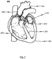
- such natural lumen access and delivery systems typically are configured, for example, to reach the aortic valve location 212 inside of the heart 202 from an antegrade approach, i.e. performed in the normal direction of blood flow.
- An antegrade approach generally requires navigating instrumentation through the right ventricle 222, the left atrium, and the left ventricle 220 of the beating heart 202, by way of the mitral valve 210.
- a retrograde approach i.e. an access performed backward or against the usual direction of blood flow, is an alternative to reach the aortic valve location 212 inside of the heart 202.
- a retrograde approach generally requires navigating instrumentation along the aortic arch, from the descending aorta 204 to the ascending aorta 206 and adjacent the aortic valve 212.
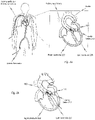
- FIG. 2a A transarterial access to the heart 202 of a patient as an example for a retrograde approach is schematically shown in Fig. 2a .
- a heart valve stent 100 is advanced with the aid of a medical catheter delivery system (only schematically shown) via the femoral artery to the aortic valve 212.
- a retrograde approach cannot be used in patients who have small or tortuous femoral or iliac vessels or severe peripheral vascular disease such as persons with previous aortobifemoral grafting. Rather, for such patients, an antegrade approach, for example a transarterial, transfemoral or transsubclavian approach, is preferred, whereby the surgeon creates a transcutaneous access to the region around the apex 224 of the beating heart 202 with a surgical thoracotomy, followed by direct access to the left ventricle 220 using a needle or other puncture device aimed to access the left ventricle 220 around the left ventricular apex 224.
- a transarterial, transfemoral or transsubclavian approach is preferred, whereby the surgeon creates a transcutaneous access to the region around the apex 224 of the beating heart 202 with a surgical thoracotomy, followed by direct access to the left ventricle 220 using a needle or other puncture device aimed to
- FIG. 2b Aspects of an antegrade (transapical) access procedure are illustrated in Fig. 2b , wherein the pericardium is opened by using a needle device for puncturing the muscular heart wall to gain access of the left ventricle 220 around the location of the left ventricular apex 224.
- a guidewire 180 may be advanced toward and through the aortic valve 212 to assist with diagnostic and interventional aspects of the procedure.
- the apex 224 is closed, for example, by using a purse-string suture technique.
- a purse-string suture is a continuous suture placed in a circle about a round wound or punctures which needs to be closed. The opening is closed by tightly drawing the ends of the suture together.
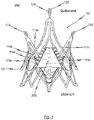
- FIG. 3 An exemplary embodiment of a heart valve prosthesis 150 comprising a heart valve stent 100 and a prosthetic heart valve 200 affixed thereto is illustrated in Fig. 3 .
- the exemplary embodiment of a heart valve prosthesis 150 as schematically illustrated in Fig. 3 is adapted for the treatment of a narrowed cardiac valve or a cardiac valve insufficiency.
- the heart valve prosthesis 150 comprises a heart valve stent 100 which exhibits an expandable structure which is able to transform from a first predefinable shape, in which the stent 100 is in a collapsed state, into a second predefinable shape in which the stent 100 is in an expanded state.
- the heart valve stent 100 together with a prosthetic heart valve 200 affixed thereto is introduced in a minimally invasive fashion into the body of a patient in its first shape using a catheter delivery system. During (antegrade or retrograde) insertion by way of a catheter delivery system, the prosthetic heart valve 200 affixed to the stent 100 is likewise in a collapsed state.
- the exemplary embodiment of a heart valve prosthesis 150 depicted in Fig. 3 is adapted to be introduced with a retrograde approach or an antegrade approach by way of a catheter delivery system to be described latter.
- the stent 100 Upon reaching the site of implantation in the patient's heart, the stent 100 transforms into its second (expanded) shape in which the valvular prosthesis 200 affixed to the stent 100 also unfolds and expands.
- the second expanded shape is a permanent shape that has been set by programming.
- Fig. 3 shows the exemplary embodiment of the heart valve prosthesis 150 in a completely expanded state.
- the stent 100 according to the exemplary embodiment of the heart valve prosthesis 150 depicted in Fig. 3 has a total of three positioning arches 115a, 115b, 115c which assume a function of self-positioning the stent 100 into the plane of a native pulmonary valve ( valva trunci pulmonalis ) or a native aortic valve ( valva aortae ) .
- Each of the positioning arches 115a, 115b, 115c exhibits a rounded head portion 120 which are designed to engage in the pockets T of a (diseased) native cardiac valve to be treated during positioning of the stent 100 at the site of implantation in the heart.
- FIG. 7a to 7c illustrate schematically an exemplary embodiment of a catheter tip of a medical catheter delivery system for retrograde insertion of an expandable heart valve prosthesis in different functional states to illustrate a implantation procedure of a heart valve prosthesis accommodated in the catheter tip.
- the provision of a total of three positioning arches 115a, 115b, 115c also provides rotational accuracy, symmetry and stability.
- the stent 100 is of course not limited to the use of a total of three positioning arches 115a, 115b, 115c.
- the head portions 120 of the positioning arches 115a, 115b, 115c, respectively pointing towards an inflow end region of the stent 100, are rounded so that the vascular wall will not be damaged when the positioning arches 115a, 115b, 115c engage in the pockets T of the native cardiac valve to be replaced.
- reference markers may be provided on or within the head portions 120 of the positioning arches 115a, 115b, 115c. Radio opaque markers or markers which can be activated by infrared or ultrasound lend themselves particularly well hereto.
- each positioning arch 115a, 115b, 115c of the heart valve stent 100 respectively exhibit an essentially U-shaped or V-shaped structure which is closed to the inflow end of stent 100. Accordingly, each positioning arch 115a, 115b, 115c has a total of two arms respectively extending from the head portion 120 of the associated positioning arch 115a, 115b, 115c towards an outflow end of stent 100. By doing so, each two adjoining arms of two neighbouring positioning arches 115a, 115b, 115c are connected to one another via a connecting portion.
- the stent 100 For implanting and explanting the stent 100 with a suitable catheter delivery system, the stent 100 comprises catheter retaining elements 123 preferably at its outflow end region.
- the catheter retaining elements 123 may comprise oval-shaped heads which each may comprise a corresponding oval-shaped eyelet 124.
- the shape of the catheter retaining elements 123 complements stent retaining elements of a crown on the catheter tip of a catheter delivery system used to implant/explant the stent 100.
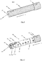
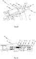
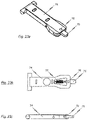
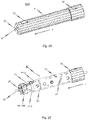
- FIG. 4 illustrates schematically an exemplary embodiment of a catheter tip of a medical catheter delivery system for retrograde insertion of an expandable heart valve prosthesis in a part-sectioned side elevation
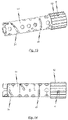
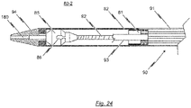
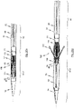
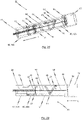
- a catheter tip of a medical catheter delivery system for antegrade insertion of an expandable heart valve prosthesis in a part-sectioned side elevation is illustrated schematically in Fig. 24 .
- the stent retaining elements of the catheter tip of a catheter delivery system may have protruding elements that are configured as a negative of the catheter retaining elements 123 provided preferably at the outflow end region of the stent 100.
- the protruding elements of the stent retaining elements of the catheter tip may be shaped to be complementary to the eyelets 124 of the catheter retaining elements 123 provided preferably at the outflow end region of the stent 100 and are configured as catheter retaining heads. This realization enables the protruding elements of the crown to form a releasable engagement with the outflow area of stent 100 to allow releasable attachment of the stent 100 to the catheter tip.
- the heart valve stent 100 of the exemplary embodiment of the heart valve prosthesis 150 is further provided with retaining arches 116a, 116b, 116c at which the prosthetic heart valve 200 is fastened in particular by way of a thread or a thin wire. It is easily recognized that the widening of the centre area and the inflow end region of the stent 100, at which the prosthetic heart valve 200 is disposed, achieves spreading of the prosthetic heart valve 200.
- Exemplary embodiments of a medical catheter delivery system suitable for introducing a heart valve prosthesis, for example a heart valve prosthesis 150 of the kind as shown in Fig. 3 , into a body of a patient are described in the following.
- the medical catheter delivery system for introducing an expandable heart valve prosthesis 150 into the body of a patient is constituted as catheter system having a catheter tip 80-1, 80-2 at a distal end portion of the catheter delivery system.
- the catheter tip 80-1, 80-2 is capable of accommodating at least partly a preferably tightly compressed heart valve prosthesis 150 or heart valve stent 100.
- the catheter system further comprises an operating handle 10-1, 10-2 at a proximal end portion of the catheter system.
- the operating handle 10-1, 10-2 is configured for manipulating the catheter tip 80-1, 80-2 which becomes necessary for releasing a heart valve prosthesis 150 accommodated in the catheter tip 80-1, 80-2, for example, at an implantation side inside the patient's body.
- the operating handle 10-1, 10-2 of the catheter system is operatively connected with the catheter tip 80-1, 80-2 by way of a catheter shaft 90.
- a catheter shaft 90 In case the catheter system is designed for retrograde access, preferably at least a distal end portion of the catheter shaft 90 is flexible enough such that the catheter tip 80-1 and the distal end portion of the catheter shaft 90 may pass the aortic arch, in particular during insertion through the aorta of a patient.
- FIG. 4 An exemplary embodiment of a catheter tip 80-1 of a medical catheter delivery system for retrograde (for example transarterial, transfemoral or transsubclavian) insertion of an expandable heart valve prosthesis 150 or an expandable heart valve stent 100 is described in the following with reference to Fig. 4 .
- FIG. 4 illustrates schematically an exemplary embodiment of a catheter tip 80-1 of a medical catheter delivery system for retrograde insertion of an expandable heart valve prosthesis (not shown in Fig. 4 ) in a part-sectioned side elevation.
- a heart valve prosthesis 150 of the kind as shown in Fig. 3 could be inserted into the body of a patient by way of the exemplary embodiment of a catheter tip 80-1 illustrated in Fig. 4 .
- the catheter tip 80-1 has a seat portion for accommodating a heart valve prosthesis 150 or a heart valve stent 100 to be inserted in its collapsed state. Furthermore, the catheter tip 80-1 is provided with stent retaining element 85 for releasably fixing a heart valve prosthesis 150 or a heart valve stent 100 in the seat portion of the catheter tip 80-1.
- the stent retaining element 85 comprises a crown having attachment elements 86 for releasably connecting with catheter retaining elements 123 of a heart valve prosthesis 150 or a heart valve stent 100 to be implanted.
- the stent retaining element 85 of the catheter tip 80-1 functionally serves as a "stent holder".
- the seat portion of the catheter tip 80-1 is constituted by at least one sleeve-shaped member.
- the seat portion of the catheter tip 80-1 comprises a total of two sleeve-shaped members: a first sleeve-shaped member 81 and a second sleeve-shaped member 82.
- the respective cross-sections of the two sleeve-shaped members 81, 82 are preferably identical to each other such that the first and second sleeve-shaped members 81, 82 can completely enclose a heart valve stent 100 or a heart valve prosthesis 150 accommodated in the catheter tip 80-1.
- the first and second sleeve-shaped members 81, 82 are movable relatively to each other and also relatively to the stent retaining element 85 (stent holder) used for releasably fixing a heart valve stent 100 or heart valve prosthesis 150 to the catheter tip 80-1.
- a first force transmitting member having a distal end portion connected to the first sleeve-shaped member 81 is provided.
- the first force transmitting member is allocated to the first sleeve-shaped member 81 of the catheter tip 80-1 and has a proximal end portion opposite to the distal end portion, the proximal end portion of the first force transmitting member being operatively connected to a corresponding (first) sliding member 30 of an operating handle 10-1, 10-2 of the catheter delivery system.
- An exemplary embodiment of an operating handle 10-1 having a corresponding (first) sliding member 30 for manipulating the first sleeve-shaped member 81 of the catheter tip 80-1 illustrated in Fig. 4 is described below with reference to Figs. 8 to 23 .
- a second force transmitting member having a distal end portion connected to the second sleeve-shaped member 82 is provided.
- the second force transmitting member is allocated to the second sleeve-shaped member 82 of the catheter tip 80-1 and has a proximal end portion opposite to the distal end portion, the proximal end portion being operatively connected to a corresponding (second) sliding member 40 of an operating handle 10-1 of the catheter deliver system.
- An exemplary embodiment of an operating handle 10-1 having a corresponding (second) sliding member 40 for manipulating the second sleeve-shaped member 82 of the catheter tip 80-1 illustrated in Fig. 4 is described below with reference to Figs. 8 to 23 .
- the first and/or second sleeve-shaped members 81, 82 may be moved relatively to each other and relatively to the stent retaining element 85 (stent holder) of the catheter tip 80-1.
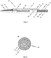
- Fig. 5 illustrates schematically an exemplary embodiment of a catheter shaft 90 of a medical catheter delivery system adapted for retrograde (for example transarterial, transfemoral or transsubclavian) insertion of a heart valve prosthesis 150.
- a medical catheter delivery system adapted for retrograde (for example transarterial, transfemoral or transsubclavian) insertion of a heart valve prosthesis 150.
- the first force transmitting member allocated to the first sleeve-shaped member 81 of the catheter tip 80-1 and operatively connected with a first sliding member 30 of the operating handle 10-1 may be constituted by a first catheter tube 91 defining a first lumen.
- the second force transmitting member allocated to the second sleeve-shaped member 82 of the catheter tip 80-1 and operatively connected with a second sliding member 40 of the operating handle 10-1 may be constituted by a further (second) catheter tube 92 defining a further (second) lumen.
- the second catheter tube 92 has a cross-sectional diameter less than the cross-sectional diameter of the first catheter tube 91.
- the first catheter tube 91 is disposed concentrically and coaxially with the second catheter tube 92 and the second catheter tube 92 is received within the first lumen defined by the first catheter tube 91.
- the stent retaining element 85 (stent holder) of the catheter tip 80-1 is preferably not axially movable relatively to the operating handle 10-1 of the catheter system. Rather, the stent retaining element 85 is preferably connected to an anchorage 45 of the operating handle 10-1 by using a further catheter tube 93 having a distal end portion connected to the stent retaining element 85, and further having a proximal end portion connected to an anchorage 45 of the operating handle 10-1.
- this further catheter tube 93 is also referred as "stent holder tube”.
- the stent holder tube 93 may have a cross-sectional diameter less than the cross-sectional diameter of the first catheter tube 91.
- the first catheter tube 91 may be disposed concentrically and coaxially with both, the stent holder tube 93 on the one hand and the second catheter tube 92 on the other hand.
- the stent holder tube 93 has a cross-sectional diameter less than the cross-sectional diameter of the first catheter tube 91 and greater than the cross-sectional diameter of the second catheter tube 92 such that the stent holder tube 93 is received within the first lumen defined by the first catheter tube 91.
- the second catheter tube 92 is preferably received within a passageway defined by the stent holder tube 93.
- the passageway defined by the stent holder tube 93 has a diameter sufficient to accommodate the second catheter tube 92 such that the second catheter tube 92 is movable relatively to the stent holder tube 93.
- the second lumen defined by the second catheter tube 92 has preferably a diameter sufficient to accommodate a guidewire 180.
- the second catheter tube 92 may be made from a rigid material including, for example, nitinol, stainless steel or a rigid plastic material.
- the material of the distal end portion of the second catheter tube 92 may have an increased flexibility compared to the material of the proximal end portion in order to allow the distal end portion of the catheter shaft 90 to pass the aortic arch during insertion of the catheter tip 80-1.
- the first catheter tube 91 may be a 12F-catheter tube. This particularly applies for a catheter delivery system designed for retrograde (for example transarterial, transfemoral or transsubclavian) access.
- the distal end portion of the second catheter tube 92 terminates in a soft catheter end tip 94 which preferably has an atraumatic shape.
- the soft catheter end tip 94 is provided with a channel aligned with the second lumen defined by the second catheter tube 92 such that a guidewire 180 accommodated within the second lumen defined by the second catheter tube 92 may pass through the channel of the soft catheter end tip 94.
- the second sleeve-shaped member 82 of the catheter tip 80-1 is connected to the soft catheter end tip 94 such that the opened end of the second sleeve-shaped member 82 faces in the proximal direction opposite to the direction of the soft catheter end tip 94, i.e. in the direction of an operating handle 10-1 of the catheter delivery system.
- the stent holder tube 93 is preferably made of a rigid material, for example, a rigid plastic material, stainless steel or nitinol.
- the distal end portion of the stent holder tube 93 terminates in the stent retaining element 85 and, in more detail, in a crown (stent holder) of the stent retaining element 85.
- the crown is preferably also made of a rigid material, for example, a rigid plastic material or stainless steel.
- the passageway defined by the stent holder tube 93 is aligned with a channel which passes through the crown (stent holder) of the stent retaining element 85.
- the second catheter tube 92 is accommodated in the passageway of the stent holder tube 93 and in the channel of the crown of the stent retaining element 85 such as to be movable relatively to the stent holder tube 93 and the crown (stent holder) of the stent retaining element 85.
- the first catheter tube 91 is preferably made of a bendable but inelastic material.
- the first catheter tube 91 may be at least partly made of a braided or non-braided catheter tube.
- the first catheter tube 91 is preferably adapted to transfer compression and tension forces from corresponding operating mechanisms (first sliding member 30) of an operating handle 10-1 of the catheter delivery system to the first sleeve-shaped member 81 of the catheter tip 80-1 without overly changing its total length.
- the distal end portion of the first catheter tube 91 preferably terminates at a flared section 83 as a transition to the section defining the first sleeve-shaped member 81 of the catheter tip 80-1.
- the flared section 83 and the first sleeve-shaped member 81 may be formed integrally and may be connected to the distal end portion of the first catheter tube 91.
- the flared section 83 may constitute the first sleeve-shaped member 81 of the catheter tip 80-1.
- the first sleeve-shaped member 81 and the flared section 83 of the first catheter tube 91 may be all of the same material and originating from the same raw tube prior to a widening process so that the flared section 83 and the first sleeve-shaped member 81 may be the same elements.
- a catheter delivery system designed for retrograde (for example transarterial, transfemoral or transsubclavian) access comprises a catheter tip 80-1 for accommodating a heart valve stent 100, with a heart valve prosthesis 150 fastened to it.
- the catheter tip 80-1 consists of a first sleeve-shaped member 81, particularly for accommodating positioning arches 115a, 115b, 115c of a heart valve stent 100, and a second sleeve-shaped member 82, in particular for accommodating retaining arches 116a, 116b, 116c and a heart valve prosthesis 150 fastened to it.
- the catheter delivery system in accordance with some embodiments of the present disclosure is adapted to release an expandable heart valve prosthesis 150 accommodated in the catheter tip 80-1 of the catheter delivery system in a previously definable sequence of events in steps.
- the first and second sleeve-shaped members 81, 82 of the catheter tip 80-1 are movable relatively to each other and relatively to the stent retaining element 85 (stent holder) of the catheter tip 80-1.
- a manipulation of the respective sleeve-shaped members 81, 82 of the catheter tip 80-1 can be affected on actuation of respective sliding members 30, 40 of the operating handle 10-1 with which the sleeve-shaped members 81, 82 of the catheter tip 80-1 are operatively connected.
- the first sleeve-shaped member 81 of the catheter tip 80-1 is operatively connected with a first sliding member 30 of a corresponding operating handle 10-1 by way of first force transmitting mechanism, for example, a first catheter tube 91.
- the second sleeve-shaped member 82 of the catheter tip 80-1 is operatively connected with a corresponding second sliding member 40 of the operating handle 10-1 by way of second force transmitting mechanism, for example, further (second) catheter tube 92.
- the stent retaining element 85 (stent holder) of the catheter tip 80-1 is preferably not movable in the longitudinal direction relatively to the operating handle 10-1.
- the stent retaining element 85 is preferably not operatively connected with a corresponding (manipulatable) sliding member of the operating handle 10-1. Rather, according to preferred embodiments of the present disclosure, the stent retaining element 85 of the catheter tip 80-1 is connected, for example by way of a stent holder tube 93, with an anchorage 45 of the operating handle 10-1.
- the catheter tip 80-1 is illustrated in a first functional state, in which the catheter tip 80-1 and, for example a heart valve prosthesis 150 accommodated in it, can be inserted into the patient transarterially, transfemorally or transsubclavianally and advanced via the aorta to the implantation side. Accordingly, in the first functional state, the catheter tip 80-1 is completely closed whereby the respective open end sections of the two sleeve-shaped members 81, 82 of the catheter tip 80-1 abut against each other.
- the two sleeve-shaped members 81, 82 of the catheter tip 80-1 may also at least partly overlap telescopically. Accordingly, in the first functional state of the catheter tip 80-1, the two sleeve-shaped members 81, 82 provide for a seat portion adapted for accommodating an at least partly preferably tightly compressed heart valve prosthesis 150.
- the catheter tip 80-1 On reaching an implantation location in the patient's body, the catheter tip 80-1 is transferred from its first functional state into a second functional state by transferring the first sliding member 30 of the operating handle 10-1 from a first position into a second position.
- the longitudinal (axial) displacement stroke transferred by actuation of the first sliding member 30 to the operatively connected first sleeve-shaped member 81 of the catheter tip 80-1 affects a axial displacement of the first sleeve-shaped member 81 relative to the stent retaining element 85 (stent holder) and the second sleeve-shaped member 82 of the catheter tip 80-1 in a proximal direction, thus towards the operating handle 10-1.
- the longitudinal (axial) displacement stroke executed on the first sleeve-shaped member 81 of the catheter tip 80-1 during transition from the first functional state to the second functional state by the first sliding member 30 via a corresponding first force transmitting mechanism is previously defined so that the first sleeve-shaped member 81 is displaced relatively to the stent retaining element 85 (stent holder) of the catheter tip 80-1 in the proximal direction just so far that only a predetermined portion of a heart valve prosthesis 150 housed in the catheter tip 80-1 would be released.
- the distal end portion of the first sleeve-shaped member 81 of the catheter tip 80-1 is still covering the stent retaining element 85 (stent holder) of the catheter tip 80-1, so that an engagement between catheter retaining elements 123 provided at a heart valve prosthesis 150 accommodated in the catheter tip 80-1 and the stent retaining element 85 (stent holder) of the catheter tip 80-1 would be secured.
- the retaining arches 116a, 116b, 116c of a heart valve stent 100 housed in the catheter tip 80-1 with a prosthetic heart valve 200 fastened to it would continue to be housed in its folded state in the second sleeve-shaped member 82 of the catheter tip 80-1.
- the positioning arches 115a, 115b, 115c of a heart valve stent 100 housed in the catheter tip 80-1 are released in the second functional state of the insertion system.
- the positioning arches 115a, 115b, 115c radially expand as a result of the radial forces acting on then and can thus be positioned in the pockets T of a native heart valve.
- the catheter tip 80-1 of the catheter delivery system is transferred from the second functional state into a third functional state. This is done by manipulation of the second sliding member 40 of the operating handle 10-1 which is operatively connected with the second sleeve-shaped member 82 of the catheter tip 80-1, for example by way of a second catheter tube 92.
- the second sleeve-shaped member 82 of the catheter tip 80-1 is axially moved relatively to the stent retaining element 85 (stent holder) of the catheter tip 80-1 by a previously established longitudinal (axial) displacement stroke in a distal direction, thus away from the operating handle 10-1.
- the longitudinal (axial) displacement stroke acting on the second sleeve-shaped member 82 is chosen so that the second sleeve-shaped member 82 no longer covers the inflow region of a heart valve prosthesis 150 housed in the catheter tip 80-1, and thus releases the inflow region of the heart valve prosthesis 150. Due to the action of radial forces, the inflow region of the heart valve prosthesis 150 unfolds completely.
- the distal end region of the first sleeve-shaped member 81 continues to cover the outflow end region of the heart valve prosthesis 150 and, in particular, the stent retaining element 85 (stent holder) of the catheter tip 80-1, so that an engagement between catheter retaining elements 123 of a heart valve prosthesis 150 housed in the catheter tip 80-1 and the stent retaining element 85 (stent holder) of the catheter tip 80-1 is secured and the outflow end region of the heart valve prosthesis 150 is still in its folded state.
- the maintained anchorage of the heart valve prosthesis 150 to the catheter tip 80-1 also allows an explantation of the heart valve prosthesis 150 that is already partially unfolded by returning the catheter tip 80-1 from the third functional state by appropriate manipulation of the first and second sliding members 30, 40 of the operating handle 10-1, to the second functional state and then by suitable actuation of the first sliding member transferred to the first functional state.
- the catheter tip 80-1 is transferred from the third functional state into a fourth functional state by moving the first sliding member 30 of the operating handle 10-1 further from the second position to a third position.
- the manipulation of the first sliding member 30 results in a further defined movement of the first sleeve-shaped member 81 of the catheter tip 80-1 relative to the stent retaining element 85 (stent holder) of the catheter tip 80-1 in a proximal direction, thus towards the operating handle 10-1.
- the longitudinal (axial) displacement stroke executed on the first sleeve-shaped member 81 is chosen so that the distal end of the first sleeve-shaped member 81 no longer covers the stent retaining element 85 (stent holder) of the catheter tip 80-1, as a result of which an engagement between catheter retaining elements 123 of a heart valve prosthesis 150 housed in the catheter tip 80-1 and the stent retaining element 85 (stent holder) of the catheter tip 80-1 can be released, which would also lead to a complete release of the outflow end region of the heart valve prosthesis 150 and a complete separation of the heart valve prosthesis 150 from the catheter tip 80-1 and correspondingly to a complete unfolding of the heart valve prosthesis 150.
- FIG. 6a A further exemplary embodiment of a catheter tip 80-1 of a catheter delivery system for retrograde (for example transarterial, transfemoral or transsubclavian) insertion of an expandable heart valve prosthesis 150 is shown in different functional states in Figs. 6a to 6f .
- the exemplary embodiment of the catheter tip 80-1 is shown in its first functional state in Fig. 6a , in which the catheter shaft 90 with the catheter tip 80-1 and a heart valve prosthesis 150 accommodated in the catheter tip 80-1 can be inserted into the patient transaterially or transfemorally and advanced, for example, via the aorta to the implantation side at the heart.
- the catheter tip 80-1 In the first functional state of the catheter tip 80-1 in accordance with Fig. 6a , the catheter tip 80-1 is completely closed, whereby the two sleeve-shaped members 81, 82 of the catheter tip 80-1 abut. According to the exemplary embodiment of the catheter tip 80-1 depicted in Figs. 6a to 6f , the two sleeve-shaped members 81, 82 of the catheter tip 80-1 have an equal outer cross-sectional diameter, thereby not forming a step in the state depicted in Fig. 6a .
- the respective inner diameters of the sleeve-shaped members 81, 82 are chosen so that compressed retaining arches 116a, 116b, 116c of a heart valve stent 100 can be housed in the second sleeve-shaped member 82.
- Compressed positioning arches 115a, 115b, 115c of a heart valve stent 100 accommodated in the catheter tip 80-1 would be housed between the second sleeve-shaped member 82 and the first sleeve-shaped member 81 and would be held together in the compressed form.
- the retaining region of the stent 100 at the stent's outflow end is fixed with stent retaining element 85 (stent holder) provided at a proximal end region of the catheter tip 80-1.
- catheter retaining elements 123 e.g. retaining rings etc.
- catheter retaining elements 123 provided at a corresponding retaining region of the heart valve stent 100 are engaged with the stent retaining element 85 (stent holder) of the catheter tip 80-1.
- the stent retaining element 85 (stent holder) of the catheter tip 80-1 are covered by the first sleeve-shaped member 81 of the catheter tip 80-1 in the first functional state shown in Fig. 6a , so that an engagement between catheter retaining elements 123 provided at a heart valve stent 100 accommodated in the catheter tip 80-1 and the stent retaining element 85 (stent holder) of the catheter tip 80-1 would be possible.
- the first functional state of the catheter tip 80-1 shown in Fig. 6a is maintained during a retrograde (for example transarterial, transfemoral or transsubclavian) insertion procedure.
- a retrograde for example transarterial, transfemoral or transsubclavian
- the catheter tip 80-1 is transferred from the first functional state shown in Fig. 6a to a second functional state shown in Fig. 6b by transferring a first sliding member 30 of an operating handle 10-1 operatively connected with the first sleeve-shaped member 81 of the catheter tip 80-1 from a first position into a second position.
- the longitudinal (axial) displacement stroke transferred by actuation of the first sliding member 30 to the first sleeve-shaped member 81 of the catheter tip 80-1 affects a displacement of the first sleeve-shaped member 81 relative to the stent retaining element 85 (stent holder) of the catheter tip 80-1 in the proximal direction, thus towards the operating handle 10-1.
- the longitudinal (axial) displacement stroke executed on the first sleeve-shaped member 81 of the catheter tip 80-1 during the transition from the first functional state (see Fig. 6a ) to the second functional state (see Fig. 6b ) by the first sliding member 30 via corresponding first force transmitting mechanism is previously defined so that the first sleeve-shaped member 81 is displaced relatively to the stent retaining element 85 (stent holder) of the catheter tip 80-1 in the proximal direction just so far that positioning arches 115a, 115b, 115c of a heart valve stent 100 housed in the catheter tip 80-1 would be released.
- a distal end of the first sleeve-shaped member 81 of the catheter tip 80-1 still covers the stent retaining element 85 (stent holder) of the catheter tip 80-1, so that the engagement between catheter retaining elements 123 provided at a retaining region of the heart valve stent 100 and the stent retaining element 85 (stent holder) of the catheter tip 80-1 would be secured.
- the first sleeve-shaped member 81 of the catheter tip 80-1 has already moved by a first predetermined amount of movement in a proximal direction, and thus towards the operating handle 10-1 of the catheter delivery system, leading to a release of positioning arches 115a, 115b, 115c of a stent 100 accommodated in the catheter tip 80-1.
- These positioning arches 115a, 115b, 115c of the stent 100 are positioned - where necessary by a suitable rotation of the stent retaining element 85 (stent holder) of the catheter tip 80-1 - in the pockets T of the native heart valve.
- the catheter tip 80-1 of the catheter delivery system is transferred from its second functional state (see Fig. 6b ) into its third functional state (see Fig. 6c ).
- the distal end region of the first sleeve-shaped member 81 continues to cover the stent retaining element 85 (stent holder) of the catheter tip 80-1, so that the engagement between catheter retaining elements 123 of a stent 100 housed in the catheter tip 80-1 and the stent retaining element 85 (stent holder) of the catheter tip 80-1 is secure and the outflow region of the stent 100 is still in its folded-up state.
- This anchorage of the stent 100 to the catheter tip 80-1 of the catheter delivery system allows an explantation of a stent 100 that is already partially unfolded by returning the catheter tip 80-1 from the third functional state, by appropriate manipulation of the second sliding member 40 of the operating handle 10-1, to the second functional state and then by suitable actuation of the first sliding member 30 transfer to the first functional state.
- the catheter tip 80-1 is transferred from the third functional state shown in Fig. 6c into the fourth functional state shown in Fig. 6d , by turning the first sliding member 30 of the operating handle 10-1 further from the second position to the third position.
- This manipulation of the first sliding member 30 results in a further defined movement of the first sleeve-shaped member 81 of the catheter tip 80-1 relative to the stent retaining element 85 of the catheter tip 80-1 in a proximal direction, i.e. thus towards the operating handle 10-1.
- the longitudinal (axial) displacement stroke executed on the first sleeve-shaped member 81 of the catheter tip 80-1 is chosen so that the distal end of the first sleeve-shaped member 81 no longer covers the stent retaining element 85 (stent holder), as a result of which an engagement between catheter retaining elements 123 of a stent 100 housed in the catheter tip 80-1 and the stent retaining element 85 (stent holder) can be released, which would also lead to a complete release of the outflow region of the stent 100 and a complete separation of the stent 100 from the catheter tip 80-1 and correspondingly to a complete unfolding of the stent 100 with a prosthetic heart valve 200 attached thereto.
- a stent holder tube 93 is used for connecting the stent retaining element 85 (stent holder) of the catheter tip 80-1 to an anchorage 45 fixed to a body portion of the operating handle 10-1.
- the stent holder tube 93 has a distal end connected to the stent retaining element 85 (stent holder) of the catheter tip 80-1, a proximal end connected to the body portion of the operating handle 10-1 and a passageway extending through the stent holder tube 93.
- an extension portion 93' of the stent holder tube 93 is provided, said extension portion 93' extending from the distal end of the stent retaining element 85 (stent holder) to a support section 94.
- the support section 94 may be a tapered portion which is completely accommodated in the second sleeve-shaped member 82 of the catheter tip 80-1 when the catheter tip 80-1 is in its first and second functional state (see Figs. 6a and 6b ).
- the stent holder tube 93 and its extension 93' have a cross-section less than the cross-section of the first catheter tube 91 and greater than the cross-section of the second catheter tube 92 (not shown in Figs. 6a to 6f ), wherein the first catheter tube 91 is disposed concentrically and coaxially with the stent holder tube 93 thereby accommodating the stent holder tube 93 such that the first catheter tube 91 is moveable relative to the stent holder tube 93.
- the passageway of the stent holder tube 93 may have a diameter sufficient to accommodate the second catheter tube 92 such that the second catheter tube 92 is moveable relative to the stent holder tube 93.
- Fig. 6e shows a side elevation of the embodiment of the catheter tip 80-1 in accordance with Figs. 6a to 6d , whereby the catheter tip 80-1 is in its state after releasing a stent 100, which was accommodated in the catheter tip 80-1.
- the second sleeve-shaped member 82 of the catheter tip 80-1 is moved proximally, i.e. in the direction of the operating handle 10-1, by manipulation of the second sliding member 40 of the operating handle 10-1.
- Fig. 6f shows a side elevation of the embodiment of the catheter tip 80-1 in accordance with Figs. 6e , whereby the catheter tip 80-1 is in its state ready to be removed again from the body of the patient.
- the first sleeve-shaped member 81 of the catheter tip 80-1 is pushed by manipulation of the first sliding member 30 of the operating handle 10-1 such that the first sleeve-shaped member 81 is in its most distal position, in which the distal end of the first sleeve-shaped member 81 abuts against the proximal end of the second sleeve-shaped member 82 without any gap or step there between.
- the distal end of the first sleeve-shaped member 81 and the proximal end of the second sleeve-shaped member 82 are supported by the already mentioned support section 94.
- the medical device is adapted for the treatment of a heart valve defect, in particular a heart valve failure or a heart valve stenosis in a patient.
- the medical device for the treatment of a heart valve defect comprises a catheter delivery system for introducing an expandable heart valve prosthesis into the body of a patient.
- the catheter delivery system comprises at least one sleeve-shaped member at a distal end portion of the catheter delivery system, the at least one sleeve-shaped member being part of a catheter tip of the catheter delivery system and capable of receiving at least partly a tightly compressed heart valve prosthesis.
- the catheter tip of the catheter delivery system is provided with a total of two sleeve-shaped members, as will be described in more detail below with reference to Figs. 7a to 7c .
- the catheter delivery system further comprises an operating handle, for example an operating handle 10-1 of the kind as illustrated in Fig. 8 .
- the operating handle 10-1 is disposed at a proximal end portion of the catheter delivery system and is adapted for manipulating the at least one sleeve-shaped member of the catheter tip.
- the operating handle may comprise a hand grip designed to be held by a user, and a manipulating part axially aligned with the hand grip.
- the manipulating part of the operating handle is rotatable relatively to the hand grip about a longitudinal axis defined by the operating handle.
- the operating handle comprises at least one sliding member operatively linked with the manipulating part of the operating handle by way of a cam mechanism such that, upon rotation of the manipulating part relative to the hand grip, the at least one sliding member moves axially in the direction of the longitudinal axis .
- FIG. 7a to 7c illustrate schematically an exemplary embodiment of a catheter tip 80-1 of a medical catheter delivery system for retrograde insertion of an expandable heart valve prosthesis 150 in different functional states for explaining an implantation procedure of the heart valve prosthesis 150 accommodated in the catheter tip 80-1.
- an operating handle (not shown in Figs. 7a to 7c ) is provided at a proximal end region of a catheter shaft 90 of a catheter delivery system.
- the operating handle preferably comprises a total of two sliding members: a first sliding member operatively connected to a first sleeve-shaped member 81 of the catheter tip 80-1, and a second sliding member operatively connected to a second sleeve-shaped member 82 of the catheter tip 80-1.
- the medical device for the treatment of a heart valve defect further comprises an expandable heart valve stent 100 accommodated in the catheter tip 80-1 of the catheter delivery system.
- a prosthetic heart valve 200 may be attached to the expandable heart valve stent 100 thereby forming a heart valve prosthesis 150.
- the exemplary embodiment of the medical device exhibits a catheter delivery system designed for retrograde (for example transarterial, transfemoral or transsubclavian) access.
- retrograde for example transarterial, transfemoral or transsubclavian
- the medical device it is also possible for the medical device to exhibit a catheter delivery system which it is designed for an antegrade access, as will be described later with reference to Figs. 25a to 25d .
- the medical device comprises a self-expandable heart valve stent 100 mounted in the catheter tip 80-1 of the catheter delivery system, to which a prosthetic heart valve 200 is fastened.
- a first functional state not shown in Figs. 7a to 7c , the heart valve stent 100 exhibits a first previously definable configuration, in which it is in its folded-together state.
- the heart valve stent 100 is designed to adopt a second previously definable configuration in an implanted state, in which it exists in its expanded state.
- the heart valve stent 100 is transferred sequentially, following a previously definable sequence of events in steps from its first previously defined configuration into its second previously defined configuration.
- the heart valve stent 100 that is used with the medical device in accordance with Figs. 7a to 7c exhibits a first retaining region, to which the prosthetic heart valve 200 is attached.
- the stent 100 comprises catheter retaining elements 123, for example, in the configuration of retaining rings, which can be brought into a releasable engagement with stent retaining element 85 (stent holder) of the catheter tip 80-1.
- the heart valve stent 100 may have a plurality of retaining arches 116 (in the embodiment depicted in Figs. 7a to 7c , the heart valve stent 100 is provided with a total of three retaining arches 160) to accommodate a prosthetic heart valve 200, and a plurality of positioning arches 115 (in the embodiment depicted in Figs.
- the heart valve stent 100 is provided with a total of three positioning arches) for automatic positioning of the stent 100 at the implantation site, whereby the respective positioning arches 115 of the stent 100 are designed in functional and structural respects to engage the pockets T of the native heart valve during an implantation procedure and in the implanted state of the stent 100, in particular from the second functional state of the catheter tip 80-1 of the catheter delivery system.
- each positioning arch 115 and its associated retaining arch 116 may have an essentially U or V-shaped structure, which is closed towards the inflow end of the stent 100.
- the stent 100 and the prosthetic heart valve 200 attached thereto which together with the catheter delivery system forms the basis of the medical device according to the present disclosure, is especially suitable for insertion into the body of a patient with minimal invasiveness.
- the distinctive feature of the heart valve stent 100 is that the positioning arches 115 of the stent 100 undertake the function of automatic positioning of the stent 100 with the prosthetic heart valve 200 attached to it in the aorta of the patient.
- the positioning arches 115 have radiused head sections, which engage in the pockets T of the insufficient heart valve to be replaced by the heart valve prosthesis 150 during positioning of the stent 100 at the implantation site.
- the provision of a total of at least three positioning arches 115 takes care of the necessary positioning accuracy in the rotary direction.
- the catheter tip 80-1 and the distal part of the catheter delivery system have been inserted by a puncture of the groin artery of the patient and the catheter tip 80-1 has been advanced to the implantation site with the aid of a guidewire 180.
- the catheter tip 80-1 be used is shown already in its second functional state in Fig. 7a .
- the first sleeve-shaped element 81 of the catheter tip 80-1 has already moved by a first predetermined amount of movement in a proximal direction, and thus towards an operating handle 10-1 of the catheter delivery system, leading to a release of the positioning arches 115 of the heart valve stent 100 accommodated in the catheter tip 80-1.
- These already expanded positioning arches 115 of the stent 100 shown in Fig. 7a are positioned - where necessary by a suitable rotation of the catheter tip 80-1 - in the pockets T of the native heart valve.
- the catheter tip 80-1 of the catheter delivery system is transferred from its second functional state (see for example Fig. 6b ) into its third functional state (see for example Fig. 6c ).
- Fig. 7b shows the catheter tip 80-1 of the catheter delivery system in accordance with Fig. 7a , in which the second sleeve-shaped member 82 of the catheter tip 80-1 has been displaced in a distal direction so that the first retaining region of the stent 100 with the retaining arches 116 and the prosthetic heart valve 200 attached to them are released.
- These components retaining arches 116 and prosthetic heart valve 200 attached thereto) are opened as a result of radial forces attacking on them, whereby the leaflets V of the native heart valve are clamped between the positioning arches 115 and the retaining arches 116 of the heart valve stent 100.
- the catheter tip 80-1 of the catheter delivery system is then transferred from its third functional state into its fourth functional state, as has previously been described, for example with reference to Fig. 6d .
- Fig. 7c shows the effect of a transfer of the catheter tip 80-1 of the catheter delivery system into its fourth functional state on the prosthetic heart valve 200 and the heart valve stent 100.
- catheter tip 80-1 and the distal portion of the catheter delivery system are removed again from the body of the patient.
- the leaflets V of the native (insufficient) heart valve is pressed against the vessel wall at the same time due to the self-expanding characteristic of the stent 100, as can be seen in particular in Fig. 7c .
- the semi-lunar leaflets V of the native heart valve are clamped between the positioning arches 115 and the retaining arches 116 of the heart valve stent 100 because of the expansion of the stent 100, in addition to which the prosthetic heart valve 200 is optimally positioned and is stably anchored.
- the operating handle 10-1 comprises a hand grip 11 designed to be held by a user, and a manipulating part 12 axially aligned with the hand grip 11.
- the manipulating part 12 of the operating handle 10-1 is rotatable relatively to the hand grip 11 about a longitudinal axis L defined by the operating handle 10-1.
- the operating handle 10-1 comprises at least one sliding member 30, 40 operatively linked with the manipulating part 12 of the operating handle 10-1 by way of a cam mechanism 50 such that, upon rotation of the manipulating part 12 relative to the hand grip 11, the at least one sliding member 30, 40 moves axially in the direction of the longitudinal axis L.
- the cam mechanism 50 is integrated into the operating handle 10-1 and is configured for transforming a rotary motion of the manipulating part 12 relative to the hand grip 11 into a linear motion of the at least one sliding member 30, 40 relative to the hand grip 11.
- the manipulating part 12 of the operating handle 10-1 is a rotating wheel designed to be gripped by a user with one of its hands, whereas the other hand holds the hand grip 11.
- the cam mechanism 50 comprises a cylindrical member 51 connected with the manipulating part 12 of the operating handle 10-1, wherein the cylindrical member 51 comprises at least one cam groove 31, 41.
- the cam mechanism 50 further comprises at least one pin member 32, 42 having a first end portion connected with the at least one sliding member 30, 40, and a second end portion opposite to the first end portion, the second end portion of the at least one pin member 32, 42 engaging the at least one cam groove 31, 41 such that, upon rotation of the manipulating part 12 relative to the hand grip 11, the at least one pin member 32, 42 follows a cam profile defined by the at least one cam groove 31, 41.
- the hand grip 11 of the operating handle is formed as a jacket.
- the cylindrical member 51 of the cam mechanism 50 is at least partly disposed concentrically and coaxially with the hand grip 11, wherein the cylindrical member 51 of the cam mechanism 50 is rotatable relatively to the hand grip 11.
- the cylindrical member 51 of the cam mechanism 50 is at least partly hollow.
- the cam mechanism 50 of the operating handle 10-1 comprises a body member 52 disposed concentrically and coaxially with the hollow cylindrical member 51, wherein the body member 52 comprises a cylindrical portion 52a having a diameter less than an inner diameter of the hollow cylindrical member 51, the cylindrical portion 52a being at least partly received in the interior of the hollow cylindrical member 51 such that the hollow cylindrical member 51 is rotatable relatively to the body member 52.
- the body member 52 is provided with at least one flange 53 for preventing axial movement of the manipulating part 12 relative to the body member 52.
- FIG. 8 to 23 Reference is made in the following in particular to Figs. 8 to 23 for explaining an exemplary embodiment of an operating handle 10-1 of a medical catheter delivery system designed for retrograde (for example transarterial, transfemoral or transsubclavian) insertion of an expandable heart valve prosthesis 150.
- a medical catheter delivery system designed for retrograde (for example transarterial, transfemoral or transsubclavian) insertion of an expandable heart valve prosthesis 150.
- Fig. 8 illustrates an exemplary embodiment of an operating handle 10-1 of a medical catheter delivery system for retrograde insertion of an expandable heart valve prosthesis.
- the operating handle 10-1 is provided at a proximal end portion of a catheter delivery system (not shown) and comprises a hand grip 11 designed to be held by a user.
- the operating handle 10-1 comprises a manipulating part 12 axially aligned with the hand grip 11.
- the manipulating part 12 is rotatable relatively to the hand grip 11 about a longitudinal axis L defined by the operating handle 10-1.
- the manipulating part 12 is a rotating wheel designed to be gripped by a user with one of its hands, whereas the other hand holds the hand grip 11.
- the operating handle 10-1 according to the exemplary embodiment depicted in Figs. 8 to 23 further comprises at least one sliding member 30, 40 operatively linked with the manipulating part 12 of the operating handle 10-1.
- the at least one sliding member 30, 40 is operatively connected with a sleeve-shaped member 81, 82 of a catheter tip 80-1 (not shown in Figs. 8 to 23 ) connected with the operating handle 10-1.
- the operating handle 10-1 is provided with a total of two sliding members: a first sliding member 30 which is operatively linked with the manipulating part 12 of the operating handle 10-1 and operatively connected with a first sleeve-shaped member 81 of the catheter tip 80-1, and a second sliding member 40 which is operatively linked with the manipulating part 12 of the operating handle 10-1 and operatively connected with a second sleeve-shaped member 82 of the catheter tip 80-1.
- Figs. 17a, b illustrate exemplary embodiments of sliding members 30, 40 adapted to be utilized in the exemplary embodiment of the operating handle 10-1 in accordance with Fig. 8 .
- a first sliding member 30 preferably comprises a body having a first cylindrical portion 30' and a second cylindrical portion 30".
- Fig. 16 illustrates how the sliding members 30, 40 are received within the operating handle 10-1.
- the first cylindrical portion 30' of the first sliding member 30 is connected (with of a screw 2) with a proximal end portion of a first catheter tube 91 acting as force transmitting mechanism.
- the distal end portion of the first catheter tube 91 is preferably connected with a first sleeve-shaped member 81 of a catheter tip 80-1 (not shown in Fig. 16 ).
- FIG. 17b An exemplary embodiment of a second sliding member 40 of the operating handle 10-1 according to some embodiments of the present disclosure is shown in Fig. 17b .
- the second sliding member 40 may also comprise a body having a first cylindrical portion 40' and a second cylindrical portion 40".
- the first cylindrical portion 40' of the second sliding member 40 is connected (with a screw 3) with a proximal end portion of a second catheter tube 92 acting as force transmitting mechanism.
- the distal end portion of the second catheter tube 92 is preferably connected with a second sleeve-shaped member 82 of a catheter tip 80-1 (not shown in Fig. 16 ).
- the first and second sliding members 30, 40 are respectively provided with a corresponding pin member 32, 42.
- Each of the two pin members 32, 42 has a first end portion connected with a corresponding one of the two sliding members 30, 40, and a second end portion opposite to the first end portion.
- the first and second sliding members 30, 40 are operatively linked with the manipulating part 12 of the operating handle 10-1 by way of a cam mechanism 50.
- the cam mechanism 50 is adapted to transform a rotary motion of the manipulating part 12 of the operating handle 10-1 relative to the hand grip 11 into a linear motion of the first and/or second sliding member 30, 40 relative to the hand grip 11.
- the cam mechanism 50 is integrated into the operating handle 10-1 and is configured for transforming a rotary motion into a linear motion.
- the cam mechanism 50 comprises a cylindrical member 51 and a body member 52.
- An exemplary embodiment of the cylindrical member 51 of the cam mechanism 50 is illustrated in Figs. 13 and 14
- Fig. 15 shows an exemplary embodiment of a body member 52 of the cam mechanism 50.
- the cam mechanism 50 may comprise an at least partly hollow cylindrical member 51 connected with the manipulating part 12 of the operating handle 10-1.
- the at least partly hollow cylindrical member 51 and the manipulating part 12 of the operating handle 10-1 are formed integrally, i.e., made from one piece.
- the cylindrical member 51 of the cam mechanism 50 is at least partly disposed concentrically and coaxially with the (jacked-like) hand grip 11, wherein the cylindrical member 51 is rotatable relatively to the hand grip 11.
- the cam mechanism 50 further comprises a body member 52 of the kind as shown in Fig. 15 .
- the body member 52 may be at least partly hollow such that the sliding members 30, 40 of the operating handle 10-1 are accommodatable within the body member 52 in a manner that the sliding members 30, 40 are axially movable relatively to the body member 52.
- the respective sliding members 30, 40 are preferably designed such as to be guided by an inner surface of the hollow body member 52.
- Fig. 10 illustrates the exemplary embodiment of the operating handle 10-1 in accordance with Fig. 8 without hand grip wherein 11.
- Fig. 15 illustrates the body member 53 of the cam mechanism 50 utilized in the exemplary embodiment of the operating handle 10-1 in accordance with Fig. 8 in a perspective elevation.
- the body member 52 comprises a cylindrical portion 52a having a diameter less than an inner diameter of the hollow cylindrical member 51.
- the cylindrical portion 52a of the body member 52 is at least partly received in the interior of the hollow cylindrical member 51 such that the hollow cylindrical member 51 is rotatable relatively to the body member 52.
- the body member 52 further comprises a portion 52b which is intended to be fixed to the hand grip 11 of the operating handle 10-1.
- the portion 52b of the body member 52 which is fixed to the hand grip 11 in an assembled state of the operating handle 10-1, is cylindrical and has at least one portion having a diameter equal to or substantially equal to the outer diameter of the hollow cylindrical member 51.
- the (jacket-like) hand grip 11 is at least partly disposed around the cylindrical portion 52b of the body member 52 such as to be concentrically and coaxially with the cylindrical portion 52b.
- the cylindrical member 51 comprises - for each sliding member 30, 40 of the operating handle 10-1 - a corresponding cam groove 31, 41.
- the second end portions of the corresponding pin members 32, 42 of the sliding members 30, 40 engage with a corresponding cam groove 31, 41 provided in the cylindrical member 51 of the cam mechanism 50.
- the respective pin members 32, 42 follow a cam profile defined by the corresponding cam groove 31, 41.
- the manipulating part 12 of the operating handle 10-1 may be formed as a rotating wheel rotating wheel having a diameter greater than the diameter of the cylindrical member 51 of the cam mechanism 50.
- the hand grip 11 of the operating handle 10-1 may be formed as a jacket (see Figs. 10a and 10b), wherein the cylindrical member 51 of the cam mechanism 50 is at least partly disposed concentrically and coaxially with the hand grip 11 and wherein the cylindrical member 51 of the cam mechanism 50 is rotatable relatively to the hand grip 11.
- the cylindrical member 51 of the cam mechanism 50 is preferably at least partly hollow.
- the cam mechanism 50 preferably further comprises a body member 52 serving as an anchorage of the operating handle.
- a proximal end section of a stent holder tube 93 is connected with the body member 52 of the operating handle, a distal end section of the stent holder tube being fixed to stent retaining element 85 of a catheter tip 80-1.
- the body member 52 is disposed concentrically and coaxially with the hollow cylindrical member 51.
- the operating handle 10-1 depicted in Figs. 8 to 23 is provided with at least one flange 53.
- the at least one flange 53 is connected with the body member 52 and abuts a rear side 54 of the manipulating part 12.
- the body member 52 is at least partly hollow, wherein the corresponding sliding members 30, 40 are received within the body member 52 such that the corresponding sliding members 30, 40 are axially movable relatively to the body member 52.
- the operating handle 10-1 depicted in Figs. 8 to 23 is adapted for manipulating a catheter tip 80-1 of a catheter delivery system.
- the operating handle 10-1 is designed for manipulating at least one sleeve-shaped member 81, 82 of a catheter tip 80-1 having a seat portion for accommodating a tightly compressed heart valve prosthesis 150.
- the cam mechanism 50 is provided with means for preventing a rotational movement of the sliding members 30, 40 relative to the body member 52.
- the means for preventing a rotational movement of the sliding members 30, 40 relative to the body member 52 comprises at least one elongated hole 33, 43 allocated to the sliding members 30, 40.
- the body member 52 is provided with a total of two elongated holes 33, 43, each extending parallel to the longitudinal axis L of the operating handle 10-1. Through each of the two elongated holes 33, 43 one pin member 32, 42 connected with one of the two sliding members 30, 40 extends (see Figs. 11 and 12 ).
- the exemplary embodiment of the operating handle 10-1 depicted in Figs. 8 to 23 is further provided with decoupling mechanism for selectively separating an operative linkage between at least one of the sliding members 30, 40 (preferably the second sliding member 40) and the manipulating part 12 of the operating handle 10-1.
- Figs. 20a to 20c also show a blocking mechanism for blocking a rotation movement of the at least one sliding member 30, 40 relative to the body member 52 upon rotation of the manipulating part 12 of the operating handle 10-1 relative to the hand grip 11.
- Figs. 18a and 18b illustrate a cross-sectional view of the operating handle in accordance with Fig. 8 for explaining an exemplary embodiment of decoupling mechanism for selectively separating an operative linkage between a sliding member 30, 40 of the cam mechanism 50 of the operating handle 10-1 and the manipulating part 12 of the operating handle 10-1.
- Fig. 19 illustrates a rear side (closed) of the exemplary embodiment of the operating handle 10-1 in accordance with Fig. 8 in a perspective elevation
- Figs. 20a to 20c illustrate the (open) rear side of the operating handle 10-1 in accordance with Fig. 19 for explaining a blocking mechanism for blocking a rotation movement of the at least one sliding member 30, 40 relative to the body member 52 upon rotation of the manipulating part 12 of the operating handle 10-1 relative to the hand grip 11.
- the decoupling mechanism 20 comprises a pin member manipulating element 21 operatively connected with one of the two pin members 32, 42 of the cam mechanism 50.
- the pin member manipulating element 21 is drivable from a first position, in which the corresponding pin member 32, 42 engages with the corresponding cam groove 31, 41, into a second position, in which the corresponding pin member 32, 42 is disengaged from the corresponding cam groove 31, 41.
- the decoupling mechanism 20 is adapted to interact with the second pin member 42 of the cam mechanism 50 which is connected with the second sliding member 40 (see Fig. 16 ) and which normally engages with the second cam groove 41 provided in the hollow cylindrical member 51 (see Figs. 11 to 14 ) such that, upon rotation of the manipulating part 12 relative to the hand grip 11, the second pin member 42 follows the cam profile defined by the second cam groove 41.
- the pin member manipulating element 21 comprises a lever arm 23 having a first end section operatively connected with the second pin member 42 and, in particular with the first end portion of the second pin member 42.
- the lever arm 23 of the pin member manipulating element 21 further has a second end section opposite to the first end section.
- the second end section of the lever arm 23 is operatively connected with an operating bar 24 for moving the lever arm 23 with the second pin member 42 connected thereon.
- the operating bar 24 of the decoupling mechanism 20 may be a rod-like element extending through the interior of the operating handle 10-1 and, in more detail, through the first and second sliding members 30, 40, received within the at least partly hollow body member 52, and also through the distal front side of the operating handle 12, such that the sliding members 30, 40 are movable relatively to the operating bar 24.
- a manipulation knob 25 is provided at the distal front side of the operating handle 12 for manipulating the operating bar 24 and thus the decoupling mechanism 20.
- the operating bar 24 preferably has a cross-section which allows a corresponding interaction with the second end section of the lever arm 23, for example, a rectangular cross-section. When turning the manipulation knob 25, the operating bar 24 is turned and the lever arm 23 is transferred from the position illustrated in Fig. 18a into the position illustrated in Fig. 18b .
- the second pin member 42 is movable by way of the operating bar 24 and the lever arm 23 operatively connected with the operating bar 24 from a coupled state, in which the second end portion of the pin member 42 engages with the corresponding cam groove 41 (see Fig. 18a ), into an uncoupled state, in which the second end portion of the pin member 40 disengages the cam groove 41 and in which the pin member manipulating element 21 at least partly engages with a further recess 49 provided in the body member 52 of the cam mechanism 50 thereby blocking an axial movement of the sliding member 40 relative to the body member 52 upon rotation of the manipulating part 12 of the operating handle 10-1 relative to the hand grip 11.
- the operating bar 24 is further provided with a blocking member 26.
- the operating bar 24 When rotating the operating bar 24 for moving the second pin member 42 from its coupled state into its uncoupled state, the operating bar 24 also manipulates the blocking member 26.
- the blocking member 26 moves a stop pin 27 radially outward such that the stop pin 27 abuts upon a body stop 28 provided at the cylindrical member 51 when the manipulating part 12 with the cylindrical member 51 is rotated relatively to the hand grip 11.
- the body stop 28 is formed as a pin axially extending from disc member 29.
- the disc member 29, which is part of the manipulating part 12 of the operating handle 10-1, is disposed at the flange 53 such as to be pivotably around a center pin 13 on the longitudinal axis L of the operating handle 10-1.
- the disc member 29 is biased via two tension springs 14.
- a screw 4 connected with the manipulating part 12 such as to extend radially in the interior of the manipulating part interacts with the body stop 28 upon rotation of the manipulating part 12 relative to the hand grip 11. Accordingly, a continued rotation of the manipulating part 12 relative to the hand grip 11 is blocked as soon as the decoupling mechanism 20 is activated.
- the spring mechanism constituted by the two tension springs 14 serves for resetting the manipulating part 12 when the manipulating part 12 is rotated relatively to the hand grip 11.
- the two tension springs 14 are stretched as a tension load is applied by means of the screw 4 connected with the manipulating part 12, when the screw 4 abuts the body stop 28 (see Fig. 20b ) and the manipulating part 12 is further rotated relatively to the hand grip 11 (see Fig. 20c ).
- the two tension springs 14 are designed to operate with a tension load applied by the screw 4. After applying a tension load to the tension springs 14 by means of the screw 4, the stretched tension springs 14 reset the manipulating part 12 of the operating handle into a state depicted in Fig. 20b , i.e., into a state where the screw 4 begins touching the body stop 28.
- the first sliding member 30 is operatively connected by way of a first catheter tube 91 with a first sleeve-shaped element 81 of the catheter tip 80-1
- the second sliding member 40 is operatively connected by way of a second catheter tube 92 with a second sleeve-shaped member 82 of the catheter tip 80-1. Accordingly, upon rotation of the manipulating part 12 of the operating handle 10-1 relative to the hand grip 11 of the operating handle 10-1, the first sliding member 30 together with the operatively connected first sleeve-shaped member 81 of the catheter tip 80-1 may be moved axially. Independent from this axial movement, the second sliding member 40 together with the operatively connected second sleeve-shaped member 82 of the catheter tip 80-1 may also be moved axially.
- the longitudinal (axial) displacement stroke acting on the first sleeve-shaped member 81 of the catheter tip 80-1 when turning the manipulating part 12 of the operating handle 10-1 relative to the hand grip 11 is defined by the cam profile of the first cam groove 31 with which the first pin member 32 of the first sliding member 30 engages.
- the longitudinal (axial) displacement stroke acting on the second sleeve-shaped member 82 of the catheter tip 80-1 when turning the manipulating part 12 of the operating handle 10-1 relative to the hand grip 11 is defined by the cam profile of the second cam groove 41 with which the second pin member 42 of the second sliding member 40 engages.
- the respective cam profiles of the first and second cam grooves 31, 41 are chosen such that the catheter tip 80-1 is manipulated as follows:
- the operating handle 10-1 allows for manipulating a catheter tip 80-1 operatively connected with the operating handle 10-1 such that the catheter tip 80-1 is transferred in a step-wise manner from its first functional state (see for example Fig. 6a ) into its second functional state (see for example Fig. 6b ) by turning the manipulating part 12 of the operating handle 10-1 relative to the hand grip 11 through a first angular range, and then from its second functional state (see for example Fig. 6b ) into its third functional state (see for example Fig. 6c ) by turning the manipulating part 12 of the operating handle 10-1 relative to the hand grip 11 through a second angular range following the first angular range, and then from its third functional state (see for example Fig. 6c ) into its fourth functional state (see for example Fig. 6d ) by turning the manipulating part 12 of the operating handle 10-1 relative to the hand grip 11 through a third angular range following the second angular range.
- the cam profiles of the first and second cam grooves 31, 41 are selected in a manner such that the longitudinal (axial) displacement stroke acting on the first sleeve-shaped member 81 of the catheter tip 80-1 when turning the manipulating part 12 of the operating handle 10-1 relative to the hand grip 11 through a first angular range is 20 mm to 34 mm in the proximal direction, preferably 24 mm to 30 mm in the proximal direction, and more preferably 26 mm to 28 mm in the proximal direction.
- the cam profiles of the first and second cam grooves 31, 41 are preferably selected in a manner such that the longitudinal (axial) displacement stroke acting on the second sleeve-shaped member 82 of the catheter tip 80-1 when turning the manipulating part 12 of the operating handle 10-1 relative to the hand grip 11 through a second angular range following the first angular range is 6 mm to 18 mm in the distal direction, preferably 9 mm to 15 mm in the distal direction, and more preferably 11 mm to 13 mm in the distal direction.
- the cam profiles of the first and second cam grooves 31, 41 are preferably selected in a manner such that the longitudinal (axial) displacement stroke acting on the first sleeve-shaped member 81 of the catheter tip 80-1 when turning the manipulating part 12 of the operating handle 10-1 relative to the hand grip 11 through a third angular range following the second angular range is 6 mm to 18 mm in the proximal direction, preferably 9 mm to 15 mm in the proximal direction, and more preferably 11 mm to 13 mm in the proximal direction.
- the operating handle 10-1 For subdividing a maximal available turning movement of the manipulating part 12 of the operating handle 10-1 when rotated relative to the hand grip 11 and for separating the respective angular ranges through which the manipulating part 12 is turnable relatively to the hand grip 11, the operating handle 10-1 according to the invention is provided with a corresponding locking mechanism 70.
- the locking mechanism 70 comprises at least one locking recess 71-1, 71-2 provided in the cylindrical member 51 of the cam mechanism 50. Furthermore, the locking mechanism 70 is provided with at least one engaging piece 72 operatively connected with the body member 52. The engaging piece 72 is adapted to releasably engage with the at least one locking recess 71-1, 71-2 thereby preventing continuous rotation of the cylindrical member 51 relative to the body member 52 of the operating handle 10.
- Fig. 21 illustrates an exemplary embodiment of the locking mechanism 70 in a perspective elevation
- Fig. 22 illustrates the locking mechanism 70 in accordance with Fig. 21 in a side-sectional elevation.
- the locking mechanism 70 comprises operating elements for disengaging the engaging piece 72, when the engaging piece 72 engages with the at least one locking recess 71-1, 71-2.
- Figs. 23a to 23c illustrate an exemplary embodiment of operating elements of the locking mechanism in accordance with Fig. 21 .
- the engaging piece 72 is spring-loaded and the operating elements comprises a spring-loaded push-button 73 operatively connected with the engaging piece 72.
- the push-button 73 is designed to be pushed by the user for disengaging the engaging piece 72.
- the operating elements further comprises a lever 74 connected with the push-button 73 for pressing the engaging piece 72 down when the push-button 73 is pushed down by the user. Furthermore, the operating elements comprises a driving piece 75 having a first end section coupled to the lever 74 by elements of a pin 76 such as to be pivotable in a plane perpendicular to the direction of pushing of the push-button 73, and further having a second end section for pressing the engaging piece 72 down when the push-button 73 is pushed down by the user.
- the driving piece 75 is coupled to the lever 74 such that the driving piece 75 swings out relatively to the lever 74 when the push-button 73 is pushed down by the user and when the cylindrical member 51 of the operating handle 10-1 is simultaneously rotated relatively to the body member 52.
- the second end section of the driving piece 75 loses contact with the engaging piece 72 when the driving piece 75 swings out relatively to the lever 74.
- the operating elements may further comprise centering elements 77 for returning the driving piece 75 when the push-button 73 is released.
- the centering elements 76 may comprise at least one spring member.
- a locking mechanism 70 of the kind as disclosed herein ensures a step-wise manipulation of a catheter tip 80-1.
- the locking mechanism 70 prevents that the manipulating part 12 of the operating handle 10-1 can be rotated by the user relatively to the hand grip 11 through a maximal available angular turning range, when the push-button 73 is continuously pushed.
- the locking mechanism 70 comprises a plurality of locking recesses 71-1, 71-2 provided in the cylindrical member 51 of the cam mechanism 50 such as to subdivide a maximal available turning movement of the manipulating part 12 into a plurality of consecutive indexing turning movements of the manipulating part 12.
- the locking mechanism 70 comprises a first locking recess 71-1 provided in the cylindrical member 51 such that the pin members 32, 42 of the cam mechanism 50 are at the beginning of their corresponding cam groove 31, 41 when the engaging piece 72 of the locking mechanism 70 engages with the first locking recess 71-1.
- the locking mechanism 70 comprises at least one second locking recess 71-2 provided in the cylindrical member 51 such that the pin members 32, 42 of the cam mechanism 50 are in a central portion of their corresponding cam groove 31, 41 when the engaging piece 72 of the locking mechanism 70 engages with the at least one second locking recess 71-2.
- the locking mechanism 70 comprises a third locking recess provided in the cylindrical member 51 such that the pin members 32, 42 of the cam mechanism are both at the end of their corresponding cam groove 31, 41 when the engaging piece 72 of the locking mechanism 70 engages with the third locking recess.
- FIG. 24 illustrates an exemplary embodiment of a catheter tip 80-2 of a medical catheter delivery system for antegrade insertion of an expandable heart valve prosthesis in a part-sectional side elevation.
- the catheter tip 80-2 depicted in Fig. 24 is provided with first and second sleeve-shaped members 81, 82 which define a seat portion of the catheter tip 80-2 for accommodating a heart valve prosthesis 150, for example a heart valve prosthesis of the kind as described with reference to Fig. 3 .
- the first sleeve-shaped member 81 of the catheter tip 80-2 is connected by way of a first catheter tube 91 with a first sliding member 30-2 of an operating handle 10-2 not illustrated in Fig. 24 .
- the second sleeve-shaped member 82 is connected by way of a second catheter tube 92 with a second sliding member 40-2 of the operating handle 10-2.
- the second catheter tube 92 is disposed within a lumen defined by the first catheter tube 91.
- stent retaining element 85 comprising a crown having attachment elements 86 for releasably connecting with at least one catheter retaining elements 123 of a heart valve prosthesis 150 are provided.
- the stent retaining element 85 are connected with an anchorage 45 of the operating handle 10-2 by way of a stent holder tube 93.
- the first sleeve-shaped element 81 of the catheter tip 80-2 is in form of a stent funnel, whose opening points in the direction of the distal end of the catheter tip 80-2.
- the retaining arches 116 of a heart valve stent 100 can be mounted in the interior of the first sleeve-shaped member 81.
- the first sleeve-shaped member 81 in the form of the stent funnel can be telescopically accommodated by the second sleeve-shaped member 82 which is preferably in the form of a stent sheath, when the catheter tip 80-2 is in a closed state (see Fig. 24 ).
- positioning arches 115 of a heart valve stent 100 accommodated in the catheter tip 80-2 are located between the outer circumferential surface of the stent funnel and the inner circumferential surface of the stent sheath when the heart valve stent 150 is mounted in the catheter tip 80-2.
- this has a first sliding member 30 associated with a first sleeve-shaped member 81 of the catheter tip 80-2 and a second sliding member 40 associated with a second sleeve-shaped member 82 of the catheter tip 80-2.
- the first sliding member 30 cooperates with the first sleeve-shaped member 81 of the catheter tip 80-2 so that, on actuation of the first sliding member 30, a previously definable longitudinal displacement of the first sleeve-shaped member 81 can be effected relative to the stent holder.
- the second sliding member of the operating handle cooperates with the second sleeve-shaped member of the catheter tip 80-2 so that, on actuation of the second sliding member, a previously definable longitudinal displacement of the second sleeve-shaped member of the catheter tip 80-2 can be effected relative to the stent retaining element 85 (stent holder) of the catheter tip 80-2.
- FIGs. 25a to 25d illustrate schematically an exemplary embodiment of a catheter tip 80-2 of a medical catheter delivery system for antegrade insertion of an expandable heart valve prosthesis 200 in different functional states for explaining a releasing procedure of a heart valve stent 100 accommodated in the catheter tip 80-2 of the catheter delivery system.
- the distal end region of the catheter delivery system with a corresponding catheter tip 80-2 is shown in detail in the representation in Fig. 25a , whereby the catheter tip 80-2 is in its first functional state.
- An expandable heart valve stent is housed in the catheter tip 80-2.
- the catheter tip 80-2 is in its first functional state, in which catheter retaining elements 123 of the heart valve stent 100 are in engagement with stent retaining element 85 (stent holder) of the catheter tip 80-2, while retaining arches 116 of the heart valve stent 100 are housed in the first sleeve-shaped member 81 (stent funnel) of the catheter tip 80-2.
- Positioning arches 115 of the heart valve stent 100 in the first functional state of the catheter tip 80-2 are between the second sleeve-shaped member of the catheter tip 80-2 and the first sleeve-shaped member 81 of the catheter tip 80-2, whereby the two sleeve-shaped members 81, 82 are arranged to overlap telescopically.
- the second sleeve-shaped member 82 of the catheter tip 80-2 covers the following components: the catheter retaining arches 116 of the heart valve stent 100, the positioning arches 115 of the heart valve stent 100, and the first sleeve-shaped member 81 of the catheter tip 80-2.
- the inflow region of the heart valve stent 100 remote from the catheter retaining element 85 of the stent 100 is housed in the first sleeve-shaped member 81 of the catheter tip 80-2.
- the catheter tip 80-2 in the state shown in Fig. 25a , is advanced to the native heart valve antegradely, e.g. by approaching from the apex of the heart.
- the second sleeve-shaped member 82 of the catheter tip 80-2 is moved in the distal direction by manipulating the second sliding member 40 of the operating handle 10-2.
- the positioning arches 115 of the heart valve stent 100 are released, following a suitable stepwise release of the heart valve stent 100 from the catheter delivery system.
- the longitudinal displacement stroke of the second sleeve-shaped member 82 of the catheter tip 80-2 that is effected relative to the stent holder has a result that the positioning arches 115 of the heart valve stent 100 are not longer surrounded and held by the second sleeve-shaped member 82 of the catheter tip 80-2.
- these are opened because of the radial forces acting on them in a radial direction.
- the opened positioning arches 115 are then positioned in the pockets T of the native heart valve.
- the catheter tip 80-2 can turn together with the catheter delivery system about the longitudinal axis L of the catheter tip 80-2, facilitating the positioning of the unfolded positioning arches 115 of the stent 100 in the pockets T of the native heart valve.
- the catheter tip 80-2 is transferred from its second functional state in accordance with Fig. 25b into its third functional state in accordance with Fig. 25c .
- the first sleeve-shaped member 81 of the catheter tip 80-2 is moved relatively to the stent retaining element 85 (stent holder) in the proximal direction by manipulating the first sliding member 30 of the operating handle 10-2. Then, the retaining arches 116 of the heart valve stent 100 are released. Due to the radial forces acted on them in the radial direction, a prosthetic heart valve 200 attached to the retaining arches 116 of the stent 100 unfolds like an umbrella.
- the function of the already unfolded prosthetic heart valve 200 can then be checked in the state depicted in Fig. 25c .
- the catheter tip 80-2 can then be transferred - by further manipulating of the second sliding member of the operating handle 10-2 - from its third functional state (see Fig. 25c ) into its fourth functional state (see Fig. 25d ).
- the second sleeve-shaped member 82 of the catheter tip 80-2 is moved in the distal direction, and thus away from the operating handle 10-2.
- the second sleeve-shaped member 82 of the catheter tip 80-2 no longer covers the stent retaining element 85 (stent holder) of the catheter tip 80-2.
- the (outflow) region of the stent 100 facing the catheter end tip 94 of the catheter tip 80-2 is released from the catheter tip 80-2, so that the outflow region of the stent 100 also expands, consequently leading to a complete unfolding of the heart valve stent 100.
- the implanted prosthetic heart valve 200 cannot or can only adequately fulfill its function during the check of function of the already unfolded prosthetic heart valve 200 in the third functional state of the catheter tip 80-2, in accordance with Fig. 25c , or if the heart valve stent 100 is not optimally positioned or cannot be optimally positioned in the implantation side, there is the possibility of retracting the catheter tip 80-2 back into the second and then into the first functional state, by moving the corresponding sleeve-shaped members 81, 82 of the catheter tip 80-2 in the appropriate opposite direction.
- the retaining arches 116 of the heart valve stent 100 open in their radial direction on implantation of the heart valve stent 100, whereby the radial forces acting on the retaining arches 116 and also on the inflow region of the heart valve stent 100 result in the stent being pressed against the vessel wall, on the one hand ensuring that the heart valve stent 100 with a prosthetic heart valve 200 attached thereto is securely anchored at the implantation side and, on the other hand, that the heart valve stent 100 is reliably sealed in the inflow region of the stent 100.
- FIG. 26 to 29 An exemplary embodiment of an operating handle 10-2 of a medical catheter delivery system for antegrade insertion of an expandable heart valve prosthesis 150 is shown in Figs. 26 to 29 .
- the operating handle 10-2 of the antegrade catheter delivery system mostly corresponds to the operating handle10-1 of the transfemoral catheter delivery system previously described with reference to Figs. 8 to 23 ; however, the shape of the two cam grooves 32, 42 is now different.
- the operating handle 10-2 for antegrade insertion comprises a hand grip 11 designed to be held by a user, and a manipulating part 12 axially aligned with the hand grip 11.
- the manipulating part 12 of the operating handle 10-2 is rotatable relatively to the hand grip 11 about a longitudinal axis L defined by the operating handle 10-2.
- the manipulating part 12 of the operating handle 10-2 is a rotating wheel designed to be gripped by a user with one of its hands, whereas the other hand holds the hand grip 11.
- the operating handle 10-2 further comprises a first and second sliding member 30, 40 of the kind as already described with reference to Figs. 17a and 17b .
- the first and second sliding members 30, 40 are operatively linked with the manipulating part 12 of the operating handle 10-2 with a cam mechanism 50 such that, upon rotation of the manipulating part 12 relative to the hand grip 11, the at least one sliding member 30, 40 moves axially in the direction of the longitudinal axis L.
- the first sliding member 30 is operatively connected with a proximal end section of a first catheter tube 91, said first catheter tube 91 also having a opposite distal end section operatively connected with a first sleeve-shaped member 81 of a catheter-tip 80-2 such that manipulation of the first sliding member 30 of the operating handle 10-2 results directly in a corresponding manipulation of the first sleeve-shaped member 81 of the catheter tip 80-2.
- the second sliding member 40 is operatively connected with a proximal end section of a second catheter tube 92.
- the second catheter tube 92 has a distal end section opposite to the proximal end section, said distal end section of the second catheter tube 92 being operatively connected with a second sleeve-shaped member 82 of a catheter-tip 80-2 such that manipulation of the second sliding member 40 of the operating handle 10-2 results directly in a corresponding manipulation of the second sleeve-shaped member 82 of the catheter tip 80-2.
- the cam mechanism 50 is integrated into the operating handle 10-2 and transforms a rotary motion of the manipulating part 12 relative to the hand grip 11 into a linear motion of the at least one sliding member 30, 40 relative to the hand grip 11.
- the cam mechanism 50 of the operating handle 10-2 for antegrade insertion comprises an at least partly hollow cylindrical member 51 connected with the manipulating part 12 of the operating handle 10-2.
- the at least partly hollow cylindrical member 51 is provided with a first cam groove 31 allocated to the first sliding member 30 and with a second cam groove 41 allocated to the second sliding member 40.
- the cam mechanism 50 of the operating handle 10-2 for antegrade insertion further comprises two pin members 32, 42, each of them having a first end portion connected with a corresponding one of the two sliding members 30, 40.
- Each of the two pin members 32, 42 have also a second end portion opposite to the corresponding first end portion.
- the second end portion of each of the two pin members 32, 42 engages with a corresponding one of the two cam grooves 31, 41 such that, upon rotation of the manipulating part 12 relative to the hand grip 11, the pin member 32, 42 follows a cam profile defined by the corresponding am groove 31, 41.
- the hand grip 11 of the operating handle 10-2 for antegrade insertion is formed as a jacket (see Figs. 9a and 9b ).
- the cylindrical member 51 of the cam mechanism 50 is at least partly disposed concentrically and coaxially with the hand grip 11, wherein the cylindrical member 51 of the cam mechanism 50 is rotatable relatively to the hand grip 11.
- the cylindrical member 51 of the cam mechanism 50 is at least partly hollow. Furthermore, the cam mechanism 50 of the operating handle 10-2 comprises a body member 52 disposed concentrically and coaxially with the hollow cylindrical member 51.
- the first sliding member 30 of the operating handle 10-2 is operatively connected with a first catheter tube 91 to a first sleeve-shaped element 81 of the catheter tip 80-2
- the second sliding member 40 is operatively connected by means of a second catheter tube 92 with a second sleeve-shaped member 82 of the catheter tip 80-2. Accordingly, upon rotation of the manipulating part 12 of the operating handle 10-2 relative to the hand grip 11 of the operating handle 10-2, the first sliding member 30 together with the operatively connected first sleeve-shaped member 81 of the catheter tip 80-2 may be moved axially. Independent from this axial movement, the second sliding member 40 together with the operatively connected second sleeve-shaped member 82 of the catheter tip 80-2 may also be moved axially.
- the longitudinal (axial) displacement stroke acting on the first sleeve-shaped member 81 of the catheter tip 80-2 when turning the manipulating part 12 of the operating handle 10-2 relative to the hand grip 11 is defined by the cam profile of the first cam groove 31 with which the first pin member 32 of the first sliding member 30 engages.
- the longitudinal (axial) displacement stroke acting on the second sleeve-shaped member 82 of the catheter tip 80-2 when turning the manipulating part 12 of the operating handle 10-2 relative to the hand grip 11 is defined by the cam profile of the second cam groove 41 with which the second pin member 42 of the second sliding member 40 engages.
- the respective cam profiles of the first and second cam grooves 31, 41 are chosen such that the catheter tip 80-2 is manipulated as follows:
- the operating handle 10-2 for antegrade insertion allows for manipulating a catheter tip 80-2 operatively connected with the operating handle 10-2 such that the catheter tip 80-2 is transferred in a step-wise manner from its first functional state (see for example Fig. 25a ) into its second functional state (see for example Fig. 25b ) by turning the manipulating part 12 of the operating handle 10-2 relative to the hand grip 11 through a first angular range, and then from its second functional state (see for example Fig. 25b ) into its third functional state (see for example Fig.
- the cam profiles of the first and second cam grooves 31, 41 are selected in a manner such that the longitudinal (axial) displacement stroke acting on the second sleeve-shaped member 82 of the catheter tip 80-2 when turning the manipulating part 12 of the operating handle 10-2 relative to the hand grip 11 through a first angular range is 20 mm to 34 mm in the distal direction, preferably 24 mm to 30 mm in the distal direction, and more preferably 26 mm to 28 mm in the distal direction.
- the cam profiles of the first and second cam grooves 31, 41 are preferably selected in a manner such that the longitudinal (axial) displacement stroke acting on the first sleeve-shaped member 81 of the catheter tip 80-2 when turning the manipulating part 12 of the operating handle 10-2 relative to the hand grip 11 through a second angular range following the first angular range is 6 mm to 18 mm in the proximal direction, preferably 9 mm to 15 mm in the proximal direction, and more preferably 11 mm to 13 mm in the proximal direction.
- the cam profiles of the first and second cam grooves 31, 41 are preferably selected in a manner such that the longitudinal (axial) displacement stroke acting on the second sleeve-shaped member 82 of the catheter tip 80-2 when turning the manipulating part 12 of the operating handle 10-2 relative to the hand grip 11 through a third angular range following the second angular range is 6 mm to 18 mm in the distal direction, preferably 9 mm to 15 mm in the distal direction, and more preferably 11 mm to 13 mm in the distal direction.
- the operating handle 10-2 for antegrade insertion is preferably also provided with a corresponding locking mechanism 70 of a kind as previously described with reference to Figs. 21 to 23 .
- the operating handle 10-2 for antegrade insertion is preferably also provided with a corresponding decoupling mechanism 20 of a kind as previously described with reference to Figs. 19 and 20 .
- the catheter shaft 90 connecting the operating handle 10-1, 10-2 with the catheter tip 80-1, 80-2 is constituted by a plurality of catheter tubes 91, 92, 93 which are at least partly telescopically disposed.
- At least some of the plurality of catheter tubes 91, 92, 93 of the catheter shaft 90 is preferably made from flexible, sterilizable materials. These materials may include, for example, polyurethane, silicone, polyvinyl chloride (PVC), nylon, polyimide, PEEK, PET and/or polyether block amide, e.g. Pebax ® .
- at least one inner catheter tube 92, 93 of the catheter shaft 90 is made from nitinol or stainnless steel or a rigid plastic material.
- the catheter tubes 91, 92, 93 are preferably least partly made of a braided wire construction.
- the catheter shaft 90 constituted by the catheter tubes 91, 92, 93 is adapted to transfer compression and tension forces from the operating handle 10-1, 10-2 and, in particular, from a corresponding operating mechanisms of the operating handle 10-1, 10-2 (sliding members 30, 40) to the catheter tip 80-1, 80-2 without overly changing its total length.
- the catheter shaft 90 is constituted by a plurality of catheter tubes 91, 92, 93 which are at least partly telescopically disposed, wherein the most outer catheter tube (first catheter tube 91) has at least partly a cross-sectional diameter which corresponds to the cross-sectional diameter of the catheter tip 80-1, 80-2 and, in particular, the cross-sectional diameter of a proximal sleeve-shaped member (first sleeve-shaped member 81) of the catheter tip 80-1, 80-2, thereby avoiding any gap or step between the catheter shaft 90 and the catheter tip 80-1, 80-2.
- the medical device for the treatment of a heart valve defect comprises a catheter delivery system adapted for antegrade or retrograde introducing a heart valve prosthesis 150 into the body of a patient, wherein the heart valve prosthesis comprises a heart valve stent 100 as disclosed, for example, in document WO 2010/086460 A1 (Int. Appl. No.: PCT/EP2010/052429 ).
- the heart valve prosthesis 150 preferably comprises a prosthetic hear valve 200 as disclosed, for example, in document WO 2011/147849 A1 (International Appl. No.: PCT/EP2011/058506 ).
- the operating handle 10-1, 10-2 is provided with a cam mechanism 50 comprising a cylindrical member 51 having at least one cam groove 31, 41.
- the cylindrical member 51 is connected with the manipulating part 12 the operating handle 10-1, 10-2 such as to be rotatable relatively to the hand grip 11 of the operating handle 10-1, 10-2 and also relatively to a body member 52 connected with the hand grip 11.
- At least one sliding member 30, 40 is received within the body member 52 such that the at least one sliding member 30, 40 is axially movable relatively to the body member 52.
- the cam mechanism 50 further comprises at least one pin member 32, 42 having a first end portion connected with the at least one sliding member 30, 40, and further having a second end portion opposite to the first end portion, the second end portion of the at least one pin member 32, 42 engaging with the at least one cam groove 31, 41 such that, upon rotation of the manipulating part 12 relative to the hand grip 11, the at least one pin member 32, 42 follows a cam profile defined by the at least one cam groove 31, 41.
- the cam profile defined by the at least one cam groove 31, 41 is chosen such that a displacement diagram characterizing the cam mechanism 50 of the operating handle 10-1, 10-2 provides a step-wise changing of an axial position of the at least one sliding member 30, 40 as the manipulating part 12 of the manipulating handle 10-1, 10-2 together with the cylindrical member 51 therewith rotates relatively to the hand grip 11 of the operating handle 10-1, 10-2 about a longitudinal axis L defined by the operating handle 10-1, 10-2.
- the operating handle 10-1, 10-2 is also provided with a locking mechanism 70 for subdividing a maximal available turning movement of the manipulating part 12 when rotated relatively to the hand grip 11.
- the locking mechanism 70 comprises a plurality of locking recesses 71-1, 71-2 provided in the cylindrical member 51 of the cam mechanism 50 such as to a subdivide the maximal available turning movement of the manipulating part 12 into a plurality of consecutive indexing turning movements of the manipulating part 12.
- the cam profile defined by the at least one cam groove 31, 41 is preferably chosen in accordance with the plurality of consecutive indexing turning movements of the manipulating part 12 defined by the locking mechanism 70 in such a manner that each of the consecutive indexing turning movements of the manipulating part 12 defined by the locking mechanism 70 corresponds to a step-wise changing of an axial position of the at least one sliding member 30, 40 as the manipulating part 12 of the manipulating handle 10-1, 10-2 together with the cylindrical member 51 therewith rotates relatively to the hand grip 11 of the operating handle 10-1, 10-2.
- the locking mechanism 70 comprises at an engaging piece 72 operatively connected with the body member 52 of the cam mechanism, the engaging piece 72 being adapted to releasably engage with the a locking recess 71-1, 71-2 provided in the cylindrical member 51 of the cam mechanism 50 thereby preventing continuous rotation of the cylindrical member 51 relative to the body member 52.
- the locking mechanism 70 comprises a first locking recess 71-1 provided in the cylindrical member 51 such that the at least one pin member 32, 42 of the cam mechanism 50 is at the beginning of the at least one cam groove 31, 41 when the engaging piece 72 of the locking mechanism 70 engages with the first locking recess 71-1. Furthermore, the locking mechanism 70 comprises a second locking recess 71-2 provided in the cylindrical member 51 such that the at least one pin member 32, 42 of the cam mechanism 50 is in a first central portion of the at least one cam groove 31, 41 when the engaging piece 72 of the locking mechanism 70 engages with the second locking recess 71-2.
- This previously defined first axial displacement stroke acting on the at least one pin member 32, 42 may initiate a first step when releasing a heart valve stent or a heart valve prosthesis accommodated in a catheter tip 10-1, 10-2 (see Fig. 7a or Fig. 25b ).
- the locking mechanism 70 preferably comprises a further second locking recess provided in the cylindrical member 51 such that the at least one pin member 32, 42 of the cam mechanism 50 is in a second central portion of the at least one cam groove 31, 41 when the engaging piece 72 of the locking mechanism 70 engages with the further second locking recess 71-2.
- the at least one pin member 32, 42 is axially moved with a previously defined second axial displacement stroke acting on the at least one pin member 32, 42.
- This previously defined second axial displacement stroke acting on the at least one pin member 32, 42 may initiate a second step when releasing a heart valve stent or a heart valve prosthesis accommodated in a catheter tip 10-1, 10-2 (see Fig. 7b or Fig. 25c ).
- the locking mechanism 70 preferably comprises a third locking recess provided in the cylindrical member 51 such that the at least one pin member 32, 42 of the cam mechanism 50 is at the end of the at least one cam groove 31, 41 when the engaging piece 72 of the locking mechanism 70 engages with the third locking recess.
- the at least one pin member 32, 42 is axially moved with a previously defined third axial displacement stroke acting on the at least one pin member 32, 42.
- This previously defined third axial displacement stroke acting on the at least one pin member 32, 42 may initiate a third step when releasing a heart valve stent or a heart valve prosthesis accommodated in a catheter tip 10-1, 10-2 (see Fig. 7c or Fig. 25d ).
Description
- The present disclosure relates generally to surgical procedures, and more specifically to devices and methods for minimally-invasive surgery, such as minimally invasive cardiac surgery. In more detail, some embodiments of the disclosure relate to technologies pertinent to heart valve defect treatment, such as treatment of a heart valve failure or a heart valve stenosis in a patient.
- The present invention concerns an operating handle for manipulating a catheter tip of a catheter delivery system as well as a catheter delivery system for introducing an expandable heart valve prosthesis into the body of a patient. In addition, the present invention concerns a medical device for the treatment of a heart valve defect.
- Heart valve surgery is used to repair or replace diseased heart valves. Medical technology has long since endeavored to correct valvular defects such as, for example, aortic valve insufficiencies or aortic valve stenosis, without requiring open heart surgery with minimally invasive methods. During the last decades minimally invasive forms of treatment have been developed and approved. They are in particular characterized in that a catheter delivery system is employed in order to advance to the side inside the body for implantation of a prosthetic device. Since by employing a catheter delivery system only small incisions are necessary resulting in a faster patient recovery with less pain and bodily trauma can be achieved. Furthermore, in particular, in the case of performing a minimal invasive heart surgery the patient should not be placed on cardiopulmonary bypass for the duration of the surgery allowing the procedure to be performed under local anesthesia. This, in turn, may reduce the medical costs and the overall disruption of the life of a patient.
- The term "catheter delivery system" as used herein generally refers to a medical system with which, for example, a stent system can be advanced in a minimally invasive fashion to the side of implantation in the patient's heart, for example to treat an aortic valve stenosis and/or aortic valve insufficiency. A catheter system thereby allows access by surgical instruments. The process of inserting a catheter system is catheterization. In most uses a catheter system is a thin, flexible tube: a "soft" catheter system; in some uses, it is a larger, solid tube: a "hard" catheter system.
- In the present context, "minimally invasive" implantation procedures are procedures for treating a patient where, for example, a heart-lung machine is not needed when performing the procedure on the anaesthetized patient such that the medical procedure.
- The expression "heart valve stenosis and/or aortic valve insufficiency" generally refers to, for example, a congenital or acquired dysfunction of one or more cardiac valves. Such valvular disorders can affect any of the four cardiac valves, whereby the valves in the left ventricle (aortic and mitral valve) are certainly more frequently affected than thus of the right ventricle (pulmonary and tricuspid valve). The functional disorder can result in narrowing (stenosis) or inability to close (insufficiency) or a combination of the two (combined cardiac defect).
- A medical catheter delivery system may comprise a catheter system by which a stent, as needed with a prosthetic heart valve affixed thereto, can be introduced into the patient's body in its folded state. The medical catheter delivery system can, for example, exhibit a catheter tip having at least one manipulatable receiving area at a distal end region of the catheter system, i.e. closest to the heart.
- It is moreover conceivable for the medical catheter delivery system to exhibit a operating handle at the proximal end region of the catheter system, i.e. at the end region of the catheter system furthest from the heart and the catheter tip, with which the at least one receiving area of the catheter tip can be appropriately manipulated such that an expandable stent or prosthesis accommodated in the catheter tip can be incrementally released from the catheter tip according to a predefined or predefinable sequence of events.
- Generally, there are two minimally invasive approaches known for implanting a prosthetic heart valve. The first approach is the so-called transarterial or transfemoral approach in which a medical instrument, for example, a catheter tip with an expandable heart valve prosthesis housed therein, is advanced to the implantation side via the aorta of a patient. A transarterial or transfemoral retrograde valve delivery procedure for valve replacement is typically limited by the sides of the catheter delivery system and is generally not recommended for patients with an existing peripheral vascular disease.
- The second approach is the so-called transapical or transventrical approach, wherein access to the heart is provided through the apical area of the heart or through a ventricle of the heart in order to introduce, for example, an expandable stent system or an expandable heart valve prosthesis. Generally, the apical area or apex of the heart corresponds to the blunt rounded inferior extremity of the heart formed by the left and right ventricles. A transapical or transventrical retrograde delivery procedure is the most direct, shortest, antegrade and controllable access for transcatheter aortic valve replacement (TAVR).
- Transapical or transventrical transcatheter valve implantation techniques typically involve an incision, for example, a thoracotomy, in order to gain access to the heart. After reaching the implantation side with the transapical or transventrical approach, an expandable heart valve prosthesis, for example, a stent with a prosthetic heart valve affixed thereto, can then be positioned and unfolded. After unfolding, the heart valve prosthesis can be anchored in the desired position in the heart, for example, with the aid of anchoring hubs.
- A heart valve prosthesis of this type may include, for example, of a self-expanding or balloon-expanding anchoring support (also termed "heart valve stent" or "stent" in the following), to which the actual prosthetic heart valve is fastened, preferably in the inflow area of the stent.
- The implantation procedure of conventional heart valve prostheses is relatively complicated, difficult and expensive. Apart from the complicated implantation of heart valve prostheses as a replacement for an insufficient native heart valve, there is a fundamental risk of incorrect positioning of the stent or heart valve prosthesis with the catheter delivery systems used up to the present, which cannot be corrected without more extensive operative intervention.
- A problem addressed by the present disclosure is that medical technology does not currently offer any catheter delivery system in particular for transarterial or transfemoral implantation of a self- or balloon-expandable heart valve stent with a prosthetic heart valve attached to it in which, on the one hand, the catheter delivery system enables a minimally invasive implantation of the heart valve prosthesis in a predictable manner and, on the other hand, dispensing with the need to use a heart-lung machine during the operation of the patient. With such catheter delivery systems, an operative intervention may be cost-effective and, in particular, to reduce the physical and mental stress on the patient. In more detail, there is a lack of a medical device for implantation of heart valve prosthesis that can also be used for patients on whom, for example, due to their age, an operation cannot be carried out without the aid of a heart-lung machine.
- Because of the increasing number of patients requiring treatment, there is also a growing need for an improved catheter delivery system with which a minimally invasive intervention can be made on a patient for treatment of a heart valve stenosis and/or heart valve insufficiency in a precisely predictable way, whereby the success of the operation is in particular no longer significantly dependent on the skill and experience of the heart surgeon or radiologist carrying out the treatment.
- This situation also applies to operations in which heart valve prosthesis with stent systems are implanted with the aid of a so-called balloon catheter system.
- It is also regarded as problematic that, when using conventional catheter delivery systems, incorrect positioning of the heart valve prosthesis or the associated heart valve stent can frequently only be avoided when the heart surgeon or radiologist is especially experienced. It is indeed known, for example, to insert a heart valve stent with a prosthetic heart valve attached thereto into the body of a patient as far as a heart via the aorta, whereby self-expansion or balloon-expansion of the heart valve stent is initiated by external manipulation when the implantation location is reached, which should lead to a secure anchorage and precise positioning of the heart valve prosthesis. Such heart valve stents, however, cannot usually be removed in a simple way, and their position cannot usually be corrected once the stent has expanded.
- Accordingly, there is basically a risk with known catheter delivery systems that if, for example, a self-expansion or balloon-expansion of the stent with the attached prosthetic heart valve is initiated in a non-optimum position, due to a slip by the heart surgeon or radiologist carrying out the treatment or other technical circumstances such as stent foreshortening, this position can only be corrected appropriately by way of a major, in particular operative intervention, which is frequently carried out on the open heart.
- A heart valve stent of a heart valve prosthesis is described, for example, in document
WO 2004/019825 A1 . With such a conventional heart valve stent, positioning arches are provided, which can be inserted into the pockets of the native heart valve of a patient so that the heart valve stent can be positioned with the positioning arches. Additional so-called commissural hubs can also be formed in the known heart valve stent which, together with the positioning arches, clamp parts of the native heart valve leaflets once the stent has unfolded so that the stent can be positioned and anchored as a result of this clamping action. An implantable treatment device for treating a septal defect is described inU.S. Patent Application Publication No. 2011/0093007 . A stent-valve and delivery apparatus is described inWO2012/038550 . A delivery catheter is described inU.S. Patent Application Publication No. 2006/0136034 . - Although the positioning arches provided on the conventional heart valve stent enable improved positioning of the heart valve prosthesis to be implanted, there is nevertheless still a risk of incorrect implantation and of the heart valve prosthesis being incapable of functioning correctly or functioning but unsatisfactorily. For example, it may be found during the intervention that the heart valve prosthesis or the heart valve stent is not optimally dimensioned for the patient. In such cases, even if only the respective positioning arches of the stent are in their expanded state, removal (explantation) or repositioning of the heart valve stent with a heart valve prosthesis affixed thereto is no longer possible and there exists an increased mortality risk for the particular patient.
- An objective of the disclosure is to provide a catheter delivery system which is relatively easy to use and which allows for a lower risk and optimized implantation of an expandable heart valve stent or heart valve prosthesis. One aspect lies in a simplified handling of the catheter delivery system during implantation of an expandable heart valve stent or heart valve prosthesis. Hence, there is a need for an optimized operating handle for manipulating a catheter tip of a catheter delivery system as well as a catheter delivery system for introducing an expandable heart valve prosthesis into the body of a patient and for positioning the heart valve prosthesis at a desired implantation side, wherein the operating handle and the catheter delivery system are designed to enable the implantation of the heart valve prosthesis in an optimum implantation location in a sequence of events defined before the intervention.
- A further objective is to propose a medical device for treatment of a heart valve stenosis and/or heart valve insufficiency, comprising a catheter delivery system and an expandable heart valve stent mounted in the catheter tip of the catheter delivery system, wherein the medical device is designed to reduce a risk to the patient on implantation of the heart valve prosthesis.
- The invention relates to an operating handle as defined by independent claim 1, wherein further developments of the inventive operating handle are provided in the
sub-claims 2 to 6, respectively. - The invention further relates to a catheter delivery system as defined by independent claim 8, wherein further developments of the inventive catheter delivery system are provided in the sub-claims 9 to 11, respectively.
- The invention further relates to a medical device as defined by
independent claim 12, wherein a further development of the inventive medical device is provided insub-claim 13. - According to the one aspect of the disclosure, the invention resides in an operating handle for manipulating a catheter tip of a catheter delivery system, wherein the operating handle comprises a cam mechanism and means that prescribe a pre-set sequence of steps such that each subsequent step is inhibited until the preceding step has been completed. Ideally the operating handle includes means that prescribe or enforce a pre-set sequence of steps for staged release of a heart valve stent or a heart valve prosthesis accommodated in the catheter tip of the catheter delivery system.
- The term "pre-set" refers to steps that have been set of fixed in advance of operation of the catheter delivery system and, in particular the operating handle of the catheter delivery system. The steps of operation are pre-conditioned such that one step must be completed before the next step can be effected. A predetermined series of steps reduces the risk of incorrect positioning and requires less skill and expertise on the part of whomsoever performs the procedure. Thus, the sequence of events which can be determined beforehand relates to those events or steps of the operation which depend on and, for example, may be controlled by the operating handle of the catheter delivery system.
- In this way, a catheter tip of the catheter delivery system may be manipulated especially reliably with the operating handle and a heart valve stent or a heart valve prosthesis accommodated in the catheter tip of the catheter delivery system may be introduced in a particularly simple but nevertheless reliable way into the body of a patient and optimally positioned at the implantation site in the heart. While it will be appreciated that such a operating handle may be applied to any catheter delivery system for which, for example, delivery, accurate positioning and/or control of medical devices is required, for the purposes of the present invention, the operating handle is used in conjunction with a catheter delivery system for introducing a heart valve stent or a heart valve prosthesis into a patient's body and for positioning the stent or prosthesis at a desired implantation site.
- In particular, the catheter delivery system comprises a catheter shaft and a catheter tip at a distal end region of the catheter shaft. The proximal end region of the catheter shaft is attached to the operating handle. According to some aspects disclosed herein, the catheter tip accommodates the heart valve stent or heart valve prosthesis to be introduced into the patient's body.
- An aspect of some embodiments of the invention relates to an operating handle for manipulating a catheter tip of a catheter delivery system, wherein the operating handle comprises a hand grip designed to be held by a user, and further comprises a manipulating part axially aligned with the hand grip. The manipulating part of the operating handle is rotatable relative to the hand grip about a longitudinal axis defined by the operating handle. The operating handle further comprises at least one sliding member operatively linked with the manipulating part of the operating handle with a cam mechanism such that, upon rotation of the manipulating part relative to the hand grip, the at least one sliding member moves axially in the direction of the longitudinal axis.
- Preferably, the cam mechanism is integrated into the operating handle and transforms a rotary motion of the manipulating part relative to the hand grip into a linear motion of the at least one sliding member relative to the hand grip.
- More preferably, the cam mechanism of the operating handle is provided with means that transform a rotary motion of the manipulating part relative to the hand grip into a pre-set sequence of steps of linear (axial) motions of the at least one sliding member relative to the hand grip.
- In preferred embodiments disclosed herein, the at least one sliding member is operatively connected with at least one manipulatable member of a catheter tip of a catheter delivery system relative such that, upon rotation of the manipulating part relative to the hand grip, the at least one manipulatable member of the catheter tip operatively connected with the at least one sliding member of the operating handle performs a sequence of steps of axial movements (strokes) determined beforehand.
- More preferably, the at least one manipulatable member of the catheter tip is manipulated in accordance with a displacement diagram characterizing the cam mechanism of the operating handle. The displacement diagram of the cam mechanism reflects the changing position the at least one sliding member (and the at least one manipulatable member of the catheter tip operatively connected with the at least one sliding member) would make as the manipulating part of the operating handle rotates relatively to the hand grip about a longitudinal axis defined by the operating handle. This diagram may relate angular position to the radial displacement experienced at that.
- By determining the displacement diagram of the cam mechanism beforehand, the catheter tip of the catheter delivery system may be manipulated especially reliably with the operating handle and a heart valve stent or a heart valve prosthesis accommodated in the catheter tip of the catheter delivery system may be introduced in a particularly simple but nevertheless reliable way into the body of a patient and optimally positioned at the implantation site in the heart.
- An aspect of some embodiments of the disclosure relates to a medical catheter delivery system for introducing an expandable heart valve prosthesis into the body of a patient. The medical catheter delivery system is preferably formed as a catheter system comprising a catheter tip at a distal end thereof, an operating handle at a proximal end thereof, and a catheter shaft interconnecting the catheter tip and the operating handle. The catheter tip of the medical catheter delivery system comprises at least one sleeve-shaped member at a distal end portion of the catheter delivery system, wherein the at least one sleeve-shaped member is capable of receiving at least partly a tightly compressed heart valve prosthesis thereby forming a part of the catheter tip.
- For manipulating the at least one sleeve-shaped member, the operating handle of the medical catheter delivery system is further provided with at least one sliding member at a proximal end portion of the medical catheter delivery system, wherein the at least one sliding member is operatively connected with the at least one sleeve-shaped member. The operating handle of the medical catheter delivery system, which is disposed at the proximal end portion of the medical catheter delivery system, comprises a hand grip designed to be held by a user, and a manipulating part which is preferably axially aligned with the hand grip. The manipulating part is rotatable relative to the hand grip of the operating handle about a longitudinal axis defined by the operating handle. The at least one sliding member, which is operatively connected with the at least one sleeve-shaped member, is operatively linked with the manipulating part of the operating handle by way of a cam mechanism such that, upon rotation of the manipulating part of the operating handle relative to the hand grip of the operating handle, the at least one sliding member together with the at least one sleeve-shaped member operatively connected with the at least one sliding member moves axially in the direction of the longitudinal axis.
- Preferably, the cam mechanism is integrated into the operating handle of the medical catheter delivery system. More preferably, the cam mechanism transforms a rotary motion of the manipulating part of the operating handle relative to the hand grip into a linear motion of the at least sliding member and the at least one sleeve-shaped member operatively connected with the at least one sliding member.
- According to some aspects of the present disclosure, the manipulating part of the operating handle is a rotating wheel designed to be gripped by a user with one of its hands, whereas the other hand of the user holds the hand grip of the operating handle. In this regard, the cam mechanism of the medical catheter delivery system preferably comprises a cylindrical member connected with the manipulating part of the operating handle, wherein the cylindrical member comprises at least one cam groove.
- Moreover, the cam mechanism further comprises at least one pin member having a first end portion connected with the at least one sliding member, and a second end portion opposite to the first end portion. The second end portion of the at least one pin member engages with the at least one cam groove of the cylindrical member of the cam mechanism such that, upon rotation of the manipulating part of the operating handle relative to the hand grip, the at least one pin member follows a cam profile defined by the at least one cam groove of the cylindrical member of the cam mechanism.
- In order to secure functional reliability of the cam mechanism, the cam mechanism is provided with means for preventing a rotational movement of the at least one sliding member relative to the operating handle. In some embodiments of the present disclosure, the means for preventing a rotational movement of the at least one sliding member relative to the operating handle comprises at least one elongated hole allocated to the at least one sliding member. The at least one elongated hole extends parallel to the longitudinal axis defined by the operating handle. Through the at least one elongated hole the at least one pin member connected with the at least one sliding member extends.
- In embodiments of the disclosure, the manipulating part of the operating handle is a rotating wheel having a diameter greater than the diameter of the cylindrical member of the cam mechanism.
- In accordance with embodiments, the hand grip of the operating handle is formed as a kind of jacket. The cylindrical member of the cam mechanism is at least partly disposed concentrically and coaxially with the hand grip, wherein the cylindrical member of the cam mechanism is rotatable relatively to the hand grip. In embodiments of the present disclosure, the cylindrical member of the cam mechanism is a hollow cylindrical member. The cam mechanism preferably further comprises a body member disposed concentrically and coaxially with the hollow cylindrical member. The body member may comprise a cylindrical portion having a diameter less than an inner diameter of the hollow cylindrical member, the cylindrical portion of the body member being at least partly received in the interior of the hollow cylindrical member such that the hollow cylindrical member is rotatable relatively to the body member.
- In some embodiments disclosed herein, the body member of the cam mechanism may be provided with at least one flange for preventing axial movement of the manipulating part of the operating handle relative to the body member.
- According to embodiments of the operating handle of the medical catheter delivery system, the body member of the cam mechanism is at least partly hollow, wherein the at least one sliding member is received within the body member such that the at least one sliding member together with the at least one sleeve-shaped member operatively connected with the at least one sliding member is axially movable relatively to the body member.
- In some embodiments of the present disclosure, the operating handle comprises a cam mechanism for transforming a rotary motion of the manipulating part of the operating handle into a linear motion of the at least one sliding member and the at least sleeve-shaped member operatively connected with the at least one sliding member, wherein the cam mechanism comprises a cylindrical member connected with the manipulating part of the operating handle, the cylindrical member comprising at least one cam groove. The cam mechanism may further comprise at least one pin member having a first end portion connected with the at least one sliding member, and a second end portion opposite to the first end portion. The second end portion of the at least one pin member engages with the at least one cam groove of the cylindrical member of the cam mechanism such that, upon rotation of the manipulating part of the operating handle relative to the hand grip, the at least one pin member follows a cam profile defined by the at least one cam groove.
- Preferably, the cylindrical member of the cam mechanism is a hollow cylindrical member, wherein the cam mechanism further comprises a body member disposed concentrically and coaxially with the hollow cylindrical member. In some preferred embodiments, the body member is at least partly hollow, wherein the at least one sliding member is received within the body member such that the at least one sliding member together with the at least one sleeve-shaped member operatively connected with the at least one sliding member are axially movable relative to the body member of the cam mechanism.
- In some embodiments of the present disclosure, the body member is preferably provided with at least one elongated hole which runs parallel to the longitudinal axis of the operating handle. The at least one pin member extends through the at least one elongated hole. The at least one elongated hole limits the freedom degree of the at least one pin member such that the at least one pin member cannot rotate relatively to the body member anymore.
- In some embodiments, the body member is fixed to the hand grip of the operating handle. For this reason, the body member may comprise a portion fixed to the hand grip. For example, the portion of the body member, which is fixed to the hand grip, may be a cylindrical portion having a diameter equal to or substantially equal to the outer diameter of the hollow cylindrical member of the cam mechanism. Preferably, the hand grip of the operating handle is at least partly disposed around the cylindrical portion of the body member such as to be concentrically and coaxially with the cylindrical portion of the body member.
- According to the invention, the operating handle is provided with a locking mechanism for subdividing a maximal available turning movement of the manipulating part of the operating handle when the manipulating part is rotated relatively to the hand grip. The maximum available turning movement of the manipulating part is defined by the at least one cam groove of the cylindrical member of the cam mechanism and/or an elongated hole provided in the hollow body member of the cam mechanism. Preferably, the locking mechanism comprises at least one locking recess provided in the cylindrical member of the cam mechanism and at least one engaging piece operatively connected with the body member of the cam mechanism, wherein the at least one engaging piece is adapted to releasably engage with the at least one locking recess thereby preventing rotation or continued rotation of the cylindrical member of the cam mechanism relative to the body member.
- In some embodiments, the locking mechanism can disengage the engaging piece when the engaging piece engages with the at least one locking recess. For example, the engaging piece may be spring loaded, including a spring loaded push-button operatively connected with the engaging piece, wherein the push-button is designed to be pushed by the user for disengaging the engaging piece. More preferably, a lever may be connected with the push-button for pressing the engaging piece down when the push-button is pushed down by the user. In this regard, it is preferred that a driving piece having a first end region coupled to the lever by a pin such as to be pivotable in a plain perpendicular to the direction of pushing of the push-button, and further having a second end region for pressing the engaging piece down when the push-button is pushed down by the user.
- In some embodiments of the locking mechanism, the driving piece is coupled to the lever such that the driving piece swings out relatively to the lever when the push-button is pushed down by the user and when simultaneously the cylindrical member of the cam mechanism is rotated relatively to the body member. The second end region of the driving piece then loses contact with the engaging piece when the driving piece swings out relatively to the lever arm. Some embodiments may further comprise centering bias for returning of the driving piece when the push-button is released.
- A locking mechanism of the kind as disclosed herein ensures a step-wise manipulation of a catheter. In more detail, the locking mechanism prevents that the manipulating part of the operating handle can be rotated by the user relatively to the hand grip through a maximal available angular turning range, when the push-button is continuously pushed.
- In accordance with embodiments of the locking mechanism of the invention, the locking mechanism comprises a plurality of locking recesses provided in the cylindrical member of the cam mechanism such as to subdivide the maximal available turning movement of the manipulating part of the operating handle into a plurality of consecutive indexing turning movements of the manipulating part. In this regard, it is conceivable when the locking mechanism comprises a first locking recess provided in the cylindrical member of the cam mechanism such that the at least one pin member of the cam mechanism is at the beginning of the at least one cam groove of the cylindrical member when the engaging piece of the locking mechanism engages with the first locking recess.
- Moreover, it is conceivable when the locking mechanism comprises at least one second locking recess provided in the cylindrical member such that the at least one pin member of the cam mechanism is in a central portion of the at least one cam groove of the cylindrical member when the engaging piece of the locking mechanism engages with the at least one second locking recess. Also, it is conceivable when the locking mechanism comprises a third locking recess provided in the cylindrical member such that the at least one pin member of the cam mechanism is at the end of the at least one cam groove when the engaging piece of the locking mechanism engages with the third locking recess.
- According to a further aspect of the present disclosure, the operating handle of the medical catheter delivery system further includes an operative linkage between the at least one sliding member and the manipulating part of the operating handle for selectively separating the sliding member and the manipulating part.
- At least one pin member manipulating element may be operatively connected with the at least one pin member, the at least one pin member manipulating element being drivable from a first position, in which the at least one pin member engages the at least one cam groove of the cylindrical member of the cam mechanism, into a second position, in which the at least one pin member is disengaged from the at least one cam groove.
- In an embodiment of the operating handle, the first end portion of the at least one pin member of the cam mechanism is at least partly received in a recess provided in the at least one sliding member such that the at least one pin member is movable relatively to the sliding member in a longitudinal direction defined by sliding this recess.
- In accordance with an embodiment of the operating handle, the at least one pin member manipulating element comprises a lever arm having a first end region operatively connected with the at least one pin member of the cam mechanism, in particular with the first end portion of the at least one pin member. The lever arm of the at least one pin member manipulating element further have a second end region opposite to the first end region, wherein the second end region of the lever arm is operatively connected with an operating bar for moving the lever arm with the at least one sliding member connected thereon.
- The at least one pin member is movable by the operating bar and the lever arm connected therewith from a coupled state, in which the second end portion of the at least one pin member engages the at least one cam groove of the cylindrical member of the cam mechanism, into an uncoupled state, in which the second end portion of the pin member disengages the cam groove and in which the pin member manipulating element at least partly engages with a further recess provided in the body member of the cam mechanism thereby blocking an axial movement of the sliding member relative to the body member upon rotation of the manipulating part of the operating handle relative to the hand grip.
- In some embodiments of the medical catheter delivery system, the medical catheter delivery system further comprises at least one catheter tube having a distal end connected with the at least one sleeve-shaped member, and further having a proximal end connected with the at least one sliding member.
- According to some embodiments, the medical catheter delivery system comprises a first sleeve-shaped member and a first sliding member operatively connected with a first sleeve-shaped member, and further comprises a second sleeve-shaped member and a second sliding member operatively connected with the second sleeve-shaped member. The first and second sliding members are both operatively linked with the manipulating part of the operating handle by the cam mechanism such that, upon rotation of the manipulating part of the operating handle relative to the hand grip, the first and second sliding members together with the first and second sleeve-shaped members operatively connected thereto move independently from each other axial in the direction of the longitudinal axis.
- Preferably, the cam mechanism comprises a cylindrical member connected with the manipulating part, the cylindrical member comprising a first cam groove and a second cam groove.
- The cam mechanism preferably further comprises a first pin member having a first end portion connected with the first sliding member, and a second end portion opposite to the first end portion, the second end portion of the first pin member engaging with the first cam groove such that, upon rotation of the manipulating part of the operating handle relative to the hand grip, the first pin member follows a cam profile defined by the first cam groove.
- The cam mechanism preferably further comprises a second pin member having a first end portion connected with the second sliding member, and further having a second end portion opposite to the first end portion, the second end portion of the second pin member engaging with the second cam groove such that, upon rotation of the manipulating part relative to the hand grip, the second pin member follows a cam profile defined by the second cam groove.
- Preferably, the first sleeve-shaped member and the second sleeve-shaped member provide a seat portion adapted to receive a heart valve prosthesis which is at least partly tightly compressed. More preferably, the medical catheter delivery system may further comprise a stent retaining system at the distal end portion of the catheter delivery system, the stent retaining system being capable of releasably fixing a heart valve prosthesis received in the seat portion. For releasing heart valve prosthesis received by the seat portion constituted by the first and second sleeve-shaped members, the first and second sleeve-shaped members are axially movable relatively to each other and relatively to the stent retaining mechanism to which the heart valve prosthesis is releasably fixed.
- In particular, a medical catheter delivery system is disclosed, with which an expandable heart valve stent with a heart valve prosthesis attached thereto can be advanced to the implantation site in a particularly simple way, for example via the aorta of a patient being treated (transarterially or transfemorally). Preferably, during transarterial or transfemoral access by the medical catheter delivery system, the whole free cross-section available within the aorta is not completely filled up, since the catheter tip provided at the distal end region of the medical catheter delivery system, in which the heart valve prosthesis can be accommodated, can be made sufficiently small with respect to its external diameter.
- The expandable heart valve stent with the prosthetic heart valve attached thereto can be accommodated temporarily during implantation in the folded-up state in the catheter tip of the catheter delivery system, which is provided at the distal end region of the medical catheter delivery system. The medical catheter delivery system may be of a length sufficient to allow the catheter tip provided at the distal end region of the catheter system to be guided through the aorta to the patient's heart by insertion at the patient's groin.
- The medical catheter delivery system designed for transarterial or transfemoral access is therefore suitable for inserting a heart valve stent with a prosthetic heart valve attached to it, transarterially or transfemorally into the body of the patient; for example, the medical catheter delivery system is inserted with the catheter tip located at the distal end of the medical catheter delivery system via puncture of the A. femoris communis (inguinal artery).
- In particular, with the medical catheter delivery system designed for transarterial or transfemoral access, the medical catheter delivery system may be designed so that it is both kink-resistant and flexible such that a bending radius of up to 4 cm, and preferably up to 3 cm, can be realised, at least at the distal end region of the medical catheter delivery system.
- In order to treat a heart valve stenosis and/or heart valve insufficiency in a patient, a medical device is further disclosed.
- The medical device comprises a medical catheter delivery system and an expandable heart valve stent together with a prosthetic heart valve affixed thereto. The expandable heart valve stent together with the prosthetic heart valve forms a heart valve prosthesis and is accommodated in the catheter tip of the medical catheter delivery system. While it is accommodated in the catheter tip of the medical catheter delivery system, the stent adopts a first previously definable configuration. Outside the catheter tip or in the implanted state, however, the stent exists in a second previously definable configuration. The first configuration of the stent corresponds to the folded-up state, while the stent exists in its expanded state in the second configuration.
- A heart valve prosthesis is used with the medical catheter delivery system, as described for example in the
European patent application No. 07 110 318 European patent application No. 08 151 963 - a first retaining region, to which a heart valve prosthesis can be attached;
- an opposing, second retaining region with catheter retaining mechanism, for example in the form of retaining eyes or in the form of retaining heads, whereby at least one retaining mechanism of the stent can be put in releasable engagement with the stent holder (stent retaining mechanism) of the catheter tip forming part of the catheter delivery system;
- at least one retaining arch, to which a heart valve prosthesis can be fastened; and
- at least one and preferably three positioning arches, which are designed to engage in pockets of the native heart valve in the implanted state of the stent, thus to enable automatic positioning of the stent in the aorta of the patient.
- The following will make reference to the drawings in providing a more precise detailing of preferred embodiments of the disclosure.
- Fig. 1:
- illustrates aspects of the human heart anatomy;
- Fig. 2a:
- illustrates schematically a retrograde implantation procedure of a heart valve stent;
- Fig. 2b:
- illustrates schematically a antegrade implantation procedure of a heart valve stent;
- Fig. 3:
- illustrates an exemplary embodiment of a heart valve prosthesis comprising a heart valve stent and a prosthetic heart valve attached thereto, said heart valve prosthesis being adapted to be accommodated in a catheter tip of a medical catheter delivery system according to the present disclosure;
- Fig. 4:
- illustrates schematically an exemplary embodiment of a catheter tip of a medical catheter delivery system for retrograde insertion of an expandable heart valve prosthesis in a part-sectioned side elevation;
- Fig. 5:
- illustrates schematically an exemplary embodiment of a catheter shaft of a medical catheter delivery system for retrograde insertion of an expandable heart valve prosthesis in a cross-sectional elevation;
- Figs. 6a to 6d:
- illustrate side elevations of an exemplary embodiment of a catheter tip of a medical catheter delivery system for retrograde insertion of an expandable heart valve prosthesis in different previously defined functional states for explaining a release procedure of a heart valve prosthesis accommodated in the catheter tip of the medical catheter delivery system;
- Figs. 6e, 6f:
- illustrate side elevations of the catheter tip in accordance with
Figs. 6a to 6d in two functional state after releasing a heart valve prosthesis which were accommodated in the catheter tip, wherein the catheter tip is ready to be removed from the body of a patient; - Figs. 7a to 7c:
- illustrate schematically an exemplary embodiment of a catheter tip of a medical catheter delivery system for retrograde insertion of an expandable heart valve prosthesis in different functional states for explaining an implantation procedure of a heart valve prosthesis accommodated in the catheter tip;
- Fig. 8:
- illustrates an exemplary embodiment of an operating handle of a medical catheter delivery system for retrograde insertion of an expandable heart valve prosthesis;
- Fig. 9a:
- illustrates an exemplary embodiment of a hand grip of the operating handle in accordance with
Fig. 8 ; - Fig. 9b:
- illustrates the hand grip in accordance with
Fig. 9a in a side-sectional elevation; - Fig. 10:
- illustrates the exemplary embodiment of an operating handle in accordance with
Fig. 8 without hand grip; - Fig. 11:
- illustrates schematically an exemplary embodiment of a cam mechanism utilized in the exemplary embodiment of the operating handle in accordance with
Fig. 8 ; - Fig. 12:
- illustrates schematically the cam mechanism in accordance with
Fig. 11 in a side-sectional elevation; - Fig. 13:
- illustrates a first component (cylindrical member) of the cam mechanism utilized in the exemplary embodiment of the operating handle in accordance with
Fig. 8 in a perspective elevation; - Fig. 14:
- illustrates the first component (cylindrical member) member of the cam mechanism in accordance with
Fig. 13 in a side elevation; - Fig. 15:
- illustrates a second component (body member) of the cam mechanism utilized in the exemplary embodiment of the operating handle in accordance with
Fig. 8 in a perspective elevation; - Fig. 16:
- illustrates components (sliding members) received within the body member of the cam mechanism utilized in the exemplary embodiment of the operating handle in accordance with
Fig. 8 in a perspective elevation; - Figs. 17a, b:
- illustrate exemplary embodiments of sliding members adapted to be utilized in the exemplary embodiment of the operating handle in accordance with
Fig. 8 ; - Figs. 18a, b:
- illustrate a cross-sectional view of the operating handle in accordance with
Fig. 8 ; - Fig. 19:
- illustrates a rear side (closed) of the exemplary embodiment of the operating handle in accordance with
Fig. 8 in a perspective elevation; - Figs. 20a to c:
- illustrate the open rear side of the operating handle in accordance with
Fig. 19 for explaining an exemplary embodiment of selectively separating an operative linkage between a sliding member of the cam mechanism of the operating handle and a manipulating part of the operating handle; - Fig. 21:
- illustrates an exemplary embodiment of a locking mechanism of the operating handle in accordance with
Fig. 8 in a perspective elevation; - Fig. 22:
- illustrates the locking mechanism in accordance with
Fig. 21 in a side-sectional elevation; - Figs. 23a to c:
- illustrate an exemplary embodiment of operating the locking mechanism in accordance with
Fig. 21 ; - Fig. 24:
- illustrates schematically an exemplary embodiment of a catheter tip of a medical catheter delivery system for antegrade insertion of an expandable heart valve prosthesis in a part-sectioned side elevation;
- Figs. 25a to d:
- illustrate schematically an exemplary embodiment of a catheter tip of a medical catheter delivery system for antegrade insertion of an expandable heart valve stent in different functional states for explaining a releasing procedure of a heart valve stent accommodated in the catheter tip of the medical catheter delivery system;
- Fig. 26:
- illustrates an exemplary embodiment of an operating handle of a medical catheter delivery system for antegrade insertion of an expandable heart valve prosthesis;
- Fig. 27:
- illustrates the exemplary embodiment of the operating handle in accordance with
Fig. 26 without hand grip; - Fig. 28:
- illustrates schematically an exemplary embodiment of a cam mechanism utilized in the operating handle in accordance with
Fig. 26 in a perspective elevation; and - Fig. 29:
- illustrates schematically the cam mechanism in accordance with
Fig. 28 in a side-sectional elevation. - Both the right and left halves of the human heart consist of a ventricle and an atrium. These cavities are separated by the septum of the heart, divided into the atrial septum (septum interatriale) and the ventricular septum (septum interventriculare).
- Blood can only flow in one direction through the chambers of the heart due to the cardiac valves situated between the atria and ventricles and in the arteries connected to the ventricles which function like mechanical valves. The superior and inferior vena cava (vena cava superior et inferior) flow into the right atrium. They supply the oxygen-depleted (venous) blood from the systemic circulation to the heart. The tricuspid valve which, like a mechanical valve, prevents a reverse flow of blood into the atrium upon ventricular contraction (systole) is situated between the right atrium and the right ventricle. It comprises three segments which are affixed like flaps to the ventricular musculature by ligaments (hence also called the "flap valve"). The two pulmonary arteries depart the right ventricle of the heart via a common trunk (truncus pulmonalis). There is also a valve between the ventricle and the pulmonary trunk, the so-called pulmonary valve. This type of valve is also called a semi-lunar valve due to its shape. The pulmonary arteries supply the oxygen-depleted blood to the pulmonary circulation.
- Oxygen-rich (arterial) blood then usually flows through four pulmonary veins from the pulmonary circulation to the left atrium. From there, it reaches the left ventricle through a further flap valve, the mitral valve. The outflow is carried by the aorta which, like the pulmonary artery, has a semi-lunar valve (aortic valve).
- During a heart cycle, the atria are filled first while the ventricles concurrently disgorge the blood into the arteries. When the ventricular musculature relaxes, the flap valves open due to the drop in pressure in the ventricle and the blood flows in from the atria (auricular systole). This is supported by a contraction of the atria. Ventricular contraction follows: the ventricular musculature contracts, the pressure rises, the flap valves close and the blood can now only flow into the arteries through the now-opened semi-lunar valves. A reverse blood flow from the arteries during the relaxation phase (diastole) is prevented by the closing of the semi-lunar valves such that the direction of flow is determined solely by the valves.
- The four cardiac valves work like mechanical valves in the heart and prevent a reverse flow of blood in the wrong direction. Each half of the heart has a flap valve (atrioventricular valve) and a semi-lunar valve. The atrioventricular valves are situated between the atrium and the ventricle and are called the bicuspid/mitral valve and the tricuspid valve. The semi-lunar valves are situated between the ventricle and the vascular outflow and are called the pulmonary valve and the aortic valve respectively.
- A valve defect, i.e. a dysfunction of a cardiac valve's function, can affect any of the four cardiac valves, although the valves on the left side of the heart (aortic and mitral valves) are affected considerably more frequently than those on the right side of the heart (pulmonary and tricuspid valves). Dysfunction can encompass constriction (stenosis), insufficiency or a combination of the two (combined vitium).
- In medicine, the term "aortic valve insufficiency", or "aortic insufficiency" for short, refers to the defective closing of the heart's aortic valve and the diastolic reverse flow of blood from the aorta into the left ventricle as a result. Depending on the severity of the aortic insufficiency and the extent of resistance to aortic depletion, the volume of reverse flow can be up to two thirds of the left ventricle's ejection volume (normal cardiac output: 40 to 70 ml). This results in characteristically high blood pressure amplitude. This regurgitated blood flow increases the diastolic filling of the left chamber and leads to a volume overload of this section of the heart, a consequence of which is eccentric hypertrophy.
- Aortic valve stenosis is a valvular heart disease caused by the incomplete opening of the aortic valve. When the aortic valve becomes stenotic, it causes a pressure gradient between the left ventricle and the aorta. The more constricted the valve, the higher the gradient between the left ventricle and the aorta. For instance, with a mild aortic valve stenosis, the gradient may be 20 mmHg. This means that, at peak systole, while the left ventricle may generate a pressure of 140 mmHg, the pressure that is transmitted to the aorta will only be 120 mmHg.
- In individuals with aortic valve stenosis, the left ventricle has to generate an increased pressure in order to overcome the increased afterload caused by the stenotic aortic valve and eject blood out of the left ventricle. The more severe the aortic stenosis, the higher the gradient is between the left ventricular systolic pressures and the aortic systolic pressures. Due to the increased pressures generated by the left ventricle, the myocardium (muscle) of the left ventricle undergoes hypertrophy (increase in muscle mass).
- Angina in the setting of aortic valve stenosis is secondary to the left ventricular hypertrophy that is caused by the constant production of increased pressure to overcome the pressure gradient caused by the aortic valve stenosis. While the myocardium (i.e. heart muscle) of the left ventricle gets thicker, the arteries that supply the muscle do not get significantly longer or bigger, so the muscle may become ischemic (i.e. doesn't receive an adequate blood supply). The ischemia may first be evident during exercise, when the heart muscle requires increased blood supply to compensate for the increased workload. The individual may complain of exertional angina. At this stage, a stress test with imaging may be suggestive of ischemia.
- Mitral valve insufficiency (also called "mitral insufficiency") is a frequent cardiac valve defect in human medicine and also in at least some animal species. It involves a closing defect or "leakage" of the heart's mitral valve which leads to reverse blood flow from the left ventricle into the left atrium during the ejection phase (systole).
- The mitral valve functions like a mechanical valve between the left atrium and the left ventricle of the heart. It opens during the filling phase of the ventricle (diastole) and thus enables the inflow of blood from the atrium. At the beginning of the ejection phase (systole), the sudden increase in pressure in the ventricle leads to the closing of the valve and thus to a "sealing" of the atrium. In so doing, a pressure of only about 8 mmHg prevails in the atrium, while at the same time the systolic pressure of about 120 mmHg in the ventricle forces the blood along its usual path into the main artery (aorta).
- In cases of severe mitral insufficiency, however, the regurgitation opening is larger than 40 mm2 and the regurgitation volume greater than 60 ml, which can lead to serious and at times life-threatening changes.
- In the acute stage, with a normal size to the left ventricle and the left atrium, there is a considerable increase of the pressure in the atrium and thus also in the pulmonary veins. This can be up to 100 mmHg which, given a normal condition to the pulmonary vessels, leads to immediate pulmonary oedema. The then predominantly reverse blood flow can result in insufficient outflow into the aorta and thus decreased blood flow to all the organs.
- To treat a severe narrowed cardiac valve or cardiac valve insufficiency, it is necessary for a valvular prosthesis (hereinafter also referred as "heart valve prosthesis") to perform the valve function of the narrowed, diseased or diseased cardiac valve. Essential in this respect is that the valvular prosthesis is securely positioned and anchored in the implantation site in the heart; i.e. in the plane of the (diseased) cardiac valve to be replaced, so that the valvular prosthesis is not displaced or shifted despite the, at times considerable, forces acting on it. An effective seal during systole is also important.
- Over the past few years, minimally invasive interventional procedures for the treatment of a severe narrowed cardiac valve or cardiac valve insufficiency have become an established therapeutic alternative to "conventional" open surgical procedures. Certain procedures, however, involve placement of relatively large devices into targeted locations within tissue structures. Procedures such as aortic valve replacement conventionally have been addressed with open surgical procedures which are highly invasive. More recently, such procedures have been attempted using natural lumen excess and catheter delivery systems.
- Referring to the human heart anatomy illustrated in
Fig. 1 , such natural lumen access and delivery systems typically are configured, for example, to reach theaortic valve location 212 inside of theheart 202 from an antegrade approach, i.e. performed in the normal direction of blood flow. An antegrade approach, however, generally requires navigating instrumentation through theright ventricle 222, the left atrium, and theleft ventricle 220 of the beatingheart 202, by way of themitral valve 210. - A retrograde approach, i.e. an access performed backward or against the usual direction of blood flow, is an alternative to reach the
aortic valve location 212 inside of theheart 202. A retrograde approach generally requires navigating instrumentation along the aortic arch, from the descendingaorta 204 to the ascendingaorta 206 and adjacent theaortic valve 212. - A transarterial access to the
heart 202 of a patient as an example for a retrograde approach is schematically shown inFig. 2a . In the illustration in accordance withFig. 2a , aheart valve stent 100 is advanced with the aid of a medical catheter delivery system (only schematically shown) via the femoral artery to theaortic valve 212. - In some cases, a retrograde approach cannot be used in patients who have small or tortuous femoral or iliac vessels or severe peripheral vascular disease such as persons with previous aortobifemoral grafting. Rather, for such patients, an antegrade approach, for example a transarterial, transfemoral or transsubclavian approach, is preferred, whereby the surgeon creates a transcutaneous access to the region around the
apex 224 of the beatingheart 202 with a surgical thoracotomy, followed by direct access to theleft ventricle 220 using a needle or other puncture device aimed to access theleft ventricle 220 around theleft ventricular apex 224. - Aspects of an antegrade (transapical) access procedure are illustrated in
Fig. 2b , wherein the pericardium is opened by using a needle device for puncturing the muscular heart wall to gain access of theleft ventricle 220 around the location of theleft ventricular apex 224. Aguidewire 180 may be advanced toward and through theaortic valve 212 to assist with diagnostic and interventional aspects of the procedure. After treatment of theheart 202, the apex 224 is closed, for example, by using a purse-string suture technique. A purse-string suture is a continuous suture placed in a circle about a round wound or punctures which needs to be closed. The opening is closed by tightly drawing the ends of the suture together. - An exemplary embodiment of a
heart valve prosthesis 150 comprising aheart valve stent 100 and aprosthetic heart valve 200 affixed thereto is illustrated inFig. 3 . - The exemplary embodiment of a
heart valve prosthesis 150 as schematically illustrated inFig. 3 is adapted for the treatment of a narrowed cardiac valve or a cardiac valve insufficiency. - The following description will make reference to
Fig. 3 to briefly describe the structure and function of the exemplary embodiment of theheart valve prosthesis 150. Theheart valve prosthesis 150 comprises aheart valve stent 100 which exhibits an expandable structure which is able to transform from a first predefinable shape, in which thestent 100 is in a collapsed state, into a second predefinable shape in which thestent 100 is in an expanded state. Theheart valve stent 100 together with aprosthetic heart valve 200 affixed thereto is introduced in a minimally invasive fashion into the body of a patient in its first shape using a catheter delivery system. During (antegrade or retrograde) insertion by way of a catheter delivery system, theprosthetic heart valve 200 affixed to thestent 100 is likewise in a collapsed state. - The exemplary embodiment of a
heart valve prosthesis 150 depicted inFig. 3 is adapted to be introduced with a retrograde approach or an antegrade approach by way of a catheter delivery system to be described latter. - Upon reaching the site of implantation in the patient's heart, the
stent 100 transforms into its second (expanded) shape in which thevalvular prosthesis 200 affixed to thestent 100 also unfolds and expands. The second expanded shape is a permanent shape that has been set by programming.Fig. 3 shows the exemplary embodiment of theheart valve prosthesis 150 in a completely expanded state. - The
stent 100 according to the exemplary embodiment of theheart valve prosthesis 150 depicted inFig. 3 has a total of threepositioning arches stent 100 into the plane of a native pulmonary valve (valva trunci pulmonalis) or a native aortic valve (valva aortae). Each of thepositioning arches rounded head portion 120 which are designed to engage in the pockets T of a (diseased) native cardiac valve to be treated during positioning of thestent 100 at the site of implantation in the heart. - Further details regarding the implantation procedure of a
heart valve prosthesis 150 of the kind as depicted inFig. 3 are described below with reference toFigs. 7a to 7c , which illustrate schematically an exemplary embodiment of a catheter tip of a medical catheter delivery system for retrograde insertion of an expandable heart valve prosthesis in different functional states to illustrate a implantation procedure of a heart valve prosthesis accommodated in the catheter tip. - As well as providing a symmetry that matches that of the native valve, the provision of a total of three
positioning arches stent 100 is of course not limited to the use of a total of threepositioning arches - The
head portions 120 of thepositioning arches stent 100, are rounded so that the vascular wall will not be damaged when thepositioning arches stent 100 reference markers may be provided on or within thehead portions 120 of thepositioning arches - As shown in
Fig. 3 , thepositioning arches heart valve stent 100 respectively exhibit an essentially U-shaped or V-shaped structure which is closed to the inflow end ofstent 100. Accordingly, each positioning arch 115a, 115b, 115c has a total of two arms respectively extending from thehead portion 120 of the associated positioning arch 115a, 115b, 115c towards an outflow end ofstent 100. By doing so, each two adjoining arms of two neighbouringpositioning arches - For implanting and explanting the
stent 100 with a suitable catheter delivery system, thestent 100 comprisescatheter retaining elements 123 preferably at its outflow end region. Thecatheter retaining elements 123 may comprise oval-shaped heads which each may comprise a corresponding oval-shapedeyelet 124. The shape of thecatheter retaining elements 123 complements stent retaining elements of a crown on the catheter tip of a catheter delivery system used to implant/explant thestent 100. - Exemplary embodiments of a catheter tip of a catheter delivery system having stent retaining elements are described below with reference to
Fig. 4 andFig. 24 . In more detail,Fig. 4 illustrates schematically an exemplary embodiment of a catheter tip of a medical catheter delivery system for retrograde insertion of an expandable heart valve prosthesis in a part-sectioned side elevation, whereas an exemplary embodiment of a catheter tip of a medical catheter delivery system for antegrade insertion of an expandable heart valve prosthesis in a part-sectioned side elevation is illustrated schematically inFig. 24 . - In particular, the stent retaining elements of the catheter tip of a catheter delivery system (hereinafter also referred as "stent holder") may have protruding elements that are configured as a negative of the
catheter retaining elements 123 provided preferably at the outflow end region of thestent 100. - Alternatively, the protruding elements of the stent retaining elements of the catheter tip may be shaped to be complementary to the
eyelets 124 of thecatheter retaining elements 123 provided preferably at the outflow end region of thestent 100 and are configured as catheter retaining heads. This realization enables the protruding elements of the crown to form a releasable engagement with the outflow area ofstent 100 to allow releasable attachment of thestent 100 to the catheter tip. - Referring back to
Fig. 3 , theheart valve stent 100 of the exemplary embodiment of theheart valve prosthesis 150 is further provided with retainingarches prosthetic heart valve 200 is fastened in particular by way of a thread or a thin wire. It is easily recognized that the widening of the centre area and the inflow end region of thestent 100, at which theprosthetic heart valve 200 is disposed, achieves spreading of theprosthetic heart valve 200. Exemplary embodiments of a medical catheter delivery system suitable for introducing a heart valve prosthesis, for example aheart valve prosthesis 150 of the kind as shown inFig. 3 , into a body of a patient are described in the following. - In accordance with the invention, the medical catheter delivery system for introducing an expandable
heart valve prosthesis 150 into the body of a patient is constituted as catheter system having a catheter tip 80-1, 80-2 at a distal end portion of the catheter delivery system. The catheter tip 80-1, 80-2 is capable of accommodating at least partly a preferably tightly compressedheart valve prosthesis 150 orheart valve stent 100. - According to the invention, the catheter system further comprises an operating handle 10-1, 10-2 at a proximal end portion of the catheter system. The operating handle 10-1, 10-2 is configured for manipulating the catheter tip 80-1, 80-2 which becomes necessary for releasing a
heart valve prosthesis 150 accommodated in the catheter tip 80-1, 80-2, for example, at an implantation side inside the patient's body. - In some embodiments of the present disclosure, the operating handle 10-1, 10-2 of the catheter system is operatively connected with the catheter tip 80-1, 80-2 by way of a
catheter shaft 90. In case the catheter system is designed for retrograde access, preferably at least a distal end portion of thecatheter shaft 90 is flexible enough such that the catheter tip 80-1 and the distal end portion of thecatheter shaft 90 may pass the aortic arch, in particular during insertion through the aorta of a patient. - An exemplary embodiment of a catheter tip 80-1 of a medical catheter delivery system for retrograde (for example transarterial, transfemoral or transsubclavian) insertion of an expandable
heart valve prosthesis 150 or an expandableheart valve stent 100 is described in the following with reference toFig. 4 . - In more detail,
Fig. 4 illustrates schematically an exemplary embodiment of a catheter tip 80-1 of a medical catheter delivery system for retrograde insertion of an expandable heart valve prosthesis (not shown inFig. 4 ) in a part-sectioned side elevation. For example, aheart valve prosthesis 150 of the kind as shown inFig. 3 could be inserted into the body of a patient by way of the exemplary embodiment of a catheter tip 80-1 illustrated inFig. 4 . - In the exemplary embodiment depicted in
Fig. 4 , the catheter tip 80-1 has a seat portion for accommodating aheart valve prosthesis 150 or aheart valve stent 100 to be inserted in its collapsed state. Furthermore, the catheter tip 80-1 is provided withstent retaining element 85 for releasably fixing aheart valve prosthesis 150 or aheart valve stent 100 in the seat portion of the catheter tip 80-1. In the embodiment illustrated inFig. 4 , thestent retaining element 85 comprises a crown havingattachment elements 86 for releasably connecting withcatheter retaining elements 123 of aheart valve prosthesis 150 or aheart valve stent 100 to be implanted. Hence, thestent retaining element 85 of the catheter tip 80-1 functionally serves as a "stent holder". - In accordance with some aspects of the present disclosure, the seat portion of the catheter tip 80-1 is constituted by at least one sleeve-shaped member. In the exemplary embodiment depicted in
Fig. 4 , the seat portion of the catheter tip 80-1 comprises a total of two sleeve-shaped members: a first sleeve-shapedmember 81 and a second sleeve-shapedmember 82. As illustrated, the respective cross-sections of the two sleeve-shapedmembers members heart valve stent 100 or aheart valve prosthesis 150 accommodated in the catheter tip 80-1. - For releasing a
heart valve stent 100 orheart valve prosthesis 150 accommodated in the catheter tip 80-1, the first and second sleeve-shapedmembers heart valve stent 100 orheart valve prosthesis 150 to the catheter tip 80-1. - For this purpose, a first force transmitting member having a distal end portion connected to the first sleeve-shaped
member 81 is provided. The first force transmitting member is allocated to the first sleeve-shapedmember 81 of the catheter tip 80-1 and has a proximal end portion opposite to the distal end portion, the proximal end portion of the first force transmitting member being operatively connected to a corresponding (first) slidingmember 30 of an operating handle 10-1, 10-2 of the catheter delivery system. An exemplary embodiment of an operating handle 10-1 having a corresponding (first) slidingmember 30 for manipulating the first sleeve-shapedmember 81 of the catheter tip 80-1 illustrated inFig. 4 is described below with reference toFigs. 8 to 23 . - In addition, a second force transmitting member having a distal end portion connected to the second sleeve-shaped
member 82 is provided. The second force transmitting member is allocated to the second sleeve-shapedmember 82 of the catheter tip 80-1 and has a proximal end portion opposite to the distal end portion, the proximal end portion being operatively connected to a corresponding (second) slidingmember 40 of an operating handle 10-1 of the catheter deliver system. An exemplary embodiment of an operating handle 10-1 having a corresponding (second) slidingmember 40 for manipulating the second sleeve-shapedmember 82 of the catheter tip 80-1 illustrated inFig. 4 is described below with reference toFigs. 8 to 23 . - When manipulating the respective sliding
members members -
Fig. 5 illustrates schematically an exemplary embodiment of acatheter shaft 90 of a medical catheter delivery system adapted for retrograde (for example transarterial, transfemoral or transsubclavian) insertion of aheart valve prosthesis 150. - As can be seen from
Fig. 5 , the first force transmitting member allocated to the first sleeve-shapedmember 81 of the catheter tip 80-1 and operatively connected with a first slidingmember 30 of the operating handle 10-1 may be constituted by afirst catheter tube 91 defining a first lumen. The second force transmitting member allocated to the second sleeve-shapedmember 82 of the catheter tip 80-1 and operatively connected with a second slidingmember 40 of the operating handle 10-1 may be constituted by a further (second)catheter tube 92 defining a further (second) lumen. In the exemplary embodiment depicted inFig. 5 , thesecond catheter tube 92 has a cross-sectional diameter less than the cross-sectional diameter of thefirst catheter tube 91. Thefirst catheter tube 91 is disposed concentrically and coaxially with thesecond catheter tube 92 and thesecond catheter tube 92 is received within the first lumen defined by thefirst catheter tube 91. - Contrary to the first and second sleeve-shaped
members stent retaining element 85 is preferably connected to ananchorage 45 of the operating handle 10-1 by using afurther catheter tube 93 having a distal end portion connected to thestent retaining element 85, and further having a proximal end portion connected to ananchorage 45 of the operating handle 10-1. Hereinafter, thisfurther catheter tube 93 is also referred as "stent holder tube". - Referring again to the exemplary embodiment depicted in
Fig. 5 , thestent holder tube 93 may have a cross-sectional diameter less than the cross-sectional diameter of thefirst catheter tube 91. In particular, thefirst catheter tube 91 may be disposed concentrically and coaxially with both, thestent holder tube 93 on the one hand and thesecond catheter tube 92 on the other hand. Preferably, thestent holder tube 93 has a cross-sectional diameter less than the cross-sectional diameter of thefirst catheter tube 91 and greater than the cross-sectional diameter of thesecond catheter tube 92 such that thestent holder tube 93 is received within the first lumen defined by thefirst catheter tube 91. Thesecond catheter tube 92 is preferably received within a passageway defined by thestent holder tube 93. - In the exemplary embodiment schematically illustrated in
Fig. 5 , the passageway defined by thestent holder tube 93 has a diameter sufficient to accommodate thesecond catheter tube 92 such that thesecond catheter tube 92 is movable relatively to thestent holder tube 93. - The second lumen defined by the
second catheter tube 92 has preferably a diameter sufficient to accommodate aguidewire 180. Thesecond catheter tube 92 may be made from a rigid material including, for example, nitinol, stainless steel or a rigid plastic material. The material of the distal end portion of thesecond catheter tube 92 may have an increased flexibility compared to the material of the proximal end portion in order to allow the distal end portion of thecatheter shaft 90 to pass the aortic arch during insertion of the catheter tip 80-1. For example, thefirst catheter tube 91 may be a 12F-catheter tube. This particularly applies for a catheter delivery system designed for retrograde (for example transarterial, transfemoral or transsubclavian) access. - Reference is made again to the exemplary catheter tip 80-1 for retrograde insertion of an expandable heart valve prosthesis illustrated schematically in
Fig. 4 . - As can be seen from the exemplary embodiment of the catheter tip 80-1 depicted in
Fig. 4 , the distal end portion of thesecond catheter tube 92 terminates in a softcatheter end tip 94 which preferably has an atraumatic shape. The softcatheter end tip 94 is provided with a channel aligned with the second lumen defined by thesecond catheter tube 92 such that aguidewire 180 accommodated within the second lumen defined by thesecond catheter tube 92 may pass through the channel of the softcatheter end tip 94. - The second sleeve-shaped
member 82 of the catheter tip 80-1 is connected to the softcatheter end tip 94 such that the opened end of the second sleeve-shapedmember 82 faces in the proximal direction opposite to the direction of the softcatheter end tip 94, i.e. in the direction of an operating handle 10-1 of the catheter delivery system. - According to the exemplary embodiment depicted in
Fig. 5 , thestent holder tube 93 is preferably made of a rigid material, for example, a rigid plastic material, stainless steel or nitinol. The distal end portion of thestent holder tube 93 terminates in thestent retaining element 85 and, in more detail, in a crown (stent holder) of thestent retaining element 85. The crown is preferably also made of a rigid material, for example, a rigid plastic material or stainless steel. The passageway defined by thestent holder tube 93 is aligned with a channel which passes through the crown (stent holder) of thestent retaining element 85. In this way, thesecond catheter tube 92 is accommodated in the passageway of thestent holder tube 93 and in the channel of the crown of thestent retaining element 85 such as to be movable relatively to thestent holder tube 93 and the crown (stent holder) of thestent retaining element 85. - In the exemplary embodiment depicted in
Fig. 5 , thefirst catheter tube 91 is preferably made of a bendable but inelastic material. For example, thefirst catheter tube 91 may be at least partly made of a braided or non-braided catheter tube. In more detail, thefirst catheter tube 91 is preferably adapted to transfer compression and tension forces from corresponding operating mechanisms (first sliding member 30) of an operating handle 10-1 of the catheter delivery system to the first sleeve-shapedmember 81 of the catheter tip 80-1 without overly changing its total length. - The distal end portion of the
first catheter tube 91 preferably terminates at a flaredsection 83 as a transition to the section defining the first sleeve-shapedmember 81 of the catheter tip 80-1. - As can be seen from
Fig. 4 , the flaredsection 83 and the first sleeve-shapedmember 81 may be formed integrally and may be connected to the distal end portion of thefirst catheter tube 91. In addition, the flaredsection 83 may constitute the first sleeve-shapedmember 81 of the catheter tip 80-1. The first sleeve-shapedmember 81 and the flaredsection 83 of thefirst catheter tube 91 may be all of the same material and originating from the same raw tube prior to a widening process so that the flaredsection 83 and the first sleeve-shapedmember 81 may be the same elements. - In accordance with some aspects of the present disclosure, a catheter delivery system designed for retrograde (for example transarterial, transfemoral or transsubclavian) access comprises a catheter tip 80-1 for accommodating a
heart valve stent 100, with aheart valve prosthesis 150 fastened to it. For example, in the exemplary embodiment depicted inFig. 4 , the catheter tip 80-1 consists of a first sleeve-shapedmember 81, particularly for accommodatingpositioning arches heart valve stent 100, and a second sleeve-shapedmember 82, in particular for accommodating retainingarches heart valve prosthesis 150 fastened to it. - The catheter delivery system in accordance with some embodiments of the present disclosure is adapted to release an expandable
heart valve prosthesis 150 accommodated in the catheter tip 80-1 of the catheter delivery system in a previously definable sequence of events in steps. For this reason, the first and second sleeve-shapedmembers members members members - In more detail, according to some embodiments of the present disclosure, the first sleeve-shaped
member 81 of the catheter tip 80-1 is operatively connected with a first slidingmember 30 of a corresponding operating handle 10-1 by way of first force transmitting mechanism, for example, afirst catheter tube 91. On the other hand, the second sleeve-shapedmember 82 of the catheter tip 80-1 is operatively connected with a corresponding second slidingmember 40 of the operating handle 10-1 by way of second force transmitting mechanism, for example, further (second)catheter tube 92. As already indicated, the stent retaining element 85 (stent holder) of the catheter tip 80-1 is preferably not movable in the longitudinal direction relatively to the operating handle 10-1. Accordingly, thestent retaining element 85 is preferably not operatively connected with a corresponding (manipulatable) sliding member of the operating handle 10-1. Rather, according to preferred embodiments of the present disclosure, thestent retaining element 85 of the catheter tip 80-1 is connected, for example by way of astent holder tube 93, with ananchorage 45 of the operating handle 10-1. - In the exemplary embodiment depicted in
Fig. 4 , the catheter tip 80-1 is illustrated in a first functional state, in which the catheter tip 80-1 and, for example aheart valve prosthesis 150 accommodated in it, can be inserted into the patient transarterially, transfemorally or transsubclavianally and advanced via the aorta to the implantation side. Accordingly, in the first functional state, the catheter tip 80-1 is completely closed whereby the respective open end sections of the two sleeve-shapedmembers - Alternatively, the two sleeve-shaped
members members heart valve prosthesis 150. - On reaching an implantation location in the patient's body, the catheter tip 80-1 is transferred from its first functional state into a second functional state by transferring the first sliding
member 30 of the operating handle 10-1 from a first position into a second position. The longitudinal (axial) displacement stroke transferred by actuation of the first slidingmember 30 to the operatively connected first sleeve-shapedmember 81 of the catheter tip 80-1 affects a axial displacement of the first sleeve-shapedmember 81 relative to the stent retaining element 85 (stent holder) and the second sleeve-shapedmember 82 of the catheter tip 80-1 in a proximal direction, thus towards the operating handle 10-1. - The longitudinal (axial) displacement stroke executed on the first sleeve-shaped
member 81 of the catheter tip 80-1 during transition from the first functional state to the second functional state by the first slidingmember 30 via a corresponding first force transmitting mechanism (for example first catheter tube 91) is previously defined so that the first sleeve-shapedmember 81 is displaced relatively to the stent retaining element 85 (stent holder) of the catheter tip 80-1 in the proximal direction just so far that only a predetermined portion of aheart valve prosthesis 150 housed in the catheter tip 80-1 would be released. In more detail, the distal end portion of the first sleeve-shapedmember 81 of the catheter tip 80-1 is still covering the stent retaining element 85 (stent holder) of the catheter tip 80-1, so that an engagement betweencatheter retaining elements 123 provided at aheart valve prosthesis 150 accommodated in the catheter tip 80-1 and the stent retaining element 85 (stent holder) of the catheter tip 80-1 would be secured. - Since the second sleeve-shaped
member 82 of the catheter tip 80-1 is not manipulated during a transition from the first functional state into the second functional state, the retainingarches heart valve stent 100 housed in the catheter tip 80-1 with aprosthetic heart valve 200 fastened to it would continue to be housed in its folded state in the second sleeve-shapedmember 82 of the catheter tip 80-1. - However, the
positioning arches heart valve stent 100 housed in the catheter tip 80-1 are released in the second functional state of the insertion system. In more detail, thepositioning arches - Following appropriate positioning of the
positioning arches stent 100 in the pockets T of the native heart valve, the catheter tip 80-1 of the catheter delivery system is transferred from the second functional state into a third functional state. This is done by manipulation of the second slidingmember 40 of the operating handle 10-1 which is operatively connected with the second sleeve-shapedmember 82 of the catheter tip 80-1, for example by way of asecond catheter tube 92. - On actuation of the second sliding
member 40 of the operating handle 10-1, the second sleeve-shapedmember 82 of the catheter tip 80-1 is axially moved relatively to the stent retaining element 85 (stent holder) of the catheter tip 80-1 by a previously established longitudinal (axial) displacement stroke in a distal direction, thus away from the operating handle 10-1. The longitudinal (axial) displacement stroke acting on the second sleeve-shapedmember 82 is chosen so that the second sleeve-shapedmember 82 no longer covers the inflow region of aheart valve prosthesis 150 housed in the catheter tip 80-1, and thus releases the inflow region of theheart valve prosthesis 150. Due to the action of radial forces, the inflow region of theheart valve prosthesis 150 unfolds completely. - Since the first sliding
member 30 of the operating handle 10-1 and the associated first sleeve-shapedmember 81 of the catheter tip 80-1 are not manipulated during a transition from the second functional state into the third functional state, the distal end region of the first sleeve-shapedmember 81 continues to cover the outflow end region of theheart valve prosthesis 150 and, in particular, the stent retaining element 85 (stent holder) of the catheter tip 80-1, so that an engagement betweencatheter retaining elements 123 of aheart valve prosthesis 150 housed in the catheter tip 80-1 and the stent retaining element 85 (stent holder) of the catheter tip 80-1 is secured and the outflow end region of theheart valve prosthesis 150 is still in its folded state. - The maintained anchorage of the
heart valve prosthesis 150 to the catheter tip 80-1 also allows an explantation of theheart valve prosthesis 150 that is already partially unfolded by returning the catheter tip 80-1 from the third functional state by appropriate manipulation of the first and second slidingmembers - If an explantation of the
heart valve prosthesis 150 is unnecessary, the catheter tip 80-1 is transferred from the third functional state into a fourth functional state by moving the first slidingmember 30 of the operating handle 10-1 further from the second position to a third position. The manipulation of the first slidingmember 30 results in a further defined movement of the first sleeve-shapedmember 81 of the catheter tip 80-1 relative to the stent retaining element 85 (stent holder) of the catheter tip 80-1 in a proximal direction, thus towards the operating handle 10-1. The longitudinal (axial) displacement stroke executed on the first sleeve-shapedmember 81 is chosen so that the distal end of the first sleeve-shapedmember 81 no longer covers the stent retaining element 85 (stent holder) of the catheter tip 80-1, as a result of which an engagement betweencatheter retaining elements 123 of aheart valve prosthesis 150 housed in the catheter tip 80-1 and the stent retaining element 85 (stent holder) of the catheter tip 80-1 can be released, which would also lead to a complete release of the outflow end region of theheart valve prosthesis 150 and a complete separation of theheart valve prosthesis 150 from the catheter tip 80-1 and correspondingly to a complete unfolding of theheart valve prosthesis 150. - A further exemplary embodiment of a catheter tip 80-1 of a catheter delivery system for retrograde (for example transarterial, transfemoral or transsubclavian) insertion of an expandable
heart valve prosthesis 150 is shown in different functional states inFigs. 6a to 6f . - In detail, the exemplary embodiment of the catheter tip 80-1 is shown in its first functional state in
Fig. 6a , in which thecatheter shaft 90 with the catheter tip 80-1 and aheart valve prosthesis 150 accommodated in the catheter tip 80-1 can be inserted into the patient transaterially or transfemorally and advanced, for example, via the aorta to the implantation side at the heart. - In the first functional state of the catheter tip 80-1 in accordance with
Fig. 6a , the catheter tip 80-1 is completely closed, whereby the two sleeve-shapedmembers Figs. 6a to 6f , the two sleeve-shapedmembers Fig. 6a . The respective inner diameters of the sleeve-shapedmembers compressed retaining arches heart valve stent 100 can be housed in the second sleeve-shapedmember 82.Compressed positioning arches heart valve stent 100 accommodated in the catheter tip 80-1 would be housed between the second sleeve-shapedmember 82 and the first sleeve-shapedmember 81 and would be held together in the compressed form. - In the first functional state of the catheter tip 80-1 as shown in
Fig. 6a , the retaining region of thestent 100 at the stent's outflow end is fixed with stent retaining element 85 (stent holder) provided at a proximal end region of the catheter tip 80-1. For this purpose, catheter retaining elements 123 (e.g. retaining rings etc.) provided at a corresponding retaining region of theheart valve stent 100 are engaged with the stent retaining element 85 (stent holder) of the catheter tip 80-1. - The stent retaining element 85 (stent holder) of the catheter tip 80-1 are covered by the first sleeve-shaped
member 81 of the catheter tip 80-1 in the first functional state shown inFig. 6a , so that an engagement betweencatheter retaining elements 123 provided at aheart valve stent 100 accommodated in the catheter tip 80-1 and the stent retaining element 85 (stent holder) of the catheter tip 80-1 would be possible. - The first functional state of the catheter tip 80-1 shown in
Fig. 6a is maintained during a retrograde (for example transarterial, transfemoral or transsubclavian) insertion procedure. On reaching an implantation location at the patient's heart, the catheter tip 80-1 is transferred from the first functional state shown inFig. 6a to a second functional state shown inFig. 6b by transferring a first slidingmember 30 of an operating handle 10-1 operatively connected with the first sleeve-shapedmember 81 of the catheter tip 80-1 from a first position into a second position. The longitudinal (axial) displacement stroke transferred by actuation of the first slidingmember 30 to the first sleeve-shapedmember 81 of the catheter tip 80-1 affects a displacement of the first sleeve-shapedmember 81 relative to the stent retaining element 85 (stent holder) of the catheter tip 80-1 in the proximal direction, thus towards the operating handle 10-1. - The longitudinal (axial) displacement stroke executed on the first sleeve-shaped
member 81 of the catheter tip 80-1 during the transition from the first functional state (seeFig. 6a ) to the second functional state (seeFig. 6b ) by the first slidingmember 30 via corresponding first force transmitting mechanism is previously defined so that the first sleeve-shapedmember 81 is displaced relatively to the stent retaining element 85 (stent holder) of the catheter tip 80-1 in the proximal direction just so far thatpositioning arches heart valve stent 100 housed in the catheter tip 80-1 would be released. However, a distal end of the first sleeve-shapedmember 81 of the catheter tip 80-1 still covers the stent retaining element 85 (stent holder) of the catheter tip 80-1, so that the engagement betweencatheter retaining elements 123 provided at a retaining region of theheart valve stent 100 and the stent retaining element 85 (stent holder) of the catheter tip 80-1 would be secured. - In the second functional state of the catheter tip 80-1 depicted in
Fig. 6b , the first sleeve-shapedmember 81 of the catheter tip 80-1 has already moved by a first predetermined amount of movement in a proximal direction, and thus towards the operating handle 10-1 of the catheter delivery system, leading to a release ofpositioning arches stent 100 accommodated in the catheter tip 80-1. Thesepositioning arches stent 100 are positioned - where necessary by a suitable rotation of the stent retaining element 85 (stent holder) of the catheter tip 80-1 - in the pockets T of the native heart valve. After positioning of thepositioning arches 115 in the pockets T of the native heart valve is complete, the catheter tip 80-1 of the catheter delivery system is transferred from its second functional state (seeFig. 6b ) into its third functional state (seeFig. 6c ). - Since the first sliding
member 30 of the operating handle 10-1 and the associated first sleeve-shapedmember 81 of the catheter tip 80-1 are not manipulated during a transition from the second functional state in accordance withFig. 6b into the third functional state in accordance withFig. 6c , the distal end region of the first sleeve-shapedmember 81 continues to cover the stent retaining element 85 (stent holder) of the catheter tip 80-1, so that the engagement betweencatheter retaining elements 123 of astent 100 housed in the catheter tip 80-1 and the stent retaining element 85 (stent holder) of the catheter tip 80-1 is secure and the outflow region of thestent 100 is still in its folded-up state. This anchorage of thestent 100 to the catheter tip 80-1 of the catheter delivery system allows an explantation of astent 100 that is already partially unfolded by returning the catheter tip 80-1 from the third functional state, by appropriate manipulation of the second slidingmember 40 of the operating handle 10-1, to the second functional state and then by suitable actuation of the first slidingmember 30 transfer to the first functional state. - If an explantation of the
stent 100 with aprosthetic heart valve 200 attached to it, is unnecessary, the catheter tip 80-1 is transferred from the third functional state shown inFig. 6c into the fourth functional state shown inFig. 6d , by turning the first slidingmember 30 of the operating handle 10-1 further from the second position to the third position. This manipulation of the first slidingmember 30 results in a further defined movement of the first sleeve-shapedmember 81 of the catheter tip 80-1 relative to thestent retaining element 85 of the catheter tip 80-1 in a proximal direction, i.e. thus towards the operating handle 10-1. The longitudinal (axial) displacement stroke executed on the first sleeve-shapedmember 81 of the catheter tip 80-1 is chosen so that the distal end of the first sleeve-shapedmember 81 no longer covers the stent retaining element 85 (stent holder), as a result of which an engagement betweencatheter retaining elements 123 of astent 100 housed in the catheter tip 80-1 and the stent retaining element 85 (stent holder) can be released, which would also lead to a complete release of the outflow region of thestent 100 and a complete separation of thestent 100 from the catheter tip 80-1 and correspondingly to a complete unfolding of thestent 100 with aprosthetic heart valve 200 attached thereto. - In the exemplary embodiment of the catheter tip 80-1 depicted in
Figs. 6a to 6f , astent holder tube 93 is used for connecting the stent retaining element 85 (stent holder) of the catheter tip 80-1 to ananchorage 45 fixed to a body portion of the operating handle 10-1. Thestent holder tube 93 has a distal end connected to the stent retaining element 85 (stent holder) of the catheter tip 80-1, a proximal end connected to the body portion of the operating handle 10-1 and a passageway extending through thestent holder tube 93. In addition, an extension portion 93' of thestent holder tube 93 is provided, said extension portion 93' extending from the distal end of the stent retaining element 85 (stent holder) to asupport section 94. Thesupport section 94 may be a tapered portion which is completely accommodated in the second sleeve-shapedmember 82 of the catheter tip 80-1 when the catheter tip 80-1 is in its first and second functional state (seeFigs. 6a and 6b ). - Preferably, the
stent holder tube 93 and its extension 93' have a cross-section less than the cross-section of thefirst catheter tube 91 and greater than the cross-section of the second catheter tube 92 (not shown inFigs. 6a to 6f ), wherein thefirst catheter tube 91 is disposed concentrically and coaxially with thestent holder tube 93 thereby accommodating thestent holder tube 93 such that thefirst catheter tube 91 is moveable relative to thestent holder tube 93. The passageway of thestent holder tube 93 may have a diameter sufficient to accommodate thesecond catheter tube 92 such that thesecond catheter tube 92 is moveable relative to thestent holder tube 93. -
Fig. 6e shows a side elevation of the embodiment of the catheter tip 80-1 in accordance withFigs. 6a to 6d , whereby the catheter tip 80-1 is in its state after releasing astent 100, which was accommodated in the catheter tip 80-1. In this state of the catheter tip 80-1, the second sleeve-shapedmember 82 of the catheter tip 80-1 is moved proximally, i.e. in the direction of the operating handle 10-1, by manipulation of the second slidingmember 40 of the operating handle 10-1. -
Fig. 6f shows a side elevation of the embodiment of the catheter tip 80-1 in accordance withFigs. 6e , whereby the catheter tip 80-1 is in its state ready to be removed again from the body of the patient. In this state of the catheter tip 80-1, the first sleeve-shapedmember 81 of the catheter tip 80-1 is pushed by manipulation of the first slidingmember 30 of the operating handle 10-1 such that the first sleeve-shapedmember 81 is in its most distal position, in which the distal end of the first sleeve-shapedmember 81 abuts against the proximal end of the second sleeve-shapedmember 82 without any gap or step there between. - For securing this gap- and step-free state, the distal end of the first sleeve-shaped
member 81 and the proximal end of the second sleeve-shapedmember 82 are supported by the already mentionedsupport section 94. - An exemplary embodiment of a medical device according to the present disclosure is described in the following. The medical device is adapted for the treatment of a heart valve defect, in particular a heart valve failure or a heart valve stenosis in a patient.
- According to invention, the medical device for the treatment of a heart valve defect comprises a catheter delivery system for introducing an expandable heart valve prosthesis into the body of a patient. The catheter delivery system comprises at least one sleeve-shaped member at a distal end portion of the catheter delivery system, the at least one sleeve-shaped member being part of a catheter tip of the catheter delivery system and capable of receiving at least partly a tightly compressed heart valve prosthesis. Preferably, the catheter tip of the catheter delivery system is provided with a total of two sleeve-shaped members, as will be described in more detail below with reference to
Figs. 7a to 7c . - In accordance with the invention, the catheter delivery system further comprises an operating handle, for example an operating handle 10-1 of the kind as illustrated in
Fig. 8 . The operating handle 10-1 is disposed at a proximal end portion of the catheter delivery system and is adapted for manipulating the at least one sleeve-shaped member of the catheter tip. As described in more detail below, the operating handle may comprise a hand grip designed to be held by a user, and a manipulating part axially aligned with the hand grip. - According to the invention, the manipulating part of the operating handle is rotatable relatively to the hand grip about a longitudinal axis defined by the operating handle. In accordance with the invention, the operating handle comprises at least one sliding member operatively linked with the manipulating part of the operating handle by way of a cam mechanism such that, upon rotation of the manipulating part relative to the hand grip, the at least one sliding member moves axially in the direction of the longitudinal axis .
- Reference is made in the following to
Figs. 7a to 7c which illustrate schematically an exemplary embodiment of a catheter tip 80-1 of a medical catheter delivery system for retrograde insertion of an expandableheart valve prosthesis 150 in different functional states for explaining an implantation procedure of theheart valve prosthesis 150 accommodated in the catheter tip 80-1. - In the exemplary embodiment of the medical device depicted in
Figs. 7a to 7c , an operating handle (not shown inFigs. 7a to 7c ) is provided at a proximal end region of acatheter shaft 90 of a catheter delivery system. The operating handle preferably comprises a total of two sliding members: a first sliding member operatively connected to a first sleeve-shapedmember 81 of the catheter tip 80-1, and a second sliding member operatively connected to a second sleeve-shapedmember 82 of the catheter tip 80-1. - According to some aspects of the present disclosure and as illustrated in
Figs. 7a to 7c , the medical device for the treatment of a heart valve defect further comprises an expandableheart valve stent 100 accommodated in the catheter tip 80-1 of the catheter delivery system. - As schematically shown in
Figs. 7a to 7c , aprosthetic heart valve 200 may be attached to the expandableheart valve stent 100 thereby forming aheart valve prosthesis 150. - Referring to
Figs. 7a to 7c , the exemplary embodiment of the medical device exhibits a catheter delivery system designed for retrograde (for example transarterial, transfemoral or transsubclavian) access. However, it is also possible for the medical device to exhibit a catheter delivery system which it is designed for an antegrade access, as will be described later with reference toFigs. 25a to 25d . - In addition to the catheter delivery system, the medical device comprises a self-expandable
heart valve stent 100 mounted in the catheter tip 80-1 of the catheter delivery system, to which aprosthetic heart valve 200 is fastened. In a first functional state, not shown inFigs. 7a to 7c , theheart valve stent 100 exhibits a first previously definable configuration, in which it is in its folded-together state. On the other hand, theheart valve stent 100 is designed to adopt a second previously definable configuration in an implanted state, in which it exists in its expanded state. - Through the use of a catheter delivery system of the kind as disclosed herein, during the implantation procedure, the
heart valve stent 100 is transferred sequentially, following a previously definable sequence of events in steps from its first previously defined configuration into its second previously defined configuration. - In detail, the
heart valve stent 100 that is used with the medical device in accordance withFigs. 7a to 7c exhibits a first retaining region, to which theprosthetic heart valve 200 is attached. Further, thestent 100 comprisescatheter retaining elements 123, for example, in the configuration of retaining rings, which can be brought into a releasable engagement with stent retaining element 85 (stent holder) of the catheter tip 80-1. - In addition, the
heart valve stent 100 may have a plurality of retaining arches 116 (in the embodiment depicted inFigs. 7a to 7c , theheart valve stent 100 is provided with a total of three retaining arches 160) to accommodate aprosthetic heart valve 200, and a plurality of positioning arches 115 (in the embodiment depicted inFigs. 7a to 7c , theheart valve stent 100 is provided with a total of three positioning arches) for automatic positioning of thestent 100 at the implantation site, whereby therespective positioning arches 115 of thestent 100 are designed in functional and structural respects to engage the pockets T of the native heart valve during an implantation procedure and in the implanted state of thestent 100, in particular from the second functional state of the catheter tip 80-1 of the catheter delivery system. In detail, eachpositioning arch 115 and its associated retaining arch 116 may have an essentially U or V-shaped structure, which is closed towards the inflow end of thestent 100. - The
stent 100 and theprosthetic heart valve 200 attached thereto, which together with the catheter delivery system forms the basis of the medical device according to the present disclosure, is especially suitable for insertion into the body of a patient with minimal invasiveness. The distinctive feature of theheart valve stent 100 is that thepositioning arches 115 of thestent 100 undertake the function of automatic positioning of thestent 100 with theprosthetic heart valve 200 attached to it in the aorta of the patient. Thepositioning arches 115 have radiused head sections, which engage in the pockets T of the insufficient heart valve to be replaced by theheart valve prosthesis 150 during positioning of thestent 100 at the implantation site. The provision of a total of at least threepositioning arches 115 takes care of the necessary positioning accuracy in the rotary direction. - In the state shown in
Fig. 7a , the catheter tip 80-1 and the distal part of the catheter delivery system have been inserted by a puncture of the groin artery of the patient and the catheter tip 80-1 has been advanced to the implantation site with the aid of aguidewire 180. In detail, the catheter tip 80-1 be used is shown already in its second functional state inFig. 7a . - As already explained with reference, for example, to
Figs. 6a to 6f , in the second functional state of the catheter tip 80-1, the first sleeve-shapedelement 81 of the catheter tip 80-1 has already moved by a first predetermined amount of movement in a proximal direction, and thus towards an operating handle 10-1 of the catheter delivery system, leading to a release of thepositioning arches 115 of theheart valve stent 100 accommodated in the catheter tip 80-1. These already expandedpositioning arches 115 of thestent 100 shown inFig. 7a are positioned - where necessary by a suitable rotation of the catheter tip 80-1 - in the pockets T of the native heart valve. - After positioning of the
positioning arches 115 in the pockets T of the native heart valve is complete, the catheter tip 80-1 of the catheter delivery system is transferred from its second functional state (see for exampleFig. 6b ) into its third functional state (see for exampleFig. 6c ). - The manner in which the catheter tip 80-1 is transferred from its second functional state into its third functional state has been described previously, for example with reference to
Fig. 6c . -
Fig. 7b shows the catheter tip 80-1 of the catheter delivery system in accordance withFig. 7a , in which the second sleeve-shapedmember 82 of the catheter tip 80-1 has been displaced in a distal direction so that the first retaining region of thestent 100 with the retainingarches 116 and theprosthetic heart valve 200 attached to them are released. These components (retainingarches 116 andprosthetic heart valve 200 attached thereto) are opened as a result of radial forces attacking on them, whereby the leaflets V of the native heart valve are clamped between the positioningarches 115 and the retainingarches 116 of theheart valve stent 100. - After functioning of the
prosthetic heart valve 200 affixed to the (partly released)heart valve stent 100 has been checked, the catheter tip 80-1 of the catheter delivery system is then transferred from its third functional state into its fourth functional state, as has previously been described, for example with reference toFig. 6d . -
Fig. 7c shows the effect of a transfer of the catheter tip 80-1 of the catheter delivery system into its fourth functional state on theprosthetic heart valve 200 and theheart valve stent 100. - In detail, it can be seen that, in the fourth functional state of the catheter tip 80-1, the first sleeve-shaped
member 81 of the catheter tip 80-1 has been displaced further in a proximal direction, as a result of which the anchorage of thecatheter retaining elements 123 on the outflow end region of thestent 100 is released. This has the result that that this retaining region (= outflow region) of thestent 100 can also expand and press against the vessel wall. - Finally, the catheter tip 80-1 and the distal portion of the catheter delivery system are removed again from the body of the patient.
- When the
heart valve stent 100 is implanted, the leaflets V of the native (insufficient) heart valve is pressed against the vessel wall at the same time due to the self-expanding characteristic of thestent 100, as can be seen in particular inFig. 7c . In more detail, the semi-lunar leaflets V of the native heart valve are clamped between the positioningarches 115 and the retainingarches 116 of theheart valve stent 100 because of the expansion of thestent 100, in addition to which theprosthetic heart valve 200 is optimally positioned and is stably anchored. - Exemplary embodiments of an operating handle 10-1 of a medical catheter delivery system in accordance with the present disclosure are described in the following with reference to
Figs. 8 to 23 . - According to the invention, the operating handle 10-1 comprises a
hand grip 11 designed to be held by a user, and a manipulatingpart 12 axially aligned with thehand grip 11. According to the invention, the manipulatingpart 12 of the operating handle 10-1 is rotatable relatively to thehand grip 11 about a longitudinal axis L defined by the operating handle 10-1. - According to the invention, the operating handle 10-1 comprises at least one sliding
member part 12 of the operating handle 10-1 by way of acam mechanism 50 such that, upon rotation of the manipulatingpart 12 relative to thehand grip 11, the at least one slidingmember - Preferably, the
cam mechanism 50 is integrated into the operating handle 10-1 and is configured for transforming a rotary motion of the manipulatingpart 12 relative to thehand grip 11 into a linear motion of the at least one slidingmember hand grip 11. - In accordance with some embodiments of the present disclosure, the manipulating
part 12 of the operating handle 10-1 is a rotating wheel designed to be gripped by a user with one of its hands, whereas the other hand holds thehand grip 11. - According to the invention, the
cam mechanism 50 comprises acylindrical member 51 connected with the manipulatingpart 12 of the operating handle 10-1, wherein thecylindrical member 51 comprises at least onecam groove cam mechanism 50 further comprises at least onepin member member pin member cam groove part 12 relative to thehand grip 11, the at least onepin member cam groove - Preferably, the
hand grip 11 of the operating handle is formed as a jacket. - Moreover, according to some embodiments of the present disclosure, the
cylindrical member 51 of thecam mechanism 50 is at least partly disposed concentrically and coaxially with thehand grip 11, wherein thecylindrical member 51 of thecam mechanism 50 is rotatable relatively to thehand grip 11. - In accordance with the invention, the
cylindrical member 51 of thecam mechanism 50 is at least partly hollow. Furthermore according to the invention, thecam mechanism 50 of the operating handle 10-1 comprises abody member 52 disposed concentrically and coaxially with the hollowcylindrical member 51, wherein thebody member 52 comprises acylindrical portion 52a having a diameter less than an inner diameter of the hollowcylindrical member 51, thecylindrical portion 52a being at least partly received in the interior of the hollowcylindrical member 51 such that the hollowcylindrical member 51 is rotatable relatively to thebody member 52. Preferably, thebody member 52 is provided with at least oneflange 53 for preventing axial movement of the manipulatingpart 12 relative to thebody member 52. - Reference is made in the following in particular to
Figs. 8 to 23 for explaining an exemplary embodiment of an operating handle 10-1 of a medical catheter delivery system designed for retrograde (for example transarterial, transfemoral or transsubclavian) insertion of an expandableheart valve prosthesis 150. - In detail,
Fig. 8 illustrates an exemplary embodiment of an operating handle 10-1 of a medical catheter delivery system for retrograde insertion of an expandable heart valve prosthesis. According to the exemplary embodiment depicted inFig. 8 , the operating handle 10-1 is provided at a proximal end portion of a catheter delivery system (not shown) and comprises ahand grip 11 designed to be held by a user. Moreover, the operating handle 10-1 comprises a manipulatingpart 12 axially aligned with thehand grip 11. The manipulatingpart 12 is rotatable relatively to thehand grip 11 about a longitudinal axis L defined by the operating handle 10-1. - Preferably, the manipulating
part 12 is a rotating wheel designed to be gripped by a user with one of its hands, whereas the other hand holds thehand grip 11. - The operating handle 10-1 according to the exemplary embodiment depicted in
Figs. 8 to 23 further comprises at least one slidingmember part 12 of the operating handle 10-1. The at least one slidingmember member Figs. 8 to 23 ) connected with the operating handle 10-1. - In the exemplary embodiment depicted in
Figs. 8 to 23 , the operating handle 10-1 is provided with a total of two sliding members: a first slidingmember 30 which is operatively linked with the manipulatingpart 12 of the operating handle 10-1 and operatively connected with a first sleeve-shapedmember 81 of the catheter tip 80-1, and a second slidingmember 40 which is operatively linked with the manipulatingpart 12 of the operating handle 10-1 and operatively connected with a second sleeve-shapedmember 82 of the catheter tip 80-1. -
Figs. 17a, b illustrate exemplary embodiments of slidingmembers Fig. 8 . - Referring to
Fig. 17a , a first slidingmember 30 preferably comprises a body having a first cylindrical portion 30' and a secondcylindrical portion 30". -
Fig. 16 illustrates how the slidingmembers Fig. 16 , the first cylindrical portion 30' of the first slidingmember 30 is connected (with of a screw 2) with a proximal end portion of afirst catheter tube 91 acting as force transmitting mechanism. The distal end portion of thefirst catheter tube 91 is preferably connected with a first sleeve-shapedmember 81 of a catheter tip 80-1 (not shown inFig. 16 ). - An exemplary embodiment of a second sliding
member 40 of the operating handle 10-1 according to some embodiments of the present disclosure is shown inFig. 17b . Accordingly, the second slidingmember 40 may also comprise a body having a first cylindrical portion 40' and a secondcylindrical portion 40". Referring toFig. 16 , the first cylindrical portion 40' of the second slidingmember 40 is connected (with a screw 3) with a proximal end portion of asecond catheter tube 92 acting as force transmitting mechanism. The distal end portion of thesecond catheter tube 92 is preferably connected with a second sleeve-shapedmember 82 of a catheter tip 80-1 (not shown inFig. 16 ). - Referring to
Fig. 16 , the first and second slidingmembers corresponding pin member pin members members - The first and second sliding
members part 12 of the operating handle 10-1 by way of acam mechanism 50. Thecam mechanism 50 is adapted to transform a rotary motion of the manipulatingpart 12 of the operating handle 10-1 relative to thehand grip 11 into a linear motion of the first and/or second slidingmember hand grip 11. - In more detail, in the exemplary embodiment of the operating handle 10-1 depicted in
Figs. 8 to 23 , thecam mechanism 50 is integrated into the operating handle 10-1 and is configured for transforming a rotary motion into a linear motion. - In the exemplary embodiment illustrated in
Figs. 8 to 23 , thecam mechanism 50 comprises acylindrical member 51 and abody member 52. An exemplary embodiment of thecylindrical member 51 of thecam mechanism 50 is illustrated inFigs. 13 and 14 , whereasFig. 15 shows an exemplary embodiment of abody member 52 of thecam mechanism 50. - Hence, according to the exemplary embodiment depicted in
Figs. 13 and 14 , thecam mechanism 50 may comprise an at least partly hollowcylindrical member 51 connected with the manipulatingpart 12 of the operating handle 10-1. Preferably, the at least partly hollowcylindrical member 51 and the manipulatingpart 12 of the operating handle 10-1 are formed integrally, i.e., made from one piece. In an assembled state of the operating handle depicted inFig. 8 , thecylindrical member 51 of thecam mechanism 50 is at least partly disposed concentrically and coaxially with the (jacked-like)hand grip 11, wherein thecylindrical member 51 is rotatable relatively to thehand grip 11. - According to some embodiments disclosed herein, the
cam mechanism 50 further comprises abody member 52 of the kind as shown inFig. 15 . As illustrated inFig. 15 , thebody member 52 may be at least partly hollow such that the slidingmembers body member 52 in a manner that the slidingmembers body member 52. The respective slidingmembers hollow body member 52. - In an assembled state of the operating handle 10-1 shown in
Fig. 8 , thebody member 52 is disposed concentrically and coaxially with the hollowcylindrical member 51. In this regard, reference is also made toFig. 10 , which illustrates the exemplary embodiment of the operating handle 10-1 in accordance withFig. 8 without hand grip wherein 11. - Reference is made to
Fig. 15 which illustrates thebody member 53 of thecam mechanism 50 utilized in the exemplary embodiment of the operating handle 10-1 in accordance withFig. 8 in a perspective elevation. Accordingly, in the exemplary embodiment, thebody member 52 comprises acylindrical portion 52a having a diameter less than an inner diameter of the hollowcylindrical member 51. - Referring to
Figs. 11 and 12 , in the assembled state of the operating handle 10-1, thecylindrical portion 52a of thebody member 52 is at least partly received in the interior of the hollowcylindrical member 51 such that the hollowcylindrical member 51 is rotatable relatively to thebody member 52. - As can be seen from
Fig. 15 , thebody member 52 further comprises aportion 52b which is intended to be fixed to thehand grip 11 of the operating handle 10-1. In more detail, theportion 52b of thebody member 52, which is fixed to thehand grip 11 in an assembled state of the operating handle 10-1, is cylindrical and has at least one portion having a diameter equal to or substantially equal to the outer diameter of the hollowcylindrical member 51. As can be seen from the representation ofFig. 8 , the (jacket-like)hand grip 11 is at least partly disposed around thecylindrical portion 52b of thebody member 52 such as to be concentrically and coaxially with thecylindrical portion 52b. - Referring to
Figs. 10 to 14 , in the exemplary embodiment of the operating handle 10-1, thecylindrical member 51 comprises - for each slidingmember corresponding cam groove Figs. 11 and 12 , the second end portions of thecorresponding pin members members cam groove cylindrical member 51 of thecam mechanism 50. Upon rotation of the manipulatingpart 12 of the operating handle 10-1 relative to thehand grip 11, therespective pin members cam groove - As can be seen in particular from
Fig. 11 , in the exemplary embodiment of the operating handle 10-1, the manipulatingpart 12 of the operating handle 10-1 may be formed as a rotating wheel rotating wheel having a diameter greater than the diameter of thecylindrical member 51 of thecam mechanism 50. On the other hand, thehand grip 11 of the operating handle 10-1 may be formed as a jacket (see Figs. 10a and 10b), wherein thecylindrical member 51 of thecam mechanism 50 is at least partly disposed concentrically and coaxially with thehand grip 11 and wherein thecylindrical member 51 of thecam mechanism 50 is rotatable relatively to thehand grip 11. - In more detail, the
cylindrical member 51 of thecam mechanism 50 is preferably at least partly hollow. Thecam mechanism 50 preferably further comprises abody member 52 serving as an anchorage of the operating handle. As can be seen fromFig. 16 , a proximal end section of astent holder tube 93 is connected with thebody member 52 of the operating handle, a distal end section of the stent holder tube being fixed tostent retaining element 85 of a catheter tip 80-1. In the assembled state of the operating handle 10-1, thebody member 52 is disposed concentrically and coaxially with the hollowcylindrical member 51. - In order to prevent axial movement of the manipulating
part 12 of the operating handle 10-1 relative to thebody member 52, the operating handle 10-1 depicted inFigs. 8 to 23 is provided with at least oneflange 53. In this regard, reference is made toFigs. 11 and 12 . The at least oneflange 53 is connected with thebody member 52 and abuts arear side 54 of the manipulatingpart 12. Moreover, thebody member 52 is at least partly hollow, wherein the corresponding slidingmembers body member 52 such that the corresponding slidingmembers body member 52. - The operating handle 10-1 depicted in
Figs. 8 to 23 is adapted for manipulating a catheter tip 80-1 of a catheter delivery system. In more detail, the operating handle 10-1 is designed for manipulating at least one sleeve-shapedmember heart valve prosthesis 150. - In order to secure functional reliability of the
cam mechanism 50, the cam mechanism is provided with means for preventing a rotational movement of the slidingmembers body member 52. - In the exemplary embodiment depicted in
Figs. 8 to 23 , the means for preventing a rotational movement of the slidingmembers body member 52 comprises at least oneelongated hole members body member 52 is provided with a total of twoelongated holes elongated holes pin member members Figs. 11 and 12 ). - The exemplary embodiment of the operating handle 10-1 depicted in
Figs. 8 to 23 is further provided with decoupling mechanism for selectively separating an operative linkage between at least one of the slidingmembers 30, 40 (preferably the second sliding member 40) and the manipulatingpart 12 of the operating handle 10-1. - An exemplary embodiment of the
decoupling mechanism 20 is described in the following with reference toFigs. 18a, b ,Fig. 19 andFigs. 20a to 20c . As will be described later,Figs. 20a to 20c also show a blocking mechanism for blocking a rotation movement of the at least one slidingmember body member 52 upon rotation of the manipulatingpart 12 of the operating handle 10-1 relative to thehand grip 11. - In more detail,
Figs. 18a and 18b illustrate a cross-sectional view of the operating handle in accordance withFig. 8 for explaining an exemplary embodiment of decoupling mechanism for selectively separating an operative linkage between a slidingmember cam mechanism 50 of the operating handle 10-1 and the manipulatingpart 12 of the operating handle 10-1. -
Fig. 19 illustrates a rear side (closed) of the exemplary embodiment of the operating handle 10-1 in accordance withFig. 8 in a perspective elevation, andFigs. 20a to 20c illustrate the (open) rear side of the operating handle 10-1 in accordance withFig. 19 for explaining a blocking mechanism for blocking a rotation movement of the at least one slidingmember body member 52 upon rotation of the manipulatingpart 12 of the operating handle 10-1 relative to thehand grip 11. - Accordingly, the
decoupling mechanism 20 comprises a pinmember manipulating element 21 operatively connected with one of the twopin members cam mechanism 50. The pinmember manipulating element 21 is drivable from a first position, in which thecorresponding pin member cam groove corresponding pin member cam groove - In the embodiment illustrated in
Figs. 18a and 18b , thedecoupling mechanism 20 is adapted to interact with thesecond pin member 42 of thecam mechanism 50 which is connected with the second sliding member 40 (seeFig. 16 ) and which normally engages with thesecond cam groove 41 provided in the hollow cylindrical member 51 (seeFigs. 11 to 14 ) such that, upon rotation of the manipulatingpart 12 relative to thehand grip 11, thesecond pin member 42 follows the cam profile defined by thesecond cam groove 41. - From the illustrations in
Figs. 18a and 18b , the engagement between thesecond pin member 42 and thesecond cam groove 41 provided in the hollowcylindrical member 51 is recognizable. Accordingly, during normal operation depicted inFig. 18a , the first end portion of thesecond pin member 42 is at least partly received in arecess 22 provided in the second slidingmember 40 such that thesecond pin member 42 is movable relatively to the second slidingmember 40 in a longitudinal direction defined by therecess 22, i.e. in a radial direction relative to the hollowcylindrical member 51. - The pin
member manipulating element 21 comprises alever arm 23 having a first end section operatively connected with thesecond pin member 42 and, in particular with the first end portion of thesecond pin member 42. Thelever arm 23 of the pinmember manipulating element 21 further has a second end section opposite to the first end section. The second end section of thelever arm 23 is operatively connected with an operatingbar 24 for moving thelever arm 23 with thesecond pin member 42 connected thereon. - As illustrated in
Fig. 16 , the operatingbar 24 of thedecoupling mechanism 20 may be a rod-like element extending through the interior of the operating handle 10-1 and, in more detail, through the first and second slidingmembers hollow body member 52, and also through the distal front side of theoperating handle 12, such that the slidingmembers bar 24. At the distal front side of the operating handle 12 amanipulation knob 25 is provided for manipulating the operatingbar 24 and thus thedecoupling mechanism 20. The operatingbar 24 preferably has a cross-section which allows a corresponding interaction with the second end section of thelever arm 23, for example, a rectangular cross-section. When turning themanipulation knob 25, the operatingbar 24 is turned and thelever arm 23 is transferred from the position illustrated inFig. 18a into the position illustrated inFig. 18b . - In the exemplary embodiment depicted in
Figs. 18a and 18b , thesecond pin member 42 is movable by way of the operatingbar 24 and thelever arm 23 operatively connected with the operatingbar 24 from a coupled state, in which the second end portion of thepin member 42 engages with the corresponding cam groove 41 (seeFig. 18a ), into an uncoupled state, in which the second end portion of thepin member 40 disengages thecam groove 41 and in which the pinmember manipulating element 21 at least partly engages with afurther recess 49 provided in thebody member 52 of thecam mechanism 50 thereby blocking an axial movement of the slidingmember 40 relative to thebody member 52 upon rotation of the manipulatingpart 12 of the operating handle 10-1 relative to thehand grip 11. - As illustrated in
Figs. 20a to 20c , the operatingbar 24 is further provided with a blockingmember 26. When rotating the operatingbar 24 for moving thesecond pin member 42 from its coupled state into its uncoupled state, the operatingbar 24 also manipulates the blockingmember 26. In more detail, the blockingmember 26 moves astop pin 27 radially outward such that thestop pin 27 abuts upon abody stop 28 provided at thecylindrical member 51 when the manipulatingpart 12 with thecylindrical member 51 is rotated relatively to thehand grip 11. - In the exemplary embodiment depicted
Figs. 20a to 20c , thebody stop 28 is formed as a pin axially extending fromdisc member 29. Thedisc member 29, which is part of the manipulatingpart 12 of the operating handle 10-1, is disposed at theflange 53 such as to be pivotably around acenter pin 13 on the longitudinal axis L of the operating handle 10-1. - As can be seen from
Fig. 16 orFigs. 20a to 20c , thedisc member 29 is biased via two tension springs 14. Ascrew 4 connected with the manipulatingpart 12 such as to extend radially in the interior of the manipulating part interacts with the body stop 28 upon rotation of the manipulatingpart 12 relative to thehand grip 11. Accordingly, a continued rotation of the manipulatingpart 12 relative to thehand grip 11 is blocked as soon as thedecoupling mechanism 20 is activated. - The spring mechanism constituted by the two tension springs 14 serves for resetting the manipulating
part 12 when the manipulatingpart 12 is rotated relatively to thehand grip 11. In more detail, the two tension springs 14 are stretched as a tension load is applied by means of thescrew 4 connected with the manipulatingpart 12, when thescrew 4 abuts the body stop 28 (seeFig. 20b ) and the manipulatingpart 12 is further rotated relatively to the hand grip 11 (seeFig. 20c ). The two tension springs 14 are designed to operate with a tension load applied by thescrew 4. After applying a tension load to the tension springs 14 by means of thescrew 4, the stretched tension springs 14 reset the manipulatingpart 12 of the operating handle into a state depicted inFig. 20b , i.e., into a state where thescrew 4 begins touching thebody stop 28. - When turning the manipulating
part 12 of the operating handle 10-1 relatively to thehand grip 11, the slidingmembers elements catheter shaft 90 to the operating handle 10-1 are moved axially because these sleeve-shapedelements members - In some embodiment disclosed herein, the first sliding
member 30 is operatively connected by way of afirst catheter tube 91 with a first sleeve-shapedelement 81 of the catheter tip 80-1, whereas the second slidingmember 40 is operatively connected by way of asecond catheter tube 92 with a second sleeve-shapedmember 82 of the catheter tip 80-1. Accordingly, upon rotation of the manipulatingpart 12 of the operating handle 10-1 relative to thehand grip 11 of the operating handle 10-1, the first slidingmember 30 together with the operatively connected first sleeve-shapedmember 81 of the catheter tip 80-1 may be moved axially. Independent from this axial movement, the second slidingmember 40 together with the operatively connected second sleeve-shapedmember 82 of the catheter tip 80-1 may also be moved axially. - The longitudinal (axial) displacement stroke acting on the first sleeve-shaped
member 81 of the catheter tip 80-1 when turning the manipulatingpart 12 of the operating handle 10-1 relative to thehand grip 11 is defined by the cam profile of thefirst cam groove 31 with which thefirst pin member 32 of the first slidingmember 30 engages. In a similar way, the longitudinal (axial) displacement stroke acting on the second sleeve-shapedmember 82 of the catheter tip 80-1 when turning the manipulatingpart 12 of the operating handle 10-1 relative to thehand grip 11 is defined by the cam profile of thesecond cam groove 41 with which thesecond pin member 42 of the second slidingmember 40 engages. - Accordingly, by selecting corresponding cam profiles for the first and
second cam grooves 31, 41 a predefinable sequence of axial movements of the first and second sleeve-shapedmembers part 12 of the operating handle 10-1 relative to thehand grip 11. - In preferred embodiments of the operating handle 10-1 adapted for a catheter delivery system for retrograde heart valve implantation, the respective cam profiles of the first and
second cam grooves - ▪ when turning the manipulating
part 12 of the operating handle 10-1 relative to thehand grip 11 through a first angular range, the first slidingmember 30 together with the first sleeve-shapedmember 81 of the catheter tip 80-1 are moved axially relative to the operating handle 10-1 in the proximal direction, while the second slidingmember 40 together with the second sleeve-shapedmember 82 of the catheter tip 80-1 are not moved relatively to the operating handle 10-1; - ▪ when turning the manipulating
part 12 of the operating handle 10-1 relative to thehand grip 11 through a second angular range following the first angular range, the second slidingmember 40 together with the second sleeve-shapedmember 82 of the catheter tip 80-1 are moved axially relatively to the operating handle 10-1 in the distal direction, while the first slidingmember 30 together with the first sleeve-shapedmember 81 of the catheter tip 80-1 are not moved relatively to the operating handle 10-1; and - ▪ when turning the manipulating
part 12 of the operating handle 10-1 relative to thehand grip 11 through a third angular range following the second angular range, the first slidingmember 30 together with the first sleeve-shapedmember 81 of the catheter tip 80-1 are again moved axially relatively to the operating handle 10-1 in the proximal direction, while the second slidingmember 40 together with the second sleeve-shapedmember 82 of the catheter tip 80-1 are not moved relatively to the operating handle 10-1. - Accordingly, the operating handle 10-1 allows for manipulating a catheter tip 80-1 operatively connected with the operating handle 10-1 such that the catheter tip 80-1 is transferred in a step-wise manner from its first functional state (see for example
Fig. 6a ) into its second functional state (see for exampleFig. 6b ) by turning the manipulatingpart 12 of the operating handle 10-1 relative to thehand grip 11 through a first angular range, and then from its second functional state (see for exampleFig. 6b ) into its third functional state (see for exampleFig. 6c ) by turning the manipulatingpart 12 of the operating handle 10-1 relative to thehand grip 11 through a second angular range following the first angular range, and then from its third functional state (see for exampleFig. 6c ) into its fourth functional state (see for exampleFig. 6d ) by turning the manipulatingpart 12 of the operating handle 10-1 relative to thehand grip 11 through a third angular range following the second angular range. - In accordance with some embodiments of the operating handle 10, the cam profiles of the first and
second cam grooves member 81 of the catheter tip 80-1 when turning the manipulatingpart 12 of the operating handle 10-1 relative to thehand grip 11 through a first angular range is 20 mm to 34 mm in the proximal direction, preferably 24 mm to 30 mm in the proximal direction, and more preferably 26 mm to 28 mm in the proximal direction. - Moreover, the cam profiles of the first and
second cam grooves member 82 of the catheter tip 80-1 when turning the manipulatingpart 12 of the operating handle 10-1 relative to thehand grip 11 through a second angular range following the first angular range is 6 mm to 18 mm in the distal direction, preferably 9 mm to 15 mm in the distal direction, and more preferably 11 mm to 13 mm in the distal direction. - In addition, the cam profiles of the first and
second cam grooves member 81 of the catheter tip 80-1 when turning the manipulatingpart 12 of the operating handle 10-1 relative to thehand grip 11 through a third angular range following the second angular range is 6 mm to 18 mm in the proximal direction, preferably 9 mm to 15 mm in the proximal direction, and more preferably 11 mm to 13 mm in the proximal direction. - For subdividing a maximal available turning movement of the manipulating
part 12 of the operating handle 10-1 when rotated relative to thehand grip 11 and for separating the respective angular ranges through which the manipulatingpart 12 is turnable relatively to thehand grip 11, the operating handle 10-1 according to the invention is provided with acorresponding locking mechanism 70. - In accordance with some embodiments, the
locking mechanism 70 comprises at least one locking recess 71-1, 71-2 provided in thecylindrical member 51 of thecam mechanism 50. Furthermore, thelocking mechanism 70 is provided with at least one engagingpiece 72 operatively connected with thebody member 52. The engagingpiece 72 is adapted to releasably engage with the at least one locking recess 71-1, 71-2 thereby preventing continuous rotation of thecylindrical member 51 relative to thebody member 52 of the operating handle 10. -
Fig. 21 illustrates an exemplary embodiment of thelocking mechanism 70 in a perspective elevation, whereasFig. 22 illustrates thelocking mechanism 70 in accordance withFig. 21 in a side-sectional elevation. - According to some aspects of the present disclosure, the
locking mechanism 70 comprises operating elements for disengaging the engagingpiece 72, when the engagingpiece 72 engages with the at least one locking recess 71-1, 71-2. -
Figs. 23a to 23c illustrate an exemplary embodiment of operating elements of the locking mechanism in accordance withFig. 21 . - In this embodiment, the engaging
piece 72 is spring-loaded and the operating elements comprises a spring-loaded push-button 73 operatively connected with the engagingpiece 72. The push-button 73 is designed to be pushed by the user for disengaging the engagingpiece 72. - The operating elements further comprises a
lever 74 connected with the push-button 73 for pressing theengaging piece 72 down when the push-button 73 is pushed down by the user. Furthermore, the operating elements comprises a drivingpiece 75 having a first end section coupled to thelever 74 by elements of apin 76 such as to be pivotable in a plane perpendicular to the direction of pushing of the push-button 73, and further having a second end section for pressing theengaging piece 72 down when the push-button 73 is pushed down by the user. - The driving
piece 75 is coupled to thelever 74 such that the drivingpiece 75 swings out relatively to thelever 74 when the push-button 73 is pushed down by the user and when thecylindrical member 51 of the operating handle 10-1 is simultaneously rotated relatively to thebody member 52. The second end section of the drivingpiece 75 loses contact with the engagingpiece 72 when the drivingpiece 75 swings out relatively to thelever 74. - The operating elements may further comprise centering
elements 77 for returning the drivingpiece 75 when the push-button 73 is released. In preferred embodiments, the centeringelements 76 may comprise at least one spring member. - A
locking mechanism 70 of the kind as disclosed herein ensures a step-wise manipulation of a catheter tip 80-1. In more detail, thelocking mechanism 70 prevents that the manipulatingpart 12 of the operating handle 10-1 can be rotated by the user relatively to thehand grip 11 through a maximal available angular turning range, when the push-button 73 is continuously pushed. - In the exemplary embodiment depicted in the
Fig. 21 , thelocking mechanism 70 comprises a plurality of locking recesses 71-1, 71-2 provided in thecylindrical member 51 of thecam mechanism 50 such as to subdivide a maximal available turning movement of the manipulatingpart 12 into a plurality of consecutive indexing turning movements of the manipulatingpart 12. - In more detail, in the exemplary embodiment depicted in
Fig. 21 , thelocking mechanism 70 comprises a first locking recess 71-1 provided in thecylindrical member 51 such that thepin members cam mechanism 50 are at the beginning of theircorresponding cam groove piece 72 of thelocking mechanism 70 engages with the first locking recess 71-1. - Furthermore, the
locking mechanism 70 comprises at least one second locking recess 71-2 provided in thecylindrical member 51 such that thepin members cam mechanism 50 are in a central portion of theircorresponding cam groove piece 72 of thelocking mechanism 70 engages with the at least one second locking recess 71-2. - Moreover, the
locking mechanism 70 comprises a third locking recess provided in thecylindrical member 51 such that thepin members corresponding cam groove piece 72 of thelocking mechanism 70 engages with the third locking recess. - Reference is made in the following to
Fig. 24 which illustrates an exemplary embodiment of a catheter tip 80-2 of a medical catheter delivery system for antegrade insertion of an expandable heart valve prosthesis in a part-sectional side elevation. - The catheter tip 80-2 depicted in
Fig. 24 is provided with first and second sleeve-shapedmembers heart valve prosthesis 150, for example a heart valve prosthesis of the kind as described with reference toFig. 3 . - The first sleeve-shaped
member 81 of the catheter tip 80-2 is connected by way of afirst catheter tube 91 with a first sliding member 30-2 of an operating handle 10-2 not illustrated inFig. 24 . The second sleeve-shapedmember 82 is connected by way of asecond catheter tube 92 with a second sliding member 40-2 of the operating handle 10-2. Thesecond catheter tube 92 is disposed within a lumen defined by thefirst catheter tube 91. - Moreover,
stent retaining element 85 comprising a crown havingattachment elements 86 for releasably connecting with at least onecatheter retaining elements 123 of aheart valve prosthesis 150 are provided. Thestent retaining element 85 are connected with ananchorage 45 of the operating handle 10-2 by way of astent holder tube 93. - In the catheter tip 80-2 depicted in
Fig. 24 which is designed for an antegrade access, the first sleeve-shapedelement 81 of the catheter tip 80-2 is in form of a stent funnel, whose opening points in the direction of the distal end of the catheter tip 80-2. The retainingarches 116 of aheart valve stent 100 can be mounted in the interior of the first sleeve-shapedmember 81. The first sleeve-shapedmember 81 in the form of the stent funnel can be telescopically accommodated by the second sleeve-shapedmember 82 which is preferably in the form of a stent sheath, when the catheter tip 80-2 is in a closed state (seeFig. 24 ). In this way, positioningarches 115 of aheart valve stent 100 accommodated in the catheter tip 80-2 are located between the outer circumferential surface of the stent funnel and the inner circumferential surface of the stent sheath when theheart valve stent 150 is mounted in the catheter tip 80-2. - In relation to the operating handle 10-2 of the antegrade insertion system, it is provided that this has a first sliding
member 30 associated with a first sleeve-shapedmember 81 of the catheter tip 80-2 and a second slidingmember 40 associated with a second sleeve-shapedmember 82 of the catheter tip 80-2. The first slidingmember 30 cooperates with the first sleeve-shapedmember 81 of the catheter tip 80-2 so that, on actuation of the first slidingmember 30, a previously definable longitudinal displacement of the first sleeve-shapedmember 81 can be effected relative to the stent holder. In addition, the second sliding member of the operating handle cooperates with the second sleeve-shaped member of the catheter tip 80-2 so that, on actuation of the second sliding member, a previously definable longitudinal displacement of the second sleeve-shaped member of the catheter tip 80-2 can be effected relative to the stent retaining element 85 (stent holder) of the catheter tip 80-2. - A procedure for implanting a heart valve stent carried out antegradely is described in more detail in the following with reference to
Figs. 25a to 25d . - In detail,
Figs. 25a to 25d illustrate schematically an exemplary embodiment of a catheter tip 80-2 of a medical catheter delivery system for antegrade insertion of an expandableheart valve prosthesis 200 in different functional states for explaining a releasing procedure of aheart valve stent 100 accommodated in the catheter tip 80-2 of the catheter delivery system. - The distal end region of the catheter delivery system with a corresponding catheter tip 80-2 is shown in detail in the representation in
Fig. 25a , whereby the catheter tip 80-2 is in its first functional state. An expandable heart valve stent is housed in the catheter tip 80-2. - In the representation of
Fig. 25a , the catheter tip 80-2 is in its first functional state, in whichcatheter retaining elements 123 of theheart valve stent 100 are in engagement with stent retaining element 85 (stent holder) of the catheter tip 80-2, while retainingarches 116 of theheart valve stent 100 are housed in the first sleeve-shaped member 81 (stent funnel) of the catheter tip 80-2. - Positioning
arches 115 of theheart valve stent 100 in the first functional state of the catheter tip 80-2 are between the second sleeve-shaped member of the catheter tip 80-2 and the first sleeve-shapedmember 81 of the catheter tip 80-2, whereby the two sleeve-shapedmembers member 82 of the catheter tip 80-2 covers the following components: thecatheter retaining arches 116 of theheart valve stent 100, thepositioning arches 115 of theheart valve stent 100, and the first sleeve-shapedmember 81 of the catheter tip 80-2. - The inflow region of the
heart valve stent 100 remote from thecatheter retaining element 85 of thestent 100 is housed in the first sleeve-shapedmember 81 of the catheter tip 80-2. The catheter tip 80-2, in the state shown inFig. 25a , is advanced to the native heart valve antegradely, e.g. by approaching from the apex of the heart. - When the catheter tip 80-2 with the
heart valve stent 100 accommodated in the catheter tip 80-2 has been advanced to the desired implantation location, the second sleeve-shapedmember 82 of the catheter tip 80-2 is moved in the distal direction by manipulating the second slidingmember 40 of the operating handle 10-2. As a consequence, thepositioning arches 115 of theheart valve stent 100 are released, following a suitable stepwise release of theheart valve stent 100 from the catheter delivery system. This is achieved by transferring the catheter tip 80-2 from its first functional state to its second functional state by moving the second sleeve-shapedmember 82 of the catheter tip 80-2 relatively to the stent retaining element 85 (stent holder) in the distal direction, and thus away from the operating handle 10-2, by manipulating the second slidingmember 40 of the operating handle 10-2. - The longitudinal displacement stroke of the second sleeve-shaped
member 82 of the catheter tip 80-2 that is effected relative to the stent holder has a result that thepositioning arches 115 of theheart valve stent 100 are not longer surrounded and held by the second sleeve-shapedmember 82 of the catheter tip 80-2. As a consequence of the self-expanding characteristic of thepositioning arches 115 of thestent 100, these are opened because of the radial forces acting on them in a radial direction. The openedpositioning arches 115 are then positioned in the pockets T of the native heart valve. - The catheter tip 80-2 can turn together with the catheter delivery system about the longitudinal axis L of the catheter tip 80-2, facilitating the positioning of the unfolded
positioning arches 115 of thestent 100 in the pockets T of the native heart valve. - After positioning of the partially expanded
heart valve stent 100 in the pockets T of the native heart valve, the catheter tip 80-2 is transferred from its second functional state in accordance withFig. 25b into its third functional state in accordance withFig. 25c . - In more detail, the first sleeve-shaped
member 81 of the catheter tip 80-2 is moved relatively to the stent retaining element 85 (stent holder) in the proximal direction by manipulating the first slidingmember 30 of the operating handle 10-2. Then, the retainingarches 116 of theheart valve stent 100 are released. Due to the radial forces acted on them in the radial direction, aprosthetic heart valve 200 attached to the retainingarches 116 of thestent 100 unfolds like an umbrella. - The function of the already unfolded
prosthetic heart valve 200 can then be checked in the state depicted inFig. 25c . After the functioning of the prosthetic heart valve has been demonstrated, the catheter tip 80-2 can then be transferred - by further manipulating of the second sliding member of the operating handle 10-2 - from its third functional state (seeFig. 25c ) into its fourth functional state (seeFig. 25d ). - In more detail, by manipulating the second sliding
member 40 of the operating handle 10-2, the second sleeve-shapedmember 82 of the catheter tip 80-2 is moved in the distal direction, and thus away from the operating handle 10-2. As a consequence, the second sleeve-shapedmember 82 of the catheter tip 80-2 no longer covers the stent retaining element 85 (stent holder) of the catheter tip 80-2. Thus, the (outflow) region of thestent 100 facing thecatheter end tip 94 of the catheter tip 80-2 is released from the catheter tip 80-2, so that the outflow region of thestent 100 also expands, consequently leading to a complete unfolding of theheart valve stent 100. - In contrast, if it is found that the implanted
prosthetic heart valve 200 cannot or can only adequately fulfill its function during the check of function of the already unfoldedprosthetic heart valve 200 in the third functional state of the catheter tip 80-2, in accordance withFig. 25c , or if theheart valve stent 100 is not optimally positioned or cannot be optimally positioned in the implantation side, there is the possibility of retracting the catheter tip 80-2 back into the second and then into the first functional state, by moving the corresponding sleeve-shapedmembers heart valve stent 100 to be retracted back again into the respective sleeve-shapedmembers stent 100 housed in the catheter tip 80-2 can be removed from the body of the patient. - As shown in
Fig. 25d , the retainingarches 116 of theheart valve stent 100 open in their radial direction on implantation of theheart valve stent 100, whereby the radial forces acting on the retainingarches 116 and also on the inflow region of theheart valve stent 100 result in the stent being pressed against the vessel wall, on the one hand ensuring that theheart valve stent 100 with aprosthetic heart valve 200 attached thereto is securely anchored at the implantation side and, on the other hand, that theheart valve stent 100 is reliably sealed in the inflow region of thestent 100. - An exemplary embodiment of an operating handle 10-2 of a medical catheter delivery system for antegrade insertion of an expandable
heart valve prosthesis 150 is shown inFigs. 26 to 29 . From a structural and functional point of view, the operating handle 10-2 of the antegrade catheter delivery system mostly corresponds to the operating handle10-1 of the transfemoral catheter delivery system previously described with reference toFigs. 8 to 23 ; however, the shape of the twocam grooves - As shown in
Fig. 26 , the operating handle 10-2 for antegrade insertion comprises ahand grip 11 designed to be held by a user, and a manipulatingpart 12 axially aligned with thehand grip 11. The manipulatingpart 12 of the operating handle 10-2 is rotatable relatively to thehand grip 11 about a longitudinal axis L defined by the operating handle 10-2. In more detail, in the embodiment depicted inFigs. 26 to 29 , the manipulatingpart 12 of the operating handle 10-2 is a rotating wheel designed to be gripped by a user with one of its hands, whereas the other hand holds thehand grip 11. - As illustrated schematically in
Figs. 28 and 29 , the operating handle 10-2 further comprises a first and second slidingmember Figs. 17a and 17b . The first and second slidingmembers part 12 of the operating handle 10-2 with acam mechanism 50 such that, upon rotation of the manipulatingpart 12 relative to thehand grip 11, the at least one slidingmember - Referring to
Figs. 28 and 29 , the first slidingmember 30 is operatively connected with a proximal end section of afirst catheter tube 91, saidfirst catheter tube 91 also having a opposite distal end section operatively connected with a first sleeve-shapedmember 81 of a catheter-tip 80-2 such that manipulation of the first slidingmember 30 of the operating handle 10-2 results directly in a corresponding manipulation of the first sleeve-shapedmember 81 of the catheter tip 80-2. Also, the second slidingmember 40 is operatively connected with a proximal end section of asecond catheter tube 92. Thesecond catheter tube 92 has a distal end section opposite to the proximal end section, said distal end section of thesecond catheter tube 92 being operatively connected with a second sleeve-shapedmember 82 of a catheter-tip 80-2 such that manipulation of the second slidingmember 40 of the operating handle 10-2 results directly in a corresponding manipulation of the second sleeve-shapedmember 82 of the catheter tip 80-2. - Preferably, the
cam mechanism 50 is integrated into the operating handle 10-2 and transforms a rotary motion of the manipulatingpart 12 relative to thehand grip 11 into a linear motion of the at least one slidingmember hand grip 11. - As illustrated in
Fig. 27 , thecam mechanism 50 of the operating handle 10-2 for antegrade insertion comprises an at least partly hollowcylindrical member 51 connected with the manipulatingpart 12 of the operating handle 10-2. The at least partly hollowcylindrical member 51 is provided with afirst cam groove 31 allocated to the first slidingmember 30 and with asecond cam groove 41 allocated to the second slidingmember 40. - As illustrated schematically in
Figs. 28 and 29 , thecam mechanism 50 of the operating handle 10-2 for antegrade insertion further comprises twopin members members pin members pin members cam grooves part 12 relative to thehand grip 11, thepin member am groove - Preferably, the
hand grip 11 of the operating handle 10-2 for antegrade insertion is formed as a jacket (seeFigs. 9a and 9b ). Also, thecylindrical member 51 of thecam mechanism 50 is at least partly disposed concentrically and coaxially with thehand grip 11, wherein thecylindrical member 51 of thecam mechanism 50 is rotatable relatively to thehand grip 11. - As schematically illustrated in
Figs. 28 and 29 , thecylindrical member 51 of thecam mechanism 50 is at least partly hollow. Furthermore, thecam mechanism 50 of the operating handle 10-2 comprises abody member 52 disposed concentrically and coaxially with the hollowcylindrical member 51. - When turning the manipulating
part 12 of the operating handle 10-2 relatively to thehand grip 11, the slidingmembers elements catheter shaft 90 to the operating handle 10-2 are moved axially because these sleeve-shapedelements members - In some embodiment of the antegrade catheter delivery system as disclosed herein, the first sliding
member 30 of the operating handle 10-2 is operatively connected with afirst catheter tube 91 to a first sleeve-shapedelement 81 of the catheter tip 80-2, whereas the second slidingmember 40 is operatively connected by means of asecond catheter tube 92 with a second sleeve-shapedmember 82 of the catheter tip 80-2. Accordingly, upon rotation of the manipulatingpart 12 of the operating handle 10-2 relative to thehand grip 11 of the operating handle 10-2, the first slidingmember 30 together with the operatively connected first sleeve-shapedmember 81 of the catheter tip 80-2 may be moved axially. Independent from this axial movement, the second slidingmember 40 together with the operatively connected second sleeve-shapedmember 82 of the catheter tip 80-2 may also be moved axially. - The longitudinal (axial) displacement stroke acting on the first sleeve-shaped
member 81 of the catheter tip 80-2 when turning the manipulatingpart 12 of the operating handle 10-2 relative to thehand grip 11 is defined by the cam profile of thefirst cam groove 31 with which thefirst pin member 32 of the first slidingmember 30 engages. In a similar way, the longitudinal (axial) displacement stroke acting on the second sleeve-shapedmember 82 of the catheter tip 80-2 when turning the manipulatingpart 12 of the operating handle 10-2 relative to thehand grip 11 is defined by the cam profile of thesecond cam groove 41 with which thesecond pin member 42 of the second slidingmember 40 engages. - Accordingly, by selecting corresponding cam profiles for the first and
second cam grooves 31, 41 a predefinable sequence of axial movements of the first and second sleeve-shapedmembers part 12 of the operating handle 10-2 relative to thehand grip 11. - In preferred embodiments of the operating handle 10-2 adapted for a catheter delivery system for antegrade heart valve implantation, the respective cam profiles of the first and
second cam grooves - ▪ when turning the manipulating
part 12 of the operating handle 10-2 relative to thehand grip 11 through a first angular range, the second slidingmember 40 together with the second sleeve-shapedmember 82 of the catheter tip 80-2 are moved axially relative to the operating handle 10-2 in the distal direction, while the first slidingmember 30 together with the first sleeve-shapedmember 81 of the catheter tip 80-2 are not moved relatively to the operating handle 10-2; - ▪ when turning the manipulating
part 12 of the operating handle 10-2 relative to thehand grip 11 through a second angular range following the first angular range, the first slidingmember 30 together with the first sleeve-shapedmember 81 of the catheter tip 80-2 are moved axially relatively to the operating handle 10-2 in the proximal direction, while the second slidingmember 40 together with the second sleeve-shapedmember 82 of the catheter tip 80-2 are not moved relatively to the operating handle 10-2; and - ▪ when turning the manipulating
part 12 of the operating handle 10-2 relative to thehand grip 11 through a third angular range following the second angular range, the second slidingmember 40 together with the second sleeve-shapedmember 82 of the catheter tip 80-2 are again moved axially relatively to the operating handle 10-2 in the distal direction, while the first slidingmember 30 together with the first sleeve-shapedmember 81 of the catheter tip 80-2 are not moved relatively to the operating handle 10-2. - Accordingly, the operating handle 10-2 for antegrade insertion allows for manipulating a catheter tip 80-2 operatively connected with the operating handle 10-2 such that the catheter tip 80-2 is transferred in a step-wise manner from its first functional state (see for example
Fig. 25a ) into its second functional state (see for exampleFig. 25b ) by turning the manipulatingpart 12 of the operating handle 10-2 relative to thehand grip 11 through a first angular range, and then from its second functional state (see for exampleFig. 25b ) into its third functional state (see for exampleFig. 25c ) by turning the manipulatingpart 12 of the operating handle 10-2 relative to thehand grip 11 through a second angular range following the first angular range, and then from its third functional state (see for exampleFig. 25c ) into its fourth functional state (see for exampleFig. 25d ) by turning the manipulatingpart 12 of the operating handle 10-2 relative to thehand grip 11 through a third angular range following the second angular range. - In accordance with some embodiments of the operating handle 10-2, the cam profiles of the first and
second cam grooves member 82 of the catheter tip 80-2 when turning the manipulatingpart 12 of the operating handle 10-2 relative to thehand grip 11 through a first angular range is 20 mm to 34 mm in the distal direction, preferably 24 mm to 30 mm in the distal direction, and more preferably 26 mm to 28 mm in the distal direction. - Moreover, the cam profiles of the first and
second cam grooves member 81 of the catheter tip 80-2 when turning the manipulatingpart 12 of the operating handle 10-2 relative to thehand grip 11 through a second angular range following the first angular range is 6 mm to 18 mm in the proximal direction, preferably 9 mm to 15 mm in the proximal direction, and more preferably 11 mm to 13 mm in the proximal direction. - In addition, the cam profiles of the first and
second cam grooves member 82 of the catheter tip 80-2 when turning the manipulatingpart 12 of the operating handle 10-2 relative to thehand grip 11 through a third angular range following the second angular range is 6 mm to 18 mm in the distal direction, preferably 9 mm to 15 mm in the distal direction, and more preferably 11 mm to 13 mm in the distal direction. - For subdividing a maximal available turning movement of the manipulating
part 12 of the operating handle 10-2 when rotated relative to thehand grip 11 and for separating the respective angular ranges through which the manipulatingpart 12 is turnable relatively to thehand grip 11, the operating handle 10-2 for antegrade insertion is preferably also provided with acorresponding locking mechanism 70 of a kind as previously described with reference toFigs. 21 to 23 . - Also, the operating handle 10-2 for antegrade insertion is preferably also provided with a
corresponding decoupling mechanism 20 of a kind as previously described with reference toFigs. 19 and20 . - In accordance with some embodiments of catheter delivery systems for antegrade or retrograde insertion of heart valve prostheses, the
catheter shaft 90 connecting the operating handle 10-1, 10-2 with the catheter tip 80-1, 80-2 is constituted by a plurality ofcatheter tubes catheter tubes catheter shaft 90 is preferably made from flexible, sterilizable materials. These materials may include, for example, polyurethane, silicone, polyvinyl chloride (PVC), nylon, polyimide, PEEK, PET and/or polyether block amide, e.g. Pebax®. In some preferred embodiments, at least oneinner catheter tube catheter shaft 90 is made from nitinol or stainnless steel or a rigid plastic material. - Furthermore, the
catheter tubes catheter shaft 90 constituted by thecatheter tubes members 30, 40) to the catheter tip 80-1, 80-2 without overly changing its total length. - In some embodiments of catheter delivery systems for antegrade or retrograde insertion of heart valve prostheses, the
catheter shaft 90 is constituted by a plurality ofcatheter tubes catheter shaft 90 and the catheter tip 80-1, 80-2. - In preferred embodiments, the medical device for the treatment of a heart valve defect comprises a catheter delivery system adapted for antegrade or retrograde introducing a
heart valve prosthesis 150 into the body of a patient, wherein the heart valve prosthesis comprises aheart valve stent 100 as disclosed, for example, in documentWO 2010/086460 A1 (Int. Appl. No.:PCT/EP2010/052429 heart valve prosthesis 150 preferably comprises a prosthetic hearvalve 200 as disclosed, for example, in documentWO 2011/147849 A1 (International Appl. No.:PCT/EP2011/058506 - In accordance with the invention, the operating handle 10-1, 10-2 is provided with a
cam mechanism 50 comprising acylindrical member 51 having at least onecam groove cylindrical member 51 is connected with the manipulatingpart 12 the operating handle 10-1, 10-2 such as to be rotatable relatively to thehand grip 11 of the operating handle 10-1, 10-2 and also relatively to abody member 52 connected with thehand grip 11. At least one slidingmember body member 52 such that the at least one slidingmember body member 52. Thecam mechanism 50 further comprises at least onepin member member pin member cam groove part 12 relative to thehand grip 11, the at least onepin member cam groove - The cam profile defined by the at least one
cam groove cam mechanism 50 of the operating handle 10-1, 10-2 provides a step-wise changing of an axial position of the at least one slidingmember part 12 of the manipulating handle 10-1, 10-2 together with thecylindrical member 51 therewith rotates relatively to thehand grip 11 of the operating handle 10-1, 10-2 about a longitudinal axis L defined by the operating handle 10-1, 10-2. - According to the invention, the operating handle 10-1, 10-2 is also provided with a
locking mechanism 70 for subdividing a maximal available turning movement of the manipulatingpart 12 when rotated relatively to thehand grip 11. Thelocking mechanism 70 comprises a plurality of locking recesses 71-1, 71-2 provided in thecylindrical member 51 of thecam mechanism 50 such as to a subdivide the maximal available turning movement of the manipulatingpart 12 into a plurality of consecutive indexing turning movements of the manipulatingpart 12. - The cam profile defined by the at least one
cam groove part 12 defined by thelocking mechanism 70 in such a manner that each of the consecutive indexing turning movements of the manipulatingpart 12 defined by thelocking mechanism 70 corresponds to a step-wise changing of an axial position of the at least one slidingmember part 12 of the manipulating handle 10-1, 10-2 together with thecylindrical member 51 therewith rotates relatively to thehand grip 11 of the operating handle 10-1, 10-2. - According to the invention, the
locking mechanism 70 comprises at an engagingpiece 72 operatively connected with thebody member 52 of the cam mechanism, the engagingpiece 72 being adapted to releasably engage with the a locking recess 71-1, 71-2 provided in thecylindrical member 51 of thecam mechanism 50 thereby preventing continuous rotation of thecylindrical member 51 relative to thebody member 52. - According to a preferred embodiment of the operating handle 10-1, 10-2, the
locking mechanism 70 comprises a first locking recess 71-1 provided in thecylindrical member 51 such that the at least onepin member cam mechanism 50 is at the beginning of the at least onecam groove piece 72 of thelocking mechanism 70 engages with the first locking recess 71-1. Furthermore, thelocking mechanism 70 comprises a second locking recess 71-2 provided in thecylindrical member 51 such that the at least onepin member cam mechanism 50 is in a first central portion of the at least onecam groove piece 72 of thelocking mechanism 70 engages with the second locking recess 71-2. A transfer of the at least onepin member cam groove cam groove pin member pin member Fig. 7a orFig. 25b ). - Moreover, the
locking mechanism 70 preferably comprises a further second locking recess provided in thecylindrical member 51 such that the at least onepin member cam mechanism 50 is in a second central portion of the at least onecam groove piece 72 of thelocking mechanism 70 engages with the further second locking recess 71-2. When transferring the at least onepin member cam groove cam groove pin member pin member pin member Fig. 7b orFig. 25c ). - In the preferred embodiment of the operating handle 10-1, 10-2, the
locking mechanism 70 preferably comprises a third locking recess provided in thecylindrical member 51 such that the at least onepin member cam mechanism 50 is at the end of the at least onecam groove piece 72 of thelocking mechanism 70 engages with the third locking recess. When transferring the at least onepin member cam groove cam groove pin member pin member pin member Fig. 7c orFig. 25d ).
Claims (13)
- Operating handle (10-1, 10-2) for manipulating a catheter tip (80-1, 80-2) of a catheter delivery system, the operating handle (10-1, 10-2) comprising:- a hand grip (11) designed to be held by a user, and- a manipulating part (12) axially aligned with the hand grip (11),wherein the manipulating part (12) is rotatable relatively to the hand grip (11) about a longitudinal axis (L) defined by the operating handle (10-1, 10-2), and wherein the operating handle (10-1, 10-2) comprises a first and a second sliding member (30, 40) each being operatively linked with the manipulating part (12) via a cam mechanism (50)wherein the cam mechanism (50) comprises a cylindrical member (51) connected with the manipulating part (12), the cylindrical member (51) comprising a first cam groove (31), and a second cam groove (41)wherein the cam mechanism (50) further comprises a first pin member (32) having a first end portion connected with the first sliding member (30), and a second end portion opposite to the first end portion, the second end portion of the first pin member (32) engaging the first cam groove (31) such that, upon rotation of the manipulating part (12) relative to the hand grip (11), the first pin member (32) follows a cam profile defined by the first cam groove (31),wherein the cam mechanism (50) further comprises a second pin member (42) having a first end portion connected with the second sliding member (40), and a second end portion opposite to the first end portion, the second end portion of the second pin member (42) engaging the second cam groove (41) such that, upon rotation of the manipulating part (12) relative to the hand grip (11), the second pin member (42) follows a cam profile defined by the second cam groove (41),wherein the cam profile defined by the first cam groove (31) and the cam profile defined by the second cam groove (41) are chosen such that, upon rotation of the manipulating part (12) relative to the hand grip (11) independently from each other, the first and second sliding members (30, 40) are axially moved in the direction of the longitudinal axis (L),wherein the cylindrical member (51) of the cam mechanism (50) is at least partly hollow, and wherein the cam mechanism (50) further comprises a body member (52) disposed concentrically and coaxially with the hollow cylindrical member (51), wherein the body member (52) comprises a cylindrical portion (52a) having a diameter less than an inner diameter of the hollow cylindrical member (51), the cylindrical portion (52a) being at least partly received in the interior of the hollow cylindrical member (51) such that the hollow cylindrical member (51) is rotatable relatively to the body member (52),characterised in that the operating handle (10-1, 10-2) is provided with a locking mechanism (70) for subdividing a maximal available turning movement of the manipulating part (12) when rotated relatively to the hand grip (11), andwherein the locking mechanism (70) comprises a plurality of locking recesses (71-1, 71-2) provided in the cylindrical member (51) of the cam mechanism (50) such as to subdivide a maximal available turning movement of the manipulating part (12) into a plurality of consecutive indexing turning movement of the manipulating part (12), and further comprises at least one engaging piece (72) operatively connected with the body member (52), the at least one engaging piece (72) being adapted to releasably engage with at least one locking recess of the plurality of locking recesses (71-1, 71-2) thereby preventing continuous rotation of the cylindrical member (51) relative to the body member (52).
- Operating handle (10-1, 10-2) according to claim 1,
wherein the cam mechanism (50) is integrated into the operating handle (10-1, 10-2) and is configured to transform a rotary motion of the manipulating part (12) relative to the hand grip (11) into a linear motion of the at least one sliding member (30, 40) relative to the hand grip (11). - Operating handle (10-1, 10-2) according to claim 1 or 2,wherein the manipulating part (12) is a rotating wheel designed to be gripped by a user with one of its hands, whereas the other hand holds the hand grip (11), and wherein the rotating wheel has a diameter greater than the diameter of the cylindrical member (51) of the cam mechanism (50); orwherein the hand grip (11) is formed as a jacket, wherein the cylindrical member (51) of the cam mechanism (50) is at least partly disposed concentrically and coaxially with the hand grip (11), andwherein the cylindrical member (51) of the cam mechanism (50) is rotatable relatively to the hand grip (11).
- Operating handle (10-1, 10-2) according to one of claims 1 to 3,wherein the body member (52) is provided with at least one flange (53) for preventing axial movement of the manipulating part (12) relative to the body member (52); orwherein the body member (52) is at least partly hollow, andwherein the at least one sliding member (30, 40) is received within the body member (52) such that the first and second sliding member (30, 40) is axially movable relatively to the body member (52), and wherein the body member (52) is provided with a first and a second elongated hole (33, 43) each being parallel to the longitudinal axis (L) of the operating handle (10-1, 10-2), wherein the first pin member (32) extends through the first elongated hole (33) And the second pin member (42) extends through the second elongated hole (43); orwherein the body member (52) further comprises a portion (52b) fixed to the hand grip (11), wherein the portion (52b) fixed to the hand grip (11) is cylindrical and has a diameter equal to or substantially equal to the outer diameter of the hollow cylindrical member (51), and wherein the hand grip (11) is at least partly disposed around the cylindrical portion (52b) of the body member (52) such as to be concentrically and coaxially with the cylindrical portion; orwherein guiding means are provided for guiding an axial movement of the at least one sliding member (30, 40) relative to the body member (52).
- Operating handle (10-1, 10-2) according to one of claims 1 to 4,wherein the locking mechanism (70) comprises operating means for disengaging the engaging piece (72) when the engaging piece (72) engages with the at least one locking recess (71-1, 71-2); and wherein the engaging piece (72) is spring-loaded, and wherein the operating means comprises a spring-loaded push-button (73) operatively connected with the engaging piece (72), the push-button (73) being designed to be pushed by the user for disengaging the engaging piece (72); andwherein the operating means further comprises a lever (74) connected with the push-button (73) for pressing the engaging piece (72) down when the push-button (73) is pushed down by the user; andwherein the operating means further comprises a driving piece (75) having a first end section coupled to the lever (74) by means of a pin (76) such as to be pivotable in a plane perpendicular to the direction of pushing of the push-button (73), and further having a second end section for pressing the engaging piece (72) down when the push-button (73) is pushed down by the user; andwherein the driving piece (75) is coupled to the lever (74) such that the driving piece (75) swings out relatively to the lever (74) when the push-button (73) is pushed down by the user and when the cylindrical member (51) is simultaneously rotated relatively to the body member (52), wherein the second end section of the driving piece (75) loses contact with the engaging piece (72) when the driving piece (75) swings out relatively to the lever (74); andwherein the operating means further comprises centering means (77) for returning the driving piece (75) when the push-button (73) is released.
- Operating handle (10-1, 10-2) according to one of claims 1 to 6,wherein the pin members (32, 42) of the cam mechanism (50) are at the beginning of their corresponding cam groove (31, 41) when the engaging piece (72) of the locking mechanism (70) engages with a first locking recess (71-1); orwherein at least one pin member (32, 42) of the cam mechanism (50) is in a central portion of the at least one cam groove (31, 41) when the engaging piece (72) of the locking mechanism (70) engages with the second locking recess (71-2); orwherein the locking mechanism (70) comprise a third locking recess provided in the cylindrical member (51) such that the at least one pin member (32, 42) of the cam mechanism (50) is at the end of the at least one cam groove (31, 41) when the engaging piece (72) of the locking mechanism (70) engages with the third locking recess.
- Operating handle (10-1, 10-2) according to one of the claims 1 to 6,wherein the operating handle (10-1, 10-2) further comprises decoupling means (20) for selectively separating an operative linkage between the at least one sliding member (30, 40) and the manipulating part (12), and wherein the decoupling means (20) comprises at least one pin member manipulating element (21) operatively connected with at least one of the pin members (32, 42), the at least one pin member manipulating element (21) being drivable from a first position, in which the at least one of the pin members (32, 42) engages with the corresponding cam groove (31, 41), into a second position, in which the at least one of the pin members (32, 42) is disengaged from the corresponding cam groove (31, 41);andwherein the first end portion of the at least one pin member (32, 42) is at least partly received in a recess (22) provided in the at least one sliding member (30, 40) such that the at least one pin member (32, 42) is movable relatively to the sliding member (30, 40) in a longitudinal direction defined by the recess (22); orwherein the at least one pin member manipulating element (21) comprises a lever arm (23) having a first end section operatively connected with the at least one pin member (32, 42), in particular with the first end portion of the at least one pin member (32, 42), and further having a second end section opposite to the first end section, the second end section of the lever arm (23) being operatively connected with an operating bar (24) for moving the lever arm (23) with the at least one sliding member (30, 40) connected thereon; or wherein the at least one of the pin members (32, 42) is movable by means of the operating bar (24) and the lever arm (23) connected therewith from a coupled state, in which the second end portion of the at least one of the pin members (32, 42) engages with the at least one cam groove (31, 41), into an uncoupled state, in which the second end portion of the pin member (32, 42) disengages the at least one cam groove (31, 41) and in which the lever arm (23) engages with a recess (49) provided in the body member (52) of the cam mechanism (50) thereby blocking a rotation movement of the at least one sliding member (30, 40) relative to the body member (52) upon rotation of the manipulating part (12) of the operating handle (10-1, 10-2) relative to the hand grip (11).
- Catheter delivery system for introducing an expandable heart valve prosthesis (150) into the body of a patient, the catheter delivery system comprising:- at least one sleeve-shaped member (81, 82) at a distal end portion of the catheter delivery system, the at least one sleeve-shaped member (81, 82) being part of a catheter tip (80-1, 80-2) of the catheter delivery system and capable of receiving an at least partly a compressed heart valve prosthesis (150); and- an operating handle (10-1, 10-2) according to one of the claims 1 to 7, the operating handle (10-1, 10-2) being disposed at the proximal end portion of the catheter delivery system,wherein the at least one sliding member (30, 40) of the operating handle (10-1, 10-2) is operatively connected with the at least one sleeve-shaped member (81, 82) of the catheter tip (80-1, 80-2).
- Catheter delivery system according to claim 8,wherein the catheter delivery system further comprises at least one catheter tube (91, 92) having a distal end connected with the at least one sleeve-shaped member (81, 82), and further having a proximal end connected with the at least one sliding member (30, 40); orwherein the catheter tip (80-1, 80-2) comprises:- a first sleeve-shaped member (81) operatively connected with the first sliding member (30) of the operating handle (10-1, 10-2); and- a second sleeve-shaped member (82) operatively connected with the second sliding member (40) of the operating handle (10-1, 10-2),wherein the first and second sliding members (30, 40) are both operatively linked with the manipulating part (12) of the operating handle (10-1, 10-2) by means of the cam mechanism (50) such that, upon rotation of the manipulating part (12) relative to the hand grip (11), the first and second sliding members (30, 40) move independently from each other axially in the direction of the longitudinal axis (L).
- Catheter delivery system according to claim 9, wherein the cam profiles defined by the first and second cam grooves (31, 41) are respectively chosen such that a rotary motion of the manipulating part (12) relative to the hand grip (11) is transformed into a linear motion of the first sliding member (30, 40) and, independently therefrom, into a linear motion of the second sliding member (30, 40), thereby allowing a predetermined sequence of axial movements of the first and second sleeve-shaped members (81, 82) of the catheter tip (80-1, 80-2) relative to each other.
- Catheter delivery system according to claim 9 or 10,wherein the first sleeve-shaped member (81) and the second sleeve-shaped member (82) of the catheter tip (80-1, 80-2) constitute a seat portion adapted to receive a heart valve prosthesis (150),wherein the catheter tip (80-1, 80-2) further comprises a stent holder (85) capable of releasably fixing a heart valve prosthesis (150) received in the seat portion,wherein the first sleeve-shaped member (81) and the second sleeve-shaped member (82) are axially movable relatively to each other and relatively to the stent holder (85); orwherein the stent holder (85) comprises a crone having stent retaining means (86) for releasably connecting with catheter retaining means (123) provided at a heart valve prosthesis (150) to be introduced into the patient's body by means of the catheter delivery system; or wherein the stent holder is operatively connected with an anchorage (45) of the operating handle (10-1, 10-2), and wherein the anchorage (45) of the operating handle (10-1, 10-2) is affixed to the body member (52) of the cam mechanism (50).
- Medical device for the treatment of a heart valve defect, in particular a heart valve failure or a heart valve stenosis in a patient, wherein the medical device comprises:- a catheter delivery system in accordance with one of the claims 8 to 11; and- an expandable heart valve stent (100) accommodated in the catheter tip (80-1, 80-2) of the catheter delivery system.
- Medical device according to claim 12,
wherein the expandable heart valve stent (100) comprises catheter retaining means (85, 86) configured to engage with stent retaining means (123) of the catheter tip (80-1, 80-2) for releasably connecting the expandable heart valve stent (100) with the catheter tip (80-1, 80-2).
Priority Applications (1)
| Application Number | Priority Date | Filing Date | Title |
|---|---|---|---|
| EP13714940.7A EP2849678B1 (en) | 2012-05-16 | 2013-04-10 | Catheter delivery system for introducing an expandable heart valve prosthesis and medical device for the treatment of a heart valve defect |
Applications Claiming Priority (3)
| Application Number | Priority Date | Filing Date | Title |
|---|---|---|---|
| EP12168367 | 2012-05-16 | ||
| EP13714940.7A EP2849678B1 (en) | 2012-05-16 | 2013-04-10 | Catheter delivery system for introducing an expandable heart valve prosthesis and medical device for the treatment of a heart valve defect |
| PCT/EP2013/057431 WO2013171007A1 (en) | 2012-05-16 | 2013-04-10 | Catheter delivery system for introducing an expandable heart valve prosthesis and medical device for the treatment of a heart valve defect |
Publications (2)
| Publication Number | Publication Date |
|---|---|
| EP2849678A1 EP2849678A1 (en) | 2015-03-25 |
| EP2849678B1 true EP2849678B1 (en) | 2022-08-10 |
Family
ID=48050732
Family Applications (1)
| Application Number | Title | Priority Date | Filing Date |
|---|---|---|---|
| EP13714940.7A Active EP2849678B1 (en) | 2012-05-16 | 2013-04-10 | Catheter delivery system for introducing an expandable heart valve prosthesis and medical device for the treatment of a heart valve defect |
Country Status (6)
| Country | Link |
|---|---|
| US (1) | US9878127B2 (en) |
| EP (1) | EP2849678B1 (en) |
| JP (1) | JP6227632B2 (en) |
| CN (1) | CN104470471B (en) |
| DE (1) | DE202013011734U1 (en) |
| WO (1) | WO2013171007A1 (en) |
Cited By (1)
| Publication number | Priority date | Publication date | Assignee | Title |
|---|---|---|---|---|
| US11617650B2 (en) | 2012-05-30 | 2023-04-04 | Neovasc Tiara Inc. | Methods and apparatus for loading a prosthesis onto a delivery system |
Families Citing this family (39)
| Publication number | Priority date | Publication date | Assignee | Title |
|---|---|---|---|---|
| US8870950B2 (en) | 2009-12-08 | 2014-10-28 | Mitral Tech Ltd. | Rotation-based anchoring of an implant |
| US11653910B2 (en) | 2010-07-21 | 2023-05-23 | Cardiovalve Ltd. | Helical anchor implantation |
| US9554897B2 (en) | 2011-04-28 | 2017-01-31 | Neovasc Tiara Inc. | Methods and apparatus for engaging a valve prosthesis with tissue |
| US20150351906A1 (en) | 2013-01-24 | 2015-12-10 | Mitraltech Ltd. | Ventricularly-anchored prosthetic valves |
| WO2015172052A1 (en) * | 2014-05-09 | 2015-11-12 | Rotation Medical, Inc. | Medical implant delivery system for sheet-like implant |
| CN104257442B (en) * | 2014-09-25 | 2017-01-25 | 北京迈迪顶峰医疗科技有限公司 | Intrusive replacement valve and controllable conveying device thereof |
| WO2016125160A1 (en) | 2015-02-05 | 2016-08-11 | Mitraltech Ltd. | Prosthetic valve with axially-sliding frames |
| US10335301B2 (en) * | 2015-09-01 | 2019-07-02 | Cook Medical Technologies Llc | Modular handle comprising a trigger wire actuation mechanism for a prosthesis delivery device |
| US10531866B2 (en) | 2016-02-16 | 2020-01-14 | Cardiovalve Ltd. | Techniques for providing a replacement valve and transseptal communication |
| US10799675B2 (en) * | 2016-03-21 | 2020-10-13 | Edwards Lifesciences Corporation | Cam controlled multi-direction steerable handles |
| CA3020191A1 (en) | 2016-04-21 | 2017-10-26 | Zenflow, Inc. | Systems and methods for implants and deployment devices |
| US20190231525A1 (en) | 2016-08-01 | 2019-08-01 | Mitraltech Ltd. | Minimally-invasive delivery systems |
| WO2018090148A1 (en) | 2016-11-21 | 2018-05-24 | Neovasc Tiara Inc. | Methods and systems for rapid retraction of a transcatheter heart valve delivery system |
| WO2018107123A1 (en) | 2016-12-09 | 2018-06-14 | Zenflow, Inc. | Systems, devices, and methods for the accurate deployment of an implant in the prostatic urethra |
| RU2650038C1 (en) * | 2016-12-30 | 2018-04-06 | Общество с ограниченной ответственностью "СЕВЕН САНС" | Device and method for safe positioning of coronary stent in coronary arteries |
| US10842624B2 (en) | 2017-03-10 | 2020-11-24 | St. Jude Medical, Cardiology Division, Inc. | Transseptal mitral valve delivery system |
| EP3658074A1 (en) * | 2017-07-28 | 2020-06-03 | Boston Scientific Scimed Inc. | Handle with direct drive mechanism |
| CA3073834A1 (en) | 2017-08-25 | 2019-02-28 | Neovasc Tiara Inc. | Sequentially deployed transcatheter mitral valve prosthesis |
| IL305364A (en) | 2017-10-18 | 2023-10-01 | Edwards Lifesciences Corp | Catheter assembly |
| EP3473212A1 (en) * | 2017-10-19 | 2019-04-24 | Biotronik AG | System comprising catheter and heart valve prosthetic |
| GB201720803D0 (en) | 2017-12-13 | 2018-01-24 | Mitraltech Ltd | Prosthetic Valve and delivery tool therefor |
| WO2019122944A1 (en) * | 2017-12-19 | 2019-06-27 | Kardiozis Sas | Delivery device, delivery system, stent graft and a support structure |
| CN109953843B (en) * | 2017-12-26 | 2023-01-24 | 杭州唯强医疗科技有限公司 | Delivery and release device for aortic stent |
| CN109984866B (en) * | 2017-12-29 | 2021-05-07 | 先健科技(深圳)有限公司 | Medical instrument conveying device |
| CN109984867B (en) * | 2017-12-29 | 2021-05-07 | 先健科技(深圳)有限公司 | Medical instrument conveying device |
| CN210727936U (en) * | 2018-01-07 | 2020-06-12 | 苏州杰成医疗科技有限公司 | Valve prosthesis delivery device |
| GB201800399D0 (en) | 2018-01-10 | 2018-02-21 | Mitraltech Ltd | Temperature-control during crimping of an implant |
| US10441449B1 (en) | 2018-05-30 | 2019-10-15 | Vesper Medical, Inc. | Rotary handle stent delivery system and method |
| GB2577052B (en) * | 2018-09-11 | 2021-04-28 | Strait Access Tech Holdings Pty Ltd | Expandable sleeved stent and method of making such stent |
| US10449073B1 (en) | 2018-09-18 | 2019-10-22 | Vesper Medical, Inc. | Rotary handle stent delivery system and method |
| WO2020079142A1 (en) * | 2018-10-19 | 2020-04-23 | Biotronik Ag | Tavi catheter capsule with internal support |
| EP3876870B1 (en) | 2018-11-08 | 2023-12-20 | Neovasc Tiara Inc. | Ventricular deployment of a transcatheter mitral valve prosthesis |
| CN111345926B (en) * | 2018-12-20 | 2021-06-15 | 先健科技(深圳)有限公司 | Conveying device and conveying system |
| CN111374815B (en) * | 2018-12-29 | 2022-09-20 | 深圳市先健畅通医疗有限公司 | Conveyor |
| CA3135753C (en) | 2019-04-01 | 2023-10-24 | Neovasc Tiara Inc. | Controllably deployable prosthetic valve |
| AU2020279750B2 (en) | 2019-05-20 | 2023-07-13 | Neovasc Tiara Inc. | Introducer with hemostasis mechanism |
| EP3986332A4 (en) | 2019-06-20 | 2023-07-19 | Neovasc Tiara Inc. | Low profile prosthetic mitral valve |
| US11219541B2 (en) | 2020-05-21 | 2022-01-11 | Vesper Medical, Inc. | Wheel lock for thumbwheel actuated device |
| US20220387056A1 (en) * | 2021-06-03 | 2022-12-08 | Boston Scientific Scimed, Inc. | Devices, systems, and methods for extracting a ureteral stent |
Family Cites Families (352)
| Publication number | Priority date | Publication date | Assignee | Title |
|---|---|---|---|---|
| US3755823A (en) | 1971-04-23 | 1973-09-04 | Hancock Laboratories Inc | Flexible stent for heart valve |
| CA1069652A (en) | 1976-01-09 | 1980-01-15 | Alain F. Carpentier | Supported bioprosthetic heart valve with compliant orifice ring |
| US4485816A (en) | 1981-06-25 | 1984-12-04 | Alchemia | Shape-memory surgical staple apparatus and method for use in surgical suturing |
| ATE21330T1 (en) | 1982-01-20 | 1986-08-15 | Martin Morris Black | ARTIFICIAL HEART VALVES. |
| US4502488A (en) | 1983-01-13 | 1985-03-05 | Allied Corporation | Injection system |
| DE3640745A1 (en) | 1985-11-30 | 1987-06-04 | Ernst Peter Prof Dr M Strecker | Catheter for producing or extending connections to or between body cavities |
| JPS62227352A (en) | 1986-03-28 | 1987-10-06 | モスコフスコエ ビシエ テフニチエスコエ ウチリスチエ イメニ エヌ.エ−.バウマナ | Living body prosthetic heart valve and method and apparatus for producing the same |
| CA1303298C (en) | 1986-08-06 | 1992-06-16 | Alain Carpentier | Flexible cardiac valvular support prosthesis |
| JPS63238872A (en) | 1987-03-25 | 1988-10-04 | テルモ株式会社 | Instrument for securing inner diameter of cavity of tubular organ and catheter equipped therewith |
| US5211183A (en) | 1987-05-13 | 1993-05-18 | Wilson Bruce C | Steerable memory alloy guide wires |
| US5368608A (en) | 1988-04-01 | 1994-11-29 | University Of Michigan, The Board Of Regents | Calcification-resistant materials and methods of making same through use of multivalent cations |
| US5094661A (en) | 1988-04-01 | 1992-03-10 | The University Of Michigan | Calcification-resistant materials and methods of making same through use of trivalent aluminum |
| US5746775A (en) | 1988-04-01 | 1998-05-05 | The Board Of Regent6S Of The University Of Michigan | Method of making calcification-resistant bioprosthetic tissue |
| EP0457842B1 (en) | 1989-02-13 | 1994-07-20 | Baxter International Inc. | Selectively flexible annuloplasty ring |
| CA2046592C (en) | 1989-02-17 | 2000-05-02 | Aws Nashef | Calcification mitigation of bioprosthetic implants |
| US5002566A (en) | 1989-02-17 | 1991-03-26 | Baxter International Inc. | Calcification mitigation of bioprosthetic implants |
| US4994077A (en) | 1989-04-21 | 1991-02-19 | Dobben Richard L | Artificial heart valve for implantation in a blood vessel |
| US5609626A (en) | 1989-05-31 | 1997-03-11 | Baxter International Inc. | Stent devices and support/restrictor assemblies for use in conjunction with prosthetic vascular grafts |
| US5352240A (en) | 1989-05-31 | 1994-10-04 | Promedica International, Inc. | Human heart valve replacement with porcine pulmonary valve |
| AU626686B2 (en) | 1989-06-09 | 1992-08-06 | Medtronic, Inc. | Dynamic fixation of porcine aortic valves |
| DE9010130U1 (en) | 1989-07-13 | 1990-09-13 | American Medical Systems, Inc., Minnetonka, Minn., Us | |
| US5035706A (en) | 1989-10-17 | 1991-07-30 | Cook Incorporated | Percutaneous stent and method for retrieval thereof |
| DK124690D0 (en) | 1990-05-18 | 1990-05-18 | Henning Rud Andersen | FAT PROTECTION FOR IMPLEMENTATION IN THE BODY FOR REPLACEMENT OF NATURAL FLEET AND CATS FOR USE IN IMPLEMENTING A SUCH FAT PROTECTION |
| US5411552A (en) | 1990-05-18 | 1995-05-02 | Andersen; Henning R. | Valve prothesis for implantation in the body and a catheter for implanting such valve prothesis |
| US5234447A (en) | 1990-08-28 | 1993-08-10 | Robert L. Kaster | Side-to-end vascular anastomotic staple apparatus |
| US5197979A (en) | 1990-09-07 | 1993-03-30 | Baxter International Inc. | Stentless heart valve and holder |
| US5053008A (en) | 1990-11-21 | 1991-10-01 | Sandeep Bajaj | Intracardiac catheter |
| US5163955A (en) | 1991-01-24 | 1992-11-17 | Autogenics | Rapid assembly, concentric mating stent, tissue heart valve with enhanced clamping and tissue alignment |
| IT1245750B (en) | 1991-05-24 | 1994-10-14 | Sorin Biomedica Emodialisi S R | CARDIAC VALVE PROSTHESIS, PARTICULARLY FOR REPLACING THE AORTIC VALVE |
| US5584803A (en) | 1991-07-16 | 1996-12-17 | Heartport, Inc. | System for cardiac procedures |
| CA2078530A1 (en) | 1991-09-23 | 1993-03-24 | Jay Erlebacher | Percutaneous arterial puncture seal device and insertion tool therefore |
| AU669338B2 (en) | 1991-10-25 | 1996-06-06 | Cook Incorporated | Expandable transluminal graft prosthesis for repair of aneurysm and method for implanting |
| US5456713A (en) | 1991-10-25 | 1995-10-10 | Cook Incorporated | Expandable transluminal graft prosthesis for repairs of aneurysm and method for implanting |
| US5163953A (en) | 1992-02-10 | 1992-11-17 | Vince Dennis J | Toroidal artificial heart valve stent |
| US5540712A (en) | 1992-05-01 | 1996-07-30 | Nitinol Medical Technologies, Inc. | Stent and method and apparatus for forming and delivering the same |
| US5332402A (en) | 1992-05-12 | 1994-07-26 | Teitelbaum George P | Percutaneously-inserted cardiac valve |
| US5429144A (en) | 1992-10-30 | 1995-07-04 | Wilk; Peter J. | Coronary artery by-pass method |
| DE4316971A1 (en) | 1993-05-21 | 1994-11-24 | Georg Dr Berg | Valve device for insertion in a hollow organ, a vessel or the like |
| JP3566963B2 (en) | 1993-10-22 | 2004-09-15 | シメッド ライフ システムズ インコーポレイテッド | Improved stent delivery device and method |
| DE69419877T2 (en) | 1993-11-04 | 1999-12-16 | Bard Inc C R | Fixed vascular prosthesis |
| US5509930A (en) | 1993-12-17 | 1996-04-23 | Autogenics | Stentless heart valve |
| ES2219660T3 (en) | 1994-03-14 | 2004-12-01 | Cryolife, Inc | METHODS OF PREPARATION OF FABRICS FOR IMPLEMENTATION. |
| US5595571A (en) | 1994-04-18 | 1997-01-21 | Hancock Jaffe Laboratories | Biological material pre-fixation treatment |
| AU2399495A (en) | 1994-04-29 | 1995-11-29 | W.L. Gore & Associates, Inc. | Improved blood contact surfaces using endothelium on a subendothelial extracellular matrix |
| US5683451A (en) | 1994-06-08 | 1997-11-04 | Cardiovascular Concepts, Inc. | Apparatus and methods for deployment release of intraluminal prostheses |
| US5824041A (en) | 1994-06-08 | 1998-10-20 | Medtronic, Inc. | Apparatus and methods for placement and repositioning of intraluminal prostheses |
| KR0131046B1 (en) | 1994-07-13 | 1998-04-14 | 김은영 | Calcification-resistant tissue heart valve |
| HUT76808A (en) | 1994-09-01 | 1997-11-28 | Upjohn Co | Cosolvent parenteral formulation of tirilazad |
| US5549666A (en) | 1994-09-02 | 1996-08-27 | Baxter International Inc. | Natural tissue valve prostheses having variably complaint leaflets |
| US5674298A (en) | 1994-10-21 | 1997-10-07 | The Board Of Regents Of The University Of Michigan | Calcification-resistant bioprosthetic tissue and methods of making same |
| US5695504A (en) | 1995-02-24 | 1997-12-09 | Heartport, Inc. | Devices and methods for performing a vascular anastomosis |
| US5643278A (en) | 1995-04-06 | 1997-07-01 | Leocor, Inc. | Stent delivery system |
| DE19532846A1 (en) | 1995-09-06 | 1997-03-13 | Georg Dr Berg | Valve for use in heart |
| US5824080A (en) | 1995-09-28 | 1998-10-20 | The General Hospital Corporation | Photochemistry for the preparation of biologic grafts--allografts and xenografts |
| BE1009746A3 (en) | 1995-11-07 | 1997-07-01 | Dereume Jean Pierre Georges Em | Capture device introduced in a cavity of a human or animal body. |
| DE19546692C2 (en) | 1995-12-14 | 2002-11-07 | Hans-Reiner Figulla | Self-expanding heart valve prosthesis for implantation in the human body via a catheter system |
| EP0879068A4 (en) | 1996-02-02 | 1999-04-21 | Transvascular Inc | Methods and apparatus for blocking flow through blood vessels |
| CA2244080A1 (en) | 1996-02-02 | 1997-08-07 | Transvascular, Inc. | Methods and apparatus for blocking flow through blood vessels |
| US5891160A (en) | 1996-02-23 | 1999-04-06 | Cardiovascular Technologies, Llc | Fastener delivery and deployment mechanism and method for placing the fastener in minimally invasive surgery |
| WO1997032615A1 (en) | 1996-03-04 | 1997-09-12 | Baxter International Inc. | Nonpolymeric epoxy compounds for cross-linking biological tissue and bioprosthetic grafts prepared thereby |
| EP0806190B1 (en) | 1996-05-08 | 2004-01-02 | SORIN BIOMEDICA CARDIO S.p.A. | An angioplasty stent |
| US8728143B2 (en) | 1996-06-06 | 2014-05-20 | Biosensors International Group, Ltd. | Endoprosthesis deployment system for treating vascular bifurcations |
| US7238197B2 (en) | 2000-05-30 | 2007-07-03 | Devax, Inc. | Endoprosthesis deployment system for treating vascular bifurcations |
| JPH09327511A (en) | 1996-06-12 | 1997-12-22 | A S A Sangyo Kk | Method for recovering and regenerating peritoneal dialysis liquid and treating device and ancillary appliance for this purpose |
| US5855601A (en) | 1996-06-21 | 1999-01-05 | The Trustees Of Columbia University In The City Of New York | Artificial heart valve and method and device for implanting the same |
| JPH1049571A (en) | 1996-08-06 | 1998-02-20 | Brother Ind Ltd | Entry management device |
| US5826576A (en) | 1996-08-08 | 1998-10-27 | Medtronic, Inc. | Electrophysiology catheter with multifunction wire and method for making |
| US5836952A (en) | 1996-08-21 | 1998-11-17 | Cordis Corporation | Hand-held stent crimper |
| DE19633901A1 (en) | 1996-08-22 | 1998-02-26 | Thomas Prof Dr Med Ischinger | Vascular support in the form of a tube section-like support structure |
| JP2001500401A (en) | 1996-08-26 | 2001-01-16 | トランスバスキュラー インコーポレイテッド | Method and apparatus for transmyocardial direct cardiovascular regeneration |
| US5655548A (en) | 1996-09-16 | 1997-08-12 | Circulation, Inc. | Method for treatment of ischemic heart disease by providing transvenous myocardial perfusion |
| AU4484597A (en) | 1996-09-18 | 1998-04-14 | Micro Therapeutics, Inc. | Intracranial stent and method of use |
| US5893867A (en) | 1996-11-06 | 1999-04-13 | Percusurge, Inc. | Stent positioning apparatus and method |
| EP0850607A1 (en) | 1996-12-31 | 1998-07-01 | Cordis Corporation | Valve prosthesis for implantation in body channels |
| US5841382A (en) | 1997-03-19 | 1998-11-24 | Lucent Technologies Inc. | Fast testing of D/A converters |
| US5928281A (en) | 1997-03-27 | 1999-07-27 | Baxter International Inc. | Tissue heart valves |
| DK0987998T3 (en) | 1997-04-11 | 2005-01-17 | Cryolife Inc | Decellulation of tissue |
| US5957949A (en) | 1997-05-01 | 1999-09-28 | World Medical Manufacturing Corp. | Percutaneous placement valve stent |
| AUPO700897A0 (en) | 1997-05-26 | 1997-06-19 | William A Cook Australia Pty Ltd | A method and means of deploying a graft |
| IL121316A (en) | 1997-07-15 | 2001-07-24 | Litana Ltd | Implantable medical device of shape memory alloy |
| IT1293973B1 (en) | 1997-08-13 | 1999-03-15 | Sorin Biomedica Cardio Spa | ELEMENT FOR ANCHORING OF INSTALLATION DEVICES IN SITU. |
| US6167605B1 (en) | 1997-09-12 | 2001-01-02 | Advanced Cardiovascular Systems, Inc. | Collet type crimping tool |
| EP1281357A3 (en) | 1997-09-26 | 2003-07-09 | Duke University | Perfusion-occlusion catheter and methods |
| US6273876B1 (en) | 1997-12-05 | 2001-08-14 | Intratherapeutics, Inc. | Catheter segments having circumferential supports with axial projection |
| IT1296619B1 (en) | 1997-12-10 | 1999-07-14 | Sorin Biomedica Cardio Spa | PROCEDURE FOR THE TREATMENT OF OPEN STRUCTURE PROSTHESES AND RELATED DEVICES. |
| US6027530A (en) | 1997-12-24 | 2000-02-22 | Baxter International Inc. | System, apparatus and method for chemical fixation of stentless cardiac valvular bioprostheses |
| US6001126A (en) | 1997-12-24 | 1999-12-14 | Baxter International Inc. | Stentless bioprosthetic heart valve with coronary protuberances and related methods for surgical repair of defective heart valves |
| US6250305B1 (en) | 1998-01-20 | 2001-06-26 | Heartstent Corporation | Method for using a flexible transmyocardial implant |
| US7722671B1 (en) | 1998-01-27 | 2010-05-25 | St. Jude Medical, Inc. | Medical devices with associated growth factors |
| US6093530A (en) | 1998-02-06 | 2000-07-25 | Sulzer Carbomedics Inc. | Non-calcific biomaterial by glutaraldehyde followed by oxidative fixation |
| DE19807354A1 (en) | 1998-02-21 | 1999-08-26 | Aesculap Ag & Co Kg | Surgical instrument for inserting tubular implant into blood vessel, especially for treatment of abdominal or thoracic aortic aneurism |
| US6024737A (en) | 1998-02-25 | 2000-02-15 | Advanced Cardiovascular Systems, Inc. | Stent crimping device |
| US5935163A (en) | 1998-03-31 | 1999-08-10 | Shelhigh, Inc. | Natural tissue heart valve prosthesis |
| US6776791B1 (en) | 1998-04-01 | 2004-08-17 | Endovascular Technologies, Inc. | Stent and method and device for packing of same |
| DE29807045U1 (en) | 1998-04-18 | 1998-06-25 | Jakoubek Medizintechnik Gmbh | Flexible catheter sleeve guide |
| JP4399585B2 (en) | 1998-06-02 | 2010-01-20 | クック インコーポレイティド | Multi-sided medical device |
| US7452371B2 (en) | 1999-06-02 | 2008-11-18 | Cook Incorporated | Implantable vascular device |
| US6117169A (en) | 1998-06-24 | 2000-09-12 | Sulzer Carbomedics Inc. | Living hinge attachment of leaflet to a valve body |
| EP1089676A2 (en) | 1998-06-24 | 2001-04-11 | Sulzer Carbomedics Inc. | Altering heart valve leaflet attachment geometry to influence the location and magnitude of maximum loaded stress on the leaflet |
| US6254636B1 (en) | 1998-06-26 | 2001-07-03 | St. Jude Medical, Inc. | Single suture biological tissue aortic stentless valve |
| US6143021A (en) | 1998-07-10 | 2000-11-07 | American Medical Systems, Inc. | Stent placement instrument and method of assembly |
| US6254564B1 (en) | 1998-09-10 | 2001-07-03 | Percardia, Inc. | Left ventricular conduit with blood vessel graft |
| US6334873B1 (en) | 1998-09-28 | 2002-01-01 | Autogenics | Heart valve having tissue retention with anchors and an outer sheath |
| MXPA01003283A (en) | 1998-09-30 | 2002-07-02 | Impra Inc | Delivery mechanism for implantable stent. |
| EP1117446B1 (en) | 1998-09-30 | 2004-11-24 | Medtronic, Inc. | Process for reducing mineralization of tissue used in transplantation |
| US6051002A (en) | 1998-10-09 | 2000-04-18 | Advanced Cardiovascular Systems, Inc. | Stent crimping device and method of use |
| US6214055B1 (en) | 1998-10-30 | 2001-04-10 | Mures Cardiovascular Research, Inc. | Method and kit for rapid preparation of autologous tissue medical devices |
| FR2785174A1 (en) | 1998-11-03 | 2000-05-05 | Jacques Seguin | BODY CONDUIT EXTENSIONER, ESPECIALLY VASCULAR |
| DE19857887B4 (en) | 1998-12-15 | 2005-05-04 | Fraunhofer-Gesellschaft zur Förderung der angewandten Forschung e.V. | Anchoring support for a heart valve prosthesis |
| FR2788217A1 (en) | 1999-01-12 | 2000-07-13 | Brice Letac | PROSTHETIC VALVE IMPLANTABLE BY CATHETERISM, OR SURGICAL |
| US6736845B2 (en) | 1999-01-26 | 2004-05-18 | Edwards Lifesciences Corporation | Holder for flexible heart valve |
| AU757091B2 (en) | 1999-01-26 | 2003-01-30 | Edwards Lifesciences Corporation | Flexible heart valve |
| US6558418B2 (en) | 1999-01-26 | 2003-05-06 | Edwards Lifesciences Corporation | Flexible heart valve |
| US6425916B1 (en) | 1999-02-10 | 2002-07-30 | Michi E. Garrison | Methods and devices for implanting cardiac valves |
| US6287338B1 (en) | 1999-03-10 | 2001-09-11 | Sulzer Carbomedics Inc. | Pre-stressing devices incorporating materials subject to stress softening |
| US6177514B1 (en) | 1999-04-09 | 2001-01-23 | Sulzer Carbomedics Inc. | Blocked functional reagants for cross-linking biological tissues |
| US6283995B1 (en) | 1999-04-15 | 2001-09-04 | Sulzer Carbomedics Inc. | Heart valve leaflet with scalloped free margin |
| US6231602B1 (en) | 1999-04-16 | 2001-05-15 | Edwards Lifesciences Corporation | Aortic annuloplasty ring |
| WO2000064371A1 (en) | 1999-04-27 | 2000-11-02 | The Children's Hospital Of Philadelphia | Stabilization of implantable bioprosthetic devices |
| US6585756B1 (en) | 1999-05-14 | 2003-07-01 | Ernst P. Strecker | Implantable lumen prosthesis |
| US6478819B2 (en) | 1999-05-27 | 2002-11-12 | Sulzer Carbomedics Inc. | Prosthetic heart valves with flexible post geometry |
| US7628803B2 (en) | 2001-02-05 | 2009-12-08 | Cook Incorporated | Implantable vascular device |
| EP1196092A1 (en) | 1999-06-18 | 2002-04-17 | Radi Medical Systems Ab | A tool, a sealing device, a system and a method for closing a wound |
| US6521179B1 (en) | 1999-08-11 | 2003-02-18 | Biomedical Design, Inc. | Sterilization |
| US6183481B1 (en) | 1999-09-22 | 2001-02-06 | Endomed Inc. | Delivery system for self-expanding stents and grafts |
| US6352547B1 (en) | 1999-09-22 | 2002-03-05 | Scimed Life Systems, Inc. | Stent crimping system |
| US20020123790A1 (en) | 1999-09-28 | 2002-09-05 | White Geoffrey Hamilton | Enhanced engagement member for anchoring prosthetic devices in body lumen |
| FR2800984B1 (en) | 1999-11-17 | 2001-12-14 | Jacques Seguin | DEVICE FOR REPLACING A HEART VALVE PERCUTANEOUSLY |
| US7018406B2 (en) | 1999-11-17 | 2006-03-28 | Corevalve Sa | Prosthetic valve for transluminal delivery |
| US8579966B2 (en) | 1999-11-17 | 2013-11-12 | Medtronic Corevalve Llc | Prosthetic valve for transluminal delivery |
| FR2815844B1 (en) | 2000-10-31 | 2003-01-17 | Jacques Seguin | TUBULAR SUPPORT FOR THE PERCUTANEOUS POSITIONING OF A REPLACEMENT HEART VALVE |
| US20070043435A1 (en) | 1999-11-17 | 2007-02-22 | Jacques Seguin | Non-cylindrical prosthetic valve system for transluminal delivery |
| US6458153B1 (en) | 1999-12-31 | 2002-10-01 | Abps Venture One, Ltd. | Endoluminal cardiac and venous valve prostheses and methods of manufacture and delivery thereof |
| US6280466B1 (en) | 1999-12-03 | 2001-08-28 | Teramed Inc. | Endovascular graft system |
| GB9928905D0 (en) | 1999-12-08 | 2000-02-02 | Aortech Europ Ltd | Prosthesis |
| GB0114345D0 (en) | 2001-06-13 | 2001-08-08 | Aortech Europ Ltd | Heart valve prosthesis and method of manufacture |
| US20030097175A1 (en) | 1999-12-08 | 2003-05-22 | O'connor Bernard | Heart valve prosthesis and method of manufacture |
| US6471723B1 (en) | 2000-01-10 | 2002-10-29 | St. Jude Medical, Inc. | Biocompatible prosthetic tissue |
| MXPA02007253A (en) | 2000-01-27 | 2003-09-22 | 3F Therapeutics Inc | Prosthetic heart valve. |
| US6872226B2 (en) | 2001-01-29 | 2005-03-29 | 3F Therapeutics, Inc. | Method of cutting material for use in implantable medical device |
| DE60128069D1 (en) | 2000-01-31 | 2007-06-06 | Cook Biotech Inc | STENT VALVE FLAP |
| EP1900343B1 (en) | 2000-01-31 | 2015-10-21 | Cook Biotech Incorporated | Stent valves |
| AU2001233227A1 (en) | 2000-02-02 | 2001-08-14 | Robert V. Snyders | Artificial heart valve |
| US6821297B2 (en) | 2000-02-02 | 2004-11-23 | Robert V. Snyders | Artificial heart valve, implantation instrument and method therefor |
| AU2001238038B2 (en) | 2000-02-03 | 2005-08-25 | Cook Biotech, Inc. | Implantable vascular device |
| US20050267560A1 (en) | 2000-02-03 | 2005-12-01 | Cook Incorporated | Implantable bioabsorbable valve support frame |
| US6391538B1 (en) | 2000-02-09 | 2002-05-21 | The Children's Hospital Of Philadelphia | Stabilization of implantable bioprosthetic tissue |
| US6344044B1 (en) | 2000-02-11 | 2002-02-05 | Edwards Lifesciences Corp. | Apparatus and methods for delivery of intraluminal prosthesis |
| DE10010073B4 (en) | 2000-02-28 | 2005-12-22 | Fraunhofer-Gesellschaft zur Förderung der angewandten Forschung e.V. | Anchoring for implantable heart valve prostheses |
| DE20003874U1 (en) | 2000-02-28 | 2000-05-25 | Fraunhofer Ges Forschung | Device for fastening and anchoring heart valve prostheses |
| DE10010074B4 (en) | 2000-02-28 | 2005-04-14 | Fraunhofer-Gesellschaft zur Förderung der angewandten Forschung e.V. | Device for fastening and anchoring heart valve prostheses |
| US6454799B1 (en) | 2000-04-06 | 2002-09-24 | Edwards Lifesciences Corporation | Minimally-invasive heart valves and methods of use |
| US20030139803A1 (en) | 2000-05-30 | 2003-07-24 | Jacques Sequin | Method of stenting a vessel with stent lumenal diameter increasing distally |
| DE10034105C1 (en) | 2000-07-13 | 2002-04-04 | Karlsruhe Forschzent | Spring tension effector for minimal invasive surgery has pivot device for instrument head controlled via parallel spring band strips coupled to pivot setting mechanism |
| AU2001282959A1 (en) | 2000-07-24 | 2002-02-05 | Jeffrey Grayzel | Stiffened balloon catheter for dilatation and stenting |
| EP1179322A3 (en) | 2000-08-09 | 2004-02-25 | BIOTRONIK Mess- und Therapiegeräte GmbH & Co Ingenieurbüro Berlin | Stent crimping method and device |
| US6726648B2 (en) | 2000-08-14 | 2004-04-27 | The University Of Miami | Valved apical conduit with trocar for beating-heart ventricular assist device placement |
| WO2002022054A1 (en) | 2000-09-12 | 2002-03-21 | Gabbay S | Valvular prosthesis and method of using same |
| US7510572B2 (en) | 2000-09-12 | 2009-03-31 | Shlomo Gabbay | Implantation system for delivery of a heart valve prosthesis |
| EP1208816B1 (en) | 2000-10-13 | 2005-12-14 | Medtronic AVE Inc. | Hydraulic stent delivery system |
| DE10060660A1 (en) | 2000-12-06 | 2002-06-20 | Frey Rainer | Preservation of biological prostheses comprises treating the prosthesis with a solution containing a mixture of epoxy compounds of different lengths and then with a solution containing an antithrombotic agent |
| US8038708B2 (en) | 2001-02-05 | 2011-10-18 | Cook Medical Technologies Llc | Implantable device with remodelable material and covering material |
| JP2004022614A (en) | 2002-06-13 | 2004-01-22 | Alps Electric Co Ltd | Magnetic sensor element and method of manufacturing the same |
| US6623518B2 (en) | 2001-02-26 | 2003-09-23 | Ev3 Peripheral, Inc. | Implant delivery system with interlock |
| US7374571B2 (en) | 2001-03-23 | 2008-05-20 | Edwards Lifesciences Corporation | Rolled minimally-invasive heart valves and methods of manufacture |
| US7556646B2 (en) | 2001-09-13 | 2009-07-07 | Edwards Lifesciences Corporation | Methods and apparatuses for deploying minimally-invasive heart valves |
| US20020143387A1 (en) | 2001-03-27 | 2002-10-03 | Soetikno Roy M. | Stent repositioning and removal |
| US7078163B2 (en) | 2001-03-30 | 2006-07-18 | Medtronic, Inc. | Process for reducing mineralization of tissue used in transplantation |
| US6640412B2 (en) | 2001-04-26 | 2003-11-04 | Endovascular Technologies, Inc. | Method for loading a stent using a collapsing machine |
| DE10121210B4 (en) | 2001-04-30 | 2005-11-17 | Universitätsklinikum Freiburg | Anchoring element for the intraluminal anchoring of a heart valve replacement and method for its production |
| US6716207B2 (en) | 2001-05-22 | 2004-04-06 | Scimed Life Systems, Inc. | Torqueable and deflectable medical device shaft |
| JP2004528948A (en) | 2001-06-14 | 2004-09-24 | セムヴァック システム アーベー | Method for preparing bone cement and apparatus for preparing bone cement |
| FR2826863B1 (en) | 2001-07-04 | 2003-09-26 | Jacques Seguin | ASSEMBLY FOR PLACING A PROSTHETIC VALVE IN A BODY CONDUIT |
| AU2002320610A1 (en) | 2001-07-16 | 2003-03-03 | Altertek/Bio Inc | Tissue engineered heart valve |
| US7377938B2 (en) | 2001-07-19 | 2008-05-27 | The Cleveland Clinic Foundation | Prosthetic cardiac value and method for making same |
| ATE422345T1 (en) | 2001-07-26 | 2009-02-15 | 3F Therapeutics Inc | CUTTING METHOD FOR MATERIALS FOR USE IN MEDICAL IMPLANTS |
| FR2828091B1 (en) | 2001-07-31 | 2003-11-21 | Seguin Jacques | ASSEMBLY ALLOWING THE PLACEMENT OF A PROTHETIC VALVE IN A BODY DUCT |
| FR2828263B1 (en) | 2001-08-03 | 2007-05-11 | Philipp Bonhoeffer | DEVICE FOR IMPLANTATION OF AN IMPLANT AND METHOD FOR IMPLANTATION OF THE DEVICE |
| DE10138564B4 (en) | 2001-08-06 | 2007-07-12 | Lamm, Peter Wilhelm, Dr. | Method of devitalizing natural organs and / or providing extracellular matrices for tissue engineering |
| US6702835B2 (en) * | 2001-09-07 | 2004-03-09 | Core Medical, Inc. | Needle apparatus for closing septal defects and methods for using such apparatus |
| US20080015633A1 (en) | 2001-09-06 | 2008-01-17 | Ryan Abbott | Systems and Methods for Treating Septal Defects |
| US6821211B2 (en) | 2001-09-14 | 2004-11-23 | Golftech | Sport swing analysis system |
| US20030065386A1 (en) | 2001-09-28 | 2003-04-03 | Weadock Kevin Shaun | Radially expandable endoprosthesis device with two-stage deployment |
| US6893460B2 (en) | 2001-10-11 | 2005-05-17 | Percutaneous Valve Technologies Inc. | Implantable prosthetic valve |
| US20030074055A1 (en) | 2001-10-17 | 2003-04-17 | Haverkost Patrick A. | Method and system for fixation of endoluminal devices |
| US6793666B2 (en) | 2001-12-18 | 2004-09-21 | Scimed Life Systems, Inc. | Distal protection mechanically attached filter cartridge |
| US8308797B2 (en) | 2002-01-04 | 2012-11-13 | Colibri Heart Valve, LLC | Percutaneously implantable replacement heart valve device and method of making same |
| DE10212707A1 (en) | 2002-03-21 | 2003-10-02 | Phytis Medical Devices Gmbh | Device for compressing implants |
| US7163556B2 (en) | 2002-03-21 | 2007-01-16 | Providence Health System - Oregon | Bioprosthesis and method for suturelessly making same |
| AU2003234505A1 (en) | 2002-05-03 | 2003-11-17 | The General Hospital Corporation | Involuted endovascular valve and method of construction |
| US7141064B2 (en) | 2002-05-08 | 2006-11-28 | Edwards Lifesciences Corporation | Compressed tissue for heart valve leaflets |
| US7828839B2 (en) | 2002-05-16 | 2010-11-09 | Cook Incorporated | Flexible barb for anchoring a prosthesis |
| JP4624779B2 (en) | 2002-05-16 | 2011-02-02 | クック インコーポレイテッド | Flexible “kaeshi” that locks the prosthesis |
| US20040117004A1 (en) | 2002-05-16 | 2004-06-17 | Osborne Thomas A. | Stent and method of forming a stent with integral barbs |
| US7264632B2 (en) | 2002-06-07 | 2007-09-04 | Medtronic Vascular, Inc. | Controlled deployment delivery system |
| WO2004028399A2 (en) | 2002-06-28 | 2004-04-08 | Cook Incorporated | Thoracic deployment device |
| US20040006380A1 (en) | 2002-07-05 | 2004-01-08 | Buck Jerrick C. | Stent delivery system |
| DE10235237A1 (en) | 2002-08-01 | 2004-02-12 | Symetis Ag | In vitro preparation of homologous heart valves, useful for replacement of diseased valves, by inoculating biodegradable carrier with fibroblasts and attachment to a non-degradable stent |
| DE10301026B4 (en) | 2002-08-13 | 2014-10-30 | Jenavalve Technology Inc. | Device for anchoring and aligning heart valve prostheses |
| DE10362367B3 (en) | 2002-08-13 | 2022-02-24 | Jenavalve Technology Inc. | Device for anchoring and aligning prosthetic heart valves |
| EP2517674B1 (en) | 2002-08-15 | 2016-03-16 | Cook Medical Technologies LLC | Implantable vascular device |
| AU2003265477B2 (en) | 2002-08-15 | 2009-08-13 | Cook Medical Technologies Llc | Stent and method of forming a stent with integral barbs |
| US7722657B2 (en) | 2002-08-23 | 2010-05-25 | William A. Cook Australia Pty. Ltd. | Asymmetric stent graft attachment |
| US7137184B2 (en) | 2002-09-20 | 2006-11-21 | Edwards Lifesciences Corporation | Continuous heart valve support frame and method of manufacture |
| CO5500017A1 (en) | 2002-09-23 | 2005-03-31 | 3F Therapeutics Inc | MITRAL PROTESTIC VALVE |
| US7323004B2 (en) | 2002-09-30 | 2008-01-29 | Ethicon, Inc. | Device for providing automatic stitching of an incision |
| US20040153145A1 (en) | 2002-11-26 | 2004-08-05 | Clemson University | Fixation method for bioprostheses |
| US7189259B2 (en) | 2002-11-26 | 2007-03-13 | Clemson University | Tissue material and process for bioprosthesis |
| KR20040046829A (en) | 2002-11-28 | 2004-06-05 | 현대자동차주식회사 | Shift control method and apparatus of an automatic transmission |
| AU2003293267B2 (en) | 2002-12-04 | 2008-02-28 | Cook Incorporated | Device and method for treating thoracid aorta |
| US20040249343A1 (en) | 2002-12-06 | 2004-12-09 | Wit Ip Corporation | Combination treatment catheters and post treatment stents |
| DE10362223B4 (en) | 2003-01-21 | 2010-02-04 | pfm Produkte für die Medizin AG | Basic coil shape |
| US7524332B2 (en) | 2003-03-17 | 2009-04-28 | Cook Incorporated | Vascular valve with removable support component |
| US7399315B2 (en) | 2003-03-18 | 2008-07-15 | Edwards Lifescience Corporation | Minimally-invasive heart valve with cusp positioners |
| JP2004283461A (en) | 2003-03-24 | 2004-10-14 | Japan Lifeline Co Ltd | Tip-deflection-operable catheter |
| US7159593B2 (en) | 2003-04-17 | 2007-01-09 | 3F Therapeutics, Inc. | Methods for reduction of pressure effects of cardiac tricuspid valve regurgitation |
| US7530995B2 (en) | 2003-04-17 | 2009-05-12 | 3F Therapeutics, Inc. | Device for reduction of pressure effects of cardiac tricuspid valve regurgitation |
| JP4940388B2 (en) | 2003-04-24 | 2012-05-30 | クック メディカル テクノロジーズ エルエルシー | Prosthetic valve prosthesis with improved hydrodynamic properties |
| US7658759B2 (en) | 2003-04-24 | 2010-02-09 | Cook Incorporated | Intralumenally implantable frames |
| US7625399B2 (en) | 2003-04-24 | 2009-12-01 | Cook Incorporated | Intralumenally-implantable frames |
| US7717952B2 (en) | 2003-04-24 | 2010-05-18 | Cook Incorporated | Artificial prostheses with preferred geometries |
| US6921397B2 (en) | 2003-05-27 | 2005-07-26 | Cardia, Inc. | Flexible delivery device |
| US7201772B2 (en) | 2003-07-08 | 2007-04-10 | Ventor Technologies, Ltd. | Fluid flow prosthetic device |
| RU2006103367A (en) | 2003-07-08 | 2006-06-27 | Вентор Текнолоджиз Лтд. (Il) | IMPLANTED PROSTHETIC DEVICES, IN PARTICULAR, FOR TRANSARTHERIAL DELIVERY IN TREATMENT OF AORTAL STENOSIS AND METHODS OF IMPLANTING SUCH DEVICES |
| EP1659992B1 (en) | 2003-07-31 | 2013-03-27 | Cook Medical Technologies LLC | Prosthetic valve devices and methods of making such devices |
| DE10335948B3 (en) | 2003-08-04 | 2005-02-03 | Qualimed Innovative Medizinprodukte Gmbh | Stent for medical applications comprises a tubular support structure made from joined ring segments and twisted by a thread with ends guided into the support structure via a deviating unit and coupled by a connector |
| US20050049692A1 (en) | 2003-09-02 | 2005-03-03 | Numamoto Michael J. | Medical device for reduction of pressure effects of cardiac tricuspid valve regurgitation |
| US7651519B2 (en) | 2003-09-16 | 2010-01-26 | Cook Incorporated | Prosthesis deployment system |
| CZ300625B6 (en) | 2003-09-25 | 2009-07-01 | Dr. Karel Volenec-Ella-Cs | Stent designed to stop esophageal variceal bleeding |
| US20050075725A1 (en) | 2003-10-02 | 2005-04-07 | Rowe Stanton J. | Implantable prosthetic valve with non-laminar flow |
| US20060259137A1 (en) | 2003-10-06 | 2006-11-16 | Jason Artof | Minimally invasive valve replacement system |
| US20050075729A1 (en) | 2003-10-06 | 2005-04-07 | Nguyen Tuoc Tan | Minimally invasive valve replacement system |
| US7955788B2 (en) | 2003-10-30 | 2011-06-07 | Medtronic, Inc. | Bioprosthetic tissue preparation with synthetic hydrogels |
| US20050171597A1 (en) | 2003-11-08 | 2005-08-04 | Boatman Scott E. | Helical stent for branched vessel prosthesis |
| US7867271B2 (en) | 2003-11-20 | 2011-01-11 | Advanced Cardiovascular Systems, Inc. | Rapid-exchange delivery systems for self-expanding stents |
| WO2005060882A1 (en) | 2003-12-09 | 2005-07-07 | Gi Dynamics, Inc. | Apparatus to be anchored within the gastrointestinal tract and anchoring method |
| US20050137609A1 (en) | 2003-12-17 | 2005-06-23 | Gerald Guiraudon | Universal cardiac introducer |
| US7261732B2 (en) | 2003-12-22 | 2007-08-28 | Henri Justino | Stent mounted valve |
| US7381219B2 (en) | 2003-12-23 | 2008-06-03 | Sadra Medical, Inc. | Low profile heart valve and delivery system |
| US8246675B2 (en) | 2003-12-23 | 2012-08-21 | Laboratoires Perouse | Kit for implanting in a duct |
| CN101947146B (en) | 2003-12-23 | 2014-08-06 | 萨德拉医学公司 | Relocatable heart valve |
| US7445631B2 (en) | 2003-12-23 | 2008-11-04 | Sadra Medical, Inc. | Methods and apparatus for endovascularly replacing a patient's heart valve |
| US8840663B2 (en) | 2003-12-23 | 2014-09-23 | Sadra Medical, Inc. | Repositionable heart valve method |
| US20050137499A1 (en) | 2003-12-23 | 2005-06-23 | Sheets Ellen E. | Ductal lavage catheter |
| US7748389B2 (en) | 2003-12-23 | 2010-07-06 | Sadra Medical, Inc. | Leaflet engagement elements and methods for use thereof |
| US20050137687A1 (en) | 2003-12-23 | 2005-06-23 | Sadra Medical | Heart valve anchor and method |
| US8343213B2 (en) | 2003-12-23 | 2013-01-01 | Sadra Medical, Inc. | Leaflet engagement elements and methods for use thereof |
| JP4747245B2 (en) | 2003-12-31 | 2011-08-17 | 謙造 廣瀬 | Enzymatic construction method of RNAi library |
| US7871435B2 (en) | 2004-01-23 | 2011-01-18 | Edwards Lifesciences Corporation | Anatomically approximate prosthetic mitral heart valve |
| JP4403183B2 (en) | 2004-02-05 | 2010-01-20 | チルドレンズ・メディカル・センター・コーポレイション | Transcatheter delivery of replacement heart valves |
| ITTO20040135A1 (en) | 2004-03-03 | 2004-06-03 | Sorin Biomedica Cardio Spa | CARDIAC VALVE PROSTHESIS |
| US20060025857A1 (en) | 2004-04-23 | 2006-02-02 | Bjarne Bergheim | Implantable prosthetic valve |
| US20050266390A1 (en) | 2004-06-01 | 2005-12-01 | Yuichiro Ueda | Processes for removing cells and cell debris from tissue and tissue constructs used in transplantation and tissue reconstruction |
| US7422607B2 (en) | 2004-08-24 | 2008-09-09 | Oviatt Henry W | Anti-calcification treatments for heart valves and vascular grafts |
| CN1745727A (en) | 2004-09-08 | 2006-03-15 | 王蓉珍 | Intercurrent artificial heart valve, its implanting and recovering device |
| CA2583591C (en) | 2004-10-02 | 2018-10-30 | Christoph Hans Huber | Methods and devices for repair or replacement of heart valves or adjacent tissue without the need for full cardiopulmonary support |
| US20060136034A1 (en) * | 2004-12-20 | 2006-06-22 | Vascular Architects, Inc. | Delivery catheter and method |
| NZ556610A (en) | 2004-12-24 | 2010-11-26 | Celxcel Pty Ltd | An implantable biomaterial and a method of producing same |
| CN2762776Y (en) | 2004-12-30 | 2006-03-08 | 深圳市先健科技股份有限公司 | Reversely-released aorta coated stand transfer system |
| US20060155366A1 (en) | 2005-01-10 | 2006-07-13 | Laduca Robert | Apparatus and method for deploying an implantable device within the body |
| DE102005003632A1 (en) | 2005-01-20 | 2006-08-17 | Fraunhofer-Gesellschaft zur Förderung der angewandten Forschung e.V. | Catheter for the transvascular implantation of heart valve prostheses |
| ITTO20050074A1 (en) | 2005-02-10 | 2006-08-11 | Sorin Biomedica Cardio Srl | CARDIAC VALVE PROSTHESIS |
| DE112006001056A5 (en) | 2005-02-25 | 2008-02-07 | Strecker, Ernst Peter, Prof. Dr. med. | Implantation of a self-expanding stent by means of hydraulic force |
| US8445278B2 (en) | 2005-03-01 | 2013-05-21 | Medtronic, Inc. | Process for producing decellularized biological tissues |
| US8454678B2 (en) | 2005-03-19 | 2013-06-04 | Cook Biotech Incorporated | Prosthetic implants including ECM composite material |
| US8062359B2 (en) | 2005-04-06 | 2011-11-22 | Edwards Lifesciences Corporation | Highly flexible heart valve connecting band |
| US20060229561A1 (en) | 2005-04-08 | 2006-10-12 | Medtronic Vascular, Inc. | Integrated detachable introducer |
| US7914569B2 (en) | 2005-05-13 | 2011-03-29 | Medtronics Corevalve Llc | Heart valve prosthesis and methods of manufacture and use |
| EP1883375B1 (en) | 2005-05-24 | 2016-12-07 | Edwards Lifesciences Corporation | Rapid deployment prosthetic heart valve |
| US7238200B2 (en) | 2005-06-03 | 2007-07-03 | Arbor Surgical Technologies, Inc. | Apparatus and methods for making leaflets and valve prostheses including such leaflets |
| JP4481880B2 (en) | 2005-06-03 | 2010-06-16 | オリンパスメディカルシステムズ株式会社 | Stent placement device |
| US7780723B2 (en) | 2005-06-13 | 2010-08-24 | Edwards Lifesciences Corporation | Heart valve delivery system |
| GB0512321D0 (en) | 2005-06-16 | 2005-07-27 | Angiomed Ag | Catheter device double swaging |
| US8685083B2 (en) | 2005-06-27 | 2014-04-01 | Edwards Lifesciences Corporation | Apparatus, system, and method for treatment of posterior leaflet prolapse |
| US8579936B2 (en) * | 2005-07-05 | 2013-11-12 | ProMed, Inc. | Centering of delivery devices with respect to a septal defect |
| WO2007016251A2 (en) | 2005-07-28 | 2007-02-08 | Cook Incorporated | Implantable thromboresistant valve |
| US20070038295A1 (en) | 2005-08-12 | 2007-02-15 | Cook Incorporated | Artificial valve prosthesis having a ring frame |
| US8470022B2 (en) | 2005-08-31 | 2013-06-25 | Cook Biotech Incorporated | Implantable valve |
| US7530253B2 (en) | 2005-09-09 | 2009-05-12 | Edwards Lifesciences Corporation | Prosthetic valve crimping device |
| US8167932B2 (en) | 2005-10-18 | 2012-05-01 | Edwards Lifesciences Corporation | Heart valve delivery system with valve catheter |
| US7503928B2 (en) | 2005-10-21 | 2009-03-17 | Cook Biotech Incorporated | Artificial valve with center leaflet attachment |
| DE102005051849B4 (en) | 2005-10-28 | 2010-01-21 | JenaValve Technology Inc., Wilmington | Device for implantation and attachment of heart valve prostheses |
| DE102005052628B4 (en) | 2005-11-04 | 2014-06-05 | Jenavalve Technology Inc. | Self-expanding, flexible wire mesh with integrated valvular prosthesis for the transvascular heart valve replacement and a system with such a device and a delivery catheter |
| US8764820B2 (en) | 2005-11-16 | 2014-07-01 | Edwards Lifesciences Corporation | Transapical heart valve delivery system and method |
| MX2008008068A (en) | 2005-12-22 | 2008-09-10 | Symetis Sa | Stent-valves for valve replacement and associated methods and systems for surgery. |
| US20070213813A1 (en) | 2005-12-22 | 2007-09-13 | Symetis Sa | Stent-valves for valve replacement and associated methods and systems for surgery |
| US8518098B2 (en) | 2006-02-21 | 2013-08-27 | Cook Medical Technologies Llc | Split sheath deployment system |
| BRPI0709084A2 (en) | 2006-03-24 | 2011-06-28 | Biomerix Corp | self-expanding endovascular device for aneurysm occlusion |
| US20070239271A1 (en) | 2006-04-10 | 2007-10-11 | Than Nguyen | Systems and methods for loading a prosthesis onto a minimally invasive delivery system |
| US7806926B2 (en) | 2006-04-14 | 2010-10-05 | Edwards Lifesciences Corporation | Holders for prosthetic aortic heart valves |
| US20070250151A1 (en) | 2006-04-24 | 2007-10-25 | Scimed Life Systems, Inc. | Endovascular aortic repair delivery system with anchor |
| EP2478872B1 (en) | 2006-05-30 | 2018-07-04 | Cook Medical Technologies LLC | Artificial valve prosthesis |
| GR1005718B (en) | 2006-07-12 | 2007-11-07 | Ευσταθιος-Ανδρεας Αγαθος | Human cardiac valve replacement with seal aortic or pulmonary valve |
| US20080021546A1 (en) | 2006-07-18 | 2008-01-24 | Tim Patz | System for deploying balloon-expandable heart valves |
| CN2933337Y (en) | 2006-07-26 | 2007-08-15 | 维科医疗器械(苏州)有限公司 | Arteria covering membrane supporter capable of positioning release accurately and its conveyor |
| US8020277B2 (en) | 2006-07-28 | 2011-09-20 | Cook Medical Technologies Llc | Apparatus for compressing an expandable medical device |
| GB2440809B (en) | 2006-07-28 | 2011-08-10 | Geoffrey Douglas Tansley | Improved heart valve prosthesis |
| CN101636128B (en) * | 2006-09-07 | 2012-08-15 | 西美蒂斯股份公司 | Stent-valves for valve replacement and associated methods and systems for surgery |
| DE602007007050D1 (en) | 2006-09-08 | 2010-07-22 | Edwards Lifesciences Corp | |
| US8876894B2 (en) | 2006-09-19 | 2014-11-04 | Medtronic Ventor Technologies Ltd. | Leaflet-sensitive valve fixation member |
| US8834564B2 (en) | 2006-09-19 | 2014-09-16 | Medtronic, Inc. | Sinus-engaging valve fixation member |
| ES2378905T3 (en) | 2006-10-10 | 2012-04-19 | Celonova Biosciences, Inc. | Bioprotics heart valve with polyphosphazene |
| WO2008051554A2 (en) | 2006-10-24 | 2008-05-02 | Beth Israel Deaconess Medical Center | Percutaneous aortic valve assembly |
| WO2008073582A2 (en) | 2006-10-27 | 2008-06-19 | Edwards Lifesciences Corporation | Biological tissue for surgical implantation |
| US20080127707A1 (en) | 2006-11-30 | 2008-06-05 | Abbott Laboratories | Stent crimping assembly and method |
| JP5593545B2 (en) | 2006-12-06 | 2014-09-24 | メドトロニック シーブイ ルクセンブルク エス.アー.エール.エル. | System and method for transapical delivery of a self-expanding valve secured to an annulus |
| EP2101682A4 (en) | 2006-12-15 | 2017-03-01 | Biosensors International Group, Ltd. | Stent systems |
| US8070799B2 (en) | 2006-12-19 | 2011-12-06 | Sorin Biomedica Cardio S.R.L. | Instrument and method for in situ deployment of cardiac valve prostheses |
| US8236045B2 (en) | 2006-12-22 | 2012-08-07 | Edwards Lifesciences Corporation | Implantable prosthetic valve assembly and method of making the same |
| US8758268B2 (en) | 2007-02-08 | 2014-06-24 | C. R. Bard, Inc. | Shape memory medical device and methods of use |
| WO2008101083A2 (en) | 2007-02-15 | 2008-08-21 | Cook Incorporated | Artificial valve prostheses with a free leaflet portion |
| US8100959B2 (en) | 2007-03-09 | 2012-01-24 | Pulmonx Corporation | Loading device for a pulmonary implant |
| EP2155115B1 (en) | 2007-04-13 | 2018-09-05 | JenaValve Technology, Inc. | Medical device for treating a heart valve insufficiency or stenosis |
| EP1980220A1 (en) | 2007-04-13 | 2008-10-15 | JenaValve Technology GmbH | Medical device for treating a heart valve insufficiency or stenosis |
| US7896915B2 (en) | 2007-04-13 | 2011-03-01 | Jenavalve Technology, Inc. | Medical device for treating a heart valve insufficiency |
| DE202007005491U1 (en) | 2007-04-13 | 2007-06-14 | Jenavalve Technology Gmbh | Medical device for treating aortic valve insufficiency of patient, has self-expandable endoprosthesis for positioning and fixing heart valve implant in arota of patient, and retaining segment with brackets for receiving implant |
| US9138315B2 (en) | 2007-04-13 | 2015-09-22 | Jenavalve Technology Gmbh | Medical device for treating a heart valve insufficiency or stenosis |
| AU2008250552B2 (en) | 2007-05-15 | 2012-03-08 | Jenavalve Technology Inc. | Handle for manipulating a catheter tip, catheter system and medical insertion system for inserting a self-expandable heart valve stent |
| JP5367700B2 (en) | 2007-06-04 | 2013-12-11 | セント ジュード メディカル インコーポレイテッド | Prosthetic heart valve |
| US20090093876A1 (en) | 2007-08-31 | 2009-04-09 | Edwards Lifesciences Corporation | Recoil inhibitor for prosthetic valve |
| WO2009053497A1 (en) | 2007-10-25 | 2009-04-30 | Symetis Sa | Stents, valved-stents and methods and systems for delivery thereof |
| JP2009131397A (en) | 2007-11-29 | 2009-06-18 | Terumo Corp | Living body organ dilator |
| US7972378B2 (en) | 2008-01-24 | 2011-07-05 | Medtronic, Inc. | Stents for prosthetic heart valves |
| EP2617390B1 (en) | 2008-02-26 | 2018-09-12 | JenaValve Technology, Inc. | Stent for the positioning and anchoring of a valvular prosthesis in an implantation site in the heart of a patient |
| US8317858B2 (en) | 2008-02-26 | 2012-11-27 | Jenavalve Technology, Inc. | Stent for the positioning and anchoring of a valvular prosthesis in an implantation site in the heart of a patient |
| WO2010086460A1 (en) | 2009-02-25 | 2010-08-05 | Jenavalve Technology Inc. | Stent for the positioning and anchoring of a valvular prosthesis in an implantation site in the heart of a patient |
| WO2011104269A1 (en) | 2008-02-26 | 2011-09-01 | Jenavalve Technology Inc. | Stent for the positioning and anchoring of a valvular prosthesis in an implantation site in the heart of a patient |
| US8465540B2 (en) | 2008-02-26 | 2013-06-18 | Jenavalve Technology, Inc. | Stent for the positioning and anchoring of a valvular prosthesis |
| PT3263070T (en) | 2008-06-06 | 2020-01-07 | Edwards Lifesciences Corp | Low profile transcatheter heart valve |
| US8652202B2 (en) | 2008-08-22 | 2014-02-18 | Edwards Lifesciences Corporation | Prosthetic heart valve and delivery apparatus |
| US8986361B2 (en) | 2008-10-17 | 2015-03-24 | Medtronic Corevalve, Inc. | Delivery system for deployment of medical devices |
| EP2378947B1 (en) | 2008-12-19 | 2016-05-04 | Andy Christopher Kiser | Device for endoscopic access to the heart |
| GB0823716D0 (en) | 2008-12-31 | 2009-02-04 | Angiomed Ag | Stent delivery device with rolling stent retaining sheath |
| EP3708123A1 (en) | 2009-03-30 | 2020-09-16 | JC Medical, Inc. | Sutureless valve prostheses and devices and methods for delivery |
| US8439970B2 (en) | 2009-07-14 | 2013-05-14 | Edwards Lifesciences Corporation | Transapical delivery system for heart valves |
| CN101700199A (en) | 2009-11-13 | 2010-05-05 | 李强 | Silicon stent pushing system |
| US9682180B2 (en) | 2009-11-15 | 2017-06-20 | Thoratec Corporation | Attachment system, device and method |
| US8926693B2 (en) * | 2010-02-17 | 2015-01-06 | Medtronic, Inc. | Heart valve delivery catheter with safety button |
| US9072603B2 (en) | 2010-02-24 | 2015-07-07 | Medtronic Ventor Technologies, Ltd. | Mitral prosthesis and methods for implantation |
| EP3527173A3 (en) | 2010-03-26 | 2019-12-11 | Thubrikar Aortic Valve Inc. | Valve component, frame component and prosthetic valve device including the same for implantation in a body lumen |
| US8579964B2 (en) | 2010-05-05 | 2013-11-12 | Neovasc Inc. | Transcatheter mitral valve prosthesis |
| US10856978B2 (en) | 2010-05-20 | 2020-12-08 | Jenavalve Technology, Inc. | Catheter system |
| CN103002833B (en) | 2010-05-25 | 2016-05-11 | 耶拿阀门科技公司 | Artificial heart valve and comprise artificial heart valve and support through conduit carry interior prosthese |
| US10130470B2 (en) | 2010-08-17 | 2018-11-20 | St. Jude Medical, Llc | Sleeve for facilitating movement of a transfemoral catheter |
| CA2808673C (en) * | 2010-09-10 | 2019-07-02 | Symetis Sa | Valve replacement devices, delivery device for a valve replacement device and method of production of a valve replacement device |
| EP2616008B1 (en) | 2010-09-17 | 2018-10-24 | St. Jude Medical, Cardiology Division, Inc. | Assembly for loading a self-expanding collapsible heart valve |
| WO2012039748A2 (en) | 2010-09-20 | 2012-03-29 | St. Jude Medical, Cardiology Division, Inc. | Delivery device having a curved shaft and a straightening member for transcatheter aortic valve implantation |
| ES2601832T3 (en) * | 2010-09-24 | 2017-02-16 | Symetis Sa | Stent valve and carrier |
| AU2011343755A1 (en) | 2010-12-14 | 2013-06-06 | Colibri Heart Valve Llc | Percutaneously deliverable heart valve including folded membrane cusps with integral leaflets |
| EP2474287A1 (en) | 2011-01-11 | 2012-07-11 | Symetis Sa | Delivery catheter for stent-valve, and sub-assembly therefor |
| EP2670357B1 (en) | 2011-02-02 | 2019-03-20 | St. Jude Medical, LLC | System for loading a collapsible heart valve into a delivery device |
| WO2012142189A1 (en) | 2011-04-11 | 2012-10-18 | Skardia, Llc | Prostheses, systems and methods for percutaneous heart valve replacement |
-
2013
- 2013-04-10 DE DE202013011734.6U patent/DE202013011734U1/en not_active Expired - Lifetime
- 2013-04-10 WO PCT/EP2013/057431 patent/WO2013171007A1/en active Application Filing
- 2013-04-10 CN CN201380038201.4A patent/CN104470471B/en active Active
- 2013-04-10 EP EP13714940.7A patent/EP2849678B1/en active Active
- 2013-04-10 US US14/400,893 patent/US9878127B2/en active Active
- 2013-04-10 JP JP2015511965A patent/JP6227632B2/en active Active
Cited By (1)
| Publication number | Priority date | Publication date | Assignee | Title |
|---|---|---|---|---|
| US11617650B2 (en) | 2012-05-30 | 2023-04-04 | Neovasc Tiara Inc. | Methods and apparatus for loading a prosthesis onto a delivery system |
Also Published As
| Publication number | Publication date |
|---|---|
| JP6227632B2 (en) | 2017-11-08 |
| JP2015516245A (en) | 2015-06-11 |
| WO2013171007A1 (en) | 2013-11-21 |
| DE202013011734U1 (en) | 2014-04-29 |
| US9878127B2 (en) | 2018-01-30 |
| EP2849678A1 (en) | 2015-03-25 |
| US20150148894A1 (en) | 2015-05-28 |
| CN104470471B (en) | 2017-05-31 |
| CN104470471A (en) | 2015-03-25 |
Similar Documents
| Publication | Publication Date | Title |
|---|---|---|
| EP2849678B1 (en) | Catheter delivery system for introducing an expandable heart valve prosthesis and medical device for the treatment of a heart valve defect | |
| JP6987790B2 (en) | Transcatheter valve delivery system with septal penetration hole closure tip assembly | |
| CN109996581B (en) | Methods and systems for rapid retrieval of transcatheter heart valve delivery systems | |
| US11672657B2 (en) | Prosthetic cardiac valve devices, systems, and methods | |
| JP6718459B2 (en) | Expandable epicardial pad and device and methods of delivery thereof | |
| US20190358030A1 (en) | Devices and systems for docking a heart valve | |
| US20190083263A1 (en) | Prosthetic valve delivery system with multi-planar steering | |
| EP3107497B1 (en) | Delivery device for controlled deployment of a replacement valve | |
| JP6773416B2 (en) | Artificial valve for mitral valve replacement | |
| US9173738B2 (en) | Transcatheter prosthetic heart valve delivery system and method with controlled expansion of prosthetic heart valve | |
| WO2017091605A1 (en) | Apparatus for controlled heart valve delivery | |
| EP3010447A1 (en) | Transcatheter mitral valve and delivery system | |
| US11833034B2 (en) | Prosthetic cardiac valve devices, systems, and methods | |
| US20200060852A1 (en) | Prosthetic cardiac valve devices, systems, and methods | |
| WO2020132590A1 (en) | Prosthetic cardiac valve devices, systems, and methods | |
| WO2022116140A1 (en) | Prosthetic heart valve device, system, and methods |
Legal Events
| Date | Code | Title | Description |
|---|---|---|---|
| PUAI | Public reference made under article 153(3) epc to a published international application that has entered the european phase |
Free format text: ORIGINAL CODE: 0009012 |
|
| 17P | Request for examination filed |
Effective date: 20141021 |
|
| AK | Designated contracting states |
Kind code of ref document: A1 Designated state(s): AL AT BE BG CH CY CZ DE DK EE ES FI FR GB GR HR HU IE IS IT LI LT LU LV MC MK MT NL NO PL PT RO RS SE SI SK SM TR |
|
| AX | Request for extension of the european patent |
Extension state: BA ME |
|
| DAX | Request for extension of the european patent (deleted) | ||
| RAP1 | Party data changed (applicant data changed or rights of an application transferred) |
Owner name: JENAVALVE TECHNOLOGY, INC. Owner name: FRAUNHOFER GESELLSCHAFT ZUR FOERDERUNG DER ANGEWAN |
|
| STAA | Information on the status of an ep patent application or granted ep patent |
Free format text: STATUS: EXAMINATION IS IN PROGRESS |
|
| 17Q | First examination report despatched |
Effective date: 20170731 |
|
| STAA | Information on the status of an ep patent application or granted ep patent |
Free format text: STATUS: EXAMINATION IS IN PROGRESS |
|
| RAP3 | Party data changed (applicant data changed or rights of an application transferred) |
Owner name: FRAUNHOFER GESELLSCHAFT ZUR FOERDERUNG DER ANGEWANDTEN FORSCHUNG E.V. Owner name: JENAVALVE TECHNOLOGY, INC. |
|
| GRAP | Despatch of communication of intention to grant a patent |
Free format text: ORIGINAL CODE: EPIDOSNIGR1 |
|
| STAA | Information on the status of an ep patent application or granted ep patent |
Free format text: STATUS: GRANT OF PATENT IS INTENDED |
|
| INTG | Intention to grant announced |
Effective date: 20220307 |
|
| RAP3 | Party data changed (applicant data changed or rights of an application transferred) |
Owner name: FRAUNHOFER-GESELLSCHAFT ZUR FOERDERUNG DER ANGEWANDTEN FORSCHUNG E.V. Owner name: JENAVALVE TECHNOLOGY, INC. |
|
| GRAS | Grant fee paid |
Free format text: ORIGINAL CODE: EPIDOSNIGR3 |
|
| GRAA | (expected) grant |
Free format text: ORIGINAL CODE: 0009210 |
|
| STAA | Information on the status of an ep patent application or granted ep patent |
Free format text: STATUS: THE PATENT HAS BEEN GRANTED |
|
| AK | Designated contracting states |
Kind code of ref document: B1 Designated state(s): AL AT BE BG CH CY CZ DE DK EE ES FI FR GB GR HR HU IE IS IT LI LT LU LV MC MK MT NL NO PL PT RO RS SE SI SK SM TR |
|
| REG | Reference to a national code |
Ref country code: GB Ref legal event code: FG4D |
|
| REG | Reference to a national code |
Ref country code: AT Ref legal event code: REF Ref document number: 1509954 Country of ref document: AT Kind code of ref document: T Effective date: 20220815 Ref country code: CH Ref legal event code: EP |
|
| REG | Reference to a national code |
Ref country code: IE Ref legal event code: FG4D |
|
| REG | Reference to a national code |
Ref country code: DE Ref legal event code: R096 Ref document number: 602013082283 Country of ref document: DE |
|
| REG | Reference to a national code |
Ref country code: NL Ref legal event code: MP Effective date: 20220810 |
|
| REG | Reference to a national code |
Ref country code: LT Ref legal event code: MG9D |
|
| PG25 | Lapsed in a contracting state [announced via postgrant information from national office to epo] |
Ref country code: SE Free format text: LAPSE BECAUSE OF FAILURE TO SUBMIT A TRANSLATION OF THE DESCRIPTION OR TO PAY THE FEE WITHIN THE PRESCRIBED TIME-LIMIT Effective date: 20220810 Ref country code: RS Free format text: LAPSE BECAUSE OF FAILURE TO SUBMIT A TRANSLATION OF THE DESCRIPTION OR TO PAY THE FEE WITHIN THE PRESCRIBED TIME-LIMIT Effective date: 20220810 Ref country code: PT Free format text: LAPSE BECAUSE OF FAILURE TO SUBMIT A TRANSLATION OF THE DESCRIPTION OR TO PAY THE FEE WITHIN THE PRESCRIBED TIME-LIMIT Effective date: 20221212 Ref country code: NO Free format text: LAPSE BECAUSE OF FAILURE TO SUBMIT A TRANSLATION OF THE DESCRIPTION OR TO PAY THE FEE WITHIN THE PRESCRIBED TIME-LIMIT Effective date: 20221110 Ref country code: NL Free format text: LAPSE BECAUSE OF FAILURE TO SUBMIT A TRANSLATION OF THE DESCRIPTION OR TO PAY THE FEE WITHIN THE PRESCRIBED TIME-LIMIT Effective date: 20220810 Ref country code: LV Free format text: LAPSE BECAUSE OF FAILURE TO SUBMIT A TRANSLATION OF THE DESCRIPTION OR TO PAY THE FEE WITHIN THE PRESCRIBED TIME-LIMIT Effective date: 20220810 Ref country code: LT Free format text: LAPSE BECAUSE OF FAILURE TO SUBMIT A TRANSLATION OF THE DESCRIPTION OR TO PAY THE FEE WITHIN THE PRESCRIBED TIME-LIMIT Effective date: 20220810 Ref country code: FI Free format text: LAPSE BECAUSE OF FAILURE TO SUBMIT A TRANSLATION OF THE DESCRIPTION OR TO PAY THE FEE WITHIN THE PRESCRIBED TIME-LIMIT Effective date: 20220810 Ref country code: ES Free format text: LAPSE BECAUSE OF FAILURE TO SUBMIT A TRANSLATION OF THE DESCRIPTION OR TO PAY THE FEE WITHIN THE PRESCRIBED TIME-LIMIT Effective date: 20220810 |
|
| REG | Reference to a national code |
Ref country code: AT Ref legal event code: MK05 Ref document number: 1509954 Country of ref document: AT Kind code of ref document: T Effective date: 20220810 |
|
| PG25 | Lapsed in a contracting state [announced via postgrant information from national office to epo] |
Ref country code: PL Free format text: LAPSE BECAUSE OF FAILURE TO SUBMIT A TRANSLATION OF THE DESCRIPTION OR TO PAY THE FEE WITHIN THE PRESCRIBED TIME-LIMIT Effective date: 20220810 Ref country code: IS Free format text: LAPSE BECAUSE OF FAILURE TO SUBMIT A TRANSLATION OF THE DESCRIPTION OR TO PAY THE FEE WITHIN THE PRESCRIBED TIME-LIMIT Effective date: 20221210 Ref country code: HR Free format text: LAPSE BECAUSE OF FAILURE TO SUBMIT A TRANSLATION OF THE DESCRIPTION OR TO PAY THE FEE WITHIN THE PRESCRIBED TIME-LIMIT Effective date: 20220810 Ref country code: GR Free format text: LAPSE BECAUSE OF FAILURE TO SUBMIT A TRANSLATION OF THE DESCRIPTION OR TO PAY THE FEE WITHIN THE PRESCRIBED TIME-LIMIT Effective date: 20221111 |
|
| PG25 | Lapsed in a contracting state [announced via postgrant information from national office to epo] |
Ref country code: SM Free format text: LAPSE BECAUSE OF FAILURE TO SUBMIT A TRANSLATION OF THE DESCRIPTION OR TO PAY THE FEE WITHIN THE PRESCRIBED TIME-LIMIT Effective date: 20220810 Ref country code: RO Free format text: LAPSE BECAUSE OF FAILURE TO SUBMIT A TRANSLATION OF THE DESCRIPTION OR TO PAY THE FEE WITHIN THE PRESCRIBED TIME-LIMIT Effective date: 20220810 Ref country code: DK Free format text: LAPSE BECAUSE OF FAILURE TO SUBMIT A TRANSLATION OF THE DESCRIPTION OR TO PAY THE FEE WITHIN THE PRESCRIBED TIME-LIMIT Effective date: 20220810 Ref country code: CZ Free format text: LAPSE BECAUSE OF FAILURE TO SUBMIT A TRANSLATION OF THE DESCRIPTION OR TO PAY THE FEE WITHIN THE PRESCRIBED TIME-LIMIT Effective date: 20220810 Ref country code: AT Free format text: LAPSE BECAUSE OF FAILURE TO SUBMIT A TRANSLATION OF THE DESCRIPTION OR TO PAY THE FEE WITHIN THE PRESCRIBED TIME-LIMIT Effective date: 20220810 |
|
| REG | Reference to a national code |
Ref country code: DE Ref legal event code: R097 Ref document number: 602013082283 Country of ref document: DE |
|
| PG25 | Lapsed in a contracting state [announced via postgrant information from national office to epo] |
Ref country code: SK Free format text: LAPSE BECAUSE OF FAILURE TO SUBMIT A TRANSLATION OF THE DESCRIPTION OR TO PAY THE FEE WITHIN THE PRESCRIBED TIME-LIMIT Effective date: 20220810 Ref country code: EE Free format text: LAPSE BECAUSE OF FAILURE TO SUBMIT A TRANSLATION OF THE DESCRIPTION OR TO PAY THE FEE WITHIN THE PRESCRIBED TIME-LIMIT Effective date: 20220810 |
|
| PLBE | No opposition filed within time limit |
Free format text: ORIGINAL CODE: 0009261 |
|
| STAA | Information on the status of an ep patent application or granted ep patent |
Free format text: STATUS: NO OPPOSITION FILED WITHIN TIME LIMIT |
|
| PG25 | Lapsed in a contracting state [announced via postgrant information from national office to epo] |
Ref country code: AL Free format text: LAPSE BECAUSE OF FAILURE TO SUBMIT A TRANSLATION OF THE DESCRIPTION OR TO PAY THE FEE WITHIN THE PRESCRIBED TIME-LIMIT Effective date: 20220810 |
|
| 26N | No opposition filed |
Effective date: 20230511 |
|
| PGFP | Annual fee paid to national office [announced via postgrant information from national office to epo] |
Ref country code: DE Payment date: 20230421 Year of fee payment: 11 |
|
| PG25 | Lapsed in a contracting state [announced via postgrant information from national office to epo] |
Ref country code: SI Free format text: LAPSE BECAUSE OF FAILURE TO SUBMIT A TRANSLATION OF THE DESCRIPTION OR TO PAY THE FEE WITHIN THE PRESCRIBED TIME-LIMIT Effective date: 20220810 |
|
| REG | Reference to a national code |
Ref country code: CH Ref legal event code: PL |
|
| GBPC | Gb: european patent ceased through non-payment of renewal fee |
Effective date: 20230410 |
|
| PG25 | Lapsed in a contracting state [announced via postgrant information from national office to epo] |
Ref country code: LU Free format text: LAPSE BECAUSE OF NON-PAYMENT OF DUE FEES Effective date: 20230410 |
|
| REG | Reference to a national code |
Ref country code: BE Ref legal event code: MM Effective date: 20230430 |
|
| PG25 | Lapsed in a contracting state [announced via postgrant information from national office to epo] |
Ref country code: MC Free format text: LAPSE BECAUSE OF FAILURE TO SUBMIT A TRANSLATION OF THE DESCRIPTION OR TO PAY THE FEE WITHIN THE PRESCRIBED TIME-LIMIT Effective date: 20220810 |
|
| PG25 | Lapsed in a contracting state [announced via postgrant information from national office to epo] |
Ref country code: GB Free format text: LAPSE BECAUSE OF NON-PAYMENT OF DUE FEES Effective date: 20230410 |
|
| PG25 | Lapsed in a contracting state [announced via postgrant information from national office to epo] |
Ref country code: MC Free format text: LAPSE BECAUSE OF FAILURE TO SUBMIT A TRANSLATION OF THE DESCRIPTION OR TO PAY THE FEE WITHIN THE PRESCRIBED TIME-LIMIT Effective date: 20220810 Ref country code: LI Free format text: LAPSE BECAUSE OF NON-PAYMENT OF DUE FEES Effective date: 20230430 Ref country code: GB Free format text: LAPSE BECAUSE OF NON-PAYMENT OF DUE FEES Effective date: 20230410 Ref country code: FR Free format text: LAPSE BECAUSE OF NON-PAYMENT OF DUE FEES Effective date: 20230430 Ref country code: CH Free format text: LAPSE BECAUSE OF NON-PAYMENT OF DUE FEES Effective date: 20230430 |
|
| REG | Reference to a national code |
Ref country code: IE Ref legal event code: MM4A |
|
| PG25 | Lapsed in a contracting state [announced via postgrant information from national office to epo] |
Ref country code: BE Free format text: LAPSE BECAUSE OF NON-PAYMENT OF DUE FEES Effective date: 20230430 |
|
| PG25 | Lapsed in a contracting state [announced via postgrant information from national office to epo] |
Ref country code: IE Free format text: LAPSE BECAUSE OF NON-PAYMENT OF DUE FEES Effective date: 20230410 |