EP2848425B2 - Feuille sans fin en forme de bande et son utilisation - Google Patents
Feuille sans fin en forme de bande et son utilisation Download PDFInfo
- Publication number
- EP2848425B2 EP2848425B2 EP14003115.4A EP14003115A EP2848425B2 EP 2848425 B2 EP2848425 B2 EP 2848425B2 EP 14003115 A EP14003115 A EP 14003115A EP 2848425 B2 EP2848425 B2 EP 2848425B2
- Authority
- EP
- European Patent Office
- Prior art keywords
- layer
- strip
- endless foil
- security
- separating
- Prior art date
- Legal status (The legal status is an assumption and is not a legal conclusion. Google has not performed a legal analysis and makes no representation as to the accuracy of the status listed.)
- Active
Links
- 239000010410 layer Substances 0.000 claims description 274
- 239000004922 lacquer Substances 0.000 claims description 87
- 239000011888 foil Substances 0.000 claims description 58
- 239000002346 layers by function Substances 0.000 claims description 57
- 239000000853 adhesive Substances 0.000 claims description 34
- 230000001070 adhesive effect Effects 0.000 claims description 34
- 238000004049 embossing Methods 0.000 claims description 27
- 239000004920 heat-sealing lacquer Substances 0.000 description 12
- 239000002966 varnish Substances 0.000 description 12
- 239000000758 substrate Substances 0.000 description 11
- 238000000034 method Methods 0.000 description 6
- 239000004033 plastic Substances 0.000 description 4
- 238000007789 sealing Methods 0.000 description 4
- 229920002799 BoPET Polymers 0.000 description 3
- 230000015572 biosynthetic process Effects 0.000 description 3
- 238000012986 modification Methods 0.000 description 3
- 230000004048 modification Effects 0.000 description 3
- 239000012945 sealing adhesive Substances 0.000 description 3
- 239000011248 coating agent Substances 0.000 description 2
- 238000000576 coating method Methods 0.000 description 2
- 230000000052 comparative effect Effects 0.000 description 2
- 230000000694 effects Effects 0.000 description 2
- 238000010438 heat treatment Methods 0.000 description 2
- 241000093804 Berzelia galpinii Species 0.000 description 1
- 239000012790 adhesive layer Substances 0.000 description 1
- 230000001419 dependent effect Effects 0.000 description 1
- 239000000428 dust Substances 0.000 description 1
- 238000003698 laser cutting Methods 0.000 description 1
- 230000007257 malfunction Effects 0.000 description 1
- 238000001465 metallisation Methods 0.000 description 1
- 238000004806 packaging method and process Methods 0.000 description 1
- 239000000126 substance Substances 0.000 description 1
- 229920001169 thermoplastic Polymers 0.000 description 1
- 239000004416 thermosoftening plastic Substances 0.000 description 1
- 238000009281 ultraviolet germicidal irradiation Methods 0.000 description 1
Images


Classifications
-
- B—PERFORMING OPERATIONS; TRANSPORTING
- B44—DECORATIVE ARTS
- B44C—PRODUCING DECORATIVE EFFECTS; MOSAICS; TARSIA WORK; PAPERHANGING
- B44C1/00—Processes, not specifically provided for elsewhere, for producing decorative surface effects
- B44C1/16—Processes, not specifically provided for elsewhere, for producing decorative surface effects for applying transfer pictures or the like
- B44C1/165—Processes, not specifically provided for elsewhere, for producing decorative surface effects for applying transfer pictures or the like for decalcomanias; sheet material therefor
- B44C1/17—Dry transfer
- B44C1/1712—Decalcomanias applied under heat and pressure, e.g. provided with a heat activable adhesive
- B44C1/172—Decalcomanias provided with a layer being specially adapted to facilitate their release from a temporary carrier
-
- B—PERFORMING OPERATIONS; TRANSPORTING
- B42—BOOKBINDING; ALBUMS; FILES; SPECIAL PRINTED MATTER
- B42D—BOOKS; BOOK COVERS; LOOSE LEAVES; PRINTED MATTER CHARACTERISED BY IDENTIFICATION OR SECURITY FEATURES; PRINTED MATTER OF SPECIAL FORMAT OR STYLE NOT OTHERWISE PROVIDED FOR; DEVICES FOR USE THEREWITH AND NOT OTHERWISE PROVIDED FOR; MOVABLE-STRIP WRITING OR READING APPARATUS
- B42D25/00—Information-bearing cards or sheet-like structures characterised by identification or security features; Manufacture thereof
- B42D25/30—Identification or security features, e.g. for preventing forgery
- B42D25/328—Diffraction gratings; Holograms
-
- B—PERFORMING OPERATIONS; TRANSPORTING
- B42—BOOKBINDING; ALBUMS; FILES; SPECIAL PRINTED MATTER
- B42D—BOOKS; BOOK COVERS; LOOSE LEAVES; PRINTED MATTER CHARACTERISED BY IDENTIFICATION OR SECURITY FEATURES; PRINTED MATTER OF SPECIAL FORMAT OR STYLE NOT OTHERWISE PROVIDED FOR; DEVICES FOR USE THEREWITH AND NOT OTHERWISE PROVIDED FOR; MOVABLE-STRIP WRITING OR READING APPARATUS
- B42D25/00—Information-bearing cards or sheet-like structures characterised by identification or security features; Manufacture thereof
- B42D25/30—Identification or security features, e.g. for preventing forgery
- B42D25/36—Identification or security features, e.g. for preventing forgery comprising special materials
- B42D25/378—Special inks
- B42D25/387—Special inks absorbing or reflecting ultraviolet light
-
- B—PERFORMING OPERATIONS; TRANSPORTING
- B42—BOOKBINDING; ALBUMS; FILES; SPECIAL PRINTED MATTER
- B42D—BOOKS; BOOK COVERS; LOOSE LEAVES; PRINTED MATTER CHARACTERISED BY IDENTIFICATION OR SECURITY FEATURES; PRINTED MATTER OF SPECIAL FORMAT OR STYLE NOT OTHERWISE PROVIDED FOR; DEVICES FOR USE THEREWITH AND NOT OTHERWISE PROVIDED FOR; MOVABLE-STRIP WRITING OR READING APPARATUS
- B42D25/00—Information-bearing cards or sheet-like structures characterised by identification or security features; Manufacture thereof
- B42D25/40—Manufacture
- B42D25/45—Associating two or more layers
- B42D25/455—Associating two or more layers using heat
-
- B—PERFORMING OPERATIONS; TRANSPORTING
- B42—BOOKBINDING; ALBUMS; FILES; SPECIAL PRINTED MATTER
- B42D—BOOKS; BOOK COVERS; LOOSE LEAVES; PRINTED MATTER CHARACTERISED BY IDENTIFICATION OR SECURITY FEATURES; PRINTED MATTER OF SPECIAL FORMAT OR STYLE NOT OTHERWISE PROVIDED FOR; DEVICES FOR USE THEREWITH AND NOT OTHERWISE PROVIDED FOR; MOVABLE-STRIP WRITING OR READING APPARATUS
- B42D25/00—Information-bearing cards or sheet-like structures characterised by identification or security features; Manufacture thereof
- B42D25/40—Manufacture
- B42D25/45—Associating two or more layers
- B42D25/46—Associating two or more layers using pressure
-
- B—PERFORMING OPERATIONS; TRANSPORTING
- B42—BOOKBINDING; ALBUMS; FILES; SPECIAL PRINTED MATTER
- B42D—BOOKS; BOOK COVERS; LOOSE LEAVES; PRINTED MATTER CHARACTERISED BY IDENTIFICATION OR SECURITY FEATURES; PRINTED MATTER OF SPECIAL FORMAT OR STYLE NOT OTHERWISE PROVIDED FOR; DEVICES FOR USE THEREWITH AND NOT OTHERWISE PROVIDED FOR; MOVABLE-STRIP WRITING OR READING APPARATUS
- B42D25/00—Information-bearing cards or sheet-like structures characterised by identification or security features; Manufacture thereof
- B42D25/40—Manufacture
- B42D25/45—Associating two or more layers
- B42D25/465—Associating two or more layers using chemicals or adhesives
- B42D25/47—Associating two or more layers using chemicals or adhesives using adhesives
Definitions
- the invention relates to a strip-like continuous film with a multiplicity of security elements, each of which is designed as a transfer element that can be detached from the continuous film for application to security paper, a valuable object or the like.
- the invention further relates to the use of the strip-like continuous film for securing security paper or an object of value.
- Valuables such as branded articles or documents of value
- security elements for security purposes, which allow the authenticity of the object of value to be checked and which also serve as protection against unauthorized reproduction.
- Valuable objects in the sense of this invention are, in particular, banknotes, shares, ID cards, credit cards, health cards, bonds, certificates, vouchers, checks, high-quality admission tickets, but also other papers that are susceptible to counterfeiting, such as passports and other identification documents, as well as product security elements such as labels, seals, packaging, Branded goods and the like.
- the term “valuable object” includes all such objects, documents and product securing means.
- security paper is understood to mean the preliminary stage to a value document that is not yet fit for circulation.
- security paper also includes paper-like substrates below, e.g. Plastic substrates or multilayer substrates such as a plastic / paper / plastic substrate or a paper / plastic / paper substrate.
- a security element is usually provided with a functional layer having a security feature, e.g. a hologram or an optically variable coating. It is particularly expedient if the security element by means of an adhesive, e.g. by means of a heat seal lacquer, onto the object of value or the security paper.
- a security element is e.g. a patch, especially a hologram patch.
- the security element is usually provided together with further security elements on a strip-shaped continuous film serving as a carrier and is transferred from there to the surface of a security paper or valuable object. Since the carrier film is removed from the surface of the security element when the security element is applied to the security paper or to the object of value, the term (endless) transfer film or (endless) transfer ribbon and instead of the term security element is replaced by the term Term used transfer element.
- a strip-like continuous film is provided as a roll, i.e. as an endless belt, so to speak, wound on a roll, the continuous film of course not being endless and thus infinitely long, but in particular having a length in the range of kilometers.
- Machines for applying security elements to the surface of security paper or a valuable item are commercially available, e.g. OptiNota H® from König & Bauer AG.
- Such a device enables the precise or register-accurate application of security elements in the form of film strips on sheets of paper.
- the film strip is applied in that a specific section of the strip-shaped continuous film (hereinafter referred to as "film strip section”) comes into contact with a heated roller and is heated in this way. The heating leads to a softening of the heat seal lacquer present on the surface of the film strip section.
- the film strip section is then glued to the paper sheet by means of the melted heat-sealing lacquer.
- thermoplastic embossing lacquer In practice it has been shown that the hot roller application of foils based on thermoplastic embossing lacquer is not a problem. In films with embossing varnish based on UV varnish, however, the brittleness of the UV varnish led to the formation of tinsel in the course of the tearing described in the previous paragraph.
- tinsel formation means the removal of dust, crumb and chip-shaped parts from the cut surface. The flakes arise when the UV varnish is broken and have a disruptive effect on the subsequent processing steps in (value document) printing. In particular, malfunctions in the printed image can occur when placing tinsel on printing rollers within printing machines.
- the UV varnish within a strip of film applied to a sheet of paper must be broken after application at the beginning and end of the sheet of paper. A clean, smooth breaking of the UV varnish by means of laser cutting is not possible in the case of a transfer film because the carrier film also has to be removed.
- EP 0 675 006 A1 shows a strip-shaped continuous film with a front and a back, wherein the front has a plurality of security elements, which are arranged spaced apart in the longitudinal direction of the strip-shaped continuous film and are each designed as a transfer element that can be detached from the continuous film for application to security paper or a valuable object, and
- Each security element starting from the front of the continuous film, has a functional layer with a length F and a layer of heat-seal adhesive with a length H arranged above the functional layer, the lengths F and H being related to the longitudinal direction of the strip-shaped continuous film and fulfill the relationship F ⁇ H and the functional layer having a security feature and the layer of heat-sealing adhesive are such that the functional layer is U-shaped from the layer of heat-sealing adhesive is surrounded.
- the functional layer comprises an embossing lacquer layer with a diffraction structure.
- the present invention is based on the object of providing a strip-shaped continuous film which is improved compared to the prior art and the use thereof for securing a security paper or an object of value.
- This object is achieved by the combinations of features defined in the independent claims.
- the combinations of features defined in the dependent claims represent preferred embodiments.
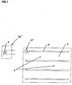
- Figure 1 and Figure 2a refer to a comparative example. For the sake of clarity, the figures are not drawn to scale and proportion.
- Figure 1 shows a schematic representation of a paper sheet 1, on which four transfer film strips 2 have been applied according to the prior art.
- the paper sheet 1 shown in the figure can be printed in subsequent steps, for example by means of screen, flexographic and intaglio printing processes, and finally cut into a large number of documents of value, in particular bank notes.
- the applied transfer film strips 2 come from a strip-like continuous film.
- the transfer film strips 2 were applied in that defined sections of the strip-shaped continuous film came into contact with a heated roller and were heated in this way. The heating led to a softening of the heat seal lacquer present on the surface of the defined film strip sections.
- the film strip sections were then glued to the paper sheet 1 by means of the melted heat-sealing lacquer.
- the transfer film strip 2 shown contains, among other things, a continuous or continuous UV embossing lacquer layer in its layer structure. Due to its brittleness, the UV varnish tends to form tinsel. As can be seen from the enlargement of the section "A" shown to the left of the paper sheet 1, there are unclean breaking edges and broken pieces or tinsel 3. The tinsel 3 arise when the UV lacquer is broken and impair the printability of the paper sheet 1 in the subsequent printing process.
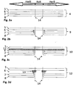
- FIG 2a shows a schematic representation of the layer structure of a strip-shaped continuous film 4 according to the prior art, which in the in the Figure 1 Comparative example shown was used.
- the endless film 4 contains a carrier film 5, in the present case a PET film.
- a UV embossing lacquer layer 6 Above the carrier film 5 there are a UV embossing lacquer layer 6, a primer layer 7 and a heat seal lacquer layer 8 in sequence. It is characteristic of the layer structure of the strip-like continuous film 4 according to the prior art that each of the UV lacquer layer, primer layer and heat seal lacquer layer is in shape there is a continuous or continuous layer.
- the adhesive 8 does not bond to the paper, so that the layers 6, 7 and 8 remain on the carrier film 5 within this section.
- the adhesive 8 is connected to the paper, so that the layers 6, 7 and 8 are applied to the paper within these sections and later from the carrier film 5 serving as a transfer film be replaced.
- the two in the Figures 2a to 2e The vertical straight lines 14 shown illustrate the predetermined breaking edges within the security element layer structure present on the carrier film 5.
- the UV lacquer 6 has to be broken at the points of the breaking edges, which is what in the Figure 1 shown bauble 3 results.
- FIG. 2b shows a schematic representation of the layer structure of a strip-shaped continuous film 9 according to a first embodiment of the invention.
- the UV embossing lacquer layer 6, the primer layer 7 and the heat-sealing lacquer layer 8 are each recessed in the continuous film 9. By cutting out the UV lacquer 6, the UV lacquer is prevented from breaking and thus the formation of tinsel.
- the continuous film 9 is produced by providing the carrier film 5 (for example a PET film) and printing the carrier film 5 with a UV lacquer layer 6 which has cutouts. Subsequently, a primer layer 7 and a heat seal lacquer layer 8 are printed successively, each of which has recesses.
- the primer layer 7 has larger dimensions than the UV varnish 6.
- the heat seal lacquer layer 8 in turn has larger dimensions than the primer layer 7.
- Figure 2c shows a schematic representation of the layer structure of a strip-shaped continuous film 10 according to a second embodiment of the invention.
- the endless film 10 has a continuous or continuous separating layer or release layer 11 which facilitates the detachment of the security element layer structure comprising the layers 6, 7 and 8 from the carrier film 5.
- the continuous film 10 is produced by providing the carrier film 5 and printing the entire area of the carrier film 5 with a release layer 11. This is followed by printing the release layer 11 with a UV lacquer layer 6 which has cutouts. Subsequently, a primer layer 7 and a heat seal lacquer layer 8 are printed successively, each of which has recesses.
- the primer layer 7 has larger dimensions than the UV varnish 6.
- the heat-sealing lacquer layer 8 in turn has larger dimensions than the primer layer 7.
- the release layer 11 prevents the primer layer 7 and the heat-sealing lacquer layer 8 from being connected to the carrier film 5 Sticking to the paper, ie after the heat sealing process, does not cause the paper to tear because the primer 7 has no direct contact with the film 5.
- the primer 7 and the heat seal lacquer 8 each have larger dimensions.
- This "lengthwise protrusion" of the primer 7 or the heat sealing lacquer 8 compared to the UV lacquer 6 is expediently in an area in which, due to the machine, there is still a sticking to the paper, that is to say a heat sealing.
- Figure 2d shows a schematic representation of the layer structure of a strip-shaped continuous film 12 according to a third embodiment of the invention.
- the exemplary embodiment shown is not formed continuously or continuously, but rather discontinuously, the separating layer or release layer 13.
- it is only necessary to ensure a good initial detachment (ie a good "initial release") of the security element layer structure comprising the UV varnish 6, the primer 7 and the heat seal lacquer 8 from the carrier film 5 and a bonding of the primer 7 to the carrier film 5 can be prevented.
- each security element has exactly one separating layer area on each of its two ends running perpendicular to the longitudinal direction of the strip-shaped continuous film.
- the separating layer arranged between two adjacent security elements has a cutout.
- Figure 2e shows a schematic representation of the layer structure of a strip-shaped continuous film 12 according to a fourth embodiment of the invention.
- the fourth embodiment is a modification of the third embodiment.
- the separating layer or release layer 13 is not continuous or continuous, but rather is formed discontinuously.
- the separate separating layer regions 13 are arranged such that each security element has exactly one separating layer region at each of its two ends running perpendicular to the longitudinal direction of the strip-shaped continuous film.
- the separating layer arranged between two adjacent security elements has no recess, that is to say the separating layer arranged between two adjacent security elements is formed continuously.
- the larger dimension of the separating layer compared to the third exemplary embodiment is advantageous because the separating layer is easier to produce by printing on the film.
- Figure 2f shows a schematic representation of the layer structure of a strip-shaped continuous film 12 according to a fifth embodiment of the invention.
- the fifth embodiment is a modification of the third embodiment ( Fig. 2d ).
- a separating layer or release layer 17 is not formed continuously or continuously, but discontinuously.
- the separate separating layer regions 17a, 17b of the separating layer 17 are arranged such that each security element 18 has exactly one separating layer region 17a, 17b at each of its two ends running perpendicular to the longitudinal direction of the strip-shaped continuous film.
- the strip-shaped continuous film 12 has two (UV) lacquer layers 6, 6a.
- the continuous film 12 is produced by providing the carrier film 5 and applying, for example, printing the carrier film 5 with a discontinuous separating layer or release layer 17. This is followed by the application of a UV lacquer layer 6 which has cutouts. The beginning of each recess in the UV lacquer layer 6 lies in the region of the release layer 17. A further UV lacquer layer 6a is then applied, which likewise has recesses. The recess in the further UV lacquer layer 6a is larger than the recesses in the UV lacquer layer 6, so that the (further) UV lacquer layer 6a does not envelop the UV lacquer layer 6. Furthermore, a primer layer 7 and a heat seal lacquer layer 8, which each have cutouts, are successively printed on.
- the primer layer 7 has larger dimensions than the UV lacquer layers 6 and 6a.
- the heat-sealing lacquer layer 8 in turn has larger dimensions than the primer layer 7.
- the discontinuous release layer 17 prevents the primer layer 7 and the heat-sealing lacquer layer 8 from being connected to the carrier film 5. In this way, the adhesive does not come into contact with the paper, ie after the heat-sealing process tearing of the paper because the primer 7 has no direct contact with the film 5.
- the primer 7 and the heat sealing lacquer 8 each have larger dimensions.
- This "lengthwise protrusion" of the primer 7 or the heat sealing lacquer 8 relative to the (UV) lacquers 6, 6a is expediently in an area in which, due to the machine, there is still a sticking to the paper, that is to say a heat sealing.
- Figure 2g shows a schematic representation of the layer structure of a strip-shaped continuous film 12 according to a sixth embodiment of the invention.
- the sixth embodiment is a modification of the fourth embodiment ( Fig. 2e ).
- a separating layer or release layer is not formed continuously or continuously, but discontinuously.
- the separate separating layer regions 19 are arranged such that each security element 18 has exactly one separating layer region 19 at each of its two ends running perpendicular to the longitudinal direction of the strip-shaped continuous film 12.
- the strip-like continuous film 12 has a (discontinuous) release layer 19 which (fills) the cutouts in the UV lacquer layer 6.
- the (discontinuous) release layer 19 has a layer thickness which is greater than the layer thickness of the UV lacquer layer 6. In other words, the (discontinuous) release layer 19 envelops the edge / edge regions of the UV lacquer layer 6. The (discontinuous) release layer or the respective separating layer region 19 thus overlaps the ends of the UV lacquer layer 6.
- the continuous film 12 is produced by providing the carrier film 5 and applying e.g. Printing the carrier film 5 with a UV lacquer layer 6 which has cutouts. This is followed by the application of a (discontinuous) release layer which fills the cutouts in the UV lacquer / UV lacquer layer 6 and overlaps the UV lacquer layer 6. Furthermore, a primer layer 7 and a heat seal lacquer layer 8, which each have cutouts, are successively printed on.
- the primer layer 7 can have larger dimensions than the UV lacquer layer 6. In other words, the primer layer 7 can protrude / protrude beyond the UV lacquer layer, i.e. protrude into the area of the recess of the UV lacquer layer 6.
- the primer layer 7 overlaps the release layer or the respective separating layer regions 19.
- the heat seal lacquer layer 8 in turn has larger dimensions than the primer layer 7 and thus overlaps the primer layer 7.
- the Primer 7 and the heat sealing lacquer 8 each have larger dimensions. This "lengthwise protrusion" of the primer 7 or the heat-sealing lacquer 8 with respect to the UV lacquer 6 is expediently in an area in which, due to the machine, it still sticks to the paper, i.e. to heat seal comes.
- Figure 3 shows a schematic representation of a sheet of paper 15 on which four transfer film strips 16 according to the above, in connection with Figure 2b described first embodiment have been applied.
- the applied transfer film strips 16 originate from a strip-like continuous film.
- the continuous film is composed of repetition units, each in the Figure 4 have shown structure.
- the carrier film 5 contains in each repetition unit a functional layer having a security feature, in the present case a UV embossing lacquer layer 6, which has a flat diffraction structure.
- a primer layer 7 is arranged above the embossing lacquer layer 6.
- the UV embossing lacquer layer 6 and the primer layer 7 are such that the UV embossing lacquer layer 6 is surrounded by the primer layer 7 in a U-shape.
- the primer layer 7 in turn is surrounded in a U-shape by the layer of heat seal adhesive 8.
- the (UV) lacquer layer or embossed lacquer layer or the UV lacquer can be constructed from several layers.
- the lacquer layers 6 and 6a can be produced from the same or different substances.
- U-shaped surrounding of a layer is to be understood in the present description in such a way that the layer in question is surrounded by another layer on three sides in the form of a rectangle.
- the rectangle may, but need not necessarily, have a regular geometry, i.e. have orthogonal interior angles.
- the advantageous effect of the present invention has been described in the preceding exemplary embodiments in connection with the UV embossing lacquer layer which tends to form tinsel.
- the invention is not limited to transfer elements with a UV embossing lacquer layer, but is suitable for all transfer elements that contain a functional layer that tends to form tinsel and has a security feature.
Claims (15)
- Feuille sans fin (9, 10, 12) en ruban ayant une face avant et une face arrière, cependant que la face avant comporte une pluralité d'éléments de sécurité qui, dans le sens longitudinal de la feuille sans fin (9, 10, 12) en ruban, sont agencés de manière espacée les uns des autres et sont respectivement réalisés en tant qu'élément de transfert détachable de la feuille sans fin (9, 10, 12) destiné à être placé sur un papier de sécurité ou sur un objet de valeur, et que chaque élément de sécurité comporte, vu depuis la face avant de la feuille sans fin (9, 10, 12), une couche fonctionnelle (6) de longueur F comportant une caractéristique de sécurité et une couche de colle thermoscellable (8) de longueur H agencée au-dessus de la couche fonctionnelle (6), cependant que les longueurs F et H se rapportent respectivement au sens longitudinal de la feuille sans fin (9, 10, 12) en ruban, cependant que les longueurs satisfont la relation F < H et que la couche fonctionnelle (6) comportant une caractéristique de sécurité et la couche de colle thermoscellable (8) sont telles que la couche fonctionnelle (6) est entourée en U par la couche de colle thermoscellable (8),
cependant que la couche fonctionnelle (6) comportant une caractéristique de sécurité est, vue depuis la face avant de la feuille sans fin (9, 10, 12), une couche de vernis de gaufrage (6) de longueur L qui présente une structure de diffraction plane et présente une couche d'apprêt (7) de longueur P agencée au-dessus de la couche de vernis de gaufrage (6), cependant que les longueurs L et P se rapportent respectivement au sens longitudinal de la feuille sans fin (9, 10, 12) en ruban et satisfont la relation L < P < H, et que la couche de vernis de gaufrage (6) et la couche d'apprêt (7) sont telles que la couche de vernis de gaufrage (6) est entourée en U par la couche d'apprêt (7) et la couche d'apprêt (7) est entourée en U par la couche de colle thermoscellable (8). - Feuille sans fin (10) en ruban selon la revendication 1, cependant que, entre la feuille sans fin (10) et la pluralité d'éléments de sécurité, une couche continue de séparation (11) est agencée.
- Feuille sans fin (12) en ruban selon la revendication 1, cependant que, entre la feuille sans fin (12) et la pluralité d'éléments de sécurité (18), une couche discontinue de séparation (13, 17) à zones distinctes de couche de séparation (17a, 17b) est agencée.
- Feuille sans fin (12) en ruban ayant une face avant et une face arrière, cependant que la face avant comporte une pluralité d'éléments de sécurité qui, dans le sens longitudinal de la feuille sans fin (12) en ruban, sont agencés de manière espacée les uns des autres et sont respectivement réalisés en tant qu'élément de transfert détachable de la feuille sans fin (12) destiné à être placé sur un papier de sécurité ou sur un objet de valeur, et que chaque élément de sécurité comporte, vu depuis la face avant de la feuille sans fin (12), une couche fonctionnelle (6) de longueur F comportant une caractéristique de sécurité et une couche de colle thermoscellable (8) de longueur H agencée au-dessus de la couche fonctionnelle (6), cependant que les longueurs F et H se rapportent respectivement au sens longitudinal de la feuille sans fin (12) en ruban, cependant que les longueurs satisfont la relation F < H et que la couche fonctionnelle (6) comportant une caractéristique de sécurité et la couche de colle thermoscellable (8) sont telles que la couche fonctionnelle (6) est entourée en U par la couche de colle thermoscellable (8),
cependant que, entre la feuille sans fin (12) et la pluralité d'éléments de sécurité (18), une couche discontinue de séparation (13, 17) à zones distinctes de couche de séparation (17a, 17b) est agencée, de telle façon que chaque élément de sécurité comporte, à chacune de ses deux extrémités perpendiculaires au sens longitudinal de la feuille sans fin (12) en ruban, exactement une zone de couche de séparation (17a, 17b), cependant que chaque zone de couche de séparation (17a, 17b) constitue avec la couche fonctionnelle (6) et la couche de colle thermoscellable (7) respectivement une surface limite commune. - Feuille sans fin (12) en ruban selon la revendication 4, cependant que la feuille sans fin (12) en ruban comporte une autre couche fonctionnelle agencée entre la couche fonctionnelle et la couche de colle thermoscellable (8), et que l'autre couche fonctionnelle présente, dans le sens longitudinal de la feuille sans fin (12) en ruban, la longueur WF, et que la relation F < WF < H est satisfaite.
- Feuille sans fin (12) en ruban selon la revendication 1, cependant que, entre la feuille sans fin (12) et la pluralité d'éléments de sécurité, une couche discontinue de séparation (13) à zones distinctes de couche de séparation (13) est agencée, de telle façon que chaque élément de sécurité comporte, à chacune de ses deux extrémités perpendiculaires au sens longitudinal de la feuille sans fin (12) en ruban, exactement une zone de couche de séparation (13), cependant que chaque zone de couche de séparation (13) constitue avec la couche de vernis de gaufrage (6), la couche d'apprêt (7) et la couche de colle thermoscellable (8) respectivement une surface limite commune.
- Feuille sans fin (12) en ruban selon la revendication 6, cependant que la feuille sans fin (12) en ruban comporte une autre couche fonctionnelle agencée entre la couche de vernis de gaufrage (6) et la couche d'apprêt (7), et que l'autre couche fonctionnelle présente, dans le sens longitudinal de la feuille sans fin (9, 12) en ruban, la longueur WP, et que la relation L < WP < P est satisfaite.
- Feuille sans fin (12) en ruban ayant une face avant et une face arrière, cependant que la face avant comporte une pluralité d'éléments de sécurité qui, dans le sens longitudinal de la feuille sans fin (12) en ruban, sont agencés de manière espacée les uns des autres et sont respectivement réalisés en tant qu'élément de transfert détachable de la feuille sans fin (12) destiné à être placé sur un papier de sécurité ou sur un objet de valeur, et que chaque élément de sécurité comporte, vu depuis la face avant de la feuille sans fin (12), une couche fonctionnelle (6) de longueur F comportant une caractéristique de sécurité et une couche de colle thermoscellable (8) de longueur H agencée au-dessus de la couche fonctionnelle (6), cependant que les longueurs F et H se rapportent respectivement au sens longitudinal de la feuille sans fin (12) en ruban, cependant que les longueurs satisfont la relation F < H, et cependant que la couche fonctionnelle (6) comportant une caractéristique de sécurité et la couche de colle thermoscellable (8) sont telles que la couche fonctionnelle (6) est entourée en U par la couche de colle thermoscellable (8),
cependant que, entre la feuille sans fin (12) et la pluralité d'éléments de sécurité, une couche discontinue de séparation (13) à zones distinctes de couche de séparation (13) est agencée, de telle façon que, à chacune de ses deux extrémités d'un élément de sécurité perpendiculaires au sens longitudinal de la feuille sans fin (12) en ruban, une zone de couche de séparation (13) est adjacente et exactement une zone de couche de séparation (13) est agencée entre deux éléments de sécurité. - Feuille sans fin (12) en ruban selon la revendication 8, cependant que la couche fonctionnelle (6) comportant une caractéristique de sécurité est, vue depuis la face avant de la feuille sans fin (12), une couche de vernis de gaufrage (6) de longueur L qui présente une structure de diffraction plane et présente une couche d'apprêt (7) de longueur P agencée au-dessus de la couche de vernis de gaufrage (6), cependant que les longueurs L et P se rapportent respectivement au sens longitudinal de la feuille sans fin (12) en ruban et satisfont la relation L < P < H, et que la couche de vernis de gaufrage et la couche d'apprêt (7) sont telles que la couche de vernis de gaufrage (6) est entourée en U par la couche d'apprêt (7) et la couche d'apprêt (7) est entourée en U par la couche de colle thermoscellable (8).
- Feuille sans fin (12) en ruban ayant une face avant et une face arrière, cependant que la face avant comporte une pluralité d'éléments de sécurité (18) qui, dans le sens longitudinal de la feuille sans fin (12) en ruban, sont agencés de manière espacée les uns des autres et sont respectivement réalisés en tant qu'élément de transfert détachable de la feuille sans fin (12) destiné à être placé sur un papier de sécurité ou sur un objet de valeur, et que chaque élément de sécurité (18) comporte, vu depuis la face avant de la feuille sans fin (12), une couche fonctionnelle (6) de longueur F comportant une caractéristique de sécurité et une couche de colle thermoscellable (8) de longueur H agencée au-dessus de la couche fonctionnelle (6), cependant que les longueurs F et H se rapportent respectivement au sens longitudinal de la feuille sans fin (12) en ruban, cependant que les longueurs satisfont la relation F < H, et cependant que la feuille sans fin comporte une feuille support (5) et que, entre la feuille support et la pluralité d'éléments de sécurité, une couche discontinue de séparation (13, 19) à zones distinctes de couche de séparation (19) est agencée, de telle façon que, à chacune de ses deux extrémités d'un élément de sécurité (18) perpendiculaires au sens longitudinal de la feuille sans fin (12) en ruban, une zone de couche de séparation (19) est adjacente et exactement une zone de couche de séparation (19) est agencée entre deux éléments de sécurité, cependant que la zone de couche de séparation (19) chevauche la couche fonctionnelle (6) des éléments de sécurité (18) adjacents.
- Feuille sans fin en ruban selon la revendication 10, cependant que la couche de colle thermoscellable (8) chevauche la zone de couche de séparation (19).
- Feuille sans fin en ruban selon la revendication 10 ou 11, cependant que la couche fonctionnelle (6) comportant une caractéristique de sécurité est, vue depuis la face avant de la feuille sans fin (12), une couche de vernis de gaufrage de longueur L qui présente une structure de diffraction plane et présente une couche d'apprêt (7) de longueur P agencée au-dessus de la couche de vernis de gaufrage, cependant que les longueurs L et P se rapportent respectivement au sens longitudinal de la feuille sans fin (12) en ruban et satisfont la relation L < P < H, et que la couche d'apprêt (7) chevauche la la zone de couche de séparation (19) et que la couche d'apprêt (7) est au moins partiellement entourée en U par la couche de colle thermoscellable (8).
- Feuille sans fin en ruban selon la revendication 10 ou 11, cependant que la feuille sans fin (12) comporte une autre couche fonctionnelle agencée entre la couche fonctionnelle (6) et la couche de colle thermoscellable (8), et que l'autre couche fonctionnelle présente, dans le sens longitudinal de la feuille sans fin en ruban, la longueur WF, et que la relation F < WF < H est satisfaite.
- Feuille sans fin en ruban selon la revendication 12, cependant que la feuille sans fin en ruban comporte une autre couche fonctionnelle agencée entre la couche de vernis de gaufrage et la couche d'apprêt (7), et que l'autre couche fonctionnelle présente, dans le sens longitudinal de la feuille sans fin en ruban, la longueur WP, et que la relation L < WP < P est satisfaite.
- Utilisation de la feuille sans fin en ruban selon une des revendications de 1 à 14 pour la sécurisation d'un papier de sécurité ou d'un objet de valeur.
Applications Claiming Priority (1)
| Application Number | Priority Date | Filing Date | Title |
|---|---|---|---|
| DE102013015689.0A DE102013015689A1 (de) | 2013-09-16 | 2013-09-16 | Streifenförmige Endlosfolie und deren Verwendung |
Publications (4)
| Publication Number | Publication Date |
|---|---|
| EP2848425A2 EP2848425A2 (fr) | 2015-03-18 |
| EP2848425A3 EP2848425A3 (fr) | 2015-04-22 |
| EP2848425B1 EP2848425B1 (fr) | 2016-11-09 |
| EP2848425B2 true EP2848425B2 (fr) | 2020-03-18 |
Family
ID=51589050
Family Applications (1)
| Application Number | Title | Priority Date | Filing Date |
|---|---|---|---|
| EP14003115.4A Active EP2848425B2 (fr) | 2013-09-16 | 2014-09-09 | Feuille sans fin en forme de bande et son utilisation |
Country Status (2)
| Country | Link |
|---|---|
| EP (1) | EP2848425B2 (fr) |
| DE (1) | DE102013015689A1 (fr) |
Families Citing this family (3)
| Publication number | Priority date | Publication date | Assignee | Title |
|---|---|---|---|---|
| DE102016009318A1 (de) | 2016-08-02 | 2018-02-08 | Giesecke+Devrient Currency Technology Gmbh | Verfahren und Transferfolie zum Übertragen von motivförmigen Sicherheitselementen auf ein Zielsubstrat |
| DE102017004999A1 (de) | 2017-05-24 | 2018-11-29 | Giesecke+Devrient Currency Technology Gmbh | Verfahren zur Herstellung von Mehrnutzenstreifen und deren Verwendung |
| DE102018001379A1 (de) | 2018-02-21 | 2019-08-22 | Giesecke+Devrient Currency Technology Gmbh | Transferträger |
Citations (8)
| Publication number | Priority date | Publication date | Assignee | Title |
|---|---|---|---|---|
| EP0537439A1 (fr) † | 1991-10-14 | 1993-04-21 | Landis & Gyr Technology Innovation AG | Elément de sécurité |
| EP0675006A1 (fr) † | 1994-03-31 | 1995-10-04 | Giesecke & Devrient GmbH | Stratifié avec des éléments individuels optiquement variables transférable sur des objets à protéger |
| DE4423291A1 (de) † | 1994-07-02 | 1996-01-11 | Kurz Leonhard Fa | Prägefolie, insbesondere Heissprägefolie mit Dekorations- oder Sicherungselementen |
| WO1996009174A1 (fr) † | 1994-09-22 | 1996-03-28 | Leonhard Kurz Gmbh & Co. | Film de transfert |
| EP0869408A1 (fr) † | 1996-09-19 | 1998-10-07 | Dai Nippon Printing Co., Ltd. | Stratifie avec hologramme en relief et etiquette permettant de preparer un tel stratifie avec hologramme en relief |
| EP1310381A2 (fr) † | 2001-11-09 | 2003-05-14 | Hueck Folien GmbH | Matériaux en bande avec une surface structurée, leur procédé de fabrication ainsi que leur utilisation |
| US6627286B1 (en) † | 1998-03-26 | 2003-09-30 | Leonhard Kurz Gmbh & Co. | Embossing foil, especially hot embossing foil |
| DE102010034793A1 (de) † | 2010-08-18 | 2012-02-23 | Hologram Industries Research Gmbh | Dokument mit Hologramm und Verfahren zu dessen Herstellung |
Family Cites Families (7)
| Publication number | Priority date | Publication date | Assignee | Title |
|---|---|---|---|---|
| ATE115916T1 (de) * | 1989-12-21 | 1995-01-15 | Landis & Gyr Tech Innovat | Vorrichtung zum aufkleben von marken aus einer prägefolie. |
| US5300169A (en) * | 1991-01-28 | 1994-04-05 | Dai Nippon Printing Co., Ltd. | Transfer foil having reflecting layer with fine dimple pattern recorded thereon |
| DE4404128A1 (de) * | 1993-02-19 | 1994-08-25 | Gao Ges Automation Org | Sicherheitsdokument und Verfahren zu seiner Herstellung |
| DE10132892A1 (de) * | 2001-07-06 | 2003-01-16 | Giesecke & Devrient Gmbh | Verfahren und Vorrichtung zum Herstellen eines Substrats mit Sicherheitselementen für Sicherheitsdokumente |
| DE102007005416B4 (de) * | 2007-01-30 | 2016-03-31 | Leonhard Kurz Gmbh & Co. Kg | Prägefolie und damit gebildeter Sicherheitsaufkleber |
| DE102008021944A1 (de) * | 2008-05-02 | 2009-11-05 | Giesecke & Devrient Gmbh | Verfahren und Vorrichtung zum Aufbringen streifenförmiger Endlosfolien auf eine Substratbahn |
| DE102009053978A1 (de) * | 2009-11-23 | 2011-06-01 | Leonhard Kurz Stiftung & Co. Kg | Mehrschichtkörper |
-
2013
- 2013-09-16 DE DE102013015689.0A patent/DE102013015689A1/de not_active Withdrawn
-
2014
- 2014-09-09 EP EP14003115.4A patent/EP2848425B2/fr active Active
Patent Citations (8)
| Publication number | Priority date | Publication date | Assignee | Title |
|---|---|---|---|---|
| EP0537439A1 (fr) † | 1991-10-14 | 1993-04-21 | Landis & Gyr Technology Innovation AG | Elément de sécurité |
| EP0675006A1 (fr) † | 1994-03-31 | 1995-10-04 | Giesecke & Devrient GmbH | Stratifié avec des éléments individuels optiquement variables transférable sur des objets à protéger |
| DE4423291A1 (de) † | 1994-07-02 | 1996-01-11 | Kurz Leonhard Fa | Prägefolie, insbesondere Heissprägefolie mit Dekorations- oder Sicherungselementen |
| WO1996009174A1 (fr) † | 1994-09-22 | 1996-03-28 | Leonhard Kurz Gmbh & Co. | Film de transfert |
| EP0869408A1 (fr) † | 1996-09-19 | 1998-10-07 | Dai Nippon Printing Co., Ltd. | Stratifie avec hologramme en relief et etiquette permettant de preparer un tel stratifie avec hologramme en relief |
| US6627286B1 (en) † | 1998-03-26 | 2003-09-30 | Leonhard Kurz Gmbh & Co. | Embossing foil, especially hot embossing foil |
| EP1310381A2 (fr) † | 2001-11-09 | 2003-05-14 | Hueck Folien GmbH | Matériaux en bande avec une surface structurée, leur procédé de fabrication ainsi que leur utilisation |
| DE102010034793A1 (de) † | 2010-08-18 | 2012-02-23 | Hologram Industries Research Gmbh | Dokument mit Hologramm und Verfahren zu dessen Herstellung |
Also Published As
| Publication number | Publication date |
|---|---|
| EP2848425B1 (fr) | 2016-11-09 |
| DE102013015689A1 (de) | 2015-03-19 |
| EP2848425A2 (fr) | 2015-03-18 |
| EP2848425A3 (fr) | 2015-04-22 |
Similar Documents
| Publication | Publication Date | Title |
|---|---|---|
| DE102007031059B4 (de) | Verfahren zur flächigen Kaschierung oder Laminierung von Druckbogen | |
| EP3505361B1 (fr) | Dispositif applicateur | |
| DE102007031060A1 (de) | Bogenrotationsdruckmaschine | |
| DE19907940A1 (de) | Verfahren zur Herstellung von mehrschichtigen Sicherheitsprodukten und ein nach dem Verfahren hergestelltes Sicherheitsprodukt | |
| EP2848425B2 (fr) | Feuille sans fin en forme de bande et son utilisation | |
| EP2981419A1 (fr) | Procédé servant à fabriquer un élément de sécurité pourvu d'une inscription négative | |
| DE102008053096A1 (de) | Verfahren und Vorrichtung zur Herstellung von Datenträgern und Datenträgerhalbzeugen, sowie Datenträger und Datenträgerhalbzeug | |
| EP1515857B1 (fr) | Composite multicouche pour element de securite | |
| DE102007031051A1 (de) | Kaschiertes Druckprodukt und Verfahren zur Herstellung desselben | |
| DE10151280B4 (de) | Verfahren zur Herstellung eines mehrschichtigen Sicherheitsdokuments | |
| EP2196322B1 (fr) | Elément de sécurité | |
| EP3521052A1 (fr) | Procédé de fabrication d'un matériau de transfert d'éléments de sécurité et matériau de transfert d'éléments de sécurité | |
| EP2011649A2 (fr) | Presse rotative d'impression pour feuilles | |
| CH697456B1 (de) | Bedruckbarer, blattförmiger Trà ger, Stapel solcher Trà ger und Verfahren zu ihrer Herstellung. | |
| EP3380335B1 (fr) | Système de gaufrage pour former des microstructures ou des nanostructures | |
| EP2266815A2 (fr) | Papier de sécurité pour la fabrication de documents de valeur | |
| EP3074235B1 (fr) | Élément de sécurité et procédé de sa fabrication | |
| EP1668606B1 (fr) | Element de securite et son procede de production | |
| DE102019131654B4 (de) | Verfahren zur Herstellung von Banknoten mit jeweils mindestens einer integrierten Schaltung | |
| DE102016010625A1 (de) | Verfahren zum maschinellen Stanzen von Nutzen sowie zugehörige Vorrichtung, Faltschachtel und Kodierungsverfahren | |
| EP3271191B1 (fr) | Élément de sécurité | |
| EP4214063A1 (fr) | Matériau de transfert d'éléments de sécurité permettant le transfert, dans un bon registre, d'éléments de sécurité à des documents de valeur | |
| EP1879162B1 (fr) | Produit pliant tout comme procédé destiné à la fabrication d'un produit estampillé avec une feuille en plastique | |
| EP1506853A2 (fr) | Procédé de fabrication d'un film de sécurité | |
| EP2949478A1 (fr) | Produit d'impression à code d'accès |
Legal Events
| Date | Code | Title | Description |
|---|---|---|---|
| PUAI | Public reference made under article 153(3) epc to a published international application that has entered the european phase |
Free format text: ORIGINAL CODE: 0009012 |
|
| 17P | Request for examination filed |
Effective date: 20140909 |
|
| AK | Designated contracting states |
Kind code of ref document: A2 Designated state(s): AL AT BE BG CH CY CZ DE DK EE ES FI FR GB GR HR HU IE IS IT LI LT LU LV MC MK MT NL NO PL PT RO RS SE SI SK SM TR |
|
| AX | Request for extension of the european patent |
Extension state: BA ME |
|
| PUAL | Search report despatched |
Free format text: ORIGINAL CODE: 0009013 |
|
| AK | Designated contracting states |
Kind code of ref document: A3 Designated state(s): AL AT BE BG CH CY CZ DE DK EE ES FI FR GB GR HR HU IE IS IT LI LT LU LV MC MK MT NL NO PL PT RO RS SE SI SK SM TR |
|
| AX | Request for extension of the european patent |
Extension state: BA ME |
|
| RIC1 | Information provided on ipc code assigned before grant |
Ipc: B42D 25/30 20140101ALI20150313BHEP Ipc: B42D 25/47 20140101ALI20150313BHEP Ipc: B42D 25/00 20140101ALI20150313BHEP Ipc: B44C 1/17 20060101AFI20150313BHEP |
|
| R17P | Request for examination filed (corrected) |
Effective date: 20151022 |
|
| RBV | Designated contracting states (corrected) |
Designated state(s): AL AT BE BG CH CY CZ DE DK EE ES FI FR GB GR HR HU IE IS IT LI LT LU LV MC MK MT NL NO PL PT RO RS SE SI SK SM TR |
|
| GRAP | Despatch of communication of intention to grant a patent |
Free format text: ORIGINAL CODE: EPIDOSNIGR1 |
|
| RIC1 | Information provided on ipc code assigned before grant |
Ipc: B42D 25/30 20140101ALI20160429BHEP Ipc: B42D 25/00 20140101ALI20160429BHEP Ipc: B44C 1/17 20060101AFI20160429BHEP Ipc: B42D 25/47 20140101ALI20160429BHEP |
|
| INTG | Intention to grant announced |
Effective date: 20160530 |
|
| GRAS | Grant fee paid |
Free format text: ORIGINAL CODE: EPIDOSNIGR3 |
|
| GRAA | (expected) grant |
Free format text: ORIGINAL CODE: 0009210 |
|
| AK | Designated contracting states |
Kind code of ref document: B1 Designated state(s): AL AT BE BG CH CY CZ DE DK EE ES FI FR GB GR HR HU IE IS IT LI LT LU LV MC MK MT NL NO PL PT RO RS SE SI SK SM TR |
|
| REG | Reference to a national code |
Ref country code: GB Ref legal event code: FG4D Free format text: NOT ENGLISH |
|
| REG | Reference to a national code |
Ref country code: AT Ref legal event code: REF Ref document number: 843545 Country of ref document: AT Kind code of ref document: T Effective date: 20161115 Ref country code: CH Ref legal event code: EP |
|
| REG | Reference to a national code |
Ref country code: IE Ref legal event code: FG4D Free format text: LANGUAGE OF EP DOCUMENT: GERMAN |
|
| REG | Reference to a national code |
Ref country code: DE Ref legal event code: R096 Ref document number: 502014001874 Country of ref document: DE |
|
| REG | Reference to a national code |
Ref country code: CH Ref legal event code: NV Representative=s name: PATENTANWAELTE SCHAAD, BALASS, MENZL AND PARTN, CH |
|
| PG25 | Lapsed in a contracting state [announced via postgrant information from national office to epo] |
Ref country code: LV Free format text: LAPSE BECAUSE OF FAILURE TO SUBMIT A TRANSLATION OF THE DESCRIPTION OR TO PAY THE FEE WITHIN THE PRESCRIBED TIME-LIMIT Effective date: 20161109 |
|
| REG | Reference to a national code |
Ref country code: LT Ref legal event code: MG4D |
|
| REG | Reference to a national code |
Ref country code: NL Ref legal event code: MP Effective date: 20161109 |
|
| PG25 | Lapsed in a contracting state [announced via postgrant information from national office to epo] |
Ref country code: GR Free format text: LAPSE BECAUSE OF FAILURE TO SUBMIT A TRANSLATION OF THE DESCRIPTION OR TO PAY THE FEE WITHIN THE PRESCRIBED TIME-LIMIT Effective date: 20170210 Ref country code: NO Free format text: LAPSE BECAUSE OF FAILURE TO SUBMIT A TRANSLATION OF THE DESCRIPTION OR TO PAY THE FEE WITHIN THE PRESCRIBED TIME-LIMIT Effective date: 20170209 Ref country code: NL Free format text: LAPSE BECAUSE OF FAILURE TO SUBMIT A TRANSLATION OF THE DESCRIPTION OR TO PAY THE FEE WITHIN THE PRESCRIBED TIME-LIMIT Effective date: 20161109 Ref country code: SE Free format text: LAPSE BECAUSE OF FAILURE TO SUBMIT A TRANSLATION OF THE DESCRIPTION OR TO PAY THE FEE WITHIN THE PRESCRIBED TIME-LIMIT Effective date: 20161109 Ref country code: LT Free format text: LAPSE BECAUSE OF FAILURE TO SUBMIT A TRANSLATION OF THE DESCRIPTION OR TO PAY THE FEE WITHIN THE PRESCRIBED TIME-LIMIT Effective date: 20161109 |
|
| PG25 | Lapsed in a contracting state [announced via postgrant information from national office to epo] |
Ref country code: IS Free format text: LAPSE BECAUSE OF FAILURE TO SUBMIT A TRANSLATION OF THE DESCRIPTION OR TO PAY THE FEE WITHIN THE PRESCRIBED TIME-LIMIT Effective date: 20170309 Ref country code: FI Free format text: LAPSE BECAUSE OF FAILURE TO SUBMIT A TRANSLATION OF THE DESCRIPTION OR TO PAY THE FEE WITHIN THE PRESCRIBED TIME-LIMIT Effective date: 20161109 Ref country code: PT Free format text: LAPSE BECAUSE OF FAILURE TO SUBMIT A TRANSLATION OF THE DESCRIPTION OR TO PAY THE FEE WITHIN THE PRESCRIBED TIME-LIMIT Effective date: 20170309 Ref country code: PL Free format text: LAPSE BECAUSE OF FAILURE TO SUBMIT A TRANSLATION OF THE DESCRIPTION OR TO PAY THE FEE WITHIN THE PRESCRIBED TIME-LIMIT Effective date: 20161109 Ref country code: RS Free format text: LAPSE BECAUSE OF FAILURE TO SUBMIT A TRANSLATION OF THE DESCRIPTION OR TO PAY THE FEE WITHIN THE PRESCRIBED TIME-LIMIT Effective date: 20161109 Ref country code: HR Free format text: LAPSE BECAUSE OF FAILURE TO SUBMIT A TRANSLATION OF THE DESCRIPTION OR TO PAY THE FEE WITHIN THE PRESCRIBED TIME-LIMIT Effective date: 20161109 Ref country code: ES Free format text: LAPSE BECAUSE OF FAILURE TO SUBMIT A TRANSLATION OF THE DESCRIPTION OR TO PAY THE FEE WITHIN THE PRESCRIBED TIME-LIMIT Effective date: 20161109 |
|
| PG25 | Lapsed in a contracting state [announced via postgrant information from national office to epo] |
Ref country code: EE Free format text: LAPSE BECAUSE OF FAILURE TO SUBMIT A TRANSLATION OF THE DESCRIPTION OR TO PAY THE FEE WITHIN THE PRESCRIBED TIME-LIMIT Effective date: 20161109 Ref country code: SK Free format text: LAPSE BECAUSE OF FAILURE TO SUBMIT A TRANSLATION OF THE DESCRIPTION OR TO PAY THE FEE WITHIN THE PRESCRIBED TIME-LIMIT Effective date: 20161109 Ref country code: DK Free format text: LAPSE BECAUSE OF FAILURE TO SUBMIT A TRANSLATION OF THE DESCRIPTION OR TO PAY THE FEE WITHIN THE PRESCRIBED TIME-LIMIT Effective date: 20161109 Ref country code: RO Free format text: LAPSE BECAUSE OF FAILURE TO SUBMIT A TRANSLATION OF THE DESCRIPTION OR TO PAY THE FEE WITHIN THE PRESCRIBED TIME-LIMIT Effective date: 20161109 Ref country code: CZ Free format text: LAPSE BECAUSE OF FAILURE TO SUBMIT A TRANSLATION OF THE DESCRIPTION OR TO PAY THE FEE WITHIN THE PRESCRIBED TIME-LIMIT Effective date: 20161109 |
|
| REG | Reference to a national code |
Ref country code: DE Ref legal event code: R026 Ref document number: 502014001874 Country of ref document: DE |
|
| REG | Reference to a national code |
Ref country code: DE Ref legal event code: R081 Ref document number: 502014001874 Country of ref document: DE Owner name: GIESECKE+DEVRIENT CURRENCY TECHNOLOGY GMBH, DE Free format text: FORMER OWNER: GIESECKE & DEVRIENT GMBH, 81677 MUENCHEN, DE |
|
| PLBI | Opposition filed |
Free format text: ORIGINAL CODE: 0009260 |
|
| RAP2 | Party data changed (patent owner data changed or rights of a patent transferred) |
Owner name: GIESECKE+DEVRIENT CURRENCY TECHNOLOGY GMBH |
|
| PG25 | Lapsed in a contracting state [announced via postgrant information from national office to epo] |
Ref country code: SM Free format text: LAPSE BECAUSE OF FAILURE TO SUBMIT A TRANSLATION OF THE DESCRIPTION OR TO PAY THE FEE WITHIN THE PRESCRIBED TIME-LIMIT Effective date: 20161109 Ref country code: BG Free format text: LAPSE BECAUSE OF FAILURE TO SUBMIT A TRANSLATION OF THE DESCRIPTION OR TO PAY THE FEE WITHIN THE PRESCRIBED TIME-LIMIT Effective date: 20170209 |
|
| PLAX | Notice of opposition and request to file observation + time limit sent |
Free format text: ORIGINAL CODE: EPIDOSNOBS2 |
|
| 26 | Opposition filed |
Opponent name: HUECK FOLIEN GESELLSCHAFT M.B.H. Effective date: 20170807 |
|
| REG | Reference to a national code |
Ref country code: FR Ref legal event code: PLFP Year of fee payment: 4 |
|
| PG25 | Lapsed in a contracting state [announced via postgrant information from national office to epo] |
Ref country code: SI Free format text: LAPSE BECAUSE OF FAILURE TO SUBMIT A TRANSLATION OF THE DESCRIPTION OR TO PAY THE FEE WITHIN THE PRESCRIBED TIME-LIMIT Effective date: 20161109 |
|
| REG | Reference to a national code |
Ref country code: CH Ref legal event code: PUE Owner name: GIESECKE+DEVRIENT CURRENCY TECHNOLOGY GMBH, DE Free format text: FORMER OWNER: GIESECKE AND DEVRIENT GMBH, DE |
|
| PLBB | Reply of patent proprietor to notice(s) of opposition received |
Free format text: ORIGINAL CODE: EPIDOSNOBS3 |
|
| REG | Reference to a national code |
Ref country code: GB Ref legal event code: 732E Free format text: REGISTERED BETWEEN 20180118 AND 20180124 |
|
| PG25 | Lapsed in a contracting state [announced via postgrant information from national office to epo] |
Ref country code: MC Free format text: LAPSE BECAUSE OF FAILURE TO SUBMIT A TRANSLATION OF THE DESCRIPTION OR TO PAY THE FEE WITHIN THE PRESCRIBED TIME-LIMIT Effective date: 20161109 |
|
| REG | Reference to a national code |
Ref country code: AT Ref legal event code: PC Ref document number: 843545 Country of ref document: AT Kind code of ref document: T Owner name: GIESECKE+DEVRIENT CURRENCY TECHNOLOGY GMBH, DE Effective date: 20180427 |
|
| REG | Reference to a national code |
Ref country code: IE Ref legal event code: MM4A |
|
| REG | Reference to a national code |
Ref country code: BE Ref legal event code: MM Effective date: 20170930 |
|
| PG25 | Lapsed in a contracting state [announced via postgrant information from national office to epo] |
Ref country code: LU Free format text: LAPSE BECAUSE OF NON-PAYMENT OF DUE FEES Effective date: 20170909 |
|
| REG | Reference to a national code |
Ref country code: FR Ref legal event code: TP Owner name: GIESECKE+DEVRIENT CURRENCY TECHNOLOGY GMBH, DE Effective date: 20180530 |
|
| PG25 | Lapsed in a contracting state [announced via postgrant information from national office to epo] |
Ref country code: IE Free format text: LAPSE BECAUSE OF NON-PAYMENT OF DUE FEES Effective date: 20170909 |
|
| PG25 | Lapsed in a contracting state [announced via postgrant information from national office to epo] |
Ref country code: BE Free format text: LAPSE BECAUSE OF NON-PAYMENT OF DUE FEES Effective date: 20170930 |
|
| REG | Reference to a national code |
Ref country code: FR Ref legal event code: PLFP Year of fee payment: 5 |
|
| PG25 | Lapsed in a contracting state [announced via postgrant information from national office to epo] |
Ref country code: MT Free format text: LAPSE BECAUSE OF FAILURE TO SUBMIT A TRANSLATION OF THE DESCRIPTION OR TO PAY THE FEE WITHIN THE PRESCRIBED TIME-LIMIT Effective date: 20161109 |
|
| PG25 | Lapsed in a contracting state [announced via postgrant information from national office to epo] |
Ref country code: HU Free format text: LAPSE BECAUSE OF FAILURE TO SUBMIT A TRANSLATION OF THE DESCRIPTION OR TO PAY THE FEE WITHIN THE PRESCRIBED TIME-LIMIT; INVALID AB INITIO Effective date: 20140909 |
|
| APBM | Appeal reference recorded |
Free format text: ORIGINAL CODE: EPIDOSNREFNO |
|
| APBP | Date of receipt of notice of appeal recorded |
Free format text: ORIGINAL CODE: EPIDOSNNOA2O |
|
| APAH | Appeal reference modified |
Free format text: ORIGINAL CODE: EPIDOSCREFNO |
|
| APBU | Appeal procedure closed |
Free format text: ORIGINAL CODE: EPIDOSNNOA9O |
|
| PG25 | Lapsed in a contracting state [announced via postgrant information from national office to epo] |
Ref country code: CY Free format text: LAPSE BECAUSE OF FAILURE TO SUBMIT A TRANSLATION OF THE DESCRIPTION OR TO PAY THE FEE WITHIN THE PRESCRIBED TIME-LIMIT Effective date: 20161109 |
|
| PG25 | Lapsed in a contracting state [announced via postgrant information from national office to epo] |
Ref country code: MK Free format text: LAPSE BECAUSE OF FAILURE TO SUBMIT A TRANSLATION OF THE DESCRIPTION OR TO PAY THE FEE WITHIN THE PRESCRIBED TIME-LIMIT Effective date: 20161109 |
|
| PUAH | Patent maintained in amended form |
Free format text: ORIGINAL CODE: 0009272 |
|
| STAA | Information on the status of an ep patent application or granted ep patent |
Free format text: STATUS: PATENT MAINTAINED AS AMENDED |
|
| REG | Reference to a national code |
Ref country code: CH Ref legal event code: AELC |
|
| 27A | Patent maintained in amended form |
Effective date: 20200318 |
|
| AK | Designated contracting states |
Kind code of ref document: B2 Designated state(s): AL AT BE BG CH CY CZ DE DK EE ES FI FR GB GR HR HU IE IS IT LI LT LU LV MC MK MT NL NO PL PT RO RS SE SI SK SM TR |
|
| REG | Reference to a national code |
Ref country code: DE Ref legal event code: R102 Ref document number: 502014001874 Country of ref document: DE |
|
| PG25 | Lapsed in a contracting state [announced via postgrant information from national office to epo] |
Ref country code: TR Free format text: LAPSE BECAUSE OF FAILURE TO SUBMIT A TRANSLATION OF THE DESCRIPTION OR TO PAY THE FEE WITHIN THE PRESCRIBED TIME-LIMIT Effective date: 20161109 |
|
| PG25 | Lapsed in a contracting state [announced via postgrant information from national office to epo] |
Ref country code: AL Free format text: LAPSE BECAUSE OF FAILURE TO SUBMIT A TRANSLATION OF THE DESCRIPTION OR TO PAY THE FEE WITHIN THE PRESCRIBED TIME-LIMIT Effective date: 20161109 |
|
| P01 | Opt-out of the competence of the unified patent court (upc) registered |
Effective date: 20230520 |
|
| PGFP | Annual fee paid to national office [announced via postgrant information from national office to epo] |
Ref country code: GB Payment date: 20230921 Year of fee payment: 10 Ref country code: AT Payment date: 20230915 Year of fee payment: 10 |
|
| PGFP | Annual fee paid to national office [announced via postgrant information from national office to epo] |
Ref country code: FR Payment date: 20230919 Year of fee payment: 10 Ref country code: DE Payment date: 20230930 Year of fee payment: 10 |
|
| PGFP | Annual fee paid to national office [announced via postgrant information from national office to epo] |
Ref country code: IT Payment date: 20230929 Year of fee payment: 10 Ref country code: CH Payment date: 20231001 Year of fee payment: 10 |