EP2848178B1 - Mop with an automatic tiltable head for surface cleaning - Google Patents
Mop with an automatic tiltable head for surface cleaning Download PDFInfo
- Publication number
- EP2848178B1 EP2848178B1 EP14184688.1A EP14184688A EP2848178B1 EP 2848178 B1 EP2848178 B1 EP 2848178B1 EP 14184688 A EP14184688 A EP 14184688A EP 2848178 B1 EP2848178 B1 EP 2848178B1
- Authority
- EP
- European Patent Office
- Prior art keywords
- base
- head
- wings
- handle
- cleaning head
- Prior art date
- Legal status (The legal status is an assumption and is not a legal conclusion. Google has not performed a legal analysis and makes no representation as to the accuracy of the status listed.)
- Active
Links
- 238000004140 cleaning Methods 0.000 title claims description 78
- 230000000903 blocking effect Effects 0.000 claims description 11
- 230000001960 triggered effect Effects 0.000 claims description 7
- 230000002452 interceptive effect Effects 0.000 claims description 3
- 244000007853 Sarothamnus scoparius Species 0.000 description 26
- 238000009987 spinning Methods 0.000 description 8
- 230000003100 immobilizing effect Effects 0.000 description 4
- 238000005119 centrifugation Methods 0.000 description 3
- 239000007788 liquid Substances 0.000 description 3
- 230000002829 reductive effect Effects 0.000 description 3
- 238000003860 storage Methods 0.000 description 3
- 238000001035 drying Methods 0.000 description 2
- 230000000694 effects Effects 0.000 description 2
- 238000003780 insertion Methods 0.000 description 2
- 230000037431 insertion Effects 0.000 description 2
- 238000005406 washing Methods 0.000 description 2
- XLYOFNOQVPJJNP-UHFFFAOYSA-N water Substances O XLYOFNOQVPJJNP-UHFFFAOYSA-N 0.000 description 2
- 239000000654 additive Substances 0.000 description 1
- 230000000996 additive effect Effects 0.000 description 1
- 230000000295 complement effect Effects 0.000 description 1
- 230000006835 compression Effects 0.000 description 1
- 238000007906 compression Methods 0.000 description 1
- 239000003599 detergent Substances 0.000 description 1
- 239000000428 dust Substances 0.000 description 1
- 230000003670 easy-to-clean Effects 0.000 description 1
- 239000004744 fabric Substances 0.000 description 1
- 239000012530 fluid Substances 0.000 description 1
- 239000011521 glass Substances 0.000 description 1
- 238000005304 joining Methods 0.000 description 1
- 230000000670 limiting effect Effects 0.000 description 1
- 238000000034 method Methods 0.000 description 1
- 239000000203 mixture Substances 0.000 description 1
- 230000000149 penetrating effect Effects 0.000 description 1
- 230000003252 repetitive effect Effects 0.000 description 1
- 230000000717 retained effect Effects 0.000 description 1
- 238000010079 rubber tapping Methods 0.000 description 1
- 238000007790 scraping Methods 0.000 description 1
Images


Classifications
-
- A—HUMAN NECESSITIES
- A47—FURNITURE; DOMESTIC ARTICLES OR APPLIANCES; COFFEE MILLS; SPICE MILLS; SUCTION CLEANERS IN GENERAL
- A47L—DOMESTIC WASHING OR CLEANING; SUCTION CLEANERS IN GENERAL
- A47L13/00—Implements for cleaning floors, carpets, furniture, walls, or wall coverings
- A47L13/10—Scrubbing; Scouring; Cleaning; Polishing
- A47L13/20—Mops
- A47L13/24—Frames for mops; Mop heads
- A47L13/254—Plate frames
- A47L13/258—Plate frames of adjustable or foldable type
-
- A—HUMAN NECESSITIES
- A47—FURNITURE; DOMESTIC ARTICLES OR APPLIANCES; COFFEE MILLS; SPICE MILLS; SUCTION CLEANERS IN GENERAL
- A47L—DOMESTIC WASHING OR CLEANING; SUCTION CLEANERS IN GENERAL
- A47L13/00—Implements for cleaning floors, carpets, furniture, walls, or wall coverings
- A47L13/10—Scrubbing; Scouring; Cleaning; Polishing
- A47L13/20—Mops
- A47L13/24—Frames for mops; Mop heads
- A47L13/254—Plate frames
- A47L13/256—Plate frames for mops made of cloth
-
- A—HUMAN NECESSITIES
- A47—FURNITURE; DOMESTIC ARTICLES OR APPLIANCES; COFFEE MILLS; SPICE MILLS; SUCTION CLEANERS IN GENERAL
- A47L—DOMESTIC WASHING OR CLEANING; SUCTION CLEANERS IN GENERAL
- A47L13/00—Implements for cleaning floors, carpets, furniture, walls, or wall coverings
- A47L13/10—Scrubbing; Scouring; Cleaning; Polishing
- A47L13/50—Auxiliary implements
- A47L13/58—Wringers for scouring pads, mops, or the like, combined with buckets
Definitions
- the present disclosure relates to a cleaning head and an easy-to-use, spin-drying surface cleaning brush and a bucket adapted for spinning.
- Such a broom equipped for example with a washing head or dedusting, makes it possible to clean the floors in a convenient manner while ensuring an easy and effective spinning of its cleaning head.
- articulated brushes equipped with a cleaning head comprising for example a sponge or mopping pad.
- a cleaning head comprising for example a sponge or mopping pad.
- Such brushes are often more efficient and more manoeuvrable than mops also known.
- the generally rectangular shape of these cleaning heads ensures easy cleaning of the corners of parts while their articulation makes it easy to clean under furniture.
- the cleaning pad has a rigid support, which allows to exert a greater force on the work surface and thus to remove more easily dirt.
- wiper devices comprise squeegees or rollers arranged at the top of the bucket; however, these devices are difficult to use because of the instability of the bucket, the latter may indeed move or overturn during the spin.
- the present disclosure relates to a brush cleaning head, comprising a fastening portion adapted to attach the cleaning head to a brush handle, a base mounted at the lower end of the fastening portion via a hinge. , and at least two wings extending from opposite lateral edges of the base, each wing being pivotable relative to the base between a rest position, in which it extends substantially in the extension of the base, and a raised position, so that the cleaning head can be operated between a working position, substantially rectilinear, in which the wings are in their rest positions, and a folding position, substantially U-shaped, in which the wings are in their raised positions.
- a broom equipped with this head has all the advantages already mentioned of this type of broom: it benefits in particular from a very good maneuverability, including in the corners of rooms and under furniture, and of great efficiency.
- this broom in addition, thanks to this collapsible U-shaped head, this broom, once folded, has a small footprint. It is thus easier to plunge it into a bucket to impregnate its cleaning head with a washing solution; the size of the bucket can also be reduced, which is significant for its storage. Moreover, thanks to its folding wings, the broom is also easier to store. It takes first place on the ground reduced and enjoys a stable standing, which is not the case for brooms whose head is up against the handle.
- this U-folded position makes it easy to wring the cleaning head into a bucket with a spin basket in the same manner as a conventional mop.
- a rectangular rather than circular basket can be used.
- Such spin in a spin basket enabled by the U-shape of this broom, is very easy and very effective: just exert a vertical pressure on the handle to compress the cleaning head against the basket.
- the bucket's position is stable during spinning, which improves its efficiency and reduces the risk of bucket spilling.
- the head includes at least one biasing device configured to bias a wing toward its home position. In this way, the cleaning head is automatically returned to the working position after the spin without the user has to handle the head, which is hygienic and more comfortable.
- this return device comprises a hinge spring.
- At least one of one of the wings and the base comprises at least two parts able to move relative to each other against elastic return means for reduce the length of said element, measured perpendicularly to the pivot axes of the wings relative to the base.
- at least one of the wings comprises an inner lateral portion through which said wing is connected to the base, and an outer lateral portion which is able to move towards the inner lateral portion against elastic return means .
- the two wings are configured in this way.
- the length of at least one of the sections of the head can temporarily decrease to avoid an overall increase in the length of the head and thus allow the passage of this head to its U-fold position without excessive stretching of the seal which can then be fixed on this head.
- the elastic return means return the section concerned to its normal length.
- the head includes at least one locking device configured to maintain a wing in its raised position when brought into that position.
- This blocking device locks the U-shaped configuration of the head at the time of spinning or storage, increasing user comfort. In particular, this prevents the head from opening in the bucket, during spinning, or in a closet, which could make it difficult to extract and handle.
- one of the base and said wing comprises at least one locking aperture
- the other of said elements among the base and said wing comprises a lug biased outwardly by means of reminder and configured to engage in said locking aperture when the wing is in its raised position.
- these return means comprise a spring.
- said locking aperture is provided on the dorsal face of the base, and said wing comprises said lug, the latter being biased toward the base by means of said biasing means.
- ventral and diorsal are defined relative to the base of the cleaning head, its ventral side being intended to be in contact with the work surface.
- the side edges of the base have a guide surface accompanying said lug to the locking aperture when the wing is moved to its raised position.
- the head further comprises at least one unlocking device configured, when triggered, for disabling said blocking device.
- the unblocking device is configured to be triggered in response to a predetermined movement of the attachment portion relative to the base.
- the user can unlock the wing and return the cleaning head to its working position by manipulating only the handle and not the cleaning head itself, which is hygienic and more comfortable.
- the unblocking device is configured to be triggered when the attachment portion is inclined at a predetermined angle to the base.
- the unblocking device is configured to be triggered when the securing portion is pushed a predetermined distance from the base.
- the base includes a release lever having a repetitive portion configured to penetrate into said locking aperture and urging the stub to break engagement with the locking aperture
- the release lever further has a bearing surface configured to cooperate with an integral member of the attachment portion, the lever pushing portion being moved toward the locking aperture when said member secured to the attachment portion moves the bearing surface towards the ventral side of the cleaning head.
- said integral member of the attachment portion is a cam portion of the hinge.
- the head includes an immobilizer configured to lock at least one degree of freedom of the base relative to the attachment portion when the base is not supported against a work surface. This is advantageous for immobilizing the cleaning head in a given position relative to the handle during the spinning for example. In this way, it is easier to maneuver the broom in a bucket or spin device. In addition, the risk that the unlocking device is triggered unintentionally is reduced. It should be pointed out, however, that if such an immobilizing device is particularly advantageous in combination with the blocking device mentioned above, it goes without saying that it could quite well equip a cleaning head devoid of such a device. blocking or even devoid of movable wings: indeed, this immobilization function is intrinsically advantageous regardless of the type of cleaning head used to facilitate for example the spin as mentioned above.
- the hinge is configured to give the base two degrees of freedom of rotation relative to the attachment portion: a first degree of freedom in front-to-back rotation and a second degree of freedom in rotation right left.
- the hinge comprises a first fork secured to the fixing portion, a second fork secured to the base and an intermediate piece comprising a first hinge axis with the first fork and a second hinge pin with the second fork.
- the immobilizer is configured to immobilize the base in a plane substantially perpendicular to the attachment portion.
- the base comprises at least one immobilization tab, mounted movably in a recess of the ventral face of the base between a projecting position in which the tab projects under the ventral face of the base and a flush position. wherein the tab is flush with the ventral face of the base, biasing means biasing the immobilizing tab towards its projecting position.
- said tab cooperates with a first end of a rod configured to slide within a passage of the hinge, said rod interfering with at least a portion of the hinge when the lug is in its projecting position.
- the rod when the blade is pressed against a work surface, the rod does not interfere with the joint and the cleaning head can be articulated freely for cleaning; on the other hand, when the cleaning head is raised from the ground, for example at the time of its passage in a bucket or of its spinning, at least one degree of freedom of the cleaning head is blocked.
- a second end of the rod cooperates with a protruding portion of a bushing housed in the attachment portion, said projecting portion impeding at least a portion of the hinge when the tab is in its projecting position. This makes it possible to block another degree of freedom of the cleaning head.
- a spring is mounted between the socket and a seat of the attachment portion.
- At least one wing comprises at least one cleat forming under the ventral face of the base when said wing is raised. This makes it possible to keep the immobilizer active, or partially active, even when the blade is placed on a surface, for example a drying basket or a storage surface. surface that can not fully press the locking tab due to the cleat.
- the head further comprises an impregnable liner capable of retaining a liquid, which liner is removably attached to the ventral side of the cleaning head.
- Such a liner may in particular comprise antistatic properties and be impregnated with a cleaning additive such as a wax.
- the liner is attached using at least one elastic band.
- the liner is secured with Velcro strips.
- the base is of substantially rectangular shape, preferably square. This facilitates the cooperation of the broom with a spin basket.
- the present disclosure further relates to a surface cleaning brush comprising a handle and a cleaning head, according to any one of the preceding embodiments, mounted at the lower end of the handle via its fixing portion.
- the wiper includes a longitudinal rotation drive device of the cleaning head about the longitudinal axis of the handle.
- This device makes it possible to spin the cleaning head by centrifugation, for example in a bucket provided with a rotary drilled basket.
- centrifugation method is more efficient and requires less effort than the compression wringing method.
- the rotational driving device is a buzzing router type mechanism. Such a mechanism is particularly easy to use.
- the rotational drive is provided in the brush handle.
- the rotational drive comprises a rotatable ring configured to cooperate with at least one helical track of a sleeve sliding around the handle.
- the rotational drive further comprises a clutch device configured to secure the rotating ring to a lower handle portion when the sleeve is moved in a first direction along the handle, and to disengage. the rotating ring of the lower part of the handle when the sleeve is moved in the opposite direction. This allows driving the cleaning head always in the same direction of rotation by making movements back and forth with the sleeve.
- the present disclosure also relates to a bucket, adapted to cooperate with a surface cleaning broom, comprising a reservoir capable of containing a liquid of the cleaning solution type, and a wiper device provided above the tank and comprising a pierced basket.
- a cleaning head of a broom the basket having a substantially prism or truncated pyramid geometry configured to receive a cleaning head having a substantially rectangular base and wings extending transversely from edges of the based.
- a bucket is therefore particularly suitable for a cleaning head and a broom according to the present disclosure.
- the wiper device is rotatably mounted to allow spinning of a cleaning head by centrifugation.
- the bucket comprises at least two inclined planes provided vis-à-vis at least at the inlet of the reservoir, configured to cooperate with the wings of a cleaning head. These inclined planes automatically fold the wings of the cleaning head in their raised positions when inserted into the bucket.
- At least one of said inclined planes has a rough surface, provided for example with ribs. The latter makes it possible to remove some of the dirt present on the surface of the cleaning head.
- the bottom of the basket has support ribs. These allow better cooperation between the basket and a cleaning head.
- these ribs extend from the center of the basket bottom and stop before the side walls of the basket.
- the present disclosure finally relates to an assembly comprising a broom and a bucket according to the present disclosure.
- the pierced basket is configured to cooperate with the cleaning head at the base and end of the wings only.
- the side walls of the pierced basket extend higher than the wings when the cleaning head is inserted into the pierced basket.
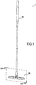
- FIG 1 represents in perspective an embodiment of a broom 1 according to the present disclosure.
- This blade 1 comprises a handle 10 and a cleaning head 50 mounted at the lower end of the handle 10 via a fixing portion 51.
- This cleaning head 50 has a substantially rectangular shape.
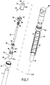
- FIG 2 to 6 illustrate more specifically the cleaning head 50. It mainly comprises the fixing portion 51, a base 60, two wings 70a and 70b, and a hinge 80.
- a cleaning cloth 90 is removably attached to the ventral side 60b of the head 50: it comprises for this elastic bands 91 which are threaded around the ends 79a of the wings 70a, 70b.
- the fixing portion 51 comprises a tapping 52 enabling the threaded lower end 11a of the handle 10 to be mounted.
- the base 60 is articulated with the fixing portion 51, and therefore with the handle 10, using the hinge 80.
- This hinge 80 provided at the geometric center of the base 60, that is to say, at the intersection of the median lines of its dorsal surface 60a, comprises two perpendicular axes of rotation A and B.
- the first axis of rotation A called the inclination axis, is collinear with the direction of more large extension of the head 50: it is made by journals 81 of the hinge 80 engaging in the bearings 61a of a fork 61 of the base 60.
- the second axis of rotation B perpendicular to the axis A, is defined by flares 82 engaging in bearings 83 of the hinge 80 and 53a of a fork 53 of the fastening portion 51.
- the two wings 70a, 70b are pivotable relative to the base by being articulated along the lateral ends of the base 60 by means of pivot axes represented by shafts 71: the wings 70a, 70b can thus extend the along the base 60 in a rest position, as shown in FIG. FIG 3 in particular, or be raised transversely to the base 60, on its dorsal side 60a, in a raised position as shown in FIG. FIG 4A especially.
- Hinge springs 72 are arranged around these shafts 71 so as to return the wings 70a, 70b towards their rest positions.
- the wings 70a, 70b each further comprise a cavity 73 opening on the edge of the wing 70a, 70b opposite the base 60.
- a cavity 73 is mounted in this cavity 73 a sleeve 74 provided with a lug 74a .
- a spring 75 is mounted between this socket and the opposite wall of the cavity 73 to push the lug 74a out of the cavity 73 towards the base 60.
- At least one of the wings 70a, 70b (in this case, it is the two wings) comprises an outer lateral portion forming its end 79a opposite to the pivot shaft 71 and an internal lateral portion 79b , which cooperates with the shaft 71 to connect the wing to the base 60.
- Springs 75 ' are disposed between the outer and inner side portions, or between the outer side portion and the base.
- the outer lateral portion 79a is normally maintained at a slight distance from the inner lateral portion 79b, but it can be brought closer when the head is folded to allow this fold without the risk of tearing the trim which is then attached to the head. From the point of view of keeping the external lateral portions at a distance from the internal lateral portions, the return effects of the springs 75 and 75 'can be combined.
- the outer lateral portion 79a includes extensions 79'a which are inserted into grooves guide 79'b that has the internal lateral portion 79b.
- the springs 75 ' are held in grooves 79''which the extensions 79'a have, the structure could be reversed, with the guide grooves in the outer side portions and the extensions on the inner side portions.
- the base 60 includes locking apertures 62 passing through the dorsal wall 60a of the base 60 in a position such that the lugs 74a of the wings 70a, 70b are capable of penetrating into these locking openings 62 when the wings 70a , 70b are in their raised positions.
- the lateral edges of the base 60 are rounded so that the lugs 74a can slide easily along these edges to the locking apertures 62.
- the base 60 further comprises unlocking levers 63; each lever 63 is articulated around a median axis 63a and comprises at its ends, in opposite manner, an unlocking portion 63b and a bearing surface 63c.
- the bearing surface 63c extends in contact with a cam portion 84 of the hinge 80 comprising a flat portion 84a and front and rear corners 84b.
- the base 60 further comprises locking tabs 64.
- Each tab 64 is articulated within a recess 65 of the base 60 about an axis 64a between a flush position, as shown in FIG. FIG 5 , in which the tab 64 is flush with the ventral surface 60b of the base 60, and a projecting position, as shown in FIG. FIG 6 in which it protrudes below the ventral surface 60b.
- Each tab 64 has at its distal end a bearing portion 64b.
- the fixing portion 51 comprises a cavity 54 opening at the lower edge of the fixing portion 51 vis-à-vis the hinge 80.
- a sleeve 55 provided with a finger 55a.
- a spring 56 is mounted between this bushing 55 and the opposite wall of the cavity 54 so as to push the finger 55a out of the cavity 54 in the direction of the hinge 80.
- the hinge 80 comprises a longitudinal through passage 85 in which slides a rod 86.
- This rod 86 has a foot 87 whose rounded bottom surface 87a cooperates with the bearing portions 64b of the tabs 64; it has at its upper end an apex 88 cooperating with the finger 55a of the sleeve 55 of the fixing portion 51.
- the base 60 further comprises inclined abutment surfaces 66 extending on either side of the foot 87 of the rod 86.
- the interface between the apex 88 of the rod 86 and the finger 55a of the bushing 55 is located at the top of the passage 85 of the hinge 80: consequently, the rotation of the handle 10 around the axis B of the joint 80 is free (this is also visible on the FIG 3 ).
- the handle 10 can also be inclined around the inclination axis A because, as is better visible on the magnifying glass of the FIG 5 the side surfaces 87b of the foot 87 of the rod 86 are not impeded by the abutment surfaces 66 of the base 60.
- the immobilization lugs 64 are no longer constrained and can rejoin their projecting positions: the spring 56 thus pushes the bushing 55, which pushes the rod 86, which pushes the legs 64.
- the foot 87 of the rod 86 is lower and therefore closer to the base 60 so that its flank surfaces 87b abut against the abutment surfaces 65 of the base 60 when the it attempts to maneuver the handle 10 of the blade 1 around the axis of inclination A. Thanks to the slope of the abutment surfaces 65, the rotation around the inclination axis A is not completely prevented: it requires however, a greater inclination force to overcome the friction forces at the abutment surfaces 65 as well as the biasing force of the spring 56. However, this is sufficient to prevent the head 50 from tilting under its own weight when raised above the ground S.
- the inner edges of the wings 70a, 70b form, when they are in the raised position, tabs 76 protruding under the ventral surface 60b of the base 60.
- the immobilization tabs 64 are only partially supported by said surface up to the level of the cleats 76.
- the foot 87 of the rod 86 is slightly raised, its flank surfaces 87b meeting the abutment surfaces 65 a little higher, near their upper end: this thus facilitates a little the inclination of the handle 10 around the axis of inclination A without, however, allow it completely without effort.
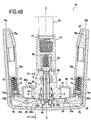
- the handle 10 of the blade 1 and its drive system in longitudinal rotation of the head 50 will now be described in more detail with reference to the FIG 7 and 8 .
- the handle 10 comprises a lower tube 11 and an upper tube 12.
- a lower interface piece 21 is mounted at the upper end of the lower tube 11: it comprises a fixing portion 21a, mounted in force in the lower tube 11, a portion toothed 21b and a tubular portion 21c; a longitudinal cylindrical passage 21d crosses almost to its lower end.
- An upper interface piece 22 is mounted at the lower end of the upper tube 12: it comprises a fixing portion 22a, mounted in force in the upper tube 12, a recess 22b and a longitudinal cylindrical passage 22c which passes through it in full.
- the tubular portion 21c of the lower interface piece 21 is in abutment against the bottom of the recess 22b of the upper interface piece 22.
- Two washers 35 and 36 serving respectively as a sliding washer (with a low coefficient of friction) and an anti-friction washer. noise, can be arranged around the tubular portion 21c, inside the recess 22b.
- a rod 23 is inserted into the passages 21d and 22c of the interface parts 21 and 22 and fixed by means of pins 24 passing through the interface parts 21, 22. With this rod 23, the lower tubes 11 and upper 12 of the handle 10 are solidarisés.
- a clutch ring 30 is integral with the toothed portion 21b of the lower interface piece 21: it comprises a plurality of clutch teeth 21 each having a plane inclined on one side and a steep wall on the other side.
- a rotating ring 32 is disposed around the tubular portion 21c between the clutch ring 30 and the washers 35 and 36: it can slide along and rotate around the tubular portion 21c. It comprises drive teeth 33 and clutch teeth 34 having a profile complementary to the clutch teeth 31 of the clutch ring 30.
- a spring 39 disposed between an inner shoulder 37 of the rotary ring 32 and a shoulder 38 of the lower interface piece 21, pushes the rotary ring 32 away from the clutch ring 30.
- a sleeve 40 is disposed around the handle 10 at the rotating ring 32. This sleeve 40 is free to slide along the handle 10. It is provided with an end piece 41 mounted at its lower end. An upper stop 42 is mounted at the upper end of the upper tube 12 and equipped with a knob 49. The inner surface of the sleeve 40 has helical tracks 43 cooperating with the drive teeth 33 of the rotary ring 32.
- the clockwise rotation of the rotary ring 32 drives solidarily the clockwise rotation of the clutch ring 30 and therefore of the lower interface piece 21 and of the whole handle 10; the head of cleaning 50 being integral with the handle 10, it is also driven in longitudinal rotation about the axis C of the handle 10.
- the sleeve is further provided at its upper end with a locking rib 44 which can be retained in a locking groove 45 of the upper stop 42: this mechanism makes it possible to block the sleeve 40 during the cleaning of the surface so that the cleaning head 50 can not be driven in longitudinal rotation inadvertently.
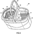
- Such bucket 100 has side walls 101 and a bottom 102 defining an interior space at least a lower portion defines a reservoir zone 110 adapted to receive a cleaning solution, for example a mixture of water and detergent.
- a cleaning solution for example a mixture of water and detergent.
- This reservoir comprises internal walls 111 substantially vertical at their bases and flaring at their vertices along an inclined plane 112 joining the side walls 101 of the bucket 100.
- These internal walls 111 are arranged face to face in the tank 110 and are separated at their base a distance slightly greater than the width of the base 50 of the blade 1.
- These walls further comprise horizontal ribs 113 for scraping the wipe 90 of the blade 1 when the cleaning head 50 is introduced into the tank 110 between the inner walls 111.
- the bucket 100 further comprises a wiper device 120 provided with a pierced basket 121 mounted within the bucket 100, above the reservoir zone 110, on a support 122: more specifically, the basket 121 is integral with a shaft 123 rotatably mounted on the support 122 via bearings 124. The basket 121 can thus rotate freely over the tank 110.
- This basket 121 has a truncated pyramid geometry substantially corresponding to the volume occupied by the head 50 of the blade 1 when it is in its folded position.
- the basket 121 comprises a substantially square bottom wall 122 and four side walls 123, pierced with orifices 124, inclined slightly towards the outside.
- These bottom walls 122 and lateral 123 further include ribs 125 for better cooperation with the head 50 of the blade 1.
- the bucket finally comprises a lid 130 provided with a first opening 131 located above the inner walls 111 of the tank 110, for plunging the blade 1 into the tank 110, and a second opening 132 located above the basket pierced 121, allowing the insertion of the brush head 50 into the basket 121.
- the lid further comprises a handle 133 for conveying the bucket 100.
- the base 60 is raised above the ground so that the immobilization mechanism is activated: as soon as the base 60 is brought into a position perpendicular to the handle 10, this position is locked by the rod 86 as described above.
- the inclined planes 112 of these walls 111 exert a force on the wings 70a, 70b which fold in their raised positions; once the latter are reached, the lugs 74a penetrate into the locking openings 62 and block the retracted position of the head 50.
- the wipe 90 which is fixed to the head tends to recall the external lateral portions 79a. wings to the inner side portions 79b.
- the cleats 76 do not completely press the immobilization tabs 64 against the bottom 101 of the bucket 100 so as not to completely disable the immobilization mechanism. Thanks to the latter, the involuntary inclination of the handle 10 around the inclination axis A is limited, which avoids unintentional release of the folded position of the head 50.
- the rotary drive device can be activated by sliding the sleeve 40 along the handle 10 several times: the head 50 and the basket 121 are thus rotatably driven together. around the longitudinal axis C of the handle 1, thus creating a centrifugal force for wringing the wipe 90, the expelled water being received in the reservoir 110 through the orifices 124.
- the head 50 is extracted from the pierced basket 121 and pressed against the ground S. This allows to partially press the immobilizing tabs 64 to the level of the cleats 76 and thus to slightly facilitate the inclination of the handle 10 around the axis of inclination A. Such inclination towards the front or back of the blade 1, exerted with sufficient force so that the foot 87 of the rod 86 mounts along the abutment surface 65, allows to unlock the wings 70a, 70b which are returned to their rest positions by the hinge springs 72.
- the cleaning head 50 is therefore in its working position and can be operated on the work surface S to clean the latter. When the user deems it necessary, a new cycle can begin.
Description
Le présent exposé concerne une tête de nettoyage et un balai pour nettoyage de surface faciles à utiliser et à essorer ainsi qu'un seau adapté pour son essorage.The present disclosure relates to a cleaning head and an easy-to-use, spin-drying surface cleaning brush and a bucket adapted for spinning.
Un tel balai, équipé par exemple d'une tête de lavage ou de dépoussiérage, permet de nettoyer les sols de manière commode tout en assurant un essorage facile et efficace de sa tête de nettoyage.Such a broom, equipped for example with a washing head or dedusting, makes it possible to clean the floors in a convenient manner while ensuring an easy and effective spinning of its cleaning head.
Afin de nettoyer plus commodément les sols, il est connu depuis quelques années des balais articulés équipés d'une tête de nettoyage comprenant par exemple une garniture en éponge ou en serpillière. De tels balais sont souvent plus efficaces et plus manoeuvrables que les balais à franges également connus. En particulier, la forme généralement rectangulaire de ces têtes de nettoyage assure un nettoyage facilité des coins de pièces tandis que leur articulation permet de nettoyer facilement sous les meubles. En outre, dans de tels balais, la garniture de nettoyage dispose d'un support rigide, ce qui permet d'exercer une force plus importante sur la surface de travail et donc d'enlever plus facilement les saletés.In order to more conveniently clean the floors, it has been known for some years articulated brushes equipped with a cleaning head comprising for example a sponge or mopping pad. Such brushes are often more efficient and more manoeuvrable than mops also known. In particular, the generally rectangular shape of these cleaning heads ensures easy cleaning of the corners of parts while their articulation makes it easy to clean under furniture. In addition, in such brushes, the cleaning pad has a rigid support, which allows to exert a greater force on the work surface and thus to remove more easily dirt.
Toutefois, ces balais doivent traditionnellement être plongés dans un seau contenant un liquide de nettoyage afin d'imbiber la garniture de nettoyage puis être essorés afin d'éliminer l'excès de liquide de nettoyage. Or, ces opérations sont traditionnellement rendues difficiles pour ce type de balai en raison de la taille et de la rigidité de leur tête de nettoyage : des seaux de grande taille et des dispositifs d'essorage complexes doivent ainsi être utilisés.However, these brushes must traditionally be immersed in a bucket containing a cleaning liquid to soak the cleaning pad and then be drained to remove excess cleaning fluid. However, these operations are traditionally made difficult for this type of broom because of the size and rigidity of their cleaning head: large buckets and complex wiping devices must be used.
En particulier, certains dispositifs d'essorage connus comprennent des racles ou des rouleaux disposés au sommet du seau ; toutefois, ces dispositifs sont difficiles d'utilisation en raison de l'instabilité du seau, ce dernier risquant en effet de se déplacer ou de se renverser lors de l'essorage.In particular, certain known wiper devices comprise squeegees or rollers arranged at the top of the bucket; however, these devices are difficult to use because of the instability of the bucket, the latter may indeed move or overturn during the spin.
D'autres dispositifs connus sont directement fixés et actionnables le long du manche du balai. Dans un tel cas, la tête de nettoyage doit généralement être redressée le long du manche pour permettre l'utilisation du dispositif d'essorage, ce qui nécessite une opération manuelle peu hygiénique. En outre, ces dispositifs sont souvent encombrants et peuvent réduire l'aptitude du balai à passer sous les meubles par exemple.Other known devices are directly fixed and operable along the handle of the brush. In such a case, the cleaning head must generally be straightened along the handle to allow the use of the spin device, which requires an operation unhygienic manual. In addition, these devices are often bulky and can reduce the ability of the broom to go under furniture for example.
On connaît également le document
Il existe donc un réel besoin pour une tête de nettoyage et un balai pour nettoyage de surface faciles à utiliser et à essorer ainsi qu'un seau adapté pour l'essorage de la tête de nettoyage, et qui soient dépourvus, au moins en partie, des inconvénients inhérents aux balais connus précités.There is therefore a real need for a cleaning head and an easy-to-use and wringing surface cleaning brush and a bucket adapted for the cleaning of the cleaning head, which are at least partially free of disadvantages inherent in known brushes above.
Le présent exposé concerne une tête de nettoyage pour balai, comprenant une portion de fixation adaptée pour fixer la tête de nettoyage sur un manche de balai, une base montée à l'extrémité inférieure de la portion de fixation par l'intermédiaire d'une articulation, et au moins deux ailes s'étendant depuis des bords latéraux opposés de la base, chaque aile étant apte à pivoter par rapport à la base entre une position de repos, dans laquelle elle s'étend sensiblement dans le prolongement de la base, et une position relevée, de manière à ce que la tête de nettoyage puisse être manoeuvrée entre une position de travail, sensiblement rectiligne, dans laquelle les ailes sont dans leurs positions de repos, et une position de repli, sensiblement en forme de U, dans laquelle les ailes sont dans leurs positions relevées.The present disclosure relates to a brush cleaning head, comprising a fastening portion adapted to attach the cleaning head to a brush handle, a base mounted at the lower end of the fastening portion via a hinge. , and at least two wings extending from opposite lateral edges of the base, each wing being pivotable relative to the base between a rest position, in which it extends substantially in the extension of the base, and a raised position, so that the cleaning head can be operated between a working position, substantially rectilinear, in which the wings are in their rest positions, and a folding position, substantially U-shaped, in which the wings are in their raised positions.
Grâce à cette tête de nettoyage articulée, un balai équipé de cette tête possède tous les avantages déjà évoqués de ce type de balai : il bénéficie en particulier d'une très bonne manoeuvrabilité, y compris dans les coins de pièces et sous les meubles, et d'une grande efficacité.Thanks to this articulated cleaning head, a broom equipped with this head has all the advantages already mentioned of this type of broom: it benefits in particular from a very good maneuverability, including in the corners of rooms and under furniture, and of great efficiency.
En outre, grâce à cette tête repliable en U, ce balai, une fois replié, bénéficie d'un encombrement réduit. Il est ainsi plus facile de le plonger dans un seau pour imprégner sa tête de nettoyage d'une solution de lavage ; la taille du seau peut en outre être réduite, ce qui est appréciable pour son rangement. D'ailleurs, grâce à ses ailes repliables, le balai est lui aussi plus facile à ranger. Il prend tout d'abord une place au sol réduite et bénéficie d'une station debout stable, ce qui n'est pas le cas des balais dont la tête se relève contre le manche.In addition, thanks to this collapsible U-shaped head, this broom, once folded, has a small footprint. It is thus easier to plunge it into a bucket to impregnate its cleaning head with a washing solution; the size of the bucket can also be reduced, which is significant for its storage. Moreover, thanks to its folding wings, the broom is also easier to store. It takes first place on the ground reduced and enjoys a stable standing, which is not the case for brooms whose head is up against the handle.
De plus, cette position repliée en U permet d'essorer facilement la tête de nettoyage dans un seau muni d'un panier d'essorage de la même manière qu'un balai à franges classique. Pour faciliter cette opération, un panier rectangulaire plutôt que circulaire peut être utilisé. Un tel essorage dans un panier d'essorage, permis par la géométrie en U de ce balai, est très facile et très efficace : il suffit d'exercer une pression verticale sur le manche pour comprimer la tête de nettoyage contre le panier. Dès lors, la position du seau est stable durant l'essorage, ce qui améliore son efficacité et réduit le risque de renversement du seau.In addition, this U-folded position makes it easy to wring the cleaning head into a bucket with a spin basket in the same manner as a conventional mop. To facilitate this operation, a rectangular rather than circular basket can be used. Such spin in a spin basket, enabled by the U-shape of this broom, is very easy and very effective: just exert a vertical pressure on the handle to compress the cleaning head against the basket. As a result, the bucket's position is stable during spinning, which improves its efficiency and reduces the risk of bucket spilling.
Dans certains modes de réalisation, la tête comprend au moins un dispositif de rappel configuré pour rappeler une aile vers sa position de repos. De cette manière, la tête de nettoyage est ramenée automatiquement vers la position de travail à l'issue de l'essorage sans que l'utilisateur n'ait à manipuler la tête, ce qui est hygiénique et plus confortable.In some embodiments, the head includes at least one biasing device configured to bias a wing toward its home position. In this way, the cleaning head is automatically returned to the working position after the spin without the user has to handle the head, which is hygienic and more comfortable.
Dans certains modes de réalisation, ce dispositif de rappel comprend un ressort de charnière.In some embodiments, this return device comprises a hinge spring.
Dans certains modes de réalisation, au moins l'un des éléments parmi l'une des ailes et la base comprend au moins deux parties aptes à se déplacer l'une par rapport à l'autre à l'encontre de moyens de rappel élastique pour réduire la longueur dudit élément, mesurée perpendiculairement aux axes de pivotement des ailes par rapport à la base. Par exemple, au moins l'une des ailes comprend une portion latérale interne par laquelle ladite aile est reliée à la base, et une portion latérale externe qui est apte à se déplacer vers la portion latérale interne à l'encontre de moyens de rappel élastique. Bien entendu, on peut prévoir que les deux ailes soient configurées de cette manière. Ainsi, lorsque les ailes passent de leur position de repos à leur position relevée, la longueur d'au moins l'un des tronçons de la tête (base ou aile) peut passagèrement diminuer pour éviter une augmentation globale de la longueur de la tête et permettre ainsi le passage de cette tête à sa position de repli en U sans étirement excessif de la garniture qui peut alors être fixée sur cette tête. Lorsque la tête est ensuite ramenée dans sa position de travail, les moyens de rappel élastique font revenir le tronçon concerné à sa longueur normale.In certain embodiments, at least one of one of the wings and the base comprises at least two parts able to move relative to each other against elastic return means for reduce the length of said element, measured perpendicularly to the pivot axes of the wings relative to the base. For example, at least one of the wings comprises an inner lateral portion through which said wing is connected to the base, and an outer lateral portion which is able to move towards the inner lateral portion against elastic return means . Of course, it is expected that the two wings are configured in this way. Thus, when the wings move from their rest position to their raised position, the length of at least one of the sections of the head (base or wing) can temporarily decrease to avoid an overall increase in the length of the head and thus allow the passage of this head to its U-fold position without excessive stretching of the seal which can then be fixed on this head. When the head is then returned to its working position, the elastic return means return the section concerned to its normal length.
Dans certains modes de réalisation, la tête comprend au moins un dispositif de blocage configuré pour maintenir une aile dans sa position relevée lorsqu'elle est amenée dans cette position. Ce dispositif de blocage permet de verrouiller la configuration en U de la tête au moment de l'essorage ou du rangement, ce qui augmente le confort d'utilisation. En particulier, ceci évite que la tête ne s'ouvre dans le seau, durant l'essorage, ou dans un placard, ce qui pourrait rendre difficile son extraction et sa manipulation.In some embodiments, the head includes at least one locking device configured to maintain a wing in its raised position when brought into that position. This blocking device locks the U-shaped configuration of the head at the time of spinning or storage, increasing user comfort. In particular, this prevents the head from opening in the bucket, during spinning, or in a closet, which could make it difficult to extract and handle.
Dans certains modes de réalisation, un des éléments parmi la base et ladite aile comprend au moins une ouverture de blocage, et l'autre desdits éléments parmi la base et ladite aile comprend un ergot sollicité vers l'extérieur à l'aide de moyens de rappel et configuré pour s'engager dans ladite ouverture de blocage lorsque l'aile est dans sa position relevée. De préférence ces moyens de rappel comprennent un ressort.In some embodiments, one of the base and said wing comprises at least one locking aperture, and the other of said elements among the base and said wing comprises a lug biased outwardly by means of reminder and configured to engage in said locking aperture when the wing is in its raised position. Preferably these return means comprise a spring.
Dans certains modes de réalisation, ladite ouverture de blocage est prévue sur la face dorsale de la base, et ladite aile comprend ledit ergot, ce dernier étant sollicité en direction de la base à l'aide desdits moyens de rappel. Cette configuration permet un déblocage facilité et centralisé au niveau de la base.In some embodiments, said locking aperture is provided on the dorsal face of the base, and said wing comprises said lug, the latter being biased toward the base by means of said biasing means. This configuration allows easy and centralized unlocking at the base.
Dans le présent exposé, les termes « ventral » et « dorsal » ainsi que leurs dérivés sont définis par rapport à la base de la tête de nettoyage, sa face ventrale étant destinée à être en contact avec la surface de travail.In this disclosure, the terms "ventral" and "dorsal" and their derivatives are defined relative to the base of the cleaning head, its ventral side being intended to be in contact with the work surface.
Dans certains modes de réalisation, les bords latéraux de la base possèdent une surface de guidage accompagnant ledit ergot jusqu'à l'ouverture de blocage lorsque l'aile est déplacée vers sa position relevée.In some embodiments, the side edges of the base have a guide surface accompanying said lug to the locking aperture when the wing is moved to its raised position.
Dans certains modes de réalisation, la tête comprend en outre au moins un dispositif de déblocage configuré, lorsqu'il est déclenché, pour désactiver ledit dispositif de blocage.In some embodiments, the head further comprises at least one unlocking device configured, when triggered, for disabling said blocking device.
Dans certains modes de réalisation, le dispositif de déblocage est configuré pour être déclenché en réponse à un mouvement prédéterminé de la portion de fixation par rapport à la base. Ainsi, l'utilisateur peut débloquer l'aile et ramener la tête de nettoyage vers sa position de travail en manoeuvrant uniquement le manche et non la tête de nettoyage elle-même, ce qui est hygiénique et plus confortable.In some embodiments, the unblocking device is configured to be triggered in response to a predetermined movement of the attachment portion relative to the base. Thus, the user can unlock the wing and return the cleaning head to its working position by manipulating only the handle and not the cleaning head itself, which is hygienic and more comfortable.
Dans certains modes de réalisation, le dispositif de déblocage est configuré pour être déclenché lorsque la portion de fixation est inclinée d'un angle prédéterminé par rapport à la base.In some embodiments, the unblocking device is configured to be triggered when the attachment portion is inclined at a predetermined angle to the base.
Dans d'autres modes de réalisation, le dispositif de déblocage est configuré pour être déclenché lorsque la portion de fixation est poussée d'une distance prédéterminée contre la base.In other embodiments, the unblocking device is configured to be triggered when the securing portion is pushed a predetermined distance from the base.
Dans certains modes de réalisation, la base comprend un levier de déblocage possédant une portion de repoussement configurée pour pénétrer dans ladite ouverture de blocage et repousser l'ergot afin de rompre sa coopération avec l'ouverture de blocageIn some embodiments, the base includes a release lever having a repetitive portion configured to penetrate into said locking aperture and urging the stub to break engagement with the locking aperture
Dans certains modes de réalisation, le levier de déblocage possède en outre une surface d'appui configurée pour coopérer avec un élément solidaire de la portion de fixation, la portion de repoussement du levier étant déplacée en direction de l'ouverture de blocage lorsque ledit élément solidaire de la portion de fixation déplace la surface d'appui en direction de la face ventrale de la tête de nettoyage.In some embodiments, the release lever further has a bearing surface configured to cooperate with an integral member of the attachment portion, the lever pushing portion being moved toward the locking aperture when said member secured to the attachment portion moves the bearing surface towards the ventral side of the cleaning head.
Dans certains modes de réalisation, ledit élément solidaire de la portion de fixation est une portion de came de l'articulation.In some embodiments, said integral member of the attachment portion is a cam portion of the hinge.
La tête comprend un dispositif d'immobilisation configuré pour bloquer au moins un degré de liberté de la base par rapport à la portion de fixation lorsque la base n'est pas en appui contre une surface de travail. Ceci est avantageux pour immobiliser la tête de nettoyage dans une position donnée par rapport au manche au cours de l'essorage par exemple. De cette manière, il est plus facile de manoeuvrer le balai dans un seau ou un dispositif d'essorage. En outre, le risque que le dispositif de déblocage ne se déclenche involontairement est réduit. Il faut préciser toutefois que si un tel dispositif d'immobilisation est particulièrement avantageux en combinaison avec le dispositif de blocage évoqué ci-dessus, il va de soi qu'il pourrait tout à fait équiper une tête de nettoyage dépourvue d'un tel dispositif de blocage voire même dépourvue d'ailes mobile : en effet, cette fonction d'immobilisation est intrinsèquement avantageuse quelle que soit le type de tête de nettoyage utilisée pour faciliter par exemple l'essorage comme cela est évoqué ci-dessus.The head includes an immobilizer configured to lock at least one degree of freedom of the base relative to the attachment portion when the base is not supported against a work surface. This is advantageous for immobilizing the cleaning head in a given position relative to the handle during the spinning for example. In this way, it is easier to maneuver the broom in a bucket or spin device. In addition, the risk that the unlocking device is triggered unintentionally is reduced. It should be pointed out, however, that if such an immobilizing device is particularly advantageous in combination with the blocking device mentioned above, it goes without saying that it could quite well equip a cleaning head devoid of such a device. blocking or even devoid of movable wings: indeed, this immobilization function is intrinsically advantageous regardless of the type of cleaning head used to facilitate for example the spin as mentioned above.
Dans certains modes de réalisation, l'articulation est configurée de manière à donner à la base deux degrés de liberté de rotation par rapport à la portion de fixation : un premier degré de liberté en rotation avant-arrière et un deuxième degré de liberté en rotation droite-gauche.In some embodiments, the hinge is configured to give the base two degrees of freedom of rotation relative to the attachment portion: a first degree of freedom in front-to-back rotation and a second degree of freedom in rotation right left.
Dans certains modes de réalisation, l'articulation comprend une première fourchette solidaire de la portion de fixation, une deuxième fourchette solidaire de la base et une pièce intermédiaire comprenant un premier axe d'articulation avec la première fourchette et un deuxième axe d'articulation avec la deuxième fourchette.In some embodiments, the hinge comprises a first fork secured to the fixing portion, a second fork secured to the base and an intermediate piece comprising a first hinge axis with the first fork and a second hinge pin with the second fork.
Dans certains modes de réalisation, le dispositif d'immobilisation est configuré pour immobiliser la base dans un plan sensiblement perpendiculaire à la portion de fixation.In some embodiments, the immobilizer is configured to immobilize the base in a plane substantially perpendicular to the attachment portion.
Dans certains modes de réalisation, la base comporte au moins une patte d'immobilisation, montée mobile dans un renfoncement de la face ventrale de la base entre une position saillante dans laquelle la patte fait saillie sous la face ventrale de la base et une position affleurante dans laquelle la patte affleure la face ventrale de la base, des moyens de rappel sollicitant la patte d'immobilisation en direction de sa position saillante. En outre, ladite patte coopère avec une première extrémité d'une tringle configurée pour coulisser au sein d'un passage de l'articulation, ladite tringle entravant au moins une partie de l'articulation lorsque la patte est dans sa position saillante. Ainsi, lorsque le balai est appuyé contre une surface de travail, la tringle n'entrave pas l'articulation et la tête de nettoyage peut être articulée librement pour assurer le nettoyage ; en revanche, lorsque la tête de nettoyage est levée du sol, par exemple au moment de son passage dans un seau ou de son essorage, au moins un degré de liberté de la tête de nettoyage est bloqué.In some embodiments, the base comprises at least one immobilization tab, mounted movably in a recess of the ventral face of the base between a projecting position in which the tab projects under the ventral face of the base and a flush position. wherein the tab is flush with the ventral face of the base, biasing means biasing the immobilizing tab towards its projecting position. In addition, said tab cooperates with a first end of a rod configured to slide within a passage of the hinge, said rod interfering with at least a portion of the hinge when the lug is in its projecting position. Thus, when the blade is pressed against a work surface, the rod does not interfere with the joint and the cleaning head can be articulated freely for cleaning; on the other hand, when the cleaning head is raised from the ground, for example at the time of its passage in a bucket or of its spinning, at least one degree of freedom of the cleaning head is blocked.
Dans certains modes de réalisation, une seconde extrémité de la tringle coopère avec une portion saillante d'une douille logée dans la portion de fixation, ladite portion saillante entravant au moins une partie de l'articulation lorsque la patte est dans sa position saillante. Ceci permet de bloquer un autre degré de liberté de la tête de nettoyage.In some embodiments, a second end of the rod cooperates with a protruding portion of a bushing housed in the attachment portion, said projecting portion impeding at least a portion of the hinge when the tab is in its projecting position. This makes it possible to block another degree of freedom of the cleaning head.
Dans certains modes de réalisation, un ressort est monté entre la douille et une portée de la portion de fixation.In some embodiments, a spring is mounted between the socket and a seat of the attachment portion.
Dans certains modes de réalisation, au moins une aile comprend au moins un taquet faisant sous la face ventrale de la base lorsque ladite aile est relevée. Ceci permet de maintenir actif, ou partiellement actif, le dispositif d'immobilisation même lorsque le balai est posé sur une surface, par exemple un panier d'essorage ou une surface de rangement, cette surface ne pouvant appuyer complètement sur la patte d'immobilisation en raison du taquet.In some embodiments, at least one wing comprises at least one cleat forming under the ventral face of the base when said wing is raised. This makes it possible to keep the immobilizer active, or partially active, even when the blade is placed on a surface, for example a drying basket or a storage surface. surface that can not fully press the locking tab due to the cleat.
Dans certains modes de réalisation, la tête comprend en outre une garniture imprégnable susceptible de retenir un liquide, cette garniture étant fixée de manière amovible sur la face ventrale de la tête de nettoyage.In some embodiments, the head further comprises an impregnable liner capable of retaining a liquid, which liner is removably attached to the ventral side of the cleaning head.
Dans d'autres modes de réalisation, il s'agit plutôt d'une garniture dépoussiérante. Une telle garniture peut notamment comporter des propriétés antistatiques et être imprégnée d'un additif de nettoyage telle une cire.In other embodiments, it is rather a dust pad. Such a liner may in particular comprise antistatic properties and be impregnated with a cleaning additive such as a wax.
Dans certains modes de réalisation, la garniture est fixée à l'aide d'au moins un bandeau élastique.In some embodiments, the liner is attached using at least one elastic band.
Dans certains modes de réalisation, la garniture est fixée à l'aide de bandes auto-agrippantes.In some embodiments, the liner is secured with Velcro strips.
Dans certains modes de réalisation, la base est de forme sensiblement rectangulaire, de préférence carrée. Ceci facilite la coopération du balai avec un panier d'essorage.In some embodiments, the base is of substantially rectangular shape, preferably square. This facilitates the cooperation of the broom with a spin basket.
Le présent exposé concerne en outre un balai pour nettoyage de surface comprenant un manche et une tête de nettoyage, selon l'un quelconque des modes de réalisation précédents, montée à l'extrémité inférieure du manche par l'intermédiaire de sa portion de fixation.The present disclosure further relates to a surface cleaning brush comprising a handle and a cleaning head, according to any one of the preceding embodiments, mounted at the lower end of the handle via its fixing portion.
Dans certains modes de réalisation, le balai comprend un dispositif d'entraînement en rotation longitudinale de la tête de nettoyage autour de l'axe longitudinal du manche. Ce dispositif permet d'essorer la tête de nettoyage par centrifugation, par exemple dans un seau muni d'un panier percé rotatif. Une telle méthode de centrifugation est plus efficace et nécessite moins d'effort que la méthode d'essorage par compression.In some embodiments, the wiper includes a longitudinal rotation drive device of the cleaning head about the longitudinal axis of the handle. This device makes it possible to spin the cleaning head by centrifugation, for example in a bucket provided with a rotary drilled basket. Such a centrifugation method is more efficient and requires less effort than the compression wringing method.
Dans certains modes de réalisation, le dispositif d'entraînement en rotation est un mécanisme du type toupie bourdonnante. Un tel mécanisme est particulièrement facile d'utilisation.In some embodiments, the rotational driving device is a buzzing router type mechanism. Such a mechanism is particularly easy to use.
Dans certains modes de réalisation, le dispositif d'entraînement en rotation est prévu dans le manche du balai.In some embodiments, the rotational drive is provided in the brush handle.
Dans certains modes de réalisation, le dispositif d'entraînement en rotation comprend une bague rotative configurée pour coopérer avec au moins une piste hélicoïdale d'un manchon coulissant autour du manche.In some embodiments, the rotational drive comprises a rotatable ring configured to cooperate with at least one helical track of a sleeve sliding around the handle.
Dans certains modes de réalisation, le dispositif d'entraînement en rotation comprend en outre un dispositif d'embrayage configuré pour solidariser la bague rotative avec une partie inférieure de manche lorsque le manchon est déplacé dans un premier sens le long du manche, et pour désolidariser la bague rotative de la partie inférieure de manche lorsque le manchon est déplacé dans le sens opposé. Ceci permet d'entraînement la tête de nettoyage toujours dans le même sens de rotation en effectuant des mouvements de va-et-vient avec le manchon.In some embodiments, the rotational drive further comprises a clutch device configured to secure the rotating ring to a lower handle portion when the sleeve is moved in a first direction along the handle, and to disengage. the rotating ring of the lower part of the handle when the sleeve is moved in the opposite direction. This allows driving the cleaning head always in the same direction of rotation by making movements back and forth with the sleeve.
Le présent exposé concerne également un seau, adapté pour coopérer avec un balai pour nettoyage de surface, comprenant un réservoir apte à contenir un liquide du type solution de nettoyage, et un dispositif d'essorage prévu au-dessus du réservoir et comprenant un panier percé apte à coopérer avec une tête de nettoyage d'un balai, le panier possédant une géométrie sensiblement de prisme ou de tronc de pyramide configurée pour recevoir une tête de nettoyage possédant une base sensiblement rectangulaire et des ailes s'étendant transversalement depuis des bords de la base. Un tel seau est donc particulièrement adapté pour une tête de nettoyage et un balai selon le présent exposé.The present disclosure also relates to a bucket, adapted to cooperate with a surface cleaning broom, comprising a reservoir capable of containing a liquid of the cleaning solution type, and a wiper device provided above the tank and comprising a pierced basket. adapted to cooperate with a cleaning head of a broom, the basket having a substantially prism or truncated pyramid geometry configured to receive a cleaning head having a substantially rectangular base and wings extending transversely from edges of the based. Such a bucket is therefore particularly suitable for a cleaning head and a broom according to the present disclosure.
Dans certains modes de réalisation, le dispositif d'essorage est monté en rotation afin de permettre un essorage d'une tête de nettoyage par centrifugation.In some embodiments, the wiper device is rotatably mounted to allow spinning of a cleaning head by centrifugation.
Dans certains modes de réalisation, le seau comprend au moins deux plans inclinés prévus en vis-à-vis au moins à l'entrée du réservoir, configurés pour coopérer avec des ailes d'une tête de nettoyage. Ces plans inclinés permettent de rabattre automatiquement les ailes de la tête de nettoyage dans leurs positions relevées lors de son insertion dans le seau.In some embodiments, the bucket comprises at least two inclined planes provided vis-à-vis at least at the inlet of the reservoir, configured to cooperate with the wings of a cleaning head. These inclined planes automatically fold the wings of the cleaning head in their raised positions when inserted into the bucket.
Dans certains modes de réalisation, au moins un desdits plans inclinés possède une surface rugueuse, munie par exemple de nervures. Cette dernière permet de retirer une partie des saletés présentes en surface de la tête de nettoyage.In some embodiments, at least one of said inclined planes has a rough surface, provided for example with ribs. The latter makes it possible to remove some of the dirt present on the surface of the cleaning head.
Dans certains modes de réalisation, le fond du panier comporte des nervures de support. Celles-ci permettent une meilleure coopération entre le panier et une tête de nettoyage.In some embodiments, the bottom of the basket has support ribs. These allow better cooperation between the basket and a cleaning head.
Dans certains modes de réalisation, ces nervures s'étendent depuis le centre du fond du panier et s'interrompent avant les parois latérales du panier.In some embodiments, these ribs extend from the center of the basket bottom and stop before the side walls of the basket.
Le présent exposé concerne enfin un ensemble comprenant un balai et un seau selon le présent exposé.The present disclosure finally relates to an assembly comprising a broom and a bucket according to the present disclosure.
Dans certains modes de réalisation, le panier percé est configuré de manière à coopérer avec la tête de nettoyage au niveau de la base et de l'extrémité des ailes uniquement.In some embodiments, the pierced basket is configured to cooperate with the cleaning head at the base and end of the wings only.
Dans certains modes de réalisation, les parois latérales du panier percé s'étendent plus haut que les ailes lorsque la tête de nettoyage est insérée dans le panier percé.In some embodiments, the side walls of the pierced basket extend higher than the wings when the cleaning head is inserted into the pierced basket.
Les caractéristiques et avantages précités, ainsi que d'autres, apparaîtront à la lecture de la description détaillée qui suit d'exemples de réalisation du balai et du seau proposés. Cette description détaillée fait référence aux dessins annexés.The above-mentioned features and advantages, as well as others, will become apparent on reading the following detailed description of embodiments of the proposed broom and bucket. This detailed description refers to the accompanying drawings.
Les dessins annexés sont schématiques et visent avant tout à illustrer les principes de l'invention.
- La
FIG 1 est une vue en perspective d'un exemple de réalisation d'un balai selon le présent exposé. - La
FIG 2 est une vue éclatée de la tête de ce balai. - La
FIG 3 est une vue en coupe de la tête de balai selon le plan III-III de laFIG 1 . - La
FIG 4A est en vue en coupe selon le même plan III-III lorsque la tête de balai est dans sa position de repli. - La
FIG 4B est une vue analogue à laFIG 4A lorsque le manche du balai est incliné. - La
FIG 4C est une vue en coupe selon le plan IV-IV de laFIG 4B . - La
FIG 5 est une vue en coupe de la tête de balai selon le plan V-V de laFIG 3 . - Le
FIG 6 est une vue analogue à laFIG 5 lorsque la tête de balai est levée au-dessus du sol. - La
FIG 7 est une vue éclatée de la partie supérieure du manche du balai. - La
FIG 8 est une vue en coupe de la partie supérieure du manche du balai. - La
FIG 9 est une vue en perspective d'un seau selon le présent exposé. - La
FIG 10 est une vue en coupe longitudinale de ce seau. - La
FIG 11 est une vue en coupe selon le plan XI-XI de laFIG 10 .
- The
FIG 1 is a perspective view of an embodiment of a broom according to the present disclosure. - The
FIG 2 is an exploded view of the head of this broom. - The
FIG 3 is a sectional view of the broom head according to the plane III-III of theFIG 1 . - The
FIG 4A is in sectional view on the same plane III-III when the mop head is in its folded position. - The
FIG 4B is a view similar to theFIG 4A when the broom handle is tilted. - The
FIG 4C is a sectional view along plane IV-IV of theFIG 4B . - The
FIG 5 is a sectional view of the mop head according to the VV plane of theFIG 3 . - The
FIG 6 is a view similar to theFIG 5 when the broom head is raised above the ground. - The
FIG 7 is an exploded view of the upper part of the broom handle. - The
FIG 8 is a sectional view of the upper part of the broom handle. - The
FIG 9 is a perspective view of a bucket according to the present disclosure. - The
FIG 10 is a longitudinal sectional view of this bucket. - The
FIG 11 is a sectional view according to plan XI-XI of theFIG 10 .
Afin de rendre plus concrète l'invention, des exemples de balai et de seau sont décrits en détail ci-après, en référence aux dessins annexés. Il est rappelé que l'invention ne se limite pas à ces exemples.In order to make the invention more concrete, examples of brush and bucket are described in detail hereinafter with reference to the accompanying drawings. It is recalled that the invention is not limited to these examples.
La
Les
La portion de fixation 51 comprend un taraudage 52 permettant le montage de l'extrémité inférieure filetée 11a du manche 10.The fixing
La base 60, de forme sensiblement carrée, est articulée avec la portion de fixation 51, et donc avec le manche 10, à l'aide de l'articulation 80. Cette articulation 80, prévue au niveau du centre géométrique de la base 60, c'est-à-dire à l'intersection des lignes médianes de sa surface dorsale 60a, comprend deux axes perpendiculaires de rotation A et B. Le premier axe de rotation A, dit axe d'inclinaison, est colinéaire à la direction de plus grande extension de la tête 50 : il est réalisé par des tourillons 81 de l'articulation 80 s'engageant dans les portées 61a d'une fourchette 61 de la base 60. Le deuxième axe de rotation B, perpendiculaire à l'axe A, est défini par des fusées 82 s'engageant dans des portées 83 de l'articulation 80 et 53a d'une fourchette 53 de la portion de fixation 51.The
Les deux ailes 70a, 70b sont aptes à pivoter par rapport à la base en étant articulées le long des extrémités latérales de la base 60 grâce à des axes de pivotement matérialisés par des arbres 71 : les ailes 70a, 70b peuvent ainsi s'étendre le long de la base 60 dans une position de repos, telle que représentée à la
Les ailes 70a, 70b comportent en outre chacune une cavité 73 s'ouvrant en bordure de l'aile 70a, 70b en vis-à-vis de la base 60. Dans cette cavité 73 est montée une douille 74 munie d'un ergot 74a. Un ressort 75 est monté entre cette douille et la paroi opposée de la cavité 73 de manière pousser l'ergot 74a hors de la cavité 73 en direction de la base 60.The
Par ailleurs, au moins l'une des ailes 70a, 70b (en l'espèce, il s'agit des deux ailes) comprend une portion latérale externe formant son extrémité 79a opposée à l'arbre de pivotement 71 et une portion latérale interne 79b, qui coopère avec l'arbre 71 pour relier l'aile à la base 60. Des ressorts 75' sont disposés entre les portions latérales externe et interne, ou entre la portion latérale externe et la base. Ainsi, la portion latérale externe 79a est normalement maintenue à légère distance de la portion latérale interne 79b mais elle peut s'en rapprocher lorsque la tête est repliée pour permettre ce repli sans risquer de déchirer la garniture qui est alors fixée à la tête. Du point de vue du maintien à distance des portions latérales externes par rapport aux portions latérales internes, les effets de rappel des ressorts 75 et 75' peuvent se conjuguer.Moreover, at least one of the
En l'espèce, le coulissement de la portion latérale externe 79a par rapport à la portion latérale interne 79b est guidé par un système de rail/coulisseau : la portion latérale externe 79a comprend des extensions 79'a qui viennent s'insérer dans des gorges de guidage 79'b que présente la portion latérale interne 79b. Les ressorts 75' sont maintenus dans des rainures 79"a que présentent les extensions 79'a. La structure pourrait être inverse, avec les gorges de guidage dans les portions latérales externes et les extensions sur les portions latérales internes.In this case, the sliding of the outer
La base 60 comprend quant-à-elle des ouvertures de blocage 62 traversant la paroi dorsale 60a de la base 60 dans une position telle que les ergots 74a des ailes 70a, 70b sont aptes à pénétrer dans ces ouvertures de blocage 62 lorsque les ailes 70a, 70b sont dans leurs positions relevées. Les bords latéraux de la base 60 sont arrondis afin que les ergots 74a puissent glisser facilement le long de ces bords jusqu'aux ouvertures de blocage 62.The
La base 60 comprend en outre des leviers de déblocage 63 ; chaque levier 63 est articulé autour d'un axe médian 63a et comprend à ses extrémités, de manière opposée, une portion de déblocage 63b et une surface d'appui 63c. La surface d'appui 63c s'étend au contact d'une portion de came 84 de l'articulation 80 comprenant un méplat 84a et des coins avant et arrières 84b. Grâce à cette portion de came 84, lorsque le manche 10 du balai 1 s'étend sensiblement perpendiculairement à la base 60 dans un plan avant-arrière, le méplat 84a est en contact avec la surface d'appui 63c, ce qui définit la position de repos du levier de déblocage 63 ; en revanche, lorsque le manche 10 est incliné en avant ou en arrière de la base 60, le coin avant ou arrière 84b de la portion de came 84 appuie sur la surface d'appui 63c du levier 63, ce qui déplace sa portion de repoussement 63b vers le haut. Cette dernière pénètre alors dans l'ouverture de blocage 62 et repousse l'ergot 74a de l'aile 70a ou 70b : dès lors, le ressort de charnière 72 rappelle l'aile 70a, 70b vers sa position de repos.The base 60 further comprises unlocking
La base 60 comprend en outre des pattes d'immobilisation 64. Chaque patte 64 est articulée au sein d'un renfoncement 65 de la base 60 autour d'un axe 64a entre une position affleurante, telle que représentée à la
La portion de fixation 51 comprend quant-à-elle une cavité 54 s'ouvrant en bordure inférieure de la portion de fixation 51 en vis-à-vis de l'articulation 80. Dans cette cavité 54 est montée une douille 55 munie d'un doigt 55a. Un ressort 56 est monté entre cette douille 55 et la paroi opposée de la cavité 54 de manière pousser le doigt 55a hors de la cavité 54 en direction de l'articulation 80.The fixing
L'articulation 80 comprend un passage longitudinal traversant 85 dans lequel coulisse une tringle 86. Cette tringle 86 possède un pied 87 dont la surface inférieure arrondie 87a coopère avec les portions d'appui 64b des pattes 64 ; elle possède à son extrémité supérieure un sommet 88 coopérant avec le doigt 55a de la douille 55 de la portion de fixation 51. La base 60 comprend en outre des surfaces du butée inclinées 66 s'étendant de part et d'autre du pied 87 de la tringle 86.The
Ainsi, lorsque le balai est appuyé contre une surface de travail S, comme cela est le cas sur la
Dans cette situation, l'interface entre le sommet 88 de la tringle 86 et le doigt 55a de la douille 55 se situe au sommet du passage 85 de l'articulation 80 : dès lors, la rotation du manche 10 autour de l'axe B de l'articulation 80 est libre (ceci est également visible sur la
En outre, dans cette situation, le manche 10 peut également être incliné autour de l'axe d'inclinaison A car, comme cela est mieux visible sur la loupe de la
En revanche, lorsque la tête 50 est levée au-dessus d'une surface de travail S, les pattes d'immobilisation 64 ne sont plus contraintes et peuvent rejoindre leurs positions saillantes : le ressort 56 repousse ainsi la douille 55, qui repousse la tringle 86, qui repousse les pattes 64.On the other hand, when the
Dans cette nouvelle situation, représentée notamment sur les
En outre, dans cette nouvelle situation, le pied 87 de la tringle 86 se situe plus bas et donc plus proche de la base 60 de telle sorte que ses surfaces de flanc 87b buttent contre les surfaces de butée 65 de la base 60 lorsque l'on tente de manoeuvrer le manche 10 du balai 1 autour de l'axe d'inclinaison A. Grâce à la pente des surfaces de butée 65, la rotation autour de l'axe d'inclinaison A n'est pas complètement empêchée : elle nécessite toutefois une force d'inclinaison plus importante pour vaincre les forces de friction au niveau des surfaces de butée 65 ainsi que la force de rappel du ressort 56. Toutefois, ceci est suffisant pour empêcher la tête 50 de s'incliner sous son propre poids lorsqu'elle est soulevée au-dessus du sol S.Moreover, in this new situation, the
Pour éviter également que ce mécanisme d'immobilisation ne soit désactivé de manière intempestive dans un seau ou au cours de l'essorage du balai 1 par exemple, les bordures intérieures des ailes 70a, 70b forment, lorsque ces dernières sont en position relevée, des taquets 76 faisant saillie sous la surface ventrale 60b de la base 60. Ainsi, lorsque la tête 50 est appuyée contre une surface, comme le fond d'un seau par exemple, les pattes d'immobilisation 64 ne sont que partiellement appuyées par ladite surface jusqu'au niveau des taquets 76. Dès lors, le pied 87 de la tringle 86 est légèrement remonté, ses surfaces de flanc 87b rencontrant les surfaces de butée 65 un peu plus haut, à proximité de leur extrémité supérieure : ceci facilite ainsi un peu l'inclinaison du manche 10 autour de l'axe d'inclinaison A sans toutefois l'autoriser complètement sans efforts.To also prevent this immobilization mechanism from being inadvertently deactivated in a bucket or during the wiping of the
Le manche 10 du balai 1 et son système d'entraînement en rotation longitudinale de la tête 50 vont maintenant être décrits plus en détail en référence aux
Le manche 10 comprend un tube inférieur 11 et un tube supérieur 12. Une pièce interface inférieure 21 est montée à l'extrémité supérieure du tube inférieur 11 : elle comprend une portion de fixation 21a, montée en force dans le tube inférieur 11, une portion dentée 21b et une portion tubulaire 21c ; un passage cylindrique longitudinal 21d la traverse presque jusqu'à son extrémité inférieure.The
Une pièce interface supérieure 22 est montée à l'extrémité inférieure du tube supérieur 12 : elle comprend une portion de fixation 22a, montée en force dans le tube supérieur 12, un renfoncement 22b et un passage cylindrique longitudinal 22c qui la traverse en totalité. La portion tubulaire 21c de la pièce interface inférieure 21 est en appui contre le fond du renfoncement 22b de la pièce interface supérieure 22. Deux rondelles 35 et 36, servant respectivement de rondelle de glissement (à faible coefficient de frottement) et de rondelle anti-bruit, peuvent être disposées autour de la portion tubulaire 21c, à l'intérieur du renfoncement 22b.An
Une tige 23 est introduite dans les passages 21d et 22c des pièces interfaces 21 et 22 et fixée à l'aide de goupilles 24 traversant les pièces interfaces 21, 22. Grâce à cette tige 23, les tubes inférieur 11 et supérieur 12 du manche 10 sont solidarisés.A
Une bague d'embrayage 30 est solidaire de la portion dentée 21b de la pièce interface inférieure 21 : elle comprend une pluralité de dents d'embrayages 21 présentant chacune un plan incliné d'un côté et une paroi abrupte de l'autre côté.A
Une bague rotative 32 est disposée autour de la portion tubulaire 21c entre la bague d'embrayage 30 et les rondelles 35 et 36 : elle peut ainsi coulisser le long et tourner autour de la portion tubulaire 21c. Elle comprend des dents d'entraînement 33 et des dents d'embrayage 34 présentant un profil complémentaire aux dents d'embrayage 31 de la bague d'embrayage 30. Un ressort 39, disposé entre un épaulement interne 37 de la bague rotative 32 et un épaulement 38 de la pièce interface inférieure 21, repousse la bague rotative 32 à distance de la bague d'embrayage 30.A
Un manchon 40 est disposé autour du manche 10 au niveau de la bague rotative 32. Ce manchon 40 est libre de coulisser le long du manche 10. Il est muni d'une pièce extrémité 41 montée à son extrémité inférieure. Une butée supérieure 42 est montée à l'extrémité supérieure du tube supérieur 12 et équipée d'un pommeau 49. La surface intérieure du manchon 40 présente des pistes hélicoïdales 43 coopérant avec les dents d'entraînement 33 de la bague rotative 32.A
Ainsi, lorsque le manchon est déplacé vers le bas depuis la butée supérieure 42, il entraîne la bague rotative 22 vers le bas jusqu'à ce que les dents d'embrayage 31, 34 de la bague d'embrayage 30 et de la bague rotative 32 se rencontrent, mettant en prise la bague rotative 32 avec la bague d'embraye 30. A partir de ce moment, lorsque le manchon continue de descendre, la bague rotative 32 ne pouvant coulisser plus bas, cette dernière est entraînée en rotation dans le sens horaire autour de l'axe longitudinal C du manche 10 par les pistes hélicoïdales 43 du manchon 40. Dès lors, grâce aux dents d'embrayages 31, 34 dont les parois abruptes se font face, la rotation horaire de la bague rotative 32 entraîne solidairement la rotation horaire de la bague d'embrayage 30 et donc de la pièce interface inférieure 21 et de tout le manche 10 ; la tête de nettoyage 50 étant solidaire du manche 10, elle est également entraînée en rotation longitudinale autour de l'axe C du manche 10.Thus, when the sleeve is moved downward from the
En revanche, lorsque le manchon 40 est déplacé vers le haut, le ressort 39 repousse la bague rotative 32 à distance de la bague d'embrayage 30, ce qui rompt leur coopération. Dès lors, lorsque la bague rotative 32 est en butée contre la rondelle 35, le mouvement vers le haut du manchon 40 entraîne la bague rotative 32 en rotation antihoraire. Toutefois, comme la bague rotative 32 et la bague d'embrayage 30 ne sont plus en prise, cette rotation antihoraire n'est pas communiquée au manche 10 ; ce dernier peut au contraire continuer de tourner en roue libre dans le sens horaire sous l'effet de son inertie.On the other hand, when the
Ainsi, des mouvements de va-et-vient du manchon 40 le long du manche 10 permettent d'entraîner continument ce dernier et la tête de nettoyage 50 en rotation horaire autour de l'axe longitudinal C du manche 10.Thus, reciprocating movements of the
Le manchon est en outre muni à son extrémité supérieure d'une nervure de blocage 44 susceptible d'être retenue dans une rainure de blocage 45 de la butée supérieure 42 : ce mécanisme permet de bloquer le manchon 40 lors du nettoyage du surface afin que la tête de nettoyage 50 ne puisse pas être entraînée en rotation longitudinale de manière intempestive.The sleeve is further provided at its upper end with a locking rib 44 which can be retained in a locking groove 45 of the upper stop 42: this mechanism makes it possible to block the
Un exemple de seau adapté pour être utilisé avec un balai selon la présente invention va maintenant être décrit en référence aux
Ce réservoir comprend des parois internes 111 sensiblement verticales à leurs bases et s'évasant à leurs sommets selon un plan incliné 112 rejoignant les parois latérales 101 du seau 100. Ces parois internes 111 sont disposées face à face dans le réservoir 110 et sont écartées à leur base d'une distance légèrement supérieure à la largeur de la base 50 du balai 1. Ces parois comportent en outre des nervures horizontales 113 permettant de racler la lingette 90 du balai 1 lorsque la tête de nettoyage 50 est introduite dans le réservoir 110 entre les parois internes 111.This reservoir comprises
Le seau 100 comprend en outre un dispositif d'essorage 120 muni d'un panier percé 121 monté au sein du seau 100, au-dessus de la zone de réservoir 110, sur un support 122 : plus précisément, le panier 121 est solidaire d'un arbre 123 monté en rotation sur le support 122 par l'intermédiaire de paliers 124. Le panier 121 peut ainsi tourner librement au-dessus du réservoir 110.The
Ce panier 121 possède une géométrie en tronc de pyramide correspondant sensiblement au volume occupé par la tête 50 du balai 1 lorsqu'elle est dans sa position de repli. Ainsi, le panier 121 comprend une paroi de fond 122 sensiblement carrée et quatre parois latérales 123, percées d'orifices 124, inclinées légèrement vers l'extérieur. Ces parois de fond 122 et latérales 123 comportent en outre des nervures 125 permettant une meilleure coopération avec la tête 50 du balai 1.This
Le seau comprend enfin un couvercle 130 muni d'une première ouverture 131 située au-dessus des parois interne 111 du réservoir 110, permettant de plonger le balai 1 dans le réservoir 110, et d'une deuxième ouverture 132 située au-dessus du panier percé 121, permettant l'insertion de la tête de balai 50 dans le panier 121. Le couvercle comprend en outre une poignée 133 de transport du seau 100.The bucket finally comprises a
Un exemple typique d'utilisation d'un tel balai 1 et d'un tel seau 100 va maintenant être décrit. Lors de son utilisation, la lingette 90 du balai 1 doit être imprégnée d'une solution de nettoyage : il faut pour cela plonger la tête 50 du balai 1 dans le seau 100.A typical example of using such a
Au début de cette opération, la base 60 est soulevée au-dessus du sol de telle sorte que le mécanisme d'immobilisation s'active : dès que la base 60 est amenée dans une position perpendiculaire au manche 10, cette position est verrouillée par la tringle 86 de la manière décrite plus haut.At the beginning of this operation, the
Puis, Lorsque la tête 50 est insérée entre les parois internes 111 du réservoir 110 du seau 100, les plans inclinés 112 de ces parois 111 exercent une force sur les ailes 70a, 70b qui se replient dans leurs positions relevées ; une fois ces dernières atteintes, les ergots 74a pénètrent dans les ouvertures de blocage 62 et bloquent la position de repli de la tête 50. Lors de ce repli, la lingette 90 qui est fixée à la tête, tend à rappeler les portions latérales externes 79a des ailes vers les portions latérales internes 79b. Les taquets 76 permettent de ne pas appuyer complètement les pattes d'immobilisation 64 contre le fond 101 du seau 100 afin de ne pas désactiver complètement le mécanisme d'immobilisation. Grâce à ce dernier, l'inclinaison involontaire du manche 10 autour de l'axe d'inclinaison A est limitée, ce qui évite un déblocage inopiné de la position de repli de la tête 50.Then, when the
Des mouvements de va-et-vient permettent alors de racler la lingette 90 à l'aide des nervures 113 des parois internes 111. Une fois la lingette 90 imprégnée de solution de nettoyage, la tête 50 est extraite du réservoir 110 et insérée dans le panier percé 121 du dispositif d'essorage 120. Si, par mégarde, la position de repli de la tête a été débloquée, les parois latérales inclinées 122 du panier 121 permettent également de replier facilement les ailes 70a, 70b lors de l'insertion de la tête 50 dans le panier 121.Reciprocating movements then make it possible to scrape the wipe 90 by means of the
Une fois la tête 50 insérée dans le panier percé 121, le dispositif d'entraînement en rotation peut-être activé en coulissant le manchon 40 le long du manche 10 à plusieurs reprises : la tête 50 et le panier 121 sont ainsi entraînés solidairement en rotation autour de l'axe longitudinal C du manche 1, créant ainsi une force centrifuge permettant d'essorer la lingette 90, l'eau expulsée étant reçue dans le réservoir 110 à travers les orifices 124.Once the
Une fois l'essorage terminé, la tête 50 est extraite du panier percé 121 et appuyée contre le sol S. Ceci permet d'appuyer partiellement sur les pattes d'immobilisation 64 jusqu'au niveau des taquets 76 et donc de faciliter légèrement l'inclinaison du manche 10 autour de l'axe d'inclinaison A. Une telle inclinaison vers l'avant ou l'arrière du balai 1, exercée avec une force suffisante pour que le pied 87 de la tringle 86 monte le long des surface de butée 65, permet de débloquer les ailes 70a, 70b qui sont rappelées vers leurs positions de repos par les ressorts de charnière 72.Once the spin is complete, the
La tête de nettoyage 50 se trouve dès lors dans sa position de travail et peut être manoeuvrée sur la surface de travail S pour nettoyer cette dernière. Lorsque l'utilisateur le juge nécessaire, un nouveau cycle peut débuter.The cleaning
Les modes ou exemples de réalisation décrits dans le présent exposé sont donnés à titre illustratif et non limitatif, une personne du métier pouvant facilement, au vu de cet exposé, modifier ces modes ou exemples de réalisation, ou en envisager d'autres, tout en restant dans la portée de l'invention.The modes or examples of embodiment described in the present description are given for illustrative and not limiting, a person skilled in the art can easily, in view of this presentation, modify these modes or embodiments, or to consider others, while remaining within the scope of the invention.
De plus, les différentes caractéristiques de ces modes ou exemples de réalisation peuvent être utilisées seules ou être combinées entre elles. Lorsqu'elles sont combinées, ces caractéristiques peuvent l'être comme décrit ci-dessus ou différemment, l'invention ne se limitant pas aux combinaisons spécifiques décrites dans le présent exposé. En particulier, sauf précision contraire, une caractéristique décrite en relation avec un mode ou exemple de réalisation peut être appliquée de manière analogue à un autre mode ou exemple de réalisation.In addition, the various features of these modes or embodiments can be used alone or be combined with each other. When combined, these features may be as described above or differently, the invention not being limited to the specific combinations described herein. In particular, unless otherwise specified, a characteristic described in connection with a mode or example of embodiment may be applied in a similar manner to another embodiment or embodiment.
Claims (12)
- A cleaning head for a mop comprising:a fixing portion (51) adapted to fix the cleaning head (50) on a mop (1) handle (10),a base (60) mounted at the lower end of the fixing portion (51) via a hinge (80),at least two wings (70a, 70b) extending from opposite side edges of the base (60), each wing (70a, 70b) being pivotable with respect to the base (60) between a rest position, in which it extends substantially in the extension of the base (60), and a raised position, so that the cleaning head (50) can to be maneuvered between- a substantially rectilinear working position in which the wings (70a, 70b) are in their rest positions, and- a substantially U-shaped folding position in which the wings (70a, 70b) are in their raised positions, characterized in that said cleaning head comprisesan immobilizer (86) configured to block at least a degree of freedom of the base (60) with respect to the fixing portion (51) when the base (60) is not bearing against a working surface (S).
- The head according to claim 1, wherein the base (60) includes at least one tab (64), movably mounted in a recess (65) of the ventral side (60b) of the base (60) between a protruding position in which the tab (64) protrudes on the ventral face (60b) of the base (60) and a flush position in which the tab (64) is flush with the ventral face (60b) of the base (60), return means (56) urging the tab (64) towards its protruding position, and
wherein said tab (64) cooperates with a first end (87) of a rod (86) configured to slide within a passage (85) of the hinge (80), said rod (86) interfering with at least part of the hinge (80) when the tab (64) is in its protruding position. - The head according to claim 2, wherein a second end (88) of the rod (86) cooperates with a protruding portion (55a) of a socket (55) housed in the fixing portion (51), said protruding portion (55a) interfering with at least part of the hinge (80) when the tab (64) is in its protruding position.
- The head according to any one of claims 1 to 3, comprising at least one return device (72) configured to return a wing (70a, 70b) towards its rest position.
- The head according to any one of claims 1 to 4, characterized in that at least one of the elements among one of the wings (70a, 70b) and the base (60) comprises at least two parts (79a, 79b) able to move relative to each other against elastic return means (75') in order to reduce the length of said element, measured perpendicular to the pivot axes of the wings with respect to the base.
- The head according to claim 5, characterized in that at least one of the wings (70a, 70b) comprises an inner side portion (79b) through which said wing is linked to the base (60), and an outer side portion (79a) able to move towards the inner side portion against elastic return means (75').
- The head according to any one of claims 1 to 6, comprising at least one blocking device (74a, 62) configured to maintain a wing (70a, 70b) in its raised position when it is brought into this position.
- The head according to claim 7, wherein one (60) of the elements among the base and said wing comprises at least one blocking aperture (62), and
wherein the other (70a, 70b) of said elements among the base and said wing comprises a lug (74a) urged outwardly by means of return means (75) and configured to engage said blocking aperture (62) when the wing (70a, 70b) is in its raised position. - The head according to claim 7 or 8, further comprising at least one unblocking device (63) configured, when it is triggered, to deactivate said blocking device (74a, 62), the unblocking device (63) being configured to be triggered in response to a predetermined movement of the fixing portion (51) with respect to the base (60).
- The head according to claim 8 or 9, wherein the base (60) comprises an unblocking lever (63) having a push-back portion (63b) configured to enter said blocking aperture (62) and push back the lug (74a) in order to break its cooperation with the blocking aperture (62), and
wherein the unblocking lever (63) further has a bearing surface (63c) configured to cooperate with a member (84) secured to the fixing portion (51), the push-back portion (63b) of the lever (63) being moved towards the blocking aperture (62) when said element (84) secured to the fixing portion (51) moves the bearing surface (63c) towards the ventral face (60b) of the cleaning head (50). - A mop for a surface cleaning, comprising a handle (10) and a cleaning head (50) according to any one of claims 1 to 10 mounted at the lower end of the handle (10) via its fixing portion (51).
- The mop according to claim 11, comprising a device for driving in longitudinal rotation (40, 32) the cleaning head (50) about the longitudinal axis (C) of the handle (10).
Applications Claiming Priority (1)
| Application Number | Priority Date | Filing Date | Title |
|---|---|---|---|
| FR1358866A FR3010622B1 (en) | 2013-09-13 | 2013-09-13 | AUTOMATIC TILTING HEAD BROOM FOR SURFACE CLEANING |
Publications (3)
| Publication Number | Publication Date |
|---|---|
| EP2848178A2 EP2848178A2 (en) | 2015-03-18 |
| EP2848178A3 EP2848178A3 (en) | 2015-06-03 |
| EP2848178B1 true EP2848178B1 (en) | 2019-02-13 |
Family
ID=49510395
Family Applications (1)
| Application Number | Title | Priority Date | Filing Date |
|---|---|---|---|
| EP14184688.1A Active EP2848178B1 (en) | 2013-09-13 | 2014-09-12 | Mop with an automatic tiltable head for surface cleaning |
Country Status (2)
| Country | Link |
|---|---|
| EP (1) | EP2848178B1 (en) |
| FR (1) | FR3010622B1 (en) |
Cited By (1)
| Publication number | Priority date | Publication date | Assignee | Title |
|---|---|---|---|---|
| KR20220164228A (en) * | 2021-06-04 | 2022-12-13 | 주식회사 케이엠 | Mop for cleaning |
Families Citing this family (12)
| Publication number | Priority date | Publication date | Assignee | Title |
|---|---|---|---|---|
| TWM528721U (en) * | 2015-04-30 | 2016-09-21 | Jiaxing Jackson Travel Prod Co | Hands free twist flat mop |
| GB201516618D0 (en) * | 2015-09-18 | 2015-11-04 | Numatic Int Ltd | Flat mop |
| CN105496325B (en) * | 2016-01-26 | 2019-04-19 | 骆庆林 | A kind of mop |
| CN105796026A (en) * | 2016-04-22 | 2016-07-27 | 孙振东 | Cleaning tool |
| DE102016121251B4 (en) * | 2016-11-07 | 2018-07-12 | Pfennig Reinigungstechnik Gmbh | Moppbezughalter |
| CN108606752B (en) * | 2018-05-08 | 2024-02-27 | 宁波德润堂智能科技有限公司 | Flat mop cleaning tool facilitating spin-drying operation |
| US11576550B2 (en) | 2018-05-29 | 2023-02-14 | Unger Marketing International, Llc | Flat headed mop |
| USD922712S1 (en) | 2019-01-28 | 2021-06-15 | Unger Marketing International, Llc | Flat headed mop |
| USD955075S1 (en) | 2019-01-28 | 2022-06-14 | Unger Marketing International, Llc | Bucket for floor cleaning |
| USD915703S1 (en) | 2019-05-28 | 2021-04-06 | Unger Marketng International, Llc | Flat headed mop |
| USD923896S1 (en) | 2019-05-28 | 2021-06-29 | Unger Marketing International, Llc | Floor cleaning system |
| TR202009542A2 (en) * | 2020-06-19 | 2020-07-21 | Sekeroglu Kimya Ve Plastik Sanayi Ve Ticaret Anonim Sirketi | Adjustable mop head for washing and mop positions |
Family Cites Families (4)
| Publication number | Priority date | Publication date | Assignee | Title |
|---|---|---|---|---|
| US6487746B1 (en) * | 2001-04-02 | 2002-12-03 | Kathyrn Cioci | Sponge mop with flexible ends |
| JP2004201716A (en) * | 2002-12-20 | 2004-07-22 | Fuji Enterp:Kk | Cleaning device |
| EP2175765A1 (en) * | 2007-07-09 | 2010-04-21 | Innocleaning Magma Holding B.V. | Mop head and method of mopping |
| US8640296B2 (en) * | 2010-01-11 | 2014-02-04 | Quickie Manufacturing Corporation | Adjustable cleaning head for a cleaning tool |
-
2013
- 2013-09-13 FR FR1358866A patent/FR3010622B1/en active Active
-
2014
- 2014-09-12 EP EP14184688.1A patent/EP2848178B1/en active Active
Non-Patent Citations (1)
| Title |
|---|
| None * |
Cited By (1)
| Publication number | Priority date | Publication date | Assignee | Title |
|---|---|---|---|---|
| KR20220164228A (en) * | 2021-06-04 | 2022-12-13 | 주식회사 케이엠 | Mop for cleaning |
Also Published As
| Publication number | Publication date |
|---|---|
| FR3010622A1 (en) | 2015-03-20 |
| EP2848178A3 (en) | 2015-06-03 |
| FR3010622B1 (en) | 2016-03-11 |
| EP2848178A2 (en) | 2015-03-18 |
Similar Documents
| Publication | Publication Date | Title |
|---|---|---|
| EP2848178B1 (en) | Mop with an automatic tiltable head for surface cleaning | |
| EP2769660B1 (en) | Broom with automatic tilting head for cleaning a surface | |
| EP0125994B1 (en) | Vacuum cleaning nozzle with a supporting wheel or with a sliding plate | |
| EP0494021B1 (en) | Hinged sponge mob | |
| EP2416692A1 (en) | Mop comprising a wringing module | |
| EP2362741B1 (en) | Telescopic vial for a liquid or pasty cosmetic product | |
| EP3496974A1 (en) | Sliding assembly for motor vehicle interior with improved comfort of use | |
| EP3624660B1 (en) | Autonomous vacuum cleaner with rotatable stem | |
| FR2927296A1 (en) | Funnel integrated stopper for e.g. water reservoir, of motor vehicle, has pins engaged in grooves to connect flaps such that rotation of flap rotates another flap, where flaps are separated across orifice by forming funnel between them | |
| FR2821540A1 (en) | Vacuum cleaner suction head has rollers and wiper mounted towards rear of head which is attached to hose by pivoted sleeve | |
| FR2642639A1 (en) | SHOVEL FOR THE PICKUP PICKUP IN PARTICULAR | |
| EP3923777B1 (en) | Wringing device for a mop | |
| EP4098170B1 (en) | Accessory for canister vacuum cleaner provided with a mobile joint cover | |
| EP3744222B1 (en) | Vacuum cleaner nozzle equipped with a locking device for locking at least one brush in a lowered position | |
| EP3922159A1 (en) | Cleaning head and rinsing device | |
| FR2952293A1 (en) | Apparatus for washing floor, has water vapor recovering tank placed in front of cleaning roller to recover condensated water vapor and detached stains from cleaning rag, and frame equipped with displacing unit to displace roller on floor | |
| EP3247247A1 (en) | Household electrical appliance comprising a work container and an engine housing pivotably mounted on a base | |
| EP4260783A1 (en) | Vacuum cleaner nozzle equipped with a wet cleaning device | |
| FR3040282A1 (en) | WASHING BROOM WITH FOLDABLE SOLE AND WASHING ASSEMBLY COMPRISING THE BROOM. | |
| EP4260779A1 (en) | Vacuum cleaner nozzle equipped with a wet cleaning device | |
| EP4260780A1 (en) | Vacuum cleaner nozzle equipped with a wet cleaning device | |
| EP4186401A2 (en) | Vacuum cleaner with secondary suction head | |
| WO2024023450A1 (en) | Cleaning unit for suction head | |
| EP4186402A2 (en) | Vacuum cleaner having a suction head movable between retracted and extended positions | |
| FR2930797A1 (en) | SWIMMING POOL CLEANING BRUSH |
Legal Events
| Date | Code | Title | Description |
|---|---|---|---|
| PUAI | Public reference made under article 153(3) epc to a published international application that has entered the european phase |
Free format text: ORIGINAL CODE: 0009012 |
|
| 17P | Request for examination filed |
Effective date: 20140912 |
|
| AK | Designated contracting states |
Kind code of ref document: A2 Designated state(s): AL AT BE BG CH CY CZ DE DK EE ES FI FR GB GR HR HU IE IS IT LI LT LU LV MC MK MT NL NO PL PT RO RS SE SI SK SM TR |
|
| AX | Request for extension of the european patent |
Extension state: BA ME |
|
| PUAL | Search report despatched |
Free format text: ORIGINAL CODE: 0009013 |
|
| AK | Designated contracting states |
Kind code of ref document: A3 Designated state(s): AL AT BE BG CH CY CZ DE DK EE ES FI FR GB GR HR HU IE IS IT LI LT LU LV MC MK MT NL NO PL PT RO RS SE SI SK SM TR |
|
| AX | Request for extension of the european patent |
Extension state: BA ME |
|
| RIC1 | Information provided on ipc code assigned before grant |
Ipc: A47L 13/58 20060101ALI20150424BHEP Ipc: A47L 13/256 20060101AFI20150424BHEP Ipc: A47L 13/258 20060101ALI20150424BHEP |
|
| R17P | Request for examination filed (corrected) |
Effective date: 20151202 |
|
| RBV | Designated contracting states (corrected) |
Designated state(s): AL AT BE BG CH CY CZ DE DK EE ES FI FR GB GR HR HU IE IS IT LI LT LU LV MC MK MT NL NO PL PT RO RS SE SI SK SM TR |
|
| 17Q | First examination report despatched |
Effective date: 20160701 |
|
| STAA | Information on the status of an ep patent application or granted ep patent |
Free format text: STATUS: EXAMINATION IS IN PROGRESS |
|
| GRAP | Despatch of communication of intention to grant a patent |
Free format text: ORIGINAL CODE: EPIDOSNIGR1 |
|
| STAA | Information on the status of an ep patent application or granted ep patent |
Free format text: STATUS: GRANT OF PATENT IS INTENDED |
|
| INTG | Intention to grant announced |
Effective date: 20180816 |
|
| GRAS | Grant fee paid |
Free format text: ORIGINAL CODE: EPIDOSNIGR3 |
|
| GRAA | (expected) grant |
Free format text: ORIGINAL CODE: 0009210 |
|
| STAA | Information on the status of an ep patent application or granted ep patent |
Free format text: STATUS: THE PATENT HAS BEEN GRANTED |
|
| AK | Designated contracting states |
Kind code of ref document: B1 Designated state(s): AL AT BE BG CH CY CZ DE DK EE ES FI FR GB GR HR HU IE IS IT LI LT LU LV MC MK MT NL NO PL PT RO RS SE SI SK SM TR |
|
| REG | Reference to a national code |
Ref country code: GB Ref legal event code: FG4D Free format text: NOT ENGLISH |
|
| REG | Reference to a national code |
Ref country code: CH Ref legal event code: EP Ref country code: AT Ref legal event code: REF Ref document number: 1095735 Country of ref document: AT Kind code of ref document: T Effective date: 20190215 |
|
| REG | Reference to a national code |
Ref country code: IE Ref legal event code: FG4D Free format text: LANGUAGE OF EP DOCUMENT: FRENCH |
|
| REG | Reference to a national code |
Ref country code: DE Ref legal event code: R096 Ref document number: 602014040940 Country of ref document: DE |
|
| REG | Reference to a national code |
Ref country code: LT Ref legal event code: MG4D |
|
| REG | Reference to a national code |
Ref country code: NL Ref legal event code: MP Effective date: 20190213 |
|
| PG25 | Lapsed in a contracting state [announced via postgrant information from national office to epo] |
Ref country code: FI Free format text: LAPSE BECAUSE OF FAILURE TO SUBMIT A TRANSLATION OF THE DESCRIPTION OR TO PAY THE FEE WITHIN THE PRESCRIBED TIME-LIMIT Effective date: 20190213 Ref country code: NO Free format text: LAPSE BECAUSE OF FAILURE TO SUBMIT A TRANSLATION OF THE DESCRIPTION OR TO PAY THE FEE WITHIN THE PRESCRIBED TIME-LIMIT Effective date: 20190513 Ref country code: NL Free format text: LAPSE BECAUSE OF FAILURE TO SUBMIT A TRANSLATION OF THE DESCRIPTION OR TO PAY THE FEE WITHIN THE PRESCRIBED TIME-LIMIT Effective date: 20190213 Ref country code: LT Free format text: LAPSE BECAUSE OF FAILURE TO SUBMIT A TRANSLATION OF THE DESCRIPTION OR TO PAY THE FEE WITHIN THE PRESCRIBED TIME-LIMIT Effective date: 20190213 Ref country code: PT Free format text: LAPSE BECAUSE OF FAILURE TO SUBMIT A TRANSLATION OF THE DESCRIPTION OR TO PAY THE FEE WITHIN THE PRESCRIBED TIME-LIMIT Effective date: 20190613 Ref country code: SE Free format text: LAPSE BECAUSE OF FAILURE TO SUBMIT A TRANSLATION OF THE DESCRIPTION OR TO PAY THE FEE WITHIN THE PRESCRIBED TIME-LIMIT Effective date: 20190213 |
|
| PG25 | Lapsed in a contracting state [announced via postgrant information from national office to epo] |
Ref country code: LV Free format text: LAPSE BECAUSE OF FAILURE TO SUBMIT A TRANSLATION OF THE DESCRIPTION OR TO PAY THE FEE WITHIN THE PRESCRIBED TIME-LIMIT Effective date: 20190213 Ref country code: RS Free format text: LAPSE BECAUSE OF FAILURE TO SUBMIT A TRANSLATION OF THE DESCRIPTION OR TO PAY THE FEE WITHIN THE PRESCRIBED TIME-LIMIT Effective date: 20190213 Ref country code: BG Free format text: LAPSE BECAUSE OF FAILURE TO SUBMIT A TRANSLATION OF THE DESCRIPTION OR TO PAY THE FEE WITHIN THE PRESCRIBED TIME-LIMIT Effective date: 20190513 Ref country code: GR Free format text: LAPSE BECAUSE OF FAILURE TO SUBMIT A TRANSLATION OF THE DESCRIPTION OR TO PAY THE FEE WITHIN THE PRESCRIBED TIME-LIMIT Effective date: 20190514 Ref country code: IS Free format text: LAPSE BECAUSE OF FAILURE TO SUBMIT A TRANSLATION OF THE DESCRIPTION OR TO PAY THE FEE WITHIN THE PRESCRIBED TIME-LIMIT Effective date: 20190613 Ref country code: HR Free format text: LAPSE BECAUSE OF FAILURE TO SUBMIT A TRANSLATION OF THE DESCRIPTION OR TO PAY THE FEE WITHIN THE PRESCRIBED TIME-LIMIT Effective date: 20190213 |
|
| REG | Reference to a national code |
Ref country code: AT Ref legal event code: MK05 Ref document number: 1095735 Country of ref document: AT Kind code of ref document: T Effective date: 20190213 |
|
| PG25 | Lapsed in a contracting state [announced via postgrant information from national office to epo] |
Ref country code: ES Free format text: LAPSE BECAUSE OF FAILURE TO SUBMIT A TRANSLATION OF THE DESCRIPTION OR TO PAY THE FEE WITHIN THE PRESCRIBED TIME-LIMIT Effective date: 20190213 Ref country code: DK Free format text: LAPSE BECAUSE OF FAILURE TO SUBMIT A TRANSLATION OF THE DESCRIPTION OR TO PAY THE FEE WITHIN THE PRESCRIBED TIME-LIMIT Effective date: 20190213 Ref country code: AL Free format text: LAPSE BECAUSE OF FAILURE TO SUBMIT A TRANSLATION OF THE DESCRIPTION OR TO PAY THE FEE WITHIN THE PRESCRIBED TIME-LIMIT Effective date: 20190213 Ref country code: SK Free format text: LAPSE BECAUSE OF FAILURE TO SUBMIT A TRANSLATION OF THE DESCRIPTION OR TO PAY THE FEE WITHIN THE PRESCRIBED TIME-LIMIT Effective date: 20190213 Ref country code: RO Free format text: LAPSE BECAUSE OF FAILURE TO SUBMIT A TRANSLATION OF THE DESCRIPTION OR TO PAY THE FEE WITHIN THE PRESCRIBED TIME-LIMIT Effective date: 20190213 Ref country code: EE Free format text: LAPSE BECAUSE OF FAILURE TO SUBMIT A TRANSLATION OF THE DESCRIPTION OR TO PAY THE FEE WITHIN THE PRESCRIBED TIME-LIMIT Effective date: 20190213 |
|
| REG | Reference to a national code |
Ref country code: DE Ref legal event code: R097 Ref document number: 602014040940 Country of ref document: DE |
|
| PG25 | Lapsed in a contracting state [announced via postgrant information from national office to epo] |
Ref country code: SM Free format text: LAPSE BECAUSE OF FAILURE TO SUBMIT A TRANSLATION OF THE DESCRIPTION OR TO PAY THE FEE WITHIN THE PRESCRIBED TIME-LIMIT Effective date: 20190213 Ref country code: PL Free format text: LAPSE BECAUSE OF FAILURE TO SUBMIT A TRANSLATION OF THE DESCRIPTION OR TO PAY THE FEE WITHIN THE PRESCRIBED TIME-LIMIT Effective date: 20190213 |
|
| PLBE | No opposition filed within time limit |
Free format text: ORIGINAL CODE: 0009261 |
|
| STAA | Information on the status of an ep patent application or granted ep patent |
Free format text: STATUS: NO OPPOSITION FILED WITHIN TIME LIMIT |
|
| PG25 | Lapsed in a contracting state [announced via postgrant information from national office to epo] |
Ref country code: AT Free format text: LAPSE BECAUSE OF FAILURE TO SUBMIT A TRANSLATION OF THE DESCRIPTION OR TO PAY THE FEE WITHIN THE PRESCRIBED TIME-LIMIT Effective date: 20190213 |
|
| 26N | No opposition filed |
Effective date: 20191114 |
|
| PG25 | Lapsed in a contracting state [announced via postgrant information from national office to epo] |
Ref country code: SI Free format text: LAPSE BECAUSE OF FAILURE TO SUBMIT A TRANSLATION OF THE DESCRIPTION OR TO PAY THE FEE WITHIN THE PRESCRIBED TIME-LIMIT Effective date: 20190213 |
|
| PG25 | Lapsed in a contracting state [announced via postgrant information from national office to epo] |
Ref country code: TR Free format text: LAPSE BECAUSE OF FAILURE TO SUBMIT A TRANSLATION OF THE DESCRIPTION OR TO PAY THE FEE WITHIN THE PRESCRIBED TIME-LIMIT Effective date: 20190213 |
|
| PG25 | Lapsed in a contracting state [announced via postgrant information from national office to epo] |
Ref country code: MC Free format text: LAPSE BECAUSE OF FAILURE TO SUBMIT A TRANSLATION OF THE DESCRIPTION OR TO PAY THE FEE WITHIN THE PRESCRIBED TIME-LIMIT Effective date: 20190213 |
|
| REG | Reference to a national code |
Ref country code: CH Ref legal event code: PL |
|
| PG25 | Lapsed in a contracting state [announced via postgrant information from national office to epo] |
Ref country code: LU Free format text: LAPSE BECAUSE OF NON-PAYMENT OF DUE FEES Effective date: 20190912 Ref country code: LI Free format text: LAPSE BECAUSE OF NON-PAYMENT OF DUE FEES Effective date: 20190930 Ref country code: CH Free format text: LAPSE BECAUSE OF NON-PAYMENT OF DUE FEES Effective date: 20190930 Ref country code: IE Free format text: LAPSE BECAUSE OF NON-PAYMENT OF DUE FEES Effective date: 20190912 |
|
| REG | Reference to a national code |
Ref country code: BE Ref legal event code: MM Effective date: 20190930 |
|
| PG25 | Lapsed in a contracting state [announced via postgrant information from national office to epo] |
Ref country code: BE Free format text: LAPSE BECAUSE OF NON-PAYMENT OF DUE FEES Effective date: 20190930 |
|
| GBPC | Gb: european patent ceased through non-payment of renewal fee |
Effective date: 20190912 |
|
| PG25 | Lapsed in a contracting state [announced via postgrant information from national office to epo] |
Ref country code: GB Free format text: LAPSE BECAUSE OF NON-PAYMENT OF DUE FEES Effective date: 20190912 |
|
| PG25 | Lapsed in a contracting state [announced via postgrant information from national office to epo] |
Ref country code: CY Free format text: LAPSE BECAUSE OF FAILURE TO SUBMIT A TRANSLATION OF THE DESCRIPTION OR TO PAY THE FEE WITHIN THE PRESCRIBED TIME-LIMIT Effective date: 20190213 |
|
| PG25 | Lapsed in a contracting state [announced via postgrant information from national office to epo] |
Ref country code: MT Free format text: LAPSE BECAUSE OF FAILURE TO SUBMIT A TRANSLATION OF THE DESCRIPTION OR TO PAY THE FEE WITHIN THE PRESCRIBED TIME-LIMIT Effective date: 20190213 Ref country code: HU Free format text: LAPSE BECAUSE OF FAILURE TO SUBMIT A TRANSLATION OF THE DESCRIPTION OR TO PAY THE FEE WITHIN THE PRESCRIBED TIME-LIMIT; INVALID AB INITIO Effective date: 20140912 |
|
| PG25 | Lapsed in a contracting state [announced via postgrant information from national office to epo] |
Ref country code: MK Free format text: LAPSE BECAUSE OF FAILURE TO SUBMIT A TRANSLATION OF THE DESCRIPTION OR TO PAY THE FEE WITHIN THE PRESCRIBED TIME-LIMIT Effective date: 20190213 |
|
| REG | Reference to a national code |
Ref country code: DE Ref legal event code: R082 Ref document number: 602014040940 Country of ref document: DE Representative=s name: CBDL PATENTANWAELTE GBR, DE |
|
| PGFP | Annual fee paid to national office [announced via postgrant information from national office to epo] |
Ref country code: IT Payment date: 20230921 Year of fee payment: 10 Ref country code: CZ Payment date: 20230823 Year of fee payment: 10 |
|
| PGFP | Annual fee paid to national office [announced via postgrant information from national office to epo] |
Ref country code: FR Payment date: 20230925 Year of fee payment: 10 Ref country code: DE Payment date: 20230927 Year of fee payment: 10 |