EP2847527B1 - Method for handling ice in connection with an ice dispenser - Google Patents
Method for handling ice in connection with an ice dispenser Download PDFInfo
- Publication number
- EP2847527B1 EP2847527B1 EP13787338.6A EP13787338A EP2847527B1 EP 2847527 B1 EP2847527 B1 EP 2847527B1 EP 13787338 A EP13787338 A EP 13787338A EP 2847527 B1 EP2847527 B1 EP 2847527B1
- Authority
- EP
- European Patent Office
- Prior art keywords
- ice
- auger
- agitator
- motor
- threshold value
- Prior art date
- Legal status (The legal status is an assumption and is not a legal conclusion. Google has not performed a legal analysis and makes no representation as to the accuracy of the status listed.)
- Not-in-force
Links
Images


Classifications
-
- F—MECHANICAL ENGINEERING; LIGHTING; HEATING; WEAPONS; BLASTING
- F25—REFRIGERATION OR COOLING; COMBINED HEATING AND REFRIGERATION SYSTEMS; HEAT PUMP SYSTEMS; MANUFACTURE OR STORAGE OF ICE; LIQUEFACTION SOLIDIFICATION OF GASES
- F25C—PRODUCING, WORKING OR HANDLING ICE
- F25C5/00—Working or handling ice
- F25C5/20—Distributing ice
- F25C5/24—Distributing ice for storing bins
-
- F—MECHANICAL ENGINEERING; LIGHTING; HEATING; WEAPONS; BLASTING
- F25—REFRIGERATION OR COOLING; COMBINED HEATING AND REFRIGERATION SYSTEMS; HEAT PUMP SYSTEMS; MANUFACTURE OR STORAGE OF ICE; LIQUEFACTION SOLIDIFICATION OF GASES
- F25C—PRODUCING, WORKING OR HANDLING ICE
- F25C2500/00—Problems to be solved
- F25C2500/08—Sticking or clogging of ice
-
- F—MECHANICAL ENGINEERING; LIGHTING; HEATING; WEAPONS; BLASTING
- F25—REFRIGERATION OR COOLING; COMBINED HEATING AND REFRIGERATION SYSTEMS; HEAT PUMP SYSTEMS; MANUFACTURE OR STORAGE OF ICE; LIQUEFACTION SOLIDIFICATION OF GASES
- F25C—PRODUCING, WORKING OR HANDLING ICE
- F25C2600/00—Control issues
- F25C2600/04—Control means
Definitions
- the present invention relates to food and beverage handling. More particularly, the invention relates to a novel, preferably integrated, ice and beverage dispenser wherein there is provided decoupled agitation and dispensing of ice.
- extruded ice also commonly known as pellet, nugget or chewable ice
- extruded ice forms ice blocks inside the storage bin and clumps easily resulting in clogged dispense mechanisms.
- US4846381 (A ) describes an ice dispenser comprising an ice storage chamber within which an agitator is rotatably mounted.
- a motor for driving the agitator is controlled in a predetermined timing sequence independent of a period during which ice pellets are dispensed from the ice storage chamber by means of an auger and a time interval intervening between the preceeding and succeeding ice dispensing operations.
- a first timer for driving first the agitator and a second timer for stopping the agitator for a predetermined period are provided in association with the agitator driving motor.
- US6093312 (A ) describes a combination water-purification and ice-dispensing system featuring an air cooler on the ice bin to prevent the congealing of ice.
- Four slanted agitator blades also break up chunks of ice back into ice cubes. Excess water from the ice maker is recycled into the ice maker. Double shutters prevent the dispensing of contaminated ice.
- An ice-bag dispenser and taper are included.
- a single kiosk can have both a purified water and an ice dispenser.
- the agitation is achieved with an agitator, preferably with the axis mounted horizontally.
- the ice is dispensed with an auger, also preferably installed horizontally.
- the present invention contemplates that the ice dispenser uses the force created by the auger to push the ice through an opening and out of the bin. This makes the dispensing more consistent and provides the ability to overcome any clumping. Also, by making the agitation action independent of the dispensing action, the incidence of clumping is reduced.
- the agitation is controlled by software or like control means, whereunder the agitator turns on based on the cumulative run time of the auger. Additionally, the auger run time and the agitation time (as well as other configurable parameters) preferably can be adjusted by DIP or like switches on or in communication with a control board or the like provided as part of the host dispenser.
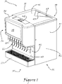
- an integrated ice and beverage dispenser 30 as particularly suitable and adapted for implementation of the methods and apparatus of the present invention is shown to generally comprise a conventional housing 36 disposed about an ice chute assembly 46 and an ice bin 69 and, most preferably, a plurality of beverage product nozzle assemblies 65, which are each conventionally provided with an activator 66 and like components.
- the various components of the integrated ice and beverage dispenser 30 are arranged on and about a conventional interior frame assembly, such as is well known to those of skill in the art, and which is typically supported atop a plurality of preferably self leveling feet 44, each of which feet 44 may additionally include such conventional features as nonskid bottoms 45 or the like.
- the housing 36 preferably comprises a wrapper 37 sized, shaped and otherwise adapted to extend about the sides 32 and back, or rear portion, of the dispenser 30 and which may, if desired in a particular implementation of the present invention, also be adapted to provide primary or supplemental thermal insulation for the ice bin 69 located within the interior 68 space of the dispenser 30.
- the housing 36 also preferably comprises a front cover 38 over and about the upper front 34 of the dispenser 30, which front cover 38 may be conventionally provided with a merchandizing panel 39.
- the front cover 38 as most preferably implemented in connection with the present invention is also sized, shaped and otherwise adapted to protectively enclose various components of the ice chute assembly 46 as well as all or various components of an agitator assembly 91, an auger assembly 123 and an ice dispensing circuit 133, each of which will be described in greater detail further herein.
- the housing 36 may also include a conventional splash plate 40 disposed about the front portion of the base 35 of the dispenser 30 as well as a conventional drip tray 67.
- the housing 36 also preferably comprises a lid 41 at the upper end 31 of the dispenser 31 for access to the ice bin 69, which lid 41 may be conventionally attached to the wrapper 37 of the housing 36 or other suitable portion of the dispenser 30 with hinges 43 or like attachments (or, alternatively, may simply rest atop the dispenser 30) and may conveniently be provided with one or more handles 42 for facilitating opening and/or removal.
- the ice chute assembly 46 as most preferably implemented for use in connection with the present invention, generally comprises a discharge chute 47 having dependently affixed thereto a cover 57.
- the discharge chute 47 dependently mounts to the front 34 of the dispenser 30 over and about an ice passage 71, which passage 71 extends from within the ice bin 69, through the front wall 70 of the ice bin 69 at the front 34 of the dispenser 30, to without the dispenser 30.
- the discharge chute 47 also itself comprises an ice passage 49, which passage 49 generally corresponds in size and shape to the ice passage 71 through the front wall 70 of the ice bin 69 at the front 34 of the dispenser 30.
- a gate 50 is provided and adapted to substantially close the ice passage 49 of the discharge chute 48 during periods between active dispensing of ice from the ice bin 69.
- a mounting pin 51 is utilized to hingedly affix the provided gate 50 to gate mounting arms 55 provided on the discharge chute 47 adjacent to and above the ice passage 49 thereof.
- a solenoid or like device may be coupled to the gate 50 for forcibly opening the gate 50 before activation of the auger assembly 123, as otherwise described herein with respect to the begin dispensing function 152 of Figure 14 , and/or forcibly closing the gate 50 following deactivation of the auger assembly 123, as otherwise described herein with respect to the end dispensing function 185 of Figure 19 .
- the exemplary begin dispensing function 152 of Figure 14 and/or the exemplary end dispensing function 185 of Figure 19 may readily be altered to include steps for sending appropriate control signals to such a solenoid or like device.
- the cover 57 over the discharge chute 47 is provided with a pair of cover mounting holes 59 which are sized, shaped and otherwise adapted to fit over and about a corresponding pair of cover mounting bosses 48 provided on the upper, outer sides of the discharge chute 47.
- the provided cover mounting holes 59 and corresponding cover mounting bosses 48 thus cooperate to hingedly attach the cover 57 to the discharge chute 47.
- an electric switch 53 which, as will be better understood further herein, is provided to signal to the ice dispensing circuit 133 that a user desires to obtain ice, is mounted to the discharge chute 47.
- a switch coupling 62 is provided mounted to the cover 57.
- a spring 61 formed in the cover 57 is positioned under and adjacent to a spring stop 54 provided on the discharge chute 47.
- the auger assembly 123 as most preferably implemented in accordance with the present invention is shown to generally comprise an auger, or screw, conveyor 124 and an electric motor 129.
- the auger conveyor 124 conventionally comprises a generally helical blade 125 coiled about an elongate drive shaft 126, the first, drive end 127 of which terminates in a drive bushing 131 of a gearbox 130 operably engaged with the electric motor 129.
- the second, distal end 128 of the drive shaft 126 is dependently rotationally supported by an auger bushing 75 (or journal bearing), which is preferably provided in the rear wall 73 of the ice bin 69.
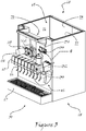
- the auger conveyor 124 as dependently supported between the drive bushing 131 and the auger bushing 75 is horizontally installed within the ice bin 69 of the integrated ice and beverage dispenser 30. Additionally, as particularly shown in Figure 7 , the horizontally installed auger conveyor 124 is also preferably installed along and adjacent to the second side wall 77 of the ice bin 69, as shown in the exemplary embodiment, or, in the alternative (not shown), along and adjacent to the first sidewall 76 of the ice bin 69. In any case, as clearly shown in Figures 7 and 8 , this orientation and location of the auger conveyor 124 enables the forced ejection of ice from any location adjacent to the chosen sidewall front to back within the ice bin 69.
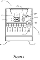
- the first, drive end 127 of the drive shaft 126 passes through the ice chute assembly 46 to the gearbox 130, which, along with the electric motor 129, is mounted to the outside of the ice chute assembly 47 through a provided auger motor mount 132, as most clearly depicted in Figure 4 .
- an elongate ovoid auger drive aperture 52, through which the first, drive end 127 of the drive shaft 126 passes, is provided through the gate 50 over the ice passage 49 of the discharge chute 47.
- the gate 50 may freely swing up and down, its operation being wholly unimpeded by the passage therethrough of the first, drive end 127 of the drive shaft 126.
- a slightly ovoid auger drive aperture 64 through which the first, drive end 127 of the drive shaft 126 also passes, is provided through the cover 57 over the discharge chute 47.
- the provision of the slightly ovoid auger drive aperture 64 through the cover 57 enables the cover 57 over the discharge chute 47 to rock freely within its previously described range of motion, its operation being wholly unimpeded by the passage therethrough of the first, drive end 127 of the drive shaft 126.
- the agitator assembly 91 as most preferably implemented in the accordance with the present invention is shown to generally comprise an agitator bar assembly 92 and an electric motor 118.
- the agitator assembly 91 may be operated separately and independently from the operation of the auger assembly 123 such that ice within the ice bin 69 may generally be agitated, jostled or the like at any desired time for agitation and regardless of whether at such a desired time for agitation ice is being dispensed from within the ice bin 69 and, likewise, ice may be dispensed from within the ice bin 69 at any desired time for dispensation and regardless of whether at such time for dispensation ice is being agitated within the ice bin 69.
- the term “decoupled” as applied to the agitation and dispensing operations under the present invention, or to the implementation under the present invention of the agitator assembly 91 and the auger assembly 123, shall be defined as referring to the described independence of operation.
- the term “decoupled” should not, however, imply that the two operations could not be simultaneously conducted, but rather that they may be independently conducted.
- the agitator bar assembly 92 as implemented in connection with the present invention preferably comprises a first, preferably canted paddle assembly 93 dependently radially supported from a drive shaft 115 and an adjacent second, preferably canted paddle assembly 104 also dependently radially supported from the drive shaft 115, the second paddle assembly 104 most preferably being provided generally opposite the first paddle assembly 93 with respect to the drive shaft 115, as most clearly depicted in Figure 7 .
- the paddle assemblies 93, 104 are during operation of the agitator assembly 91 rotated through the ice supply within the ice bin 69 by the drive shaft 115.
- a first, drive end 116 of the drive shaft 115 is operably interfaced with the provided electric motor 118 while a second, distal end 117 of the drive shaft is, on the other hand, dependently rotationally supported by an agitator bushing 74 (or journal bearing), which is preferably provided in the rear wall 73 of the ice bin 69, as particularly shown in Figures 7 and 9 .
- the electric motor 118 of the agitator assembly 91 is most preferably operably interfaced to the drive shaft 115 of the agitator bar assembly 92 through a gearbox 119 or, alternatively, a belt or chain drive, such that the electric motor 118 may operate at a conventional rotational speed while the drive shaft 115 and attached paddle assemblies 93, 104 are more moderately and gently, albeit forcefully, rotated through the ice contained within the ice bin 69.
- the drive shaft 115 of the agitator bar assembly 92 is also preferably connected through a provided drive coupling 121 to a separate drive shaft 120 extending from the gearbox 119.
- the electric motor 118 and gearbox 119 are dependently supported from the front 34 of the dispenser 30 by a provided agitator motor mount 122.
- the drive shaft 115 of the agitator bar assembly 92 as dependently supported between the drive coupling 121 (or other implemented interface to the electric motor 118) and the agitator bushing 74 is horizontally installed within the ice bin 69 of the ice and beverage dispenser 30.
- the horizontally installed drive shaft 115 of the agitator bar assembly 92 is also preferably installed at a generally central location within the ice bin 69 and in an orientation most preferably substantially parallel to the axis of rotation of the auger conveyor 124.
- first, preferably canted paddle assembly 93 and the second, preferably canted paddle assembly 104 are described in detail.
- the electric motor 118 and gearbox 119 are configured such that the agitator bar assembly will rotate in counterclockwise direction as viewed from the front 34 of the dispenser 30 to the back 33 of the dispenser 30.
- the first paddle assembly 93 comprises a first, "leading" radial arm 94 connected at a first end 95 thereof to the drive shaft 115 of the agitator bar assembly 93 and a second, “trailing" radial arm 97 connected at a first end 98 thereof to the drive shaft 115 of the agitator bar assembly 93.
- a paddle 100 which, in order to prevent excessive compaction of the extruded ice contained within the ice bin 69, preferably comprises a narrow blade-like structure 101, is connected at a first end 102 thereof to the second end 96 of the first, leading radial arm 94 of the first paddle assembly 93.
- the paddle 100 is connected at a second end 103 thereof to the second end 99 of the second, trailing radial arm 97 of the first paddle assembly 93.
- the first, leading radial arm 94 is most preferably positioned toward the "outside" of the first paddle assembly 93 adjacent to the front wall 70 of the ice bin 69 such that, as the agitator bar assembly 92 rotates through the ice, the ice encountered by the paddle 100 of the first paddle assembly 93 will tend to be jostled both toward the center of the ice bin 69 and toward the center of the auger conveyor 124.
- the second paddle assembly 104 comprises a first, "leading" radial arm 105 connected at a first end 106 thereof to the drive shaft 115 of the agitator bar assembly 93 and a second, “trailing" radial arm 108 connected at a first end 109 thereof to the drive shaft 115 of the agitator bar assembly 93.
- a paddle 111 which like the paddle 100 of the first paddle assembly 93 also preferably comprises a narrow blade-like structure 112, is connected at a first end 113 thereof to the second end 107 of the first, leading radial arm 105 of the second paddle assembly 104.
- the paddle 111 is connected at a second end 114 thereof to the second end 110 of the second, trailing radial arm 108 of the second paddle assembly 104.
- the first, leading radial arm 105 is most preferably positioned toward the "outside" of the second paddle assembly 104 adjacent to the rear wall 73 of the ice bin 69 such that, as the agitator bar assembly 92 rotates through the ice, the ice encountered by the paddle 111 of the second paddle assembly 104 will tend to be jostled both toward the center of the ice bin 69 and toward the center of the auger conveyor 124.
- the agitator bar assembly 92 preferably operates adjacent to and just above an agitator trough 82.
- the provided agitator trough 82 most preferably comprises a semicircular cross-section, the radius of which is only slightly greater than the radius of the circular path traversed by the outermost portions of the paddles 100, 111 of the agitator bar assembly 92.
- the auger, or screw, conveyor 124 preferably operates adjacent to and just above a separate auger trough 84, which preferably is located a distance above and laterally offset from the lowermost portion of the agitator trough 82.
- the provided auger trough 84 most preferably comprises a semicircular cross-section, the radius of which is only slightly greater than the radius of the circular path traversed by the outermost portions of the blade 125 of the auger conveyor 124.
- the bulk of the ice within the ice bin 69 may periodically be gently jostled separate and apart from the relatively small portion of ice that has found its way into contact with the helical blade 125 of the auger conveyor 123 and which, as a consequence, may have suffered some degree of compaction.
- the described troughs 82, 84 could readily be formed as the floor of the ice bin 69, the most preferred implementation of the present invention contemplates that the troughs 82, 84 will be provided in connection with an ice bin insert 81 adapted to rest upon the floor 79 of the ice bin 69, thereby serving to separate the ice bin 69 into an upper compartment 79 and a lower compartment 80.
- the present invention additionally provides means for servicing of a cold plate 89, which, as is well known to those of ordinary skill in the art, comprises a block structure of thermally conductive material through which is provided one or more internal beverage product passages 90 in fluid communication with one or more beverage product nozzle assemblies 65.
- the ice bin insert 81 is provided with a plurality of apertures 83 through which small quantities of extruded ice may fall from the upper compartment 79 to the lower compartment 80 as ice in the lower compartment 80 melts.
- the methods of the present invention specifically support this arrangement inasmuch as the agitator assembly 91 may be operated independently of whether ice is dispensed by the auger assembly 123 in order to periodically jostle the ice over and above the apertures 83, thereby ensuring that ice bridges do not form over the apertures 83 and, consequently, that there is always a ready supply of ice in the lower compartment 80.
- the floor 78 of the of the ice bin 69 is preferably sloping (as depicted, forward sloping) such that as ice in the lower compartment 80 melts the resulting water may drain through a provided drain connection 135.
- the front face 85 and the rear face 87 of the ice bin insert 81 are adapted to accommodate the sloping floor 78 such that as the bottom edges 85, 88, respectively, of the faces 85, 87 rest upon the floor 78 the agitator trough 82 and the auger trough 84 remain substantially level and in close conformance about the agitator assembly 92 and the auger conveyor 124, respectively.
- a needsAgitate variable is set (step 138) to FALSE to indicate that the agitator assembly 91 need not at the present time be activated solely as a matter of the passage of time.
- an augerRunTime variable which tracks the cumulative time that the auger assembly 123 has operated since the beginning of the most previous activation of the agitator assembly 91 and, consequently, serves as a measure of the depletion of ice in and about the auger trough 82 and auger conveyor 124 due to the dispensing of ice, is initialized (step 139) to ZERO.
- a timeLastAgitate variable which tracks the time at which the most previous activation of the agitator assembly 91 began, is initialized (step 140) to the then present time timeNow.
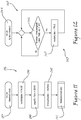
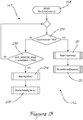
- the main ice control program calls (step 141) the monitor ice controls routine 142, as shown in Figure 13 , under which the routine 142 cycles through a repeat loop 149 to determine (1) whether the lever arm 60 of the integral activator 58 has been deflected by a user, indicating that the user desires that ice be dispensed, or (2) whether agitation of the ice within the ice bin 69 is required as a matter of the passage of time as determined by the agitation monitor routine 143 of Figure 12 .
- the agitation monitor routine 143 of Figure 12 is a routine that allows for activation and operation of the agitator assembly 91 solely as a matter of the passage of time. While the agitation monitor routine 143 need not be implemented in order to realize at least some aspects of the present invention, it is noted that the routine 143 is particularly useful and desired for ensuring that ice within the ice bin 69 does not freeze into clumps between agitation cycles triggered in response to dispensing operations and/or that ice in the lower compartment 80 of the ice bin 69 is replenished upon melting. In any case, utilization of an implemented agitation monitor routine 143 may be controlled by selecting the utilization of the feature with DIP switches 134 or the like provided on the ice dispensing circuit 133.
- the agitation monitor routine 143 will generally start (step 144) concurrently with the main ice control program 136. Under the agitation monitor routine 143, a repeat loop 145 operates to continuously determine whether the elapsed time since the time at which the most previous activation of the agitator assembly 91 began, i.e. timeNow - timeLastAgitate, has exceeded a preferably user configurable constant MAX_TIME_AGIT_OFF indicating the maximum length of time that should ever pass without activation of the agitator assembly (step 146).
- variable needsAgitate is set (step 147) to TRUE and the condition is handled by the monitor ice controls routine 142 of Figure 13 as described further herein.
- a repeat loop 149 operates to determine (1) whether the lever arm 60 of the integral activator 58 has been deflected (step 150), indicating that a user desires that ice be dispensed, or (2) whether agitation of the ice within the ice bin 69 is required (a) as a matter of the passage of time as determined by the agitation monitor routine 143 of Figure 12 (step 203) and (b), as indicated by a TRUE value of a flag AGIT_MONITOR_ENAB, the optional monitoring implemented by the agitation monitor routine 143 is active.
- the repeat loop 149 continues to cycle. If, on the other hand, either condition checks TRUE, the first in condition sequence to so check will trigger additional action. In particular, if it is first determined that the lever arm 60 of the integral activator 58 has been deflected (step 150), the monitor ice controls routine will operate to first call (step 151) the begin dispensing function 152 of Figure 14 , thereby causing, as described further herein, activation of the auger assembly 123.
- the monitor ice controls routine 142 Upon return from the begin dispensing function 152, the monitor ice controls routine 142 will then operate to call (step 156) the monitor normal dispense routine 157 of Figure 15 , under which, as will be better understood further herein, the depletion of ice in and about the auger trough 82 and auger conveyor 124 due to the dispensing of ice is monitored as ice is dispensed from the ice bin 69, thereby ensuring that sufficient ice supply remains available throughout the dispensing operation.
- the monitor ice controls routine 142 will operate to first call (step 204) the begin agitation function 165 of Figure 16 , thereby causing, as described further herein, activation of the agitator assembly 91.
- the monitor ice controls routine 142 Upon return from the begin agitation function 165, the monitor ice controls routine 142 will then operate to call (step 205) the monitor timed agitation routine 206 of Figure 21 , under which, as will be better understood further herein, the routine 206 operates to monitor whether, during passage of the established time for agitation, the lever arm 60 of the integral activator 58 has been deflected (step 209), indicating that a user desires that ice be dispensed and, if so, ensures that the user's desire is immediately acted upon.
- the monitor ice controls routine 142 will operate to first call (step 151) the begin dispensing function 152 of Figure 14 .
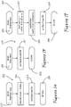
- the timeLastDispense variable is set (step 154) to the then present time timeNow and a control signal is sent (step 224) to activate the electric motor 129 of the auger assembly 123, the details of implementation of such control signal being well within the ordinary skill in the art.
- the auger assembly 123 will then begin operating to dispense ice from the ice bin 69 through the ice chute assembly 46.
- the begin dispensing function 152 upon sending (step 224) of the control signal to activate the auger assembly, the begin dispensing function 152 will then return (step 155) to the program flow location immediately following that from which the function 152 was called, which in the present case is back to the monitor ice controls routine 142 of Figure 13 to then call (step 156) the monitor normal dispense routine 157 of Figure 15 .
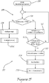
- a repeat loop 159 is initiated under which (1) the continued deflection or release of the lever arm 60 of the integral activator 58 is monitored and determined and (2) the total time that the auger assembly 123 has operated since the beginning of the most previous activation of the agitator assembly 91 is monitored to ensure that ice in and about the auger trough 82 and auger conveyor 124 remains sufficient to continue the dispensing operation without need for replenishment through activation of the agitator assembly 91.
- the monitor normal dispense routine 157 escapes the repeat loop 159 and immediately calls (step 201) the end dispensing function 185 of Figure 19 .
- a timeDispensing variable is calculated (step 187) as the length of time elapsed under the present dispensing operation; the calculated dispensing time is added (step 188) to the cumulative augerRunTime variable, which, as previously discussed, tracks the cumulative time that the auger assembly 123 has operated since the beginning of the most previous activation of the agitator assembly 91; and a control signal (the details of implementation of such control signal being well within the ordinary skill in the art) is sent (step 189) to deactivate the electric motor 129 of the auger assembly 123, after which the end dispensing function 185 will then return (step 190) to the program flow location immediately following that from which the function 185 was called, which in the present case is back the monitor normal dispense routine 157 of Figure 15 to then call (step 202) the monitor ice controls routine 142 of Figure 13 , which routine 142, it is noted, will start anew at its beginning step (step148).
- step 160 the repeat loop 159 continues to determine whether the quantity of ice in and about the auger trough 82 and auger conveyor 124 due to the dispensing of ice has likely been depleted to a level where there is imminent risk that the ice supply will be insufficient to continue the dispensing operation.
- the timeDispensing variable is calculated (step 161) as the length of time elapsed under the present dispensing operation and the sum of the calculated dispensing time and the cumulative augerRunTime variable is compared (step 162) to a REFILL_DELAY constant, which is a configured estimated or otherwise predetermined time over which dispensing may safely take place before it may be expected that ice in and about the auger trough 82 and auger conveyor 124 will likely be imminently depleted due to the ongoing dispensing of ice. If the calculated sum does not exceed the REFILL_DELAY constant, the repeat loop 159 continues.
- the monitor normal dispense routine 157 escapes the repeat loop 159 and sets (step 163) the timeLastDispense variable to the then present time timeNow and immediately calls (step 164) the begin agitation function 165 of Figure 16 to activate the agitator assembly 91.
- the begin agitation function 165 reinitializes (step 167) the needsAgitate variable to FALSE; reinitializes (step 168) the augerRunTime variable to ZERO; sets (step 169) the timeLastAgitate variable to the then present time; and then sends (step 170) a control signal to activate the electric motor 118 of the agitator assembly 91, the details of implementation of such control signal being well within the ordinary skill in the art.
- the agitator assembly 91 will then begin operating, as previously discussed, to jostle the ice within the ice bin 69 and, in the course thereof, will replenish the ice in and about the auger trough 82 and auger conveyor 124.
- the begin agitation function 165 upon sending (step 170) of the control signal to activate the agitator assembly 91, the begin agitation function 165 will then return (step 171) to the program flow location immediately following that from which the function 165 was called, which in the present case is back the monitor normal dispense routine 157 of Figure 15 to then call (step 172) the monitor replenishment routine 173 of Figure 17 , which serves to ensure that once agitation begins during a normal dispensing operation, ample time elapses to ensure that replenishment of the ice in and about the auger trough 82 and auger conveyor 124 is sufficient to either return to the monitor normal dispense routine 157 of Figure 15 or (as will be better understood further herein) to the monitor ice controls routine 142 of Figure 13
- a repeat loop 175 is initiated under which it is determined (1) whether the lever arm 60 of the integral activator 58 continues to be deflected and, if so, (2) whether sufficient replenishment time has elapsed to return to the monitor normal dispense routine 157 of Figure 15 .
- the monitor replenishment routine 173 determines that the lever arm 60 of the integral activator 58 remains deflected (step 176)
- the monitor replenishment routine 173 determines (step 177) whether the elapsed time since the time at which the most previous activation of the agitator assembly 91 began, i.e.
- the REFILL TIME constant is a configured expected "worst case" minimum agitation time required to replenish ice in and about the auger trough 82 and auger conveyor 124 to a "filled" level such that it may safely be expected that dispensing of ice may continue for a time period of at least the REFILL_DELAY time before it may again be expected that ice in and about the auger trough 82 and auger conveyor 124 will again likely be imminently depleted due to the ongoing dispensing of ice. If the elapsed time since the time at which the most previous activation of the agitator assembly 91 began has not exceeded the REFILL_TIME constant, the repeat loop 175 continues.
- the repeat loop 175 escapes and the monitor replenishment routine 173 immediately calls (step 178) the end agitation function 179 of Figure 18 .
- the end agitation function 179 upon starting (step 180) of the end agitation function 179, the end agitation function 179 simply sends (step 181) a control signal to deactivate the electric motor 118 of the agitator assembly 91, the details of implementation of such control signal being well within the ordinary skill in the art.
- step 181 Upon sending (step 181) the control signal, the end agitation function 179 will then return (step 182) to the program flow location immediately following that from which the function 179 was called, which in the present case is back the monitor replenishment routine 173 of Figure 17 to then call (step 183) the monitor normal dispense routine 157 of Figure 15 , which routine 157, it is noted, will start anew at its beginning step (step 158).
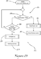
- the monitor replenishment routine 173 of Figure 17 determines that the lever arm 60 of the integral activator 58 no longer remains deflected, the repeat loop 175 escapes and the monitor replenishment routine 173 immediately calls (step 184) the end dispensing function 185 of Figure 19 , as has been previously described. Upon return from execution of the end dispensing function 185, the monitor replenishment routine 173 then calls (step 191) the monitor complete replenishment routine 192 of Figure 20 .
- the agitator assembly 91 is allowed to continue to operate until sufficient time has elapsed since the time at which the most previous activation of the agitator assembly 91 began to ensure that the area in and about the auger trough 82 and auger conveyor 124 has been replenished with ice. Additionally, during completion of the replenishment operation, the monitor complete replenishment routine 173 monitors the status of the lever arm 60 of the integral activator 58 in order to respond to any additional user request for dispensing of ice.
- a repeat loop 194 is initiated to determine (1) whether the lever arm 60 of the integral activator 58 has been deflected (step 195), indicating that a user again desires that ice be dispensed, or, if not, (2) whether sufficient replenishment time has elapsed to return to the monitor ice controls routine 142 of Figure 13 (step 198).
- the monitor complete replenishment routine 192 first determines that the lever arm 60 of the integral activator 58 has been deflected (step 195), the repeat loop 194 escapes and the monitor complete replenishment routine 192 immediately calls (step 196) the begin dispensing function 152 of Figure 14 , as has been previously described in detail, and, upon return from the begin dispensing function 152, the monitor complete replenishment routine 192 then calls (step 197) the monitor replenishment routine 173 of Figure 17 , as has also been previously described in detail and which routine 173, it is noted, will start anew at its beginning step (step174).
- the monitor complete replenishment routine 192 of Figure 20 first determines that the elapsed time since the time at which the most previous activation of the agitator assembly 91 began, i.e. timeNow - timeLastAgitate, has exceeded the REFILL_TIME constant (step 198), indicating that the area in and about the auger trough 82 and auger conveyor 124 has been sufficiently replenished with ice, the repeat loop 194 escapes and the monitor complete replenishment routine 192 immediately calls (step 199) the end agitation function 179 of Figure 18 , as has been previously described in detail, and, upon return from the end agitation function 179, the monitor complete replenishment routine 192 then calls (step 200) the monitor ice controls routine 142 of Figure 13 , as has also been previously described in detail and which routine 142, it is noted, will start anew at its beginning step (step148).
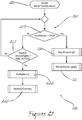
- the monitor ice controls routine 142 will escape its repeat loop 149 and operate to first call (step 204) the begin agitation function 165 of Figure 16 , thereby causing, as has previously been described in detail, activation of the agitator assembly 91, and, upon return from the begin agitation function 165, the monitor ice controls routine 142 will then operate to call (step 205) the monitor timed agitation routine 206 of Figure 21 , under which, the routine 206 will operate to monitor whether, during passage of the established time for agitation, the lever arm 60 of the integral activator 58 has been deflected (step 209), indicating that a user desires that ice be dispensed and, if so, ensures that the user's desire is immediately acted upon.
- a repeat loop 208 is initiated to determine (1) whether the lever arm 60 of the integral activator 58 has been deflected (step 209), indicating that a user desires that ice be dispensed, or (2) whether the configured time TIME_AGITATE (determined as a matter of design implementation as an estimate of the nominal agitation time required to prevent and/or alleviate any issues of ice blocking, clumping or the like and/or to ensure that ice flow from the upper compartment 79 of the ice bin 69 to the lower compartment 80 of the ice bin 69 is sufficiently facilitated) has elapsed since the time at which the most previous activation of the agitator assembly 91 began (step 221). In the present implementation, Applicant has found that approximately seven seconds is a suitable time for the TIME AGITATE constant.
- the monitor timed agitation routine 206 first determines that the elapsed time since the time at which the most previous activation of the agitator assembly 91 began exceeds the configured time TIME_AGITATE (step 221), the repeat loop 208 escapes and the monitor timed agitation routine 206 immediately calls (step 222) the end agitation function 179 of Figure 18 , as has been previously described in detail, and, upon return from the end agitation function 179, the monitor timed agitation routine 206 then calls (step 223) the monitor ice controls routine 142 of Figure 13 , as has also been previously described in detail and which routine 142, it is noted, will start anew at its beginning step (step 148).
- the monitor timed agitation routine 206 first determines that the lever arm 60 of the integral activator 58 has been deflected (step 209), indicating that during the conduct of the agitation cycle in process a user also desires that ice be dispensed, the repeat loop 208 escapes and the monitor timed agitation routine 206 immediately calls (step 210) the begin dispensing function 152 of Figure 14 , as has been previously described in detail, and, upon return from the begin dispensing function 152, the monitor timed agitation routine 206 then calls (step 211) the monitor dispense during agitation routine 212 of Figure 22 , during which the user's request for ice is immediately addressed while still monitoring the ongoing timed agitation to ensure, in generally the manner as previously discussed, sufficient agitation.
- a repeat loop 214 is initiated to determine (1) whether the lever arm 60 of the integral activator 58 remains deflected (step 215) and (2) whether the elapsed time since the time at which the most previous activation of the agitator assembly 91 began exceeds the configured time TIME_AGITATE (step 216).
- step 215 If it is first determined that the lever arm 60 of the integral activator 58 is no longer deflected (step 215), the repeat loop 214 escapes and the monitor dispense during agitation routine 212 immediately calls (step 219) the end dispensing function 185 of Figure 19 , as has been previously described in detail, and, upon return from the end dispensing function 185, the monitor dispense during agitation routine 212 then calls (step 220) the monitor timed agitation routine 206 of Figure 21 , as has been previously described in detail and which routine 206, it is noted, will start anew at its beginning step (step 207) to continue monitoring the ongoing timed agitation.
- step 216 If, on the other hand, it is first determined that the elapsed time since the time at which the most previous activation of the agitator assembly 91 began exceeds the configured time TIME_AGITATE (step 216), indicating that agitation is no longer required merely as a matter of the passage of time, the repeat loop 214 escapes and the monitor dispense during agitation routine 212 immediately calls (step 217) the end agitation function 179 of Figure 18 , as has been previously described in detail, and, upon return from the end agitation function 179, the monitor dispense during agitation routine 212 then calls (step 218) the monitor normal dispense routine 157 of Figure 15 , as has been previously described in detail and which routine 218, it is noted, will start anew at its beginning step (step 158) to handle the ongoing dispensing of ice in the manner of the ordinary case where dispensing is called for without there being timed agitation in process.
Landscapes
- Engineering & Computer Science (AREA)
- Physics & Mathematics (AREA)
- Mechanical Engineering (AREA)
- Thermal Sciences (AREA)
- General Engineering & Computer Science (AREA)
- Confectionery (AREA)
- Beverage Vending Machines With Cups, And Gas Or Electricity Vending Machines (AREA)
- Devices For Dispensing Beverages (AREA)
Applications Claiming Priority (3)
| Application Number | Priority Date | Filing Date | Title |
|---|---|---|---|
| US201261688238P | 2012-05-10 | 2012-05-10 | |
| US13/888,086 US9285149B2 (en) | 2012-05-10 | 2013-05-06 | Integrated ice and beverage dispenser |
| PCT/US2013/039882 WO2013169732A1 (en) | 2012-05-10 | 2013-05-07 | Integrated ice and beverage dispenser |
Publications (3)
| Publication Number | Publication Date |
|---|---|
| EP2847527A1 EP2847527A1 (en) | 2015-03-18 |
| EP2847527A4 EP2847527A4 (en) | 2015-12-09 |
| EP2847527B1 true EP2847527B1 (en) | 2018-11-21 |
Family
ID=49551205
Family Applications (1)
| Application Number | Title | Priority Date | Filing Date |
|---|---|---|---|
| EP13787338.6A Not-in-force EP2847527B1 (en) | 2012-05-10 | 2013-05-07 | Method for handling ice in connection with an ice dispenser |
Country Status (10)
| Country | Link |
|---|---|
| US (1) | US9285149B2 (enExample) |
| EP (1) | EP2847527B1 (enExample) |
| JP (1) | JP6275698B2 (enExample) |
| CN (1) | CN104272044B (enExample) |
| AU (1) | AU2013259765C1 (enExample) |
| CA (1) | CA2869629C (enExample) |
| ES (1) | ES2712665T3 (enExample) |
| IN (1) | IN2014DN09373A (enExample) |
| MX (1) | MX345353B (enExample) |
| WO (1) | WO2013169732A1 (enExample) |
Cited By (1)
| Publication number | Priority date | Publication date | Assignee | Title |
|---|---|---|---|---|
| US12061035B2 (en) | 2019-04-03 | 2024-08-13 | Costa Express Limited | Ice dispensing system |
Families Citing this family (10)
| Publication number | Priority date | Publication date | Assignee | Title |
|---|---|---|---|---|
| WO2015002874A2 (en) * | 2013-07-03 | 2015-01-08 | The Coca-Cola Company | Ice dispenser |
| US10261582B2 (en) * | 2015-04-28 | 2019-04-16 | Immersion Corporation | Haptic playback adjustment system |
| KR102491598B1 (ko) * | 2016-03-10 | 2023-01-26 | 삼성전자주식회사 | 냉장고 |
| US10167184B1 (en) * | 2017-02-28 | 2019-01-01 | Bob Samples | Multiple beverage dispensing cooler |
| CN110617658A (zh) * | 2018-06-20 | 2019-12-27 | 佛山市顺德区美的饮水机制造有限公司 | 满冰错误处理方法及装置、制冰机、存储介质 |
| US11454438B2 (en) | 2019-07-29 | 2022-09-27 | Marmon Foodservice Technologies, Inc. | Space saving ice and beverage dispenser with accessible auger drive |
| CA3209605A1 (en) | 2021-02-24 | 2022-09-01 | Yum Connect, LLC | Automated beverage dispenser system and method |
| US20240191927A1 (en) * | 2022-12-13 | 2024-06-13 | Marmon Foodservice Technologies, Inc. | Ice dispensers |
| US12338022B2 (en) | 2023-02-10 | 2025-06-24 | Yum Connect, LLC | Automated beverage dispenser system and method |
| US12415716B2 (en) | 2023-04-25 | 2025-09-16 | Yum Connect, LLC | Automated beverage dispenser system and method |
Family Cites Families (17)
| Publication number | Priority date | Publication date | Assignee | Title |
|---|---|---|---|---|
| US3151668A (en) * | 1961-06-29 | 1964-10-06 | North American Vending Mfg Cor | Coin-operated automatic ice cube and bag vending machines |
| US3187958A (en) * | 1963-10-14 | 1965-06-08 | Louis D Srybnik | Anti-bridging device for ice cube vending machines |
| US3918266A (en) * | 1972-12-01 | 1975-11-11 | Gindy Distributing Company | Ice weighing machine |
| US4003498A (en) * | 1975-11-18 | 1977-01-18 | Pennwalt Corporation | Method and apparatus for controlled feeding of friction material |
| US4641763A (en) * | 1984-05-18 | 1987-02-10 | Servend International | Ice and beverage dispensing apparatus and method with dual purpose liner |
| JPS63143476A (ja) * | 1986-12-08 | 1988-06-15 | ホシザキ電機株式会社 | 氷デイスペンサ |
| US4942983A (en) * | 1986-12-18 | 1990-07-24 | Bradbury John R | Apparatus for storing and dispensing particulate ice |
| JPS63254367A (ja) * | 1987-04-13 | 1988-10-21 | ホシザキ電機株式会社 | 氷デイスペンサ |
| JP3685547B2 (ja) * | 1996-05-27 | 2005-08-17 | 三洋電機株式会社 | 飲料ディスペンサ |
| US6093312A (en) * | 1998-01-22 | 2000-07-25 | Entre Pure, Inc. | Ice dispenser with an air-cooled bin |
| NO986005D0 (no) * | 1998-12-18 | 1998-12-18 | Anabeth As | Iskrem miks apparat |
| US6561691B1 (en) * | 2000-04-07 | 2003-05-13 | Tmo Enterprises Limited | Method and apparatus for the distribution of ice |
| US7305847B2 (en) * | 2004-04-03 | 2007-12-11 | Wolski Peter F | Cold carbonation system for beverage dispenser with remote tower |
| JP2006118770A (ja) * | 2004-10-20 | 2006-05-11 | Hoshizaki Electric Co Ltd | アイスディスペンサ |
| US7575185B2 (en) * | 2005-02-01 | 2009-08-18 | Pepsico, Inc. | Beverage and ice dispenser capable of selectively dispensing cubed or crushed ice |
| KR100748520B1 (ko) * | 2005-03-14 | 2007-08-13 | 엘지전자 주식회사 | 개방형 아이스빈의 셔터 개폐구조 |
| JP5755453B2 (ja) * | 2011-01-07 | 2015-07-29 | ホシザキ電機株式会社 | 氷飲料ディスペンサ |
-
2013
- 2013-05-06 US US13/888,086 patent/US9285149B2/en active Active
- 2013-05-07 WO PCT/US2013/039882 patent/WO2013169732A1/en not_active Ceased
- 2013-05-07 MX MX2014012267A patent/MX345353B/es active IP Right Grant
- 2013-05-07 IN IN9373DEN2014 patent/IN2014DN09373A/en unknown
- 2013-05-07 CN CN201380023669.6A patent/CN104272044B/zh not_active Expired - Fee Related
- 2013-05-07 EP EP13787338.6A patent/EP2847527B1/en not_active Not-in-force
- 2013-05-07 ES ES13787338T patent/ES2712665T3/es active Active
- 2013-05-07 JP JP2015511607A patent/JP6275698B2/ja not_active Expired - Fee Related
- 2013-05-07 AU AU2013259765A patent/AU2013259765C1/en not_active Ceased
- 2013-05-07 CA CA2869629A patent/CA2869629C/en active Active
Non-Patent Citations (1)
| Title |
|---|
| None * |
Cited By (1)
| Publication number | Priority date | Publication date | Assignee | Title |
|---|---|---|---|---|
| US12061035B2 (en) | 2019-04-03 | 2024-08-13 | Costa Express Limited | Ice dispensing system |
Also Published As
| Publication number | Publication date |
|---|---|
| CA2869629A1 (en) | 2013-11-14 |
| US9285149B2 (en) | 2016-03-15 |
| ES2712665T3 (es) | 2019-05-14 |
| AU2013259765B2 (en) | 2017-03-09 |
| JP6275698B2 (ja) | 2018-02-07 |
| EP2847527A4 (en) | 2015-12-09 |
| JP2015517440A (ja) | 2015-06-22 |
| EP2847527A1 (en) | 2015-03-18 |
| CA2869629C (en) | 2016-11-29 |
| MX345353B (es) | 2017-01-26 |
| CN104272044A (zh) | 2015-01-07 |
| MX2014012267A (es) | 2014-12-05 |
| AU2013259765A1 (en) | 2014-10-23 |
| WO2013169732A1 (en) | 2013-11-14 |
| HK1205242A1 (zh) | 2015-12-11 |
| IN2014DN09373A (enExample) | 2015-07-17 |
| CN104272044B (zh) | 2016-11-09 |
| US20130306680A1 (en) | 2013-11-21 |
| AU2013259765C1 (en) | 2017-06-15 |
Similar Documents
| Publication | Publication Date | Title |
|---|---|---|
| EP2847527B1 (en) | Method for handling ice in connection with an ice dispenser | |
| CA2793581C (en) | Ice dispenser with crusher for a refrigerator appliance | |
| US7278275B2 (en) | Mechanism for dispensing shaved ice from a refrigeration appliance | |
| EP3680586B1 (en) | Refrigerator including ice making device | |
| EP3998444B1 (en) | Ice distribution assembly, and method for preventing clumping | |
| US6301908B1 (en) | Apparatus and method for making and dispensing ice | |
| GB2346537A (en) | Automatic dry pet food dispenser | |
| CN210493756U (zh) | 送冰机构 | |
| JP5474590B2 (ja) | 貯氷装置 | |
| JP3146501U (ja) | 着脱機能付き自動給餌装置 | |
| JP6091075B2 (ja) | 自動製氷機 | |
| HK1205242B (en) | Integrated ice and beverage dispenser | |
| US20090173084A1 (en) | Storing device for chunks of water ice and method for providing chunks of water ice | |
| KR102127173B1 (ko) | 냉장고의 제빙용 급수장치 | |
| KR100661840B1 (ko) | 냉장고용 제빙장치 | |
| JPH08136100A (ja) | 縦型製氷機 | |
| CA1105417A (en) | Ice dispenser | |
| KR200154591Y1 (ko) | 냉장고의 얼음 디스펜싱 구조 | |
| JP2007017050A (ja) | 自動製氷機付き冷蔵庫 | |
| HK1035396A (en) | Apparatus and method for making and dispensing ice | |
| JP2006084139A (ja) | アイスディスペンサ | |
| KR20060004546A (ko) | 복합식 토출관을 구비한 얼음 디스펜서 | |
| JP2008101809A (ja) | 自動製氷機付き冷蔵庫 |
Legal Events
| Date | Code | Title | Description |
|---|---|---|---|
| PUAI | Public reference made under article 153(3) epc to a published international application that has entered the european phase |
Free format text: ORIGINAL CODE: 0009012 |
|
| 17P | Request for examination filed |
Effective date: 20141007 |
|
| AK | Designated contracting states |
Kind code of ref document: A1 Designated state(s): AL AT BE BG CH CY CZ DE DK EE ES FI FR GB GR HR HU IE IS IT LI LT LU LV MC MK MT NL NO PL PT RO RS SE SI SK SM TR |
|
| AX | Request for extension of the european patent |
Extension state: BA ME |
|
| DAX | Request for extension of the european patent (deleted) | ||
| RA4 | Supplementary search report drawn up and despatched (corrected) |
Effective date: 20151109 |
|
| RIC1 | Information provided on ipc code assigned before grant |
Ipc: F25C 5/00 20060101AFI20151103BHEP |
|
| STAA | Information on the status of an ep patent application or granted ep patent |
Free format text: STATUS: EXAMINATION IS IN PROGRESS |
|
| 17Q | First examination report despatched |
Effective date: 20170718 |
|
| REG | Reference to a national code |
Ref country code: DE Ref legal event code: R079 Ref document number: 602013047177 Country of ref document: DE Free format text: PREVIOUS MAIN CLASS: F25C0005000000 Ipc: F25C0005200000 |
|
| GRAP | Despatch of communication of intention to grant a patent |
Free format text: ORIGINAL CODE: EPIDOSNIGR1 |
|
| STAA | Information on the status of an ep patent application or granted ep patent |
Free format text: STATUS: GRANT OF PATENT IS INTENDED |
|
| RIC1 | Information provided on ipc code assigned before grant |
Ipc: F25C 5/20 20180101AFI20180607BHEP |
|
| INTG | Intention to grant announced |
Effective date: 20180628 |
|
| GRAS | Grant fee paid |
Free format text: ORIGINAL CODE: EPIDOSNIGR3 |
|
| GRAA | (expected) grant |
Free format text: ORIGINAL CODE: 0009210 |
|
| STAA | Information on the status of an ep patent application or granted ep patent |
Free format text: STATUS: THE PATENT HAS BEEN GRANTED |
|
| AK | Designated contracting states |
Kind code of ref document: B1 Designated state(s): AL AT BE BG CH CY CZ DE DK EE ES FI FR GB GR HR HU IE IS IT LI LT LU LV MC MK MT NL NO PL PT RO RS SE SI SK SM TR |
|
| REG | Reference to a national code |
Ref country code: CH Ref legal event code: EP |
|
| REG | Reference to a national code |
Ref country code: IE Ref legal event code: FG4D |
|
| REG | Reference to a national code |
Ref country code: DE Ref legal event code: R096 Ref document number: 602013047177 Country of ref document: DE |
|
| REG | Reference to a national code |
Ref country code: AT Ref legal event code: REF Ref document number: 1068014 Country of ref document: AT Kind code of ref document: T Effective date: 20181215 |
|
| REG | Reference to a national code |
Ref country code: NL Ref legal event code: MP Effective date: 20181121 |
|
| REG | Reference to a national code |
Ref country code: AT Ref legal event code: MK05 Ref document number: 1068014 Country of ref document: AT Kind code of ref document: T Effective date: 20181121 |
|
| PG25 | Lapsed in a contracting state [announced via postgrant information from national office to epo] |
Ref country code: LT Free format text: LAPSE BECAUSE OF FAILURE TO SUBMIT A TRANSLATION OF THE DESCRIPTION OR TO PAY THE FEE WITHIN THE PRESCRIBED TIME-LIMIT Effective date: 20181121 Ref country code: BG Free format text: LAPSE BECAUSE OF FAILURE TO SUBMIT A TRANSLATION OF THE DESCRIPTION OR TO PAY THE FEE WITHIN THE PRESCRIBED TIME-LIMIT Effective date: 20190221 Ref country code: NO Free format text: LAPSE BECAUSE OF FAILURE TO SUBMIT A TRANSLATION OF THE DESCRIPTION OR TO PAY THE FEE WITHIN THE PRESCRIBED TIME-LIMIT Effective date: 20190221 Ref country code: AT Free format text: LAPSE BECAUSE OF FAILURE TO SUBMIT A TRANSLATION OF THE DESCRIPTION OR TO PAY THE FEE WITHIN THE PRESCRIBED TIME-LIMIT Effective date: 20181121 Ref country code: HR Free format text: LAPSE BECAUSE OF FAILURE TO SUBMIT A TRANSLATION OF THE DESCRIPTION OR TO PAY THE FEE WITHIN THE PRESCRIBED TIME-LIMIT Effective date: 20181121 Ref country code: IS Free format text: LAPSE BECAUSE OF FAILURE TO SUBMIT A TRANSLATION OF THE DESCRIPTION OR TO PAY THE FEE WITHIN THE PRESCRIBED TIME-LIMIT Effective date: 20190321 Ref country code: LV Free format text: LAPSE BECAUSE OF FAILURE TO SUBMIT A TRANSLATION OF THE DESCRIPTION OR TO PAY THE FEE WITHIN THE PRESCRIBED TIME-LIMIT Effective date: 20181121 Ref country code: FI Free format text: LAPSE BECAUSE OF FAILURE TO SUBMIT A TRANSLATION OF THE DESCRIPTION OR TO PAY THE FEE WITHIN THE PRESCRIBED TIME-LIMIT Effective date: 20181121 |
|
| REG | Reference to a national code |
Ref country code: ES Ref legal event code: FG2A Ref document number: 2712665 Country of ref document: ES Kind code of ref document: T3 Effective date: 20190514 |
|
| PG25 | Lapsed in a contracting state [announced via postgrant information from national office to epo] |
Ref country code: RS Free format text: LAPSE BECAUSE OF FAILURE TO SUBMIT A TRANSLATION OF THE DESCRIPTION OR TO PAY THE FEE WITHIN THE PRESCRIBED TIME-LIMIT Effective date: 20181121 Ref country code: AL Free format text: LAPSE BECAUSE OF FAILURE TO SUBMIT A TRANSLATION OF THE DESCRIPTION OR TO PAY THE FEE WITHIN THE PRESCRIBED TIME-LIMIT Effective date: 20181121 Ref country code: SE Free format text: LAPSE BECAUSE OF FAILURE TO SUBMIT A TRANSLATION OF THE DESCRIPTION OR TO PAY THE FEE WITHIN THE PRESCRIBED TIME-LIMIT Effective date: 20181121 Ref country code: GR Free format text: LAPSE BECAUSE OF FAILURE TO SUBMIT A TRANSLATION OF THE DESCRIPTION OR TO PAY THE FEE WITHIN THE PRESCRIBED TIME-LIMIT Effective date: 20190222 Ref country code: PT Free format text: LAPSE BECAUSE OF FAILURE TO SUBMIT A TRANSLATION OF THE DESCRIPTION OR TO PAY THE FEE WITHIN THE PRESCRIBED TIME-LIMIT Effective date: 20190321 Ref country code: NL Free format text: LAPSE BECAUSE OF FAILURE TO SUBMIT A TRANSLATION OF THE DESCRIPTION OR TO PAY THE FEE WITHIN THE PRESCRIBED TIME-LIMIT Effective date: 20181121 |
|
| PG25 | Lapsed in a contracting state [announced via postgrant information from national office to epo] |
Ref country code: PL Free format text: LAPSE BECAUSE OF FAILURE TO SUBMIT A TRANSLATION OF THE DESCRIPTION OR TO PAY THE FEE WITHIN THE PRESCRIBED TIME-LIMIT Effective date: 20181121 Ref country code: DK Free format text: LAPSE BECAUSE OF FAILURE TO SUBMIT A TRANSLATION OF THE DESCRIPTION OR TO PAY THE FEE WITHIN THE PRESCRIBED TIME-LIMIT Effective date: 20181121 Ref country code: CZ Free format text: LAPSE BECAUSE OF FAILURE TO SUBMIT A TRANSLATION OF THE DESCRIPTION OR TO PAY THE FEE WITHIN THE PRESCRIBED TIME-LIMIT Effective date: 20181121 |
|
| REG | Reference to a national code |
Ref country code: DE Ref legal event code: R097 Ref document number: 602013047177 Country of ref document: DE |
|
| PG25 | Lapsed in a contracting state [announced via postgrant information from national office to epo] |
Ref country code: RO Free format text: LAPSE BECAUSE OF FAILURE TO SUBMIT A TRANSLATION OF THE DESCRIPTION OR TO PAY THE FEE WITHIN THE PRESCRIBED TIME-LIMIT Effective date: 20181121 Ref country code: SM Free format text: LAPSE BECAUSE OF FAILURE TO SUBMIT A TRANSLATION OF THE DESCRIPTION OR TO PAY THE FEE WITHIN THE PRESCRIBED TIME-LIMIT Effective date: 20181121 Ref country code: SK Free format text: LAPSE BECAUSE OF FAILURE TO SUBMIT A TRANSLATION OF THE DESCRIPTION OR TO PAY THE FEE WITHIN THE PRESCRIBED TIME-LIMIT Effective date: 20181121 Ref country code: EE Free format text: LAPSE BECAUSE OF FAILURE TO SUBMIT A TRANSLATION OF THE DESCRIPTION OR TO PAY THE FEE WITHIN THE PRESCRIBED TIME-LIMIT Effective date: 20181121 |
|
| PLBE | No opposition filed within time limit |
Free format text: ORIGINAL CODE: 0009261 |
|
| STAA | Information on the status of an ep patent application or granted ep patent |
Free format text: STATUS: NO OPPOSITION FILED WITHIN TIME LIMIT |
|
| 26N | No opposition filed |
Effective date: 20190822 |
|
| PG25 | Lapsed in a contracting state [announced via postgrant information from national office to epo] |
Ref country code: SI Free format text: LAPSE BECAUSE OF FAILURE TO SUBMIT A TRANSLATION OF THE DESCRIPTION OR TO PAY THE FEE WITHIN THE PRESCRIBED TIME-LIMIT Effective date: 20181121 |
|
| REG | Reference to a national code |
Ref country code: CH Ref legal event code: PL |
|
| PG25 | Lapsed in a contracting state [announced via postgrant information from national office to epo] |
Ref country code: LI Free format text: LAPSE BECAUSE OF NON-PAYMENT OF DUE FEES Effective date: 20190531 Ref country code: MC Free format text: LAPSE BECAUSE OF FAILURE TO SUBMIT A TRANSLATION OF THE DESCRIPTION OR TO PAY THE FEE WITHIN THE PRESCRIBED TIME-LIMIT Effective date: 20181121 Ref country code: CH Free format text: LAPSE BECAUSE OF NON-PAYMENT OF DUE FEES Effective date: 20190531 |
|
| REG | Reference to a national code |
Ref country code: BE Ref legal event code: MM Effective date: 20190531 |
|
| PG25 | Lapsed in a contracting state [announced via postgrant information from national office to epo] |
Ref country code: LU Free format text: LAPSE BECAUSE OF NON-PAYMENT OF DUE FEES Effective date: 20190507 |
|
| PG25 | Lapsed in a contracting state [announced via postgrant information from national office to epo] |
Ref country code: TR Free format text: LAPSE BECAUSE OF FAILURE TO SUBMIT A TRANSLATION OF THE DESCRIPTION OR TO PAY THE FEE WITHIN THE PRESCRIBED TIME-LIMIT Effective date: 20181121 |
|
| PG25 | Lapsed in a contracting state [announced via postgrant information from national office to epo] |
Ref country code: IE Free format text: LAPSE BECAUSE OF NON-PAYMENT OF DUE FEES Effective date: 20190507 |
|
| PG25 | Lapsed in a contracting state [announced via postgrant information from national office to epo] |
Ref country code: BE Free format text: LAPSE BECAUSE OF NON-PAYMENT OF DUE FEES Effective date: 20190531 |
|
| PG25 | Lapsed in a contracting state [announced via postgrant information from national office to epo] |
Ref country code: CY Free format text: LAPSE BECAUSE OF FAILURE TO SUBMIT A TRANSLATION OF THE DESCRIPTION OR TO PAY THE FEE WITHIN THE PRESCRIBED TIME-LIMIT Effective date: 20181121 |
|
| PG25 | Lapsed in a contracting state [announced via postgrant information from national office to epo] |
Ref country code: MT Free format text: LAPSE BECAUSE OF FAILURE TO SUBMIT A TRANSLATION OF THE DESCRIPTION OR TO PAY THE FEE WITHIN THE PRESCRIBED TIME-LIMIT Effective date: 20181121 Ref country code: HU Free format text: LAPSE BECAUSE OF FAILURE TO SUBMIT A TRANSLATION OF THE DESCRIPTION OR TO PAY THE FEE WITHIN THE PRESCRIBED TIME-LIMIT; INVALID AB INITIO Effective date: 20130507 |
|
| PGFP | Annual fee paid to national office [announced via postgrant information from national office to epo] |
Ref country code: DE Payment date: 20210520 Year of fee payment: 9 Ref country code: FR Payment date: 20210525 Year of fee payment: 9 |
|
| PGFP | Annual fee paid to national office [announced via postgrant information from national office to epo] |
Ref country code: GB Payment date: 20210525 Year of fee payment: 9 |
|
| PGFP | Annual fee paid to national office [announced via postgrant information from national office to epo] |
Ref country code: ES Payment date: 20210721 Year of fee payment: 9 |
|
| PG25 | Lapsed in a contracting state [announced via postgrant information from national office to epo] |
Ref country code: MK Free format text: LAPSE BECAUSE OF FAILURE TO SUBMIT A TRANSLATION OF THE DESCRIPTION OR TO PAY THE FEE WITHIN THE PRESCRIBED TIME-LIMIT Effective date: 20181121 |
|
| PGFP | Annual fee paid to national office [announced via postgrant information from national office to epo] |
Ref country code: IT Payment date: 20220524 Year of fee payment: 10 |
|
| REG | Reference to a national code |
Ref country code: DE Ref legal event code: R119 Ref document number: 602013047177 Country of ref document: DE |
|
| GBPC | Gb: european patent ceased through non-payment of renewal fee |
Effective date: 20220507 |
|
| PG25 | Lapsed in a contracting state [announced via postgrant information from national office to epo] |
Ref country code: FR Free format text: LAPSE BECAUSE OF NON-PAYMENT OF DUE FEES Effective date: 20220531 |
|
| PG25 | Lapsed in a contracting state [announced via postgrant information from national office to epo] |
Ref country code: GB Free format text: LAPSE BECAUSE OF NON-PAYMENT OF DUE FEES Effective date: 20220507 Ref country code: DE Free format text: LAPSE BECAUSE OF NON-PAYMENT OF DUE FEES Effective date: 20221201 |
|
| REG | Reference to a national code |
Ref country code: ES Ref legal event code: FD2A Effective date: 20230703 |
|
| PG25 | Lapsed in a contracting state [announced via postgrant information from national office to epo] |
Ref country code: ES Free format text: LAPSE BECAUSE OF NON-PAYMENT OF DUE FEES Effective date: 20220508 |
|
| PG25 | Lapsed in a contracting state [announced via postgrant information from national office to epo] |
Ref country code: IT Free format text: LAPSE BECAUSE OF NON-PAYMENT OF DUE FEES Effective date: 20230507 |