EP2845552B1 - Wirbelsäuleimplantat - Google Patents
Wirbelsäuleimplantat Download PDFInfo
- Publication number
- EP2845552B1 EP2845552B1 EP14190344.3A EP14190344A EP2845552B1 EP 2845552 B1 EP2845552 B1 EP 2845552B1 EP 14190344 A EP14190344 A EP 14190344A EP 2845552 B1 EP2845552 B1 EP 2845552B1
- Authority
- EP
- European Patent Office
- Prior art keywords
- implant
- screw
- lumen
- spine
- flange
- Prior art date
- Legal status (The legal status is an assumption and is not a legal conclusion. Google has not performed a legal analysis and makes no representation as to the accuracy of the status listed.)
- Expired - Lifetime
Links
Images


Classifications
-
- A—HUMAN NECESSITIES
- A61—MEDICAL OR VETERINARY SCIENCE; HYGIENE
- A61B—DIAGNOSIS; SURGERY; IDENTIFICATION
- A61B17/00—Surgical instruments, devices or methods
- A61B17/56—Surgical instruments or methods for treatment of bones or joints; Devices specially adapted therefor
- A61B17/58—Surgical instruments or methods for treatment of bones or joints; Devices specially adapted therefor for osteosynthesis, e.g. bone plates, screws or setting implements
- A61B17/68—Internal fixation devices, including fasteners and spinal fixators, even if a part thereof projects from the skin
- A61B17/70—Spinal positioners or stabilisers, e.g. stabilisers comprising fluid filler in an implant
- A61B17/7059—Cortical plates
-
- A—HUMAN NECESSITIES
- A61—MEDICAL OR VETERINARY SCIENCE; HYGIENE
- A61B—DIAGNOSIS; SURGERY; IDENTIFICATION
- A61B17/00—Surgical instruments, devices or methods
- A61B17/56—Surgical instruments or methods for treatment of bones or joints; Devices specially adapted therefor
- A61B17/58—Surgical instruments or methods for treatment of bones or joints; Devices specially adapted therefor for osteosynthesis, e.g. bone plates, screws or setting implements
- A61B17/68—Internal fixation devices, including fasteners and spinal fixators, even if a part thereof projects from the skin
- A61B17/80—Cortical plates, i.e. bone plates; Instruments for holding or positioning cortical plates, or for compressing bones attached to cortical plates
- A61B17/8033—Cortical plates, i.e. bone plates; Instruments for holding or positioning cortical plates, or for compressing bones attached to cortical plates having indirect contact with screw heads, or having contact with screw heads maintained with the aid of additional components, e.g. nuts, wedges or head covers
- A61B17/8042—Cortical plates, i.e. bone plates; Instruments for holding or positioning cortical plates, or for compressing bones attached to cortical plates having indirect contact with screw heads, or having contact with screw heads maintained with the aid of additional components, e.g. nuts, wedges or head covers the additional component being a cover over the screw head
-
- A—HUMAN NECESSITIES
- A61—MEDICAL OR VETERINARY SCIENCE; HYGIENE
- A61B—DIAGNOSIS; SURGERY; IDENTIFICATION
- A61B17/00—Surgical instruments, devices or methods
- A61B17/56—Surgical instruments or methods for treatment of bones or joints; Devices specially adapted therefor
- A61B17/58—Surgical instruments or methods for treatment of bones or joints; Devices specially adapted therefor for osteosynthesis, e.g. bone plates, screws or setting implements
- A61B17/68—Internal fixation devices, including fasteners and spinal fixators, even if a part thereof projects from the skin
- A61B17/80—Cortical plates, i.e. bone plates; Instruments for holding or positioning cortical plates, or for compressing bones attached to cortical plates
- A61B17/8033—Cortical plates, i.e. bone plates; Instruments for holding or positioning cortical plates, or for compressing bones attached to cortical plates having indirect contact with screw heads, or having contact with screw heads maintained with the aid of additional components, e.g. nuts, wedges or head covers
- A61B17/8047—Cortical plates, i.e. bone plates; Instruments for holding or positioning cortical plates, or for compressing bones attached to cortical plates having indirect contact with screw heads, or having contact with screw heads maintained with the aid of additional components, e.g. nuts, wedges or head covers wherein the additional element surrounds the screw head in the plate hole
-
- A—HUMAN NECESSITIES
- A61—MEDICAL OR VETERINARY SCIENCE; HYGIENE
- A61B—DIAGNOSIS; SURGERY; IDENTIFICATION
- A61B17/00—Surgical instruments, devices or methods
- A61B17/56—Surgical instruments or methods for treatment of bones or joints; Devices specially adapted therefor
- A61B17/58—Surgical instruments or methods for treatment of bones or joints; Devices specially adapted therefor for osteosynthesis, e.g. bone plates, screws or setting implements
- A61B17/68—Internal fixation devices, including fasteners and spinal fixators, even if a part thereof projects from the skin
- A61B17/84—Fasteners therefor or fasteners being internal fixation devices
- A61B17/86—Pins or screws or threaded wires; nuts therefor
-
- A—HUMAN NECESSITIES
- A61—MEDICAL OR VETERINARY SCIENCE; HYGIENE
- A61B—DIAGNOSIS; SURGERY; IDENTIFICATION
- A61B17/00—Surgical instruments, devices or methods
- A61B17/56—Surgical instruments or methods for treatment of bones or joints; Devices specially adapted therefor
- A61B17/58—Surgical instruments or methods for treatment of bones or joints; Devices specially adapted therefor for osteosynthesis, e.g. bone plates, screws or setting implements
- A61B17/88—Osteosynthesis instruments; Methods or means for implanting or extracting internal or external fixation devices
-
- A—HUMAN NECESSITIES
- A61—MEDICAL OR VETERINARY SCIENCE; HYGIENE
- A61F—FILTERS IMPLANTABLE INTO BLOOD VESSELS; PROSTHESES; DEVICES PROVIDING PATENCY TO, OR PREVENTING COLLAPSING OF, TUBULAR STRUCTURES OF THE BODY, e.g. STENTS; ORTHOPAEDIC, NURSING OR CONTRACEPTIVE DEVICES; FOMENTATION; TREATMENT OR PROTECTION OF EYES OR EARS; BANDAGES, DRESSINGS OR ABSORBENT PADS; FIRST-AID KITS
- A61F2/00—Filters implantable into blood vessels; Prostheses, i.e. artificial substitutes or replacements for parts of the body; Appliances for connecting them with the body; Devices providing patency to, or preventing collapsing of, tubular structures of the body, e.g. stents
- A61F2/02—Prostheses implantable into the body
- A61F2/30—Joints
- A61F2/44—Joints for the spine, e.g. vertebrae, spinal discs
- A61F2/4455—Joints for the spine, e.g. vertebrae, spinal discs for the fusion of spinal bodies, e.g. intervertebral fusion of adjacent spinal bodies, e.g. fusion cages
- A61F2/447—Joints for the spine, e.g. vertebrae, spinal discs for the fusion of spinal bodies, e.g. intervertebral fusion of adjacent spinal bodies, e.g. fusion cages substantially parallelepipedal, e.g. having a rectangular or trapezoidal cross-section
-
- A—HUMAN NECESSITIES
- A61—MEDICAL OR VETERINARY SCIENCE; HYGIENE
- A61F—FILTERS IMPLANTABLE INTO BLOOD VESSELS; PROSTHESES; DEVICES PROVIDING PATENCY TO, OR PREVENTING COLLAPSING OF, TUBULAR STRUCTURES OF THE BODY, e.g. STENTS; ORTHOPAEDIC, NURSING OR CONTRACEPTIVE DEVICES; FOMENTATION; TREATMENT OR PROTECTION OF EYES OR EARS; BANDAGES, DRESSINGS OR ABSORBENT PADS; FIRST-AID KITS
- A61F2/00—Filters implantable into blood vessels; Prostheses, i.e. artificial substitutes or replacements for parts of the body; Appliances for connecting them with the body; Devices providing patency to, or preventing collapsing of, tubular structures of the body, e.g. stents
- A61F2/02—Prostheses implantable into the body
- A61F2/30—Joints
- A61F2/46—Special tools for implanting artificial joints
-
- A—HUMAN NECESSITIES
- A61—MEDICAL OR VETERINARY SCIENCE; HYGIENE
- A61B—DIAGNOSIS; SURGERY; IDENTIFICATION
- A61B17/00—Surgical instruments, devices or methods
- A61B17/56—Surgical instruments or methods for treatment of bones or joints; Devices specially adapted therefor
- A61B17/58—Surgical instruments or methods for treatment of bones or joints; Devices specially adapted therefor for osteosynthesis, e.g. bone plates, screws or setting implements
- A61B17/68—Internal fixation devices, including fasteners and spinal fixators, even if a part thereof projects from the skin
- A61B17/84—Fasteners therefor or fasteners being internal fixation devices
- A61B17/86—Pins or screws or threaded wires; nuts therefor
- A61B2017/8655—Pins or screws or threaded wires; nuts therefor with special features for locking in the bone
-
- A—HUMAN NECESSITIES
- A61—MEDICAL OR VETERINARY SCIENCE; HYGIENE
- A61F—FILTERS IMPLANTABLE INTO BLOOD VESSELS; PROSTHESES; DEVICES PROVIDING PATENCY TO, OR PREVENTING COLLAPSING OF, TUBULAR STRUCTURES OF THE BODY, e.g. STENTS; ORTHOPAEDIC, NURSING OR CONTRACEPTIVE DEVICES; FOMENTATION; TREATMENT OR PROTECTION OF EYES OR EARS; BANDAGES, DRESSINGS OR ABSORBENT PADS; FIRST-AID KITS
- A61F2/00—Filters implantable into blood vessels; Prostheses, i.e. artificial substitutes or replacements for parts of the body; Appliances for connecting them with the body; Devices providing patency to, or preventing collapsing of, tubular structures of the body, e.g. stents
- A61F2/02—Prostheses implantable into the body
- A61F2/28—Bones
- A61F2002/2817—Bone stimulation by chemical reactions or by osteogenic or biological products for enhancing ossification, e.g. by bone morphogenetic or morphogenic proteins [BMP] or by transforming growth factors [TGF]
-
- A—HUMAN NECESSITIES
- A61—MEDICAL OR VETERINARY SCIENCE; HYGIENE
- A61F—FILTERS IMPLANTABLE INTO BLOOD VESSELS; PROSTHESES; DEVICES PROVIDING PATENCY TO, OR PREVENTING COLLAPSING OF, TUBULAR STRUCTURES OF THE BODY, e.g. STENTS; ORTHOPAEDIC, NURSING OR CONTRACEPTIVE DEVICES; FOMENTATION; TREATMENT OR PROTECTION OF EYES OR EARS; BANDAGES, DRESSINGS OR ABSORBENT PADS; FIRST-AID KITS
- A61F2/00—Filters implantable into blood vessels; Prostheses, i.e. artificial substitutes or replacements for parts of the body; Appliances for connecting them with the body; Devices providing patency to, or preventing collapsing of, tubular structures of the body, e.g. stents
- A61F2/02—Prostheses implantable into the body
- A61F2/28—Bones
- A61F2002/2835—Bone graft implants for filling a bony defect or an endoprosthesis cavity, e.g. by synthetic material or biological material
-
- A—HUMAN NECESSITIES
- A61—MEDICAL OR VETERINARY SCIENCE; HYGIENE
- A61F—FILTERS IMPLANTABLE INTO BLOOD VESSELS; PROSTHESES; DEVICES PROVIDING PATENCY TO, OR PREVENTING COLLAPSING OF, TUBULAR STRUCTURES OF THE BODY, e.g. STENTS; ORTHOPAEDIC, NURSING OR CONTRACEPTIVE DEVICES; FOMENTATION; TREATMENT OR PROTECTION OF EYES OR EARS; BANDAGES, DRESSINGS OR ABSORBENT PADS; FIRST-AID KITS
- A61F2/00—Filters implantable into blood vessels; Prostheses, i.e. artificial substitutes or replacements for parts of the body; Appliances for connecting them with the body; Devices providing patency to, or preventing collapsing of, tubular structures of the body, e.g. stents
- A61F2/02—Prostheses implantable into the body
- A61F2/30—Joints
- A61F2002/30001—Additional features of subject-matter classified in A61F2/28, A61F2/30 and subgroups thereof
- A61F2002/30003—Material related properties of the prosthesis or of a coating on the prosthesis
- A61F2002/3006—Properties of materials and coating materials
- A61F2002/30062—(bio)absorbable, biodegradable, bioerodable, (bio)resorbable, resorptive
-
- A—HUMAN NECESSITIES
- A61—MEDICAL OR VETERINARY SCIENCE; HYGIENE
- A61F—FILTERS IMPLANTABLE INTO BLOOD VESSELS; PROSTHESES; DEVICES PROVIDING PATENCY TO, OR PREVENTING COLLAPSING OF, TUBULAR STRUCTURES OF THE BODY, e.g. STENTS; ORTHOPAEDIC, NURSING OR CONTRACEPTIVE DEVICES; FOMENTATION; TREATMENT OR PROTECTION OF EYES OR EARS; BANDAGES, DRESSINGS OR ABSORBENT PADS; FIRST-AID KITS
- A61F2/00—Filters implantable into blood vessels; Prostheses, i.e. artificial substitutes or replacements for parts of the body; Appliances for connecting them with the body; Devices providing patency to, or preventing collapsing of, tubular structures of the body, e.g. stents
- A61F2/02—Prostheses implantable into the body
- A61F2/30—Joints
- A61F2002/30001—Additional features of subject-matter classified in A61F2/28, A61F2/30 and subgroups thereof
- A61F2002/30108—Shapes
- A61F2002/3011—Cross-sections or two-dimensional shapes
- A61F2002/30112—Rounded shapes, e.g. with rounded corners
- A61F2002/30131—Rounded shapes, e.g. with rounded corners horseshoe- or crescent- or C-shaped or U-shaped
-
- A—HUMAN NECESSITIES
- A61—MEDICAL OR VETERINARY SCIENCE; HYGIENE
- A61F—FILTERS IMPLANTABLE INTO BLOOD VESSELS; PROSTHESES; DEVICES PROVIDING PATENCY TO, OR PREVENTING COLLAPSING OF, TUBULAR STRUCTURES OF THE BODY, e.g. STENTS; ORTHOPAEDIC, NURSING OR CONTRACEPTIVE DEVICES; FOMENTATION; TREATMENT OR PROTECTION OF EYES OR EARS; BANDAGES, DRESSINGS OR ABSORBENT PADS; FIRST-AID KITS
- A61F2/00—Filters implantable into blood vessels; Prostheses, i.e. artificial substitutes or replacements for parts of the body; Appliances for connecting them with the body; Devices providing patency to, or preventing collapsing of, tubular structures of the body, e.g. stents
- A61F2/02—Prostheses implantable into the body
- A61F2/30—Joints
- A61F2002/30001—Additional features of subject-matter classified in A61F2/28, A61F2/30 and subgroups thereof
- A61F2002/30108—Shapes
- A61F2002/3011—Cross-sections or two-dimensional shapes
- A61F2002/30159—Concave polygonal shapes
- A61F2002/30166—H-shaped or I-shaped
-
- A—HUMAN NECESSITIES
- A61—MEDICAL OR VETERINARY SCIENCE; HYGIENE
- A61F—FILTERS IMPLANTABLE INTO BLOOD VESSELS; PROSTHESES; DEVICES PROVIDING PATENCY TO, OR PREVENTING COLLAPSING OF, TUBULAR STRUCTURES OF THE BODY, e.g. STENTS; ORTHOPAEDIC, NURSING OR CONTRACEPTIVE DEVICES; FOMENTATION; TREATMENT OR PROTECTION OF EYES OR EARS; BANDAGES, DRESSINGS OR ABSORBENT PADS; FIRST-AID KITS
- A61F2/00—Filters implantable into blood vessels; Prostheses, i.e. artificial substitutes or replacements for parts of the body; Appliances for connecting them with the body; Devices providing patency to, or preventing collapsing of, tubular structures of the body, e.g. stents
- A61F2/02—Prostheses implantable into the body
- A61F2/30—Joints
- A61F2002/30001—Additional features of subject-matter classified in A61F2/28, A61F2/30 and subgroups thereof
- A61F2002/30316—The prosthesis having different structural features at different locations within the same prosthesis; Connections between prosthetic parts; Special structural features of bone or joint prostheses not otherwise provided for
- A61F2002/30329—Connections or couplings between prosthetic parts, e.g. between modular parts; Connecting elements
- A61F2002/30331—Connections or couplings between prosthetic parts, e.g. between modular parts; Connecting elements made by longitudinally pushing a protrusion into a complementarily-shaped recess, e.g. held by friction fit
- A61F2002/30378—Spherically-shaped protrusion and recess
-
- A—HUMAN NECESSITIES
- A61—MEDICAL OR VETERINARY SCIENCE; HYGIENE
- A61F—FILTERS IMPLANTABLE INTO BLOOD VESSELS; PROSTHESES; DEVICES PROVIDING PATENCY TO, OR PREVENTING COLLAPSING OF, TUBULAR STRUCTURES OF THE BODY, e.g. STENTS; ORTHOPAEDIC, NURSING OR CONTRACEPTIVE DEVICES; FOMENTATION; TREATMENT OR PROTECTION OF EYES OR EARS; BANDAGES, DRESSINGS OR ABSORBENT PADS; FIRST-AID KITS
- A61F2/00—Filters implantable into blood vessels; Prostheses, i.e. artificial substitutes or replacements for parts of the body; Appliances for connecting them with the body; Devices providing patency to, or preventing collapsing of, tubular structures of the body, e.g. stents
- A61F2/02—Prostheses implantable into the body
- A61F2/30—Joints
- A61F2002/30001—Additional features of subject-matter classified in A61F2/28, A61F2/30 and subgroups thereof
- A61F2002/30316—The prosthesis having different structural features at different locations within the same prosthesis; Connections between prosthetic parts; Special structural features of bone or joint prostheses not otherwise provided for
- A61F2002/30329—Connections or couplings between prosthetic parts, e.g. between modular parts; Connecting elements
- A61F2002/30462—Connections or couplings between prosthetic parts, e.g. between modular parts; Connecting elements retained or tied with a rope, string, thread, wire or cable
-
- A—HUMAN NECESSITIES
- A61—MEDICAL OR VETERINARY SCIENCE; HYGIENE
- A61F—FILTERS IMPLANTABLE INTO BLOOD VESSELS; PROSTHESES; DEVICES PROVIDING PATENCY TO, OR PREVENTING COLLAPSING OF, TUBULAR STRUCTURES OF THE BODY, e.g. STENTS; ORTHOPAEDIC, NURSING OR CONTRACEPTIVE DEVICES; FOMENTATION; TREATMENT OR PROTECTION OF EYES OR EARS; BANDAGES, DRESSINGS OR ABSORBENT PADS; FIRST-AID KITS
- A61F2/00—Filters implantable into blood vessels; Prostheses, i.e. artificial substitutes or replacements for parts of the body; Appliances for connecting them with the body; Devices providing patency to, or preventing collapsing of, tubular structures of the body, e.g. stents
- A61F2/02—Prostheses implantable into the body
- A61F2/30—Joints
- A61F2002/30001—Additional features of subject-matter classified in A61F2/28, A61F2/30 and subgroups thereof
- A61F2002/30316—The prosthesis having different structural features at different locations within the same prosthesis; Connections between prosthetic parts; Special structural features of bone or joint prostheses not otherwise provided for
- A61F2002/30329—Connections or couplings between prosthetic parts, e.g. between modular parts; Connecting elements
- A61F2002/30471—Connections or couplings between prosthetic parts, e.g. between modular parts; Connecting elements connected by a hinged linkage mechanism, e.g. of the single-bar or multi-bar linkage type
-
- A—HUMAN NECESSITIES
- A61—MEDICAL OR VETERINARY SCIENCE; HYGIENE
- A61F—FILTERS IMPLANTABLE INTO BLOOD VESSELS; PROSTHESES; DEVICES PROVIDING PATENCY TO, OR PREVENTING COLLAPSING OF, TUBULAR STRUCTURES OF THE BODY, e.g. STENTS; ORTHOPAEDIC, NURSING OR CONTRACEPTIVE DEVICES; FOMENTATION; TREATMENT OR PROTECTION OF EYES OR EARS; BANDAGES, DRESSINGS OR ABSORBENT PADS; FIRST-AID KITS
- A61F2/00—Filters implantable into blood vessels; Prostheses, i.e. artificial substitutes or replacements for parts of the body; Appliances for connecting them with the body; Devices providing patency to, or preventing collapsing of, tubular structures of the body, e.g. stents
- A61F2/02—Prostheses implantable into the body
- A61F2/30—Joints
- A61F2002/30001—Additional features of subject-matter classified in A61F2/28, A61F2/30 and subgroups thereof
- A61F2002/30316—The prosthesis having different structural features at different locations within the same prosthesis; Connections between prosthetic parts; Special structural features of bone or joint prostheses not otherwise provided for
- A61F2002/30329—Connections or couplings between prosthetic parts, e.g. between modular parts; Connecting elements
- A61F2002/30476—Connections or couplings between prosthetic parts, e.g. between modular parts; Connecting elements locked by an additional locking mechanism
- A61F2002/30484—Mechanically expandable devices located on the first prosthetic part for locking into or onto the second prosthetic part
-
- A—HUMAN NECESSITIES
- A61—MEDICAL OR VETERINARY SCIENCE; HYGIENE
- A61F—FILTERS IMPLANTABLE INTO BLOOD VESSELS; PROSTHESES; DEVICES PROVIDING PATENCY TO, OR PREVENTING COLLAPSING OF, TUBULAR STRUCTURES OF THE BODY, e.g. STENTS; ORTHOPAEDIC, NURSING OR CONTRACEPTIVE DEVICES; FOMENTATION; TREATMENT OR PROTECTION OF EYES OR EARS; BANDAGES, DRESSINGS OR ABSORBENT PADS; FIRST-AID KITS
- A61F2/00—Filters implantable into blood vessels; Prostheses, i.e. artificial substitutes or replacements for parts of the body; Appliances for connecting them with the body; Devices providing patency to, or preventing collapsing of, tubular structures of the body, e.g. stents
- A61F2/02—Prostheses implantable into the body
- A61F2/30—Joints
- A61F2002/30001—Additional features of subject-matter classified in A61F2/28, A61F2/30 and subgroups thereof
- A61F2002/30316—The prosthesis having different structural features at different locations within the same prosthesis; Connections between prosthetic parts; Special structural features of bone or joint prostheses not otherwise provided for
- A61F2002/30329—Connections or couplings between prosthetic parts, e.g. between modular parts; Connecting elements
- A61F2002/30476—Connections or couplings between prosthetic parts, e.g. between modular parts; Connecting elements locked by an additional locking mechanism
- A61F2002/30495—Connections or couplings between prosthetic parts, e.g. between modular parts; Connecting elements locked by an additional locking mechanism using a locking ring
-
- A—HUMAN NECESSITIES
- A61—MEDICAL OR VETERINARY SCIENCE; HYGIENE
- A61F—FILTERS IMPLANTABLE INTO BLOOD VESSELS; PROSTHESES; DEVICES PROVIDING PATENCY TO, OR PREVENTING COLLAPSING OF, TUBULAR STRUCTURES OF THE BODY, e.g. STENTS; ORTHOPAEDIC, NURSING OR CONTRACEPTIVE DEVICES; FOMENTATION; TREATMENT OR PROTECTION OF EYES OR EARS; BANDAGES, DRESSINGS OR ABSORBENT PADS; FIRST-AID KITS
- A61F2/00—Filters implantable into blood vessels; Prostheses, i.e. artificial substitutes or replacements for parts of the body; Appliances for connecting them with the body; Devices providing patency to, or preventing collapsing of, tubular structures of the body, e.g. stents
- A61F2/02—Prostheses implantable into the body
- A61F2/30—Joints
- A61F2002/30001—Additional features of subject-matter classified in A61F2/28, A61F2/30 and subgroups thereof
- A61F2002/30316—The prosthesis having different structural features at different locations within the same prosthesis; Connections between prosthetic parts; Special structural features of bone or joint prostheses not otherwise provided for
- A61F2002/30329—Connections or couplings between prosthetic parts, e.g. between modular parts; Connecting elements
- A61F2002/30476—Connections or couplings between prosthetic parts, e.g. between modular parts; Connecting elements locked by an additional locking mechanism
- A61F2002/30505—Connections or couplings between prosthetic parts, e.g. between modular parts; Connecting elements locked by an additional locking mechanism spring biased
-
- A—HUMAN NECESSITIES
- A61—MEDICAL OR VETERINARY SCIENCE; HYGIENE
- A61F—FILTERS IMPLANTABLE INTO BLOOD VESSELS; PROSTHESES; DEVICES PROVIDING PATENCY TO, OR PREVENTING COLLAPSING OF, TUBULAR STRUCTURES OF THE BODY, e.g. STENTS; ORTHOPAEDIC, NURSING OR CONTRACEPTIVE DEVICES; FOMENTATION; TREATMENT OR PROTECTION OF EYES OR EARS; BANDAGES, DRESSINGS OR ABSORBENT PADS; FIRST-AID KITS
- A61F2/00—Filters implantable into blood vessels; Prostheses, i.e. artificial substitutes or replacements for parts of the body; Appliances for connecting them with the body; Devices providing patency to, or preventing collapsing of, tubular structures of the body, e.g. stents
- A61F2/02—Prostheses implantable into the body
- A61F2/30—Joints
- A61F2002/30001—Additional features of subject-matter classified in A61F2/28, A61F2/30 and subgroups thereof
- A61F2002/30316—The prosthesis having different structural features at different locations within the same prosthesis; Connections between prosthetic parts; Special structural features of bone or joint prostheses not otherwise provided for
- A61F2002/30329—Connections or couplings between prosthetic parts, e.g. between modular parts; Connecting elements
- A61F2002/30476—Connections or couplings between prosthetic parts, e.g. between modular parts; Connecting elements locked by an additional locking mechanism
- A61F2002/30514—Connections or couplings between prosthetic parts, e.g. between modular parts; Connecting elements locked by an additional locking mechanism using a locking washer
-
- A—HUMAN NECESSITIES
- A61—MEDICAL OR VETERINARY SCIENCE; HYGIENE
- A61F—FILTERS IMPLANTABLE INTO BLOOD VESSELS; PROSTHESES; DEVICES PROVIDING PATENCY TO, OR PREVENTING COLLAPSING OF, TUBULAR STRUCTURES OF THE BODY, e.g. STENTS; ORTHOPAEDIC, NURSING OR CONTRACEPTIVE DEVICES; FOMENTATION; TREATMENT OR PROTECTION OF EYES OR EARS; BANDAGES, DRESSINGS OR ABSORBENT PADS; FIRST-AID KITS
- A61F2/00—Filters implantable into blood vessels; Prostheses, i.e. artificial substitutes or replacements for parts of the body; Appliances for connecting them with the body; Devices providing patency to, or preventing collapsing of, tubular structures of the body, e.g. stents
- A61F2/02—Prostheses implantable into the body
- A61F2/30—Joints
- A61F2002/30001—Additional features of subject-matter classified in A61F2/28, A61F2/30 and subgroups thereof
- A61F2002/30316—The prosthesis having different structural features at different locations within the same prosthesis; Connections between prosthetic parts; Special structural features of bone or joint prostheses not otherwise provided for
- A61F2002/30329—Connections or couplings between prosthetic parts, e.g. between modular parts; Connecting elements
- A61F2002/30476—Connections or couplings between prosthetic parts, e.g. between modular parts; Connecting elements locked by an additional locking mechanism
- A61F2002/30517—Connections or couplings between prosthetic parts, e.g. between modular parts; Connecting elements locked by an additional locking mechanism using a locking plate
-
- A—HUMAN NECESSITIES
- A61—MEDICAL OR VETERINARY SCIENCE; HYGIENE
- A61F—FILTERS IMPLANTABLE INTO BLOOD VESSELS; PROSTHESES; DEVICES PROVIDING PATENCY TO, OR PREVENTING COLLAPSING OF, TUBULAR STRUCTURES OF THE BODY, e.g. STENTS; ORTHOPAEDIC, NURSING OR CONTRACEPTIVE DEVICES; FOMENTATION; TREATMENT OR PROTECTION OF EYES OR EARS; BANDAGES, DRESSINGS OR ABSORBENT PADS; FIRST-AID KITS
- A61F2/00—Filters implantable into blood vessels; Prostheses, i.e. artificial substitutes or replacements for parts of the body; Appliances for connecting them with the body; Devices providing patency to, or preventing collapsing of, tubular structures of the body, e.g. stents
- A61F2/02—Prostheses implantable into the body
- A61F2/30—Joints
- A61F2002/30001—Additional features of subject-matter classified in A61F2/28, A61F2/30 and subgroups thereof
- A61F2002/30316—The prosthesis having different structural features at different locations within the same prosthesis; Connections between prosthetic parts; Special structural features of bone or joint prostheses not otherwise provided for
- A61F2002/30535—Special structural features of bone or joint prostheses not otherwise provided for
- A61F2002/30576—Special structural features of bone or joint prostheses not otherwise provided for with extending fixation tabs
- A61F2002/30578—Special structural features of bone or joint prostheses not otherwise provided for with extending fixation tabs having apertures, e.g. for receiving fixation screws
-
- A—HUMAN NECESSITIES
- A61—MEDICAL OR VETERINARY SCIENCE; HYGIENE
- A61F—FILTERS IMPLANTABLE INTO BLOOD VESSELS; PROSTHESES; DEVICES PROVIDING PATENCY TO, OR PREVENTING COLLAPSING OF, TUBULAR STRUCTURES OF THE BODY, e.g. STENTS; ORTHOPAEDIC, NURSING OR CONTRACEPTIVE DEVICES; FOMENTATION; TREATMENT OR PROTECTION OF EYES OR EARS; BANDAGES, DRESSINGS OR ABSORBENT PADS; FIRST-AID KITS
- A61F2/00—Filters implantable into blood vessels; Prostheses, i.e. artificial substitutes or replacements for parts of the body; Appliances for connecting them with the body; Devices providing patency to, or preventing collapsing of, tubular structures of the body, e.g. stents
- A61F2/02—Prostheses implantable into the body
- A61F2/30—Joints
- A61F2002/30001—Additional features of subject-matter classified in A61F2/28, A61F2/30 and subgroups thereof
- A61F2002/30667—Features concerning an interaction with the environment or a particular use of the prosthesis
- A61F2002/30677—Means for introducing or releasing pharmaceutical products, e.g. antibiotics, into the body
-
- A—HUMAN NECESSITIES
- A61—MEDICAL OR VETERINARY SCIENCE; HYGIENE
- A61F—FILTERS IMPLANTABLE INTO BLOOD VESSELS; PROSTHESES; DEVICES PROVIDING PATENCY TO, OR PREVENTING COLLAPSING OF, TUBULAR STRUCTURES OF THE BODY, e.g. STENTS; ORTHOPAEDIC, NURSING OR CONTRACEPTIVE DEVICES; FOMENTATION; TREATMENT OR PROTECTION OF EYES OR EARS; BANDAGES, DRESSINGS OR ABSORBENT PADS; FIRST-AID KITS
- A61F2/00—Filters implantable into blood vessels; Prostheses, i.e. artificial substitutes or replacements for parts of the body; Appliances for connecting them with the body; Devices providing patency to, or preventing collapsing of, tubular structures of the body, e.g. stents
- A61F2/02—Prostheses implantable into the body
- A61F2/30—Joints
- A61F2/30767—Special external or bone-contacting surface, e.g. coating for improving bone ingrowth
- A61F2/30771—Special external or bone-contacting surface, e.g. coating for improving bone ingrowth applied in original prostheses, e.g. holes or grooves
- A61F2002/30772—Apertures or holes, e.g. of circular cross section
- A61F2002/3079—Stepped or enlarged apertures, e.g. having discrete diameter changes
-
- A—HUMAN NECESSITIES
- A61—MEDICAL OR VETERINARY SCIENCE; HYGIENE
- A61F—FILTERS IMPLANTABLE INTO BLOOD VESSELS; PROSTHESES; DEVICES PROVIDING PATENCY TO, OR PREVENTING COLLAPSING OF, TUBULAR STRUCTURES OF THE BODY, e.g. STENTS; ORTHOPAEDIC, NURSING OR CONTRACEPTIVE DEVICES; FOMENTATION; TREATMENT OR PROTECTION OF EYES OR EARS; BANDAGES, DRESSINGS OR ABSORBENT PADS; FIRST-AID KITS
- A61F2/00—Filters implantable into blood vessels; Prostheses, i.e. artificial substitutes or replacements for parts of the body; Appliances for connecting them with the body; Devices providing patency to, or preventing collapsing of, tubular structures of the body, e.g. stents
- A61F2/02—Prostheses implantable into the body
- A61F2/30—Joints
- A61F2/30767—Special external or bone-contacting surface, e.g. coating for improving bone ingrowth
- A61F2/30771—Special external or bone-contacting surface, e.g. coating for improving bone ingrowth applied in original prostheses, e.g. holes or grooves
- A61F2002/30904—Special external or bone-contacting surface, e.g. coating for improving bone ingrowth applied in original prostheses, e.g. holes or grooves serrated profile, i.e. saw-toothed
-
- A—HUMAN NECESSITIES
- A61—MEDICAL OR VETERINARY SCIENCE; HYGIENE
- A61F—FILTERS IMPLANTABLE INTO BLOOD VESSELS; PROSTHESES; DEVICES PROVIDING PATENCY TO, OR PREVENTING COLLAPSING OF, TUBULAR STRUCTURES OF THE BODY, e.g. STENTS; ORTHOPAEDIC, NURSING OR CONTRACEPTIVE DEVICES; FOMENTATION; TREATMENT OR PROTECTION OF EYES OR EARS; BANDAGES, DRESSINGS OR ABSORBENT PADS; FIRST-AID KITS
- A61F2/00—Filters implantable into blood vessels; Prostheses, i.e. artificial substitutes or replacements for parts of the body; Appliances for connecting them with the body; Devices providing patency to, or preventing collapsing of, tubular structures of the body, e.g. stents
- A61F2/02—Prostheses implantable into the body
- A61F2/30—Joints
- A61F2/30767—Special external or bone-contacting surface, e.g. coating for improving bone ingrowth
- A61F2002/3092—Special external or bone-contacting surface, e.g. coating for improving bone ingrowth having an open-celled or open-pored structure
-
- A—HUMAN NECESSITIES
- A61—MEDICAL OR VETERINARY SCIENCE; HYGIENE
- A61F—FILTERS IMPLANTABLE INTO BLOOD VESSELS; PROSTHESES; DEVICES PROVIDING PATENCY TO, OR PREVENTING COLLAPSING OF, TUBULAR STRUCTURES OF THE BODY, e.g. STENTS; ORTHOPAEDIC, NURSING OR CONTRACEPTIVE DEVICES; FOMENTATION; TREATMENT OR PROTECTION OF EYES OR EARS; BANDAGES, DRESSINGS OR ABSORBENT PADS; FIRST-AID KITS
- A61F2/00—Filters implantable into blood vessels; Prostheses, i.e. artificial substitutes or replacements for parts of the body; Appliances for connecting them with the body; Devices providing patency to, or preventing collapsing of, tubular structures of the body, e.g. stents
- A61F2/02—Prostheses implantable into the body
- A61F2/30—Joints
- A61F2/44—Joints for the spine, e.g. vertebrae, spinal discs
- A61F2002/4415—Joints for the spine, e.g. vertebrae, spinal discs elements of the prosthesis being arranged in a chain like manner
-
- A—HUMAN NECESSITIES
- A61—MEDICAL OR VETERINARY SCIENCE; HYGIENE
- A61F—FILTERS IMPLANTABLE INTO BLOOD VESSELS; PROSTHESES; DEVICES PROVIDING PATENCY TO, OR PREVENTING COLLAPSING OF, TUBULAR STRUCTURES OF THE BODY, e.g. STENTS; ORTHOPAEDIC, NURSING OR CONTRACEPTIVE DEVICES; FOMENTATION; TREATMENT OR PROTECTION OF EYES OR EARS; BANDAGES, DRESSINGS OR ABSORBENT PADS; FIRST-AID KITS
- A61F2/00—Filters implantable into blood vessels; Prostheses, i.e. artificial substitutes or replacements for parts of the body; Appliances for connecting them with the body; Devices providing patency to, or preventing collapsing of, tubular structures of the body, e.g. stents
- A61F2/02—Prostheses implantable into the body
- A61F2/30—Joints
- A61F2/44—Joints for the spine, e.g. vertebrae, spinal discs
- A61F2002/449—Joints for the spine, e.g. vertebrae, spinal discs comprising multiple spinal implants located in different intervertebral spaces or in different vertebrae
-
- A—HUMAN NECESSITIES
- A61—MEDICAL OR VETERINARY SCIENCE; HYGIENE
- A61F—FILTERS IMPLANTABLE INTO BLOOD VESSELS; PROSTHESES; DEVICES PROVIDING PATENCY TO, OR PREVENTING COLLAPSING OF, TUBULAR STRUCTURES OF THE BODY, e.g. STENTS; ORTHOPAEDIC, NURSING OR CONTRACEPTIVE DEVICES; FOMENTATION; TREATMENT OR PROTECTION OF EYES OR EARS; BANDAGES, DRESSINGS OR ABSORBENT PADS; FIRST-AID KITS
- A61F2210/00—Particular material properties of prostheses classified in groups A61F2/00 - A61F2/26 or A61F2/82 or A61F9/00 or A61F11/00 or subgroups thereof
- A61F2210/0004—Particular material properties of prostheses classified in groups A61F2/00 - A61F2/26 or A61F2/82 or A61F9/00 or A61F11/00 or subgroups thereof bioabsorbable
-
- A—HUMAN NECESSITIES
- A61—MEDICAL OR VETERINARY SCIENCE; HYGIENE
- A61F—FILTERS IMPLANTABLE INTO BLOOD VESSELS; PROSTHESES; DEVICES PROVIDING PATENCY TO, OR PREVENTING COLLAPSING OF, TUBULAR STRUCTURES OF THE BODY, e.g. STENTS; ORTHOPAEDIC, NURSING OR CONTRACEPTIVE DEVICES; FOMENTATION; TREATMENT OR PROTECTION OF EYES OR EARS; BANDAGES, DRESSINGS OR ABSORBENT PADS; FIRST-AID KITS
- A61F2220/00—Fixations or connections for prostheses classified in groups A61F2/00 - A61F2/26 or A61F2/82 or A61F9/00 or A61F11/00 or subgroups thereof
- A61F2220/0025—Connections or couplings between prosthetic parts, e.g. between modular parts; Connecting elements
- A61F2220/0033—Connections or couplings between prosthetic parts, e.g. between modular parts; Connecting elements made by longitudinally pushing a protrusion into a complementary-shaped recess, e.g. held by friction fit
-
- A—HUMAN NECESSITIES
- A61—MEDICAL OR VETERINARY SCIENCE; HYGIENE
- A61F—FILTERS IMPLANTABLE INTO BLOOD VESSELS; PROSTHESES; DEVICES PROVIDING PATENCY TO, OR PREVENTING COLLAPSING OF, TUBULAR STRUCTURES OF THE BODY, e.g. STENTS; ORTHOPAEDIC, NURSING OR CONTRACEPTIVE DEVICES; FOMENTATION; TREATMENT OR PROTECTION OF EYES OR EARS; BANDAGES, DRESSINGS OR ABSORBENT PADS; FIRST-AID KITS
- A61F2220/00—Fixations or connections for prostheses classified in groups A61F2/00 - A61F2/26 or A61F2/82 or A61F9/00 or A61F11/00 or subgroups thereof
- A61F2220/0025—Connections or couplings between prosthetic parts, e.g. between modular parts; Connecting elements
- A61F2220/0075—Connections or couplings between prosthetic parts, e.g. between modular parts; Connecting elements sutured, ligatured or stitched, retained or tied with a rope, string, thread, wire or cable
-
- A—HUMAN NECESSITIES
- A61—MEDICAL OR VETERINARY SCIENCE; HYGIENE
- A61F—FILTERS IMPLANTABLE INTO BLOOD VESSELS; PROSTHESES; DEVICES PROVIDING PATENCY TO, OR PREVENTING COLLAPSING OF, TUBULAR STRUCTURES OF THE BODY, e.g. STENTS; ORTHOPAEDIC, NURSING OR CONTRACEPTIVE DEVICES; FOMENTATION; TREATMENT OR PROTECTION OF EYES OR EARS; BANDAGES, DRESSINGS OR ABSORBENT PADS; FIRST-AID KITS
- A61F2220/00—Fixations or connections for prostheses classified in groups A61F2/00 - A61F2/26 or A61F2/82 or A61F9/00 or A61F11/00 or subgroups thereof
- A61F2220/0025—Connections or couplings between prosthetic parts, e.g. between modular parts; Connecting elements
- A61F2220/0091—Connections or couplings between prosthetic parts, e.g. between modular parts; Connecting elements connected by a hinged linkage mechanism, e.g. of the single-bar or multi-bar linkage type
-
- A—HUMAN NECESSITIES
- A61—MEDICAL OR VETERINARY SCIENCE; HYGIENE
- A61F—FILTERS IMPLANTABLE INTO BLOOD VESSELS; PROSTHESES; DEVICES PROVIDING PATENCY TO, OR PREVENTING COLLAPSING OF, TUBULAR STRUCTURES OF THE BODY, e.g. STENTS; ORTHOPAEDIC, NURSING OR CONTRACEPTIVE DEVICES; FOMENTATION; TREATMENT OR PROTECTION OF EYES OR EARS; BANDAGES, DRESSINGS OR ABSORBENT PADS; FIRST-AID KITS
- A61F2230/00—Geometry of prostheses classified in groups A61F2/00 - A61F2/26 or A61F2/82 or A61F9/00 or A61F11/00 or subgroups thereof
- A61F2230/0002—Two-dimensional shapes, e.g. cross-sections
- A61F2230/0004—Rounded shapes, e.g. with rounded corners
- A61F2230/0013—Horseshoe-shaped, e.g. crescent-shaped, C-shaped, U-shaped
-
- A—HUMAN NECESSITIES
- A61—MEDICAL OR VETERINARY SCIENCE; HYGIENE
- A61F—FILTERS IMPLANTABLE INTO BLOOD VESSELS; PROSTHESES; DEVICES PROVIDING PATENCY TO, OR PREVENTING COLLAPSING OF, TUBULAR STRUCTURES OF THE BODY, e.g. STENTS; ORTHOPAEDIC, NURSING OR CONTRACEPTIVE DEVICES; FOMENTATION; TREATMENT OR PROTECTION OF EYES OR EARS; BANDAGES, DRESSINGS OR ABSORBENT PADS; FIRST-AID KITS
- A61F2230/00—Geometry of prostheses classified in groups A61F2/00 - A61F2/26 or A61F2/82 or A61F9/00 or A61F11/00 or subgroups thereof
- A61F2230/0002—Two-dimensional shapes, e.g. cross-sections
- A61F2230/0028—Shapes in the form of latin or greek characters
-
- A—HUMAN NECESSITIES
- A61—MEDICAL OR VETERINARY SCIENCE; HYGIENE
- A61F—FILTERS IMPLANTABLE INTO BLOOD VESSELS; PROSTHESES; DEVICES PROVIDING PATENCY TO, OR PREVENTING COLLAPSING OF, TUBULAR STRUCTURES OF THE BODY, e.g. STENTS; ORTHOPAEDIC, NURSING OR CONTRACEPTIVE DEVICES; FOMENTATION; TREATMENT OR PROTECTION OF EYES OR EARS; BANDAGES, DRESSINGS OR ABSORBENT PADS; FIRST-AID KITS
- A61F2310/00—Prostheses classified in A61F2/28 or A61F2/30 - A61F2/44 being constructed from or coated with a particular material
- A61F2310/00005—The prosthesis being constructed from a particular material
- A61F2310/00011—Metals or alloys
-
- A—HUMAN NECESSITIES
- A61—MEDICAL OR VETERINARY SCIENCE; HYGIENE
- A61F—FILTERS IMPLANTABLE INTO BLOOD VESSELS; PROSTHESES; DEVICES PROVIDING PATENCY TO, OR PREVENTING COLLAPSING OF, TUBULAR STRUCTURES OF THE BODY, e.g. STENTS; ORTHOPAEDIC, NURSING OR CONTRACEPTIVE DEVICES; FOMENTATION; TREATMENT OR PROTECTION OF EYES OR EARS; BANDAGES, DRESSINGS OR ABSORBENT PADS; FIRST-AID KITS
- A61F2310/00—Prostheses classified in A61F2/28 or A61F2/30 - A61F2/44 being constructed from or coated with a particular material
- A61F2310/00005—The prosthesis being constructed from a particular material
- A61F2310/00179—Ceramics or ceramic-like structures
Definitions
- the invention relates generally to systems and methods for performing spinal fixation.
- the invention comprises one or more vertebral spacers that feature an attachment system that resists backing out of the screws used to attach the spacers to the vertebrae.
- the invention may be configured so that multiple adjacent spacers may be used along the vertebral column.
- Spinal fusion is a surgical technique where two or more vertebrae of the spinal column are fused together to eliminate the motion between the fused vertebrae.
- Spinal fusion is used to treat conditions where the spine exhibits instability.
- Spine instability may result from causes such as fracture, scoliosis and spondylolisthesis, where one or more vertebrae move in a forward direction relative to the other vertebrae.
- Spinal fusion with discectomy is also performed for herniations of the discs. This surgery involves removal of the affected disc and fusion of the adjacent vertebrae.
- bone grafts have been used to fuse the vertebrae, but various types of vertebral implants have also been used.
- bone plate and bone screw fixation systems for treating injuries to bones is well established.
- a bone plate is positioned over and surrounding the bone injury area and secured to the bone.
- the bone plate is secured to the bone by bone screws or other similar fasteners inserted through holes in the bone plate and into the bone itself. The screws are tightened so that the bone plate holds the bone to be treated in place in order to insure proper healing.
- Early fixation devices tended to be applicable only to long bone injuries with only limited uses for lower lumbar spinal injuries and disorders.
- the use of plate/screw fixation systems later expanded, however, to include more uses for spinal injuries, including fusion of vertebrae including fixation devices for treating cervical vertebrae injuries.
- WO9400066 A1 discloses an osteosynthetic fixation device consisting of a securing component having a conical head section and an adjoining anchoring component designed for fixing in the bone, and a spherical segment-shaped slotted clamping component with a conical bore to receive the conical head section to clamp inside a connecting component having a spherical segment-shaped bore.
- US2001014807 A1 discloses a spinal plate system and method for fixation of the human spine. In an embodiment, the system includes a hone plate, a bone screw and a ring.
- Spinal fusion is a procedure that involves joining two or more adjacent vertebrae so that they no longer are able to move relative to each other.
- an implant having a locking mechanism that can be easily and reliably locked in place to prevent the loosening or and backing out of the bone screws used to attach the implant to the vertebrae in the anterior aspect of the cervical, thoracic, and lumbar spine.
- Implants adapted for use in the lumbar spine and the thoracic spine become much less usable in the cervical spine because of differences in anatomy.
- the disc spaces are about 25% as tall as the vertebral bodies (i.e., the vertebral bodies are generally four times taller than the intervening disc space).
- the disc space can be 50% of the height of the vertebral bodies.
- the disc spaces in the cervical spine are generally not greater than 7 or 8 mum tall in most people.
- Attachment of one fixation plate between two vertebrae often prevents the attachment of additional fixation plates between one of two vertebrae and an adjacent vertebra. This is especially true in the cervical spine region.
- the attachment of one fixation plate will reduce the surface area available to attach another fixation plate due to the small size of the cervical vertebrae and the minimum size required for each fixation plate. Because of this limitation in existing spinal fixation devices, treatment of spinal disorders may be suboptimal because disease in adjacent vertebrae cannot be treated adequately.
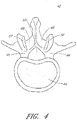
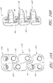
- the vertebral column 2 comprises a series of alternating vertebrae 4 and fibrous discs 6 that provide axial support and movement to the upper portions of the body.
- the vertebral column 2 typically comprises thirty-three vertebrae 4, with seven cervical (C1-C7), twelve thoracic (T1-T12), five lumbar (L1-15), five fused sacral (S1-S5) and four fused coccygeal vertebrae.
- FIGS. 2A and 2B depict a typical thoracic vertebra.
- Each vertebra includes an anterior body 8 with a posterior arch 10.
- the posterior arch 10 comprises two pedicles 12 and two laminae 14 that join posteriorly to form a spinous process 16. Projecting from each side of the posterior arch 10 is a transverse 18, superior 20 and inferior articular process 22.
- the facets 24, 26 of the superior 20 and inferior articular processes 22 form facet joints 28 with the articular processes of the adjacent vertebrae.
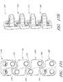
- the typical cervical vertebrae 30, shown in FIG. 3 differ from the other vertebrae with relatively larger spinal canals 32, oval shaped vertebral bodies 34, bifid spinous processes 36 and foramina 38 in their transverse processes 40. These foramina transversaria 38 contain the vertebral artery and vein.
- the first and second cervical vertebrae also further differentiated from the other vertebrae.
- the first cervical vertebra lacks a vertebral body and instead contains an anterior tubercle. Its superior articular facets articulate with the occipital condyles of the skull and are oriented in a roughly parasagittal plane. The cranium is able to slide forward and backwards on this vertebra.
- the second cervical vertebra contains an odontoid process, or dens, which projects superiorly from its body. It articulates with the anterior tubercle of the atlas, forming a pivot joint. Side to side movements of the head occur at this joint.
- the seventh cervical vertebra is sometimes considered atypical since it lacks a bifid spinous process.
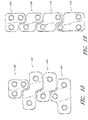
- the typical lumbar vertebrae 42 is distinguishable from the other vertebrae by the absence of foramina transversaria and the absence of facets on the surface of the vertebral body 44.
- the lumbar vertebral bodies 44 are larger than the thoracic vertebral bodies and have thicker pedicles 46 and laminae 48 projecting posteriorly.
- the vertebral foramen 50 is triangular in shape and larger than the foramina in the thoracic spine but smaller than the foramina in the cervical spine.
- the superior 52 and inferior articular processes (not shown) project superiorly and inferiorly from the pedicles, respectively.
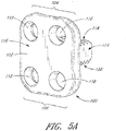
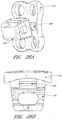
- an interbody vertebral implant 100 is provided.
- the implant 100 comprises a stabilization or fixation plate 102 having an upper portion 104 and a lower portion 106, and a bone facing surface 108 and an access surface 110.
- the bone facing surface 108 will actually contact the vertebral bone surface, but in other embodiments, other structures or components may lie in between the bone facing surface 108 and the bone surface of the vertebra.
- Each upper portion 104 and lower portion 106 has one or more spaces or holes 112 oriented between the bone facing surface 108 and the access surface 110 that are configured to accept screws and/or other attachment devices for anchoring the implant 100 to the vertebral bone.
- One or more spacers or spacing structures 114 are located on the bone facing surface 108 of the fixation plate 102. The spacers 114 are typically integrated with the fixation plate 102 about the bone facing surface 108.
- the spacer may comprise any structure configured to maintain a separation and resist compression between two adjacent vertebral bodies.
- the spacer may have any of a variety of overall shapes, including but not limited to a rectangular box, a trapezoidal box, H-shaped, O-shaped, V-shaped, with or without one or more lumens within the spacing structure.
- the spacer 114 has a base 116, a superior surface 118 and an inferior surface 120, and side surfaces 122,124, and a posterior surface 126.
- Each surface 118, 120, 122, 124, 126 need not be flat, and may be curved or undulating or any combination thereof
- the upper and lower surfaces 118, 20 are configured for facing the superior and inferior vertebral bodies 8 or 34 adjacent to an implantation site.
- the relative configuration of the upper surface 118 and lower surface 120 may vary, depending upon the relative position desired between the two adjacent vertebrae, the anatomical shape of the vertebrae, ease of insertion of the implant and other factors. For example, if a neutral vertical alignment is desired between two vertebrae, the upper and lower surfaces 118, 120 may have generally parallel planar orientations.
- the upper and lower surfaces 118, 20 may have a wedge-like relationship to allow fixation of the vertebrae in the desired non-neutral position.
- a non-neutral alignment with respect to the anterior-posterior direction may also be used to compensate for excessive lordosis or kyphosis in other portions of the vertebral column.
- the height of the spacing structure 116 at any section between the upper and lower surfaces 118, 120 may be further configured to accommodate degenerative changes or anatomical anomalies to provide fixation in the desired relative position.
- the side surfaces 122, 124 of the spacing structure 114 may be generally parallel or skewed.
- the side surfaces 122,124 of the implant 100 taper with increasing distance from the base 116 of the implant 100.
- a tapered spacing structure may facilitate insertion of the implant 100 into the intervertebral space.
- the one or more side surfaces may flare distally or have both tapering and flaring portions.
- FIGS. 5B and 5C is one embodiment comprising a closed-shaped spacer 1.14 with a lumen 128 between the superior and inferior surfaces 118, 120.
- the side surfaces 122, 124 may have a slight taper along the posterior direction.
- FIG. 6 depicts one embodiment with a block spacer 130 that lacks a spacer lumen.
- FIG. 7 depicts another embodiment comprising an H-shaped spacer 132 with two protruding members 134, 136 and one bridge member 138 between the two protruding members 134, 136.
- the bridge member 138 maybe oriented in any of a variety of positions between the two protruding members 134, 136.
- the two protruding members 134, 136 need not have a similar or symmetrical shape. Some embodiments may have more than two protruding members 134, 136 and/or one or more bridge members 138.
- FIGS. 8A and 8B illustrate another embodiment comprising a spacer 140 with two posterior members 142, 144 where each posterior member 142, 144 has a window or hole 146 between the outer side surface 148 and inner side surface 150 of the posterior member.
- This window or hole may allow bony growth into the window or hole and between the two posterior members 142, 144.
- the space 146, 152 within and/or between the posterior members 142, 144 may also be filled with graft materials (not shown).
- the graft material may be an autograft, allograft, xenograft or synthetic material. Synthetic graft material may be ceramic-based, silicon-based or calcium-based.
- the graft material may also include osteoinductive factors to promote bone ingrowth.
- synthetic graft materials and constituents that may be used between or about the hyoid bone segments.
- One or more surfaces of the implant may also have surface projections, indentations, or holes or pores that can further alter the characteristics of the implant.
- angled projections, barbs, teeth 154 or ramped surfaces which incline outwardly from one or more spacer surfaces toward the fixation plate 102 may be provided on one or more surfaces that allow insertion of the spacing structure in one direction but resist movement in the opposite direction.
- These teeth 154 may be advantageous in reducing the migration of the device out of the intervertebral space.
- Improved fixation of the spacer 156 may maintain device position during drilling of the screw holes into the vertebral bodies, and may also reduce the forces acting upon the screws or other retaining structures, thereby reducing the risk of backout.
- the teeth 154 are preferably provided on the superior and/or inferior surfaces 118, 120 of the spacer 156, but other surfaces may also have teeth or other tissue engagement structures.
- the tissue engagement structures may be combined with indentations, holes or pores for allowing bony ingrowth or filling with bony matrix or graft materials as previously described. These holes may be utilized with other surface features to further enhance insertion and stabilization of the implant.
- the spacer has a height of about 4 mum to about 50 mm, or preferably about 4 mm to about 12 mm. Occasionally, the spacer has a height of about 6 mm to about 9 mm. In some embodiments, the spacer has a length along the AP axis, as measured from the bone facing surface of the fixation plate to the most posterior end of the spacer, of about 5 mm to about 25 mm. In some embodiments, the spacer length is about 10 mm to about 15 mm. The width of the spacer is generally about 5 mm to about 25 mm, and in some situations, about 10 mm to about 15 mm. One skilled in the art can dimension the spacer based upon the implantation location and specific vertebral morphology, neurological anatomy and disease state.
- the spinal fusion implant may include, be made of, treated, coated, filled, used in combination with, or contain artificial or naturally occurring materials suitable for implantation in the human spine. These materials include any source of osteogenesis, bone grawth-promoting materials, bone derived substances, bone morphogenetic proteins, hydroxyapatite, genes coding for the production of bone, and bone including, but not limited to, cortical bone.
- the implant can also be formed of material such as metal including, but not limited to, titanium and its alloys, surgical grade plastics, plastic composites, ceramics, or other materials suitable for use as a spinal fusion implant.
- the device comprises a radiolucent material, a radio-opaque material, or a combination thereof.
- a device that is partially or completely radiolucent may be advantageous when evaluating the effect of the implant post-implantation.
- Many existing spinal fixation plates and/or spacers obscure visualization of the vertebrae, which can complicate post-operative treatment, diagnosis and prognosis of the patient's condition.
- the implant may include at least in part materials that are bioabsorbable in the body.
- the implant of the present invention can be formed of a porous material or can be formed of a material that intrinsically participates in the growth of bone from one of adjacent vertebral bodies to the other of adjacent vertebral bodies.
- the implant may be treated with, coated with, or used in combination with substances to inhibit scar tissue formation.
- the implant of the present invention may be modified, or used in combination with materials to provide antibacterial properties, such as, but not limited to, electroplating or plasma spraying with silver ions or other substance.
- the implant may optionally comprise an electrical source to provide ionophoresis of the silver ions into the surrounding tissue to prevent infection.
- the antibacterial properties may include bactericidal and/or bacteriostatic characteristics. Similarly, anti-fungal characteristics may also be provided. Any of these materials as appropriate may be used at any time after the implant(s) are inserted.
- the fixation plate may have a generally flat configuration, curved configuration or combination thereof.
- each surface of the fixation plate may also have a generally flat or curved configuration or combination thereof.
- Each surface of the fixation plate need not have the same configuration.
- the edges of the fixation plate may optionally be rounded, smoothed or polished.
- the flange is dimensioned such that flange extends about 2 mm beyond the edges of the base of the spacer.
- the fixation component is dimensioned to extend generally about 1 mm to about 20 mm beyond the cross sectional border of the spacer component at its interface with the fixation plate.
- the flange may extend by 3 mm or 4 mm or more beyond the spacer base.
- the flange may or may not extend uniformly along the spacer edges.
- the shape of the flange may be different from the shape of the spacer base.
- the average thickness of the fixation plate is within the range of about 1 mm to about 5 mm. In other embodiments, the average thickness of the fixation plate is within the range of about 1.5 mm to about 3.0 mm. The thicknesses of the fixation plate need not to be uniform. In one embodiment, the fixation plate is conformable to the vertebral surfaces of the implantation sites.
- the spacer component is attached to a fixation component comprising a mesh or lattice.
- the fixation component may also be made from a material that is the same or different from the spacer component.
- a fixation component and a spacer component having different materials may be beneficial because the spacer component may be configured to withstand compressive forces while the fixation component is configured to withstand primarily tension forces.
- the fixation component may comprise a polymer, a woven material, or a combination thereof.
- each upper portion and lower portion of the fixation plate 102 has one or more spaces or holes 112 oriented between the bone facing surface 108 and access surface 110 that are configured to accept screws and/or other attachment elements for anchoring the implant to the vertebral bone.
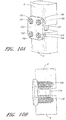
- one or more bone screws 158 configured for insertion through one or more screw holes 112 in the fixation plate 102 are provided.
- each bone screw 158 typically comprises a screw head 160 and a screw body 162. The bone screws 158 and/or anchors may or may not be self-tapping.
- the invention further comprises bone anchors comprising an anchor head and an anchor body.
- the anchor head is adapted to interface with the fixation plate to hold the fixation plate against the adjacent vertebral bone structures.
- the anchor body comprises threads or barbs for piercing or inserting into bone and fixing the position of the anchor head.
- the anchor body may or may not form an interface with the holes of the fixation plate to further fix the position of the fixation plate with respect to the vertebral bone.
- Batch hole 112 of the flange or fixation plate 102 need not have the same configuration or size.
- the holes 112 are typically round in cross section and dimensioned to allow passage of a screw body 162 therethrough while resisting passage of the screw head 160 completely through the hole 112. In other embodiments, however, at least a portion of the hole 112 may have a non-round cross-section, such as an oval, square, rectangle, polygonal or other closed shape.
- the inside surface of the holes 112 may be covered with a lubricious coating to facilitate insertion and/or movement of a screw or other attachment device through the hole.
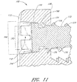
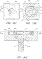
- each hole FIG. 11 depicted in each hole FIG. 11 , comprises a first inside surface 164 adjacent to the access surface 110 having a first diameter 166, and a second inside surface 168 adjacent to the bone facing surface 108 having a second diameter 170.
- first inside surface 164 and second inside surfaces 168 may be dimensioned to augn a corresponding screw 172 in generally one particular orientation.
- the second inside surface 168 of a screw hole 112 comprises threads 174 and adapted to form a rotatable mechanical interfit with threads 176 on a corresponding screw 172 inserted through the hole 112.
- the first inside surface 164 of the screw hole 112 may also be similarly threaded, or may be configured to accept the head 178 of a screw 172 inserted through the hole 112 to allow flush positioning or recessed positioning of the screw head 178 with the access surface 110 of the fixation plate 102.
- the bone anchor or screw 172 for the particular flange hole 112 is typically selected so that the largest diameter of the screw or anchor head 178 is larger than the second diameter 170 of the hole 112.
- the largest diameter of the screw or anchor head 178 may be larger than the first diameter 166.
- the largest diameter of the screw or anchor head 178 is between the first diameter 166 and the second diameter 170.
- the flange holes 112 may have a first diameter 166 of about 3 mm to about 10 mm, and in other embodiments, may have a diameter of about 4 mm to about 6 mm.
- the flange holes 112 may have a second diameter 170 of about 0.1 mm to about 4.0 mm smaller than the first diameter, and in one embodiment, may have a second diameter 170 of about 0.2 mm to about 1.0 mm smaller than the first diameter 166, or even about 0.2 mm to about 0.4 mm smaller than the first diameter 166.
- the screw head or anchor head 178 may have a diameter of about 3.2 mm to about 10.2 mm, and in one embodiment, may have a diameter of about 4.4 mm to about 6.4 mm.
- the recessed positioning may be partial or complete. With partial recessed positioning, only a portion of an inserted screw lies below the access surface 112 of the fixation plate 102, while with complete recessed positioning, all the screw head 178 may lie at or below the access surface 112 of the fixation plate 102.
- the screw hole 112 about the first inside surface 164 can have any of a variety of cross sectional shapes.
- the one or more holes are configured to align a screw 172 having a general perpendicular orientation with respect to either or both the access surface 110 or bone facing surface 108 of the flange 102.
- one or more holes 112 may be configured to align a screw in a skewed orientation.
- the skewed orientation may have a slight superior or inferior angle, depending upon whether the hole is located on the upper portion or lower portion of the flange, respectively.
- a skewed orientation in the superior/inferior direction may reduce the risk that the screw 172 remains secure in the vertebral body by providing sufficient bone structure between the screw body and the intervertebral space.
- a screw hole 112 is configured to accept a screw 172 in an orientation that is within the range of about 0 degrees to about 60 degrees superiorly with respect to the plane between the two corresponding vertebrae. In one embodiment, the screw hole is configured to accept a screw 172 in an orientation that is within the range of about 5 degrees to about 30 degrees superiorly, and in some embodiments, to accept a screw 172 in an orientation that is within the range of about 10 degrees to about 20 degrees superiorly. In one embodiment, a screw hole 172 is configured to accept a screw 172 in an orientation that is within the range of about 0 degrees to about 60 degrees inferiorly with respect to the transverse plane between the two corresponding vertebrae 4.
- the screw hole 112 is configured to accept a screw 172 in an orientation that is within the range of about 5 degrees to about 30 degrees inferiorly, and in some embodiments, to accept a screw 172 in an orientation that is within the range of about 10 degrees to about 20 degrees inferiorly.
- the particular orientation of a screw hole 112 may be determined by the dimensions of the screw 172 used with the device and the vertebrae 4 to which the device is to be attached.
- One or more holes 112 of the flange 102 may also be configured to a skewed angle in the medial/lateral direction.
- the hole 112 may be configured with a medially directed screw orientation to avoid insertion of a screw through the outer surface of the vertebral body or through a pedicle, but a lateral screw orientation may also be used.
- Screw holes 112 located medially on the flange 102 may have a lateral orientation.
- a screw hole 112 is configured to accept a screw 172 in an orientation that is within the range of about 0 degrees to about 45 degrees medially with respect to the sagittal plane through a vertebra 4.
- the screw hole 112 is configured to accept a screw 172 in an orientation that is within the range of about 5 degrees to about 30 degrees medially, and in some embodiments, to accept a screw 172 in an orientation that is within the range of about 10 degrees to about 20 degrees medially. In one embodiment, a screw hole 112 is configured to accept a screw 172 in an orientation that is within the range of about 0 degrees to about 45 degrees lateral with respect to the sagittal plane through the vertebrae 4. In one embodiment, the screw hole is configured to accept a screw 172 in an orientation that is within the range of about 5 degrees to about 30 degrees laterally, and in some embodiments, to accept a screw 172 in an orientation that is within the range of about 10 degrees to about 20 degrees laterally.
- first and second inside surfaces 165, 168 may be threaded and capable of forming a rotatable interfit with the threads of a corresponding screw 172 or other attachment device.
- One or more holes 112 of the flange 102 may also be configured to accept and/or orient the tip of a corresponding drill guide so that screw holes in the vertebrae 4 may be created after the device has been positioned at its implantation site. By drilling screw holes into the vertebrae 4 after the positioning of the device, the risk of misaligned vertebral screw holes and flange holes 112 may be reduced. Misalignment may result in an ill-fitting and unstable implant.
- one or more screw holes of the fixation plate or flange may be configured to allow a range of corresponding screw orientations when the screw is inserted through the screw hole.
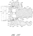
- a polyaxial screw hole 180 wherein at least a portion of the inner surface 182 of the polyaxial screw hole 180 having a concave surface 184 that is capable of accepting a range of screw orientations within the screw hole 180.
- the concave surface 184 typically comprises an entire circumference of the inner surface of the screw hole 180, but in some embodiments, may comprise only one or more portions of a screw hole 180 circumference.
- Concave surfaces along limited portions of a circumference may allow pivoting or a range of movement along one axis of the screw hole 180 while limiting the pivoting along another axis of the screw hole 180.
- the distal surface 188 of the screw head 190 may be configured with a convexity complimentary to the concave surface 184 of the screw hole 180.
- a screw hole 180 is configured to provide a screw orientation range of about 0 degrees to about 60 degrees from the central axis of the screw hole. In one embodiment, the screw hole 180 is configured to provide a screw orientation range up to about 5 degrees to about 30 degrees from the central axis of the screw hole, and in some embodiments, to provide a screw orientation range up to about 10 degrees to about 20 degrees. In one embodiment, a screw hole 180 is configured to provide a screw orientation range of about 0 degrees to about 60 degrees superiorly with respect to the plane between the two corresponding vertebrae 4.
- the screw hole 180 is configured to provide a screw orientation range of about 5 degrees to about 30 degrees superiorly, and in some embodiments, to provide a screw orientation range of about 10 degrees to about 20 degrees superiorly. In one embodiment, a screw hole 180 is configured to provide a screw orientation range of about 0 degrees to about 60 degrees inferiorly with respect to the transverse plane between the two corresponding vertebrae. In one embodiment, the screw hole 180 is configured to provide a screw orientation range of about 5 degrees to about 30 degrees inferiorly, and in some embodiments, to provide a screw orientation range of about 10 degrees to about 20 degrees inferiorly. The particular orientation of a screw hole may be determined by the dimensions of the screw 186 used with the device and the vertebrae 4 for which the device is to be attached.
- One or more holes 180 of the flange 102 may also be configured to a skewed angle in the medial/lateral orientation.
- the hole 180 may be configured with a medially directed screw orientation to avoid insertion of a screw 186 through the outer surface of the vertebral body 8 or through a pedicle 12, but a lateral screw orientation may also be used.
- a screw hole is configured to provide a screw orientation range of about 0 degrees to about 45 degrees medially with respect to the sagittal plane through a vertebra.
- the screw hole is configured to provide a screw orientation range of about 5 degrees to about 30 degrees medially, and in some embodiments, to provide a screw orientation range of about 10 degrees to about 20 degrees medially.
- a screw hole is configured to provide a screw orientation range of about 0 degrees to about 45 degrees lateral with respect to the sagittal plane through the vertebra. In one embodiment, the screw hole is configured to provide a screw orientation range of about 5 degrees to about 30 degrees laterally, and in some embodiments, to provide a screw orientation range of about 10 degrees to about 20 degrees laterally.
- the screw holes 164 in the upper portion of the flange 102 may be configured in the vertical axis to allow an insertion angle of about +30 degrees to about - 15 degrees.
- the screw holes 164 in the lower portion of the flange 102 may be configured to provide an insertion range of about +20 degrees to about -5 degrees in the vertical axis.
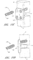
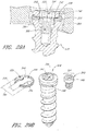
- FIGS. 10C and 10D shows the use of the implant in FIGS. 10A and 10B with at least one screw 158 inserted through an upper screw hole 164 of the implant and into the upper vertebral body of an intervertebral space with a superiorly angled orientation. In some instances, this screw orientation may reduce the risk of bone fracture into the intervertebral space with or without migration of the screw body into the same space.
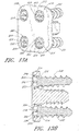
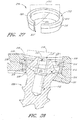
- FIGS. 13A through 13C depict one embodiment of the invention comprising an expandable/collapsible retainer ring or collar 200.
- the retainer ring/collar 200 allows insertion of a corresponding screw 202 in one direction through a screw hole 204 but resists movement of the screw 202 in the opposite direction.
- the retainer ring/collar 200 may be positioned within one or more screw holes 204 with a recess or indentation 206 along at least a portion of its circumference capable of accepting at least the outside diameter portion of the retainer ring/collar 200.
- the recess or indentation 206 typically comprises a circumferential channel of the flange hole 204 having a recess diameter 208 that greater than the first diameter 210 of the flange hole 204.
- the recess or indentation 208 is typically located closer to the access surface 110 of the fixation plate 102, rather than the bone facing surface 108, but may also be located at other positions within the screw hole 204.
- the ring or collar 200 has an outside retainer diameter 212 and an inside retainer diameter 214, a first surface 216 between the outside retainer diameter 212 and inside retainer diameter 214 closer to the access surface 110 of the fixation plate 102 and a second surface 218 between the outside retainer diameter 212 and inside retainer diameter 214 closer to the bone facing surface 108 of the fixation plate. Changes in the inside retainer diameter of the retainer may or may not alter the outside retainer diameter of the retainer, and vice versa.
- the retainer ring or collar has a completely closed configuration, but in other embodiments, as shown in FIGS. 13A to 13C , the ring or collar 200 has an interrupted configuration comprising two ends 220, 222 about an expansion space 224.
- the retainer ring/collar 200 is capable of radial expansion and collapse by altering the distance between the two ends 220, 22.
- the retainer ring 200 is configured to resiliently collapse such that the outside retainer diameter 212 is less than the first diameter 166 of the flange hole 204 so that the retainer ring may be passed into the flange hole recess 206.
- the retainer ring 200 can then re-expand its outer retainer diameter 212 to at least partially occupy the flange hole recess 206.
- the retainer ring 200 is further configured to resiliently expand its inside retainer diameter 214 to allow passage of a screw or anchor head 226 through the retainer ring/collar 200. Expansion of the inside retainer diameter 214 may or may not result in expansion of the outside retainer diameter 212 to occupy additional space within the flange hole recess.
- the retainer ring/collar comprises a compressible or reformable material such that the inside retainer diameter can be increased without requiring increase in the outside retainer diameter.
- the retainer ring/collar 200 By configuring the retainer ring/collar 200 to resiliently deform when the screw or anchor head 226 is passed through the retainer ring/collar 200 with an increased force, the retainer ring/collar 200 can resist backout of the screw 202 or anchor where the blackout forces acting on the screw 202 or anchor are insufficient to cause ring/collar 200 expansion and allow movement of the screw 202 or anchor.
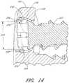
- the force required to blackout the screw or anchor may be increased relative to the force required to pass the screw or anchor through the retaining ring/collar by providing a ramped surface about the retaining ring/collar and/or the screw or anchor head.
- a surface 228 about the inside retainer diameter 214 of a ring/collar 230 that is ramped or inclined radially inward toward the bone contact surface 108 of the fixation plate 102 may facilitate the insertion of the screw 202 or anchor through the retainer ring/collar while providing a larger second surface 232 of the screw or anchor to resist blackout.
- a screw or anchor head may also have a ramped or inclined surface radially outward from the screw body that may facilitate insertion of the screw or anchor through the retainer ring/collar while providing a larger screw or anchor head surface area to resist blackout.
- the cross sectional shape of the retainer structure may be any of a variety shapes, including a circle, oval, squares, rectangles, polygonal or other closed shape.
- the cross sectional shape of the retainer may vary along the length of the retainer.
- the cross sectional shape of the screw hole indentations may also be any of a variety of shapes, including a circle, oval, squares, rectangles, polygonal or other closed shape.
- the cross sectional shape of the retainer along the outside diameter may or may not be similar to the cross sectional shape of the screw hole circumferential indentation or recess.
- the implant further comprises an flange hole insert 234 that provides an intermediate layer of material between the screw or anchor head 226 and the inner surface 236 of the flange hole 204.
- the insert 234 may comprise a generally polymer, metallic, or ceramic member comprising an outer flange hole contacting surface 238 and an inner anchor contacting surface 240, where the outer flange hole contacting surface 238 is shaped to conform to at least a portion about the inner surface 236 of the flange hole 204.
- the anchor contacting surface 240 may or may not conform to at least a portion of the screw or anchor head surface 242.
- the flange hole insert 234 is capable of absorbing wear forces transmitted between the fixation plate 102 and the screw 204 or anchor. Absorption of the forces between these two components of the implant may reduce the risk of implant failure and/or loosening that occurs at the interface between the two components.
- the flanged interbody device comprises a polyaryl polymer, including but not limited to PEK, PEEK, PEKK, PEKEKK or a blend thereof, and the insert comprises a titanium or titanium alloy. Other combination may also be used as is known by those with skill in the art.
- the flange is configured for positioning across an intervertebral space such that the upper portion of the flange is adapted to contact the superior vertebra and the lower portion of the flange is adapted to contact the inferior vertebra about an intervertebral space.
- the flange may be configured to contact a single vertebra about an intervertebral space, or more than two vertebrae. In some embodiments, the flange may span two or more intervertebral spaces.
- the implant is adapted for positioning about the anterior surface of the vertebrae, along the anterior surfaces of vertebral bodies.
- the flange of the implant may also be configured to contact other vertebral structures such as the pedicles, transverse processes, facet joints, superior and inferior articular processes and spinous processes.
- the implant is configured to attach to these vertebral structures without attaching or contacting the vertebral bodies.
- the flange 102 of implant 100 has a general square or rectangular shape and is dimensioned to allow stable attachment of the implant 100 to the adjacent vertebral bodies 8.
- the corners where any two sides of the flange meet may be angled, rounded or curved.
- the flanged implant 100 depicted in FIGS. 5A through 5C comprises rounded corners,
- the flange 102 may comprise any of a variety of other shapes, including trapezoids, circles, ovals, polygons or other closed shapes.
- the flange 102 may or may not have a symmetrical configuration with respect the upper and lower portions and/or the left and right portions of the flange.
- the shape and/or dimensions of the flange may or may not allow implantation of the additional implants at adjacent intervertebral spaces.
- the flange 244 of one implant 246 is configured and dimensioned to form a complimentary shape with a corresponding adjacent implant and/or to prevent overlap or mechanical interference with an adjacent implant 248.
- the complementary fit between two adjacent implants may be loose or tight.
- the interface between the corresponding flanges may be non-overlapping as depicted in FIGS. 15A and 15B , or overlapping, as shown in FIGS. 25A and 25B .
- the complementary flanges may be asymmetric or symmetric with respect to the left and right portions of the flanges, and/or the upper and lower portions.
- the flange may be configured such that the vertical orientation of the flange, whether used right-side up or upside-down, does not affect the complimentary interfacing with adjacent flanges.
- FIGS. 15A and 15B depict one embodiment comprising an implant system with a superior implant and an inferior implant.
- the inferior portion 252 of the superior implant flange 244 has a right-sided asymmetry that is complementary to the corresponding left-sided asymmetry of the superior portion 254 of the inferior implant flange 250.
- the complementary-shaped flanges allow implantation of the superior flange and inferior flange at adjacent intervertebral spaces that would not otherwise allow implantation of traditionally shaped fixation plates.
- the left/right asymmetry of each implant in the fixation system may be opposite.
- the superior implant 246 and flange 244 is identical to inferior implant 248 and flange 250 but is rotated 180 degrees.
- the fixation system may further comprise one or more middle flange implants 256, a superior end flange implant 246 and/or an inferior end flange implant 248.
- the superior flange implant 246 and inferior flange implant 248 may have configurations and/or dimensions that have a greater surface area than the middle flange implants because there is only one implant, rather than two, adjacent to each of the end implants. This may provide and utilize the greater stability and securement available at the end implants 246, 248 compared to the middle implants 256.
- the inferior portion 252 of the superior flange implant 246 may have a right-sided asymmetry that is complementary to the corresponding left-sided asymmetry of the superior portion 258 of the middle implant flange 256.
- the inferior portion 260 of the middle flange 256 implant flange may have a right-sided asymmetry that is complementary to the corresponding left-.sided asymmetry of the superior portion 254 of the inferior flange implant 248.
- the complementary-shaped flanges allow implantation of the superior, middle and inferior flanges at sequential intervertebral spaces that would not otherwise allow implantation of traditionally shaped fixation plates.
- each middle flange implant 256 is provided.
- the flange of each middle implant 256 is configured similarly, such that the superior portion 258 of each middle flange implant 256 is complementary to the inferior portion 260 of each middle flange implant 256, as well as the inferior portion 252 of superior flange implant 246.
- a fixation system with serial implants of different widths is provided.
- each implant comprises a left/right complementary configuration as previously described, but implants 256, 262, 264 and 266 having different left/right widths are provided.
- the different widths do not interfere with the complementary configurations of the implants 256, 62, 264, 266 in the fixation system.
- Having implants with different widths allow the selection of differently dimensioned implants as the size of the vertebrae change along a sequential length of the vertebral column.
- the different widths of implants need not increase or decrease incrementally along the implantation sequence and may also allow tailoring of a particular implant to a particular vertebral anatomy along a sequence of vertebral implants.
- the differences in width of each implant need not be symmetrical with respect to the left and right sides. Spacers of different left/right widths may also be provided. Spacer size need not correlate with changes in flange size or configuration.
- implants 256, 268, 270, 272 of different heights may also be provided in some embodiments to compensate for changes in size of lower vertebrae and/or pathological changes in height. Implants of different heights may also have different widths.
- each implant 268 of the fixation system has a superior flange portion that is complementary with the inferior flange portion of each implant without particular superior end and inferior end implants.
- FIGS. 21 through 23 depict embodiments where the superior and inferior portions of each implant flange in the fixation system are not complementary in a left/right manner, but each implant flange overall is complementary in a left/right manner.
- FIG. 21 depicts a three implant fixation system comprising a right-sided superior implant 274, a left-sided middle implant 276, and a right-sided inferior implant 278.
- FIG. 22 depicts a four implant fixation system comprising a right-sided superior implant 274, a left-sided middle implant 276, and a right-sided middle implant 278 and a left-sided inferior implant 278.
- the left-sided middle implant 276 and right-sided middle implant 278 differs only by a 180-degree rotation.
- FIG. 21 depicts a three implant fixation system comprising a right-sided superior implant 274, a left-sided middle implant 276, and a right-sided inferior implant 278.
- FIG. 22 depicts a four implant fixation system comprising a right-sided superior implant 274,
- FIG. 23 represents a five implant fixation system comprising a left-sided superior implant 274, two right-sided middle implants 276, one left-sided middle implant 278 and a right-sided inferior implant 248. Likewise, six or more implants may be similarly configured and sequentially implanted.
- FIGS. 24 and 25A and 25B depict embodiments where the flange is configured to allow sequential implantation along the vertebral column but the flange and flange holes maintain a left/right symmetry. In one embodiment, it is hypothesized that maintaining left/right symmetry may reduce the torsional strain or stress acting upon the implants relative to the symmetric implants described elsewhere in this application. Flanges with left/right symmetry, however, are not bound by this theory.
- FIG. 24 depicts one embodiment where the upper portions 280, 282 of the middle and inferior implant flanges 284, 286 have a bilateral configuration while the inferior portions 288, 290 of the middle and superior implant flanges 284 have a medial configuration. Although the embodiment shown in FIG. 24 comprises a superior end and inferior end implants 292, 286, neither implant 292, 286 is necessary for the invention.
- FIGS. 25A and 25B illustrate one embodiment comprising implants 294, 296, 298 with complementary overlapping flange shapes.
- the superior portions 300, 302 of the middle and inferior implants 296, 298 have an anterior configuration while the inferior portions 304, 306 of the middle and superior implants 296,294 have a posterior orientation.
- the patient is intubated and general anesthesia is achieved.
- the patient is prepped and draped in the usual sterile fashion.
- An anterior approach to the spine is used to expose the anterior vertebral bodies. Many anterior approaches to the vertebral column are described in various medical texts such as Campbell's Operative Orthopaedics, 10th ed., edited by Canale et al., pp. 1569 - 1588 , herein incorporated by reference.
- the upper cervical spine is accessed.
- the anterior upper cervical spine may by a transoral or retropharyngeal route, or by using a subtotal or extended maxillotomy.
- the lower cervical spine, cervicothoracic junction, thoracic spine, thoracolumbar junction, lumbar region, lumbosacral junction, sacrum or combination of the above regions are accessed.
- the intervertebral space is debrided.
- the flanged interbody implant is optionally packed with natural or artificial bone matrix and/or other osteogenesis factors and inserted into the intervertebral space.
- the flange is positioned against the anterior cervical vertebral bodies and attached with screws or anchors.
- the operative site is irrigated with antibiotics and the operative field is sutured closed.
- the vertebral column is accessed and one or more intervertebral spaces are identified and accessed. In some embodiments, two or more intervertebral spaces are accessed, and in still other embodiments, two or more adjacent intervertebral spaces are accessed.
- the operative site is rinsed with antibiotic solution and the operative field is closed in layers.
- Another embodiment comprises the steps of providing an intervertebral implant system comprising a first fixation plate and first spacer and a second fixation plate and spacer, wherein the lower portion of the first fixation plate has a complementary shape to a corresponding complementary shape at the upper portion of the second fixation plate.
- the interbody spacer and the fixation plate are configured to provide some degree of relative movement between each other.
- the device may have improved securement to osseous structures with improved conformance to the existing anatomy at the site of implantation.
- FIGS. 26A through 26D depict one such embodiment, comprising a hinge joint 308 oriented to allow pivoting in the sagittal plane.
- the hinge joint 308 may be oriented to allow pivoting in other planes such as the transverse plane, coronal plane, or any plane in between the three planes.
- the joint provided between the interbody spacer 114 and the fixation plate 102 may be further configured to limit the range of movement provided.
- the configuration of the interbody spacer 114 and/or fixation plate 102 may restrict the relative range of motion between the two components. Recesses in the fixation plate 102 or a size reduction or tapering of the interbody spacer component 114 about the movement joint 308 may allow greater movement.
- the movement joint 308 may be configured to vary other characteristics of the movement joint, including frictional resistance or ratchet-type resistance to movement.
- fixation plate 102 and movement joint 308 are depicted, other embodiments will have two or more movement joints 308 and wherein either the fixation plate 102 and/or interbody spacer 114 may have a split configuration so that each split component has its own movement joint 308 and can independently move or pivot to provide additional conformance to the existing anatomy.
- the fixation plate 102 and/or interbody spacer 114 may be configured with two or more subcomponents that are provided with an intracomponent hinge or movement joint to provide better conformance of the device to the existing anatomy.
- the fixation plate component of the device may be configured as left and right subcomponents with a hinge joint in between.
- the interbody spacer may have superior and inferior subcomponents with a hinge joint therebetween to allow pivoting of the superior and inferior surfaces of the interbody spacer.
- the superior and inferior surfaces of the interbody spacer may pivot laterally or in an anterior-posterior direction, or any direction in between.
- FIGS. 26A to 26D Although a hinge-type movement joint is depicted in FIGS. 26A to 26D , other types of joints or connections between the interbody spacer component and fixation plate are also contemplated, including but not limited to a ball-and-socket joint or one or more metallic cords embedded or attached between me nxanon plate and interbody spacer to allow limited polyaxial movement.
- screw retaining assemblies are also contemplated and may be used with the interbody fusion devices previously described.
- the other screw retaining assemblies described below may also be used with other types of orthopedic and medical devices, as well as non-medical applications, including but not limited to construction, home improvement, consumer appliance, electronic device and other applications.
- FIGS. 27 and 28 depict an alternative embodiment comprising an expandable fastener retaining ring 310 residing partially within an expansion groove 312 of a fastener lumen 112 and partially within the fastener lumen 112 itself.
- the retaining ring 310 has a reduced configuration and an expanded configuration but is biased to the reduced configuration.
- the retaining ring 310 has a retaining segment 314 and a pivot segment 316. Referring to FIG. 28 , the retaining segment 314 has an enlarged outer diameter that is adapted to fit in an expansion groove 312. In the expanded configuration of the retaining ring 310, the retaining segment 314 further expands into the expansion groove 312, thereby increasing the inner diameter 318 of the retaining segment 314.
- the inner diameter 318 of the retaining segment 318 has a sloped inner surface 320 that narrows from the proximal opening 322 of the retaining ring 310.
- the sloped surface 320 facilitates expansion of the retaining segment 314 as a fastener 158 is inserted through it.
- fastener head 160 If backout forces are exerted on the fastener head 160, the fastener head 160 will abut a generally perpendicular retaining surface 232 located at the transition from the inner diameters 318, 324 of the retaining and polyaxial segments 314, 316 of the ring 310 and will resist fastener head 160 backout.
- the polyaxial segment 316 of the retaining ring 310 comprises a sloping reduced diameter 326 towards the distal opening 328 of the retaining ring310, such that the smallest diameter of the polyaxial segment 316 is smaller than the largest diameter of the fastener head 160 and prevents or resists the fastener head 160 from passing completely through the retaining ring 310.
- the slope of the cross-section through the retaining ring may be linear, curved, toothed or jagged or any other sloped surface.
- the fastener 330 comprises a secondary screw 332 and screw lumen 334 within the fastener head 336.
- An expandable ring 338 or disc having a reduced and an expanded configuration, is provided within a groove 340 about the fastener head 336, with the expandable ring or disc biased to the reduced configuration.
- the groove 340 is contiguous with screw lumen 334 of the fastener head 336 at one or more openings 342, such that the portion 344 of the inner surface 346 of the expandable ring 338 or disc partially protrudes into the screw lumen 334 when the expandable ring 338 or disc is in the reduced configuration.
- the secondary screw 332 of the fastener 330 has an expansion section, typically the head 348 of the secondary screw 332, which has an outer diameter 350 that is greater than the distance 352 within the screw lumen 334 where the expansion ring 338 or disc protrudes into the screw lumen 334.
- the expansion section 348 of the secondary screw 332 is not in contact with the inner protruding portions 344 of the expandable ring 338 or disc, the expandable ring 338 or disc is able to remain in the reduced configuration.
- the expansion section 348 of the secondary screw 332 When the expansion section 348 of the secondary screw 332 is fully positioned against the protruding portions 344 of the expandable ring 338 or disc, it acts against the expandable ring 338 or disc and causes the expandable ring 338 or disc to enlarge to its expanded configuration.
- the outer diameter 354 of the expandable ring 338 or disc In the expanded configuration, the outer diameter 354 of the expandable ring 338 or disc is greater than the largest outer diameter of the remaining portions of the fastener 330.
- the outer diameter of expandable ring or disc may or may not radially extend from out of the groove.
- the fastener 330 is preferably used in devices having one or more fastener lumens 356 with a proximal diameter 358, middle diameter 360 and distal diameter 362, wherein the proximal diameter 358 is greater than the distal diameter 362 but less than the middle diameter 360, and wherein the proximal diameter 358 is less than the outer diameter 364 of the expandable ring 354 or disc in the reduced configuration.
- the outer diameter of the expandable ring 338 or disc, in the expanded configuration is larger than the proximal diameter 358 of the fastener lumen 356, thereby preventing or resisting blackout of the fastener 330.
- the screw lumen may be lined by an hole insert 366 having a similar relationship of its proximal, middle and distal diameters.
- a hole insert 366 may be preferred, for example, when the orthopedic device utilizing the fastener system comprises a material that may exhibit wear from the metallic fasteners.
- a hole insert 366 may be provided to protect against such wear.
- the screw lumen 334 of the fastener 330 typically but is not required to extend distally from the openings 342 contiguous with the fastener head groove 340 to allow the secondary screw 332 to completely reside within the screw lumen 334 in a position distal to the screw lumen openings 342 and inner protrusions 344 of the expandable ring 338 or disc. This allows the fastener 330 to be attached to the desired structure without having to later insert the secondary screw 332 into the fastener 330 to enlarge the expandable ring 338 or disc.
- the secondary screw 332 need only be moved proximally in the screw lumen 334 to act against the expandable ring 338 or disc and enlarge the expandable ring 338 or disc to its expanded configuration and to retain the fastener in place.
- the use of fastener 330 in cramped or limited access areas such as the attachment of a cervical fusion plate or interbody fusion device, need not attempt to maintain a tiny secondary screw 332 on the end of an attachment device while attempting to align the tiny secondary screw 332 with the screw lumen 334 of the fastener head.
- the user of the fastener 330 only has to align the screwdriver of the secondary screw to the secondary screw in order to manipulate it.
- the screw retaining assembly comprises a biased blocking body residing in an access space about a fastener lumen.
- the blocking body 368 comprises a structure with a fixed opening 370 sized to allow passage of a fastener 158.
- the blocking body 368 further comprises one or more bias members 372 that are biased to an uncompressed configuration in FIG. 30A , but wherein the bias may be overcome to move the bias members 372 to a compressed configuration as in FIG. 30B .
- FIG. 31 illustrates the blocking body 368 in FIGS. 30A and 30B located about a fastener lumen 112 in the uncompressed configuration. In FIGS.
- the blocking body 368 has a first position within an access space 374 that allows passage of a fastener body 162 through the opening 370 in the blocking body 368.
- the opening 370 of the blocking body 368 preferably has a narrowing sloped surface 376 from its proximal face 378 toward its distal face 380 to facilitate the displacement of the blocking body 368 to its compressed configuration as the fastener head 160 is inserted into the opening 370 of the blocking body 368
- FIGS. 33A to 33C illustrate a second position of the blocking body 368 within the access space 374 that prevents or resists passage of the fastener head 160 past the blocking body 368.
- FIGS. 30A to 33C illustrate a blocking body 368 comprising a generally looped structure
- the blocking body may be a partial loop, or any other shaped structure configured to protrude into the fastener lumen 112 or passageway in an uncompressed configuration and not protrude into the fastener lumen 112 or passageway in the compressed configuration.
- the blocking body 368 need not be curved or looped.
- the bias structures used to bias the blocking body to its second position need not be attached to the blocking body. Instead, the bias structures may be attached to one of more surfaces of the access space, or reside in the access space but is not attached to any structure.
- the access space may contain a separate blocking body and bias structure, such as a helical or leaf spring, that exerts an expansion force between a surface of the access space and blocking body to bias the blocking body in the second position.
- some embodiments of the flanged interbody fusion device 382 may comprise locking plates 384 that may be attached to the fixation plate 102 to overlie at least portion of one or more bone screws 158 or fastener heads 160 to prevent or resist backout.
- FIGS. 34A and 34B represent one embodiment with an X-shaped locking plate 384 attachable to the fixation plate 102 using a fastener 386.
- Other locking plate configurations may also be used, depending on the particular arrangement and number of the bone screws used to fasten the device to the bone. As shown in FIG.
- the locking plate 384 may comprise one or more alignment structures 388 that prevent the locking plate 384 from spinning as the fastener 386, typically a screw, is rotated to engage the locking plate 384 to the fixation plate 102.
- the alignment structures typically but not necessarily will interface with complementary structures on the fixation plate 102.
- a fastener may not be required as the alignment structures or other portions of the fastener may form a snap fit with the fixation plate 102.
- more than one locking plate 390 may be used.
- the locking plates 392 may be angled or otherwise shaped for a particular fixation plate configuration.
Landscapes
- Health & Medical Sciences (AREA)
- Orthopedic Medicine & Surgery (AREA)
- Life Sciences & Earth Sciences (AREA)
- Engineering & Computer Science (AREA)
- Biomedical Technology (AREA)
- Surgery (AREA)
- Neurology (AREA)
- Heart & Thoracic Surgery (AREA)
- Animal Behavior & Ethology (AREA)
- General Health & Medical Sciences (AREA)
- Public Health (AREA)
- Veterinary Medicine (AREA)
- Nuclear Medicine, Radiotherapy & Molecular Imaging (AREA)
- Medical Informatics (AREA)
- Molecular Biology (AREA)
- Transplantation (AREA)
- Cardiology (AREA)
- Vascular Medicine (AREA)
- Oral & Maxillofacial Surgery (AREA)
- Physical Education & Sports Medicine (AREA)
- Prostheses (AREA)
- Surgical Instruments (AREA)
Claims (12)
- Implantat (100) zur Behandlung der Wirbelsäule, umfassend:eine Stabilisierungsplatte (102), die eine Zugangsfläche (110) und eine knochenzugewandte Fläche (108) und ein erstes Anbringlumen (204) zwischen der Zugangsfläche (110) und der knochenzugewandten Fläche (108) der Stabilisierungsplatte (102) umfasst, wobei das erste Anbringlumen (204) einen ersten Anbringdurchmesser (166), der der Zugangsfläche (110) der Stabilisierungsplatte (102) benachbart ist, eine Lumenfläche (236) und einen zweiten Anbringdurchmesser (170), der der knochenzugewandten Fläche (108) der Stabilisierungsplatte (102) benachbart ist, hat,einen ersten Lumeneinsatz (234), der mindestens teilweise in dem ersten Anbringlumen (204) angeordnet ist und eine äußere Einsatzfläche (238), die dazu konfiguriert ist, mindestens einem Abschnitt der Lumenfläche (236) zu entsprechen, und eine der äußeren Einsatzfläche (238) gegenüberliegende innere Einsatzfläche (240) hat, wobei die innere Einsatzfläche (240) dazu konfiguriert ist, eine Kopffläche (242) eines Ankers (202) zu kontaktieren, wobei der erste Lumeneinsatz (234) dazu konfiguriert ist, eine Materialzwischenlage zwischen dem Anker (202) und dem ersten Anbringlumen (204) bereitzustellen, undeinen Verriegelungsmechanismus, der dazu konfiguriert ist, sich an Ort und Stelle zu verriegeln, um zu verhindern, dass sich der zum Anbringen des Implantats (100) an den Wirbeln verwendete Anker (202) lockert und herausschlüpft,dadurch gekennzeichnet, dass der Verriegelungsmechanismus ein Haltering (200) ist, der mindestens teilweise in einem Haltekanal (206) entlang der Lumenfläche (236) angeordnet ist.
- Implantat (100) zur Behandlung der Wirbelsäule nach Anspruch 1, wobei der erste Lumeneinsatz (234) ein metallisches oder keramisches Material umfasst.
- Implantat (100) zur Behandlung der Wirbelsäule nach Anspruch 1 oder 2, wobei die Stabilisierungsplatte (102) ein Polymermaterial umfasst.
- Implantat (100) zur Behandlung der Wirbelsäule nach einem der vorhergehenden Ansprüche, wobei der erste Lumeneinsatz (234) dazu konfiguriert ist, zwischen der Stabilisierungsplatte (102) und dem Anker (202) übertragene Abnutzungskräfte zu absorbieren.
- Implantat (100) zur Behandlung der Wirbelsäule nach einem der vorhergehenden Ansprüche, ferner umfassend den Anker (202).
- Implantat (100) zur Behandlung der Wirbelsäule nach einem der vorhergehenden Ansprüche, wobei die innere Einsatzfläche (240) so gestaltet ist, dass sie mindestens einem Abschnitt des Ankers (202) entspricht.
- Implantat (100) zur Behandlung der Wirbelsäule nach Anspruch 1, ferner umfassend:einen Anker (202), wobei der Anker (202) einen Kopf (226) und einen Körper hat, wobei der Kopfdurchmesser des Kopfs (226) kleiner als der erste Anbringdurchmesser (166) und größer als der zweite Anbringdurchmesser (170) ist,wobei der erste Lumeneinsatz (234) dazu konfiguriert ist, zwischen der Stabilisierungsplatte (102) und dem Anker (202) übertragene Abnutzungskräfte zu absorbieren.
- Implantat (100) zur Behandlung der Wirbelsäule nach Anspruch 1, wobei die innere Einsatzfläche (240) konkav ist.
- Implantat (100) zur Behandlung der Wirbelsäule nach Anspruch 1, wobei mindestens ein Abschnitt der Lumenfläche (236) des ersten Anbringlumens (204) konkav ist.
- Implantat (100) zur Behandlung der Wirbelsäule nach Anspruch 1 oder 7, wobei der erste Anbringdurchmesser (166) größer als der zweite Anbringdurchmesser (170) ist.
- Implantat (100) zur Behandlung der Wirbelsäule nach Anspruch 7, wobei die innere Einsatzfläche (240) so gestaltet ist, dass sie mindestens einem Abschnitt des Ankers (202) entspricht.
- Implantat (100) zur Behandlung der Wirbelsäule nach Anspruch 7, wobei der erste Lumeneinsatz (234) ein metallisches oder keramisches Material umfasst.
Priority Applications (1)
| Application Number | Priority Date | Filing Date | Title |
|---|---|---|---|
| EP18150661.9A EP3338720A1 (de) | 2005-03-17 | 2006-03-14 | Implantat zur wirbelsäulenbehandlung |
Applications Claiming Priority (4)
| Application Number | Priority Date | Filing Date | Title |
|---|---|---|---|
| US66274705P | 2005-03-17 | 2005-03-17 | |
| US70891805P | 2005-08-17 | 2005-08-17 | |
| EP11160063.1A EP2361573B1 (de) | 2005-03-17 | 2006-03-14 | Geflanschte Zwischenwirbelfusionsvorrichtung |
| EP06738204.4A EP1887954B1 (de) | 2005-03-17 | 2006-03-14 | Geflanschtes gerät für die fusion von körpern |
Related Parent Applications (3)
| Application Number | Title | Priority Date | Filing Date |
|---|---|---|---|
| EP06738204.4A Division EP1887954B1 (de) | 2005-03-17 | 2006-03-14 | Geflanschtes gerät für die fusion von körpern |
| EP11160063.1A Division EP2361573B1 (de) | 2005-03-17 | 2006-03-14 | Geflanschte Zwischenwirbelfusionsvorrichtung |
| EP11160063.1A Division-Into EP2361573B1 (de) | 2005-03-17 | 2006-03-14 | Geflanschte Zwischenwirbelfusionsvorrichtung |
Related Child Applications (1)
| Application Number | Title | Priority Date | Filing Date |
|---|---|---|---|
| EP18150661.9A Division EP3338720A1 (de) | 2005-03-17 | 2006-03-14 | Implantat zur wirbelsäulenbehandlung |
Publications (2)
| Publication Number | Publication Date |
|---|---|
| EP2845552A1 EP2845552A1 (de) | 2015-03-11 |
| EP2845552B1 true EP2845552B1 (de) | 2018-01-10 |
Family
ID=36425261
Family Applications (5)
| Application Number | Title | Priority Date | Filing Date |
|---|---|---|---|
| EP18150661.9A Withdrawn EP3338720A1 (de) | 2005-03-17 | 2006-03-14 | Implantat zur wirbelsäulenbehandlung |
| EP06738204.4A Expired - Lifetime EP1887954B1 (de) | 2005-03-17 | 2006-03-14 | Geflanschtes gerät für die fusion von körpern |
| EP11160063.1A Expired - Lifetime EP2361573B1 (de) | 2005-03-17 | 2006-03-14 | Geflanschte Zwischenwirbelfusionsvorrichtung |
| EP11160061.5A Expired - Lifetime EP2361570B1 (de) | 2005-03-17 | 2006-03-14 | Geflanschte Zwischenwirbelfusionsvorrichtung |
| EP14190344.3A Expired - Lifetime EP2845552B1 (de) | 2005-03-17 | 2006-03-14 | Wirbelsäuleimplantat |
Family Applications Before (4)
| Application Number | Title | Priority Date | Filing Date |
|---|---|---|---|
| EP18150661.9A Withdrawn EP3338720A1 (de) | 2005-03-17 | 2006-03-14 | Implantat zur wirbelsäulenbehandlung |
| EP06738204.4A Expired - Lifetime EP1887954B1 (de) | 2005-03-17 | 2006-03-14 | Geflanschtes gerät für die fusion von körpern |
| EP11160063.1A Expired - Lifetime EP2361573B1 (de) | 2005-03-17 | 2006-03-14 | Geflanschte Zwischenwirbelfusionsvorrichtung |
| EP11160061.5A Expired - Lifetime EP2361570B1 (de) | 2005-03-17 | 2006-03-14 | Geflanschte Zwischenwirbelfusionsvorrichtung |
Country Status (6)
| Country | Link |
|---|---|
| US (12) | US8496708B2 (de) |
| EP (5) | EP3338720A1 (de) |
| JP (3) | JP5161064B2 (de) |
| AU (1) | AU2006227755B2 (de) |
| CA (1) | CA2602277A1 (de) |
| WO (1) | WO2006101837A2 (de) |
Families Citing this family (320)
| Publication number | Priority date | Publication date | Assignee | Title |
|---|---|---|---|---|
| AU780719B2 (en) | 1999-07-02 | 2005-04-14 | Spine Solutions Inc. | Intervertebral implant |
| US6793678B2 (en) | 2002-06-27 | 2004-09-21 | Depuy Acromed, Inc. | Prosthetic intervertebral motion disc having dampening |
| US7491204B2 (en) | 2003-04-28 | 2009-02-17 | Spine Solutions, Inc. | Instruments and method for preparing an intervertebral space for receiving an artificial disc implant |
| US7909860B2 (en) | 2003-09-03 | 2011-03-22 | Synthes Usa, Llc | Bone plate with captive clips |
| US20050049595A1 (en) | 2003-09-03 | 2005-03-03 | Suh Sean S. | Track-plate carriage system |
| US7306605B2 (en) | 2003-10-02 | 2007-12-11 | Zimmer Spine, Inc. | Anterior cervical plate |
| US8926700B2 (en) | 2003-12-10 | 2015-01-06 | Gmedelware 2 LLC | Spinal facet joint implant |
| US7846183B2 (en) | 2004-02-06 | 2010-12-07 | Spinal Elements, Inc. | Vertebral facet joint prosthesis and method of fixation |
| US8353933B2 (en) | 2007-04-17 | 2013-01-15 | Gmedelaware 2 Llc | Facet joint replacement |
| US8562649B2 (en) | 2004-02-17 | 2013-10-22 | Gmedelaware 2 Llc | System and method for multiple level facet joint arthroplasty and fusion |
| US7507242B2 (en) | 2004-06-02 | 2009-03-24 | Facet Solutions | Surgical measurement and resection framework |
| US9504583B2 (en) | 2004-06-10 | 2016-11-29 | Spinal Elements, Inc. | Implant and method for facet immobilization |
| US8241330B2 (en) * | 2007-01-11 | 2012-08-14 | Lanx, Inc. | Spinous process implants and associated methods |
| US9055981B2 (en) * | 2004-10-25 | 2015-06-16 | Lanx, Inc. | Spinal implants and methods |
| ATE524121T1 (de) | 2004-11-24 | 2011-09-15 | Abdou Samy | Vorrichtungen zur platzierung eines orthopädischen intervertebralen implantats |
| US8118848B2 (en) * | 2005-01-28 | 2012-02-21 | Orthohelix Surgical Designs, Inc. | Orthopedic plate for use in fibula repair |
| US8118846B2 (en) | 2005-01-28 | 2012-02-21 | Orthohelix Surgical Designs, Inc. | Orthopedic plates for use in clavicle repair and methods for their use |
| US8906026B2 (en) * | 2005-01-31 | 2014-12-09 | Arthrex, Inc. | Method and apparatus for performing an open wedge, high tibial osteotomy |
| US8696707B2 (en) | 2005-03-08 | 2014-04-15 | Zyga Technology, Inc. | Facet joint stabilization |
| US8496708B2 (en) | 2005-03-17 | 2013-07-30 | Spinal Elements, Inc. | Flanged interbody fusion device with hinge |
| US8357200B2 (en) * | 2005-04-19 | 2013-01-22 | Ali Adl | Hinged artificial spinal disk device |
| US20060247638A1 (en) * | 2005-04-29 | 2006-11-02 | Sdgi Holdings, Inc. | Composite spinal fixation systems |
| US7452370B2 (en) * | 2005-04-29 | 2008-11-18 | Warsaw Orthopedic, Inc | Apparatus for retaining a bone anchor in a bone plate and method for use thereof |
| US20060247634A1 (en) * | 2005-05-02 | 2006-11-02 | Warner Kenneth D | Spinous Process Spacer Implant and Technique |
| US8617248B2 (en) | 2005-05-06 | 2013-12-31 | Titan Spine, Llc | Spinal implant having variable ratios of the integration surface area to the axial passage area |
| US9168147B2 (en) | 2005-05-06 | 2015-10-27 | Titan Spine, Llc | Self-deploying locking screw retention device |
| US8758442B2 (en) | 2005-05-06 | 2014-06-24 | Titan Spine, Llc | Composite implants having integration surfaces composed of a regular repeating pattern |
| US8591590B2 (en) | 2005-05-06 | 2013-11-26 | Titan Spine, Llc | Spinal implant having a transverse aperture |
| US20120312779A1 (en) | 2005-05-06 | 2012-12-13 | Titian Spine, LLC | Methods for manufacturing implants having integration surfaces |
| US8435302B2 (en) | 2005-05-06 | 2013-05-07 | Titan Spine, Llc | Instruments and interbody spinal implants enhancing disc space distraction |
| US8562684B2 (en) | 2005-05-06 | 2013-10-22 | Titan Spine, Llc | Endplate-preserving spinal implant with an integration plate having a roughened surface topography |
| US8585765B2 (en) | 2005-05-06 | 2013-11-19 | Titan Spine, Llc | Endplate-preserving spinal implant having a raised expulsion-resistant edge |
| US8562685B2 (en) | 2005-05-06 | 2013-10-22 | Titan Spine, Llc | Spinal implant and integration plate for optimizing vertebral endplate contact load-bearing edges |
| US11096796B2 (en) | 2005-05-06 | 2021-08-24 | Titan Spine, Llc | Interbody spinal implant having a roughened surface topography on one or more internal surfaces |
| US8758443B2 (en) | 2005-05-06 | 2014-06-24 | Titan Spine, Llc | Implants with integration surfaces having regular repeating surface patterns |
| US8585767B2 (en) | 2005-05-06 | 2013-11-19 | Titan Spine, Llc | Endplate-preserving spinal implant with an integration plate having durable connectors |
| US8262737B2 (en) | 2005-05-06 | 2012-09-11 | Titan Spine, Llc | Composite interbody spinal implant having openings of predetermined size and shape |
| US8480749B2 (en) | 2005-05-06 | 2013-07-09 | Titan Spine, Llc | Friction fit and vertebral endplate-preserving spinal implant |
| US9125756B2 (en) | 2005-05-06 | 2015-09-08 | Titan Spine, Llc | Processes for producing regular repeating patterns on surfaces of interbody devices |
| US8403991B2 (en) | 2005-05-06 | 2013-03-26 | Titan Spine Llc | Implant with critical ratio of load bearing surface area to central opening area |
| US8551176B2 (en) | 2005-05-06 | 2013-10-08 | Titan Spine, Llc | Spinal implant having a passage for enhancing contact between bone graft material and cortical endplate bone |
| US8545568B2 (en) | 2005-05-06 | 2013-10-01 | Titan Spine, Llc | Method of using instruments and interbody spinal implants to enhance distraction |
| US8992622B2 (en) | 2005-05-06 | 2015-03-31 | Titan Spine, Llc | Interbody spinal implant having a roughened surface topography |
| US8585766B2 (en) | 2005-05-06 | 2013-11-19 | Titan Spine, Llc | Endplate-preserving spinal implant with an integration plate having durable connectors |
| US8814939B2 (en) | 2005-05-06 | 2014-08-26 | Titan Spine, Llc | Implants having three distinct surfaces |
| US8070749B2 (en) | 2005-05-12 | 2011-12-06 | Stern Joseph D | Revisable anterior cervical plating system |
| US8795367B2 (en) * | 2005-06-03 | 2014-08-05 | Arthrodisc, L.L.C. | Minimally invasive apparatus to manipulate and revitalize spinal column disc |
| US20070083202A1 (en) * | 2005-09-20 | 2007-04-12 | Donald Eli Running | Intramedullary bone plate with sheath |
| US8900276B2 (en) * | 2005-10-07 | 2014-12-02 | Alphatec Spine, Inc. | Adjustable occipital plate |
| WO2007056516A2 (en) * | 2005-11-09 | 2007-05-18 | Abdou M S | Bone fixation systems and methods of implantation |
| US7887595B1 (en) | 2005-12-05 | 2011-02-15 | Nuvasive, Inc. | Methods and apparatus for spinal fusion |
| US8002802B2 (en) * | 2005-12-19 | 2011-08-23 | Samy Abdou | Devices and methods for inter-vertebral orthopedic device placement |
| US20070233108A1 (en) * | 2006-03-15 | 2007-10-04 | Stalcup Gregory C | Spine fixation device |
| US8728128B2 (en) * | 2006-03-21 | 2014-05-20 | Nexus Spine, L.L.C. | Cervical pop rivet locking mechanism |
| US8025681B2 (en) | 2006-03-29 | 2011-09-27 | Theken Spine, Llc | Dynamic motion spinal stabilization system |
| US20080097442A1 (en) * | 2006-06-29 | 2008-04-24 | Dixon Robert A | Method and device for improving the function of taper locks used for spinal stabilization |
| WO2008014258A2 (en) | 2006-07-24 | 2008-01-31 | Spine Solutions, Inc. | Intervertebral implant with keel |
| US8303630B2 (en) | 2006-07-27 | 2012-11-06 | Samy Abdou | Devices and methods for the minimally invasive treatment of spinal stenosis |
| WO2008016872A2 (en) | 2006-07-31 | 2008-02-07 | Synthes (U.S.A.) | Drilling/milling guide and keel cut preparation system |
| US8114162B1 (en) | 2006-08-09 | 2012-02-14 | Nuvasive, Inc. | Spinal fusion implant and related methods |
| US20080058779A1 (en) * | 2006-09-05 | 2008-03-06 | Ace Vision Usa | Method for Affecting Biomechanical Properties of Biological Tissue |
| USD708747S1 (en) | 2006-09-25 | 2014-07-08 | Nuvasive, Inc. | Spinal fusion implant |
| US8262710B2 (en) | 2006-10-24 | 2012-09-11 | Aesculap Implant Systems, Llc | Dynamic stabilization device for anterior lower lumbar vertebral fusion |
| US12171904B2 (en) | 2006-10-30 | 2024-12-24 | Trs Holdings Llc | Mineral coated scaffolds |
| US9439948B2 (en) * | 2006-10-30 | 2016-09-13 | The Regents Of The University Of Michigan | Degradable cage coated with mineral layers for spinal interbody fusion |
| WO2008070863A2 (en) | 2006-12-07 | 2008-06-12 | Interventional Spine, Inc. | Intervertebral implant |
| US9039768B2 (en) | 2006-12-22 | 2015-05-26 | Medos International Sarl | Composite vertebral spacers and instrument |
| WO2008080125A2 (en) * | 2006-12-22 | 2008-07-03 | Pioneer Surgical Technology, Inc. | Implant retention device and method |
| US9265532B2 (en) | 2007-01-11 | 2016-02-23 | Lanx, Inc. | Interspinous implants and methods |
| US20080281425A1 (en) * | 2007-02-21 | 2008-11-13 | John Thalgott | Orthopaedic Implants and Prostheses |
| US8992533B2 (en) | 2007-02-22 | 2015-03-31 | Spinal Elements, Inc. | Vertebral facet joint drill and method of use |
| US8652137B2 (en) | 2007-02-22 | 2014-02-18 | Spinal Elements, Inc. | Vertebral facet joint drill and method of use |
| US20080228275A1 (en) * | 2007-03-14 | 2008-09-18 | Heather Cannon | Intervertebral implant component with three points of contact |
| US20080249569A1 (en) * | 2007-04-03 | 2008-10-09 | Warsaw Orthopedic, Inc. | Implant Face Plates |
| US8840650B2 (en) * | 2007-05-18 | 2014-09-23 | Us Spine, Inc. | Cervical plate locking mechanism and associated surgical method |
| US9545275B2 (en) | 2007-05-18 | 2017-01-17 | Us Spine, Inc. | Medical device locking mechanisms and related methods and systems |
| US8480715B2 (en) | 2007-05-22 | 2013-07-09 | Zimmer Spine, Inc. | Spinal implant system and method |
| SE531178C2 (sv) * | 2007-05-24 | 2009-01-13 | Cochlear Ltd | Förankringselement för permanent förankring av extraorala proteser |
| US8216312B2 (en) * | 2007-05-31 | 2012-07-10 | Zimmer Spine, Inc. | Spinal interbody system and method |
| US8900307B2 (en) | 2007-06-26 | 2014-12-02 | DePuy Synthes Products, LLC | Highly lordosed fusion cage |
| US20090043341A1 (en) * | 2007-08-09 | 2009-02-12 | Aesculap, Inc. | Dynamic extension plate for anterior cervical fusion and method of installation |
| US8343189B2 (en) | 2007-09-25 | 2013-01-01 | Zyga Technology, Inc. | Method and apparatus for facet joint stabilization |
| EP2217163B1 (de) | 2007-11-09 | 2016-12-21 | Stryker European Holdings I, LLC | Zervikalplatte mit feedback-vorrichtung zur selektiven verbindung mit knochenschrauben-blockiermechanismus |
| CA2702585A1 (en) * | 2007-12-19 | 2009-06-25 | Oregon Health & Science University | Method and apparatus for dens fracture fixation |
| WO2009086397A2 (en) | 2007-12-28 | 2009-07-09 | Osteomed Spine, Inc. | Bone tissue fixation device and method |
| AU2009205896A1 (en) | 2008-01-17 | 2009-07-23 | Synthes Gmbh | An expandable intervertebral implant and associated method of manufacturing the same |
| US9345517B2 (en) | 2008-02-02 | 2016-05-24 | Globus Medical, Inc. | Pedicle screw having a removable rod coupling |
| GB2457673A (en) * | 2008-02-20 | 2009-08-26 | Surgicraft Ltd | Spinal implant |
| US20090248092A1 (en) | 2008-03-26 | 2009-10-01 | Jonathan Bellas | Posterior Intervertebral Disc Inserter and Expansion Techniques |
| FR2929106A1 (fr) * | 2008-04-01 | 2009-10-02 | Biospine Implants Soc Par Acti | Embase reglable avant sa fixation s'integrant facilement dans un dispositif de remplacement de corps vertebral |
| AU2009231637A1 (en) | 2008-04-05 | 2009-10-08 | Synthes Gmbh | Expandable intervertebral implant |
| US8361074B2 (en) * | 2008-04-24 | 2013-01-29 | Flandry Jr Robert E | Adjacent level cervical spine plate |
| US8480716B2 (en) | 2008-04-25 | 2013-07-09 | Pioneer Surgical Technology, Inc. | Bone plate system |
| US11224521B2 (en) | 2008-06-06 | 2022-01-18 | Providence Medical Technology, Inc. | Cervical distraction/implant delivery device |
| US8425514B2 (en) | 2008-06-25 | 2013-04-23 | Westmark Medical, Llc. | Spinal fixation device |
| US20090326589A1 (en) * | 2008-06-26 | 2009-12-31 | Lemoine Jeremy J | Hinged plate for dynamic stabilization |
| CN102137638A (zh) * | 2008-09-02 | 2011-07-27 | 斯恩蒂斯有限公司 | 具有用于连接到相邻椎体的叶片的椎间植入物 |
| US8715321B2 (en) * | 2008-10-01 | 2014-05-06 | Life Spine, Inc. | Spinal facet fastener |
| US20100087871A1 (en) * | 2008-10-07 | 2010-04-08 | Loyola Walter X | Vertebral fixation plate assembly |
| US9987057B2 (en) * | 2009-02-13 | 2018-06-05 | Globus Medical, Inc. | Orthopedic anchor assembly |
| US20100241231A1 (en) * | 2009-02-20 | 2010-09-23 | Marino James F | Intervertebral fixation device |
| US20100217399A1 (en) * | 2009-02-22 | 2010-08-26 | Groh Gordon I | Base plate system for shoulder arthroplasty and method of using the same |
| BRPI1008924A2 (pt) * | 2009-03-16 | 2017-06-06 | Synthes Gmbh | sistema e método para estabilizar vértebra em cirurgia de espinha através de um canal de acesso lateral |
| EP2410929B1 (de) | 2009-03-24 | 2019-06-26 | Stabiliz Orthopedics, LLC | Orthopädische fixiervorrichtung mit bioresorbierbarer schicht |
| US9220547B2 (en) | 2009-03-27 | 2015-12-29 | Spinal Elements, Inc. | Flanged interbody fusion device |
| US9526620B2 (en) | 2009-03-30 | 2016-12-27 | DePuy Synthes Products, Inc. | Zero profile spinal fusion cage |
| MX2011010375A (es) | 2009-03-31 | 2012-02-23 | Lanx Inc | Implantes de apofisis espinosa y metodos asociados. |
| US10842642B2 (en) | 2009-04-16 | 2020-11-24 | Nuvasive, Inc. | Methods and apparatus of performing spine surgery |
| FR2944692B1 (fr) * | 2009-04-27 | 2011-04-15 | Medicrea International | Materiel d'osteosynthese vertebrale |
| AR073636A1 (es) * | 2009-05-04 | 2010-11-24 | Pixis S A | Implante distractor interespinoso |
| DK2253291T3 (en) * | 2009-05-19 | 2016-06-13 | Nat Univ Ireland Galway | The bone implants with a structure overfladeforankrende |
| US8500784B2 (en) * | 2009-05-26 | 2013-08-06 | DePuy Synthes Products, LLC | Variable angle screw plate systems |
| WO2011005508A2 (en) * | 2009-06-23 | 2011-01-13 | Osteomed | Bone tissue clamp |
| US8986353B2 (en) | 2009-07-09 | 2015-03-24 | Orthohelix Surgical Designs, Inc. | Osteotomy plate, plate driver and method for their use |
| KR20120082397A (ko) * | 2009-07-24 | 2012-07-23 | 스파이널 유에스에이 엘엘씨 | 골 플레이트 시스템 및 골 플레이트 시스템의 이용 방법 |
| AU2010275475B2 (en) | 2009-07-24 | 2013-10-03 | Spinal Usa, Inc. | Bone plate screw-blocking systems and methods |
| US8394125B2 (en) | 2009-07-24 | 2013-03-12 | Zyga Technology, Inc. | Systems and methods for facet joint treatment |
| JP5701880B2 (ja) | 2009-08-10 | 2015-04-15 | オステオメド リミテッド ライアビリティ カンパニー | 棘突起固定移植片 |
| US20110040332A1 (en) * | 2009-08-11 | 2011-02-17 | Interventional Spine, Inc. | Spinous process spacer and implantation procedure |
| FR2949317B1 (fr) * | 2009-09-02 | 2012-04-13 | Creaspine | Ensemble d'implant pour la fixation osseuse, du type a plaque et a vis |
| US8496692B2 (en) * | 2009-09-21 | 2013-07-30 | Jmea Corporation | Locking securing member |
| US9050153B2 (en) | 2009-11-05 | 2015-06-09 | The Johns Hopkins University | Universally deployable and expandable bone screw anchor |
| WO2011057187A1 (en) | 2009-11-09 | 2011-05-12 | Centinel Spine, Inc. | Spinal implant with attachment system |
| US8764806B2 (en) | 2009-12-07 | 2014-07-01 | Samy Abdou | Devices and methods for minimally invasive spinal stabilization and instrumentation |
| US9393129B2 (en) | 2009-12-10 | 2016-07-19 | DePuy Synthes Products, Inc. | Bellows-like expandable interbody fusion cage |
| US9408718B2 (en) * | 2009-12-31 | 2016-08-09 | Rhausler, Inc. | Inter-vertebral implant with angled plate |
| US8945226B2 (en) * | 2009-12-31 | 2015-02-03 | Rhausler | Vertebral spacer |
| US8262697B2 (en) * | 2010-01-14 | 2012-09-11 | X-Spine Systems, Inc. | Modular interspinous fixation system and method |
| US8945227B2 (en) * | 2010-02-01 | 2015-02-03 | X-Spine Systems, Inc. | Spinal implant co-insertion system and method |
| US9539101B2 (en) * | 2010-02-03 | 2017-01-10 | Globus Medical, Inc. | Device for stabilizing a vertebral joint and method for anterior insertion thereof |
| US9119682B2 (en) * | 2010-03-03 | 2015-09-01 | Lanx, Inc. | Bone plating system and method |
| US8998903B2 (en) | 2010-03-10 | 2015-04-07 | Orthohelix Surgical Designs, Inc. | Wedge opening osteotomy plate |
| EP2547292B1 (de) | 2010-03-16 | 2019-04-24 | Pinnacle Spine Group, LLC | Zwischenwirbelimplantate sowie implantateinsatzsysteme |
| US9233006B2 (en) | 2010-06-15 | 2016-01-12 | Zyga Technology, Inc. | Systems and methods for facet joint treatment |
| US8663293B2 (en) | 2010-06-15 | 2014-03-04 | Zyga Technology, Inc. | Systems and methods for facet joint treatment |
| US8979860B2 (en) | 2010-06-24 | 2015-03-17 | DePuy Synthes Products. LLC | Enhanced cage insertion device |
| US9763678B2 (en) | 2010-06-24 | 2017-09-19 | DePuy Synthes Products, Inc. | Multi-segment lateral cage adapted to flex substantially in the coronal plane |
| AU2011271465B2 (en) | 2010-06-29 | 2015-03-19 | Synthes Gmbh | Distractible intervertebral implant |
| US10758367B2 (en) * | 2010-09-03 | 2020-09-01 | Globus Medical Inc. | Expandable fusion device and method of installation thereof |
| US20120078373A1 (en) | 2010-09-23 | 2012-03-29 | Thomas Gamache | Stand alone intervertebral fusion device |
| US20120078372A1 (en) | 2010-09-23 | 2012-03-29 | Thomas Gamache | Novel implant inserter having a laterally-extending dovetail engagement feature |
| US11529241B2 (en) | 2010-09-23 | 2022-12-20 | DePuy Synthes Products, Inc. | Fusion cage with in-line single piece fixation |
| US9402732B2 (en) | 2010-10-11 | 2016-08-02 | DePuy Synthes Products, Inc. | Expandable interspinous process spacer implant |
| US8821547B2 (en) | 2010-11-01 | 2014-09-02 | Warsaw Orthopedic, Inc. | Spinous process implant with a post and an enlarged boss |
| US11701238B2 (en) | 2011-01-06 | 2023-07-18 | Darren L. BERGEY | Compressive, orthopedic, anchoring apparatus and method |
| WO2012094647A2 (en) | 2011-01-06 | 2012-07-12 | Bergey Darren L | Interbody vertebral prosthetic device with blade anchor |
| US8940030B1 (en) | 2011-01-28 | 2015-01-27 | Nuvasive, Inc. | Spinal fixation system and related methods |
| FR2971139B1 (fr) * | 2011-02-03 | 2013-02-15 | Medicrea Int | Plaque pour l'osteosynthese de l'articulation lombo-sacree |
| US8740949B2 (en) | 2011-02-24 | 2014-06-03 | Spinal Elements, Inc. | Methods and apparatus for stabilizing bone |
| US9271765B2 (en) | 2011-02-24 | 2016-03-01 | Spinal Elements, Inc. | Vertebral facet joint fusion implant and method for fusion |
| US8454694B2 (en) * | 2011-03-03 | 2013-06-04 | Warsaw Orthopedic, Inc. | Interbody device and plate for spinal stabilization and instruments for positioning same |
| WO2012145700A1 (en) | 2011-04-21 | 2012-10-26 | Osteomed Llc. | Bone plates, screws, and instruments |
| WO2012148499A2 (en) * | 2011-04-27 | 2012-11-01 | Spinesmith Partners Lp | Interbody fusion device with snap on anterior plate and associated methods |
| EP2706933B1 (de) * | 2011-05-10 | 2021-10-20 | Synthes GmbH | Facetten-interferenz-cage |
| US9351768B2 (en) * | 2011-08-26 | 2016-05-31 | Life Spine, Inc. | Bone screw retention in a spinal implant |
| US9724132B2 (en) | 2011-08-31 | 2017-08-08 | DePuy Synthes Products, Inc. | Devices and methods for cervical lateral fixation |
| US9248028B2 (en) | 2011-09-16 | 2016-02-02 | DePuy Synthes Products, Inc. | Removable, bone-securing cover plate for intervertebral fusion cage |
| US8845728B1 (en) | 2011-09-23 | 2014-09-30 | Samy Abdou | Spinal fixation devices and methods of use |
| US20140058446A1 (en) * | 2011-09-28 | 2014-02-27 | Avi Bernstein | Spinal implant system |
| US11812923B2 (en) | 2011-10-07 | 2023-11-14 | Alan Villavicencio | Spinal fixation device |
| USD739935S1 (en) | 2011-10-26 | 2015-09-29 | Spinal Elements, Inc. | Interbody bone implant |
| US8992619B2 (en) | 2011-11-01 | 2015-03-31 | Titan Spine, Llc | Microstructured implant surfaces |
| US11123117B1 (en) * | 2011-11-01 | 2021-09-21 | Nuvasive, Inc. | Surgical fixation system and related methods |
| US9380932B1 (en) | 2011-11-02 | 2016-07-05 | Pinnacle Spine Group, Llc | Retractor devices for minimally invasive access to the spine |
| WO2013075124A1 (en) * | 2011-11-17 | 2013-05-23 | Lanx, Inc. | Modular anchor bone fusion cage |
| US8926666B2 (en) * | 2011-11-23 | 2015-01-06 | Globus Medical, Inc. | Cervical spine spacer |
| US9241807B2 (en) | 2011-12-23 | 2016-01-26 | Pioneer Surgical Technology, Inc. | Systems and methods for inserting a spinal device |
| US8734495B2 (en) * | 2012-01-18 | 2014-05-27 | Globus Medical, Inc. | Securing fasteners |
| US9750616B2 (en) | 2012-02-17 | 2017-09-05 | Spinal Elements, Inc. | Interbody fusion device |
| US20130226240A1 (en) | 2012-02-22 | 2013-08-29 | Samy Abdou | Spinous process fixation devices and methods of use |
| US9271836B2 (en) * | 2012-03-06 | 2016-03-01 | DePuy Synthes Products, Inc. | Nubbed plate |
| CA2880825C (en) | 2012-03-20 | 2021-03-16 | Titan Spine, Llc | Friction-fit spinal endplate and endplate-preserving method |
| MX2014011589A (es) * | 2012-03-28 | 2015-07-06 | Facet Link Inc | Implante de refuerzo para lamina con una pieza de puente en voladizo. |
| GB201207975D0 (en) * | 2012-05-08 | 2012-06-20 | Ortho Solutions Ltd | Improvements in or relating to pelvic reconstruction |
| US20130317554A1 (en) * | 2012-05-23 | 2013-11-28 | Thomas Purcell | Locking mechanism for an implantable medical device |
| US10076364B2 (en) | 2012-06-29 | 2018-09-18 | K2M, Inc. | Minimal-profile anterior cervical plate and cage apparatus and method of using same |
| EP2866745B1 (de) * | 2012-06-29 | 2018-04-04 | DePuy Synthes Products, LLC | Seitlich eingesetztes wirbelsäulenimplantat |
| US8940052B2 (en) | 2012-07-26 | 2015-01-27 | DePuy Synthes Products, LLC | Expandable implant |
| US9198767B2 (en) | 2012-08-28 | 2015-12-01 | Samy Abdou | Devices and methods for spinal stabilization and instrumentation |
| US20140067069A1 (en) | 2012-08-30 | 2014-03-06 | Interventional Spine, Inc. | Artificial disc |
| JP2014068776A (ja) * | 2012-09-28 | 2014-04-21 | Kyocera Medical Corp | 生体用補綴部材 |
| EP2716261A1 (de) | 2012-10-02 | 2014-04-09 | Titan Spine, LLC | Implantate mit selbsteinsetzenden Ankern |
| US9498349B2 (en) | 2012-10-09 | 2016-11-22 | Titan Spine, Llc | Expandable spinal implant with expansion wedge and anchor |
| US9320617B2 (en) | 2012-10-22 | 2016-04-26 | Cogent Spine, LLC | Devices and methods for spinal stabilization and instrumentation |
| US20160166296A9 (en) * | 2012-10-22 | 2016-06-16 | Globus Medical, Inc. | Posterior Lumbar Plate |
| US9788863B2 (en) | 2012-10-22 | 2017-10-17 | Globus Medical, Inc. | Posterior lumbar plate |
| US10182921B2 (en) | 2012-11-09 | 2019-01-22 | DePuy Synthes Products, Inc. | Interbody device with opening to allow packing graft and other biologics |
| CN104968302B (zh) | 2012-11-12 | 2017-04-12 | 德普伊新特斯产品公司 | 椎间干扰植入物和仪器 |
| EP2919717A1 (de) | 2012-11-15 | 2015-09-23 | Zyga Technology, Inc. | Systeme und verfahren zur behandlung von facettengelenken |
| US20140148860A1 (en) * | 2012-11-27 | 2014-05-29 | Jim A. Rinner | Expanding Blade Screw Retention System |
| US9949773B2 (en) * | 2012-12-28 | 2018-04-24 | Paragon 28, Inc. | Orthopedic bone plate and locking tab apparatus and method of use |
| US9107767B2 (en) | 2013-01-16 | 2015-08-18 | DePuy Synthes Products, Inc. | Intervertebral cage with anterior fixation and stabilization |
| US10076369B2 (en) | 2013-01-16 | 2018-09-18 | Spinefrontier, Inc | Bone fastener for a spinal fixation assembly |
| JP6249790B2 (ja) | 2013-01-29 | 2017-12-20 | 三菱鉛筆株式会社 | シャープペンシル |
| US20140214081A1 (en) * | 2013-01-31 | 2014-07-31 | Warsaw Orthopedic, Inc. | Spinal implant system and method |
| DE102013202211A1 (de) * | 2013-02-11 | 2014-08-14 | Rita Leibinger GmbH & Co. KG | Canines Halswirbelimplantat |
| US9642652B2 (en) * | 2013-02-13 | 2017-05-09 | Choice Spine, Lp | Variable angle bone plate with semi-constrained articulating screw |
| US9402738B2 (en) * | 2013-02-14 | 2016-08-02 | Globus Medical, Inc. | Devices and methods for correcting vertebral misalignment |
| US9717601B2 (en) | 2013-02-28 | 2017-08-01 | DePuy Synthes Products, Inc. | Expandable intervertebral implant, system, kit and method |
| US9522070B2 (en) | 2013-03-07 | 2016-12-20 | Interventional Spine, Inc. | Intervertebral implant |
| EP2967553A4 (de) * | 2013-03-12 | 2017-02-22 | Ziptek Llc. | Vorrichtung und verfahren zur gewebesicherung |
| US9421044B2 (en) | 2013-03-14 | 2016-08-23 | Spinal Elements, Inc. | Apparatus for bone stabilization and distraction and methods of use |
| US9820784B2 (en) | 2013-03-14 | 2017-11-21 | Spinal Elements, Inc. | Apparatus for spinal fixation and methods of use |
| USD765853S1 (en) | 2013-03-14 | 2016-09-06 | Spinal Elements, Inc. | Flexible elongate member with a portion configured to receive a bone anchor |
| US10327910B2 (en) * | 2013-03-14 | 2019-06-25 | X-Spine Systems, Inc. | Spinal implant and assembly |
| WO2014159739A1 (en) | 2013-03-14 | 2014-10-02 | Pinnacle Spine Group, Llc | Interbody implants and graft delivery systems |
| ES2980560T3 (es) | 2013-03-15 | 2024-10-02 | Ace Vision Group Inc | Sistemas para afectar las propiedades biomecánicas de tejido |
| US9943341B2 (en) | 2013-07-16 | 2018-04-17 | K2M, Llc | Retention plate member for a spinal plate system |
| US10603187B2 (en) * | 2013-07-17 | 2020-03-31 | Aesculap Implant Systems, Llc | Spinal interbody device, system and method |
| US9456855B2 (en) * | 2013-09-27 | 2016-10-04 | Spinal Elements, Inc. | Method of placing an implant between bone portions |
| US9839450B2 (en) | 2013-09-27 | 2017-12-12 | Spinal Elements, Inc. | Device and method for reinforcement of a facet |
| US9283091B2 (en) * | 2013-10-07 | 2016-03-15 | Warsaw Orthopedic, Inc. | Spinal implant system and method |
| US9364341B2 (en) * | 2014-01-09 | 2016-06-14 | Warsaw Orthopedic, Inc. | Spinal implant system and method |
| US9615935B2 (en) | 2014-01-30 | 2017-04-11 | Titan Spine, Llc | Thermally activated shape memory spring assemblies for implant expansion |
| KR102315354B1 (ko) * | 2014-02-14 | 2021-10-21 | 스펙트럼 스파인 아이피 홀딩스, 엘엘씨 | 경부 최소 침습 유합 시스템 |
| US10238499B2 (en) * | 2014-03-14 | 2019-03-26 | Atlas Spine, Inc. | Bilateral clamping spacer |
| US9974574B2 (en) * | 2014-03-14 | 2018-05-22 | Atlas Spine, Inc. | Anterior cervical disc replacement |
| US9439773B2 (en) * | 2014-05-07 | 2016-09-13 | Perumala Corporation | Enhanced artificial disk |
| FR3020940B1 (fr) * | 2014-05-16 | 2017-02-10 | Kisco Int | Ensemble pour osteosynthese forme par une plaque et au moins une vis |
| US20160015426A1 (en) | 2014-07-15 | 2016-01-21 | Treace Medical Concepts, Inc. | Bone positioning and cutting system and method |
| CN105287058B (zh) * | 2014-07-24 | 2020-09-11 | 温州医科大学附属第二医院、温州医科大学附属育英儿童医院 | 一种适配经椎弓根经椎间盘斜向螺钉椎间融合器 |
| WO2016044432A1 (en) | 2014-09-17 | 2016-03-24 | Spinal Elements, Inc. | Flexible fastening band connector |
| USD779065S1 (en) | 2014-10-08 | 2017-02-14 | Nuvasive, Inc. | Anterior cervical bone plate |
| CN105615969B (zh) * | 2014-10-27 | 2018-03-27 | 上海三友医疗器械股份有限公司 | 一种融合器及其夹持装置 |
| US9687250B2 (en) | 2015-01-07 | 2017-06-27 | Treace Medical Concepts, Inc. | Bone cutting guide systems and methods |
| US10028841B2 (en) | 2015-01-27 | 2018-07-24 | K2M, Inc. | Interbody spacer |
| WO2016122868A1 (en) | 2015-01-27 | 2016-08-04 | Spinal Elements, Inc. | Facet joint implant |
| EP3050540B1 (de) | 2015-01-27 | 2022-04-20 | K2M, Inc. | Wirbelsäulenimplantat |
| US10342678B2 (en) | 2015-02-02 | 2019-07-09 | Spinal Elements, Inc. | Interbody implant inserter |
| US20160228156A1 (en) * | 2015-02-09 | 2016-08-11 | Alliance Partners, Llc | Locking device for fixation mechanism of medical implant |
| US10849631B2 (en) | 2015-02-18 | 2020-12-01 | Treace Medical Concepts, Inc. | Pivotable bone cutting guide useful for bone realignment and compression techniques |
| US10363072B2 (en) | 2015-02-18 | 2019-07-30 | Degen Medical, Inc. | Vertebral plate revision apparatuses, kits, and methods and osteosynthesis systems |
| US9987052B2 (en) | 2015-02-24 | 2018-06-05 | X-Spine Systems, Inc. | Modular interspinous fixation system with threaded component |
| US11426290B2 (en) | 2015-03-06 | 2022-08-30 | DePuy Synthes Products, Inc. | Expandable intervertebral implant, system, kit and method |
| US9615931B2 (en) * | 2015-03-20 | 2017-04-11 | Globus Medical, Inc. | Surgical plate systems |
| WO2016205361A1 (en) * | 2015-06-15 | 2016-12-22 | Rowan University | Novel biodegradable and non-biodegradable 3d printed implants as a drug delivery system |
| US9913727B2 (en) | 2015-07-02 | 2018-03-13 | Medos International Sarl | Expandable implant |
| US10849663B2 (en) | 2015-07-14 | 2020-12-01 | Treace Medical Concepts, Inc. | Bone cutting guide systems and methods |
| ES3000069T3 (en) | 2015-07-14 | 2025-02-27 | Treace Medical Concepts Inc | Bone positioning guide |
| US9622805B2 (en) | 2015-08-14 | 2017-04-18 | Treace Medical Concepts, Inc. | Bone positioning and preparing guide systems and methods |
| EP4494582A3 (de) | 2015-08-14 | 2025-04-16 | Treace Medical Concepts, Inc. | Tarsal-metatarsales gelenkverfahren mit drehpunkt |
| US9907589B2 (en) * | 2015-08-18 | 2018-03-06 | Renovis Surgical Technologies, Inc. | Surgical plate device incorporating a screw locking mechanism |
| JP6940488B2 (ja) | 2015-09-18 | 2021-09-29 | トリース メディカル コンセプツ,インコーポレイティド | 継手スペーサシステム及び方法 |
| EP3363393B1 (de) * | 2015-10-13 | 2023-10-04 | CG Bio Co., Ltd. | Vorrichtung zur halswirbelsäulenfixierung |
| US10857003B1 (en) | 2015-10-14 | 2020-12-08 | Samy Abdou | Devices and methods for vertebral stabilization |
| US10105169B2 (en) | 2015-11-13 | 2018-10-23 | Leith Medical LLC | Bone fixation systems, apparatuses, and methods with anti-back-out feature |
| WO2017164861A1 (en) * | 2016-03-23 | 2017-09-28 | Wright Medical Technology, Inc | Wedge plates and methods of use |
| US20200000595A1 (en) | 2016-06-07 | 2020-01-02 | HD LifeSciences LLC | High X-Ray Lucency Lattice Structures |
| US20180228612A1 (en) | 2017-02-14 | 2018-08-16 | HD LifeSciences LLC | High X-Ray Lucency Lattice Structures |
| US11596522B2 (en) | 2016-06-28 | 2023-03-07 | Eit Emerging Implant Technologies Gmbh | Expandable and angularly adjustable intervertebral cages with articulating joint |
| EP4233801B1 (de) | 2016-06-28 | 2025-11-05 | Eit Emerging Implant Technologies GmbH | Expandierbare, winkeleinstellbare bandscheiben-cages |
| US9918750B2 (en) * | 2016-08-04 | 2018-03-20 | Osseus Fusion Systems, Llc | Method, system, and apparatus for temporary anterior cervical plate fixation |
| US10687873B2 (en) * | 2016-08-17 | 2020-06-23 | Globus Medical Inc. | Stabilization systems |
| US20240225705A1 (en) * | 2016-08-17 | 2024-07-11 | Globus Medical, Inc. | Systems and methods for bone fixation anchor, plate, and spacer devices |
| US11491025B2 (en) | 2016-10-25 | 2022-11-08 | Elevation Spine, Inc. | Intervertebral implant and method of use |
| US10973648B1 (en) | 2016-10-25 | 2021-04-13 | Samy Abdou | Devices and methods for vertebral bone realignment |
| US10744000B1 (en) | 2016-10-25 | 2020-08-18 | Samy Abdou | Devices and methods for vertebral bone realignment |
| US10537436B2 (en) | 2016-11-01 | 2020-01-21 | DePuy Synthes Products, Inc. | Curved expandable cage |
| US10888433B2 (en) | 2016-12-14 | 2021-01-12 | DePuy Synthes Products, Inc. | Intervertebral implant inserter and related methods |
| US10888429B2 (en) | 2017-04-01 | 2021-01-12 | HD LifeSciences LLC | Three-dimensional lattice structures for implants |
| US10849763B2 (en) * | 2017-04-20 | 2020-12-01 | Life Spine, Inc. | Lateral spine plate with collapsible vertebral attachment arms |
| JP2017159069A (ja) * | 2017-04-20 | 2017-09-14 | ファセット−リンク・インコーポレイテッドFacet−Link Inc. | カンチレバー状ブリッジ部を備える椎弓板補強用インプラント |
| US10398563B2 (en) | 2017-05-08 | 2019-09-03 | Medos International Sarl | Expandable cage |
| US10624760B2 (en) | 2017-05-22 | 2020-04-21 | Warsaw Orthopedic, Inc. | Spinal implant system and method |
| US10959855B2 (en) | 2017-05-25 | 2021-03-30 | Stryker European Holdings I, Llc | Fusion cage with integrated fixation and insertion features |
| US11344424B2 (en) | 2017-06-14 | 2022-05-31 | Medos International Sarl | Expandable intervertebral implant and related methods |
| AU2018291501B2 (en) | 2017-06-30 | 2024-05-02 | Elevation Spine, Inc. | Interbody spacer and bone plate assembly, instrumentation, and methods |
| US10940016B2 (en) | 2017-07-05 | 2021-03-09 | Medos International Sarl | Expandable intervertebral fusion cage |
| US11006981B2 (en) | 2017-07-07 | 2021-05-18 | K2M, Inc. | Surgical implant and methods of additive manufacturing |
| JP7521152B2 (ja) | 2017-09-08 | 2024-07-24 | エクスタント メディカル ホールディングス,インコーポレイテッド. | 椎間インプラント、器具、及び方法 |
| US20190133778A1 (en) * | 2017-11-03 | 2019-05-09 | Terry Johnston | Spinal lateral implant |
| US10973658B2 (en) | 2017-11-27 | 2021-04-13 | Titan Spine, Inc. | Rotating implant and associated instrumentation |
| US11135070B2 (en) | 2018-02-14 | 2021-10-05 | Titan Spine, Inc. | Modular adjustable corpectomy cage |
| EP4108194B1 (de) | 2018-03-02 | 2025-10-29 | Stryker European Operations Limited | Knochenplatten und zugehörige schrauben |
| KR102122716B1 (ko) | 2018-04-30 | 2020-06-15 | (주)엘앤케이바이오메드 | 요추 플레이트 |
| JP7660499B2 (ja) | 2018-07-26 | 2025-04-11 | ナノハイブ メディカル エルエルシー | 動的インプラント固定プレート |
| US11382769B2 (en) | 2018-09-20 | 2022-07-12 | Spinal Elements, Inc. | Spinal implant device |
| US11179248B2 (en) | 2018-10-02 | 2021-11-23 | Samy Abdou | Devices and methods for spinal implantation |
| US11446156B2 (en) | 2018-10-25 | 2022-09-20 | Medos International Sarl | Expandable intervertebral implant, inserter instrument, and related methods |
| US11779378B2 (en) | 2019-01-11 | 2023-10-10 | Medcom Advisors, Llc | Self-aligning plating system and method |
| US11497617B2 (en) | 2019-01-16 | 2022-11-15 | Nanohive Medical Llc | Variable depth implants |
| WO2020176514A1 (en) * | 2019-02-25 | 2020-09-03 | University Of Cincinnati | Method and device for endoscopic endonasal occipitocervical fusion |
| US20200281736A1 (en) * | 2019-03-04 | 2020-09-10 | K2M, Inc. | Intervertebral Implant Assembly and Instruments Therefor |
| WO2020210846A2 (en) * | 2019-04-09 | 2020-10-15 | Southern Medical (Pty) Ltd | An interbody spacer |
| US11273058B2 (en) | 2019-05-07 | 2022-03-15 | Spinal Elements, Inc. | Cervical plate and inserter |
| US11457959B2 (en) | 2019-05-22 | 2022-10-04 | Spinal Elements, Inc. | Bone tie and bone tie inserter |
| AU2020278453A1 (en) | 2019-05-22 | 2022-01-20 | Spinal Elements, Inc. | Bone tie and bone tie inserter |
| KR102261823B1 (ko) * | 2019-06-03 | 2021-06-08 | 경북대학교 산학협력단 | 척추고정장치 |
| KR102261812B1 (ko) * | 2019-06-03 | 2021-06-08 | 경북대학교 산학협력단 | 척추고정장치 |
| WO2021026448A1 (en) | 2019-08-07 | 2021-02-11 | Treace Medical Concepts, Inc. | Bi-planar instrument for bone cutting and joint realignment procedure |
| US11534307B2 (en) | 2019-09-16 | 2022-12-27 | K2M, Inc. | 3D printed cervical standalone implant |
| AU2020356543A1 (en) | 2019-09-24 | 2022-04-14 | Corelink, Llc | Interbody spacer for spinal fusion |
| CA3157932A1 (en) | 2019-10-14 | 2021-04-22 | Leith Medical, LLC | Apparatus for stablization of a bone fracture site |
| JP2022551330A (ja) | 2019-10-14 | 2022-12-08 | リース メディカル, エルエルシー | 留め具と留め具の結合解除のための除去器具とを伴う骨固定システム |
| USD925740S1 (en) | 2019-11-26 | 2021-07-20 | GetSet Surgical SA | Spinal fusion cage |
| US11278426B2 (en) | 2019-11-26 | 2022-03-22 | GetSet Surgical SA | Spinal surgery assemblies, systems, and methods |
| US11173042B2 (en) | 2019-11-26 | 2021-11-16 | GetSet Surgical SA | Spinal surgery devices, systems, and methods |
| US11273057B2 (en) | 2019-11-26 | 2022-03-15 | GetSet Surgical SA | Spinal surgery instruments, systems, and methods |
| US11304733B2 (en) | 2020-02-14 | 2022-04-19 | Spinal Elements, Inc. | Bone tie methods |
| US11426286B2 (en) | 2020-03-06 | 2022-08-30 | Eit Emerging Implant Technologies Gmbh | Expandable intervertebral implant |
| CN112402001B (zh) * | 2020-09-11 | 2022-03-08 | 南昌大学第二附属医院 | 骨科脊柱手术的椎体万向复位装置 |
| WO2022109524A1 (en) | 2020-11-19 | 2022-05-27 | Spinal Elements, Inc. | Curved expandable interbody devices and deployment tools |
| WO2022133456A1 (en) | 2020-12-17 | 2022-06-23 | Spinal Elements, Inc. | Spinal implant device |
| CA3205246A1 (en) | 2021-01-18 | 2022-07-21 | Paul Dayton | Contoured bone plate with locking screw for bone compression, particularly across a tarsometatarsal joint |
| US12310603B2 (en) | 2021-02-18 | 2025-05-27 | Treace Medical Concepts, Inc. | System and technique for metatarsal realignment with reduced incision length |
| US11850160B2 (en) | 2021-03-26 | 2023-12-26 | Medos International Sarl | Expandable lordotic intervertebral fusion cage |
| US11752009B2 (en) | 2021-04-06 | 2023-09-12 | Medos International Sarl | Expandable intervertebral fusion cage |
| EP4329650A4 (de) * | 2021-04-29 | 2025-06-04 | Providence Medical Technology, Inc. | System und verfahren zur lendenfusion |
| EP4340739A4 (de) | 2021-05-20 | 2025-04-23 | Treace Medical Concepts, Inc. | Schnittführung mit integrierten gelenkneuausrichtungsmerkmalen |
| WO2023108007A2 (en) | 2021-12-10 | 2023-06-15 | Spinal Elements, Inc. | Bone tie and portal |
| US12599389B2 (en) | 2022-02-23 | 2026-04-14 | Treace Medical Concepts, Inc. | Multi-sided cutting instrument for mobilizing small bones in the foot |
| USD1075012S1 (en) | 2022-02-23 | 2025-05-13 | Treace Medical Concepts, Inc. | Metatarsal lateral release instrument |
| EP4482408A2 (de) | 2022-02-23 | 2025-01-01 | Treace Medical Concepts, Inc. | Erstes mittelfussseitiges seitenfreisetzungsinstrument und technik |
| USD1101146S1 (en) | 2022-02-23 | 2025-11-04 | Treace Medical Concepts, Inc. | Multi-sided cutting instrument for mobilizing small bones in the foot |
| US12090064B2 (en) | 2022-03-01 | 2024-09-17 | Medos International Sarl | Stabilization members for expandable intervertebral implants, and related systems and methods |
| CN115886961A (zh) * | 2022-12-02 | 2023-04-04 | 上海昕健医疗技术有限公司 | 一种基于3d打印的颈椎前路固定系统 |
| USD1068078S1 (en) | 2023-02-08 | 2025-03-25 | Treace Medical Concepts, Inc. | Handle for an orthopedic instrument |
| USD1068077S1 (en) | 2023-02-08 | 2025-03-25 | Treace Medical Concepts, Inc. | Orthopedic rasp for preparing an intercuneiform joint |
| USD1098431S1 (en) | 2023-02-27 | 2025-10-14 | Providence Medical Technology, Inc. | Spinal cage |
| USD1098433S1 (en) | 2023-12-28 | 2025-10-14 | Providence Medical Technology, Inc. | Spinal cage |
Citations (4)
| Publication number | Priority date | Publication date | Assignee | Title |
|---|---|---|---|---|
| WO1994000066A1 (de) * | 1992-06-25 | 1994-01-06 | Synthes Ag Chur | Osteosynthetische fixationsvorrichtung |
| US20010014807A1 (en) * | 1997-08-04 | 2001-08-16 | Erik J. Wagner | System and method for stabilizing the human spine with a bone plate |
| WO2002067792A2 (en) * | 2001-02-28 | 2002-09-06 | Sdgi Holdings, Inc. | Flexible spine stablization systems |
| US20050027296A1 (en) * | 2002-06-24 | 2005-02-03 | Jeffrey Thramann | Cervical plate with backout protection |
Family Cites Families (188)
| Publication number | Priority date | Publication date | Assignee | Title |
|---|---|---|---|---|
| US383186A (en) * | 1888-05-22 | Cultivator | ||
| US640275A (en) * | 1899-03-29 | 1900-01-02 | John B Hicks | Non-refillable bottle. |
| US1845428A (en) * | 1930-06-30 | 1932-02-16 | Hendey Machine Company | Screw thread lock |
| US2500993A (en) | 1945-03-07 | 1950-03-21 | Mason Christopher | Fracture fixation device |
| US2440123A (en) * | 1946-10-07 | 1948-04-20 | Chester H Smith | Removable bone plate |
| US2677369A (en) | 1952-03-26 | 1954-05-04 | Fred L Knowles | Apparatus for treatment of the spinal column |
| US3426364A (en) * | 1966-08-25 | 1969-02-11 | Colorado State Univ Research F | Prosthetic appliance for replacing one or more natural vertebrae |
| US3893196A (en) * | 1970-08-06 | 1975-07-08 | Robert F Hochman | Body implant material |
| CA992255A (en) * | 1971-01-25 | 1976-07-06 | Cutter Laboratories | Prosthesis for spinal repair |
| US3953140A (en) * | 1971-06-18 | 1976-04-27 | Itt Industries, Inc. | Fastener for locking a rotatable part to a shaft |
| US3848601A (en) | 1972-06-14 | 1974-11-19 | G Ma | Method for interbody fusion of the spine |
| DE2340546A1 (de) | 1973-08-10 | 1975-02-27 | Pfaudler Werke Ag | Metallisches implantat und verfahren zu seiner herstellung |
| IL46030A0 (en) * | 1974-11-11 | 1975-02-10 | Rosenberg L | Orthopaedic screw |
| CH648197A5 (de) | 1980-05-28 | 1985-03-15 | Synthes Ag | Implantat und zu dessen befestigung an einem knochen dienende schrauben. |
| CH645264A5 (de) | 1980-05-28 | 1984-09-28 | Straumann Inst Ag | Einrichtung mit einer platte und zu deren befestigung an einem knochen dienenden schrauben. |
| CA1146301A (en) | 1980-06-13 | 1983-05-17 | J. David Kuntz | Intervertebral disc prosthesis |
| GB2083754B (en) * | 1980-09-15 | 1984-04-26 | Rezaian Seyed Mahmoud | Spinal fixator |
| US4309777A (en) * | 1980-11-13 | 1982-01-12 | Patil Arun A | Artificial intervertebral disc |
| US4464090A (en) * | 1982-08-20 | 1984-08-07 | Avibank Mfg., Inc. | Captive panel fasteners |
| US4554914A (en) | 1983-10-04 | 1985-11-26 | Kapp John P | Prosthetic vertebral body |
| US4599086A (en) * | 1985-06-07 | 1986-07-08 | Doty James R | Spine stabilization device and method |
| DE8610858U1 (de) | 1986-04-21 | 1986-06-12 | Wolter, Dietmar, Prof. Dr., 2000 Hamburg | Knochenplattenanordnung |
| EP0293411A1 (de) | 1986-11-25 | 1988-12-07 | Synthes AG, Chur | Osteosynthetische vorrichtung |
| US4834757A (en) * | 1987-01-22 | 1989-05-30 | Brantigan John W | Prosthetic implant |
| CH672588A5 (de) * | 1987-07-09 | 1989-12-15 | Sulzer Ag | |
| CH672589A5 (de) * | 1987-07-09 | 1989-12-15 | Sulzer Ag | |
| GB8718627D0 (en) | 1987-08-06 | 1987-09-09 | Showell A W Sugicraft Ltd | Spinal implants |
| BR8707937A (pt) | 1987-11-03 | 1990-02-13 | Synthes Ag | Protese para osteosintese |
| US5057111A (en) | 1987-11-04 | 1991-10-15 | Park Joon B | Non-stress-shielding bone fracture healing device |
| US4833921A (en) * | 1988-05-05 | 1989-05-30 | Hughes Aircraft Company | Gas pressure measurement device |
| DE8807485U1 (de) | 1988-06-06 | 1989-08-10 | Mecron Medizinische Produkte Gmbh, 1000 Berlin | Endoprothese der Zwischenwirbelscheibe |
| US4895545A (en) * | 1988-06-27 | 1990-01-23 | Nelson David C | Balloon cup holder and stick |
| CA1333209C (en) * | 1988-06-28 | 1994-11-29 | Gary Karlin Michelson | Artificial spinal fusion implants |
| US5609635A (en) | 1988-06-28 | 1997-03-11 | Michelson; Gary K. | Lordotic interbody spinal fusion implants |
| US4892545A (en) * | 1988-07-14 | 1990-01-09 | Ohio Medical Instrument Company, Inc. | Vertebral lock |
| US5022576A (en) * | 1989-01-13 | 1991-06-11 | Jenq Jin Huoo | Lever-operated protective cover for a saw tooth-shaped cutter |
| US5108443A (en) | 1989-04-25 | 1992-04-28 | Medevelop Ab | Anchoring element for supporting a joint mechanism of a finger or other reconstructed joint |
| JPH066810Y2 (ja) * | 1989-11-29 | 1994-02-23 | 旭光学工業株式会社 | 椎体固定用プレート |
| WO1991016020A1 (en) | 1990-04-26 | 1991-10-31 | Danninger Medical Technology, Inc. | Transpedicular screw system and method of use |
| US5085660A (en) | 1990-11-19 | 1992-02-04 | Lin Kwan C | Innovative locking plate system |
| US5192327A (en) * | 1991-03-22 | 1993-03-09 | Brantigan John W | Surgical prosthetic implant for vertebrae |
| US5306307A (en) * | 1991-07-22 | 1994-04-26 | Calcitek, Inc. | Spinal disk implant |
| US5275601A (en) * | 1991-09-03 | 1994-01-04 | Synthes (U.S.A) | Self-locking resorbable screws and plates for internal fixation of bone fractures and tendon-to-bone attachment |
| GB9125798D0 (en) | 1991-12-04 | 1992-02-05 | Customflex Limited | Improvements in or relating to spinal vertebrae implants |
| CH686339A5 (de) | 1991-12-10 | 1996-03-15 | Synthes Ag | Schraubenmutter fuer die Plattenosteosynthese. |
| GB9206018D0 (en) * | 1992-03-19 | 1992-04-29 | Dall Desmond Meiring | Bone fixation system |
| US5206881A (en) * | 1992-04-15 | 1993-04-27 | Telesystems Slw Inc. | Wireless local area network |
| DE69320593T2 (de) * | 1992-11-25 | 1999-03-04 | Codman & Shurtleff, Inc., Randolph, Mass. | Knochenplattensystem |
| US5364399A (en) | 1993-02-05 | 1994-11-15 | Danek Medical, Inc. | Anterior cervical plating system |
| US6066175A (en) * | 1993-02-16 | 2000-05-23 | Henderson; Fraser C. | Fusion stabilization chamber |
| US5304179A (en) * | 1993-06-17 | 1994-04-19 | Amei Technologies Inc. | System and method for installing a spinal fixation system at variable angles |
| US5534027A (en) * | 1993-06-21 | 1996-07-09 | Zimmer, Inc. | Method for providing a barrier to the advancement of wear debris in an orthopaedic implant assembly |
| DE4322253A1 (de) * | 1993-07-05 | 1995-01-19 | Maier G Paschal Werk | Schalung mit Schaltafeln und Verbindungsmitteln |
| US5458641A (en) | 1993-09-08 | 1995-10-17 | Ramirez Jimenez; Juan J. | Vertebral body prosthesis |
| US5397364A (en) * | 1993-10-12 | 1995-03-14 | Danek Medical, Inc. | Anterior interbody fusion device |
| US5558674A (en) * | 1993-12-17 | 1996-09-24 | Smith & Nephew Richards, Inc. | Devices and methods for posterior spinal fixation |
| SE9402130D0 (sv) | 1994-06-17 | 1994-06-17 | Sven Olerud | Anordning samt förfarande för plattfixation av ben |
| WO1996005778A1 (en) | 1994-08-23 | 1996-02-29 | Spinetech, Inc. | Cervical spine stabilization system |
| US5810823A (en) | 1994-09-12 | 1998-09-22 | Synthes (U.S.A.) | Osteosynthetic bone plate and lock washer |
| US5681311A (en) | 1994-09-15 | 1997-10-28 | Smith & Nephew, Inc. | Osteosynthesis apparatus |
| US5674296A (en) | 1994-11-14 | 1997-10-07 | Spinal Dynamics Corporation | Human spinal disc prosthesis |
| US6780186B2 (en) * | 1995-04-13 | 2004-08-24 | Third Millennium Engineering Llc | Anterior cervical plate having polyaxial locking screws and sliding coupling elements |
| US5520690A (en) | 1995-04-13 | 1996-05-28 | Errico; Joseph P. | Anterior spinal polyaxial locking screw plate assembly |
| US5607428A (en) * | 1995-05-01 | 1997-03-04 | Lin; Kwan C. | Orthopedic fixation device having a double-threaded screw |
| US5578034A (en) | 1995-06-07 | 1996-11-26 | Danek Medical, Inc. | Apparatus for preventing screw backout in a bone plate fixation system |
| DE59509247D1 (de) * | 1995-09-06 | 2001-06-13 | Synthes Ag | Knochenplatte |
| DE29521456U1 (de) | 1995-12-07 | 1997-05-07 | Aesculap Ag, 78532 Tuttlingen | Orthopädisches Haltesystem |
| AU705598B2 (en) * | 1995-12-08 | 1999-05-27 | Robert S. Bray Jr. | Anterior stabilization device |
| DE19548395A1 (de) * | 1995-12-22 | 1997-09-18 | Leibinger Gmbh | Osteosynthesevorrichtung |
| FR2747034B1 (fr) * | 1996-04-03 | 1998-06-19 | Scient X | Systeme de contention et de fusion intersomatique |
| US5713900A (en) | 1996-05-31 | 1998-02-03 | Acromed Corporation | Apparatus for retaining bone portions in a desired spatial relationship |
| US5755796A (en) | 1996-06-06 | 1998-05-26 | Ibo; Ivo | Prosthesis of the cervical intervertebralis disk |
| US5743914A (en) * | 1996-06-06 | 1998-04-28 | Skiba; Jeffry B. | Bone screw |
| US5849004A (en) * | 1996-07-17 | 1998-12-15 | Bramlet; Dale G. | Surgical anchor |
| DE29701099U1 (de) | 1997-01-23 | 1997-03-06 | Aesculap Ag, 78532 Tuttlingen | Stiftförmiges Halteelement für ein orthopädisches Haltesystem |
| US5931838A (en) * | 1997-01-28 | 1999-08-03 | Vito; Raymond P. | Fixation assembly for orthopedic applications |
| CA2523814C (en) | 1997-02-11 | 2007-02-06 | Gary Karlin Michelson | Segmentable skeletal plating system |
| AU6268798A (en) * | 1997-02-11 | 1998-08-26 | Gary Karlin Michelson | Anterior cervical plating system, instrumentation, and method of installation |
| US6306170B2 (en) | 1997-04-25 | 2001-10-23 | Tegementa, L.L.C. | Threaded fusion cage anchoring device and method |
| US6017345A (en) * | 1997-05-09 | 2000-01-25 | Spinal Innovations, L.L.C. | Spinal fixation plate |
| ZA983955B (en) | 1997-05-15 | 2001-08-13 | Sdgi Holdings Inc | Anterior cervical plating system. |
| US5851207A (en) | 1997-07-01 | 1998-12-22 | Synthes (U.S.A.) | Freely separable surgical drill guide and plate |
| FR2766353B1 (fr) | 1997-07-28 | 1999-11-26 | Dimso Sa | Implant, notamment plaque anterieure cervicale |
| US5954722A (en) | 1997-07-29 | 1999-09-21 | Depuy Acromed, Inc. | Polyaxial locking plate |
| US6030389A (en) | 1997-08-04 | 2000-02-29 | Spinal Concepts, Inc. | System and method for stabilizing the human spine with a bone plate |
| FR2768609B1 (fr) * | 1997-09-23 | 2000-01-14 | Dimso Sa | Systeme a vis et plaque pour l'osteosynthese du rachis |
| CA2311803A1 (en) * | 1997-10-24 | 1999-05-06 | Robert S. Bray, Jr. | Bone plate and bone screw guide mechanism |
| ES2226186T3 (es) * | 1997-11-29 | 2005-03-16 | Surgicraft Limited | Implante quirurgico y tornillo de fijacion quirurgico. |
| US5925048A (en) * | 1998-03-13 | 1999-07-20 | Osteomed | Bone screw |
| US5951558A (en) | 1998-04-22 | 1999-09-14 | Fiz; Daniel | Bone fixation device |
| FR2778088B1 (fr) | 1998-04-30 | 2000-09-08 | Materiel Orthopedique En Abreg | Implant anterieur notamment pour le rachis cervical |
| KR100509625B1 (ko) | 1998-05-19 | 2005-08-23 | 신테스 아게 츄어 | 평면 짐벌을 이용한 인조접골 임플란트 |
| US6258089B1 (en) | 1998-05-19 | 2001-07-10 | Alphatec Manufacturing, Inc. | Anterior cervical plate and fixation system |
| US6682561B2 (en) | 1998-06-18 | 2004-01-27 | Pioneer Laboratories, Inc. | Spinal fixation system |
| US5904683A (en) * | 1998-07-10 | 1999-05-18 | Sulzer Spine-Tech Inc. | Anterior cervical vertebral stabilizing device |
| DE29813139U1 (de) | 1998-07-23 | 1998-12-03 | Howmedica GmbH, 24232 Schönkirchen | Wirbelkörper-Rekonstruktionssystem |
| US6241731B1 (en) * | 1998-08-11 | 2001-06-05 | Daniel Fiz | Plate and screw assembly for fixing bones |
| JP2002523129A (ja) | 1998-08-21 | 2002-07-30 | ジンテーズ アクチエンゲゼルシャフト クール | スナップ嵌め可能な球形頭部を有する骨固定要素 |
| FR2784570B1 (fr) | 1998-10-19 | 2001-02-16 | Scient X | Dispositif de liaison intervertebrale equipe de moyens d'anti-extraction pour les vis d'ancrage |
| US6302883B1 (en) | 1998-10-22 | 2001-10-16 | Depuy Acromed, Inc. | Bone plate-ratcheting compression apparatus |
| US6156037A (en) * | 1998-10-28 | 2000-12-05 | Sdgi Holdings, Inc. | Anterior lateral spine cage-plate fixation device and technique |
| US6257459B1 (en) | 1998-11-10 | 2001-07-10 | Gary K. Michelson | Content lifting and removing container assembly and method of manufacture thereof |
| SE513111C2 (sv) | 1998-11-11 | 2000-07-10 | Nobel Biocare Ab | Gängförsett implantat och anordning och metod vid ett sådant implantat |
| US6332887B1 (en) * | 1999-04-06 | 2001-12-25 | Benjamin D. Knox | Spinal fusion instrumentation system |
| US6342055B1 (en) * | 1999-04-29 | 2002-01-29 | Theken Surgical Llc | Bone fixation system |
| US7094239B1 (en) * | 1999-05-05 | 2006-08-22 | Sdgi Holdings, Inc. | Screws of cortical bone and method of manufacture thereof |
| EP2292167B1 (de) * | 1999-07-07 | 2015-11-25 | Children's Hospital Medical Center | Wirbelsäulenkorrektursystem |
| US6261291B1 (en) | 1999-07-08 | 2001-07-17 | David J. Talaber | Orthopedic implant assembly |
| US6231610B1 (en) * | 1999-08-25 | 2001-05-15 | Allegiance Corporation | Anterior cervical column support device |
| AU7118100A (en) | 1999-09-03 | 2001-04-10 | Daniel J. Cook | Temporary spine fixation device and method |
| ATE257674T1 (de) | 1999-09-13 | 2004-01-15 | Synthes Ag | Knochenplattenvorrichtung |
| US6602256B1 (en) * | 1999-10-11 | 2003-08-05 | Cross Medical Products, Inc. | Bone stabilization plate with a secured-locking mechanism for cervical fixation |
| US6461359B1 (en) | 1999-11-10 | 2002-10-08 | Clifford Tribus | Spine stabilization device |
| US6432106B1 (en) * | 1999-11-24 | 2002-08-13 | Depuy Acromed, Inc. | Anterior lumbar interbody fusion cage with locking plate |
| US6331179B1 (en) | 2000-01-06 | 2001-12-18 | Spinal Concepts, Inc. | System and method for stabilizing the human spine with a bone plate |
| US7693981B2 (en) | 2001-01-24 | 2010-04-06 | Telecommunication Systems, Inc. | System and method to publish information from servers to remote monitor devices |
| US7717958B2 (en) * | 2000-02-16 | 2010-05-18 | Trans1, Inc. | Prosthetic nucleus apparatus |
| US6645209B2 (en) | 2000-04-04 | 2003-11-11 | Synthes (Usa) | Device for rotational stabilization of bone segments |
| US6235033B1 (en) | 2000-04-19 | 2001-05-22 | Synthes (Usa) | Bone fixation assembly |
| WO2001089428A2 (en) | 2000-05-25 | 2001-11-29 | Neurortho Implants Design, Llc | Inter-vertebral disc prosthesis for rachis for an anterior surgery thereof |
| FR2810532B1 (fr) | 2000-06-26 | 2003-05-30 | Stryker Spine Sa | Implant osseux a moyens de blocage annulaires |
| AU757023B2 (en) * | 2000-06-26 | 2003-01-30 | Stryker European Holdings I, Llc | Bone screw retaining system |
| WO2002003885A2 (en) * | 2000-07-10 | 2002-01-17 | Michelson Gary K | Flanged interbody spinal fusion implants |
| US6695845B2 (en) * | 2000-10-16 | 2004-02-24 | Robert A Dixon | Method and apparatus utilizing interference fit screw shanks for nonmetallic spinal stabilization |
| US6605090B1 (en) | 2000-10-25 | 2003-08-12 | Sdgi Holdings, Inc. | Non-metallic implant devices and intra-operative methods for assembly and fixation |
| EP1205154A3 (de) | 2000-11-08 | 2003-04-02 | Aesculap AG & Co. KG | Osteosyntheseplattenvorrichtung und Verfahren mit Verlängerungsplatte |
| US6656181B2 (en) | 2000-11-22 | 2003-12-02 | Robert A Dixon | Method and device utilizing tapered screw shanks for spinal stabilization |
| US6503250B2 (en) * | 2000-11-28 | 2003-01-07 | Kamaljit S. Paul | Bone support assembly |
| US6413259B1 (en) * | 2000-12-14 | 2002-07-02 | Blackstone Medical, Inc | Bone plate assembly including a screw retaining member |
| US6402755B1 (en) * | 2000-12-21 | 2002-06-11 | Perumala Corporation | Plate system for bridging and stabilizing spaced apart bone segments |
| US6702817B2 (en) | 2001-01-19 | 2004-03-09 | Aesculap Ag & Co. Kg | Locking mechanism for a bone screw |
| CA2439293A1 (en) * | 2001-03-05 | 2002-09-12 | Stephen P. Ernest | Enteral formulation |
| US6565570B2 (en) | 2001-03-14 | 2003-05-20 | Electro-Biology, Inc. | Bone plate and retractor assembly |
| FR2822674B1 (fr) | 2001-04-03 | 2003-06-27 | Scient X | Systeme stabilise de fusion intersomatique pour vertebres |
| FR2823096B1 (fr) | 2001-04-06 | 2004-03-19 | Materiel Orthopedique En Abreg | Plaque pour dispositif d'osteosynthese des vertebres l5 et s1, dispositif d'osteosynthese incluant une telle plaque, et instrument pour la pose d'une telle plaque |
| US6599290B2 (en) * | 2001-04-17 | 2003-07-29 | Ebi, L.P. | Anterior cervical plating system and associated method |
| US7044952B2 (en) | 2001-06-06 | 2006-05-16 | Sdgi Holdings, Inc. | Dynamic multilock anterior cervical plate system having non-detachably fastened and moveable segments |
| FR2827499B1 (fr) | 2001-07-20 | 2004-05-07 | Henry Graf | Dispositif de liaison intervertebral |
| US6890335B2 (en) * | 2001-08-24 | 2005-05-10 | Zimmer Spine, Inc. | Bone fixation device |
| GB2381197A (en) | 2001-10-25 | 2003-04-30 | Corin Surgical Ltd | A surgical implant |
| US6679883B2 (en) | 2001-10-31 | 2004-01-20 | Ortho Development Corporation | Cervical plate for stabilizing the human spine |
| US6755833B1 (en) * | 2001-12-14 | 2004-06-29 | Kamaljit S. Paul | Bone support assembly |
| AR038680A1 (es) * | 2002-02-19 | 2005-01-26 | Synthes Ag | Implante intervertebral |
| US7186254B2 (en) | 2002-02-25 | 2007-03-06 | Dinh Dzung H | Methods and apparatus for promoting fusion of vertebrae |
| US6682563B2 (en) * | 2002-03-04 | 2004-01-27 | Michael S. Scharf | Spinal fixation device |
| US6695846B2 (en) | 2002-03-12 | 2004-02-24 | Spinal Innovations, Llc | Bone plate and screw retaining mechanism |
| US7025769B1 (en) * | 2002-06-04 | 2006-04-11 | Nuvasive, Inc. | Surgical fixation system and related methods |
| US7001389B1 (en) * | 2002-07-05 | 2006-02-21 | Navarro Richard R | Fixed and variable locking fixation assembly |
| US7004944B2 (en) | 2002-07-16 | 2006-02-28 | Sdgi Holdings, Inc. | Bone plate fastener retaining mechanisms and methods |
| US7220263B2 (en) | 2002-10-04 | 2007-05-22 | Seaspine, Inc. | Cervical plate/screw system for immobilizing vertebral bodies |
| CN101056591A (zh) | 2002-10-28 | 2007-10-17 | 黑石医药股份有限公司 | 设置有螺钉锁定结构的骨板组件 |
| US7524325B2 (en) * | 2002-11-04 | 2009-04-28 | Farid Bruce Khalili | Fastener retention system |
| US7914561B2 (en) * | 2002-12-31 | 2011-03-29 | Depuy Spine, Inc. | Resilient bone plate and screw system allowing bi-directional assembly |
| US7048739B2 (en) | 2002-12-31 | 2006-05-23 | Depuy Spine, Inc. | Bone plate and resilient screw system allowing bi-directional assembly |
| US6908484B2 (en) * | 2003-03-06 | 2005-06-21 | Spinecore, Inc. | Cervical disc replacement |
| US20040181227A1 (en) | 2003-03-11 | 2004-09-16 | Farid Khalili | System and method for attaching a bone plate to bone |
| US7819903B2 (en) * | 2003-03-31 | 2010-10-26 | Depuy Spine, Inc. | Spinal fixation plate |
| US7112222B2 (en) | 2003-03-31 | 2006-09-26 | Depuy Spine, Inc. | Anterior lumbar interbody fusion cage with locking plate |
| US6984234B2 (en) | 2003-04-21 | 2006-01-10 | Rsb Spine Llc | Bone plate stabilization system and method for its use |
| US7481829B2 (en) | 2003-04-21 | 2009-01-27 | Atlas Spine, Inc. | Bone fixation plate |
| US7985255B2 (en) * | 2003-04-21 | 2011-07-26 | Rsb Spine Llc | Implant subsidence control |
| EP1470803A1 (de) | 2003-04-23 | 2004-10-27 | Sepitec Foundation | Vorrichtung für die Spondylodese |
| US7309340B2 (en) | 2003-06-20 | 2007-12-18 | Medicinelodge, Inc. | Method and apparatus for bone plating |
| US7857839B2 (en) * | 2003-09-03 | 2010-12-28 | Synthes Usa, Llc | Bone plate with captive clips |
| FR2859904B1 (fr) | 2003-09-22 | 2006-05-26 | Dlp | Perfectionnement aux dispositifs d'osteosynthese de type vis, broche ou similaire |
| US7306605B2 (en) | 2003-10-02 | 2007-12-11 | Zimmer Spine, Inc. | Anterior cervical plate |
| WO2005077039A2 (en) | 2004-02-05 | 2005-08-25 | Osteobiologics, Inc. | Absorbable orthopedic implants |
| US7846183B2 (en) | 2004-02-06 | 2010-12-07 | Spinal Elements, Inc. | Vertebral facet joint prosthesis and method of fixation |
| US7963981B2 (en) * | 2004-04-19 | 2011-06-21 | Globus Medical, Inc. | Bone fixation plate |
| DE102004026805A1 (de) * | 2004-06-02 | 2006-01-05 | Disetronic Licensing Ag | Behälter zum Aufbewahren eines zu injizierenden Produkts sowie Injektionsvorrichtung |
| US7846184B2 (en) | 2004-08-13 | 2010-12-07 | Sasso Ricardo C | Replacement facet joint and method |
| DE202004015912U1 (de) * | 2004-10-08 | 2004-12-09 | Aesculap Ag & Co. Kg | Knochenschraube |
| US7935137B2 (en) * | 2004-12-08 | 2011-05-03 | Depuy Spine, Inc. | Locking bone screw and spinal plate system |
| US8152838B2 (en) | 2005-02-18 | 2012-04-10 | Alphatec Spine, Inc. | Orthopedic plate system and method for using the same |
| US8496708B2 (en) | 2005-03-17 | 2013-07-30 | Spinal Elements, Inc. | Flanged interbody fusion device with hinge |
| US20060235418A1 (en) | 2005-04-13 | 2006-10-19 | Sdgi Holdings, Inc. | Method and device for preparing a surface for receiving an implant |
| EP2066267A4 (de) | 2006-09-15 | 2013-03-06 | Pioneer Surgical Technology Inc | Systeme udnd verfahren für grössenanpassung, einsatz und fixierung eines implantats in einem zwischenwirbelraum |
| US20080177390A1 (en) | 2006-10-24 | 2008-07-24 | St. Francis Medical Technologies, Inc. | Disk Replacement Endoprosthesis |
| GB0623801D0 (en) | 2006-11-29 | 2007-01-10 | Surgicraft Ltd | Orthopaedic implants and prosthesis |
| US8282675B2 (en) * | 2008-01-25 | 2012-10-09 | Depuy Spine, Inc. | Anti-backout mechanism |
| US8080046B2 (en) | 2008-04-24 | 2011-12-20 | Loubert Suddaby | Facet joint fixation device |
| US9220547B2 (en) | 2009-03-27 | 2015-12-29 | Spinal Elements, Inc. | Flanged interbody fusion device |
| EP2419032B1 (de) | 2009-04-13 | 2017-05-31 | Warsaw Orthopedic, Inc. | Interspinaler abstandhalter und facettengelenk-fixierungsvorrichtung |
| US8998905B2 (en) | 2011-04-29 | 2015-04-07 | Warsaw Orthopedic, Inc. | Methods and instruments for use in vertebral treatment |
| EP2706933B1 (de) | 2011-05-10 | 2021-10-20 | Synthes GmbH | Facetten-interferenz-cage |
| US9668783B2 (en) | 2011-09-06 | 2017-06-06 | Atul Goel | Devices and method for treatment of spondylotic disease |
| US20140066758A1 (en) | 2012-08-28 | 2014-03-06 | Warsaw Orthopedic, Inc. | Spinal implant system and methods of use |
| WO2016122868A1 (en) | 2015-01-27 | 2016-08-04 | Spinal Elements, Inc. | Facet joint implant |
-
2006
- 2006-03-13 US US11/374,668 patent/US8496708B2/en active Active
- 2006-03-13 US US11/374,659 patent/US8496691B2/en not_active Expired - Fee Related
- 2006-03-13 US US11/374,665 patent/US20060235409A1/en not_active Abandoned
- 2006-03-13 US US11/374,658 patent/US8100955B2/en active Active
- 2006-03-13 US US11/374,662 patent/US20060235403A1/en not_active Abandoned
- 2006-03-13 US US11/374,462 patent/US8470039B2/en active Active
- 2006-03-14 JP JP2008501962A patent/JP5161064B2/ja not_active Expired - Fee Related
- 2006-03-14 EP EP18150661.9A patent/EP3338720A1/de not_active Withdrawn
- 2006-03-14 AU AU2006227755A patent/AU2006227755B2/en not_active Ceased
- 2006-03-14 CA CA002602277A patent/CA2602277A1/en not_active Abandoned
- 2006-03-14 EP EP06738204.4A patent/EP1887954B1/de not_active Expired - Lifetime
- 2006-03-14 WO PCT/US2006/009120 patent/WO2006101837A2/en not_active Ceased
- 2006-03-14 EP EP11160063.1A patent/EP2361573B1/de not_active Expired - Lifetime
- 2006-03-14 EP EP11160061.5A patent/EP2361570B1/de not_active Expired - Lifetime
- 2006-03-14 EP EP14190344.3A patent/EP2845552B1/de not_active Expired - Lifetime
- 2006-08-04 US US11/499,860 patent/US20070055252A1/en not_active Abandoned
-
2011
- 2011-09-27 JP JP2011210533A patent/JP5555680B2/ja not_active Expired - Fee Related
- 2011-12-21 US US13/333,652 patent/US8696721B2/en not_active Expired - Lifetime
-
2013
- 2013-05-13 US US13/893,134 patent/US9265546B2/en not_active Expired - Fee Related
- 2013-05-23 US US13/901,327 patent/US8801794B2/en not_active Expired - Lifetime
- 2013-06-04 JP JP2013117602A patent/JP5707444B2/ja not_active Expired - Fee Related
-
2014
- 2014-06-27 US US14/318,421 patent/US9585707B2/en not_active Expired - Fee Related
-
2017
- 2017-01-24 US US15/413,778 patent/US9936984B2/en not_active Expired - Lifetime
Patent Citations (4)
| Publication number | Priority date | Publication date | Assignee | Title |
|---|---|---|---|---|
| WO1994000066A1 (de) * | 1992-06-25 | 1994-01-06 | Synthes Ag Chur | Osteosynthetische fixationsvorrichtung |
| US20010014807A1 (en) * | 1997-08-04 | 2001-08-16 | Erik J. Wagner | System and method for stabilizing the human spine with a bone plate |
| WO2002067792A2 (en) * | 2001-02-28 | 2002-09-06 | Sdgi Holdings, Inc. | Flexible spine stablization systems |
| US20050027296A1 (en) * | 2002-06-24 | 2005-02-03 | Jeffrey Thramann | Cervical plate with backout protection |
Also Published As
Similar Documents
| Publication | Publication Date | Title |
|---|---|---|
| EP2845552B1 (de) | Wirbelsäuleimplantat | |
| US20220346843A1 (en) | Flanged interbody fusion device | |
| AU2020257035B2 (en) | Implant system for treating the spine | |
| AU2012211502B2 (en) | Implant and method for treating a spine | |
| AU2018271345B2 (en) | Implant System for Treating the Spine | |
| AU2014274519B2 (en) | Implant and method for treating a spine |
Legal Events
| Date | Code | Title | Description |
|---|---|---|---|
| 17P | Request for examination filed |
Effective date: 20141024 |
|
| AC | Divisional application: reference to earlier application |
Ref document number: 1887954 Country of ref document: EP Kind code of ref document: P Ref document number: 2361573 Country of ref document: EP Kind code of ref document: P |
|
| AK | Designated contracting states |
Kind code of ref document: A1 Designated state(s): AT BE BG CH CY CZ DE DK EE ES FI FR GB GR HU IE IS IT LI LT LU LV MC NL PL PT RO SE SI SK TR |
|
| PUAI | Public reference made under article 153(3) epc to a published international application that has entered the european phase |
Free format text: ORIGINAL CODE: 0009012 |
|
| R17P | Request for examination filed (corrected) |
Effective date: 20150911 |
|
| RBV | Designated contracting states (corrected) |
Designated state(s): AT BE BG CH CY CZ DE DK EE ES FI FR GB GR HU IE IS IT LI LT LU LV MC NL PL PT RO SE SI SK TR |
|
| 17Q | First examination report despatched |
Effective date: 20160104 |
|
| STAA | Information on the status of an ep patent application or granted ep patent |
Free format text: STATUS: EXAMINATION IS IN PROGRESS |
|
| GRAP | Despatch of communication of intention to grant a patent |
Free format text: ORIGINAL CODE: EPIDOSNIGR1 |
|
| STAA | Information on the status of an ep patent application or granted ep patent |
Free format text: STATUS: GRANT OF PATENT IS INTENDED |
|
| INTG | Intention to grant announced |
Effective date: 20170804 |
|
| GRAS | Grant fee paid |
Free format text: ORIGINAL CODE: EPIDOSNIGR3 |
|
| GRAA | (expected) grant |
Free format text: ORIGINAL CODE: 0009210 |
|
| STAA | Information on the status of an ep patent application or granted ep patent |
Free format text: STATUS: THE PATENT HAS BEEN GRANTED |
|
| AC | Divisional application: reference to earlier application |
Ref document number: 2361573 Country of ref document: EP Kind code of ref document: P Ref document number: 1887954 Country of ref document: EP Kind code of ref document: P |
|
| AK | Designated contracting states |
Kind code of ref document: B1 Designated state(s): AT BE BG CH CY CZ DE DK EE ES FI FR GB GR HU IE IS IT LI LT LU LV MC NL PL PT RO SE SI SK TR |
|
| REG | Reference to a national code |
Ref country code: CH Ref legal event code: EP Ref country code: AT Ref legal event code: REF Ref document number: 961551 Country of ref document: AT Kind code of ref document: T Effective date: 20180115 |
|
| REG | Reference to a national code |
Ref country code: IE Ref legal event code: FG4D |
|
| REG | Reference to a national code |
Ref country code: DE Ref legal event code: R096 Ref document number: 602006054550 Country of ref document: DE |
|
| REG | Reference to a national code |
Ref country code: FR Ref legal event code: PLFP Year of fee payment: 13 |
|
| REG | Reference to a national code |
Ref country code: NL Ref legal event code: MP Effective date: 20180110 |
|
| REG | Reference to a national code |
Ref country code: AT Ref legal event code: MK05 Ref document number: 961551 Country of ref document: AT Kind code of ref document: T Effective date: 20180110 |
|
| PG25 | Lapsed in a contracting state [announced via postgrant information from national office to epo] |
Ref country code: NL Free format text: LAPSE BECAUSE OF FAILURE TO SUBMIT A TRANSLATION OF THE DESCRIPTION OR TO PAY THE FEE WITHIN THE PRESCRIBED TIME-LIMIT Effective date: 20180110 |
|
| PG25 | Lapsed in a contracting state [announced via postgrant information from national office to epo] |
Ref country code: LT Free format text: LAPSE BECAUSE OF FAILURE TO SUBMIT A TRANSLATION OF THE DESCRIPTION OR TO PAY THE FEE WITHIN THE PRESCRIBED TIME-LIMIT Effective date: 20180110 Ref country code: ES Free format text: LAPSE BECAUSE OF FAILURE TO SUBMIT A TRANSLATION OF THE DESCRIPTION OR TO PAY THE FEE WITHIN THE PRESCRIBED TIME-LIMIT Effective date: 20180110 Ref country code: CY Free format text: LAPSE BECAUSE OF FAILURE TO SUBMIT A TRANSLATION OF THE DESCRIPTION OR TO PAY THE FEE WITHIN THE PRESCRIBED TIME-LIMIT Effective date: 20180110 Ref country code: FI Free format text: LAPSE BECAUSE OF FAILURE TO SUBMIT A TRANSLATION OF THE DESCRIPTION OR TO PAY THE FEE WITHIN THE PRESCRIBED TIME-LIMIT Effective date: 20180110 |
|
| PG25 | Lapsed in a contracting state [announced via postgrant information from national office to epo] |
Ref country code: SE Free format text: LAPSE BECAUSE OF FAILURE TO SUBMIT A TRANSLATION OF THE DESCRIPTION OR TO PAY THE FEE WITHIN THE PRESCRIBED TIME-LIMIT Effective date: 20180110 Ref country code: LV Free format text: LAPSE BECAUSE OF FAILURE TO SUBMIT A TRANSLATION OF THE DESCRIPTION OR TO PAY THE FEE WITHIN THE PRESCRIBED TIME-LIMIT Effective date: 20180110 Ref country code: AT Free format text: LAPSE BECAUSE OF FAILURE TO SUBMIT A TRANSLATION OF THE DESCRIPTION OR TO PAY THE FEE WITHIN THE PRESCRIBED TIME-LIMIT Effective date: 20180110 Ref country code: IS Free format text: LAPSE BECAUSE OF FAILURE TO SUBMIT A TRANSLATION OF THE DESCRIPTION OR TO PAY THE FEE WITHIN THE PRESCRIBED TIME-LIMIT Effective date: 20180510 Ref country code: BG Free format text: LAPSE BECAUSE OF FAILURE TO SUBMIT A TRANSLATION OF THE DESCRIPTION OR TO PAY THE FEE WITHIN THE PRESCRIBED TIME-LIMIT Effective date: 20180410 Ref country code: PL Free format text: LAPSE BECAUSE OF FAILURE TO SUBMIT A TRANSLATION OF THE DESCRIPTION OR TO PAY THE FEE WITHIN THE PRESCRIBED TIME-LIMIT Effective date: 20180110 Ref country code: GR Free format text: LAPSE BECAUSE OF FAILURE TO SUBMIT A TRANSLATION OF THE DESCRIPTION OR TO PAY THE FEE WITHIN THE PRESCRIBED TIME-LIMIT Effective date: 20180411 |
|
| REG | Reference to a national code |
Ref country code: DE Ref legal event code: R097 Ref document number: 602006054550 Country of ref document: DE |
|
| PG25 | Lapsed in a contracting state [announced via postgrant information from national office to epo] |
Ref country code: RO Free format text: LAPSE BECAUSE OF FAILURE TO SUBMIT A TRANSLATION OF THE DESCRIPTION OR TO PAY THE FEE WITHIN THE PRESCRIBED TIME-LIMIT Effective date: 20180110 Ref country code: EE Free format text: LAPSE BECAUSE OF FAILURE TO SUBMIT A TRANSLATION OF THE DESCRIPTION OR TO PAY THE FEE WITHIN THE PRESCRIBED TIME-LIMIT Effective date: 20180110 Ref country code: IT Free format text: LAPSE BECAUSE OF FAILURE TO SUBMIT A TRANSLATION OF THE DESCRIPTION OR TO PAY THE FEE WITHIN THE PRESCRIBED TIME-LIMIT Effective date: 20180110 |
|
| REG | Reference to a national code |
Ref country code: CH Ref legal event code: PL |
|
| PLBE | No opposition filed within time limit |
Free format text: ORIGINAL CODE: 0009261 |
|
| STAA | Information on the status of an ep patent application or granted ep patent |
Free format text: STATUS: NO OPPOSITION FILED WITHIN TIME LIMIT |
|
| PG25 | Lapsed in a contracting state [announced via postgrant information from national office to epo] |
Ref country code: SK Free format text: LAPSE BECAUSE OF FAILURE TO SUBMIT A TRANSLATION OF THE DESCRIPTION OR TO PAY THE FEE WITHIN THE PRESCRIBED TIME-LIMIT Effective date: 20180110 Ref country code: DK Free format text: LAPSE BECAUSE OF FAILURE TO SUBMIT A TRANSLATION OF THE DESCRIPTION OR TO PAY THE FEE WITHIN THE PRESCRIBED TIME-LIMIT Effective date: 20180110 Ref country code: MC Free format text: LAPSE BECAUSE OF FAILURE TO SUBMIT A TRANSLATION OF THE DESCRIPTION OR TO PAY THE FEE WITHIN THE PRESCRIBED TIME-LIMIT Effective date: 20180110 Ref country code: CZ Free format text: LAPSE BECAUSE OF FAILURE TO SUBMIT A TRANSLATION OF THE DESCRIPTION OR TO PAY THE FEE WITHIN THE PRESCRIBED TIME-LIMIT Effective date: 20180110 |
|
| REG | Reference to a national code |
Ref country code: BE Ref legal event code: MM Effective date: 20180331 |
|
| 26N | No opposition filed |
Effective date: 20181011 |
|
| REG | Reference to a national code |
Ref country code: IE Ref legal event code: MM4A |
|
| PG25 | Lapsed in a contracting state [announced via postgrant information from national office to epo] |
Ref country code: LU Free format text: LAPSE BECAUSE OF NON-PAYMENT OF DUE FEES Effective date: 20180314 |
|
| PG25 | Lapsed in a contracting state [announced via postgrant information from national office to epo] |
Ref country code: IE Free format text: LAPSE BECAUSE OF NON-PAYMENT OF DUE FEES Effective date: 20180314 |
|
| PG25 | Lapsed in a contracting state [announced via postgrant information from national office to epo] |
Ref country code: BE Free format text: LAPSE BECAUSE OF NON-PAYMENT OF DUE FEES Effective date: 20180331 Ref country code: SI Free format text: LAPSE BECAUSE OF FAILURE TO SUBMIT A TRANSLATION OF THE DESCRIPTION OR TO PAY THE FEE WITHIN THE PRESCRIBED TIME-LIMIT Effective date: 20180110 Ref country code: LI Free format text: LAPSE BECAUSE OF NON-PAYMENT OF DUE FEES Effective date: 20180331 Ref country code: CH Free format text: LAPSE BECAUSE OF NON-PAYMENT OF DUE FEES Effective date: 20180331 |
|
| PG25 | Lapsed in a contracting state [announced via postgrant information from national office to epo] |
Ref country code: TR Free format text: LAPSE BECAUSE OF FAILURE TO SUBMIT A TRANSLATION OF THE DESCRIPTION OR TO PAY THE FEE WITHIN THE PRESCRIBED TIME-LIMIT Effective date: 20180110 |
|
| PG25 | Lapsed in a contracting state [announced via postgrant information from national office to epo] |
Ref country code: PT Free format text: LAPSE BECAUSE OF FAILURE TO SUBMIT A TRANSLATION OF THE DESCRIPTION OR TO PAY THE FEE WITHIN THE PRESCRIBED TIME-LIMIT Effective date: 20180110 |
|
| PG25 | Lapsed in a contracting state [announced via postgrant information from national office to epo] |
Ref country code: HU Free format text: LAPSE BECAUSE OF FAILURE TO SUBMIT A TRANSLATION OF THE DESCRIPTION OR TO PAY THE FEE WITHIN THE PRESCRIBED TIME-LIMIT; INVALID AB INITIO Effective date: 20060314 |
|
| REG | Reference to a national code |
Ref country code: DE Ref legal event code: R082 Ref document number: 602006054550 Country of ref document: DE Representative=s name: D YOUNG & CO LLP, DE Ref country code: DE Ref legal event code: R081 Ref document number: 602006054550 Country of ref document: DE Owner name: SPINAL ELEMENTS, INC., CARLSBAD, US Free format text: FORMER OWNER: SPINAL ELEMENTS, INC., CARLSBAD, CALIF., US |
|
| REG | Reference to a national code |
Ref country code: GB Ref legal event code: 732E Free format text: REGISTERED BETWEEN 20210715 AND 20210721 |
|
| PGFP | Annual fee paid to national office [announced via postgrant information from national office to epo] |
Ref country code: FR Payment date: 20230110 Year of fee payment: 18 |
|
| PGFP | Annual fee paid to national office [announced via postgrant information from national office to epo] |
Ref country code: GB Payment date: 20230119 Year of fee payment: 18 Ref country code: DE Payment date: 20230117 Year of fee payment: 18 |
|
| REG | Reference to a national code |
Ref country code: DE Ref legal event code: R119 Ref document number: 602006054550 Country of ref document: DE |
|
| GBPC | Gb: european patent ceased through non-payment of renewal fee |
Effective date: 20240314 |
|
| PG25 | Lapsed in a contracting state [announced via postgrant information from national office to epo] |
Ref country code: DE Free format text: LAPSE BECAUSE OF NON-PAYMENT OF DUE FEES Effective date: 20241001 |
|
| PG25 | Lapsed in a contracting state [announced via postgrant information from national office to epo] |
Ref country code: GB Free format text: LAPSE BECAUSE OF NON-PAYMENT OF DUE FEES Effective date: 20240314 |
|
| PG25 | Lapsed in a contracting state [announced via postgrant information from national office to epo] |
Ref country code: FR Free format text: LAPSE BECAUSE OF NON-PAYMENT OF DUE FEES Effective date: 20240331 |
|
| PG25 | Lapsed in a contracting state [announced via postgrant information from national office to epo] |
Ref country code: GB Free format text: LAPSE BECAUSE OF NON-PAYMENT OF DUE FEES Effective date: 20240314 Ref country code: FR Free format text: LAPSE BECAUSE OF NON-PAYMENT OF DUE FEES Effective date: 20240331 Ref country code: DE Free format text: LAPSE BECAUSE OF NON-PAYMENT OF DUE FEES Effective date: 20241001 |