EP2843064B1 - Verfahren zum hinzufügen eines ausgangsmaterialschlamms und schwefelsäure zu einem autoklav in einem hochdruck-säureauslaugungsverfahren und autoklav - Google Patents
Verfahren zum hinzufügen eines ausgangsmaterialschlamms und schwefelsäure zu einem autoklav in einem hochdruck-säureauslaugungsverfahren und autoklav Download PDFInfo
- Publication number
- EP2843064B1 EP2843064B1 EP13782392.8A EP13782392A EP2843064B1 EP 2843064 B1 EP2843064 B1 EP 2843064B1 EP 13782392 A EP13782392 A EP 13782392A EP 2843064 B1 EP2843064 B1 EP 2843064B1
- Authority
- EP
- European Patent Office
- Prior art keywords
- sulfuric acid
- starting material
- material slurry
- discharge ports
- autoclave
- Prior art date
- Legal status (The legal status is an assumption and is not a legal conclusion. Google has not performed a legal analysis and makes no representation as to the accuracy of the status listed.)
- Not-in-force
Links
- QAOWNCQODCNURD-UHFFFAOYSA-N Sulfuric acid Chemical compound OS(O)(=O)=O QAOWNCQODCNURD-UHFFFAOYSA-N 0.000 title claims description 334
- 239000002002 slurry Substances 0.000 title claims description 163
- 239000007858 starting material Substances 0.000 title claims description 94
- 238000000034 method Methods 0.000 title claims description 65
- 238000002386 leaching Methods 0.000 title claims description 58
- 230000008569 process Effects 0.000 title claims description 39
- 239000002253 acid Substances 0.000 title claims description 24
- 238000003756 stirring Methods 0.000 claims description 88
- 238000011144 upstream manufacturing Methods 0.000 claims description 33
- 238000005192 partition Methods 0.000 claims description 31
- 239000007788 liquid Substances 0.000 claims description 15
- 229940032330 sulfuric acid Drugs 0.000 description 146
- 238000009826 distribution Methods 0.000 description 31
- 238000004088 simulation Methods 0.000 description 28
- PXHVJJICTQNCMI-UHFFFAOYSA-N Nickel Chemical compound [Ni] PXHVJJICTQNCMI-UHFFFAOYSA-N 0.000 description 15
- 238000002156 mixing Methods 0.000 description 13
- 238000009434 installation Methods 0.000 description 7
- 229910052759 nickel Inorganic materials 0.000 description 7
- 229910000480 nickel oxide Inorganic materials 0.000 description 7
- GNRSAWUEBMWBQH-UHFFFAOYSA-N oxonickel Chemical compound [Ni]=O GNRSAWUEBMWBQH-UHFFFAOYSA-N 0.000 description 7
- 238000006243 chemical reaction Methods 0.000 description 6
- 238000010586 diagram Methods 0.000 description 6
- 239000002184 metal Substances 0.000 description 6
- 229910052751 metal Inorganic materials 0.000 description 6
- 230000002349 favourable effect Effects 0.000 description 5
- XEEYBQQBJWHFJM-UHFFFAOYSA-N Iron Chemical compound [Fe] XEEYBQQBJWHFJM-UHFFFAOYSA-N 0.000 description 4
- 238000003723 Smelting Methods 0.000 description 4
- 230000003472 neutralizing effect Effects 0.000 description 4
- 239000000243 solution Substances 0.000 description 4
- UCKMPCXJQFINFW-UHFFFAOYSA-N Sulphide Chemical compound [S-2] UCKMPCXJQFINFW-UHFFFAOYSA-N 0.000 description 3
- 238000004364 calculation method Methods 0.000 description 3
- 229910017052 cobalt Inorganic materials 0.000 description 3
- 239000010941 cobalt Substances 0.000 description 3
- GUTLYIVDDKVIGB-UHFFFAOYSA-N cobalt atom Chemical compound [Co] GUTLYIVDDKVIGB-UHFFFAOYSA-N 0.000 description 3
- 230000003247 decreasing effect Effects 0.000 description 3
- 238000007781 pre-processing Methods 0.000 description 3
- 230000001737 promoting effect Effects 0.000 description 3
- RWSOTUBLDIXVET-UHFFFAOYSA-N Dihydrogen sulfide Chemical compound S RWSOTUBLDIXVET-UHFFFAOYSA-N 0.000 description 2
- QXZUUHYBWMWJHK-UHFFFAOYSA-N [Co].[Ni] Chemical compound [Co].[Ni] QXZUUHYBWMWJHK-UHFFFAOYSA-N 0.000 description 2
- 238000005260 corrosion Methods 0.000 description 2
- 230000008878 coupling Effects 0.000 description 2
- 238000010168 coupling process Methods 0.000 description 2
- 238000005859 coupling reaction Methods 0.000 description 2
- 238000001035 drying Methods 0.000 description 2
- 230000000694 effects Effects 0.000 description 2
- 239000012530 fluid Substances 0.000 description 2
- 239000007789 gas Substances 0.000 description 2
- 229910000037 hydrogen sulfide Inorganic materials 0.000 description 2
- 230000006872 improvement Effects 0.000 description 2
- 229910052742 iron Inorganic materials 0.000 description 2
- 239000000463 material Substances 0.000 description 2
- 150000002739 metals Chemical class 0.000 description 2
- 239000000203 mixture Substances 0.000 description 2
- 238000007254 oxidation reaction Methods 0.000 description 2
- HCHKCACWOHOZIP-UHFFFAOYSA-N Zinc Chemical compound [Zn] HCHKCACWOHOZIP-UHFFFAOYSA-N 0.000 description 1
- 239000005083 Zinc sulfide Substances 0.000 description 1
- 239000008186 active pharmaceutical agent Substances 0.000 description 1
- 238000013459 approach Methods 0.000 description 1
- 239000008346 aqueous phase Substances 0.000 description 1
- 239000007864 aqueous solution Substances 0.000 description 1
- 230000000052 comparative effect Effects 0.000 description 1
- 239000002131 composite material Substances 0.000 description 1
- 238000007796 conventional method Methods 0.000 description 1
- 238000001816 cooling Methods 0.000 description 1
- 230000007797 corrosion Effects 0.000 description 1
- 239000013078 crystal Substances 0.000 description 1
- 238000011161 development Methods 0.000 description 1
- 238000009792 diffusion process Methods 0.000 description 1
- 238000000605 extraction Methods 0.000 description 1
- 238000010438 heat treatment Methods 0.000 description 1
- 239000012535 impurity Substances 0.000 description 1
- 230000004941 influx Effects 0.000 description 1
- 238000002347 injection Methods 0.000 description 1
- 239000007924 injection Substances 0.000 description 1
- LIKBJVNGSGBSGK-UHFFFAOYSA-N iron(3+);oxygen(2-) Chemical compound [O-2].[O-2].[O-2].[Fe+3].[Fe+3] LIKBJVNGSGBSGK-UHFFFAOYSA-N 0.000 description 1
- 238000006386 neutralization reaction Methods 0.000 description 1
- LGQLOGILCSXPEA-UHFFFAOYSA-L nickel sulfate Chemical compound [Ni+2].[O-]S([O-])(=O)=O LGQLOGILCSXPEA-UHFFFAOYSA-L 0.000 description 1
- 229910000363 nickel(II) sulfate Inorganic materials 0.000 description 1
- 230000003647 oxidation Effects 0.000 description 1
- 238000010298 pulverizing process Methods 0.000 description 1
- 239000000376 reactant Substances 0.000 description 1
- 230000009467 reduction Effects 0.000 description 1
- 238000000926 separation method Methods 0.000 description 1
- 239000007787 solid Substances 0.000 description 1
- 238000012546 transfer Methods 0.000 description 1
- 238000013519 translation Methods 0.000 description 1
- 229910052725 zinc Inorganic materials 0.000 description 1
- 239000011701 zinc Substances 0.000 description 1
- 229910052984 zinc sulfide Inorganic materials 0.000 description 1
- DRDVZXDWVBGGMH-UHFFFAOYSA-N zinc;sulfide Chemical compound [S-2].[Zn+2] DRDVZXDWVBGGMH-UHFFFAOYSA-N 0.000 description 1
Images










Classifications
-
- C—CHEMISTRY; METALLURGY
- C22—METALLURGY; FERROUS OR NON-FERROUS ALLOYS; TREATMENT OF ALLOYS OR NON-FERROUS METALS
- C22B—PRODUCTION AND REFINING OF METALS; PRETREATMENT OF RAW MATERIALS
- C22B23/00—Obtaining nickel or cobalt
- C22B23/04—Obtaining nickel or cobalt by wet processes
- C22B23/0407—Leaching processes
- C22B23/0415—Leaching processes with acids or salt solutions except ammonium salts solutions
- C22B23/043—Sulfurated acids or salts thereof
-
- B—PERFORMING OPERATIONS; TRANSPORTING
- B01—PHYSICAL OR CHEMICAL PROCESSES OR APPARATUS IN GENERAL
- B01D—SEPARATION
- B01D11/00—Solvent extraction
- B01D11/02—Solvent extraction of solids
- B01D11/0215—Solid material in other stationary receptacles
- B01D11/0253—Fluidised bed of solid materials
- B01D11/0257—Fluidised bed of solid materials using mixing mechanisms, e.g. stirrers, jets
-
- B—PERFORMING OPERATIONS; TRANSPORTING
- B01—PHYSICAL OR CHEMICAL PROCESSES OR APPARATUS IN GENERAL
- B01F—MIXING, e.g. DISSOLVING, EMULSIFYING OR DISPERSING
- B01F27/00—Mixers with rotary stirring devices in fixed receptacles; Kneaders
- B01F27/05—Stirrers
- B01F27/11—Stirrers characterised by the configuration of the stirrers
- B01F27/19—Stirrers with two or more mixing elements mounted in sequence on the same axis
- B01F27/191—Stirrers with two or more mixing elements mounted in sequence on the same axis with similar elements
-
- B—PERFORMING OPERATIONS; TRANSPORTING
- B01—PHYSICAL OR CHEMICAL PROCESSES OR APPARATUS IN GENERAL
- B01F—MIXING, e.g. DISSOLVING, EMULSIFYING OR DISPERSING
- B01F27/00—Mixers with rotary stirring devices in fixed receptacles; Kneaders
- B01F27/80—Mixers with rotary stirring devices in fixed receptacles; Kneaders with stirrers rotating about a substantially vertical axis
- B01F27/85—Mixers with rotary stirring devices in fixed receptacles; Kneaders with stirrers rotating about a substantially vertical axis with two or more stirrers on separate shafts
- B01F27/851—Mixers with rotary stirring devices in fixed receptacles; Kneaders with stirrers rotating about a substantially vertical axis with two or more stirrers on separate shafts the receptacle being subdivided in adjacent compartments
-
- B—PERFORMING OPERATIONS; TRANSPORTING
- B01—PHYSICAL OR CHEMICAL PROCESSES OR APPARATUS IN GENERAL
- B01F—MIXING, e.g. DISSOLVING, EMULSIFYING OR DISPERSING
- B01F27/00—Mixers with rotary stirring devices in fixed receptacles; Kneaders
- B01F27/80—Mixers with rotary stirring devices in fixed receptacles; Kneaders with stirrers rotating about a substantially vertical axis
- B01F27/91—Mixers with rotary stirring devices in fixed receptacles; Kneaders with stirrers rotating about a substantially vertical axis with propellers
-
- B—PERFORMING OPERATIONS; TRANSPORTING
- B01—PHYSICAL OR CHEMICAL PROCESSES OR APPARATUS IN GENERAL
- B01F—MIXING, e.g. DISSOLVING, EMULSIFYING OR DISPERSING
- B01F33/00—Other mixers; Mixing plants; Combinations of mixers
- B01F33/80—Mixing plants; Combinations of mixers
- B01F33/81—Combinations of similar mixers, e.g. with rotary stirring devices in two or more receptacles
- B01F33/811—Combinations of similar mixers, e.g. with rotary stirring devices in two or more receptacles in two or more consecutive, i.e. successive, mixing receptacles or being consecutively arranged
-
- B—PERFORMING OPERATIONS; TRANSPORTING
- B01—PHYSICAL OR CHEMICAL PROCESSES OR APPARATUS IN GENERAL
- B01F—MIXING, e.g. DISSOLVING, EMULSIFYING OR DISPERSING
- B01F35/00—Accessories for mixers; Auxiliary operations or auxiliary devices; Parts or details of general application
- B01F35/50—Mixing receptacles
- B01F35/53—Mixing receptacles characterised by the configuration of the interior, e.g. baffles for facilitating the mixing of components
- B01F35/531—Mixing receptacles characterised by the configuration of the interior, e.g. baffles for facilitating the mixing of components with baffles, plates or bars on the wall or the bottom
-
- B—PERFORMING OPERATIONS; TRANSPORTING
- B01—PHYSICAL OR CHEMICAL PROCESSES OR APPARATUS IN GENERAL
- B01F—MIXING, e.g. DISSOLVING, EMULSIFYING OR DISPERSING
- B01F35/00—Accessories for mixers; Auxiliary operations or auxiliary devices; Parts or details of general application
- B01F35/71—Feed mechanisms
- B01F35/712—Feed mechanisms for feeding fluids
-
- B—PERFORMING OPERATIONS; TRANSPORTING
- B01—PHYSICAL OR CHEMICAL PROCESSES OR APPARATUS IN GENERAL
- B01F—MIXING, e.g. DISSOLVING, EMULSIFYING OR DISPERSING
- B01F35/00—Accessories for mixers; Auxiliary operations or auxiliary devices; Parts or details of general application
- B01F35/75—Discharge mechanisms
- B01F35/754—Discharge mechanisms characterised by the means for discharging the components from the mixer
- B01F35/7542—Discharging the components by overflow
-
- B—PERFORMING OPERATIONS; TRANSPORTING
- B01—PHYSICAL OR CHEMICAL PROCESSES OR APPARATUS IN GENERAL
- B01J—CHEMICAL OR PHYSICAL PROCESSES, e.g. CATALYSIS OR COLLOID CHEMISTRY; THEIR RELEVANT APPARATUS
- B01J19/00—Chemical, physical or physico-chemical processes in general; Their relevant apparatus
- B01J19/0053—Details of the reactor
- B01J19/006—Baffles
-
- B—PERFORMING OPERATIONS; TRANSPORTING
- B01—PHYSICAL OR CHEMICAL PROCESSES OR APPARATUS IN GENERAL
- B01J—CHEMICAL OR PHYSICAL PROCESSES, e.g. CATALYSIS OR COLLOID CHEMISTRY; THEIR RELEVANT APPARATUS
- B01J19/00—Chemical, physical or physico-chemical processes in general; Their relevant apparatus
- B01J19/0053—Details of the reactor
- B01J19/0066—Stirrers
-
- B—PERFORMING OPERATIONS; TRANSPORTING
- B01—PHYSICAL OR CHEMICAL PROCESSES OR APPARATUS IN GENERAL
- B01J—CHEMICAL OR PHYSICAL PROCESSES, e.g. CATALYSIS OR COLLOID CHEMISTRY; THEIR RELEVANT APPARATUS
- B01J19/00—Chemical, physical or physico-chemical processes in general; Their relevant apparatus
- B01J19/18—Stationary reactors having moving elements inside
- B01J19/1806—Stationary reactors having moving elements inside resulting in a turbulent flow of the reactants, such as in centrifugal-type reactors, or having a high Reynolds-number
-
- B—PERFORMING OPERATIONS; TRANSPORTING
- B01—PHYSICAL OR CHEMICAL PROCESSES OR APPARATUS IN GENERAL
- B01J—CHEMICAL OR PHYSICAL PROCESSES, e.g. CATALYSIS OR COLLOID CHEMISTRY; THEIR RELEVANT APPARATUS
- B01J19/00—Chemical, physical or physico-chemical processes in general; Their relevant apparatus
- B01J19/18—Stationary reactors having moving elements inside
- B01J19/1862—Stationary reactors having moving elements inside placed in series
-
- B—PERFORMING OPERATIONS; TRANSPORTING
- B01—PHYSICAL OR CHEMICAL PROCESSES OR APPARATUS IN GENERAL
- B01J—CHEMICAL OR PHYSICAL PROCESSES, e.g. CATALYSIS OR COLLOID CHEMISTRY; THEIR RELEVANT APPARATUS
- B01J3/00—Processes of utilising sub-atmospheric or super-atmospheric pressure to effect chemical or physical change of matter; Apparatus therefor
- B01J3/04—Pressure vessels, e.g. autoclaves
-
- C—CHEMISTRY; METALLURGY
- C22—METALLURGY; FERROUS OR NON-FERROUS ALLOYS; TREATMENT OF ALLOYS OR NON-FERROUS METALS
- C22B—PRODUCTION AND REFINING OF METALS; PRETREATMENT OF RAW MATERIALS
- C22B3/00—Extraction of metal compounds from ores or concentrates by wet processes
- C22B3/02—Apparatus therefor
-
- C—CHEMISTRY; METALLURGY
- C22—METALLURGY; FERROUS OR NON-FERROUS ALLOYS; TREATMENT OF ALLOYS OR NON-FERROUS METALS
- C22B—PRODUCTION AND REFINING OF METALS; PRETREATMENT OF RAW MATERIALS
- C22B3/00—Extraction of metal compounds from ores or concentrates by wet processes
- C22B3/04—Extraction of metal compounds from ores or concentrates by wet processes by leaching
- C22B3/06—Extraction of metal compounds from ores or concentrates by wet processes by leaching in inorganic acid solutions, e.g. with acids generated in situ; in inorganic salt solutions other than ammonium salt solutions
- C22B3/10—Hydrochloric acid, other halogenated acids or salts thereof
-
- B—PERFORMING OPERATIONS; TRANSPORTING
- B01—PHYSICAL OR CHEMICAL PROCESSES OR APPARATUS IN GENERAL
- B01J—CHEMICAL OR PHYSICAL PROCESSES, e.g. CATALYSIS OR COLLOID CHEMISTRY; THEIR RELEVANT APPARATUS
- B01J2208/00—Processes carried out in the presence of solid particles; Reactors therefor
- B01J2208/00008—Controlling the process
- B01J2208/00548—Flow
-
- B—PERFORMING OPERATIONS; TRANSPORTING
- B01—PHYSICAL OR CHEMICAL PROCESSES OR APPARATUS IN GENERAL
- B01J—CHEMICAL OR PHYSICAL PROCESSES, e.g. CATALYSIS OR COLLOID CHEMISTRY; THEIR RELEVANT APPARATUS
- B01J2219/00—Chemical, physical or physico-chemical processes in general; Their relevant apparatus
- B01J2219/00761—Details of the reactor
- B01J2219/00763—Baffles
- B01J2219/00765—Baffles attached to the reactor wall
- B01J2219/00768—Baffles attached to the reactor wall vertical
-
- Y—GENERAL TAGGING OF NEW TECHNOLOGICAL DEVELOPMENTS; GENERAL TAGGING OF CROSS-SECTIONAL TECHNOLOGIES SPANNING OVER SEVERAL SECTIONS OF THE IPC; TECHNICAL SUBJECTS COVERED BY FORMER USPC CROSS-REFERENCE ART COLLECTIONS [XRACs] AND DIGESTS
- Y02—TECHNOLOGIES OR APPLICATIONS FOR MITIGATION OR ADAPTATION AGAINST CLIMATE CHANGE
- Y02P—CLIMATE CHANGE MITIGATION TECHNOLOGIES IN THE PRODUCTION OR PROCESSING OF GOODS
- Y02P10/00—Technologies related to metal processing
- Y02P10/20—Recycling
Definitions
- This invention relates to a method for adding starting material slurry and sulfuric acid to an autoclave in a high pressure acid leaching process in which the starting material slurry is leached by the autoclave (high pressure reaction vessel) under high temperature and high pressure and the slurry after leaching are lowered to normal temperature and normal pressure in a flash vessel (temperature and pressure lowering vessel).
- the present application asserts priority rights based on JP Patent Application 2012-101614 filed in Japan on April 26, 2012 and JP Patent Application 2012-260286 filed in Japan on November 28, 2012.
- HPAL High Pressure Acid Leach
- the high pressure acid leaching method for obtaining nickel-cobalt mixed sulfide includes, for example, as depicted in Figure 19 , a pre-processing process (1), a high pressure acid leaching process (2), a solid-liquid separating process (3), a neutralizing process (4), a dezincifying process (5), and a sulfurizing process (6), and a detoxifying process (7) (for example, refer to PTL 1).
- nickel oxide ore is crushed and classified by using a pulverizing facility and a sorting facility to prepare starting material slurry with a predetermined slurry concentration including ores 2 mm or less.
- the starting material slurry is supplied to the next high pressure acid leaching process (2).
- the temperature and pressure of the starting material slurry obtained in the pre-processing process (1) are increased by a preheater (temperature and pressure increasing facility) in a stepwise manner, and the resulting starting material slurry is then supplied to the autoclave.
- a preheater temperature and pressure increasing facility
- sulfuric acid with its temperature and pressure increased in a similar manner is added to the starting material slurry, stirring is performed at 220 degrees Celsius to 280 degrees Celsius for high pressure acid leaching of valuable metal, and the temperature and pressure of the obtained leached slurry are lowered to normal temperature and normal pressure in a flash vessel.
- the leached slurry of the valuable metal obtained in the leaching process (2) is subjected to solid-liquid separation to obtain a leachate containing nickel and cobalt as valuable metals (crude nickel sulfate aqueous solution) and leaching residues.
- the leachate obtained in the solid-liquid separating process (3) is neutralized.
- hydrogen sulfide gas is added to the leachate neutralized in the neutralizing process (4) to precipitate and remove zinc as zinc sulfide.
- the leaching residues generated in the solid-liquid separating process (3) and the nickel barren solution generated in the sulfurizing process (6) are detoxified.
- the heated and pressurized starting material slurry and sulfuric acid are supplied to a first compartment in the autoclave partitioned into plurality by partition walls, and are stirred by a stirring machine provided to the first compartment to proceed leaching.
- the slurry is transferred to a second compartment onward by overflow, thereby further promoting leaching sequentially in a similar method.
- the structure of the first compartment in the conventional autoclave is schematically depicted in Figure 20A, Figure 20B, and Figure 20C as a cross-section, a longitudinal section, and a side section, respectively.
- stirring blades 231 of a stirring machine 230 is installed at the center, and starting material slurry addition pipes 241 and 242 and sulfuric acid addition pipes 251 and 252 are disposed at positions closest to both sides of an autoclave body when viewed in the cross-section of Figure 20A .
- the leaching ratio in the autoclave is not 100%, and excessive sulfuric acid more than appropriate to valuable metals in the starting material slurry is fed into the autoclave.
- the sulfuric acid amount of this excessive portion is controlled with the amount of free sulfuric acid (unreacted sulfuric acid remaining in the above-described leachate) to maintain a predetermined leaching ratio in operation (normally 90% to 95%), and normally has a value on the order of 50 g/L to 55 g/L.
- an optimum temperature condition is maintained in the first compartment in the autoclave by a contrivance, such as maintaining reactive slurry with a capacity larger by 50% to 200% than the capacity of reactive slurry in any compartment on a downstream side, without external heating or cooling (for example, refer to PTL 2).
- a technique has also been suggested in which sulfuric acid is regenerated by performing successive two or more leaching stages in a composite manner including a normal pressure leaching stage and a pressurized leaching stage to reduce a great deal of the added sulfuric acid amount (for example, refer to PTL 3).
- an object of the present invention is to provide a method for adding starting material slurry and sulfuric acid to an autoclave capable of promoting mixing of the starting material slurry and sulfuric acid and reducing a control value of concentration of free sulfuric acid after discharge in a high pressure acid leaching process.
- the inventors have studied a mixing state of starting material slurry and sulfuric acid in an autoclave for use in high pressure acid leaching of nickel oxide ore without sticking to only piping cost or operability, and thereby found specific effective adding positions and completed the present invention.
- the present invention provides a method for adding starting material slurry and sulfuric acid to an autoclave in a high pressure acid leaching process in which the starting material slurry and the sulfuric acid are heated and pressurized and stirred by a stirring machine provided in each of compartments in the autoclave partitioned into plurality by partition walls to proceed leaching of the starting material slurry, and slurry is transferred from a compartment on an upstream side to a compartment on a downstream side to sequentially proceed leaching, wherein via starting material slurry supply tubes having the starting material slurry discharge ports and sulfuric acid supply tubes having sulfuric acid discharge ports alternately disposed around a circumference of stirring blades of the stirring machine provided in a compartment at an upstream end of the autoclave, the starting material slurry and the sulfuric acid are added to the compartment at the upstream end from the starting material slurry discharge ports and the sulfuric acid discharge ports positioned at positions higher than an uppermost part of the stirring blades and lower than a contained liquid surface, wherein the starting material s
- the present invention provides an autoclave in a high pressure acid leaching process in which heated and pressurized starting material slurry and sulfuric acid are stirred by a stirring machine provided in each of compartments in the autoclave partitioned into plurality by partition walls to proceed leaching of the starting material slurry, and slurry is transferred from a compartment on an upstream side to a compartment on a downstream side to sequentially proceed leaching of the starting material slurry, wherein starting material slurry supply tubes having the starting material slurry discharge ports and sulfuric acid supply tubes having sulfuric acid discharge ports are alternately disposed around a circumference of stirring blades of the stirring machine provided in a compartment at an upstream end, and the starting material slurry discharge ports and the sulfuric acid discharge ports are positioned at positions higher than an uppermost part of the stirring blades and lower than a contained liquid surface, and via the starting material slurry supply tubes and the sulfuric acid supply tubes, the starting material slurry and the sulfuric acid are added to the compartment at the upstream end from the starting
- the length direction of the bottom side of the regular triangle can be, for example, parallel to a side wall of the autoclave.
- the present invention it is possible to provide a method for adding starting material slurry and sulfuric acid to an autoclave capable of promoting mixing of the starting material slurry and sulfuric acid and reducing a control value of concentration of free sulfuric acid after discharge in a high pressure acid leaching process, and also possible to provide the autoclave.
- the present invention is implemented by an autoclave 100 with a structure depicted in Figure 1 , for example.
- Figure 1 depicts the structure of main parts of the autoclave 100, in which Figure 1A is a plan view schematically depicting the inner structure of the autoclave 100 as being horizontally cut, Figure 1B is a side view schematically depicting the inner structure of the autoclave 100 as being vertically cut, and Figure 1C is a front view schematically depicting the inner structure of the autoclave 100 as being vertically cut.
- This autoclave 100 is an autoclave in a high pressure acid leaching process in which heated and pressurized starting material slurry and sulfuric acid are stirred to perform high temperature pressurized acid leaching of valuable metal, a plurality of compartments 20A, 20B ... partitioned by partition walls 10A, 10B, ... are provided in the autoclave, and stirring machines 30A, 30B ... are installed in each of the compartments 20A, 20B,...
- stirring machines 30A, 30B ... provided to the respective compartments 20A, 20B ... partitioned by partition walls 10A, 10B, leaching is proceeded to transfer slurry from a compartment on an upstream side to a compartment on a downstream side, and thereby leaching is sequentially proceeded.
- the compartment 20A at an upstream end has a shape as coupling a hemisphere and a cylinder, and the compartment 20B in the middle is in a cylindrical shape.
- two starting material slurry supply tubes 41 and 42 having starting material slurry discharge ports 41A and 42A, respectively, and two sulfuric acid supply tubes 51 and 52 having sulfuric acid discharge ports 51A and 52A, respectively, are alternately disposed around a circumference of stirring blades 31A of the stirring machine 30A provided in the compartment 20A at the upstream end.
- the above-described starting material slurry discharge ports 41A and 42A and sulfuric acid discharge ports 51A and 52A are positioned higher than an uppermost part of the above-described stirring blades 31A and lower than a contained liquid surface L.
- each pipe is inserted from above into the inside of the autoclave 100, and has a vapor pipe at any position for maintaining temperature. Also, in this autoclave 100, the stirring blades 31A provided in the compartment 20A at the upstream end rotate in a clockwise direction to form a downward flow.
- apex positions P1, P2, and P3 and a midpoint position P4 of a bottom side of a regular triangle T with a height being any diameter D of a circle formed by tips of the above-described stirring blades 31A as depicted in Figure 2A are determined, the regular triangle T moved by a distance of 0 to 0.5D so that the regular triangle T has the above-described midpoint positioned in a length direction of the bottom side and on a downstream side of a rotating direction of the above-described stirring blades 31A as depicted in Figure 2B .
- the above-described starting material slurry discharge ports 41A and 42A are positioned in ranges S1 and S2 a distance of 0.25D away from the apex positions P1 and P2, respectively, at both ends of the above-described bottom side as centers, as depicted in Figure 2C .
- the above-described sulfuric acid discharge ports 51A and 52A are positioned in ranges S3 and S4 a distance of 0.25D away from the remaining apex position P3 and the midpoint position P4, respectively, at the above-described bottom side of the above-described regular triangle T as centers, as depicted in Figure 2D .
- the above-described starting material slurry discharge ports 41A and 42A and sulfuric acid discharge ports 51A and 52A are positioned higher than the uppermost part of the above-described stirring blades 31A and lower than the contained liquid surface L.
- starting material slurry and sulfuric acid are added to the above-described compartment 20A at the upstream end via two starting material slurry supply tubes 41 and 42 having the starting material slurry discharge ports 41A and 42A and two sulfuric acid sulfuric supply tubes 51 and 52 having sulfuric acid discharge ports 51A and 52A, these tubes alternately disposed around a circumference of the stirring blades 31A of the stirring machine 31 provided in the compartment 20A at the upstream end.
- the installation positions of the starting material slurry supply tubes 41 and 42 having the starting material slurry discharge ports 41A and 42A and the sulfuric acid supply tubes 51 and 52 having the sulfuric acid discharge ports 51A and 52A in the above-described autoclave 100 are determined based on the following simulation so as to satisfy three conditions of:
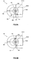
- flows in the compartment 20A at the upstream end in the autoclave 100 were analyzed by simulations regarding a model A in which the two slurry supply tubes 41 and 42 are arranged along the side wall as depicted in Figure 5A and a model B in which two slurry supply tubes 43 and 44 are arranged along a direction orthogonal to the side wall as depicted in Figure 5B .
- Figure 6A and Figure 6B depict results of simulations indicated by flow lines which visualize flows created only by rotational force of the stirring blades, with all slurry supply tubes eliminated.
- two vertically rotating axial flows F1 and F2 are formed, and a plane S formed by a downward flow is positioned slightly close to a hemisphere side by the rotation axis of the stirring blades 31A.
- Figure 6A and Figure 6B and Figure 7A and Figure 7B depict a state of flows in the compartment 20A at the upstream end viewed from the oblique above (A) and the state viewed from straight above (B). Also, a tendency of the flows of slurry is substantially determined by the positions where the slurry supply tubes are arranged.
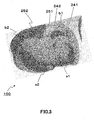
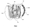
- FIG. 9 the results of a simulation indicated by flow lines which visualize flows in the compartment 20A for the model B depicted in Figure 5B described above are depicted in Figure 9 .
- a slurry supply tube 44 interposed on an opposite side of the side wall where the above-described slurry supply tubes 41 and 42 creates a flow of slurry heading for the partition wall 10A side. Slurry let flow from this slurry supply tube 44 becomes a flow that approaches and then directly collide with the partition wall 10A, thereby leading to a short path of slurry. Therefore, it is not preferable to arrange the slurry supply pipe 44 as in the model B.
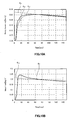
- Figure 10A depicts a residence time distribution from an entrance to an exit of slurry in the model A.
- a distribution curve AP1 indicates logical values of a residence time distribution of slurry predicted in a complete mixing model
- a distribution curve AB1 indicates a residence time distribution of slurry when the sulfuric acid supply tubes are short
- a distribution curve AG1 indicates a residence time distribution of slurry when the sulfuric acid supply tubes are long.
- Figure 10B depicts a residence time distribution from the entrance to the exit of slurry in the model B by using a distribution curve BB1.
- a distribution curve BP1 indicates logical values of a residence time distribution predicted in the complete mixing model.
- Figure 11A depicts a residence time distribution from an entrance to an exit of sulfuric acid in the model A.
- a distribution curve AP2 indicates logical values of a residence time distribution of sulfuric acid predicted in the complete mixing model
- a distribution curve AB2 indicates a residence time distribution of sulfuric acid when the sulfuric acid supply tubes are short
- a distribution curve AG2 indicates a residence time distribution of sulfuric acid when the sulfuric acid supply tubes are long.
- Figure 11B depicts a residence time distribution from the entrance to the exit of sulfuric acid in the model B by using a distribution curve BB2.
- a distribution curve BP2 indicates logical values of a residence time distribution predicted in the complete mixing model.
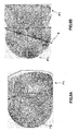
- Figure 12A depicts residence times of slurry near the partition wall 10A of the model A.
- Figure 12B depicts residence times of slurry near the partition wall 10A of the model B.
- red r indicates a residence time equal to or shorter than fifteen seconds
- blue b indicates a residence time equal to or longer than thirty seconds.
- Figure 12B has a red portion larger than that of Figure 12A , meaning that there is a relatively lot of slurry approaching a partition wall 10A portion fifteen seconds or shorter in the model B.
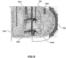
- Figure 13 depicts a vector diagram obtained as a result of a simulation of flows at a cross-section where the sulfuric acid supply tube 51 is installed.
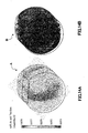
- Figure 14A depicts sulfuric acid concentrations near the partition wall 10A in the above-described model A.
- Figure 14B depicts sulfuric acid concentrations near the partition wall 10A in the above-described model B.
- FIG 17A depicts temperature contours of the buffles and the stirring blades 31A depending on the length of the sulfuric acid supply tubes 51 and 52 .
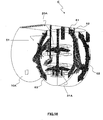
- Figure 17A depicts temperature contours of the buffles 61 to 63 and the stirring blades 31A with the number of revolutions of the stirring blades 31A being set at 42.4 rpm in the model C including the long sulfuric acid supply tubes 51L and 52L.
- Figure 17B depicts temperature contours of the buffles 61 to 63 and the stirring blades 31A with the number of revolutions of the stirring blades 31A being set at 42.4 rpm in the model D including the short sulfuric acid supply tubes 51S and 52S.
- starting material slurry and sulfuric acid are added to the above-described compartment 20A at the upstream end from the above-described starting material slurry discharge ports 41A and 42A and the sulfuric acid discharge ports 51A and 52A positioned at positions higher than the uppermost part of the above-described stirring blades 31A and lower than the contained liquid surface L via the two starting material slurry supply tubes 41 and 42 having the starting material slurry discharge ports 41A and 42A, respectively, and the two sulfuric acid supply tubes 51 and 52 having sulfuric acid discharge ports 51A and 52A, respectively, alternately disposed around a circumference of the stirring blades 31A of the stirring machine 31 provided in the compartment 20A at the upstream end as described above.
- starting material slurry and sulfuric acid are added from the above-described starting material slurry discharge ports 41A and 42A and sulfuric acid discharge ports 51A and 52A to the compartment 20A at the upstream end
- starting material slurry and sulfuric acid are alternately drawn toward the stirring blades 31A to increase the possibility of a contact. Therefore, mixing is proceeded more efficiently than ever to improve a leaching ratio. Also, a contact of high-concentration sulfuric acid with a wall surface can be prevented to decrease damage to the wall surface due to a contact of high-concentration sulfuric acid.
- a predetermined leaching ratio of 90% to 95% cannot be maintained unless the concentration of free sulfuric acid of the leachate is set at 50 g/L to 55 g/L.
- the predetermined leaching ratio can be maintained even if the concentration of free sulfuric acid of the leachate is set at 45 g/L to 50 g/L.
- the relation of the positions of the above-described starting material slurry discharge ports 41A and 42A and sulfuric acid discharge ports 51A and 52A with the autoclave 100 is not particularly limited, and any positions can be selected by rotation based on the center of the stirring blades 31A of the stirring machine 30A provided in the compartment 20A at the upstream end.
- the direction of the bottom side of the above-described regular triangle T is set parallel with the side wall of the autoclave 100.
- Operation was performed with a pressure in the autoclave of 5.5 MPaG, a temperature of 250 degrees Celsius, an Ni grade in crystal of 1.0% to 1.4%, and an amount of slurry influx to the autoclave of 300 m 3 to 700 m 3 per hour.
- ore slurry and sulfuric acid were supplied by applying the present invention.
- the leaching ratio of nickel was 92.5%. Also, operation was possible herein with the concentration of free sulfuric acid of the leachate being managed at 45 g/L to 50 g/L.
- Example 1 Without applying the present invention, operation was performed similarly to that of Example 1 except that present invention was not applied and ore slurry and sulfuric acid were supplied in conventional method in the conventional autoclave depicted in Figure 20 .
- the leaching ratio of nickel was 92.0%.
- the above-described leaching ratio was not able to be maintained unless the concentration of free sulfuric acid of the leachate was managed at 50 g/L to 55 g/L.
Landscapes
- Chemical & Material Sciences (AREA)
- Chemical Kinetics & Catalysis (AREA)
- Organic Chemistry (AREA)
- Engineering & Computer Science (AREA)
- Manufacturing & Machinery (AREA)
- Materials Engineering (AREA)
- Metallurgy (AREA)
- Mechanical Engineering (AREA)
- Environmental & Geological Engineering (AREA)
- Geochemistry & Mineralogy (AREA)
- General Life Sciences & Earth Sciences (AREA)
- Geology (AREA)
- Life Sciences & Earth Sciences (AREA)
- Inorganic Chemistry (AREA)
- Manufacture And Refinement Of Metals (AREA)
- Mixers Of The Rotary Stirring Type (AREA)
- Accessories For Mixers (AREA)
- Extraction Or Liquid Replacement (AREA)
Claims (4)
- Verfahren zum Zugeben von Ausgangsmaterialaufschlämmung und Schwefelsäure in einen Autoklav in einem Hochdrucksäureauslaugungsverfahren, worin erwärmte und druckbeaufschlagte Ausgangsmaterialaufschlämmung und die Schwefelsäure von einer Rührvorrichtung, bereitgestellt in jedem der Kompartimente in dem Autoklav, vielzählig unterteilt durch Unterteilungswände, zum Durchführen von Auslaugung der Ausgangsmaterialaufschlämmung gerührt werden und Aufschlämmung von einem Kompartiment an einer Anströmseite zu einem Kompartiment an einer Abströmseite zum sequenziellen Durchführen von Auslaugung transferiert wird, wobei
durch Ausgangsmaterialaufschlämmungszuführrohre, aufweisend die Ausgangsmaterialaufschlämmungsauslassanschlüsse und Schwefelsäurezuführrohre, aufweisend Schwefelsäureabführanschlüsse, alternierend angeordnet um einen Umfang von Rührblättern der Rührvorrichtung, bereitgestellt in einem Kompartiment an einem anströmseitigen Ende des Autoklavs, die Ausgangsmaterialaufschlämmung und die Schwefelsäure zu dem Kompartiment an dem anströmseitigen Ende aus den Ausgangsmaterialaufschlämmungauslassanschlüssen und den Schwefelsäureauslassanschlüssen, angeordnet an Positionen, höher als ein höchster Abschnitt der Rührblätter und niedriger als eine Oberfläche enthaltener Flüssigkeit, gegeben werden,
wobei
die Ausgangsmaterialaufschlämmung und die Schwefelsäure zu dem Kompartiment an dem anströmseitigen Ende aus den Ausgangsmaterialaufschlämmungauslassanschlüssen und den Schwefelsäureauslassanschlüssen gegeben werden, wobei die Ausgangsmaterialaufschlämmungsauslassanschlüsse und die Schwefelsäureauslassanschlüsse in planaren Positionen angeordnet sind, die Ausgangsmaterialaufschlämmungsauslassanschlüsse in einem Bereich eines Abstandes von 0,25D von, als Zentren, Scheitelpositionen an beiden Enden einer unteren Seite eines gleichschenkligen Dreiecks, angeordnet sind, wobei eine Höhe ein beliebiger Durchmesser D eines Kreises, gebildet durch Spitzen der Rührblätter, ist, das gleichschenklige Dreieck um einen Abstand von 0D bis 0,5D verschoben ist, so dass das gleichschenklige Dreieck einen Mittelpunkt der unteren Seite, angeordnet in einer Längsrichtung der unteren Seite des gleichschenkligen Dreiecks und an einer Abströmseite von einer Rotationsrichtung der Rührblätter, aufweist, und die Schwefelsäureauslassanschlüsse in einem Bereich eines Abstandes von 0,25 des Durchmessers von, als Zentren, der Mittelpunktposition der unteren Seite und der verbliebenen Scheitelpunktposition des gleichschenkligen Dreiecks angeordnet sind. - Verfahren zum Zugeben von Ausgangsmaterialaufschlämmung und Schwefelsäure in einen Autoklav nach Anspruch 1, wobei
die Längsrichtung der unteren Seite des gleichschenkligen Dreiecks parallel zu einer Seitenwand des Autoklavs ist. - Autoklav in einem Hochdrucksäureauslaugungsverfahren, worin erwärmte und druckbeaufschlagte Ausgangsmaterialaufschlämmung und Schwefelsäure von einer Rührvorrichtung, bereitgestellt in jedem der Kompartimente in dem Autoklav, vielzählig unterteilt durch Unterteilungswände, zum Durchführen von Auslaugung der Ausgangsmaterialaufschlämmung gerührt werden und Aufschlämmung von einem Kompartiment an einer Anströmseite zu einem Kompartiment an einer Abströmseite zum sequenziellen Durchführen von Auslaugung der Ausgangsmaterialaufschlämmung transferiert wird, wobei Ausgangsmaterialaufschlämmungszuführrohre, aufweisen die Ausgangsmaterialaufschlämmungsauslassanschlüsse und Schwefelsäurezuführrohre, aufweisend Schwefelsäureabführanschlüsse alternierend angeordnet sind um einen Umfang von Rührblättern der Rührvorrichtung,
bereitgestellt in einem Kompartiment an einem anströmseitigen Ende, und die Ausgangsmaterialaufschlämmunganschlüsse und die Schwefelsäureauslassanschlüsse an Positionen, höher als ein höchster Abschnitt der Rührblätter und niedriger als eine Oberfläche enthaltener Flüssigkeit, angeordnet sind, und durch die Ausgangsmaterialaufschlämmungszuführrohre und die Schwefelsäurezuführrohre die Ausgangsmaterialaufschlämmung und die Schwefelsäure zu dem Kompartiment an dem anströmseitigen Ende aus den Ausgangsmaterialaufschlämmungauslassanschlüssen und den Schwefelsäureauslassanschlüssen, alternierend angeordnet um einen Umfang der Rührblätter und an Positionen, höher als ein höchster Abschnitt der Rührblätter der Rührvorrichtung und niedriger als die Oberfläche enthaltener Flüssigkeit, gegeben werden, wobei
die Ausgangsmaterialaufschlämmungsauslassanschlüsse und die Schwefelsäureauslassanschlüsse in planaren Positionen angeordnet sind, die Ausgangsmaterialaufschlämmungsauslassanschlüsse in einem Bereich eines Abstandes von 0,25D von, als Zentren, Scheitelpositionen an beiden Enden einer unteren Seite eines gleichschenkligen Dreiecks, angeordnet sind, wobei eine Höhe ein beliebiger Durchmesser D eines Kreises, gebildet durch Spitzen der Rührblätter, ist, das gleichschenklige Dreieck um einen Abstand von 0D bis 0,5D verschoben ist, so dass das gleichschenklige Dreieck einen Mittelpunkt der unteren Seite, angeordnet in einer Längsrichtung der unteren Seite des gleichschenkligen Dreiecks und an einer Abströmseite von einer Rotationsrichtung der Rührblätter, aufweist, und die Schwefelsäureauslassanschlüsse in einem Bereich eines Abstandes von 0,25D von, als Zentren, der Mittelpunktposition der unteren Seite und der verbliebenen Scheitelpunktposition des gleichschenkligen Dreiecks angeordnet sind. - Autoklav nach Anspruch 3, wobei
die Längsrichtung der unteren Seite des gleichschenkligen Dreiecks parallel zu einer Seitenwand des Autoklavs ist.
Applications Claiming Priority (3)
| Application Number | Priority Date | Filing Date | Title |
|---|---|---|---|
| JP2012101614 | 2012-04-26 | ||
| JP2012260286A JP5387755B2 (ja) | 2012-04-26 | 2012-11-28 | 高圧酸浸出工程におけるオートクレーブへの原料スラリーと硫酸の添加方法及びオートクレーブ |
| PCT/JP2013/061158 WO2013161599A1 (ja) | 2012-04-26 | 2013-04-15 | 高圧酸浸出工程におけるオートクレーブへの原料スラリーと硫酸の添加方法及びオートクレーブ |
Publications (3)
| Publication Number | Publication Date |
|---|---|
| EP2843064A1 EP2843064A1 (de) | 2015-03-04 |
| EP2843064A4 EP2843064A4 (de) | 2015-12-30 |
| EP2843064B1 true EP2843064B1 (de) | 2018-09-05 |
Family
ID=49482923
Family Applications (1)
| Application Number | Title | Priority Date | Filing Date |
|---|---|---|---|
| EP13782392.8A Not-in-force EP2843064B1 (de) | 2012-04-26 | 2013-04-15 | Verfahren zum hinzufügen eines ausgangsmaterialschlamms und schwefelsäure zu einem autoklav in einem hochdruck-säureauslaugungsverfahren und autoklav |
Country Status (7)
| Country | Link |
|---|---|
| US (1) | US9970077B2 (de) |
| EP (1) | EP2843064B1 (de) |
| JP (1) | JP5387755B2 (de) |
| AU (1) | AU2013253807B2 (de) |
| CA (1) | CA2871604C (de) |
| PH (1) | PH12014502354B1 (de) |
| WO (1) | WO2013161599A1 (de) |
Families Citing this family (17)
| Publication number | Priority date | Publication date | Assignee | Title |
|---|---|---|---|---|
| JP5700029B2 (ja) * | 2012-12-11 | 2015-04-15 | 住友金属鉱山株式会社 | 硫化水素を含む貧液の処理方法及び処理装置 |
| CN104561536A (zh) * | 2014-12-25 | 2015-04-29 | 中国恩菲工程技术有限公司 | 浸出釜 |
| CN106621448A (zh) * | 2015-11-01 | 2017-05-10 | 江苏景泰石油化工装备有限公司 | 高效夹套式加热浸出罐 |
| JP6905211B2 (ja) * | 2017-07-24 | 2021-07-21 | 住友金属鉱山株式会社 | オートクレーブ |
| JP6589950B2 (ja) * | 2017-08-16 | 2019-10-16 | 住友金属鉱山株式会社 | 浸出処理方法、ニッケル酸化鉱石の湿式製錬方法 |
| KR101889681B1 (ko) | 2018-02-13 | 2018-08-17 | 고려아연 주식회사 | 오토클레이브 및 오토클레이브의 염 제거방법 |
| CN108706572B (zh) * | 2018-06-12 | 2021-05-28 | 合肥科塑信息科技有限公司 | 一种石墨烯基复合材料制取设备 |
| CN109022765B (zh) * | 2018-08-22 | 2020-07-14 | 贵州大学 | 一种搅拌浸出槽 |
| CN109078354A (zh) * | 2018-09-23 | 2018-12-25 | 天津市艾碘科技股份有限公司 | 一种工业粗碘回收搅拌装置 |
| JP7285427B2 (ja) * | 2019-07-16 | 2023-06-02 | 住友金属鉱山株式会社 | ニッケル酸化鉱石の浸出処理方法 |
| CN110605090B (zh) * | 2019-09-17 | 2021-07-30 | 义乌市倩飞科技有限公司 | 一种乙烯法聚氯乙烯乳液饱和梯度缩合的本体聚合系统 |
| CA3157698A1 (en) * | 2019-10-15 | 2021-04-22 | Metso Outotec Finland Oy | Autoclave and pressure oxidation method |
| JP2022104019A (ja) * | 2020-12-28 | 2022-07-08 | 住友金属鉱山株式会社 | 中和処理方法、ニッケル酸化鉱石の湿式製錬方法 |
| CN113999968B (zh) * | 2022-01-04 | 2022-06-07 | 中国恩菲工程技术有限公司 | 高压釜加酸系统及控制方法 |
| AU2023446744A1 (en) * | 2023-06-29 | 2025-02-06 | Gem Co., Ltd. | High-pressure reactor |
| DE102024114537A1 (de) * | 2024-05-23 | 2025-11-27 | EKATO Rühr- und Mischtechnik GmbH | Autoklavvorrichtung und Autoklav |
| WO2026083368A1 (en) * | 2024-10-14 | 2026-04-23 | Pt Esg New Energy Material | High-pressure reactor with adjustable baffles |
Citations (1)
| Publication number | Priority date | Publication date | Assignee | Title |
|---|---|---|---|---|
| WO2011147867A1 (fr) * | 2010-05-25 | 2011-12-01 | Forrest, George Arthur | Reacteur hydrometallurgique |
Family Cites Families (19)
| Publication number | Priority date | Publication date | Assignee | Title |
|---|---|---|---|---|
| GB808609A (en) * | 1956-05-15 | 1959-02-04 | Hercules Powder Co Ltd | Improvements in or relating to process and apparatus for the continuous manufacture of nitrocellulose |
| DE1091568B (de) | 1957-08-02 | 1960-10-27 | Bergwerksgesellschaft Hibernia | Verfahren und Vorrichtung zur kontinuierlichen Durchfuehrung von Reaktionen zwischen Gasen und Fluessigkeiten |
| US3121759A (en) * | 1960-08-23 | 1964-02-18 | Kellogg M W Co | Cascade liquid-vapor reactor |
| US3961908A (en) * | 1974-02-27 | 1976-06-08 | Freeport Minerals Company | Autoclave system for leaching sulfide concentrates |
| CA1228483A (en) * | 1984-09-19 | 1987-10-27 | Donald R. Weir | Process for the pressure oxidation acid leaching of non-ferrous metal and iron-containing sulphidic material |
| JPH0791599B2 (ja) * | 1989-01-25 | 1995-10-04 | 住友金属鉱山株式会社 | 有価金属の分離方法 |
| US5071477A (en) * | 1990-05-03 | 1991-12-10 | American Barrick Resources Corporation of Toronto | Process for recovery of gold from refractory ores |
| JPH0784623A (ja) | 1993-09-14 | 1995-03-31 | Zexel Corp | Cad/cam結合システム |
| US5535992A (en) | 1995-03-07 | 1996-07-16 | Goro Nickel S.A. | Apparatus and method for acidic leaching of lateritic ores |
| US5856533A (en) * | 1995-12-28 | 1999-01-05 | Praxair Technology, Inc. | High efficiency heat and mass transfer for vapor phase heterogeneous reactions |
| US6299776B1 (en) * | 1997-12-23 | 2001-10-09 | General Signal Corporation | Biochemical oxidation system and process |
| US6368381B1 (en) * | 1998-03-11 | 2002-04-09 | Placer Dome Technical Services, Ltd. | Autoclave using agitator and sparge tube to provide high oxygen transfer rate to metal-containing solutions |
| US6835230B2 (en) * | 2001-03-28 | 2004-12-28 | Dowa Mining Co., Ltd. | Method for leaching zinc concentrate |
| CA2557872C (en) * | 2004-01-07 | 2012-10-23 | Hydromet (Pty) Ltd. | Exothermic pressure leach autoclave circuits |
| JP4525428B2 (ja) | 2004-05-13 | 2010-08-18 | 住友金属鉱山株式会社 | ニッケル酸化鉱石の湿式製錬方法 |
| US7604783B2 (en) * | 2004-12-22 | 2009-10-20 | Placer Dome Technical Services Limited | Reduction of lime consumption when treating refractor gold ores or concentrates |
| BRPI0505544B1 (pt) | 2005-11-10 | 2014-02-04 | Processo de lixiviação combinada | |
| US8061888B2 (en) * | 2006-03-17 | 2011-11-22 | Barrick Gold Corporation | Autoclave with underflow dividers |
| JP5359989B2 (ja) | 2010-05-18 | 2013-12-04 | 住友金属鉱山株式会社 | 生成硫化物の付着防止方法 |
-
2012
- 2012-11-28 JP JP2012260286A patent/JP5387755B2/ja active Active
-
2013
- 2013-04-15 EP EP13782392.8A patent/EP2843064B1/de not_active Not-in-force
- 2013-04-15 CA CA2871604A patent/CA2871604C/en not_active Expired - Fee Related
- 2013-04-15 WO PCT/JP2013/061158 patent/WO2013161599A1/ja not_active Ceased
- 2013-04-15 AU AU2013253807A patent/AU2013253807B2/en active Active
- 2013-04-15 US US14/396,300 patent/US9970077B2/en active Active
-
2014
- 2014-10-21 PH PH12014502354A patent/PH12014502354B1/en unknown
Patent Citations (1)
| Publication number | Priority date | Publication date | Assignee | Title |
|---|---|---|---|---|
| WO2011147867A1 (fr) * | 2010-05-25 | 2011-12-01 | Forrest, George Arthur | Reacteur hydrometallurgique |
Also Published As
| Publication number | Publication date |
|---|---|
| JP5387755B2 (ja) | 2014-01-15 |
| CA2871604A1 (en) | 2013-10-31 |
| US20150086450A1 (en) | 2015-03-26 |
| AU2013253807A1 (en) | 2014-11-13 |
| US9970077B2 (en) | 2018-05-15 |
| EP2843064A1 (de) | 2015-03-04 |
| JP2013241668A (ja) | 2013-12-05 |
| AU2013253807B2 (en) | 2017-03-02 |
| WO2013161599A1 (ja) | 2013-10-31 |
| CA2871604C (en) | 2019-04-09 |
| PH12014502354A1 (en) | 2015-01-12 |
| EP2843064A4 (de) | 2015-12-30 |
| PH12014502354B1 (en) | 2019-04-26 |
Similar Documents
| Publication | Publication Date | Title |
|---|---|---|
| CA2871604C (en) | Method for adding starting material slurry and sulfuric acid to autoclave in high pressure acid leaching process and autoclave | |
| JP5418660B2 (ja) | 高圧酸浸出工程におけるオートクレーブ装置 | |
| Baba et al. | Characterization and kinetic study on ammonia leaching of complex copper ore | |
| JP6135609B2 (ja) | オートクレーブへのガス吹込み方法 | |
| JP5500304B2 (ja) | 高圧酸浸出工程におけるオートクレーブ装置 | |
| AU2012365089A2 (en) | Flash vessel and method for operating same | |
| He et al. | Enhanced extraction of nickel from limonitic laterite via improved nitric acid pressure leaching process | |
| CN103146934B (zh) | 一种利用微流体技术萃取分离钴、镍的方法 | |
| Zheng et al. | Continuous hydrothermal leaching of LiCoO 2 cathode materials by using citric acid | |
| Marsden et al. | Medium-temperature pressure leaching of copper concentrates—Part I: Chemistry and initial process development | |
| Chang et al. | Efficient reductive leaching of valuable elements from oxygen pressure leaching residue of high-grade nickel matte within sulfur dioxide | |
| EP4516390B1 (de) | Hochdruckreaktor | |
| Li et al. | Efficient and selective leaching of nickel and cobalt from nickel laterite ore by a combined atmospheric acid leaching-ferric chloride solution leaching process: optimization and mechanism | |
| JP5482955B2 (ja) | 高圧酸浸出工程におけるオートクレーブへの原料スラリーと硫酸の添加方法及びオートクレーブ | |
| AU2015377611B2 (en) | Countercurrent type direct-heating heat exchanger | |
| Feng et al. | Microfluidic strategy for rapid and efficient extraction of scandium ions from red mud | |
| US20150050188A1 (en) | Multi-compartment reactor and method for controlling retention time in a multi-compartment reactor | |
| EP3533888A1 (de) | Hydrometallurgisches verfahren für nickeloxiderz | |
| Hu et al. | Oxidative acid leaching behavior of Fe–Ni–Co alloy powder derived from a laterite ore | |
| Marsden et al. | Medium-temperature pressure leaching of copper concentrates—Part II: Development of direct electrowinning and an acid-autogenous process | |
| Dickson et al. | Multilevel Factorial Optimisation of Acid-to-Ore Ratio and Solids Concentration in Hydrometallurgical Recovery of Nickel from Laterite Ore | |
| Liu et al. | New design and sustainability assessment of industrial plant for continuous supercritical hydrothermal synthesis of zirconia | |
| JP7396072B2 (ja) | 混合装置及び混合方法 | |
| WO2017159837A1 (ja) | 向流式直接加熱型熱交換器 | |
| JP2018071918A (ja) | 向流式直接加熱型熱交換器 |
Legal Events
| Date | Code | Title | Description |
|---|---|---|---|
| PUAI | Public reference made under article 153(3) epc to a published international application that has entered the european phase |
Free format text: ORIGINAL CODE: 0009012 |
|
| 17P | Request for examination filed |
Effective date: 20141030 |
|
| AK | Designated contracting states |
Kind code of ref document: A1 Designated state(s): AL AT BE BG CH CY CZ DE DK EE ES FI FR GB GR HR HU IE IS IT LI LT LU LV MC MK MT NL NO PL PT RO RS SE SI SK SM TR |
|
| AX | Request for extension of the european patent |
Extension state: BA ME |
|
| DAX | Request for extension of the european patent (deleted) | ||
| RA4 | Supplementary search report drawn up and despatched (corrected) |
Effective date: 20151201 |
|
| RIC1 | Information provided on ipc code assigned before grant |
Ipc: B01F 15/00 20060101ALI20151125BHEP Ipc: C22B 3/00 20060101ALI20151125BHEP Ipc: C22B 3/10 20060101ALI20151125BHEP Ipc: B01F 7/00 20060101ALI20151125BHEP Ipc: B01F 7/16 20060101ALI20151125BHEP Ipc: B01J 19/00 20060101ALI20151125BHEP Ipc: C22B 23/00 20060101AFI20151125BHEP Ipc: C22B 3/02 20060101ALI20151125BHEP Ipc: B01F 13/10 20060101ALI20151125BHEP Ipc: C22B 3/04 20060101ALI20151125BHEP Ipc: B01D 11/02 20060101ALI20151125BHEP Ipc: B01F 7/22 20060101ALI20151125BHEP Ipc: B01J 3/04 20060101ALI20151125BHEP Ipc: B01F 15/02 20060101ALI20151125BHEP Ipc: B01J 19/18 20060101ALI20151125BHEP Ipc: B01J 3/02 20060101ALI20151125BHEP |
|
| STAA | Information on the status of an ep patent application or granted ep patent |
Free format text: STATUS: EXAMINATION IS IN PROGRESS |
|
| 17Q | First examination report despatched |
Effective date: 20171222 |
|
| REG | Reference to a national code |
Ref country code: DE Ref legal event code: R079 Ref document number: 602013043213 Country of ref document: DE Free format text: PREVIOUS MAIN CLASS: C22B0023000000 Ipc: B01D0011020000 |
|
| GRAP | Despatch of communication of intention to grant a patent |
Free format text: ORIGINAL CODE: EPIDOSNIGR1 |
|
| RIC1 | Information provided on ipc code assigned before grant |
Ipc: B01F 15/00 20060101ALI20180329BHEP Ipc: B01F 7/22 20060101ALI20180329BHEP Ipc: B01J 19/18 20060101ALI20180329BHEP Ipc: C22B 3/10 20060101ALI20180329BHEP Ipc: B01F 13/10 20060101ALI20180329BHEP Ipc: B01F 7/00 20060101ALI20180329BHEP Ipc: B01F 15/02 20060101ALI20180329BHEP Ipc: B01F 7/16 20060101ALI20180329BHEP Ipc: C22B 23/00 20060101ALI20180329BHEP Ipc: C22B 3/02 20060101ALI20180329BHEP Ipc: B01J 19/00 20060101ALI20180329BHEP Ipc: B01J 3/04 20060101ALI20180329BHEP Ipc: B01D 11/02 20060101AFI20180329BHEP |
|
| STAA | Information on the status of an ep patent application or granted ep patent |
Free format text: STATUS: GRANT OF PATENT IS INTENDED |
|
| INTG | Intention to grant announced |
Effective date: 20180503 |
|
| GRAS | Grant fee paid |
Free format text: ORIGINAL CODE: EPIDOSNIGR3 |
|
| GRAA | (expected) grant |
Free format text: ORIGINAL CODE: 0009210 |
|
| STAA | Information on the status of an ep patent application or granted ep patent |
Free format text: STATUS: THE PATENT HAS BEEN GRANTED |
|
| RIN1 | Information on inventor provided before grant (corrected) |
Inventor name: NAKAI, OSAMU Inventor name: SAKAMOTO, TAKASHI Inventor name: KITAHARA, MASAKI Inventor name: MATSUBARA, SATOSHI Inventor name: ISHIKAWA, HARUO Inventor name: MAKI, KOICHIRO Inventor name: KYODA, YOJI |
|
| AK | Designated contracting states |
Kind code of ref document: B1 Designated state(s): AL AT BE BG CH CY CZ DE DK EE ES FI FR GB GR HR HU IE IS IT LI LT LU LV MC MK MT NL NO PL PT RO RS SE SI SK SM TR |
|
| REG | Reference to a national code |
Ref country code: GB Ref legal event code: FG4D |
|
| REG | Reference to a national code |
Ref country code: CH Ref legal event code: EP |
|
| REG | Reference to a national code |
Ref country code: AT Ref legal event code: REF Ref document number: 1037178 Country of ref document: AT Kind code of ref document: T Effective date: 20180915 |
|
| REG | Reference to a national code |
Ref country code: IE Ref legal event code: FG4D |
|
| REG | Reference to a national code |
Ref country code: DE Ref legal event code: R096 Ref document number: 602013043213 Country of ref document: DE |
|
| REG | Reference to a national code |
Ref country code: NL Ref legal event code: MP Effective date: 20180905 |
|
| REG | Reference to a national code |
Ref country code: LT Ref legal event code: MG4D |
|
| PG25 | Lapsed in a contracting state [announced via postgrant information from national office to epo] |
Ref country code: FI Free format text: LAPSE BECAUSE OF FAILURE TO SUBMIT A TRANSLATION OF THE DESCRIPTION OR TO PAY THE FEE WITHIN THE PRESCRIBED TIME-LIMIT Effective date: 20180905 Ref country code: BG Free format text: LAPSE BECAUSE OF FAILURE TO SUBMIT A TRANSLATION OF THE DESCRIPTION OR TO PAY THE FEE WITHIN THE PRESCRIBED TIME-LIMIT Effective date: 20181205 Ref country code: LT Free format text: LAPSE BECAUSE OF FAILURE TO SUBMIT A TRANSLATION OF THE DESCRIPTION OR TO PAY THE FEE WITHIN THE PRESCRIBED TIME-LIMIT Effective date: 20180905 Ref country code: GR Free format text: LAPSE BECAUSE OF FAILURE TO SUBMIT A TRANSLATION OF THE DESCRIPTION OR TO PAY THE FEE WITHIN THE PRESCRIBED TIME-LIMIT Effective date: 20181206 Ref country code: NO Free format text: LAPSE BECAUSE OF FAILURE TO SUBMIT A TRANSLATION OF THE DESCRIPTION OR TO PAY THE FEE WITHIN THE PRESCRIBED TIME-LIMIT Effective date: 20181205 Ref country code: RS Free format text: LAPSE BECAUSE OF FAILURE TO SUBMIT A TRANSLATION OF THE DESCRIPTION OR TO PAY THE FEE WITHIN THE PRESCRIBED TIME-LIMIT Effective date: 20180905 Ref country code: SE Free format text: LAPSE BECAUSE OF FAILURE TO SUBMIT A TRANSLATION OF THE DESCRIPTION OR TO PAY THE FEE WITHIN THE PRESCRIBED TIME-LIMIT Effective date: 20180905 |
|
| REG | Reference to a national code |
Ref country code: AT Ref legal event code: MK05 Ref document number: 1037178 Country of ref document: AT Kind code of ref document: T Effective date: 20180905 |
|
| PG25 | Lapsed in a contracting state [announced via postgrant information from national office to epo] |
Ref country code: AL Free format text: LAPSE BECAUSE OF FAILURE TO SUBMIT A TRANSLATION OF THE DESCRIPTION OR TO PAY THE FEE WITHIN THE PRESCRIBED TIME-LIMIT Effective date: 20180905 Ref country code: LV Free format text: LAPSE BECAUSE OF FAILURE TO SUBMIT A TRANSLATION OF THE DESCRIPTION OR TO PAY THE FEE WITHIN THE PRESCRIBED TIME-LIMIT Effective date: 20180905 Ref country code: HR Free format text: LAPSE BECAUSE OF FAILURE TO SUBMIT A TRANSLATION OF THE DESCRIPTION OR TO PAY THE FEE WITHIN THE PRESCRIBED TIME-LIMIT Effective date: 20180905 |
|
| PG25 | Lapsed in a contracting state [announced via postgrant information from national office to epo] |
Ref country code: IT Free format text: LAPSE BECAUSE OF FAILURE TO SUBMIT A TRANSLATION OF THE DESCRIPTION OR TO PAY THE FEE WITHIN THE PRESCRIBED TIME-LIMIT Effective date: 20180905 Ref country code: EE Free format text: LAPSE BECAUSE OF FAILURE TO SUBMIT A TRANSLATION OF THE DESCRIPTION OR TO PAY THE FEE WITHIN THE PRESCRIBED TIME-LIMIT Effective date: 20180905 Ref country code: PL Free format text: LAPSE BECAUSE OF FAILURE TO SUBMIT A TRANSLATION OF THE DESCRIPTION OR TO PAY THE FEE WITHIN THE PRESCRIBED TIME-LIMIT Effective date: 20180905 Ref country code: AT Free format text: LAPSE BECAUSE OF FAILURE TO SUBMIT A TRANSLATION OF THE DESCRIPTION OR TO PAY THE FEE WITHIN THE PRESCRIBED TIME-LIMIT Effective date: 20180905 Ref country code: IS Free format text: LAPSE BECAUSE OF FAILURE TO SUBMIT A TRANSLATION OF THE DESCRIPTION OR TO PAY THE FEE WITHIN THE PRESCRIBED TIME-LIMIT Effective date: 20190105 Ref country code: NL Free format text: LAPSE BECAUSE OF FAILURE TO SUBMIT A TRANSLATION OF THE DESCRIPTION OR TO PAY THE FEE WITHIN THE PRESCRIBED TIME-LIMIT Effective date: 20180905 Ref country code: RO Free format text: LAPSE BECAUSE OF FAILURE TO SUBMIT A TRANSLATION OF THE DESCRIPTION OR TO PAY THE FEE WITHIN THE PRESCRIBED TIME-LIMIT Effective date: 20180905 Ref country code: CZ Free format text: LAPSE BECAUSE OF FAILURE TO SUBMIT A TRANSLATION OF THE DESCRIPTION OR TO PAY THE FEE WITHIN THE PRESCRIBED TIME-LIMIT Effective date: 20180905 Ref country code: ES Free format text: LAPSE BECAUSE OF FAILURE TO SUBMIT A TRANSLATION OF THE DESCRIPTION OR TO PAY THE FEE WITHIN THE PRESCRIBED TIME-LIMIT Effective date: 20180905 |
|
| PG25 | Lapsed in a contracting state [announced via postgrant information from national office to epo] |
Ref country code: SK Free format text: LAPSE BECAUSE OF FAILURE TO SUBMIT A TRANSLATION OF THE DESCRIPTION OR TO PAY THE FEE WITHIN THE PRESCRIBED TIME-LIMIT Effective date: 20180905 Ref country code: PT Free format text: LAPSE BECAUSE OF FAILURE TO SUBMIT A TRANSLATION OF THE DESCRIPTION OR TO PAY THE FEE WITHIN THE PRESCRIBED TIME-LIMIT Effective date: 20190105 Ref country code: SM Free format text: LAPSE BECAUSE OF FAILURE TO SUBMIT A TRANSLATION OF THE DESCRIPTION OR TO PAY THE FEE WITHIN THE PRESCRIBED TIME-LIMIT Effective date: 20180905 |
|
| REG | Reference to a national code |
Ref country code: DE Ref legal event code: R097 Ref document number: 602013043213 Country of ref document: DE |
|
| PLBE | No opposition filed within time limit |
Free format text: ORIGINAL CODE: 0009261 |
|
| STAA | Information on the status of an ep patent application or granted ep patent |
Free format text: STATUS: NO OPPOSITION FILED WITHIN TIME LIMIT |
|
| PG25 | Lapsed in a contracting state [announced via postgrant information from national office to epo] |
Ref country code: DK Free format text: LAPSE BECAUSE OF FAILURE TO SUBMIT A TRANSLATION OF THE DESCRIPTION OR TO PAY THE FEE WITHIN THE PRESCRIBED TIME-LIMIT Effective date: 20180905 |
|
| 26N | No opposition filed |
Effective date: 20190606 |
|
| PG25 | Lapsed in a contracting state [announced via postgrant information from national office to epo] |
Ref country code: SI Free format text: LAPSE BECAUSE OF FAILURE TO SUBMIT A TRANSLATION OF THE DESCRIPTION OR TO PAY THE FEE WITHIN THE PRESCRIBED TIME-LIMIT Effective date: 20180905 |
|
| REG | Reference to a national code |
Ref country code: DE Ref legal event code: R119 Ref document number: 602013043213 Country of ref document: DE |
|
| REG | Reference to a national code |
Ref country code: CH Ref legal event code: PL |
|
| REG | Reference to a national code |
Ref country code: BE Ref legal event code: MM Effective date: 20190430 |
|
| PG25 | Lapsed in a contracting state [announced via postgrant information from national office to epo] |
Ref country code: MC Free format text: LAPSE BECAUSE OF FAILURE TO SUBMIT A TRANSLATION OF THE DESCRIPTION OR TO PAY THE FEE WITHIN THE PRESCRIBED TIME-LIMIT Effective date: 20180905 Ref country code: LU Free format text: LAPSE BECAUSE OF NON-PAYMENT OF DUE FEES Effective date: 20190415 |
|
| PG25 | Lapsed in a contracting state [announced via postgrant information from national office to epo] |
Ref country code: LI Free format text: LAPSE BECAUSE OF NON-PAYMENT OF DUE FEES Effective date: 20190430 Ref country code: CH Free format text: LAPSE BECAUSE OF NON-PAYMENT OF DUE FEES Effective date: 20190430 Ref country code: DE Free format text: LAPSE BECAUSE OF NON-PAYMENT OF DUE FEES Effective date: 20191101 |
|
| PG25 | Lapsed in a contracting state [announced via postgrant information from national office to epo] |
Ref country code: BE Free format text: LAPSE BECAUSE OF NON-PAYMENT OF DUE FEES Effective date: 20190430 |
|
| PG25 | Lapsed in a contracting state [announced via postgrant information from national office to epo] |
Ref country code: TR Free format text: LAPSE BECAUSE OF FAILURE TO SUBMIT A TRANSLATION OF THE DESCRIPTION OR TO PAY THE FEE WITHIN THE PRESCRIBED TIME-LIMIT Effective date: 20180905 |
|
| PG25 | Lapsed in a contracting state [announced via postgrant information from national office to epo] |
Ref country code: IE Free format text: LAPSE BECAUSE OF NON-PAYMENT OF DUE FEES Effective date: 20190415 |
|
| PGFP | Annual fee paid to national office [announced via postgrant information from national office to epo] |
Ref country code: FR Payment date: 20200312 Year of fee payment: 8 |
|
| PGFP | Annual fee paid to national office [announced via postgrant information from national office to epo] |
Ref country code: GB Payment date: 20200408 Year of fee payment: 8 |
|
| PG25 | Lapsed in a contracting state [announced via postgrant information from national office to epo] |
Ref country code: CY Free format text: LAPSE BECAUSE OF FAILURE TO SUBMIT A TRANSLATION OF THE DESCRIPTION OR TO PAY THE FEE WITHIN THE PRESCRIBED TIME-LIMIT Effective date: 20180905 |
|
| PG25 | Lapsed in a contracting state [announced via postgrant information from national office to epo] |
Ref country code: MT Free format text: LAPSE BECAUSE OF FAILURE TO SUBMIT A TRANSLATION OF THE DESCRIPTION OR TO PAY THE FEE WITHIN THE PRESCRIBED TIME-LIMIT Effective date: 20180905 Ref country code: HU Free format text: LAPSE BECAUSE OF FAILURE TO SUBMIT A TRANSLATION OF THE DESCRIPTION OR TO PAY THE FEE WITHIN THE PRESCRIBED TIME-LIMIT; INVALID AB INITIO Effective date: 20130415 |
|
| GBPC | Gb: european patent ceased through non-payment of renewal fee |
Effective date: 20210415 |
|
| PG25 | Lapsed in a contracting state [announced via postgrant information from national office to epo] |
Ref country code: GB Free format text: LAPSE BECAUSE OF NON-PAYMENT OF DUE FEES Effective date: 20210415 Ref country code: FR Free format text: LAPSE BECAUSE OF NON-PAYMENT OF DUE FEES Effective date: 20210430 |
|
| PG25 | Lapsed in a contracting state [announced via postgrant information from national office to epo] |
Ref country code: MK Free format text: LAPSE BECAUSE OF FAILURE TO SUBMIT A TRANSLATION OF THE DESCRIPTION OR TO PAY THE FEE WITHIN THE PRESCRIBED TIME-LIMIT Effective date: 20180905 |