EP2840445B1 - Fotografierverfahren und elektronische vorrichtung - Google Patents
Fotografierverfahren und elektronische vorrichtung Download PDFInfo
- Publication number
- EP2840445B1 EP2840445B1 EP12874817.5A EP12874817A EP2840445B1 EP 2840445 B1 EP2840445 B1 EP 2840445B1 EP 12874817 A EP12874817 A EP 12874817A EP 2840445 B1 EP2840445 B1 EP 2840445B1
- Authority
- EP
- European Patent Office
- Prior art keywords
- shooting
- photographs
- photograph
- visual angle
- panoramic
- Prior art date
- Legal status (The legal status is an assumption and is not a legal conclusion. Google has not performed a legal analysis and makes no representation as to the accuracy of the status listed.)
- Active
Links
Images

Classifications
-
- G—PHYSICS
- G03—PHOTOGRAPHY; CINEMATOGRAPHY; ANALOGOUS TECHNIQUES USING WAVES OTHER THAN OPTICAL WAVES; ELECTROGRAPHY; HOLOGRAPHY
- G03B—APPARATUS OR ARRANGEMENTS FOR TAKING PHOTOGRAPHS OR FOR PROJECTING OR VIEWING THEM; APPARATUS OR ARRANGEMENTS EMPLOYING ANALOGOUS TECHNIQUES USING WAVES OTHER THAN OPTICAL WAVES; ACCESSORIES THEREFOR
- G03B35/00—Stereoscopic photography
- G03B35/02—Stereoscopic photography by sequential recording
- G03B35/04—Stereoscopic photography by sequential recording with movement of beam-selecting members in a system defining two or more viewpoints
-
- G—PHYSICS
- G03—PHOTOGRAPHY; CINEMATOGRAPHY; ANALOGOUS TECHNIQUES USING WAVES OTHER THAN OPTICAL WAVES; ELECTROGRAPHY; HOLOGRAPHY
- G03B—APPARATUS OR ARRANGEMENTS FOR TAKING PHOTOGRAPHS OR FOR PROJECTING OR VIEWING THEM; APPARATUS OR ARRANGEMENTS EMPLOYING ANALOGOUS TECHNIQUES USING WAVES OTHER THAN OPTICAL WAVES; ACCESSORIES THEREFOR
- G03B37/00—Panoramic or wide-screen photography; Photographing extended surfaces, e.g. for surveying; Photographing internal surfaces, e.g. of pipe
- G03B37/02—Panoramic or wide-screen photography; Photographing extended surfaces, e.g. for surveying; Photographing internal surfaces, e.g. of pipe with scanning movement of lens or cameras
-
- G—PHYSICS
- G03—PHOTOGRAPHY; CINEMATOGRAPHY; ANALOGOUS TECHNIQUES USING WAVES OTHER THAN OPTICAL WAVES; ELECTROGRAPHY; HOLOGRAPHY
- G03B—APPARATUS OR ARRANGEMENTS FOR TAKING PHOTOGRAPHS OR FOR PROJECTING OR VIEWING THEM; APPARATUS OR ARRANGEMENTS EMPLOYING ANALOGOUS TECHNIQUES USING WAVES OTHER THAN OPTICAL WAVES; ACCESSORIES THEREFOR
- G03B5/00—Adjustment of optical system relative to image or object surface other than for focusing
-
- H—ELECTRICITY
- H04—ELECTRIC COMMUNICATION TECHNIQUE
- H04N—PICTORIAL COMMUNICATION, e.g. TELEVISION
- H04N13/00—Stereoscopic video systems; Multi-view video systems; Details thereof
- H04N13/20—Image signal generators
- H04N13/204—Image signal generators using stereoscopic image cameras
- H04N13/207—Image signal generators using stereoscopic image cameras using a single two-dimensional [2D] image sensor
-
- H—ELECTRICITY
- H04—ELECTRIC COMMUNICATION TECHNIQUE
- H04N—PICTORIAL COMMUNICATION, e.g. TELEVISION
- H04N23/00—Cameras or camera modules comprising electronic image sensors; Control thereof
- H04N23/60—Control of cameras or camera modules
- H04N23/698—Control of cameras or camera modules for achieving an enlarged field of view, e.g. panoramic image capture
-
- H—ELECTRICITY
- H04—ELECTRIC COMMUNICATION TECHNIQUE
- H04N—PICTORIAL COMMUNICATION, e.g. TELEVISION
- H04N23/00—Cameras or camera modules comprising electronic image sensors; Control thereof
- H04N23/70—Circuitry for compensating brightness variation in the scene
- H04N23/75—Circuitry for compensating brightness variation in the scene by influencing optical camera components
-
- H—ELECTRICITY
- H04—ELECTRIC COMMUNICATION TECHNIQUE
- H04N—PICTORIAL COMMUNICATION, e.g. TELEVISION
- H04N13/00—Stereoscopic video systems; Multi-view video systems; Details thereof
- H04N13/10—Processing, recording or transmission of stereoscopic or multi-view image signals
- H04N13/106—Processing image signals
Definitions
- the present invention relates to the communication field, and in particular, to a photograph shooting method and electronic device.
- its focal distance may be fixed; in this case, its shooting visual angle is fixed as well.
- the size of its visual angle can be relatively changed through the digital zoom; when the visual angle becomes larger, the imaging area becomes larger, but each object in the presented image becomes smaller; when the visual angle becomes smaller, the imaging area becomes smaller, and the object in the presented image will become larger correspondingly.
- even the shooting visual angle can be changed through the zoom, the change of its shooting visual angle is limited.
- the mobile phone lens or the shooting system has the following insufficiency:
- the pixel of the mobile phone has already been very high, even some has reached the level of the digital camera. And some mobile phones has already supported the 3D display effect of naked eye. But the effect is still not very good when the mobile phone shoots the panoramic photograph or the 3D photograph, even a lot of mobile phones do not support the 3D shooting.
- JP 2007334558 A provides an image processor, method and program.
- a brightness magnification approximate function calculating part 106 calculates an approximate function that approximates the change of the exposure magnification to the angle of the photographic directions of the respective images from the photographic conditions of the plurality of images
- a luminance adjustment part 107 adjusts the luminance of the plurality of images in a manner of changing the luminance continuously in the direction of joining the images according to the approximate function
- an image composition part 108 composites the plurality of images, the luminance of which have been adjusted, into a single composite image by joining them together.
- the present invention can be applied to digital still cameras.
- JP 2009049854 A provides a compound-eye photographing apparatus.
- the compound-eye photographing apparatus 1 has a structure storing a first camera 10 and a second camera 20 in a housing 2.
- the second camera 20 is provided with a unit case 21 rotatably attached to the housing 2, an image forming optical system 22 integrally attached to the unit case 21, a light bending member 23 arranged in the unit case 21 to bend an object image formed by the image forming optical system 22 to a direction LL parallel with a rotational axis CL of the unit case 21, and an image forming element 24 fixed in the unit case 21 to pick up the object image bent by the light bending member 22.
- JP2000295504 A provides a digital camera where a turning performance of a rotary mechanism of a camera unit is enhanced so as to improve functions of the digital camera.
- a camera unit 2 is provided with a CCD sensor 12 and an optical lens 7. This camera unit 2 is placed to an upper side of a main body 1 provided with a lid crystal display device 6, and fitted to the main body 1 in a way that the camera unit 2 is opened/closed vertically around a rotary shaft 16. Furthermore, the main body 1 is provided with a rotary mechanism 3 that is turned in a circumferential direction with respect to the axis center of a holder section 4. Thus, longitudinal photographing and panorama photographing can be attained without the need for moving the main body.
- US2007189747 A1 provides a camera system including a camera apparatus for shooting an object to output an image signal and a camera control apparatus for controlling the camera apparatus such that the camera apparatus shoots a plurality of images constructing a panorama image in a predetermined order while changing zoom magnifications based on previously-determined setting and making a panorama image by joining a plurality of images with different zoom magnifications shot by the camera apparatus together.
- CN1979335 A provides a camera system including a camera device for shooting images to output image signals, and a camera controlling device for controlling the camera device, thereby the camera device shoots a plurality of images which constructs a panorama image in a predetermined order while changing a zooming-in multiple based on a predetermined set, and combines the plurality of images which are shot by the camera device and have different zooming-in multiples to form the panorama image.
- the embodiment of the present invention will provide a photograph shooting method and electronic device, used for better shooting the panoramic photograph.
- the step of processing the at least two photographs comprises: jointing the at least two photographs, to obtain one panoramic photograph.
- the step of jointing the at least two photographs comprises: when the at least two photographs have overlap portions, and when jointing the at least two photographs, selecting the overlap portion of any photograph in the at least two photographs, or superposing the overlap portions of two photographs.
- the image processing module may be configured to: process the at least two photographs to obtain one panoramic photograph by the following way: jointing the at least two photographs, to obtain one panoramic photograph.
- the image processing module may be further configured to: when the at least two photographs have overlap portions, and when jointing the at least two photographs, select the overlap portion of any photograph in the at least two photographs, or superpose the overlap portions of the two photographs.
- the photograph shooting method in the embodiment of the present invention includes determining a shooting focal distance and a shooting visual angle; automatically shooting at least two photographs, comprising all objects required to be shot in an area of the shooting visual angle, according to the shooting focal distance and the shooting visual angle which are determined; and processing the at least two photographs to obtain one panoramic photograph.
- the electronic device can perform shooting automatically, and it can shoot at least two photographs automatically, and then process the shot photographs to obtain one panoramic photograph, thus providing a panoramic photograph shooting method, in order to shoot all objects in the selected area clearly and further obtain the panoramic photograph with a better effect.
- the photograph shooting method in the embodiment of the present invention is introduced through the realizing procedures hereinafter.
- a major method flow of photograph shooting in the embodiment of the present invention is as follows, and the method can be applied in an electronic device with a lens assembly and an imaging system.
- step 101 a shooting focal distance and a shooting visual angle are determined.
- the electronic device can have many kinds of shooting modes, for example, it can have a normal mode, a panoramic mode, a 3D mode, a video recording mode, etc., the user can shoot normally in the normal mode, shoot the panoramic photograph in the panoramic mode, shoot the 3D photo in the 3D mode and record a video in the video recording mode.
- the shooting mode can be determined at first. What the present embodiment introduces is the panoramic photograph shooting method, therefore, the shooting mode can be determined as the panoramic mode at first.
- the first panoramic submode can be an up-and-down panoramic mode, that is, the panoramic photograph can be shot in the up-and-down direction, and if the user selects that submode, then the shooting visual angle is stationary;
- the second panoramic submode can be a left-and-right panoramic mode, that is, the panoramic photograph can be shot in the left and right direction, and if the user selects that submode, then the shooting visual angle is stationary;
- the third panoramic submode can be a preset panoramic submode, that is, the shooting visual angle, etc., can be customized by the user.
- the electronic device can perform automatic shooting promptly after the user selects the focal distance, and the panoramic area of the shooting can be the maximum area for turning left and right of the torsion module of the electronic device.
- the electronic device can perform automatic shooting promptly after the user selects the focal distance, and the panoramic area of the shooting can be the maximum area for turning up and down of the torsion module of the electronic device.
- the user can select the focal distance at first and select the shooting visual angle to be shot manually after the focal distance is selected, that is, the shooting boundary point can be selected manually.
- the electronic device is a mobile phone, and the mobile phone is with a touch screen, then the user can select the single boundary of the panoramic shooting through slipping a single finger on the touch screen; when the scene displayed on the touch screen reaches a panoramic boundary that the user wants to select, then the touch screen is clicked, which indicates that the current position is selected as a boundary point, and then another boundary point can be selected through slipping the single finger on the touch screen again, and when the scene displayed on the touch screen reaches a panoramic boundary that the user wants to select, then the user can click the touch screen which indicates that the point is selected as the second boundary point.
- the user can click the touch screen again, then the mobile phone shoots the panoramic photograph automatically, or, the user can click the touch screen after reaching the second boundary point, and the mobile phone starts to shoot the panoramic photograph.
- the shooting visual angle is correspondingly determined as well.
- step 102 at least two photographs is shot according to the shooting focal distance and the shooting visual angle which are determined, and the at least two photographs include all objects required to be shot in the area of the shooting visual angle.
- the electronic device After determining the shooting focal distance and the shooting visual angle, the electronic device can shoot at least two photographs automatically.
- the electronic device When the electronic device shoots the photographs, the purpose is to shoot all objects required to be shot in the area of selected visual angle under the selected focal distance, and the quantity of shot photographs is as small as possible; the fewer the shot photographs are, the fewer the places where the jointing may not be so good when the photographs are processed to be the panoramic photograph, and the better the quality of obtained panoramic photograph is.
- the electronic device For the number of the shooting and the position information, the electronic device will automatically calculate according to the zoom multiple and the selected boundary point.
- the position information means the position information of the position where the lens assembly is located in the electronic device during the shooting.
- these three photographs can be jointed just right, or there can be overlap portions between the first and the second photographs and overlap portions between the second and the third photographs; alternatively, the size of these two overlap portions can be the same.
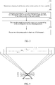
- FIG. 2 It is illustrated by taking FIG. 2 as examples.
- the user selects a panoramic boundary point A1 at first and also selects another panoramic boundary point A2.
- the electronic device can automatically calculate the number of shooting and position information of each shooting required to obtain the panoramic photograph.
- the electronic device only needs to shoot twice, wherein, two positions where the torsion module in the electronic device automatically stops are the positions as shown by B1 and B2 in FIG. 2 , the positions where the torsion module stops are the position information for shooting, and the areas of two shot photographs are D1 and D2 respectively.
- step 103 the at least two photographs are processed to obtain one panoramic photograph.
- the electronic device After shooting all photographs required to be shot, the electronic device processes the photographs obtained by shooting automatically, for example, the processing mode can be jointing, to obtain one panoramic photograph; the panoramic photograph includes all objects required to be shot in the area of selected shooting visual angle, and the objects can be shot quite clearly because the shootings are performed separately, which is convenient for the user to watch.
- the image processing module in the electronic device will process two photographs of which the areas are D1 and D2 automatically according to the current state (the shooting focal distance) and the shooting position, and the processing result may be to connect the coincident portion D3 of the two photographs, wherein, the connection mode can be: both D1 and D2 include D3, therefore the D3 of any photograph can be selected, or the D3 in D1 and the D3 in D2 can be superposed as well, so that they are combined into one layer.
- D1 (or D2) can be selected directly, and then D1 (or D2) and the area except the public portion D3 in D2 (or the area except the public portion D3 in D1) can be connected.
- the area of scene, combined and displayed finally, is the area between the top line and the bottom line in FIG. 2 .
- the electronic device can delete two shot photographs of which the areas are D1 and D2 respectively, in order to save the memory space.
- the panoramic photograph shooting method in the present invention is introduced through several embodiments hereinafter.
- Embodiment one the electronic device is a mobile phone, and the mobile phone is with a touch screen.
- the mobile phone has four modes during shooting, which are respectively the normal mode, the panoramic mode, the 3D mode and the video recording mode.
- the user selects the shooting focal distance as the first choice.
- the user selects the shooting mode as the panoramic mode and selects the first panoramic submode, that is, the panoramic photograph can be shot in the up-and-down direction, and meanwhile, the shooting visual angle has already been fixed, as the first preset shooting visual angle.
- the mobile phone After the shooting focal distance and the shooting visual angle are selected, the mobile phone starts to automatically calculate the number of shooting and position information of each shooting required to obtain the panoramic photograph; it is still illustrated by taking FIG. 2 as examples, the mobile phone calculates that it needs to shoot twice to obtain the panoramic photograph, and two shooting positions are the positions represented by B1 and B2 in FIG. 2 respectively.
- the torsion module in the mobile phone controls the lens assembly to turn to the position shown as B1 at first, shooting a photograph, and then the torsion module also controls the lens assembly to turn to the position shown as B2, shooting another photograph.
- the mobile phone After finishing the shooting, the mobile phone automatically processes two photographs obtained by shooting.
- the scene area of the first photograph is D1
- the scene area of the second photograph is D2
- the overlap portion of the two is D3.
- the D3 portion of any photograph can be selected; the mobile phone selects the D3 portion of the first photograph, and joints the two photographs, processing them to be one panoramic photograph, and the panoramic photograph includes all objects required to be shot in the area of selected visual angle.
- Embodiment two the electronic device is a mobile phone, and the mobile phone is with a touch screen.
- the mobile phone has four modes during shooting, which are respectively the normal mode, the panoramic mode, the 3D mode and the video recording mode.
- the user selects the shooting focal distance as the first choice.
- the user selects the shooting mode as the panoramic mode and selects the third panoramic submode, that is, the shooting visual angle can be selected by oneself. For example, the user wants to select to shoot the photographs in the left-and-right direction, as shown in FIG. 2 .
- the user can select the single boundary of the panoramic shooting through slipping a single finger on the touch screen; when the scene displayed on the touch screen reaches a panoramic boundary that the user wants to select, then the touch screen is clicked, which indicates that the current position is selected as a boundary point, that is, point A1 in FIG.
- the mobile phone After selecting two boundary points, the mobile phone starts to automatically calculate the number of shooting and position information of each shooting required to obtain the panoramic photograph; as shown in FIG. 2 , the mobile phone calculates that it needs to shoot twice to obtain the panoramic photograph, and two shooting positions are the positions represented by B1 and B2 in FIG. 2 respectively.
- the calculation time of the mobile phone can be neglected, and the user can click the corresponding button on the touch screen again after selecting two boundary points, and then the mobile phone shoots the panoramic photograph automatically.
- the torsion module in the mobile phone controls the lens assembly to turn to the position shown as B1 at first, shooting one photograph, and then the torsion module also controls the lens assembly to turn to the position shown as B2, shooting another photograph.
- the mobile phone After finishing the shooting, the mobile phone automatically processes two photographs obtained by shooting.
- the scene area of the first photograph is D1
- the scene area of the second photograph is D2
- the overlap portion of the two is D3.
- the D3 portion of any photograph can be selected, and the mobile phone selects to perform superposition processing on the D3 portions of two photographs and process them as one layer, and then it joints two photographs, processing them to be one panoramic photograph, and the panoramic photograph includes all objects required to be shot in the area of selected visual angle.
- the embodiment of the present invention further provides a photograph shooting method, which can be applied in an electronic device with a lens assembly, and the main procedures of the method is as follows.
- step 301 a shooting focal distance and an initial position of the lens assembly are determined.
- the electronic device can have many kinds of shooting modes, for example, it can have a normal mode, a panoramic mode, a 3D mode, a video recording mode, etc., the user can shoot normally in the normal mode, shoot the panoramic photograph in the panoramic mode, shoot the 3D photo in the 3D mode and record a video in the video recording mode.
- the shooting mode can be determined at first. What the present embodiment introduces is the 3D photograph shooting method, and therefore, the shooting mode can be determined as the 3D mode at first.
- the initial position of the lens assembly is the position as shown by C1.
- step 302 information of two shooting positions for shooting two photographs used for obtaining a 3D photograph is determined according to the initial position of the lens assembly.
- the shooting position refers to the position where the lens assembly is located during the shooting.
- the users selects the shooting focal distance and determines the initial position of the lens assembly as the position shown by C1, that is, the 3D image area required to be obtained, then the electronic device can automatically calculate the positions where two shootings are located according to the current shooting focal distance and the initial position of the lens assembly.
- the positions where the two shootings are located can be laid out symmetrically by taking the initial position of the lens assembly as the center, which makes the images presented at such two positions are consistent with the images that are presented by people observing the objects through eyes as possible, in order to make the effect of the obtained 3D photograph better; for example, other two shooting positions are the positions shown by C2 and C3 respectively.
- step 303 one photograph is shot respectively at positions corresponding to the information of the two shooting positions.
- the torsion module in the mobile phone controls the lens assembly to turn to the position shown as C2 at first, shooting one photograph, and then the torsion module also controls the lens assembly to turn to the position shown as C3, shootings another photograph.
- the area covered by the first photograph is D1
- the area covered by the second photograph is D2.
- step 304 two shot photographs are processed to obtain a 3D photograph.
- the image processing module in the electronic device can process these two photographs, for example, the processing mode can be superposition or other processing modes, to finish composing the 3D photograph, and the area covered by the finally obtained 3D photograph is the D3 area in FIG. 4 .
- FIG. 4 also shows a D4 area; if shooting is performed at the initial position of the lens assembly, then the area covered by the shot photograph is the D4 area, and the D3 area is obviously slightly smaller than the D4 area. At the boundary of the D3 area and the D4 area, its effect is not 3D effect, but it can generally be neglected. Alternatively, while selecting the D4 area, it can be selected a bit greater through appropriate focusing, thus the D3 area become larger correspondingly as well, which will not produce great influence on the final 3D effect. In fact, after selecting the 3D mode, what the display directly displays is the scene range of the 3D photograph that will be finished finally, such as D3 in FIG. 4 .
- the electronic device can delete two temporary photographs in the shooting process, that is, the two photographs of which the covered areas are D1 and D2 respectively, in order to save the memory space.
- the 3D photograph shooting method in the embodiment of the present invention is introduced through several embodiments hereinafter.
- Embodiment three the electronic device is a mobile phone, and the mobile phone is with a touch screen.
- the mobile phone has four modes during shooting, which are respectively the normal mode, the panoramic mode, the 3D mode and the video recording mode.
- the user selects the shooting focal distance at first and selects the shooting mode as the 3D mode.
- the user determines the initial position of the lens assembly, and it is illustrated by taking FIG. 4 as examples, and the initial position of the lens assembly is the C1 position as shown in FIG. 4 .
- the electronic device can automatically calculate the positions where two shootings are located according to the current shooting focal distance and the initial position of the lens assembly.
- the positions where the two shootings are located can be laid out symmetrically by taking the initial position of the lens assembly as the center, which makes the images presented at such two positions are consistent with the images that are presented by people observing the objects through eyes as possible, for example, other two shooting positions are the positions shown by C2 and C3 respectively.
- the torsion module in the mobile phone controls the lens assembly to turn to the position shown as C1 at first, shooting one photograph, and then the torsion module also controls the lens assembly to turn to the position shown as C2, shooting another photograph.
- the area covered by the first photograph is D1
- the area covered by the second photograph is D2.
- the image processing module in the electronic device can process these two photographs, and the processing mode in the embodiment of the present invention can be superposition, or other processing modes, to finish composing the 3D photograph, and the area covered by the finally obtained 3D photograph is the D3 area in FIG. 4 .
- the electronic device can delete two temporary photographs in the shooting process, that is, two photographs of which the covered areas are D1 and D2 respectively.
- the electronic device of the embodiment of the present invention can include a first determination module 501, an imaging module 502 and an image processing module 503.
- the first determination module 501 is configured to: determine a shooting focal distance and a shooting visual angle.
- the first determination module 501 is configured to: determine a shooting focal distance and a shooting visual angle by the following way: determining the shooting focal distance and a shooting mode according to a selection of a user, and determining the shooting visual angle according to the shooting mode.
- the first determination module 501 is further configured to: shoot at least two photographs according to the determined number of photographs required to be shot and position of each shooting.
- the imaging module 502 is configured to: shoot at least two photographs, comprising all objects required to be shot in an area of the shooting visual angle, according to the shooting focal distance and the shooting visual angle which are determined; and The imaging module 502 is further configured to: shoot photographs of which the number is equal to the number of photographs required to be shot according to the determined number of photographs required to be shot.
- the imaging module 502 can include the lens assembly and an imaging unit, and the objects shot by the lens assembly are imaged on the imaging unit.
- the imaging unit can be connected with the lens assembly.
- the image processing module 503 is configured to: process the at least two photographs to obtain one panoramic photograph.
- the image processing module 503 is configured to: process the at least two photographs to obtain one panoramic photograph by the following way: jointing the at least two photographs, to obtain one panoramic photograph; and when the at least two photographs have overlap portions, and when jointing the at least two photographs, select the overlap portion of any photograph in the at least two photographs, or superpose the overlap portions of the two photographs, to process them as one layer.
- the electronic device can further include a torsion module 504, and the torsion module 504 is configured to: make the lens assembly rotated to corresponding positions to shoot respectively according to the determined position information of each shooting.
- the torsion module 504 when the torsion module 504 turns the lens assembly, it also can make the imaging unit turn together with the lens assembly at the same time, in order to obtain the better shooting effect.
- the electronic device can further include a second determination module 505, and the second determination module 505 is configured to: determine the number of photographs required to be shot and position information of each shooting respectively according to the shooting focal distance and the shooting visual angle which are determined.
- the embodiment of the present invention further provides an electronic device, which can includes a first determination module 501, a second determination module 505, an imaging module 502 and an image processing module 503, and the electronic device can further include a torsion module 504.
- the electronic device can be the same as the electronic device shown in FIG. 5 .
- the first determination module 501 is configured to: determine a shooting focal distance and an initial position of the lens assembly;
- the second determination module 505 is configured to: determine information of two shooting positions for shooting two photographs used for obtaining a 3D photograph according to the initial position of the lens assembly;
- the imaging module 502 is configured to: shoot one photograph respectively at positions corresponding to the information of the two shooting positions.
- the imaging module 502 can be configured to shoot one photograph respectively at positions corresponding to the information of the two shooting positions according the following way: shooting the photograph at a position where the lens assembly stops, that it, shooting one photograph at the corresponding positions respectively.
- the corresponding positions refer to the positions to which the lens assembly is made to turn respectively by the torsion module 504 according to the determined information of other two shooting positions.
- the imaging module 502 can include the lens assembly and the imaging unit, and the objects shot by the lens assembly are imaged on the imaging unit.
- the imaging unit can be connected with the lens assembly.
- the image processing module 503 is configured to: process two shot photographs to obtain one 3D photograph.
- the torsion module 504 is configured to: make the lens assembly rotated to corresponding positions respectively according to the determined information of other two shooting positions; and the lens assembly shoots one photograph respectively at the positions corresponding to the information of the two shooting positions.
- the torsion module 504 when the torsion module 504 turns the lens assembly, it also can make the imaging unit turn together with the lens assembly at the same time, in order to obtain the better shooting effect.
- the embodiment of present invention provides a specific photograph shooting method.
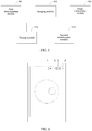
- buttons on the touch screen in FIG. 6 which are indicated by Arabic numerals 1, 2, 3, 4 in FIG. 6 and respectively represent the 3D mode, the panoramic mode, the normal mode and the video recording mode in the shooting modes.
- the greater circular frame represents the magnification, which can be changed through focusing
- the smaller circular frame represents the angle or orientation turned by the lens assembly
- the center position of the smaller circle in the present embodiment is contrary to the turning direction of the lens assembly, for example, if the center of the smaller circle is right under the center of the greater circle, then it represents that the lens assembly is corresponding to the upper area relative to the horizontal orientation.
- the greater circle in FIG. 6 is indicated by dotted line, and the smaller circle is indicated by dash line.
- the present embodiment is only to provide an embodiment, and only used to explain the present invention, rather than limiting the present invention.
- the photograph shooting method in the embodiment of the present invention includes: determining a shooting focal distance and a shooting visual angle; the lens assembly automatically shooting at least two photographs, including all objects required to be shot in an area of the shooting visual angle, according to the shooting focal distance and the shooting visual angle which are determined; and processing the at least two photographs to obtain one panoramic photograph.
- the electronic device can perform shooting automatically, and it can shoot at least two photographs automatically, and then processes the shot photograph, to obtain one panoramic photograph, thus providing a panoramic photograph shooting method, in order to shoot all objects in the selected area clearly, and further obtain the panoramic photograph with a better effect.
- the mobile phone in the related art needs to shoot the panoramic photograph manually, the effect of the panoramic photograph obtained in this way is definitely not very ideal, while the electronic device in the embodiment of the present invention, after the user selects the shooting focal distance and the shooting visual angle, can obtain the photographs required to be shot and position information of shooting each photograph automatically for shooting one panoramic photograph , and it can shoot automatically, and it can compose the photograph obtained by shooting to be one panoramic photograph automatically after finishing the shooting, so that the obtained panoramic photograph is less influenced by the human factor, and the effect is better. And after obtaining the panoramic photograph, it can delete the single shot photograph, in order to save the memory space.
- the mobile phone in the related art is unable to shoot the 3D photograph, while in the embodiment of the present invention, the electronic device can calculate the position information for shooting other two photographs automatically according to the determined initial position of the lens assembly, and these other two photographs are two photographs which can be composed to be the 3D photograph; the electronic device can shoot automatically according to the calculation result, and the two photographs obtained by shooting can be composed to be the 3D photograph automatically after finishing the shooting, and when determining other two positions, the images presented at such two positions are made to be consistent with the images that are presented by people observing the objects through eyes as possible, in order to make the effect of the obtained 3D photograph better. And after obtaining the 3D photograph, it can delete the single shot photograph, in order to save the memory space.
- the embodiment of the present invention can provide a method, system, or computer program product. So, the embodiment of the present invention can adopt forms of a complete hardware embodiment, a complete software embodiment, or an embodiment combining software and hardware aspects. And, the embodiment of the present invention can adopt the form of the computer program product implemented on one or more storage mediums usable for the computer (including but not limited to the magnetic disc memory and the optical memory, etc.), including the program code usable for the computer.
- the present invention is described according to the method, device (system), and the flow chart and/or the block diagram of the computer program product in the embodiment of the present invention. It should be understood that every procedure and/or block in the flow chart and/or the block diagram, and the combination of the procedure and/or block in the flow chart and/or the block diagram can be realized by the computer program command.
- These computer program commands can be provided to a general-purpose computer, a special purpose computer, an embedded processor or a processor of other programmable data processing equipment to produce a machine, so that the commands executed through the computer or the processor of other programmable data processing equipment produce an apparatus used for realizing the function specified in one procedure or multiple procedures of the flow chart and/or one block or multiple blocks of the block diagram.
- These computer program commands also can be stored in the computer readable storage which can lead the computer or other programmable data processing equipment to work in a particular way, so that the commands stored in the computer readable storage produce the manufacturing products including the command apparatus, and the command apparatus realizes the function specified in one procedure or multiple procedures of the flow chart and/or one block or multiple blocks of the block diagram.
Landscapes
- Physics & Mathematics (AREA)
- General Physics & Mathematics (AREA)
- Engineering & Computer Science (AREA)
- Multimedia (AREA)
- Signal Processing (AREA)
- Studio Devices (AREA)
- Stereoscopic And Panoramic Photography (AREA)
Claims (6)
- Verfahren zum Aufnehmen eines Panoramafotos, das in einer elektronischen Vorrichtung mit einer Linsenanordnung angewendet wird, das Folgendes umfasst:
Festlegen einer Aufhahmenbrennweite und eines Aufnahmeblickwinkels (101); wobei das Festlegen einer Aufhahmenbrennweite und eines Aufnahmeblickwinkels Folgendes umfasst:Festlegen der Aufnahmenbrennweite und einer von einer Vielzahl von Panoramaaufhahmemodi gemäß einer Auswahl eines Benutzers und Festlegendes Aufnahmeblickwinkels gemäß dem ausgewählten Panoramaaufhahmemodus;Aufnehmen von mindestens zwei Fotos über die Linsenanordnung, die alle Objekte umfasst, die in einem Bereich des Aufnahmeblickwinkels gemäß der Aufnahmenbrennweite und dem Aufnahmeblickwinkel, die festgelegt (102) sind, aufgenommen werden müssen; undVerarbeiten der mindestens zwei Fotos, um ein Panoramafoto (103) zu erhalten;vor dem Aufnehmen von mindestens zwei Fotos gemäß der Aufhahmenbrennweite und dem Aufnahmeblickwinkel, die festgelegt sind, automatisches Festlegen der Anzahl von Fotos, die aufgenommen werden müssen, und der Positionsinformationen von jeweils jeder Aufnahme gemäß der Aufnahmenbrennweite und dem Aufnahmeblickwinkel, die festgelegt sind;wobei das Aufnehmen der mindestens zwei Fotos gemäß der Aufhahmenbrennweite und dem Aufnahmeblickwinkel, die festgelegt sind, Folgendes umfasst: ein Torsionsmodul in der elektronischen Vorrichtung,das bewirkt, dass sich die Linsenanordnung an eine entsprechende Position dreht, um gemäß den festgelegten Positionsinformationen jeder Aufnahme aufzunehmen und Aufnehmen von Fotos,von denen die Anzahl gleich der Anzahl von Fotos, die aufgenommen werden müssen, ist, die gemäß der festgelegten Anzahl von Fotos aufgenommen werden müssen. - Verfahren nach Anspruch 1, wobei das Verarbeiten der mindestens zwei Fotos, um ein Foto zu erhalten, Folgendes umfasst:
Verbinden der mindestens zwei Fotos, um ein Panoramafoto zu erhalten. - Verfahren nach Anspruch 2, wobei das Verbinden der mindestens zwei Fotos Folgendes umfasst:
wenn die mindestens zwei Fotos einen Überlappungsabschnitt aufweisen, Auswählen des Überlappungsabschnitts von einem Foto in den mindestens zwei Fotos oder Überlagern des Überlappungsabschnitts der mindestens zwei Fotos. - Elektronische Vorrichtung mit einer Linsenanordnung, wobei die elektronische Vorrichtung ferner ein erstes Festlegungsmodul (501), ein Abbildungsmodul (502), ein Bildverarbeitungsmodul (503) und ein zweites Festlegungsmodul (505) umfasst, wobei:das erste Festlegungsmodul (501) zu Folgendem konfiguriert ist: Festlegen einer Aufnahmenbrennweite und eines Aufnahmeblickwinkels (101); wobei das Festlegen einer Aufnahmenbrennweite und eines Aufnahmeblickwinkels Folgendes umfasst: Festlegen der Aufnahmenbrennweite und einer von einer Vielzahl von Panoramaaufnahmemodi gemäß einer Auswahl eines Benutzers und Festlegen des Aufnahmeblickwinkels gemäß dem ausgewählten Panoramaaufnahmemodus;das Abbildungsmodul (502) zu Folgendem konfiguriert ist: Aufnehmen von mindestens zwei Fotos über die Linsenanordnung, die alle Objekte umfasst, die in einem Bereich des Aufnahmeblickwinkels gemäß der Aufnahmenbrennweite und dem Aufnahmeblickwinkel, die festgelegt sind, aufgenommen werden müssen;
unddas Bildverarbeitungsmodul (503) zu Folgendem konfiguriert ist: Verarbeiten der mindestens zwei Fotos, um ein Panoramafoto zu erhalten;das zweite Festlegungsmodul (505) zu Folgendem konfiguriert ist: automatisches Festlegen der Anzahl von Fotos, die aufgenommen werden müssen, und der Positionsinformationen von jeder Aufnahme jeweils gemäß der Aufnahmenbrennweite und dem Aufnahmeblickwinkel, die festgelegt sind; wobei das erste Festlegungsmodul (501) zu Folgendem konfiguriert ist: Festlegen einer Aufnahmenbrennweite und eines Aufnahmeblickwinkel auf eine folgende Weise: Festlegen der Aufhahmenbrennweite und eines Aufnahmemodus gemäß einer Auswahl eines Benutzers und Festlegen des Aufnahmeblickwinkels gemäß dem Aufnahmemodul;wobei die Vorrichtung ferner ein Torsionsmodul umfasst, wobei:das Torsionsmodul zu Folgendem konfiguriert ist: Bewirken, dass sich die Linsenanordnung an entsprechende Positionen dreht, um jeweils gemäß der festgelegten Positionsinformationen jeder Aufnahme aufzunehmen unddas Bildgebungsmodul ferner zu Folgendem konfiguriert ist: Aufnehmen von Fotos, deren Anzahl gleich der Anzahl von Fotos, die aufgenommen werden müssen, gemäß der festgelegten Anzahl von Fotos ist, die aufgenommen werden müssen. - Elektronische Vorrichtung nach Anspruch 4, wobei das Bildverarbeitungsmodul (503) zu Folgendem konfiguriert ist:
Verarbeiten der mindestens zwei Fotos, um ein Panoramafoto auf eine folgende Weise zu erhalten:
Verbinden der mindestens zwei Fotos, um ein Panoramafoto zu erhalten. - Elektronische Vorrichtung nach Anspruch 5, wobei das Bildverarbeitungsmodul (503) ferner zu Folgendem konfiguriert ist:
wenn die mindestens zwei Fotos einen Überlappungsabschnitt aufweisen, Auswählen eines Überlappungsabschnitts von einem Foto in den mindestens zwei Fotos oder Überlagern des Überlappungsabschnitts von zwei Fotos.
Applications Claiming Priority (2)
| Application Number | Priority Date | Filing Date | Title |
|---|---|---|---|
| CN2012101186070A CN102645836A (zh) | 2012-04-20 | 2012-04-20 | 一种照片拍摄方法及电子设备 |
| PCT/CN2012/078754 WO2013155804A1 (zh) | 2012-04-20 | 2012-07-17 | 一种照片拍摄方法及电子设备 |
Publications (3)
| Publication Number | Publication Date |
|---|---|
| EP2840445A1 EP2840445A1 (de) | 2015-02-25 |
| EP2840445A4 EP2840445A4 (de) | 2015-11-18 |
| EP2840445B1 true EP2840445B1 (de) | 2018-09-05 |
Family
ID=46658734
Family Applications (1)
| Application Number | Title | Priority Date | Filing Date |
|---|---|---|---|
| EP12874817.5A Active EP2840445B1 (de) | 2012-04-20 | 2012-07-17 | Fotografierverfahren und elektronische vorrichtung |
Country Status (4)
| Country | Link |
|---|---|
| US (1) | US9900506B2 (de) |
| EP (1) | EP2840445B1 (de) |
| CN (1) | CN102645836A (de) |
| WO (1) | WO2013155804A1 (de) |
Families Citing this family (21)
| Publication number | Priority date | Publication date | Assignee | Title |
|---|---|---|---|---|
| CN103297694B (zh) * | 2013-05-20 | 2016-09-14 | 深圳市金立通信设备有限公司 | 一种全景拍摄的方法及设备 |
| KR101946437B1 (ko) | 2013-12-13 | 2019-02-11 | 후아웨이 디바이스 컴퍼니 리미티드 | 파노라마 이미지 획득을 위한 방법 및 단말기 |
| CN105282417A (zh) * | 2014-06-20 | 2016-01-27 | 宇龙计算机通信科技(深圳)有限公司 | 一种超像素拍摄实现方法、装置及终端设备 |
| CN105472234B (zh) * | 2014-09-10 | 2019-04-05 | 中兴通讯股份有限公司 | 一种照片显示方法及装置 |
| CN104284093B (zh) * | 2014-10-22 | 2018-09-18 | 小米科技有限责任公司 | 全景拍摄方法及装置 |
| CN104796615B (zh) * | 2015-04-27 | 2018-12-07 | 惠州Tcl移动通信有限公司 | 一种ois防抖马达的大像素拍摄方法、系统及移动终端 |
| CN104954679B (zh) * | 2015-06-16 | 2018-03-23 | 青岛海信移动通信技术股份有限公司 | 一种图片拍摄的控制方法、装置及终端 |
| CN105120179B (zh) * | 2015-09-22 | 2019-01-11 | 三星电子(中国)研发中心 | 一种拍照方法和装置 |
| CN105338244B (zh) * | 2015-10-30 | 2019-04-16 | 努比亚技术有限公司 | 一种信息处理方法及移动终端 |
| CN105430265A (zh) * | 2015-11-27 | 2016-03-23 | 努比亚技术有限公司 | 一种增大摄像头成像范围的方法及装置 |
| CN107295327B (zh) * | 2016-04-05 | 2019-05-10 | 富泰华工业(深圳)有限公司 | 光场相机及其控制方法 |
| CN106155593B (zh) * | 2016-08-01 | 2019-09-24 | 惠州Tcl移动通信有限公司 | 一种基于拍摄质量删除照片的方法及系统 |
| CN106210405A (zh) * | 2016-08-31 | 2016-12-07 | 上海高智科技发展有限公司 | 图像复制设备、方法及装置 |
| KR20180039529A (ko) * | 2016-10-10 | 2018-04-18 | 엘지전자 주식회사 | 이동 단말기 및 그의 동작 방법 |
| CN107465907B (zh) * | 2017-08-16 | 2019-08-20 | 维沃移动通信有限公司 | 一种拍摄方法及移动终端 |
| CN108449546B (zh) * | 2018-04-04 | 2020-03-31 | 维沃移动通信有限公司 | 一种拍照方法及移动终端 |
| CN110291777B (zh) * | 2018-04-09 | 2021-09-14 | 深圳市大疆创新科技有限公司 | 图像采集方法、设备及机器可读存储介质 |
| CN108810201B (zh) | 2018-06-04 | 2020-07-17 | Oppo广东移动通信有限公司 | 电子装置及利用电子装置拍摄照片的方法 |
| CN110771138B (zh) * | 2018-07-27 | 2022-08-30 | 深圳市大疆创新科技有限公司 | 全景拍摄的控制方法及控制装置、成像系统和存储介质 |
| CN112822478B (zh) * | 2020-12-31 | 2022-10-18 | 杭州电子科技大学 | 一种用于三维重建的高质量照片序列获取方法 |
| CN113114819B (zh) * | 2021-04-20 | 2023-09-01 | Oppo广东移动通信有限公司 | 全景拍摄方法、电子装置和可读存储介质 |
Family Cites Families (17)
| Publication number | Priority date | Publication date | Assignee | Title |
|---|---|---|---|---|
| US4754327A (en) * | 1987-03-20 | 1988-06-28 | Honeywell, Inc. | Single sensor three dimensional imaging |
| JP3021556B2 (ja) * | 1990-06-20 | 2000-03-15 | ソニー株式会社 | 映像情報処理装置とその方法 |
| JPH09171221A (ja) * | 1995-12-20 | 1997-06-30 | Minolta Co Ltd | 立体画像形成装置 |
| US6094215A (en) * | 1998-01-06 | 2000-07-25 | Intel Corporation | Method of determining relative camera orientation position to create 3-D visual images |
| JP2000295504A (ja) | 1999-04-06 | 2000-10-20 | Canon Inc | デジタルカメラ |
| JP4356689B2 (ja) * | 2005-12-08 | 2009-11-04 | ソニー株式会社 | カメラシステム、カメラ制御装置、パノラマ画像作成方法及びコンピュータ・プログラム |
| CN100517061C (zh) * | 2006-01-24 | 2009-07-22 | 鸿富锦精密工业(深圳)有限公司 | 全景影像的产生装置及方法 |
| CN100432836C (zh) * | 2006-05-19 | 2008-11-12 | 李鹏 | 实现二维全景真实成像的方法 |
| JP2007334558A (ja) | 2006-06-14 | 2007-12-27 | Sony Corp | 画像処理装置および方法、並びにプログラム |
| JP2009049854A (ja) | 2007-08-22 | 2009-03-05 | Fujifilm Corp | 複眼撮影装置 |
| KR101354899B1 (ko) * | 2007-08-29 | 2014-01-27 | 삼성전자주식회사 | 파노라마 사진 촬영 방법 |
| CN101420525A (zh) * | 2007-10-26 | 2009-04-29 | 鸿富锦精密工业(深圳)有限公司 | 拍照装置及方法 |
| CN101534413B (zh) * | 2009-04-14 | 2012-07-04 | 华为终端有限公司 | 一种远程呈现的系统、装置和方法 |
| CN102033415B (zh) | 2009-09-27 | 2013-01-30 | 深圳市掌网立体时代视讯技术有限公司 | 立体数码成像同步装置和方法 |
| JP5163676B2 (ja) * | 2010-03-19 | 2013-03-13 | カシオ計算機株式会社 | 撮像装置、撮像方法及びプログラム |
| CN101968602B (zh) * | 2010-07-27 | 2011-08-17 | 北京迪生动画科技有限公司 | 一种单路相机模拟双路相机实现立体影像拍摄的系统 |
| JP5506589B2 (ja) * | 2010-08-02 | 2014-05-28 | キヤノン株式会社 | 撮像装置及びその制御方法、プログラム、並びに記録媒体 |
-
2012
- 2012-04-20 CN CN2012101186070A patent/CN102645836A/zh active Pending
- 2012-07-17 EP EP12874817.5A patent/EP2840445B1/de active Active
- 2012-07-17 WO PCT/CN2012/078754 patent/WO2013155804A1/zh not_active Ceased
- 2012-07-17 US US14/395,174 patent/US9900506B2/en active Active
Non-Patent Citations (1)
| Title |
|---|
| None * |
Also Published As
| Publication number | Publication date |
|---|---|
| WO2013155804A1 (zh) | 2013-10-24 |
| US9900506B2 (en) | 2018-02-20 |
| US20150103139A1 (en) | 2015-04-16 |
| CN102645836A (zh) | 2012-08-22 |
| EP2840445A4 (de) | 2015-11-18 |
| EP2840445A1 (de) | 2015-02-25 |
Similar Documents
| Publication | Publication Date | Title |
|---|---|---|
| US9900506B2 (en) | Method and electronic device for shooting panoramic photograph | |
| JP6106764B2 (ja) | 撮像装置及びタイムラプス撮像方法 | |
| US8416282B2 (en) | Camera for creating a panoramic image | |
| CN107005675B (zh) | 动态图像编辑装置、动态图像编辑方法及存储介质 | |
| EP2590421B1 (de) | Einzelobjektiv-vorrichtung zur erfassung stereoskopischer bilder | |
| US20120300051A1 (en) | Imaging apparatus, and display method using the same | |
| JP6286668B2 (ja) | 撮像装置および撮像画像の表示方法 | |
| US8730377B2 (en) | Imaging apparatus adjusting autofocus position based on stored adjustment amount | |
| JP6833801B2 (ja) | 撮像装置、撮像方法、プログラムおよび記録媒体 | |
| CN102511013A (zh) | 摄像装置及其控制方法和程序 | |
| JP2009054130A (ja) | 画像処理装置、画像処理方法およびデジタルスチルカメラ | |
| US9609224B2 (en) | Imaging device and image display method | |
| JP2014143545A (ja) | 撮影機器 | |
| JP2007295547A (ja) | デジタルカメラ | |
| US10587809B2 (en) | Continuous shooting device, continuous shooting method and continuous shooting control method using preliminary and calculated parameter values | |
| KR20140121695A (ko) | 촬영 장치 및 촬영 제어 방법 | |
| CN115379075A (zh) | 月亮拍摄方法、装置、存储介质及拍摄设备 | |
| JP4565909B2 (ja) | カメラ | |
| US20140368698A1 (en) | Display control apparatus, display control method, program, and image pickup apparatus | |
| JP2002158919A (ja) | 撮像装置及び画像取得ステップ | |
| JP2010041365A (ja) | 撮像装置 | |
| JP2005328497A (ja) | 撮像装置及び撮像方法 | |
| JP6745682B2 (ja) | 撮像装置、制御方法、プログラム、及び記憶媒体 | |
| KR20130024021A (ko) | 디지털 촬영 장치 및 이의 제어 방법 | |
| JP5293282B2 (ja) | デジタルカメラの撮影方法及びデジタルカメラ |
Legal Events
| Date | Code | Title | Description |
|---|---|---|---|
| PUAI | Public reference made under article 153(3) epc to a published international application that has entered the european phase |
Free format text: ORIGINAL CODE: 0009012 |
|
| 17P | Request for examination filed |
Effective date: 20141017 |
|
| AK | Designated contracting states |
Kind code of ref document: A1 Designated state(s): AL AT BE BG CH CY CZ DE DK EE ES FI FR GB GR HR HU IE IS IT LI LT LU LV MC MK MT NL NO PL PT RO RS SE SI SK SM TR |
|
| AX | Request for extension of the european patent |
Extension state: BA ME |
|
| RIC1 | Information provided on ipc code assigned before grant |
Ipc: G03B 35/04 20060101ALI20150601BHEP Ipc: H04N 5/238 20060101ALI20150601BHEP Ipc: H04N 13/00 20060101ALI20150601BHEP Ipc: H04N 5/232 20060101ALI20150601BHEP Ipc: H04N 13/02 20060101ALI20150601BHEP Ipc: G03B 37/02 20060101ALI20150601BHEP Ipc: G03B 37/00 20060101AFI20150601BHEP Ipc: G03B 5/00 20060101ALI20150601BHEP Ipc: G03B 35/00 20060101ALI20150601BHEP |
|
| DAX | Request for extension of the european patent (deleted) | ||
| RIC1 | Information provided on ipc code assigned before grant |
Ipc: H04N 5/238 20060101ALI20151007BHEP Ipc: H04N 13/00 20060101ALI20151007BHEP Ipc: G03B 35/00 20060101ALI20151007BHEP Ipc: G03B 37/02 20060101ALI20151007BHEP Ipc: H04N 5/232 20060101ALI20151007BHEP Ipc: G03B 37/00 20060101AFI20151007BHEP Ipc: H04N 13/02 20060101ALI20151007BHEP Ipc: G03B 35/04 20060101ALI20151007BHEP Ipc: G03B 5/00 20060101ALI20151007BHEP |
|
| RA4 | Supplementary search report drawn up and despatched (corrected) |
Effective date: 20151016 |
|
| STAA | Information on the status of an ep patent application or granted ep patent |
Free format text: STATUS: EXAMINATION IS IN PROGRESS |
|
| 17Q | First examination report despatched |
Effective date: 20170810 |
|
| GRAP | Despatch of communication of intention to grant a patent |
Free format text: ORIGINAL CODE: EPIDOSNIGR1 |
|
| STAA | Information on the status of an ep patent application or granted ep patent |
Free format text: STATUS: GRANT OF PATENT IS INTENDED |
|
| RIC1 | Information provided on ipc code assigned before grant |
Ipc: H04N 5/238 20060101ALI20180223BHEP Ipc: H04N 13/00 20060101ALI20180223BHEP Ipc: G03B 5/00 20060101ALI20180223BHEP Ipc: G03B 35/00 20060101ALI20180223BHEP Ipc: H04N 5/232 20060101ALI20180223BHEP Ipc: G03B 35/04 20060101ALI20180223BHEP Ipc: G03B 37/00 20060101AFI20180223BHEP Ipc: G03B 37/02 20060101ALI20180223BHEP |
|
| INTG | Intention to grant announced |
Effective date: 20180403 |
|
| GRAS | Grant fee paid |
Free format text: ORIGINAL CODE: EPIDOSNIGR3 |
|
| GRAA | (expected) grant |
Free format text: ORIGINAL CODE: 0009210 |
|
| STAA | Information on the status of an ep patent application or granted ep patent |
Free format text: STATUS: THE PATENT HAS BEEN GRANTED |
|
| AK | Designated contracting states |
Kind code of ref document: B1 Designated state(s): AL AT BE BG CH CY CZ DE DK EE ES FI FR GB GR HR HU IE IS IT LI LT LU LV MC MK MT NL NO PL PT RO RS SE SI SK SM TR |
|
| REG | Reference to a national code |
Ref country code: GB Ref legal event code: FG4D |
|
| REG | Reference to a national code |
Ref country code: CH Ref legal event code: EP |
|
| REG | Reference to a national code |
Ref country code: AT Ref legal event code: REF Ref document number: 1038524 Country of ref document: AT Kind code of ref document: T Effective date: 20180915 |
|
| REG | Reference to a national code |
Ref country code: IE Ref legal event code: FG4D |
|
| REG | Reference to a national code |
Ref country code: DE Ref legal event code: R096 Ref document number: 602012050839 Country of ref document: DE |
|
| REG | Reference to a national code |
Ref country code: NL Ref legal event code: MP Effective date: 20180905 |
|
| REG | Reference to a national code |
Ref country code: LT Ref legal event code: MG4D |
|
| PG25 | Lapsed in a contracting state [announced via postgrant information from national office to epo] |
Ref country code: GR Free format text: LAPSE BECAUSE OF FAILURE TO SUBMIT A TRANSLATION OF THE DESCRIPTION OR TO PAY THE FEE WITHIN THE PRESCRIBED TIME-LIMIT Effective date: 20181206 Ref country code: NO Free format text: LAPSE BECAUSE OF FAILURE TO SUBMIT A TRANSLATION OF THE DESCRIPTION OR TO PAY THE FEE WITHIN THE PRESCRIBED TIME-LIMIT Effective date: 20181205 Ref country code: BG Free format text: LAPSE BECAUSE OF FAILURE TO SUBMIT A TRANSLATION OF THE DESCRIPTION OR TO PAY THE FEE WITHIN THE PRESCRIBED TIME-LIMIT Effective date: 20181205 Ref country code: FI Free format text: LAPSE BECAUSE OF FAILURE TO SUBMIT A TRANSLATION OF THE DESCRIPTION OR TO PAY THE FEE WITHIN THE PRESCRIBED TIME-LIMIT Effective date: 20180905 Ref country code: LT Free format text: LAPSE BECAUSE OF FAILURE TO SUBMIT A TRANSLATION OF THE DESCRIPTION OR TO PAY THE FEE WITHIN THE PRESCRIBED TIME-LIMIT Effective date: 20180905 Ref country code: RS Free format text: LAPSE BECAUSE OF FAILURE TO SUBMIT A TRANSLATION OF THE DESCRIPTION OR TO PAY THE FEE WITHIN THE PRESCRIBED TIME-LIMIT Effective date: 20180905 Ref country code: SE Free format text: LAPSE BECAUSE OF FAILURE TO SUBMIT A TRANSLATION OF THE DESCRIPTION OR TO PAY THE FEE WITHIN THE PRESCRIBED TIME-LIMIT Effective date: 20180905 |
|
| REG | Reference to a national code |
Ref country code: AT Ref legal event code: MK05 Ref document number: 1038524 Country of ref document: AT Kind code of ref document: T Effective date: 20180905 |
|
| PG25 | Lapsed in a contracting state [announced via postgrant information from national office to epo] |
Ref country code: AL Free format text: LAPSE BECAUSE OF FAILURE TO SUBMIT A TRANSLATION OF THE DESCRIPTION OR TO PAY THE FEE WITHIN THE PRESCRIBED TIME-LIMIT Effective date: 20180905 Ref country code: LV Free format text: LAPSE BECAUSE OF FAILURE TO SUBMIT A TRANSLATION OF THE DESCRIPTION OR TO PAY THE FEE WITHIN THE PRESCRIBED TIME-LIMIT Effective date: 20180905 Ref country code: HR Free format text: LAPSE BECAUSE OF FAILURE TO SUBMIT A TRANSLATION OF THE DESCRIPTION OR TO PAY THE FEE WITHIN THE PRESCRIBED TIME-LIMIT Effective date: 20180905 |
|
| PG25 | Lapsed in a contracting state [announced via postgrant information from national office to epo] |
Ref country code: PL Free format text: LAPSE BECAUSE OF FAILURE TO SUBMIT A TRANSLATION OF THE DESCRIPTION OR TO PAY THE FEE WITHIN THE PRESCRIBED TIME-LIMIT Effective date: 20180905 Ref country code: AT Free format text: LAPSE BECAUSE OF FAILURE TO SUBMIT A TRANSLATION OF THE DESCRIPTION OR TO PAY THE FEE WITHIN THE PRESCRIBED TIME-LIMIT Effective date: 20180905 Ref country code: EE Free format text: LAPSE BECAUSE OF FAILURE TO SUBMIT A TRANSLATION OF THE DESCRIPTION OR TO PAY THE FEE WITHIN THE PRESCRIBED TIME-LIMIT Effective date: 20180905 Ref country code: IS Free format text: LAPSE BECAUSE OF FAILURE TO SUBMIT A TRANSLATION OF THE DESCRIPTION OR TO PAY THE FEE WITHIN THE PRESCRIBED TIME-LIMIT Effective date: 20190105 Ref country code: IT Free format text: LAPSE BECAUSE OF FAILURE TO SUBMIT A TRANSLATION OF THE DESCRIPTION OR TO PAY THE FEE WITHIN THE PRESCRIBED TIME-LIMIT Effective date: 20180905 Ref country code: ES Free format text: LAPSE BECAUSE OF FAILURE TO SUBMIT A TRANSLATION OF THE DESCRIPTION OR TO PAY THE FEE WITHIN THE PRESCRIBED TIME-LIMIT Effective date: 20180905 Ref country code: NL Free format text: LAPSE BECAUSE OF FAILURE TO SUBMIT A TRANSLATION OF THE DESCRIPTION OR TO PAY THE FEE WITHIN THE PRESCRIBED TIME-LIMIT Effective date: 20180905 Ref country code: RO Free format text: LAPSE BECAUSE OF FAILURE TO SUBMIT A TRANSLATION OF THE DESCRIPTION OR TO PAY THE FEE WITHIN THE PRESCRIBED TIME-LIMIT Effective date: 20180905 Ref country code: CZ Free format text: LAPSE BECAUSE OF FAILURE TO SUBMIT A TRANSLATION OF THE DESCRIPTION OR TO PAY THE FEE WITHIN THE PRESCRIBED TIME-LIMIT Effective date: 20180905 |
|
| PG25 | Lapsed in a contracting state [announced via postgrant information from national office to epo] |
Ref country code: SK Free format text: LAPSE BECAUSE OF FAILURE TO SUBMIT A TRANSLATION OF THE DESCRIPTION OR TO PAY THE FEE WITHIN THE PRESCRIBED TIME-LIMIT Effective date: 20180905 Ref country code: PT Free format text: LAPSE BECAUSE OF FAILURE TO SUBMIT A TRANSLATION OF THE DESCRIPTION OR TO PAY THE FEE WITHIN THE PRESCRIBED TIME-LIMIT Effective date: 20190105 Ref country code: SM Free format text: LAPSE BECAUSE OF FAILURE TO SUBMIT A TRANSLATION OF THE DESCRIPTION OR TO PAY THE FEE WITHIN THE PRESCRIBED TIME-LIMIT Effective date: 20180905 |
|
| REG | Reference to a national code |
Ref country code: DE Ref legal event code: R097 Ref document number: 602012050839 Country of ref document: DE |
|
| PLBE | No opposition filed within time limit |
Free format text: ORIGINAL CODE: 0009261 |
|
| STAA | Information on the status of an ep patent application or granted ep patent |
Free format text: STATUS: NO OPPOSITION FILED WITHIN TIME LIMIT |
|
| PG25 | Lapsed in a contracting state [announced via postgrant information from national office to epo] |
Ref country code: DK Free format text: LAPSE BECAUSE OF FAILURE TO SUBMIT A TRANSLATION OF THE DESCRIPTION OR TO PAY THE FEE WITHIN THE PRESCRIBED TIME-LIMIT Effective date: 20180905 |
|
| 26N | No opposition filed |
Effective date: 20190606 |
|
| PG25 | Lapsed in a contracting state [announced via postgrant information from national office to epo] |
Ref country code: SI Free format text: LAPSE BECAUSE OF FAILURE TO SUBMIT A TRANSLATION OF THE DESCRIPTION OR TO PAY THE FEE WITHIN THE PRESCRIBED TIME-LIMIT Effective date: 20180905 |
|
| REG | Reference to a national code |
Ref country code: DE Ref legal event code: R119 Ref document number: 602012050839 Country of ref document: DE |
|
| PG25 | Lapsed in a contracting state [announced via postgrant information from national office to epo] |
Ref country code: MC Free format text: LAPSE BECAUSE OF FAILURE TO SUBMIT A TRANSLATION OF THE DESCRIPTION OR TO PAY THE FEE WITHIN THE PRESCRIBED TIME-LIMIT Effective date: 20180905 |
|
| REG | Reference to a national code |
Ref country code: CH Ref legal event code: PL |
|
| GBPC | Gb: european patent ceased through non-payment of renewal fee |
Effective date: 20190717 |
|
| PG25 | Lapsed in a contracting state [announced via postgrant information from national office to epo] |
Ref country code: TR Free format text: LAPSE BECAUSE OF FAILURE TO SUBMIT A TRANSLATION OF THE DESCRIPTION OR TO PAY THE FEE WITHIN THE PRESCRIBED TIME-LIMIT Effective date: 20180905 |
|
| REG | Reference to a national code |
Ref country code: BE Ref legal event code: MM Effective date: 20190731 |
|
| PG25 | Lapsed in a contracting state [announced via postgrant information from national office to epo] |
Ref country code: GB Free format text: LAPSE BECAUSE OF NON-PAYMENT OF DUE FEES Effective date: 20190717 Ref country code: DE Free format text: LAPSE BECAUSE OF NON-PAYMENT OF DUE FEES Effective date: 20200201 |
|
| PG25 | Lapsed in a contracting state [announced via postgrant information from national office to epo] |
Ref country code: LU Free format text: LAPSE BECAUSE OF NON-PAYMENT OF DUE FEES Effective date: 20190717 Ref country code: CH Free format text: LAPSE BECAUSE OF NON-PAYMENT OF DUE FEES Effective date: 20190731 Ref country code: LI Free format text: LAPSE BECAUSE OF NON-PAYMENT OF DUE FEES Effective date: 20190731 Ref country code: BE Free format text: LAPSE BECAUSE OF NON-PAYMENT OF DUE FEES Effective date: 20190731 |
|
| PG25 | Lapsed in a contracting state [announced via postgrant information from national office to epo] |
Ref country code: IE Free format text: LAPSE BECAUSE OF NON-PAYMENT OF DUE FEES Effective date: 20190717 |
|
| PG25 | Lapsed in a contracting state [announced via postgrant information from national office to epo] |
Ref country code: CY Free format text: LAPSE BECAUSE OF FAILURE TO SUBMIT A TRANSLATION OF THE DESCRIPTION OR TO PAY THE FEE WITHIN THE PRESCRIBED TIME-LIMIT Effective date: 20180905 |
|
| PG25 | Lapsed in a contracting state [announced via postgrant information from national office to epo] |
Ref country code: HU Free format text: LAPSE BECAUSE OF FAILURE TO SUBMIT A TRANSLATION OF THE DESCRIPTION OR TO PAY THE FEE WITHIN THE PRESCRIBED TIME-LIMIT; INVALID AB INITIO Effective date: 20120717 Ref country code: MT Free format text: LAPSE BECAUSE OF FAILURE TO SUBMIT A TRANSLATION OF THE DESCRIPTION OR TO PAY THE FEE WITHIN THE PRESCRIBED TIME-LIMIT Effective date: 20180905 |
|
| PG25 | Lapsed in a contracting state [announced via postgrant information from national office to epo] |
Ref country code: MK Free format text: LAPSE BECAUSE OF FAILURE TO SUBMIT A TRANSLATION OF THE DESCRIPTION OR TO PAY THE FEE WITHIN THE PRESCRIBED TIME-LIMIT Effective date: 20180905 |
|
| PGFP | Annual fee paid to national office [announced via postgrant information from national office to epo] |
Ref country code: FR Payment date: 20250610 Year of fee payment: 14 |