EP2840211A1 - Türöffnungs- und schliessvorrichtung - Google Patents
Türöffnungs- und schliessvorrichtung Download PDFInfo
- Publication number
- EP2840211A1 EP2840211A1 EP13777829.6A EP13777829A EP2840211A1 EP 2840211 A1 EP2840211 A1 EP 2840211A1 EP 13777829 A EP13777829 A EP 13777829A EP 2840211 A1 EP2840211 A1 EP 2840211A1
- Authority
- EP
- European Patent Office
- Prior art keywords
- door panel
- shaft
- door
- coil portion
- cylindrical member
- Prior art date
- Legal status (The legal status is an assumption and is not a legal conclusion. Google has not performed a legal analysis and makes no representation as to the accuracy of the status listed.)
- Granted
Links
Images


Classifications
-
- E—FIXED CONSTRUCTIONS
- E05—LOCKS; KEYS; WINDOW OR DOOR FITTINGS; SAFES
- E05F—DEVICES FOR MOVING WINGS INTO OPEN OR CLOSED POSITION; CHECKS FOR WINGS; WING FITTINGS NOT OTHERWISE PROVIDED FOR, CONCERNED WITH THE FUNCTIONING OF THE WING
- E05F1/00—Closers or openers for wings, not otherwise provided for in this subclass
- E05F1/08—Closers or openers for wings, not otherwise provided for in this subclass spring-actuated, e.g. for horizontally sliding wings
- E05F1/10—Closers or openers for wings, not otherwise provided for in this subclass spring-actuated, e.g. for horizontally sliding wings for swinging wings, e.g. counterbalance
- E05F1/1008—Closers or openers for wings, not otherwise provided for in this subclass spring-actuated, e.g. for horizontally sliding wings for swinging wings, e.g. counterbalance with a coil spring parallel with the pivot axis
-
- E—FIXED CONSTRUCTIONS
- E05—LOCKS; KEYS; WINDOW OR DOOR FITTINGS; SAFES
- E05D—HINGES OR SUSPENSION DEVICES FOR DOORS, WINDOWS OR WINGS
- E05D15/00—Suspension arrangements for wings
- E05D15/26—Suspension arrangements for wings for folding wings
- E05D15/264—Suspension arrangements for wings for folding wings for bi-fold wings
- E05D15/266—Suspension arrangements for wings for folding wings for bi-fold wings comprising two pivots placed at opposite edges of the wing
-
- E—FIXED CONSTRUCTIONS
- E05—LOCKS; KEYS; WINDOW OR DOOR FITTINGS; SAFES
- E05D—HINGES OR SUSPENSION DEVICES FOR DOORS, WINDOWS OR WINGS
- E05D5/00—Construction of single parts, e.g. the parts for attachment
- E05D5/10—Pins, sockets or sleeves; Removable pins
-
- E—FIXED CONSTRUCTIONS
- E05—LOCKS; KEYS; WINDOW OR DOOR FITTINGS; SAFES
- E05D—HINGES OR SUSPENSION DEVICES FOR DOORS, WINDOWS OR WINGS
- E05D7/00—Hinges or pivots of special construction
- E05D7/08—Hinges or pivots of special construction for use in suspensions comprising two spigots placed at opposite edges of the wing, especially at the top and the bottom, e.g. trunnions
- E05D7/081—Hinges or pivots of special construction for use in suspensions comprising two spigots placed at opposite edges of the wing, especially at the top and the bottom, e.g. trunnions the pivot axis of the wing being situated near one edge of the wing, especially at the top and bottom, e.g. trunnions
-
- E—FIXED CONSTRUCTIONS
- E05—LOCKS; KEYS; WINDOW OR DOOR FITTINGS; SAFES
- E05F—DEVICES FOR MOVING WINGS INTO OPEN OR CLOSED POSITION; CHECKS FOR WINGS; WING FITTINGS NOT OTHERWISE PROVIDED FOR, CONCERNED WITH THE FUNCTIONING OF THE WING
- E05F1/00—Closers or openers for wings, not otherwise provided for in this subclass
- E05F1/08—Closers or openers for wings, not otherwise provided for in this subclass spring-actuated, e.g. for horizontally sliding wings
- E05F1/10—Closers or openers for wings, not otherwise provided for in this subclass spring-actuated, e.g. for horizontally sliding wings for swinging wings, e.g. counterbalance
- E05F1/12—Mechanisms in the shape of hinges or pivots, operated by springs
- E05F1/1207—Mechanisms in the shape of hinges or pivots, operated by springs with a coil spring parallel with the pivot axis
- E05F1/1215—Mechanisms in the shape of hinges or pivots, operated by springs with a coil spring parallel with the pivot axis with a canted-coil torsion spring
-
- E—FIXED CONSTRUCTIONS
- E06—DOORS, WINDOWS, SHUTTERS, OR ROLLER BLINDS IN GENERAL; LADDERS
- E06B—FIXED OR MOVABLE CLOSURES FOR OPENINGS IN BUILDINGS, VEHICLES, FENCES OR LIKE ENCLOSURES IN GENERAL, e.g. DOORS, WINDOWS, BLINDS, GATES
- E06B3/00—Window sashes, door leaves, or like elements for closing wall or like openings; Layout of fixed or moving closures, e.g. windows in wall or like openings; Features of rigidly-mounted outer frames relating to the mounting of wing frames
- E06B3/32—Arrangements of wings characterised by the manner of movement; Arrangements of movable wings in openings; Features of wings or frames relating solely to the manner of movement of the wing
- E06B3/48—Wings connected at their edges, e.g. foldable wings
- E06B3/481—Wings foldable in a zig-zag manner or bi-fold wings
-
- E—FIXED CONSTRUCTIONS
- E06—DOORS, WINDOWS, SHUTTERS, OR ROLLER BLINDS IN GENERAL; LADDERS
- E06B—FIXED OR MOVABLE CLOSURES FOR OPENINGS IN BUILDINGS, VEHICLES, FENCES OR LIKE ENCLOSURES IN GENERAL, e.g. DOORS, WINDOWS, BLINDS, GATES
- E06B3/00—Window sashes, door leaves, or like elements for closing wall or like openings; Layout of fixed or moving closures, e.g. windows in wall or like openings; Features of rigidly-mounted outer frames relating to the mounting of wing frames
- E06B3/70—Door leaves
- E06B3/7007—Door leaves with curved, e.g. cylindrical or oval cross-section
-
- E—FIXED CONSTRUCTIONS
- E05—LOCKS; KEYS; WINDOW OR DOOR FITTINGS; SAFES
- E05D—HINGES OR SUSPENSION DEVICES FOR DOORS, WINDOWS OR WINGS
- E05D15/00—Suspension arrangements for wings
- E05D15/26—Suspension arrangements for wings for folding wings
-
- E—FIXED CONSTRUCTIONS
- E05—LOCKS; KEYS; WINDOW OR DOOR FITTINGS; SAFES
- E05D—HINGES OR SUSPENSION DEVICES FOR DOORS, WINDOWS OR WINGS
- E05D5/00—Construction of single parts, e.g. the parts for attachment
- E05D5/10—Pins, sockets or sleeves; Removable pins
- E05D2005/102—Pins
-
- E—FIXED CONSTRUCTIONS
- E05—LOCKS; KEYS; WINDOW OR DOOR FITTINGS; SAFES
- E05F—DEVICES FOR MOVING WINGS INTO OPEN OR CLOSED POSITION; CHECKS FOR WINGS; WING FITTINGS NOT OTHERWISE PROVIDED FOR, CONCERNED WITH THE FUNCTIONING OF THE WING
- E05F1/00—Closers or openers for wings, not otherwise provided for in this subclass
- E05F1/08—Closers or openers for wings, not otherwise provided for in this subclass spring-actuated, e.g. for horizontally sliding wings
- E05F1/10—Closers or openers for wings, not otherwise provided for in this subclass spring-actuated, e.g. for horizontally sliding wings for swinging wings, e.g. counterbalance
- E05F1/14—Closers or openers for wings, not otherwise provided for in this subclass spring-actuated, e.g. for horizontally sliding wings for swinging wings, e.g. counterbalance with double-acting springs, e.g. for closing and opening or checking and closing no material
-
- E—FIXED CONSTRUCTIONS
- E05—LOCKS; KEYS; WINDOW OR DOOR FITTINGS; SAFES
- E05Y—INDEXING SCHEME ASSOCIATED WITH SUBCLASSES E05D AND E05F, RELATING TO CONSTRUCTION ELEMENTS, ELECTRIC CONTROL, POWER SUPPLY, POWER SIGNAL OR TRANSMISSION, USER INTERFACES, MOUNTING OR COUPLING, DETAILS, ACCESSORIES, AUXILIARY OPERATIONS NOT OTHERWISE PROVIDED FOR, APPLICATION THEREOF
- E05Y2800/00—Details, accessories and auxiliary operations not otherwise provided for
- E05Y2800/26—Form or shape
- E05Y2800/28—Form or shape tubular, annular
-
- E—FIXED CONSTRUCTIONS
- E05—LOCKS; KEYS; WINDOW OR DOOR FITTINGS; SAFES
- E05Y—INDEXING SCHEME ASSOCIATED WITH SUBCLASSES E05D AND E05F, RELATING TO CONSTRUCTION ELEMENTS, ELECTRIC CONTROL, POWER SUPPLY, POWER SIGNAL OR TRANSMISSION, USER INTERFACES, MOUNTING OR COUPLING, DETAILS, ACCESSORIES, AUXILIARY OPERATIONS NOT OTHERWISE PROVIDED FOR, APPLICATION THEREOF
- E05Y2900/00—Application of doors, windows, wings or fittings thereof
- E05Y2900/10—Application of doors, windows, wings or fittings thereof for buildings or parts thereof
- E05Y2900/112—Application of doors, windows, wings or fittings thereof for buildings or parts thereof for restrooms
-
- E—FIXED CONSTRUCTIONS
- E05—LOCKS; KEYS; WINDOW OR DOOR FITTINGS; SAFES
- E05Y—INDEXING SCHEME ASSOCIATED WITH SUBCLASSES E05D AND E05F, RELATING TO CONSTRUCTION ELEMENTS, ELECTRIC CONTROL, POWER SUPPLY, POWER SIGNAL OR TRANSMISSION, USER INTERFACES, MOUNTING OR COUPLING, DETAILS, ACCESSORIES, AUXILIARY OPERATIONS NOT OTHERWISE PROVIDED FOR, APPLICATION THEREOF
- E05Y2900/00—Application of doors, windows, wings or fittings thereof
- E05Y2900/10—Application of doors, windows, wings or fittings thereof for buildings or parts thereof
- E05Y2900/13—Type of wing
- E05Y2900/132—Doors
Definitions
- the present invention relates to a door opening/closing device, and more particularly relates to a door opening/closing device that is advantageous in terms of increasing the durability of a torsion spring used in a door opening/closing device for a double folding door.
- a door opening/closing device for a double folding door that closes an opening when the two door panels are in the unfolded state, and opens the opening when the door panels are in the folded state includes a support shaft that foldably joins the two door panels, and a torsion spring that is coaxially disposed on the support shaft.
- the door panels are opened against the resistance of the elastic force of the torsion spring, and the door panels are automatically closed by the elastic force of the torsion spring.
- Patent Document 1 Japanese Unexamined Patent Application Publication No. 2010-285831
- a torsion spring having a single coil portion is used, so, structurally, the torsion spring must be used so that when the door is opened, the coil portion is wound open, and when the door is closed, the coil portion is wound tight.
- deformation in the direction that the coil portion is wound tight is preferably in terms of durability to deformation in the direction that the coil portion is wound open.
- the present invention has been devised with the foregoing in view, and it is an object of the present invention to provide a door opening/closing device that is advantageous in terms of increasing the durability of the torsion spring used in the door opening/closing device.
- the present invention is a door opening/closing device for a double folding door, comprising: a support shaft that foldably connects a first door panel and a second door panel; and a torsion spring provided between the first door panel and the second door panel coaxially with the axial center of the support shaft, an opening being closed when the first door panel and the second door panel are in the unfolded state, the opening being open when the door panels are in the folded state, and the torsion spring impelling the first door panel and the second door panel in the direction to close the opening, wherein the torsion spring is made from a single wire member and includes a first coil portion and a second coil portion in which the wire member is wound in opposite directions to each other coaxially with a spacing therebetween, and a latched member that connects the first coil portion and the second coil portion, the latched member is latched to the first door panel side, the end portion of the first coil portion on the opposite side to the latched member and the end portion of
- the latched member when the first door panel and the second door panel are opened, in other words, when a load is applied, the latched member is latched to the first door panel side, and both ends of the torsion spring are latched to the second door panel side, and the first coil portion and the second coil portion are deformed in the direction to wind them tighter, which is desirable in terms of durability of the torsion spring. Therefore, the durability of the torsion spring is increased, which is advantageous in terms of increasing the durability of the door opening/closing device.
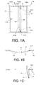
- the following is a description of the door opening/closing device according to an embodiment of the present invention applied to a double-folding door that opens and closes the opening of a toilet unit in an aircraft.
- a door 14 that opens and closes a doorway 12 of a toilet unit 10 is a double-folding door that includes a first door panel 16 and a second door panel 18, and, in the embodiment, the opening is the doorway 12.
- a first end in the width direction of the first door panel 16 is configured so that a guide shaft 1602 provided in the top end of the first door panel 16 moves in the width direction of the doorway 12 by sliding along a guide rail provided in the top edge portion of an installation frame 20.
- top and bottom portions of a second end in the width direction of the first door panel 16 are foldably connected to a first end in the width direction of the second door panel 18 via a door opening/closing device 22.
- a handle 1610 is provided in the first door panel 16.
- a second end in the width direction of the second door panel 18 is rotatably connected to the top edge portion and the bottom edge portion of the installation frame 20 via a rotational shaft 1802.
- the first door panel 16 and the second door panel 18 are curved convex to the outside of the toilet panel, configured so that, in the unfolded state, the first door panel 16 and the second door panel 18 close the doorway 12, and, in the folded state, the first door panel 16 and the second door panel 18 open the doorway 12.
- a first hinge piece 24 is fitted to the second end in the width direction of the first door panel 16, and a second hinge piece 26 is fitted to the first end in the width direction of the second door panel 18. Therefore, the first door panel 16 is configured to include the first hinge piece 24, and the second door panel 18 is configured to include the second hinge piece 26. Also, convex portions 2402 on the top and bottom ends of the first hinge piece 24 are aligned with the top and bottom of a convex portion 2602 of the second hinge piece 26, and are foldably connected by the door opening/closing device 22.
- the door opening/closing device 22 that connects the convex portion 2402 of the top end of the first hinge piece 24 and the top portion of the convex portion 2602 of the second hinge piece 26 has the same configuration as the door opening/closing device 22 that connects the convex portion 2402 at the bottom end of the first hinge piece 24 and the bottom portion of the convex portion 2602 of the second hinge piece 26, so the description is provided taking as an example the door opening/closing device 22 that connects the convex portion 2402 of the top end of the first hinge piece 24 and the top portion of the convex portion 2602 of the second hinge piece 26.
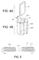
- the door opening/closing device 22 includes a shaft member 30, a torsion spring 32, an outside cylindrical member 34, an inside cylindrical member 36, and a bush 38.
- the shaft member 30 is configured to include a first shaft 40, a second shaft 42, and an attaching member 44.
- the first shaft 40 includes a shaft portion 4002, a fan-shaped shaft member side stopper 4004 provided on the top end of the shaft portion 4002, and a groove 4006 provided in the bottom end of the shaft portion 4002.
- An installation piece 46 is connected to the top end of the shaft portion 4002 via a screw 4602 so that it can rotate integrally with the first shaft 40.
- the installation piece 46 is fitted to the top end surface of the first hinge piece 24 with a screw that is not illustrated in the drawings, and therefore, the top end of the first shaft 40 is fitted so that it cannot rotate to the top end surface of the first hinge piece 24, in other words, to the first door panel 16 side.
- the second shaft 42 includes a shaft portion 4202, a small diameter portion 4204 provided on the bottom end of the shaft portion 4202, and a groove 4206 provided in the top end of the shaft portion 4202.
- the small diameter portion 4204 is rotatably supported on the second door panel 18 side as described later.
- the attaching member 44 includes a cylindrical member 48 and a latch plate 50.
- the cylindrical member 48 includes a cylindrical shaped main body portion 4802, a pair of fitting grooves 4806 formed in locations opposite each other on the inner circumferential surface of a central hole 4804 in the main body portion 4802, and a groove-shaped latching portion 4808 that extends in the axial direction, formed on the outer cylindrical surface of the main body portion 4802.
- the latch plate 50 is inserted into the pair of fitting grooves 4806.
- the bottom end of the first shaft 40 is inserted into the central hole 4804 of the cylindrical member 48 from above, and by fitting the top half of the latch plate 50 into the groove 4006, the first shaft 40 and the attaching member 44 are connected so that they rotate integrally.
- the second shaft 42 and the attaching member 44 are connected so that they rotate integrally.
- first shaft 40 and the second shaft 42 are connected via the attaching member 44 so that they rotate integrally about the same axis.
- the torsion spring 32 is fitted to the shaft member 30 configured in this way.
- the torsion spring 32 is formed from a single wire member, and includes a first coil portion 3202, a second coil portion 3204, and a latched member 3206.
- the first coil portion 3202 and the second coil portion 3204 have the same internal diameter, the same external diameter, have the same number of turns, and are formed coaxially, but their orientations of winding the wire member are opposite to each other.
- the latched member 3206 extends in a linear manner between the first coil portion 3202 and the second coil portion 3204, thereby connecting these coil portions 3202, 3204.
- a first coil portion latching end 32A projects from an end portion of the first coil portion 3202, and a second coil portion latching end 32B projects from an end portion of the second coil portion 3204.
- the first coil portion 3202 is wound around the first shaft 40, and the second coil portion 3204 is wound around the second shaft 42, and the latched member 3206 is latched to the latching portion 4808.
- the shaft member 30 and the torsion spring 32 are disposed on the first door panel 16 and the second door panel 18 using the outside cylindrical member 34 and the inside cylindrical member 36.
- the outside cylindrical member 34 includes a small diameter portion 3402 and a large diameter portion 3404, with a housing hole 3406 with a uniform inside diameter formed in the centers thereof.
- a torsion spring latching wall 3408 projects from the end on the small diameter portion 3402 side inside the housing hole 3406.
- an insertion hole 3410 that links to the housing hole 3406 is opened in the end portion of the small diameter portion 3402, and a cylindrical shaped member side stopper wall 3412 projects from the periphery of the insertion hole 3410.
- a plurality of mating grooves 3414 that extend in the axial direction spaced in the circumferential direction, and, a counterbore 3416 that accommodates the head of a screw 3415 are formed in the large diameter portion 3404, and an opening 3420 of the housing hole 3406 is located on the end portion of the large diameter portion 3404.
- the inside cylindrical member 36 is inserted into the housing hole 3406 from the opening 3420 of the large diameter portion 3404 of the outside cylindrical member 34, and is fixed to the outside cylindrical member 34 so that it cannot rotate by the screw 3415 as described later.
- a support hole 3602 that rotatably supports the small diameter portion 4204 of the second shaft 42 is formed in a first end of the inside cylindrical member 36, and a torsion spring latching wall 3604 projects from the periphery of the support hole 3602.
- a groove 3606 is formed in a second end of the inside cylindrical member 36.
- a screw hole 3608 into which the screw 3415 is screwed is formed in the inside cylindrical member 36.
- the shaft member 30 and the torsion spring 32 are arranged on the first door panel 16 and the second door panel 18 as follows.
- the first shaft 40 is inserted from the groove 4006 into the housing hole 3406 from the insertion hole 3410 at the first end of the outside cylindrical member 34.
- the attaching member 44 is assembled onto the torsion spring 32 latching the latched member 3206 to the latching portion 4808, the second shaft 42 is inserted into the second coil portion 3204 from the groove 4206, the tip of the second shaft 42 is inserted into the central hole 4804 of the cylindrical member 48, and the groove 4206 is latched to the latch plate 50.
- the torsion spring 32 and the second shaft 42 are inserted into the housing hole 3406 from the opening 3420 of the outside cylindrical member 34, and, in this way, the first shaft 40 is inserted into the first coil portion 3202, and the tip of the first shaft 40 is inserted into the central hole 4804 of the cylindrical member 48, and the groove 4006 is latched with the latch plate 50.
- the inside cylindrical member 36 is inserted into the opening 3420 of the outside cylindrical member 34, and the outside cylindrical member 34 and the inside cylindrical member 36 are connected so that they rotate integrally using the screw 3415.
- the first coil portion latching end 32A of the end portion of the first coil portion 3202 is latched to the torsion spring latching wall 3408 on the inside of the outside cylindrical member 34
- the second coil portion latching end 32B of the end portion of the second coil portion 3204 is latched to the torsion spring latching wall 3604 of the inside cylindrical member 36 inside the outside cylindrical member 34.
- the shaft member side stopper 4004 is disposed so that it can contact the cylindrical member side stopper wall 3412 of the end portion of the outside cylindrical member 34, so when the first door panel 16 and the second door panel 18 are in the fully closed state, the shaft member side stopper 4004 contacts a first end in the circumferential direction of the cylindrical member side stopper wall 3412, and, when the first door panel 16 and the second door panel 18 are in the fully open state, the shaft member side stopper 4004 contacts a second end in the circumferential direction of the cylindrical member side stopper wall 3412, thereby restricting the fully closed state and the fully open state.
- the small diameter portion 3402 of the outside cylindrical member 34 into which the shaft member 30, the torsion spring 32, and the inside cylindrical member 36 are assembled is fitted to an installation hole 2422 of the first hinge piece 24, and is rotatably connected to the inner circumferential surface of the bush 38 as illustrated in FIGS. 2 and 8 .
- the installation piece 46 that is exposed from the outside cylindrical member 34 is fitted to the first hinge piece 24 by a screw that is not illustrated in the drawings.
- the large diameter portion 3404 is inserted into an installation hole 2622 of the second hinge piece 26, and by engaging a protrusion that is not illustrated in the drawings provided on the installation hole 2622 with the mating grooves 3414, the large diameter portion 3404 is fitted to the second hinge piece 26 so that it cannot rotate.
- the installation piece 46 is fitted to the first hinge piece 24 by a screw that is not illustrated in the drawings, and the large diameter portion 3404 is fitted to the second hinge piece 26 so that it cannot rotate, the shaft member 30 is rotated a predetermined number of times with respect to the outside cylindrical member 34, and with the first door panel 16 and the second door panel 18 closing the doorway, the first coil portion 3202 and the second coil portion 3204 are each adjusted in the direction to close the doorway 12 by the elastic force tending to restore the first coil portion 3202 and the second coil portion 3204 in the wind open direction.
- the upper half of the outside cylindrical member 34 is rotatably supported on the first door panel 16 side via the bush 38, and the lower half is supported so that it cannot rotate on the second door panel 18 side, so in the embodiment, the outside cylindrical member 34 is configured as a support shaft that foldably connects the first door panel 16 and the second door panel 18.
- the torsion spring 32 is disposed coaxially with the support shaft via the shaft member 30 inside the outside cylindrical member 34.
- the first door panel 16 and the second door panel 18 are impelled in the direction to close the doorway 12 by the elastic force tending to wind open the first coil portion 3202 and the second coil portion 3204.
- the door opening/closing device 22 that connects the convex portion 2402 at the bottom end of the first hinge piece 24 and the bottom portion of the convex portion 2602 of the second hinge piece 26 is configured in the same way but just the vertical orientation is reversed from the embodiment as described above.
- the shaft member 30 is installed on the first door panel 16 side so that it cannot rotate, and the end portions at both ends of the torsion spring 32 are latched to the second door panel 18 side via the torsion spring latching walls 3408, 3604 respectively, and the center portion of the torsion spring 32 is latched to the first door panel 16 side via the latched member 3206, the latching portion 4808, and the shaft member 30.
- both ends of the torsion spring 32 are latched to the second door panel 18 side, and the center portion of the torsion spring 32 is latched to the first door panel 16 side.
- the first door panel 16 and the second door panel 18 move in the direction to close the doorway 12 as a result of the elastic force tending to restore the first coil portion 3202 and the second coil portion 3204 in the direction that they are each wound open, so the doorway 12 is closed by the first door panel 16 and the second door panel 18. Also, this closed state is maintained by the elastic force that tends to restore the first coil portion 3202 and the second coil portion 3204 to the wound open direction.
- the first coil portion 3202 and the second coil portion 3204 deform in the wound closed direction, and this is preferable in terms of durability of the torsion spring 32, and therefore the durability of the torsion spring 32 is increased which has the advantage that the durability of the door opening/closing device 22 is increased.
- the shaft member 30 is provided that includes the first shaft 40 around which the first coil portion 3202 is wound, the second shaft 42 around which the second coil portion 3204 is wound, and the attaching member 44 to which the latched member 3206 that removably connects these is latched, so fixing the torsion spring 32 to the first door panel 16 and the second door panel 18 is simple, which has the advantage that the assembly work efficiency is increased.
- the outside cylindrical member 34 is provided that is configured as a rotational support shaft of the first door panel 16 and the second door panel 18 that covers a portion of the shaft member 30 around which the torsion spring 32 is wound, so this is advantageous in terms of simply and reliably disposing the torsion spring 32 coaxially with the support shaft for rotation of the first and second door panels 16, 18, and, the torsion spring 32 is protected by the outside cylindrical member 34, which is advantageous in terms of further increasing the durability of the torsion spring 32.
- the rotational support shaft that rotatably connects the first door panel 16 and the second door panel 18 may be disposed in a different position from the position in which the shaft member 30 and the torsion spring 32 are disposed, but as in the embodiment, when the outside cylindrical member 34 that protects the torsion spring 32 is used as the rotational support shaft, the number of components is reduced which is advantageous in terms of reducing the size of the door opening/closing device 22.
- the opening in the present invention is a broad concept that includes not only the doorway 12, but also includes the opening of a closet or storage shelves, and the embodiment can be applied to a wide range of door opening/closing devices that open and close an opening with double folding doors.
Landscapes
- Engineering & Computer Science (AREA)
- Mechanical Engineering (AREA)
- Civil Engineering (AREA)
- Structural Engineering (AREA)
- Closing And Opening Devices For Wings, And Checks For Wings (AREA)
- Extensible Doors And Revolving Doors (AREA)
Applications Claiming Priority (2)
| Application Number | Priority Date | Filing Date | Title |
|---|---|---|---|
| JP2012096361A JP5949084B2 (ja) | 2012-04-20 | 2012-04-20 | 扉開閉装置 |
| PCT/JP2013/002639 WO2013157273A1 (ja) | 2012-04-20 | 2013-04-18 | 扉開閉装置 |
Publications (3)
| Publication Number | Publication Date |
|---|---|
| EP2840211A1 true EP2840211A1 (de) | 2015-02-25 |
| EP2840211A4 EP2840211A4 (de) | 2016-04-27 |
| EP2840211B1 EP2840211B1 (de) | 2017-10-18 |
Family
ID=49383243
Family Applications (1)
| Application Number | Title | Priority Date | Filing Date |
|---|---|---|---|
| EP13777829.6A Active EP2840211B1 (de) | 2012-04-20 | 2013-04-18 | Türöffnungs- und schliessvorrichtung |
Country Status (4)
| Country | Link |
|---|---|
| US (1) | US9631410B2 (de) |
| EP (1) | EP2840211B1 (de) |
| JP (1) | JP5949084B2 (de) |
| WO (1) | WO2013157273A1 (de) |
Cited By (1)
| Publication number | Priority date | Publication date | Assignee | Title |
|---|---|---|---|---|
| DE202016001398U1 (de) | 2016-03-04 | 2016-03-24 | Siegenia-Aubi Kg | Fenster oder Tür |
Families Citing this family (12)
| Publication number | Priority date | Publication date | Assignee | Title |
|---|---|---|---|---|
| CH708972B1 (de) * | 2013-12-09 | 2025-11-14 | Jos Berchtold Ag | Falttüre zur Verwendung als Brandschutztüre |
| US10315707B2 (en) * | 2017-07-27 | 2019-06-11 | Cnh Industrial America Llc | Engine hood mounting system |
| JP6544460B1 (ja) | 2018-04-13 | 2019-07-17 | 横浜ゴム株式会社 | 航空機用化粧室ユニットの出入口開閉用扉を構成する2枚の扉体の結合構造 |
| JP6758785B2 (ja) * | 2018-04-25 | 2020-09-23 | スガツネ工業株式会社 | ヒンジ装置 |
| KR101938814B1 (ko) | 2018-06-26 | 2019-01-15 | 재단법인 중소조선연구원 | 자동 개폐 채수기 |
| JP7401783B2 (ja) | 2018-11-05 | 2023-12-20 | 横浜ゴム株式会社 | 航空機用化粧室ユニットの化粧室の扉体の結合構造 |
| KR101992670B1 (ko) * | 2018-12-26 | 2019-06-25 | 이기현 | 폴딩도어 회전장치 |
| GB2585942B (en) * | 2019-07-26 | 2021-10-27 | Kingsway Enterprises Uk Ltd | Door leaf |
| CN117642302A (zh) * | 2021-07-05 | 2024-03-01 | 软车股份公司 | 车门 |
| US20250033774A1 (en) | 2021-12-02 | 2025-01-30 | The Yokohama Rubber Co., Ltd. | Door opening and closing mechanism of aircraft lavatory unit |
| JP7230999B1 (ja) | 2021-12-02 | 2023-03-01 | 横浜ゴム株式会社 | 航空機用化粧室ユニットの扉開閉機構 |
| JP7231000B1 (ja) | 2021-12-02 | 2023-03-01 | 横浜ゴム株式会社 | 航空機用化粧室ユニットの扉開閉機構 |
Family Cites Families (18)
| Publication number | Priority date | Publication date | Assignee | Title |
|---|---|---|---|---|
| US721A (en) * | 1838-04-28 | Hinge fo-r | ||
| US253851A (en) * | 1882-02-21 | Door-spring | ||
| FR469612A (fr) | 1914-03-13 | 1914-08-05 | Emilio Graf | Charnière à ressort |
| US1408583A (en) * | 1921-03-21 | 1922-03-07 | Patrick J Glancey | Screen-door hinge |
| US1487233A (en) * | 1923-04-02 | 1924-03-18 | Glancey Patrick Joseph | Screen-door hinge |
| US1539921A (en) * | 1924-06-11 | 1925-06-02 | Tharp Lee | Automobile door spring |
| US2150435A (en) * | 1938-02-25 | 1939-03-14 | Alvin H Floreth | Door closer and mount |
| GB1514917A (en) * | 1975-02-01 | 1978-06-21 | Crompton Nettlefold Stenman | Door closure units |
| US4649597A (en) * | 1986-01-10 | 1987-03-17 | Cacicedo Paulino A | Automatic gate closure apparatus |
| JPH01142021A (ja) | 1987-11-27 | 1989-06-02 | Sumitomo Metal Ind Ltd | 継目無金属ベルトの製造方法 |
| JPH057624Y2 (de) * | 1988-03-22 | 1993-02-25 | ||
| US5191678A (en) * | 1989-10-30 | 1993-03-09 | T.J. Firari Enterprises | Wind resistant door hardware |
| KR20030074566A (ko) * | 2003-08-29 | 2003-09-19 | 주식회사소진 | 캠을 이용한 도어의 자동폐쇄장치 |
| CN102159787B (zh) * | 2008-09-15 | 2014-07-30 | Sca卫生用品公司 | 铰链装置 |
| JP5487745B2 (ja) * | 2009-06-12 | 2014-05-07 | 横浜ゴム株式会社 | 扉開閉装置 |
| JP5248554B2 (ja) * | 2010-07-01 | 2013-07-31 | 株式会社栃木屋 | 蝶番 |
| US8424160B2 (en) * | 2010-08-11 | 2013-04-23 | E-Lead Electronics Co., Ltd. | Asymmetrical resistant hinge set |
| DE102011007400A1 (de) * | 2011-04-14 | 2012-10-18 | Suspa Gmbh | Schließ-Scharnier |
-
2012
- 2012-04-20 JP JP2012096361A patent/JP5949084B2/ja active Active
-
2013
- 2013-04-18 US US14/395,814 patent/US9631410B2/en active Active
- 2013-04-18 WO PCT/JP2013/002639 patent/WO2013157273A1/ja not_active Ceased
- 2013-04-18 EP EP13777829.6A patent/EP2840211B1/de active Active
Cited By (2)
| Publication number | Priority date | Publication date | Assignee | Title |
|---|---|---|---|---|
| DE202016001398U1 (de) | 2016-03-04 | 2016-03-24 | Siegenia-Aubi Kg | Fenster oder Tür |
| WO2017148663A1 (de) | 2016-03-04 | 2017-09-08 | Siegenia-Aubi Kg | Fenster oder tür |
Also Published As
| Publication number | Publication date |
|---|---|
| JP5949084B2 (ja) | 2016-07-06 |
| WO2013157273A1 (ja) | 2013-10-24 |
| EP2840211A4 (de) | 2016-04-27 |
| US20150096145A1 (en) | 2015-04-09 |
| EP2840211B1 (de) | 2017-10-18 |
| JP2013224525A (ja) | 2013-10-31 |
| US9631410B2 (en) | 2017-04-25 |
Similar Documents
| Publication | Publication Date | Title |
|---|---|---|
| EP2840211B1 (de) | Türöffnungs- und schliessvorrichtung | |
| US8584402B2 (en) | Door opening/closing system and catch therefor | |
| US9765559B2 (en) | Multi-directional rotational sliding door self-closing device | |
| US7003851B2 (en) | Hinge | |
| CN111379507B (zh) | 折叠门旋转装置 | |
| US8327505B2 (en) | Adjustable door stop system | |
| US8646154B2 (en) | Adjustable door stop system | |
| JP2009270262A (ja) | 蝶番装置 | |
| US7194785B2 (en) | Buffer bar fastening structure | |
| US20210230916A1 (en) | Concealed hinge with v-shaped rotating shafts | |
| KR102199994B1 (ko) | 차량용 충전 포트 커버의 슬라이드 가이드 구조 | |
| EP1847671A1 (de) | Vorrichtung zum öffnen und schliessen einer tür | |
| CN209761115U (zh) | 一种铰链及消毒柜 | |
| KR20230032504A (ko) | 도어용 손끼임방지 경첩 | |
| CN210063831U (zh) | 铰接机构和收纳盒 | |
| RU2443839C2 (ru) | Поворотная опора для прижимного механизма закрывающего устройства | |
| CN211369932U (zh) | 一种具有角度限定功能的铰链装置 | |
| CN211818833U (zh) | 一种阻尼式旋转铰链 | |
| KR0118517Y1 (ko) | 양변기의 변기뚜껑이나 변기시트 등의 개폐장치 | |
| KR100889826B1 (ko) | 안전문 | |
| CN101424147A (zh) | 门铰 | |
| KR20170106728A (ko) | 중장비용 스토퍼 힌지 | |
| CN223739206U (zh) | 阻尼铰链 | |
| CN223135897U (zh) | 一种可以定位的铰链 | |
| RU2278936C2 (ru) | Дверная петля |
Legal Events
| Date | Code | Title | Description |
|---|---|---|---|
| PUAI | Public reference made under article 153(3) epc to a published international application that has entered the european phase |
Free format text: ORIGINAL CODE: 0009012 |
|
| 17P | Request for examination filed |
Effective date: 20141020 |
|
| AK | Designated contracting states |
Kind code of ref document: A1 Designated state(s): AL AT BE BG CH CY CZ DE DK EE ES FI FR GB GR HR HU IE IS IT LI LT LU LV MC MK MT NL NO PL PT RO RS SE SI SK SM TR |
|
| AX | Request for extension of the european patent |
Extension state: BA ME |
|
| DAX | Request for extension of the european patent (deleted) | ||
| RIC1 | Information provided on ipc code assigned before grant |
Ipc: E05F 1/14 20060101ALN20160317BHEP Ipc: E05D 5/10 20060101ALI20160317BHEP Ipc: E05D 7/081 20060101ALI20160317BHEP Ipc: E06B 3/48 20060101ALI20160317BHEP Ipc: E05F 1/12 20060101AFI20160317BHEP Ipc: E05D 15/26 20060101ALN20160317BHEP |
|
| RA4 | Supplementary search report drawn up and despatched (corrected) |
Effective date: 20160324 |
|
| REG | Reference to a national code |
Ref country code: DE Ref legal event code: R079 Ref document number: 602013028157 Country of ref document: DE Free format text: PREVIOUS MAIN CLASS: E05F0001140000 Ipc: E05F0001120000 |
|
| RIC1 | Information provided on ipc code assigned before grant |
Ipc: E05F 1/14 20060101ALN20170310BHEP Ipc: E05F 1/12 20060101AFI20170310BHEP Ipc: E05D 5/10 20060101ALI20170310BHEP Ipc: E05D 15/26 20060101ALN20170310BHEP Ipc: E06B 3/48 20060101ALI20170310BHEP Ipc: E05D 7/081 20060101ALI20170310BHEP |
|
| GRAP | Despatch of communication of intention to grant a patent |
Free format text: ORIGINAL CODE: EPIDOSNIGR1 |
|
| STAA | Information on the status of an ep patent application or granted ep patent |
Free format text: STATUS: GRANT OF PATENT IS INTENDED |
|
| INTG | Intention to grant announced |
Effective date: 20170425 |
|
| GRAS | Grant fee paid |
Free format text: ORIGINAL CODE: EPIDOSNIGR3 |
|
| GRAA | (expected) grant |
Free format text: ORIGINAL CODE: 0009210 |
|
| STAA | Information on the status of an ep patent application or granted ep patent |
Free format text: STATUS: THE PATENT HAS BEEN GRANTED |
|
| AK | Designated contracting states |
Kind code of ref document: B1 Designated state(s): AL AT BE BG CH CY CZ DE DK EE ES FI FR GB GR HR HU IE IS IT LI LT LU LV MC MK MT NL NO PL PT RO RS SE SI SK SM TR |
|
| REG | Reference to a national code |
Ref country code: GB Ref legal event code: FG4D |
|
| REG | Reference to a national code |
Ref country code: CH Ref legal event code: EP |
|
| REG | Reference to a national code |
Ref country code: AT Ref legal event code: REF Ref document number: 938108 Country of ref document: AT Kind code of ref document: T Effective date: 20171115 Ref country code: IE Ref legal event code: FG4D |
|
| REG | Reference to a national code |
Ref country code: DE Ref legal event code: R096 Ref document number: 602013028157 Country of ref document: DE |
|
| REG | Reference to a national code |
Ref country code: NL Ref legal event code: MP Effective date: 20171018 |
|
| REG | Reference to a national code |
Ref country code: LT Ref legal event code: MG4D |
|
| REG | Reference to a national code |
Ref country code: AT Ref legal event code: MK05 Ref document number: 938108 Country of ref document: AT Kind code of ref document: T Effective date: 20171018 Ref country code: FR Ref legal event code: PLFP Year of fee payment: 6 |
|
| PG25 | Lapsed in a contracting state [announced via postgrant information from national office to epo] |
Ref country code: NL Free format text: LAPSE BECAUSE OF FAILURE TO SUBMIT A TRANSLATION OF THE DESCRIPTION OR TO PAY THE FEE WITHIN THE PRESCRIBED TIME-LIMIT Effective date: 20171018 |
|
| PG25 | Lapsed in a contracting state [announced via postgrant information from national office to epo] |
Ref country code: NO Free format text: LAPSE BECAUSE OF FAILURE TO SUBMIT A TRANSLATION OF THE DESCRIPTION OR TO PAY THE FEE WITHIN THE PRESCRIBED TIME-LIMIT Effective date: 20180118 Ref country code: LT Free format text: LAPSE BECAUSE OF FAILURE TO SUBMIT A TRANSLATION OF THE DESCRIPTION OR TO PAY THE FEE WITHIN THE PRESCRIBED TIME-LIMIT Effective date: 20171018 Ref country code: ES Free format text: LAPSE BECAUSE OF FAILURE TO SUBMIT A TRANSLATION OF THE DESCRIPTION OR TO PAY THE FEE WITHIN THE PRESCRIBED TIME-LIMIT Effective date: 20171018 Ref country code: FI Free format text: LAPSE BECAUSE OF FAILURE TO SUBMIT A TRANSLATION OF THE DESCRIPTION OR TO PAY THE FEE WITHIN THE PRESCRIBED TIME-LIMIT Effective date: 20171018 Ref country code: SE Free format text: LAPSE BECAUSE OF FAILURE TO SUBMIT A TRANSLATION OF THE DESCRIPTION OR TO PAY THE FEE WITHIN THE PRESCRIBED TIME-LIMIT Effective date: 20171018 |
|
| PG25 | Lapsed in a contracting state [announced via postgrant information from national office to epo] |
Ref country code: AT Free format text: LAPSE BECAUSE OF FAILURE TO SUBMIT A TRANSLATION OF THE DESCRIPTION OR TO PAY THE FEE WITHIN THE PRESCRIBED TIME-LIMIT Effective date: 20171018 Ref country code: BG Free format text: LAPSE BECAUSE OF FAILURE TO SUBMIT A TRANSLATION OF THE DESCRIPTION OR TO PAY THE FEE WITHIN THE PRESCRIBED TIME-LIMIT Effective date: 20180118 Ref country code: RS Free format text: LAPSE BECAUSE OF FAILURE TO SUBMIT A TRANSLATION OF THE DESCRIPTION OR TO PAY THE FEE WITHIN THE PRESCRIBED TIME-LIMIT Effective date: 20171018 Ref country code: GR Free format text: LAPSE BECAUSE OF FAILURE TO SUBMIT A TRANSLATION OF THE DESCRIPTION OR TO PAY THE FEE WITHIN THE PRESCRIBED TIME-LIMIT Effective date: 20180119 Ref country code: LV Free format text: LAPSE BECAUSE OF FAILURE TO SUBMIT A TRANSLATION OF THE DESCRIPTION OR TO PAY THE FEE WITHIN THE PRESCRIBED TIME-LIMIT Effective date: 20171018 Ref country code: HR Free format text: LAPSE BECAUSE OF FAILURE TO SUBMIT A TRANSLATION OF THE DESCRIPTION OR TO PAY THE FEE WITHIN THE PRESCRIBED TIME-LIMIT Effective date: 20171018 Ref country code: IS Free format text: LAPSE BECAUSE OF FAILURE TO SUBMIT A TRANSLATION OF THE DESCRIPTION OR TO PAY THE FEE WITHIN THE PRESCRIBED TIME-LIMIT Effective date: 20180218 |
|
| REG | Reference to a national code |
Ref country code: DE Ref legal event code: R097 Ref document number: 602013028157 Country of ref document: DE |
|
| PG25 | Lapsed in a contracting state [announced via postgrant information from national office to epo] |
Ref country code: CZ Free format text: LAPSE BECAUSE OF FAILURE TO SUBMIT A TRANSLATION OF THE DESCRIPTION OR TO PAY THE FEE WITHIN THE PRESCRIBED TIME-LIMIT Effective date: 20171018 Ref country code: DK Free format text: LAPSE BECAUSE OF FAILURE TO SUBMIT A TRANSLATION OF THE DESCRIPTION OR TO PAY THE FEE WITHIN THE PRESCRIBED TIME-LIMIT Effective date: 20171018 Ref country code: EE Free format text: LAPSE BECAUSE OF FAILURE TO SUBMIT A TRANSLATION OF THE DESCRIPTION OR TO PAY THE FEE WITHIN THE PRESCRIBED TIME-LIMIT Effective date: 20171018 Ref country code: SK Free format text: LAPSE BECAUSE OF FAILURE TO SUBMIT A TRANSLATION OF THE DESCRIPTION OR TO PAY THE FEE WITHIN THE PRESCRIBED TIME-LIMIT Effective date: 20171018 |
|
| PLBE | No opposition filed within time limit |
Free format text: ORIGINAL CODE: 0009261 |
|
| STAA | Information on the status of an ep patent application or granted ep patent |
Free format text: STATUS: NO OPPOSITION FILED WITHIN TIME LIMIT |
|
| PG25 | Lapsed in a contracting state [announced via postgrant information from national office to epo] |
Ref country code: RO Free format text: LAPSE BECAUSE OF FAILURE TO SUBMIT A TRANSLATION OF THE DESCRIPTION OR TO PAY THE FEE WITHIN THE PRESCRIBED TIME-LIMIT Effective date: 20171018 Ref country code: IT Free format text: LAPSE BECAUSE OF FAILURE TO SUBMIT A TRANSLATION OF THE DESCRIPTION OR TO PAY THE FEE WITHIN THE PRESCRIBED TIME-LIMIT Effective date: 20171018 Ref country code: SM Free format text: LAPSE BECAUSE OF FAILURE TO SUBMIT A TRANSLATION OF THE DESCRIPTION OR TO PAY THE FEE WITHIN THE PRESCRIBED TIME-LIMIT Effective date: 20171018 Ref country code: PL Free format text: LAPSE BECAUSE OF FAILURE TO SUBMIT A TRANSLATION OF THE DESCRIPTION OR TO PAY THE FEE WITHIN THE PRESCRIBED TIME-LIMIT Effective date: 20171018 |
|
| 26N | No opposition filed |
Effective date: 20180719 |
|
| PG25 | Lapsed in a contracting state [announced via postgrant information from national office to epo] |
Ref country code: MC Free format text: LAPSE BECAUSE OF FAILURE TO SUBMIT A TRANSLATION OF THE DESCRIPTION OR TO PAY THE FEE WITHIN THE PRESCRIBED TIME-LIMIT Effective date: 20171018 Ref country code: SI Free format text: LAPSE BECAUSE OF FAILURE TO SUBMIT A TRANSLATION OF THE DESCRIPTION OR TO PAY THE FEE WITHIN THE PRESCRIBED TIME-LIMIT Effective date: 20171018 |
|
| REG | Reference to a national code |
Ref country code: CH Ref legal event code: PL |
|
| REG | Reference to a national code |
Ref country code: BE Ref legal event code: MM Effective date: 20180430 |
|
| GBPC | Gb: european patent ceased through non-payment of renewal fee |
Effective date: 20180418 |
|
| REG | Reference to a national code |
Ref country code: IE Ref legal event code: MM4A |
|
| PG25 | Lapsed in a contracting state [announced via postgrant information from national office to epo] |
Ref country code: LU Free format text: LAPSE BECAUSE OF NON-PAYMENT OF DUE FEES Effective date: 20180418 |
|
| PG25 | Lapsed in a contracting state [announced via postgrant information from national office to epo] |
Ref country code: CH Free format text: LAPSE BECAUSE OF NON-PAYMENT OF DUE FEES Effective date: 20180430 Ref country code: GB Free format text: LAPSE BECAUSE OF NON-PAYMENT OF DUE FEES Effective date: 20180418 Ref country code: LI Free format text: LAPSE BECAUSE OF NON-PAYMENT OF DUE FEES Effective date: 20180430 Ref country code: BE Free format text: LAPSE BECAUSE OF NON-PAYMENT OF DUE FEES Effective date: 20180430 |
|
| PG25 | Lapsed in a contracting state [announced via postgrant information from national office to epo] |
Ref country code: IE Free format text: LAPSE BECAUSE OF NON-PAYMENT OF DUE FEES Effective date: 20180418 |
|
| PG25 | Lapsed in a contracting state [announced via postgrant information from national office to epo] |
Ref country code: MT Free format text: LAPSE BECAUSE OF NON-PAYMENT OF DUE FEES Effective date: 20180418 |
|
| PG25 | Lapsed in a contracting state [announced via postgrant information from national office to epo] |
Ref country code: TR Free format text: LAPSE BECAUSE OF FAILURE TO SUBMIT A TRANSLATION OF THE DESCRIPTION OR TO PAY THE FEE WITHIN THE PRESCRIBED TIME-LIMIT Effective date: 20171018 |
|
| PG25 | Lapsed in a contracting state [announced via postgrant information from national office to epo] |
Ref country code: PT Free format text: LAPSE BECAUSE OF FAILURE TO SUBMIT A TRANSLATION OF THE DESCRIPTION OR TO PAY THE FEE WITHIN THE PRESCRIBED TIME-LIMIT Effective date: 20171018 Ref country code: HU Free format text: LAPSE BECAUSE OF FAILURE TO SUBMIT A TRANSLATION OF THE DESCRIPTION OR TO PAY THE FEE WITHIN THE PRESCRIBED TIME-LIMIT; INVALID AB INITIO Effective date: 20130418 |
|
| PG25 | Lapsed in a contracting state [announced via postgrant information from national office to epo] |
Ref country code: MK Free format text: LAPSE BECAUSE OF NON-PAYMENT OF DUE FEES Effective date: 20171018 Ref country code: CY Free format text: LAPSE BECAUSE OF FAILURE TO SUBMIT A TRANSLATION OF THE DESCRIPTION OR TO PAY THE FEE WITHIN THE PRESCRIBED TIME-LIMIT Effective date: 20171018 |
|
| PG25 | Lapsed in a contracting state [announced via postgrant information from national office to epo] |
Ref country code: AL Free format text: LAPSE BECAUSE OF FAILURE TO SUBMIT A TRANSLATION OF THE DESCRIPTION OR TO PAY THE FEE WITHIN THE PRESCRIBED TIME-LIMIT Effective date: 20171018 |
|
| PGFP | Annual fee paid to national office [announced via postgrant information from national office to epo] |
Ref country code: FR Payment date: 20220308 Year of fee payment: 10 |
|
| P01 | Opt-out of the competence of the unified patent court (upc) registered |
Effective date: 20230512 |
|
| PG25 | Lapsed in a contracting state [announced via postgrant information from national office to epo] |
Ref country code: FR Free format text: LAPSE BECAUSE OF NON-PAYMENT OF DUE FEES Effective date: 20230430 |
|
| PGFP | Annual fee paid to national office [announced via postgrant information from national office to epo] |
Ref country code: DE Payment date: 20250305 Year of fee payment: 13 |