WO2013157273A1 - 扉開閉装置 - Google Patents
扉開閉装置 Download PDFInfo
- Publication number
- WO2013157273A1 WO2013157273A1 PCT/JP2013/002639 JP2013002639W WO2013157273A1 WO 2013157273 A1 WO2013157273 A1 WO 2013157273A1 JP 2013002639 W JP2013002639 W JP 2013002639W WO 2013157273 A1 WO2013157273 A1 WO 2013157273A1
- Authority
- WO
- WIPO (PCT)
- Prior art keywords
- door body
- door
- cylindrical member
- opening
- torsion spring
- Prior art date
Links
- 230000005489 elastic deformation Effects 0.000 abstract 1
- 230000004308 accommodation Effects 0.000 description 7
- 230000002093 peripheral effect Effects 0.000 description 4
- 230000002708 enhancing effect Effects 0.000 description 3
- 230000037431 insertion Effects 0.000 description 3
- 238000003780 insertion Methods 0.000 description 3
- 230000008878 coupling Effects 0.000 description 1
- 238000010168 coupling process Methods 0.000 description 1
- 238000005859 coupling reaction Methods 0.000 description 1
- 230000001105 regulatory effect Effects 0.000 description 1
Images


Classifications
-
- E—FIXED CONSTRUCTIONS
- E05—LOCKS; KEYS; WINDOW OR DOOR FITTINGS; SAFES
- E05F—DEVICES FOR MOVING WINGS INTO OPEN OR CLOSED POSITION; CHECKS FOR WINGS; WING FITTINGS NOT OTHERWISE PROVIDED FOR, CONCERNED WITH THE FUNCTIONING OF THE WING
- E05F1/00—Closers or openers for wings, not otherwise provided for in this subclass
- E05F1/08—Closers or openers for wings, not otherwise provided for in this subclass spring-actuated, e.g. for horizontally sliding wings
- E05F1/10—Closers or openers for wings, not otherwise provided for in this subclass spring-actuated, e.g. for horizontally sliding wings for swinging wings, e.g. counterbalance
- E05F1/1008—Closers or openers for wings, not otherwise provided for in this subclass spring-actuated, e.g. for horizontally sliding wings for swinging wings, e.g. counterbalance with a coil spring parallel with the pivot axis
-
- E—FIXED CONSTRUCTIONS
- E05—LOCKS; KEYS; WINDOW OR DOOR FITTINGS; SAFES
- E05D—HINGES OR SUSPENSION DEVICES FOR DOORS, WINDOWS OR WINGS
- E05D15/00—Suspension arrangements for wings
- E05D15/26—Suspension arrangements for wings for folding wings
- E05D15/264—Suspension arrangements for wings for folding wings for bi-fold wings
- E05D15/266—Suspension arrangements for wings for folding wings for bi-fold wings comprising two pivots placed at opposite edges of the wing
-
- E—FIXED CONSTRUCTIONS
- E05—LOCKS; KEYS; WINDOW OR DOOR FITTINGS; SAFES
- E05D—HINGES OR SUSPENSION DEVICES FOR DOORS, WINDOWS OR WINGS
- E05D5/00—Construction of single parts, e.g. the parts for attachment
- E05D5/10—Pins, sockets or sleeves; Removable pins
-
- E—FIXED CONSTRUCTIONS
- E05—LOCKS; KEYS; WINDOW OR DOOR FITTINGS; SAFES
- E05D—HINGES OR SUSPENSION DEVICES FOR DOORS, WINDOWS OR WINGS
- E05D7/00—Hinges or pivots of special construction
- E05D7/08—Hinges or pivots of special construction for use in suspensions comprising two spigots placed at opposite edges of the wing, especially at the top and the bottom, e.g. trunnions
- E05D7/081—Hinges or pivots of special construction for use in suspensions comprising two spigots placed at opposite edges of the wing, especially at the top and the bottom, e.g. trunnions the pivot axis of the wing being situated near one edge of the wing, especially at the top and bottom, e.g. trunnions
-
- E—FIXED CONSTRUCTIONS
- E05—LOCKS; KEYS; WINDOW OR DOOR FITTINGS; SAFES
- E05F—DEVICES FOR MOVING WINGS INTO OPEN OR CLOSED POSITION; CHECKS FOR WINGS; WING FITTINGS NOT OTHERWISE PROVIDED FOR, CONCERNED WITH THE FUNCTIONING OF THE WING
- E05F1/00—Closers or openers for wings, not otherwise provided for in this subclass
- E05F1/08—Closers or openers for wings, not otherwise provided for in this subclass spring-actuated, e.g. for horizontally sliding wings
- E05F1/10—Closers or openers for wings, not otherwise provided for in this subclass spring-actuated, e.g. for horizontally sliding wings for swinging wings, e.g. counterbalance
- E05F1/12—Mechanisms in the shape of hinges or pivots, operated by springs
- E05F1/1207—Mechanisms in the shape of hinges or pivots, operated by springs with a coil spring parallel with the pivot axis
- E05F1/1215—Mechanisms in the shape of hinges or pivots, operated by springs with a coil spring parallel with the pivot axis with a canted-coil torsion spring
-
- E—FIXED CONSTRUCTIONS
- E06—DOORS, WINDOWS, SHUTTERS, OR ROLLER BLINDS IN GENERAL; LADDERS
- E06B—FIXED OR MOVABLE CLOSURES FOR OPENINGS IN BUILDINGS, VEHICLES, FENCES OR LIKE ENCLOSURES IN GENERAL, e.g. DOORS, WINDOWS, BLINDS, GATES
- E06B3/00—Window sashes, door leaves, or like elements for closing wall or like openings; Layout of fixed or moving closures, e.g. windows in wall or like openings; Features of rigidly-mounted outer frames relating to the mounting of wing frames
- E06B3/32—Arrangements of wings characterised by the manner of movement; Arrangements of movable wings in openings; Features of wings or frames relating solely to the manner of movement of the wing
- E06B3/48—Wings connected at their edges, e.g. foldable wings
- E06B3/481—Wings foldable in a zig-zag manner or bi-fold wings
-
- E—FIXED CONSTRUCTIONS
- E06—DOORS, WINDOWS, SHUTTERS, OR ROLLER BLINDS IN GENERAL; LADDERS
- E06B—FIXED OR MOVABLE CLOSURES FOR OPENINGS IN BUILDINGS, VEHICLES, FENCES OR LIKE ENCLOSURES IN GENERAL, e.g. DOORS, WINDOWS, BLINDS, GATES
- E06B3/00—Window sashes, door leaves, or like elements for closing wall or like openings; Layout of fixed or moving closures, e.g. windows in wall or like openings; Features of rigidly-mounted outer frames relating to the mounting of wing frames
- E06B3/70—Door leaves
- E06B3/7007—Door leaves with curved, e.g. cylindrical or oval cross-section
-
- E—FIXED CONSTRUCTIONS
- E05—LOCKS; KEYS; WINDOW OR DOOR FITTINGS; SAFES
- E05D—HINGES OR SUSPENSION DEVICES FOR DOORS, WINDOWS OR WINGS
- E05D15/00—Suspension arrangements for wings
- E05D15/26—Suspension arrangements for wings for folding wings
-
- E—FIXED CONSTRUCTIONS
- E05—LOCKS; KEYS; WINDOW OR DOOR FITTINGS; SAFES
- E05D—HINGES OR SUSPENSION DEVICES FOR DOORS, WINDOWS OR WINGS
- E05D5/00—Construction of single parts, e.g. the parts for attachment
- E05D5/10—Pins, sockets or sleeves; Removable pins
- E05D2005/102—Pins
-
- E—FIXED CONSTRUCTIONS
- E05—LOCKS; KEYS; WINDOW OR DOOR FITTINGS; SAFES
- E05F—DEVICES FOR MOVING WINGS INTO OPEN OR CLOSED POSITION; CHECKS FOR WINGS; WING FITTINGS NOT OTHERWISE PROVIDED FOR, CONCERNED WITH THE FUNCTIONING OF THE WING
- E05F1/00—Closers or openers for wings, not otherwise provided for in this subclass
- E05F1/08—Closers or openers for wings, not otherwise provided for in this subclass spring-actuated, e.g. for horizontally sliding wings
- E05F1/10—Closers or openers for wings, not otherwise provided for in this subclass spring-actuated, e.g. for horizontally sliding wings for swinging wings, e.g. counterbalance
- E05F1/14—Closers or openers for wings, not otherwise provided for in this subclass spring-actuated, e.g. for horizontally sliding wings for swinging wings, e.g. counterbalance with double-acting springs, e.g. for closing and opening or checking and closing no material
-
- E—FIXED CONSTRUCTIONS
- E05—LOCKS; KEYS; WINDOW OR DOOR FITTINGS; SAFES
- E05Y—INDEXING SCHEME ASSOCIATED WITH SUBCLASSES E05D AND E05F, RELATING TO CONSTRUCTION ELEMENTS, ELECTRIC CONTROL, POWER SUPPLY, POWER SIGNAL OR TRANSMISSION, USER INTERFACES, MOUNTING OR COUPLING, DETAILS, ACCESSORIES, AUXILIARY OPERATIONS NOT OTHERWISE PROVIDED FOR, APPLICATION THEREOF
- E05Y2800/00—Details, accessories and auxiliary operations not otherwise provided for
- E05Y2800/26—Form or shape
- E05Y2800/28—Form or shape tubular, annular
-
- E—FIXED CONSTRUCTIONS
- E05—LOCKS; KEYS; WINDOW OR DOOR FITTINGS; SAFES
- E05Y—INDEXING SCHEME ASSOCIATED WITH SUBCLASSES E05D AND E05F, RELATING TO CONSTRUCTION ELEMENTS, ELECTRIC CONTROL, POWER SUPPLY, POWER SIGNAL OR TRANSMISSION, USER INTERFACES, MOUNTING OR COUPLING, DETAILS, ACCESSORIES, AUXILIARY OPERATIONS NOT OTHERWISE PROVIDED FOR, APPLICATION THEREOF
- E05Y2900/00—Application of doors, windows, wings or fittings thereof
- E05Y2900/10—Application of doors, windows, wings or fittings thereof for buildings or parts thereof
- E05Y2900/112—Application of doors, windows, wings or fittings thereof for buildings or parts thereof for restrooms
-
- E—FIXED CONSTRUCTIONS
- E05—LOCKS; KEYS; WINDOW OR DOOR FITTINGS; SAFES
- E05Y—INDEXING SCHEME ASSOCIATED WITH SUBCLASSES E05D AND E05F, RELATING TO CONSTRUCTION ELEMENTS, ELECTRIC CONTROL, POWER SUPPLY, POWER SIGNAL OR TRANSMISSION, USER INTERFACES, MOUNTING OR COUPLING, DETAILS, ACCESSORIES, AUXILIARY OPERATIONS NOT OTHERWISE PROVIDED FOR, APPLICATION THEREOF
- E05Y2900/00—Application of doors, windows, wings or fittings thereof
- E05Y2900/10—Application of doors, windows, wings or fittings thereof for buildings or parts thereof
- E05Y2900/13—Type of wing
- E05Y2900/132—Doors
Definitions
- the present invention relates to a door opening / closing device, and more particularly to a door opening / closing device that is advantageous in enhancing the durability of a torsion spring used in a door opening / closing device of a two-fold door.
- the door opening and closing device of a double fold door that closes the opening when the two doors are unfolded and opens the opening when the doors are bent is coupled so that the two doors can be bent.
- a torsion spring disposed coaxially with the support shaft. The door body is opened against the elastic force of the torsion spring, and the door body is automatically closed by the elastic force of the torsion spring.
- the conventional door opening and closing device uses a torsion spring having a single coil part, the coil part is wound up when the door is opened and the coil part is closed when the door is closed. You must use a torsion spring to tighten it.
- the present invention has been devised in view of the above circumstances, and an object of the present invention is to provide a door opening / closing device that is advantageous in enhancing the durability of a torsion spring used in the door opening / closing device. .
- the present invention provides a support shaft that foldably connects the first door body and the second door body, and the first door body and the coaxial shaft coaxially with the axis of the support shaft.
- a torsion spring provided over the second door body, the opening is closed in a state where the first door body and the second door body are unfolded, and the door bodies are bent.
- the torsion spring is a two-fold door opening / closing device that urges the first door body and the second door body in a direction to close the opening.
- the torsion spring includes a first coil portion and a second coil portion which are made of a single wire and are coaxially spaced from each other and wound in opposite directions, and the first coil portion, A locked portion that connects the second coil portion, the locked portion being locked to the first door body side, and the locked portion of the first coil portion. An end of the second coil portion opposite to the locked portion is locked to the second door body side, and the first door and the first The door body of 2 is biased in a direction to close the opening by an elastic force to return in a direction in which the first coil portion and the second coil portion are respectively expanded. To do.
- the locked portion is locked to the first door body side, and both ends of the torsion spring are the first door. Since it latches on the 2 door body side and deform
- FIG. 5 is a perspective view in which a torsion spring is attached to a shaft member.
- FIG. 3 is a perspective view of a state in which a torsion spring is mounted on a shaft member, and these are covered with an outer cylindrical member and a bush.
- the door 14 that opens and closes the entrance / exit 12 of the restroom unit 10 is a two-fold door composed of a first door body 16 and a second door body 18.
- the opening is the entrance 12.
- One end of the first door body 16 in the width direction is such that a guide shaft 1602 provided at the upper end of the first door body 16 slides along a guide rail provided at the upper edge of the mounting frame 20. It is configured to move in the width direction of the entrance 12.
- the upper and lower ends of the other end in the width direction of the first door body 16 are foldably coupled to one end in the width direction of the second door body 18 via the door opening and closing device 22.
- the first door body 16 is provided with a handle 1610.
- the other end in the width direction of the second door body 18 is rotatably coupled to the upper edge portion and the lower edge portion of the attachment frame 20 via a rotation shaft 1802.
- the first door body 16 and the second door body 18 have a convex curved shape on the outside of the restroom, and the doorway 12 is in a state where the first door body 16 and the second door body 18 are unfolded.
- the door 12 is configured to be opened in a state where the first door body 16 and the second door body 18 are bent.
- first hinge piece 24 is attached to the other end in the width direction of the first door body 16, and the second hinge piece 26 is attached to one end in the width direction of the second door body 18. It is worn.
- first door body 16 is configured to include the first hinge piece 24, and the second door body 18 is configured to include the second hinge piece 26. Then, the convex portions 2402 at the upper and lower ends of the first hinge piece 24 are respectively aligned with the upper and lower portions of the convex portion 2602 of the second hinge piece 26 and are coupled by the door opening / closing device 22 so as to be bent.
- the door opening / closing device 22 that couples the convex portion 2402 at the upper end of the first hinge piece 24 and the upper portion of the convex portion 2602 of the second hinge piece 26, the convex portion 2402 at the lower end of the first hinge piece 24, and the second Since the door opening and closing device 22 that connects the lower part of the convex part 2602 of the hinge piece 26 has the same configuration, the convex part 2402 at the upper end of the first hinge piece 24 and the convex part 2602 of the second hinge piece 26
- the door opening / closing device 22 that joins the upper portion will be described as an example.
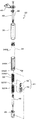
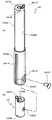
- the door opening / closing device 22 includes a shaft member 30, a torsion spring 32, an outer cylindrical member 34, an inner cylindrical member 36, and a bush 38.
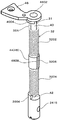
- the shaft member 30 includes a first shaft 40, a second shaft 42, and a connecting member 44.
- the first shaft 40 includes a shaft portion 4002, a fan-shaped shaft member side stopper 4004 provided at the upper end of the shaft portion 4002, and a groove 4006 provided at the lower end of the shaft portion 4002.
- An attachment piece 46 is coupled to the upper end of the shaft portion 4002 via a screw 4602 so as to be integrally rotatable with the first shaft 40.
- the mounting piece 46 is attached to the upper end surface of the first hinge piece 24 with a screw (not shown). Therefore, the upper end of the first shaft 40 is the upper end surface of the first hinge piece 24, that is, the first hinge piece 24.
- the door body 16 is attached so as not to rotate.
- the second shaft 42 includes a shaft portion 4202, a small diameter portion 4204 provided at the lower end of the shaft portion 4202, and a groove 4206 provided at the upper end of the shaft portion 4202.
- this small diameter part 4204 is rotatably supported by the 2nd door body 18 side so that it may mention later.
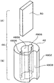
- the connecting member 44 includes a cylindrical member 48 and a locking plate 50.
- the cylindrical member 48 is formed on a cylindrical main body portion 4802, a pair of fitting grooves 4806 formed in mutually opposing locations on the inner peripheral surface of the center hole 4804 of the main body portion 4802, and the outer peripheral surface of the main body portion 4802. And a groove-like locking portion 4808 extending in the axial direction.
- the locking plate 50 is inserted into the pair of fitting grooves 4806.
- the lower end of the first shaft 40 is inserted into the center hole 4804 of the cylindrical member 48 from above, and the upper half of the locking plate 50 is fitted into the groove 4006, so that the first shaft 40, the connecting member 44, Are coupled to rotate together.
- the upper end of the second shaft 42 is inserted into the center hole 4804 of the cylindrical member 48 from below, and the lower half of the locking plate 50 is fitted into the groove 4206, so that the second shaft 42 and the connecting member are inserted. 44 is coupled to rotate integrally. Therefore, the first shaft 40 and the second shaft 42 are coupled via the connecting member 44 so as to rotate integrally on the same axis.
- the torsion spring 32 is attached to the shaft member 30 having such a configuration.
- the torsion spring 32 is formed of a single wire, and includes a first coil portion 3202, a second coil portion 3204, and a locked portion 3206.
- the first coil portion 3202 and the second coil portion 3204 are formed coaxially with the same inner diameter, the same outer diameter, and the same number of turns, and the directions in which the wire is wound are opposite to each other.
- the locked portion 3206 extends linearly between the first coil portion 3202 and the second coil portion 3204 and connects the coil portions 3202 and 3204.
- a first coil portion locking end 32 A protrudes from the end of the first coil portion 3202, and a second coil portion locking end 32 B protrudes from the end of the second coil portion 3204.
- the first coil portion 3202 is wound around the first shaft 40
- the second coil portion 3204 is wound around the second shaft 42
- the locked portion 3206 is the locking portion. 4808.
- the shaft member 30 and the torsion spring 32 are disposed on the first door body 16 and the second door body 18 using the outer cylindrical member 34 and the inner cylindrical member 36.
- the outer cylindrical member 34 has a small diameter portion 3402 and a large diameter portion 3404, and an accommodation hole 3406 having a uniform inner diameter is formed at the center thereof.
- a torsion spring locking wall 3408 projects from the end on the small diameter portion 3402 side.
- an insertion hole 3410 communicating with the accommodation hole 3406 is opened at the end of the small diameter portion 3402, and a cylindrical member side stopper wall 3412 is provided around the insertion hole 3410.
- the large-diameter portion 3404 is formed with a plurality of engaging grooves 3414 extending in the axial direction at intervals in the circumferential direction, and a counterbore 3416 that accommodates the head of the screw 3415 is formed.
- the opening 3420 of the accommodation hole 3406 is located at the end of the first hole.
- the inner cylindrical member 36 is inserted into the accommodation hole 3406 through the opening 3420 of the large-diameter portion 3404 of the outer cylindrical member 34, and the outer cylindrical member 34 is screwed by a screw 3415 as will be described later. It is attached non-rotatably.
- a support hole 3602 that rotatably supports the small-diameter portion 4204 of the second shaft 42 is formed at one end of the inner cylindrical member 36, and a torsion spring locking wall 3604 protrudes around the support hole 3602.
- a groove 3606 is formed at the other end of the inner cylindrical member 36.
- the inner cylindrical member 36 is formed with a screw hole 3608 into which the screw 3415 is screwed.
- the shaft member 30 and the torsion spring 32 are disposed on the first door body 16 and the second door body 18 as follows. As shown in FIGS. 7 and 8, the first shaft 40 is inserted from the groove 4006 into the accommodation hole 3406 through the insertion hole 3410 at one end of the outer cylindrical member 34. Further, the locking portion 4808 is locked to the locked portion 3206, the connecting member 44 is assembled to the torsion spring 32, the second shaft 42 is inserted into the second coil portion 3204 from the groove 4206, and the first The tip of the second shaft 42 is inserted into the center hole 4804 of the cylindrical member 48, and the groove 4206 is locked to the locking plate 50.
- the torsion spring 32 and the second shaft 42 are inserted into the accommodation hole 3406 through the opening 3420 of the outer cylindrical member 34, whereby the first shaft 40 is inserted into the first coil portion 3202, and The tip of one shaft 40 is inserted into the center hole 4804 of the cylindrical member 48, and the groove 4006 is locked to the locking plate 50.
- the inner cylindrical member 36 is inserted into the opening 3420 of the outer cylindrical member 34, and the outer cylindrical member 34 and the inner cylindrical member 36 are coupled together by a screw 3415 so as to be integrally rotatable.
- the first coil portion locking end 32A at the end of the first coil portion 3202 is locked to the torsion spring locking wall 3408 inside the outer cylindrical member 34, and the second coil portion.
- the second coil portion locking end 32 ⁇ / b> B at the end of 3204 is locked to the torsion spring locking wall 3604 of the inner cylindrical member 36 inside the outer cylindrical member 34.
- the shaft member side stopper 4004 is disposed so as to be able to contact the cylindrical member side stopper wall 3412 at the end of the outer cylindrical member 34, and the first door body 16 and the second door body 18 are fully closed.
- the shaft member side stopper 4004 abuts on one end of the cylindrical member side stopper wall 3412 in the circumferential direction, and the shaft member side stopper 4004 is in the fully opened state of the first door body 16 and the second door body 18. Abutting on the other end in the circumferential direction of the cylindrical member side stopper wall 3412, the fully closed state and the fully open state are regulated.
- the outer cylindrical member 34 in which the shaft member 30, the torsion spring 32, and the inner cylindrical member 36 are incorporated has the small diameter portion 3402 fitted in the mounting hole 2422 of the first hinge piece 24. It couple
- the attachment piece 46 exposed from the outer cylindrical member 34 is attached to the first hinge piece 24 with a screw (not shown).
- the large-diameter portion 3404 is inserted into the mounting hole 2622 of the second hinge piece 26, and a convex portion (not shown) provided in the mounting hole 2622 is engaged with the engaging groove 3414, so that the large-diameter portion 3404 is non-rotatably attached to the second hinge piece 26.
- the small diameter portion 3402 is rotatably coupled to the inner peripheral surface of the bush 38, the attachment piece 46 is attached to the first hinge piece 24 with a screw (not shown), and the large diameter portion 3404 is the second hinge piece.
- the shaft member 30 is rotated a predetermined number of times with respect to the outer cylindrical member 34, the first door body 16 and the second door body 18 close the entrance.
- the first coil portion 3202 and the second coil portion 3204 are adjusted so as to be biased in the direction of closing the doorway 12 by the elastic force to return in the direction in which the first coil portion 3202 and the second coil portion 3204 are respectively expanded.
- the outer cylindrical member 34 constitutes a support shaft that couples the first door body 16 and the second door body 18 so as to be bendable.
- the torsion spring 32 is disposed coaxially with the support shaft through the shaft member 30 inside the outer cylindrical member 34.
- the door opening / closing device 22 that couples the convex portion 2402 at the lower end of the first hinge piece 24 and the lower portion of the convex portion 2602 of the second hinge piece 26 is only reversed in the vertical direction from the above embodiment.
- the configuration is similar.
- the shaft member 30 is non-rotatably attached to the first door body 16 side, and the end portions at both ends of the torsion spring 32 are respectively connected to the torsion spring locking walls 3408 and 3604.
- the intermediate portion of the torsion spring 32 is locked to the first door body 16 via the locked portion 3206, the locking portion 4808, and the shaft member 30. ing. That is, both ends of the torsion spring 32 are locked to the second door body 18 side, and an intermediate portion of the torsion spring 32 is locked to the first door body 16 side.
- the handle 1610 of the first door body 16 is pulled from the state where the doorway 12 is closed and the first door body 16 and the second door body 18 are opened against the elastic force of the torsion spring 32,
- the first door body 16 and the second door body 18 are bent around the outer cylindrical member 34, the outer cylindrical member 34 rotates relative to the shaft member 30, and the first coil portion 3202.
- the second coil portion 3204 are elastically deformed in the direction in which they are respectively tightened, the first door body 16 and the second door body 18 are opened, and the doorway 12 is opened.
- the first door body 16 and the second door body 18 are elastic forces that attempt to return to the direction in which the first coil portion 3202 and the second coil portion 3204 are expanded.
- the door 12 is moved in the closing direction, and the door 12 is closed by the first door body 16 and the second door body 18. And this obstruction
- occlusion state is maintained by the elastic force which is going to return to the direction in which the 1st coil part 3202 and the 2nd coil part 3204 are each expanded.
- the first coil portion 3202 and the second coil portion 3204 are deformed in the direction to be tightened. Therefore, it is preferable in terms of durability of the torsion spring 32, and therefore, it is advantageous in improving durability of the torsion spring 32 and enhancing durability of the door opening / closing device 22.
- the first shaft 40 around which the first coil portion 3202 is wound, the second shaft 42 around which the second coil portion 3204 is wound, and the locked portion 3206 are detachably connected to each other. Since the shaft member 30 including the connecting member 44 to be stopped is provided, the torsion spring 32 can be easily disposed on the first door body 16 and the second door body 18 to increase the assembly work efficiency. This is advantageous.
- the outer cylindrical member 34 that covers the portion of the shaft member 30 around which the torsion spring 32 is wound and that constitutes the rotation support shaft of the first door body 16 and the second door body 18 is provided. It is advantageous to arrange the torsion spring 32 easily and surely on the same axis as the rotation support shafts of the first and second door bodies 16 and 18, and torsion is performed by the outer cylindrical member 34. This is advantageous in protecting the spring 32 and increasing the durability of the torsion spring 32.
- a rotation support shaft that rotatably couples the first door body 16 and the second door body 18 is disposed at a location different from the location where the shaft member 30 and the torsion spring 32 are disposed.
- the outer cylindrical member 34 that protects the torsion spring 32 is used as a rotation support shaft as in the embodiment, the number of parts can be reduced and the door opening / closing device 22 can be downsized. Is advantageous.
- the opening includes the entrance / exit 12, of course, And a wide concept including an opening of a storage shelf, and is widely applied to a door opening and closing device of a double fold door that opens and closes the opening.
Landscapes
- Engineering & Computer Science (AREA)
- Mechanical Engineering (AREA)
- Civil Engineering (AREA)
- Structural Engineering (AREA)
- Closing And Opening Devices For Wings, And Checks For Wings (AREA)
- Extensible Doors And Revolving Doors (AREA)
Abstract
扉開閉装置に用いられる捩じりばねの耐久性を高める上で有利な扉開閉装置を提供すること。軸部材30は第1の扉体16側に回転不能に取り付けられる。捩じりばね32の両端はそれぞれ捩じりばね用係止壁3408、3604を介して第2の扉体18側に係止し、捩じりばね32の中間部は、被係止部3206、係止部4808、軸部材30を介して第1の扉体16側に係止している。出入口12を閉塞した状態から第1の扉体16および第2の扉体18を開くと、外側筒状部材34を中心として第1の扉体16と第2の扉体18とが折曲され、軸部材30に対して相対的に外側筒状部材34が回転し、第1コイル部3202と第2コイル部3204とが、それぞれ巻き締められる方向に弾性変形し、第1の扉体16および第2の扉体18が開いて出入口12が開放される。
Description
本発明は、扉開閉装置に関し、より詳細には、二つ折り扉の扉開閉装置に用いられる捩じりばねの耐久性を高める上で有利な扉開閉装置に関する。
従来、二つの扉体が展開した状態で開口部を閉塞し、それら扉体が折曲した状態で開口部を開放する二つ折り扉の扉開閉装置は、二つの扉体を折曲可能に結合する支軸と、支軸と同軸上に配設された捩じりばねとを備えている。
そして、捩じりばねの弾性力に抗して扉体を開け、捩じりばねの弾性力により扉体を自動的に閉じるようにしている。
そして、捩じりばねの弾性力に抗して扉体を開け、捩じりばねの弾性力により扉体を自動的に閉じるようにしている。
しかしながら、従来の扉開閉装置には、単一のコイル部を有する捩じりばねが用いられているため、構造上、扉を開くときにコイル部を巻き拡げ、扉を閉めるときにコイル部を巻き締めるように捩じりばねを使用せざるを得ない。
一方、捩じりばねは、負荷がかかった時に、コイル部が巻き締められる方向に変形した方が、コイル部が巻き拡げられる方向に変形するよりも耐久性上好ましい。
本発明は前記事情に鑑み案出されたものであって、本発明の目的は、扉開閉装置に用いられる捩じりばねの耐久性を高める上で有利な扉開閉装置を提供することにある。
一方、捩じりばねは、負荷がかかった時に、コイル部が巻き締められる方向に変形した方が、コイル部が巻き拡げられる方向に変形するよりも耐久性上好ましい。
本発明は前記事情に鑑み案出されたものであって、本発明の目的は、扉開閉装置に用いられる捩じりばねの耐久性を高める上で有利な扉開閉装置を提供することにある。
前記目的を達成するため本発明は、第1の扉体と第2の扉体を折曲可能に結合する支軸と、前記支軸の軸心と同軸上で前記第1の扉体と前記第2の扉体とにわたって設けられた捩じりばねとを備え、前記第1の扉体と前記第2の扉体とが展開した状態で開口部を閉塞し、それら扉体が折曲した状態で前記開口部を開放し、前記捩じりばねは前記開口部を閉塞する方向に前記第1の扉体と前記第2の扉体とを付勢する二つ折り扉の扉開閉装置であって、前記捩じりばねは、単一の線材からなり同軸上で互いに間隔をおき前記線材が互いに逆向きに巻回される第1コイル部および第2コイル部と、前記第1コイル部と前記第2コイル部とを連結する被係止部とを備え、前記被係止部は前記第1の扉体側に係止され、前記第1コイル部の前記被係止部とは反対側の端部と、前記第2コイル部の前記被係止部とは反対側の端部は、それぞれ前記第2扉体側に係止され、前記第1の扉体と前記第2の扉体は、前記第1コイル部と前記第2コイル部とがそれぞれ巻き拡げられる方向に復帰しようとする弾性力により、前記開口部を閉塞する方向に付勢されていることを特徴とする。
本発明によれば、第1の扉体および第2の扉体を開く際、すなわち負荷がかかった時に、被係止部が第1扉体側に係止し、捩じりばねの両端が第2扉体側に係止し、第1コイル部と第2コイル部が巻き締められる方向に変形するので、捩じりばねの耐久性上好ましい。したがって、捩じりばねの耐久性を高め、扉開閉装置の耐久性を高める上で有利となる。
以下、本発明の実施の形態の扉開閉装置を、航空機の化粧室ユニットの出入口を開閉する二つ折り扉に適用した場合について説明する。
図1に示すように、化粧室ユニット10の出入口12を開閉する扉14は、第1の扉体16と第2の扉体18とで構成された二つ折り扉であり、この実施の形態では、開口部は出入口12である。
第1の扉体16の幅方向の一端は、第1の扉体16の上端に設けられたガイド軸1602が、取り付け枠20の上縁部に設けられたガイドレールに沿ってスライドすることで、出入口12の幅方向に移動するように構成されている。
第1の扉体16の幅方向の他端の上下部は、扉開閉装置22を介して第2の扉体18の幅方向の一端に折曲可能に結合されている。
また、第1の扉体16には把手1610が設けられている。
第2の扉体18の幅方向の他端は、取り付け枠20の上縁部と下縁部に回転軸1802を介して回転可能に結合されている。
第1の扉体16と第2の扉体18は、化粧室の外側に凸の曲面状を呈しており、第1の扉体16と第2の扉体18とが展開した状態で出入口12を閉塞し、第1の扉体16と第2の扉体18とが折曲した状態で出入口12を開放するように構成されている。
より詳細に説明すると、第1の扉体16の幅方向の他端に第1のヒンジピース24が取着され、第2の扉体18の幅方向の一端に第2のヒンジピース26が取着されている。したがって、第1の扉体16は、第1のヒンジピース24を含んで構成され、第2の扉体18は、第2のヒンジピース26を含んで構成されている。
そして、第1のヒンジピース24の上下端の凸部2402が第2のヒンジピース26の凸部2602の上下にそれぞれ合わされ、扉開閉装置22により折曲可能に結合されている。
第1のヒンジピース24の上端の凸部2402と第2のヒンジピース26の凸部2602の上部とを結合する扉開閉装置22と、第1のヒンジピース24の下端の凸部2402と第2のヒンジピース26の凸部2602の下部とを結合する扉開閉装置22は同一の構成であるため、第1のヒンジピース24の上端の凸部2402と第2のヒンジピース26の凸部2602の上部とを結合する扉開閉装置22を例にとって説明する。
そして、第1のヒンジピース24の上下端の凸部2402が第2のヒンジピース26の凸部2602の上下にそれぞれ合わされ、扉開閉装置22により折曲可能に結合されている。
第1のヒンジピース24の上端の凸部2402と第2のヒンジピース26の凸部2602の上部とを結合する扉開閉装置22と、第1のヒンジピース24の下端の凸部2402と第2のヒンジピース26の凸部2602の下部とを結合する扉開閉装置22は同一の構成であるため、第1のヒンジピース24の上端の凸部2402と第2のヒンジピース26の凸部2602の上部とを結合する扉開閉装置22を例にとって説明する。
図2に示すように、扉開閉装置22は、軸部材30、捩じりばね32、外側筒状部材34、内側筒状部材36、ブッシュ38を含んで構成されている。
図3(A)、(B)に示すように、軸部材30は、第1の軸40と第2の軸42と連結部材44とを含んで構成されている。
第1の軸40は、軸部4002と、軸部4002の上端に設けられた扇型の軸部材側ストッパ4004と、軸部4002の下端に設けられた溝4006とを備えている。
軸部4002の上端には、ねじ4602を介して取り付け片46が、第1の軸40に一体回転可能に結合される。この取り付け片46は、第1のヒンジピース24の上端面に不図示のねじで取着され、したがって、第1の軸40の上端は、第1のヒンジピース24の上端面、すなわち、第1の扉体16側に回転不能に取り付けられて配設される。
第1の軸40は、軸部4002と、軸部4002の上端に設けられた扇型の軸部材側ストッパ4004と、軸部4002の下端に設けられた溝4006とを備えている。
軸部4002の上端には、ねじ4602を介して取り付け片46が、第1の軸40に一体回転可能に結合される。この取り付け片46は、第1のヒンジピース24の上端面に不図示のねじで取着され、したがって、第1の軸40の上端は、第1のヒンジピース24の上端面、すなわち、第1の扉体16側に回転不能に取り付けられて配設される。
第2の軸42は、軸部4202と、軸部4202の下端に設けられた小径部4204と、軸部4202の上端に設けられた溝4206と備えている。なお、この小径部4204は後述するように第2の扉体18側で回転可能に支持される。
図4(A)、(B)に示すように、連結部材44は、筒状部材48と係止板50とを含んで構成されている。
筒状部材48は、筒状の本体部4802と、本体部4802の中心孔4804の内周面の互いに対向する箇所に形成された一対の嵌合溝4806と、本体部4802の外周面に形成され軸方向に延在する溝状の係止部4808とを備えている。
係止板50は、一対の嵌合溝4806に装入されている。
第1の軸40の下端は、上方から筒状部材48の中心孔4804に挿入され、溝4006に係止板50の上半部が嵌め込まれることで、第1の軸40と連結部材44とは一体に回転するように結合される。
また、第2の軸42の上端は、下方から筒状部材48の中心孔4804に挿入され、溝4206に係止板50の下半部が嵌め込まれることで、第2の軸42と連結部材44とは一体に回転するように結合される。
したがって、連結部材44を介して第1の軸40と第2の軸42とは同軸上で一体回転するように結合される。
捩じりばね32は、このような構成の軸部材30に装着される。
図5に示すように、捩じりばね32は、単一の線材から形成され、第1コイル部3202と第2コイル部3204と被係止部3206を備えている。
第1コイル部3202と第2コイル部3204とは、同一内径、同一外径、同一の巻き数で同軸上に形成され、線材が巻かれる向きが互いに逆向きである。
被係止部3206は、第1コイル部3202と第2コイル部3204との間で直線状に延在し、それらコイル部3202、3204を連結している。
第1コイル部3202の端部に第1コイル部用係止端32Aが突設しており、第2コイル部3204の端部に第2コイル部用係止端32Bが突設している。
そして、図6に示すように、第1コイル部3202は第1の軸40に巻装され、第2コイル部3204は第2の軸42に巻装され、被係止部3206は係止部4808に係止される。
本実施の形態では、軸部材30と捩じりばね32は、外側筒状部材34および内側筒状部材36を用いて第1の扉体16と第2の扉体18に配設されている。
図7(A)に示すように、外側筒状部材34は、小径部3402と大径部3404とを有し、それらの中心に均一内径の収容孔3406が形成されている。
収容孔3406の内部で小径部3402側の端部に捩じりばね用係止壁3408が突設されている。
また、小径部3402の端部には、収容孔3406に連通する挿入用孔3410が開口され、挿入用孔3410の周囲に筒状部材側ストッパ壁3412が突設されている。
大径部3404には、周方向に間隔をおいて軸方向に延在する係合溝3414が複数形成され、また、ねじ3415の頭部を収容する座ぐり3416が形成され、大径部3404の端部には収容孔3406の開口3420が位置している。
図7(B)に示すように、内側筒状部材36は、外側筒状部材34の大径部3404の開口3420から収容孔3406に挿入され、後述するようにねじ3415により外側筒状部材34に回転不能に取着される。
内側筒状部材36の一端には、第2の軸42の小径部4204を回転可能に支持する支持孔3602が形成され、支持孔3602の周囲に捩じりばね用係止壁3604が突設されている。
また、内側筒状部材36の他端には溝3606が形成されている。
また、内側筒状部材36には、ねじ3415が螺合するねじ孔3608が形成されている。
内側筒状部材36の一端には、第2の軸42の小径部4204を回転可能に支持する支持孔3602が形成され、支持孔3602の周囲に捩じりばね用係止壁3604が突設されている。
また、内側筒状部材36の他端には溝3606が形成されている。
また、内側筒状部材36には、ねじ3415が螺合するねじ孔3608が形成されている。
軸部材30と捩じりばね32の第1の扉体16と第2の扉体18への配設は次のようになされる。
図7、図8に示すように、外側筒状部材34の一端の挿入用孔3410から収容孔3406に、溝4006から第1の軸40が挿入される。
また、被係止部3206に係止部4808を係止させて捩じりばね32に連結部材44が組み付けられ、第2コイル部3204に、溝4206から第2の軸42が挿通され、第2の軸42の先部が筒状部材48の中心孔4804に挿入され、溝4206が係止板50に係止される。
この状態で、捩じりばね32と第2の軸42が外側筒状部材34の開口3420から収容孔3406に挿入され、これにより第1コイル部3202に第1の軸40が挿入され、第1の軸40の先部が筒状部材48の中心孔4804に挿入され、溝4006が係止板50に係止される。
そして、外側筒状部材34の開口3420に内側筒状部材36を挿入し、ねじ3415により外側筒状部材34と内側筒状部材36とを一体回転可能に結合する。
この状態で、第1コイル部3202の端部の第1コイル部用係止端32Aは、外側筒状部材34の内部の捩じりばね用係止壁3408に係止し、第2コイル部3204の端部の第2コイル部用係止端32Bは、外側筒状部材34の内部で内側筒状部材36の捩じりばね用係止壁3604に係止する。
また、軸部材側ストッパ4004は、外側筒状部材34の端部の筒状部材側ストッパ壁3412に当接可能に配置され、第1の扉体16と第2の扉体18の全閉状態で、軸部材側ストッパ4004が筒状部材側ストッパ壁3412の周方向の一端に当接し、また、第1の扉体16と第2の扉体18の全開状態で、軸部材側ストッパ4004が筒状部材側ストッパ壁3412の周方向の他端に当接し、全閉状態および全開状態が規制される。
このように、軸部材30、捩じりばね32、内側筒状部材36が組み込まれた外側筒状部材34は、小径部3402が、第1のヒンジピース24の取り付け孔2422に嵌合された図2、図8に示すブッシュ38の内周面に回転可能に結合される。
また、外側筒状部材34から露出している取り付け片46は、第1のヒンジピース24に不図示のねじで取り付けられる。
また、大径部3404は、第2のヒンジピース26の取り付け孔2622に挿入され、この取り付け孔2622に設けられた不図示の凸部が係合溝3414に係合することで、大径部3404は第2のヒンジピース26に回転不能に取り付けられる。
このように、小径部3402がブッシュ38の内周面に回転可能に結合され、取り付け片46が第1のヒンジピース24に不図示のねじで取り付けられ、大径部3404が第2のヒンジピース26に回転不能に取り付けられる際には、外側筒状部材34に対して軸部材30が予め定められた回数で回転され、第1の扉体16と第2の扉体18とで出入口を閉塞した状態で、第1コイル部3202と第2コイル部3204とがそれぞれ巻き拡げられる方向に復帰しようとする弾性力により、出入口12を閉塞する方向に付勢するように調節される。
したがって、外側筒状部材34は上半部がブッシュ38を介して第1の扉体16側で回転可能に支持され、下半部が第2の扉体18側で回転不能に支持されることから、本実施の形態では、外側筒状部材34は、第1の扉体16と第2の扉体18とを折曲可能に結合する支軸を構成している。
また、外側筒状部材34の内部に軸部材30を介して捩じりばね32が支軸と同軸上に配設されることになる。
このように配設された状態で、第1の扉体16と第2の扉体18は、第1コイル部3202と第2コイル部3204とがそれぞれ巻き拡げられる方向に復帰しようとする弾性力により、出入口12を閉塞する方向に付勢されている。
また、外側筒状部材34の内部に軸部材30を介して捩じりばね32が支軸と同軸上に配設されることになる。
このように配設された状態で、第1の扉体16と第2の扉体18は、第1コイル部3202と第2コイル部3204とがそれぞれ巻き拡げられる方向に復帰しようとする弾性力により、出入口12を閉塞する方向に付勢されている。
なお、第1のヒンジピース24の下端の凸部2402と第2のヒンジピース26の凸部2602の下部とを結合する扉開閉装置22は、前記実施の形態と上下の向きが逆になるだけで同様な構成である。
本実施の形態では、軸部材30は第1の扉体16側に回転不能に取り付けられ、捩じりばね32の両端の端部はそれぞれ捩じりばね用係止壁3408、3604を介して第2の扉体18側に係止し、捩じりばね32の中間部は、被係止部3206、係止部4808、軸部材30を介して第1の扉体16側に係止している。すなわち、捩じりばね32の両端は第2の扉体18側に係止し、捩じりばね32の中間部は第1の扉体16側に係止している。
したがって、出入口12を閉塞した状態から第1の扉体16の把手1610を引き、捩じりばね32の弾性力に抗して第1の扉体16および第2の扉体18を開くと、外側筒状部材34を中心として第1の扉体16と第2の扉体18とが折曲され、軸部材30に対して相対的に外側筒状部材34が回転し、第1コイル部3202と第2コイル部3204とが、それぞれ巻き締められる方向に弾性変形し、第1の扉体16および第2の扉体18が開いて出入口12が開放される。
また、把手1610から手を離すと、第1の扉体16と第2の扉体18は、第1コイル部3202と第2コイル部3204とがそれぞれ巻き拡げられる方向に復帰しようとする弾性力により出入口12を閉じる方向に移動し、出入口12は第1の扉体16および第2の扉体18により閉塞される。そして、この閉塞状態は、第1コイル部3202と第2コイル部3204とがそれぞれ巻き拡げられる方向に復帰しようとする弾性力により維持される。
本実施の形態によれば、第1の扉体16および第2の扉体18を開く際、すなわち負荷がかかった時に、第1コイル部3202と第2コイル部3204が巻き締められる方向に変形するので、捩じりばね32の耐久性上好ましく、したがって、捩じりばね32の耐久性を高め、扉開閉装置22の耐久性を高める上で有利となる。
また、第1コイル部3202が巻装される第1の軸40と、第2コイル部3204が巻装される第2の軸42と、それらを着脱可能に連結し被係止部3206が係止される連結部材44とからなる軸部材30を設けたので、第1の扉体16および第2の扉体18への捩じりばね32の配設を簡単に行なえ、組み立て作業効率を高める上で有利となる。
また、第1コイル部3202が巻装される第1の軸40と、第2コイル部3204が巻装される第2の軸42と、それらを着脱可能に連結し被係止部3206が係止される連結部材44とからなる軸部材30を設けたので、第1の扉体16および第2の扉体18への捩じりばね32の配設を簡単に行なえ、組み立て作業効率を高める上で有利となる。
また、捩じりばね32が巻装された軸部材30の部分を覆い第1の扉体16と第2の扉体18の回転用支軸を構成する外側筒状部材34を設けたので、第1、第2の扉体16、18の回転用支軸と同軸上に捩じりばね32を簡単にかつ確実に配設する上で有利となり、また、外側筒状部材34により捩じりばね32を保護し、捩じりばね32の耐久性をより高める上で有利となる。
なお、第1の扉体16と第2の扉体18とを回転可能に結合する回転用支軸を、軸部材30や捩じりばね32が配設される箇所と別の箇所に配置してもよいが、実施の形態のように、捩じりばね32を保護する外側筒状部材34を回転用支軸として利用すると、部品点数を削減し、扉開閉装置22の小型化を図る上で有利となる。
なお、第1の扉体16と第2の扉体18とを回転可能に結合する回転用支軸を、軸部材30や捩じりばね32が配設される箇所と別の箇所に配置してもよいが、実施の形態のように、捩じりばね32を保護する外側筒状部材34を回転用支軸として利用すると、部品点数を削減し、扉開閉装置22の小型化を図る上で有利となる。
なお、本実施の形態では、航空機の化粧室ユニット10の出入口12を開閉する二つ折り扉に適用した場合について説明したが、本発明において開口部は、出入口12を含むことは無論のこと、クロゼットや収納棚の開口部を含む広い概念であり、開口部を開閉する二つ折り扉の扉開閉装置に広く適用される。
10……化粧室ユニット、12……出入口、16……第1の扉体、18……第2の扉体、22……扉開閉装置、24……第1のヒンジピース、26……第2のヒンジピース、30……軸部材、32……捩じりばね、3202……第1コイル部、3204……第2コイル部3204、3206……被係止部、34……外側筒状部材、36……内側筒状部材、38……ブッシュ、40……第1の軸、42……第2の軸、44……連結部材、4808……係止部。
Claims (4)
- 第1の扉体と第2の扉体を折曲可能に結合する支軸と、
前記支軸の軸心と同軸上で前記第1の扉体と前記第2の扉体とにわたって設けられた捩じりばねとを備え、
前記第1の扉体と前記第2の扉体とが展開した状態で開口部を閉塞し、それら扉体が折曲した状態で前記開口部を開放し、前記捩じりばねは前記開口部を閉塞する方向に前記第1の扉体と前記第2の扉体とを付勢する二つ折り扉の扉開閉装置であって、
前記捩じりばねは、単一の線材からなり同軸上で互いに間隔をおき前記線材が互いに逆向きに巻回される第1コイル部および第2コイル部と、前記第1コイル部と前記第2コイル部とを連結する被係止部とを備え、
前記被係止部は前記第1の扉体側に係止され、
前記第1コイル部の前記被係止部とは反対側の端部と、前記第2コイル部の前記被係止部とは反対側の端部は、それぞれ前記第2扉体側に係止され、
前記第1の扉体と前記第2の扉体は、前記第1コイル部と前記第2コイル部とがそれぞれ巻き拡げられる方向に復帰しようとする弾性力により、前記開口部を閉塞する方向に付勢されている、
ことを特徴とする扉開閉装置。 - 長手方向の一端が前記第1の扉体に回転不能に取り付けられると共に長手方向の他端が前記第2の扉体で回転可能に支持された軸部材が設けられ、
前記軸部材は、前記第1コイル部が巻装される第1の軸と、前記第2コイル部が巻装される第2の軸と、それら第1の軸と第2の軸とを同軸上で一体回転可能にかつ着脱可能に結合する連結部材とを備え、
前記連結部材に前記被係止部が係止する係止部が設けられている、
ことを特徴とする請求項1記載の扉開閉装置。 - 前記捩じりばねが巻装された前記軸部材の部分を覆う外側筒状部材が設けられ、
前記外側筒状部材は、その長手方向の一端寄りの一部が前記第1の扉体で回転可能に支持され、前記長手方向の他端寄りの一部が前記第2の扉体に回転不能に取り付けられて前記支軸を構成している、
ことを特徴とする請求項2記載の扉開閉装置。 - 前記第2の扉体に回転不能に取り付けられた側の前記外側筒状部材の端部の内部に、前記外側筒状部材と一体に回転するように内側筒状部材が結合され、
前記第1コイル部の前記係止部とは反対側の端部の前記第2扉体側への係止は、前記反対側の端部が、前記外側筒状部材の内部の係止壁に係止することでなされ、
前記第2コイル部の前記係止部とは反対側の端部の前記第2扉体側への係止は、前記反対側の端部が、前記外側筒状部材の内部で前記内側筒状部材の係止壁に係止することでなされ、
前記軸部材の長手方向の一端の前記第1の扉体への取り付けは、前記第1の扉体で回転可能に支持された側の前記外側筒状部材の端部から突出する前記軸部材の端部に設けられた取り付け片が前記第1の扉体に取着されることでなされ、
前記軸部材の長手方向の他端の前記第2の扉体での支持は、前記取り付け片が設けられた箇所と反対に位置する前記軸部材の端部が、前記内側筒状部材で回転可能に支持されることでなされている、
ことを特徴とする請求項3記載の扉開閉装置。
Priority Applications (2)
| Application Number | Priority Date | Filing Date | Title |
|---|---|---|---|
| EP13777829.6A EP2840211B1 (en) | 2012-04-20 | 2013-04-18 | Door opening/closing device |
| US14/395,814 US9631410B2 (en) | 2012-04-20 | 2013-04-18 | Door opening/closing device |
Applications Claiming Priority (2)
| Application Number | Priority Date | Filing Date | Title |
|---|---|---|---|
| JP2012096361A JP5949084B2 (ja) | 2012-04-20 | 2012-04-20 | 扉開閉装置 |
| JP2012-096361 | 2012-04-20 |
Publications (1)
| Publication Number | Publication Date |
|---|---|
| WO2013157273A1 true WO2013157273A1 (ja) | 2013-10-24 |
Family
ID=49383243
Family Applications (1)
| Application Number | Title | Priority Date | Filing Date |
|---|---|---|---|
| PCT/JP2013/002639 WO2013157273A1 (ja) | 2012-04-20 | 2013-04-18 | 扉開閉装置 |
Country Status (4)
| Country | Link |
|---|---|
| US (1) | US9631410B2 (ja) |
| EP (1) | EP2840211B1 (ja) |
| JP (1) | JP5949084B2 (ja) |
| WO (1) | WO2013157273A1 (ja) |
Cited By (2)
| Publication number | Priority date | Publication date | Assignee | Title |
|---|---|---|---|---|
| EP2881531A1 (de) * | 2013-12-09 | 2015-06-10 | Jos. Berchtold AG | Falttüre |
| US11047158B2 (en) | 2018-04-13 | 2021-06-29 | The Yokohama Rubber Co., Ltd. | Joining structure of two door members forming door for entrance opening and closing of aircraft lavatory unit |
Families Citing this family (7)
| Publication number | Priority date | Publication date | Assignee | Title |
|---|---|---|---|---|
| DE202016001398U1 (de) | 2016-03-04 | 2016-03-24 | Siegenia-Aubi Kg | Fenster oder Tür |
| US10315707B2 (en) * | 2017-07-27 | 2019-06-11 | Cnh Industrial America Llc | Engine hood mounting system |
| JP6758785B2 (ja) * | 2018-04-25 | 2020-09-23 | スガツネ工業株式会社 | ヒンジ装置 |
| KR101938814B1 (ko) | 2018-06-26 | 2019-01-15 | 재단법인 중소조선연구원 | 자동 개폐 채수기 |
| US11718383B2 (en) | 2018-11-05 | 2023-08-08 | The Yokohama Rubber Co., Ltd. | Joint structure for bathroom door body of airplane bathroom unit |
| KR101992670B1 (ko) * | 2018-12-26 | 2019-06-25 | 이기현 | 폴딩도어 회전장치 |
| GB2585942B (en) * | 2019-07-26 | 2021-10-27 | Kingsway Enterprises Uk Ltd | Door leaf |
Citations (3)
| Publication number | Priority date | Publication date | Assignee | Title |
|---|---|---|---|---|
| JPH01142021U (ja) * | 1988-03-22 | 1989-09-28 | ||
| JP2010285831A (ja) | 2009-06-12 | 2010-12-24 | Yokohama Rubber Co Ltd:The | 扉開閉装置 |
| JP2012012864A (ja) * | 2010-07-01 | 2012-01-19 | Tochigiya Co Ltd | 蝶番 |
Family Cites Families (15)
| Publication number | Priority date | Publication date | Assignee | Title |
|---|---|---|---|---|
| US721A (en) * | 1838-04-28 | Hinge fo-r | ||
| US253851A (en) * | 1882-02-21 | Door-spring | ||
| FR469612A (fr) * | 1914-03-13 | 1914-08-05 | Emilio Graf | Charnière à ressort |
| US1408583A (en) * | 1921-03-21 | 1922-03-07 | Patrick J Glancey | Screen-door hinge |
| US1487233A (en) * | 1923-04-02 | 1924-03-18 | Glancey Patrick Joseph | Screen-door hinge |
| US1539921A (en) * | 1924-06-11 | 1925-06-02 | Tharp Lee | Automobile door spring |
| US2150435A (en) * | 1938-02-25 | 1939-03-14 | Alvin H Floreth | Door closer and mount |
| GB1514917A (en) * | 1975-02-01 | 1978-06-21 | Crompton Nettlefold Stenman | Door closure units |
| US4649597A (en) * | 1986-01-10 | 1987-03-17 | Cacicedo Paulino A | Automatic gate closure apparatus |
| JPH01142021A (ja) | 1987-11-27 | 1989-06-02 | Sumitomo Metal Ind Ltd | 継目無金属ベルトの製造方法 |
| US5191678A (en) * | 1989-10-30 | 1993-03-09 | T.J. Firari Enterprises | Wind resistant door hardware |
| KR20030074566A (ko) * | 2003-08-29 | 2003-09-19 | 주식회사소진 | 캠을 이용한 도어의 자동폐쇄장치 |
| WO2010030215A1 (en) * | 2008-09-15 | 2010-03-18 | Sca Hygiene Products Ab | Hinge arrangement |
| US8424160B2 (en) * | 2010-08-11 | 2013-04-23 | E-Lead Electronics Co., Ltd. | Asymmetrical resistant hinge set |
| DE102011007400A1 (de) * | 2011-04-14 | 2012-10-18 | Suspa Gmbh | Schließ-Scharnier |
-
2012
- 2012-04-20 JP JP2012096361A patent/JP5949084B2/ja active Active
-
2013
- 2013-04-18 WO PCT/JP2013/002639 patent/WO2013157273A1/ja active Application Filing
- 2013-04-18 US US14/395,814 patent/US9631410B2/en active Active
- 2013-04-18 EP EP13777829.6A patent/EP2840211B1/en active Active
Patent Citations (3)
| Publication number | Priority date | Publication date | Assignee | Title |
|---|---|---|---|---|
| JPH01142021U (ja) * | 1988-03-22 | 1989-09-28 | ||
| JP2010285831A (ja) | 2009-06-12 | 2010-12-24 | Yokohama Rubber Co Ltd:The | 扉開閉装置 |
| JP2012012864A (ja) * | 2010-07-01 | 2012-01-19 | Tochigiya Co Ltd | 蝶番 |
Non-Patent Citations (1)
| Title |
|---|
| See also references of EP2840211A4 |
Cited By (3)
| Publication number | Priority date | Publication date | Assignee | Title |
|---|---|---|---|---|
| EP2881531A1 (de) * | 2013-12-09 | 2015-06-10 | Jos. Berchtold AG | Falttüre |
| CH708972A1 (de) * | 2013-12-09 | 2015-06-15 | Jos Berchtold Ag | Falttüre. |
| US11047158B2 (en) | 2018-04-13 | 2021-06-29 | The Yokohama Rubber Co., Ltd. | Joining structure of two door members forming door for entrance opening and closing of aircraft lavatory unit |
Also Published As
| Publication number | Publication date |
|---|---|
| EP2840211A4 (en) | 2016-04-27 |
| US20150096145A1 (en) | 2015-04-09 |
| US9631410B2 (en) | 2017-04-25 |
| JP2013224525A (ja) | 2013-10-31 |
| EP2840211A1 (en) | 2015-02-25 |
| EP2840211B1 (en) | 2017-10-18 |
| JP5949084B2 (ja) | 2016-07-06 |
Similar Documents
| Publication | Publication Date | Title |
|---|---|---|
| WO2013157273A1 (ja) | 扉開閉装置 | |
| CA2771495C (en) | Door opening and closing system and catch therefor | |
| US9500014B2 (en) | Locking hinge with spherical bearing assemblies | |
| JP4801806B2 (ja) | チェッカ付きドアヒンジ | |
| US20160144694A1 (en) | Electromechanical strut with motor-gearbox assembly having dual stage planetary gearbox | |
| CN104302856B (zh) | 用于门把手的安全机构 | |
| US20050184556A1 (en) | Double-pivot hinge for motor vehicle door | |
| JP7135814B2 (ja) | ローラユニット | |
| JP5487745B2 (ja) | 扉開閉装置 | |
| US4823438A (en) | Hinge assembly for shower stalls | |
| JP2010531938A (ja) | ドア用の操作ハンドル | |
| WO2019117236A1 (ja) | ヒンジ、収納装置及び冷蔵庫 | |
| US20110061195A1 (en) | Hinge mechanism for display device | |
| KR101213127B1 (ko) | 힌지장치 및 이를 갖는 여닫이 도어 | |
| ITMC20080156A1 (it) | Dispositivo di chisura di sicurezza per cassetti ed ante. | |
| RU2006128614A (ru) | Система открытия и фиксирующего закрытия дверей | |
| US10471810B2 (en) | Vehicle door lock device | |
| JP4348626B2 (ja) | ヒンジ装置 | |
| KR20100043451A (ko) | 차량 도어 개폐용 지그 | |
| CN109373682B (zh) | 冰箱 | |
| CN110761643A (zh) | 合页、能够折叠式门结构及使用该门结构的柜子 | |
| US20190010740A1 (en) | Positioner mechanism using linear adjusting lock | |
| CN109373683B (zh) | 冰箱 | |
| JP2009133086A (ja) | トーションバーヒンジ | |
| EP1990495B1 (en) | Hinge assembly for kitchen covers, wings and doors in general |
Legal Events
| Date | Code | Title | Description |
|---|---|---|---|
| 121 | Ep: the epo has been informed by wipo that ep was designated in this application |
Ref document number: 13777829 Country of ref document: EP Kind code of ref document: A1 |
|
| NENP | Non-entry into the national phase |
Ref country code: DE |
|
| REEP | Request for entry into the european phase |
Ref document number: 2013777829 Country of ref document: EP |
|
| WWE | Wipo information: entry into national phase |
Ref document number: 14395814 Country of ref document: US Ref document number: 2013777829 Country of ref document: EP |