EP2839240B1 - Verfahren zur analogmessungsabtastung auf einem maschinenwerkzeug und entsprechendes maschinenwerkzeug - Google Patents
Verfahren zur analogmessungsabtastung auf einem maschinenwerkzeug und entsprechendes maschinenwerkzeug Download PDFInfo
- Publication number
- EP2839240B1 EP2839240B1 EP13719595.4A EP13719595A EP2839240B1 EP 2839240 B1 EP2839240 B1 EP 2839240B1 EP 13719595 A EP13719595 A EP 13719595A EP 2839240 B1 EP2839240 B1 EP 2839240B1
- Authority
- EP
- European Patent Office
- Prior art keywords
- probe
- traverse
- measurement
- analogue
- machine tool
- Prior art date
- Legal status (The legal status is an assumption and is not a legal conclusion. Google has not performed a legal analysis and makes no representation as to the accuracy of the status listed.)
- Active
Links
Images
Classifications
-
- G—PHYSICS
- G01—MEASURING; TESTING
- G01B—MEASURING LENGTH, THICKNESS OR SIMILAR LINEAR DIMENSIONS; MEASURING ANGLES; MEASURING AREAS; MEASURING IRREGULARITIES OF SURFACES OR CONTOURS
- G01B21/00—Measuring arrangements or details thereof, where the measuring technique is not covered by the other groups of this subclass, unspecified or not relevant
- G01B21/02—Measuring arrangements or details thereof, where the measuring technique is not covered by the other groups of this subclass, unspecified or not relevant for measuring length, width, or thickness
- G01B21/04—Measuring arrangements or details thereof, where the measuring technique is not covered by the other groups of this subclass, unspecified or not relevant for measuring length, width, or thickness by measuring coordinates of points
- G01B21/045—Correction of measurements
-
- G—PHYSICS
- G01—MEASURING; TESTING
- G01B—MEASURING LENGTH, THICKNESS OR SIMILAR LINEAR DIMENSIONS; MEASURING ANGLES; MEASURING AREAS; MEASURING IRREGULARITIES OF SURFACES OR CONTOURS
- G01B5/00—Measuring arrangements characterised by the use of mechanical techniques
- G01B5/004—Measuring arrangements characterised by the use of mechanical techniques for measuring coordinates of points
- G01B5/008—Measuring arrangements characterised by the use of mechanical techniques for measuring coordinates of points using coordinate measuring machines
-
- G—PHYSICS
- G01—MEASURING; TESTING
- G01B—MEASURING LENGTH, THICKNESS OR SIMILAR LINEAR DIMENSIONS; MEASURING ANGLES; MEASURING AREAS; MEASURING IRREGULARITIES OF SURFACES OR CONTOURS
- G01B7/00—Measuring arrangements characterised by the use of electric or magnetic techniques
- G01B7/004—Measuring arrangements characterised by the use of electric or magnetic techniques for measuring coordinates of points
- G01B7/008—Measuring arrangements characterised by the use of electric or magnetic techniques for measuring coordinates of points using coordinate measuring machines
-
- G—PHYSICS
- G05—CONTROLLING; REGULATING
- G05B—CONTROL OR REGULATING SYSTEMS IN GENERAL; FUNCTIONAL ELEMENTS OF SUCH SYSTEMS; MONITORING OR TESTING ARRANGEMENTS FOR SUCH SYSTEMS OR ELEMENTS
- G05B19/00—Programme-control systems
- G05B19/02—Programme-control systems electric
- G05B19/18—Numerical control [NC], i.e. automatically operating machines, in particular machine tools, e.g. in a manufacturing environment, so as to execute positioning, movement or co-ordinated operations by means of programme data in numerical form
- G05B19/401—Numerical control [NC], i.e. automatically operating machines, in particular machine tools, e.g. in a manufacturing environment, so as to execute positioning, movement or co-ordinated operations by means of programme data in numerical form characterised by control arrangements for measuring, e.g. calibration and initialisation, measuring workpiece for machining purposes
Definitions
- This invention relates to a method of measuring an artefact, and in particular to a method of scanning an artefact using an analogue measurement tool mounted on a machine tool.
- a measurement probe in a machine tool spindle, for movement with respect to a workpiece, in order to measure the workpiece.
- the probe has typically been a touch trigger probe, e.g. as described in US Patent No. 4,153,998 (McMurtry ), which produces a trigger signal when a stylus of the probe contacts the workpiece surface.
- This trigger signal is taken to a so-called "skip" input of the machine tool's numeric controller (NC).
- NC machine tool's numeric controller
- the controller takes an instantaneous reading of the machine's position (i.e. the position of the spindle and the probe relative to the machine).
- Analogue measurement probes are also known.
- Contact analogue probes typically comprise a stylus for contacting the workpiece surface, and transducers within the probe which measure the deflection of the stylus relative to the probe body.
- An example is shown in US Patent No. 4,084,323 (McMurtry ).
- the analogue probe is moved relative to the surface of the workpiece, so that the stylus scans the surface and continuous readings are taken of the outputs of the probe transducers. Combining the probe deflection output and the machine position output allows co-ordinate data to be obtained thereby allowing the position of the workpiece surface to be found at a very large number of points throughout the scan.
- Analogue probes thus allow more detailed measurements of the form of the workpiece surface to be acquired than is practically possible using a touch trigger probe.
- an analogue probe has a limited measurement range.
- the analogue probe might have a preferred measuring range.
- the analogue probe might be able to obtain data outside its preferred measuring range, but the data obtained outside this range could be less preferred, for instance because it could be considered to be less accurate than the data obtained within the preferred measuring range.
- the boundaries of the preferred measuring range can vary depending on many different factors, including the type of probe, the calibration routine used, and even for instance the object being measured. In many circumstances it can be preferred to ensure that the analogue probe is kept within its preferred measuring range as it scans along the surface of the workpiece.
- the preferred measurement range of an contact analogue probe can be for example +/-0.8 mm in any given dimension or smaller, for example in some circumstances as small as +/- 0.3mm in any given dimension. (These values could be measured from the stylus' rest position). Furthermore, the actual preferred measurement range could be even smaller than the figures given above because it might be that a minimum amount of deflection could be needed to enter the preferred measuring range. Accordingly, although the preferred measuring range might be +/-0.5mm from the rest position, at least the first +/- 0.05mm of deflection or for example the first +/-0.1mm of deflection might not be within the preferred measuring range (again, this is explained in more detail below in connection with Figure 2 ). Accordingly, as will be understood, real-time management of the probe/workpiece positional relationship is required to avoid situations in which the analogue probe falls outside its preferred measuring range.
- CMMs co-ordinate measuring machines
- a controller is provided into which a program is loaded which defines a predetermined course of motion for the measurement probe to move along relative to a workpiece.
- the controller generates motor control signals from the program which are used to activate motors to induce movement of the measurement probe.
- the controller also receives real-time position data from the machine's encoders and also deflection data (in the case of a contact probe) from the analogue probe.
- a dedicated control loop arrangement exists.
- This comprises a feedback module into which the above mentioned motor control signals and deflection data are fed.
- the feedback modules uses logic to continuously update (based on the deflection data) an offset control vector which in turn is used to adjust the above mentioned motor control signal generated from the program before it is sent to the CMM's motors so as to try to maintain probe deflection within the preferred measuring range as the analogue probe scans the workpiece.
- US2010/0119104 also discloses an adaptive scanning method which is implemented on a CMM whereby during a spiral scan along a cylindrical/conical surface, a head angle of an articulated head loaded on the CMM is configured to monitor the extent of stylus deflection and adjust the head angles so as to continuously keep the stylus within its preferred deflection range.
- US2005/0263727 discloses an adaptive scanning technique for a CMM whereby the output of a scan operation is continuously monitored and the future path of the probe is modified if an error condition has been met. For example, similarly to that described above in connection with WO2006/115923 , an offset in a direction normal to the surface being measured can be updated.
- such a real-time control loop using real-time data from the analogue probe itself is embodied in the CycloneTM digitising machine previously obtainable from Renishaw® plc.
- the analogue probe was controlled to follow a predetermined path, specifically a 2D raster path across a bounding area containing an unknown object.
- the speed of motion was significantly reduced such that real-time control could be used to guide the analogue probe over the unknown or unexpected feature without losing the surface of the feature or over deflecting the probe.
- the presence of the unknown or unexpected feature was subsequently predicted if/when the probe scanned in the vicinity of the unknown or unexpected feature again on a subsequent raster scan such that the speed of motion was reduced to enable real-time control to guide the probe over the unexpected feature.
- Such tight control over probe positioning plus the ability to process real-time stylus deflection data allows such dedicated CMMs to scan complex articles that deviate from their expected shape and even to scan articles of unknown shape.
- analogue probes have not been widely used for machine tool scanning applications. This is due to the inherent nature of many commercially available machine tools which do not facilitate the real-time control of the analogue probe that CMMs provide. This is because machine tools are primarily developed to machine workpieces and the use of measurement probes on them to measure workpieces is essentially an after-thought. Machine tools are therefore typically not configured for real-time control using data from an analogue measurement probe. Indeed, it is often the case that a machine tool's controller has no in-built provision for the direct receipt of deflection data from the measurement probe. Rather, the probe has to communicate (e.g. wirelessly) with an interface which receives the probe deflection data and passes the data to a separate system which subsequently combines the deflection data with machine position data so as to subsequently form complete object measurement data, for instance as described in WO2005/065884 .
- drip feed techniques are known in which the program instructions are loaded into the machine tool's controller in a drip fed manner.
- each instruction causes the probe to move by a tiny distance (i.e. less than the probe's preferred deflection range), and the probe's output is analysed to determine the extent of deflection, which in turn is used to generate the next instruction to be fed into the controller.
- a technique is still much more limited than the scanning techniques that can be performed using an analogue scanning probe on a CMM. In particular, such a methods is very slow and inefficient.
- WO2008/074989 describes a process for measuring a known object which involves repeating a measurement operation according to an adjusted path if a first measurement operation resulted in over or under deflection.
- the problem can also be further compounded when using analogue probes on machine tools because due to their construction (which enables them to be able to used within the harsher environments that machine tools provide and the greater accelerations and forces they are exposed to such as when they are auto-changed into/out of a machine tool's spindle) they often have a much smaller measurement range than those analogue probes which are for use with CMMs, for example +/-0.8 mm in any given dimension or smaller (measured from the stylus' rest position), for example in some circumstances +/-0.5mm in any given dimension or smaller, and for example in some circumstances no bigger than +/- 0.3mm in any given dimension. This can therefore give even less room for error compared to analogue probes used on CMMs. As mentioned above, a minimum deflection might also be required in order to enter the preferred measuring range.
- the measurement range could be defined by a maximum deflection 0.725mm and a minimum deflection of 0.125mm (measured from the stylus' rest position). Accordingly, in this case, this can mean that the surface can be +/- 0.3mm from nominal whilst maintaining an accurate measurement.
- this figure can be smaller, and for instance it is known to for surface uncertainties to be as small as +/- 0.1mm, which corresponds to a maximum probe deflection of around +/-0.325mm and a minimum probe deflection of +/-0.125mm.
- a method of building up a measurement data set for a surface of an object using an analogue measurement probe mounted on a machine tool apparatus which obtains scanned measurement data of the surface over a plurality of offset traverses, in which subsequent traverses are offset from previous traverses such that over a series of traverses the analogue probe's surface detecting region progresses i) laterally across the object, and/or ii) or away from or towards the object, and in which the course of relative motion of the object and analogue probe for at least one subsequent traverse is generated and/or updated based on data obtained during at least one previous traverse.
- measurement data obtained from a previous traverse can be used to determine the course of motion along a subsequent traverse.
- This can improve the efficiency of obtaining scanned measurement data.
- it can be used to ensure that the analogue probe and object avoid undesirable circumstances during subsequent traverses, such as for example a contact analogue probe over deflecting (e.g. extending at or beyond an extent at which measurement data cannot be (e.g. reliably) obtained, and/or at which the analogue probe is at risk of breaking).
- it can be used to help avoid the analogue probe exceeding its preferred measuring range (e.g. obtaining data that is beyond its preferred measuring range).
- it could be used to help maintain the analogue probe's measurements within its first, e.g. preferred, measurement range.
- the surface detecting region of an analogue probe can be the region in space in which the analogue probe can detect the surface of the object, and hence collect measurement data about the object. As will be understood, this will vary from probe to probe. In the case of a contact probe, this can comprise the surface contacting part of the probe (e.g. the stylus tip of an analogue probe having a stylus). In the case of a non-contact probe, it can be the point, area or volume in space in which the non-contact probe can sense and measure the surface.
- a traverse can comprise the surface detecting region traversing relatively across the object. This could be achieved by moving the analogue probe and/or object relative to each other. For instance, this could be achieved by translationally and/or rotationally moving the analogue probe and/or object relative to each other. Accordingly, a traverse could comprise controlling the analogue probe and/or object according to a course of relative motion such that the surface detecting region traverses the object.
- a controller can be provided which can control the machine tool so as to relatively move the analogue probe and object in accordance with a program defining a relative course of motion.
- the method can comprise loading into the machine tool's controller a predetermined course of motion defining a plurality of offset traverses.
- the course of relative motion for at least one subsequent traverse can be generated and/or updated by altering the predetermined course of motion for said subsequent traverse based on data obtained during at least one previous traverse.
- it might be that the course of motion for each traverse is generated "on the fly", i.e. as and when required.
- the method could comprise loading in a course of motion for a first traverse, and in which the course of motion for a subsequent traverse is generated (and/or loaded into the controller) during, or after execution of the first traverse, and for instance based on data obtained during the first traverse.
- Updating the course of motion for the at least one subsequent traverse can comprise changing a program loaded into the controller defining the course of motion.
- Updating the course of motion can comprise generating a new program defining a new course of motion.
- Updating the course of motion can comprise loading the new program into the machine tool's controller.
- the new program could be generated in a processor device (e.g. a PC) separate to the machine tool's controller.
- Changing the program can comprise amending a predetermined program already loaded into the controller. This can be much quicker and more efficient than generating a new program that is to be loaded into the controller.
- Updating the course of motion can optionally comprise (in addition to or alternatively to changing the program) changing data referred to by the program.
- This can comprise changing at least one variable referred to by the program loaded into the controller.
- the variable could be part of the program or part of a variable table separate to but associated with the program, and for instance stored in the controller. This is a particularly quick and efficient way of altering the course of motion.
- the variable can relate to a nominal offset distance between a part of the probe and the expected surface of the feature. For instance, it can relate to the nominal offset of the probe tip centre from the expected surface of the object.
- the at least one subsequent traverse could be updated so as to avoid adverse positional relationships between the object and analogue probe.
- an adverse positional relationship will depend on the particular circumstances, but can of course be known and/or defined prior to the operation.
- an adverse positional relationship might be one that causes over deflection of the stylus of a contact probe (e.g. deflection beyond a predefined extent).
- an adverse positional relationship could be one that causes the object and non-contact probe to touch each other, or be brought closer together by an amount than a preferred minimum separation distance.
- the method can comprise updating the at least one subsequent traverse so as to avoid positional relationships between the object and analogue probe which would cause the analogue probe to obtain data exceeding a first threshold.
- Such a technique can used to determine when the analogue probe and object would enter into an adverse positional relationship, and the subsequent scan could be generated/updated to avoid such a situation.
- the analogue probe can have a first, e.g. preferred, measurement range.
- the first, e.g. preferred measuring range can be less than the total measuring range of the analogue probe. In the case of a contact probe, the preferred measuring range can be less than the total deflection range of the analogue probe. Accordingly, the first, e.g. preferred, measurement range could be a subset of the analogue probe's entire measurement range.
- the exact boundaries of the first, e.g. preferred, measurement range can vary from probe to probe and even from measurement operation to measurement operation for any given probe. It could be the range for which the analogue probe has been calibrated for any given measurement operation, e.g. to give a desired level of accuracy. It could be that the surface measurement data is obtained both within and outside the analogue probe's first, e.g. preferred, measurement range along any given traverse.
- the preferred measurement range can be defined by at least an upper boundary, and optionally a lower boundary too (e.g. for a contact probe, a maximum and optionally minimum preferred extent of deflection).
- the upper boundary of the preferred measuring range could be defined by a second threshold that is smaller than the first threshold mentioned above (in connection with avoiding adverse positional relationships). At least one subsequent traverse can be updated so as to avoid positional relationships which would cause the analogue probe to obtain measurements that would exceed its upper boundary.
- Surface measurement data could be collected along a nominal measurement line on the surface of the object.
- the method could be configured such that for each traverse the analogue probe obtains measurement data along substantially the same nominal measurement line on the surface of the object. This could be preferred for embodiments in which the method is configured such that over a series of traverses the analogue probe's surface detecting region progresses away from or towards the object.
- the method could be configured such that for each traverse, the analogue probe obtains measurement data along a different nominal measurement line on the surface of the object.
- the form of the nominal measurement line of a plurality of the traverses can be substantially identical.
- the nominal measurement lines can be different in that their location is different.
- the nominal measurement lines of the traverses could be located spaced apart from each other.
- the nominal measurement lines of the traverses could be configured to extend substantially parallel to each other.
- the data obtained during at least one previous scan on which the subsequent scan is updated/generated could comprise measurement data from the analogue probe. It could also comprise data from other sources on the machine tool. For instance, it could comprise machine position data (e.g. data indicative of the relative position of the analogue probe and object). Such machine position data could be for instance from position reporting devices (e.g. position encoders) reporting the position of the probe within the machine tool's coordinate space.
- the data obtained during at least one previous scan on which the subsequent scan is updated/generated could comprise only data from the analogue probe. This can be simpler and much more efficient than taking into consideration data from other parts of the machine.
- the analogue probe could be a non-contact analogue probe, for instance an optical, capacitance or inductance probe.
- any first, e.g. preferred, measurement range could be a distance or separation range between a part of the analogue probe (e.g. the workpiece sensing part) and the workpiece surface.
- any such first, e.g. preferred, measurement range could comprise upper and lower boundaries or thresholds relating to maximum and minimum probe-object separations.
- the analogue probe can be a contact analogue probe.
- the analogue probe could be a contact analogue probe with a deflectable stylus for contacting the object.
- measurement range can be a first, e.g. preferred, stylus deflection range. Accordingly, any such first, e.g. preferred, measurement range could comprise an upper (and optionally lower) boundary or threshold relating to maximum (and optionally minimum) stylus deflection.
- the object could be an object that was (and/or is to be) machined on the machine on which the analogue probe is mounted.
- the method could comprise, the same machine tool machining the object, for example prior to the above described measuring steps.
- machining could take place after the above described measuring steps.
- post-measurement machining could take place on the same machine tool on which the measurement occurred.
- Such post-measurement machining could be based on measurement data obtained during the above described measurement steps.
- the machine tool could be a cutting machine, such as a metal cutting machine.
- a traverse results in no surface measurement data being obtained.
- the surface detection region and object do not coincide.
- at least some surface measurement data is obtained during a traverse.
- the surface detection region might come onto the surface and then fall off it again along the traverse.
- the analogue probe has a first, e.g. preferred, measuring range
- the analogue probe obtains surface measurement data within its preferred measuring range along only part of the traverse.
- a subsequent traverse could be offset so that during the subsequent traverse surface measurement data is obtained about a part of the object's surface that hasn't been collected during a previous traverse.
- a subsequent traverse could be offset so that during the subsequent traverse surface measurement data is obtained about a part of the object's surface within the analogue probe's preferred measuring range that hasn't been collected within the analogue probe's preferred measuring range during a previous traverse.
- the analogue probe could be a sealed analogue probe. That is the analogue probe could be sealed so as to protect internal sensor componentry from external contaminants.
- the probe could comprise a probe body which houses a sensor for either directly or indirectly measuring the surface of an object, in which the sensor is sealed from external contaminant.
- the probe in the case of a deflectable contact probe, the probe could comprise a probe body, a stylus member and a sensor for measuring displacement of the stylus member relative to the housing, in which at least a first compliant sealing member is provided which extends between the probe body and relatively moveable stylus member, such that the sensor is contained within a sealed chamber and thereby sealed from external contaminants.
- the object can be a blade.
- the blade could be a blade of a turbine engine.
- the method could comprise loading into the machine tool's controller a predetermined course of motion defining the plurality of offset traverses.
- the method could comprise updating said predetermined course of motion (and thereby said at least one subsequent traverse) at at least one of a number of predetermined points during the scanning operation based on prior collected scanned measurement data.
- Following a predetermined course of motion can be an efficient way of measuring an object, and as it can be adapted at certain points, such that undesirable circumstances can be avoided, such as a contact analogue probe over deflecting.
- the predetermined points could be at predetermined (for example, regular) points in time and/or at predetermined points along the predetermined course of motion, e.g. at predetermined locations along the length of the path.
- the predetermined points can be defined by the program loaded into the controller defining the predetermined course of motion.
- the predetermined points can be spaced apart by a distance greater than a first, e.g. preferred measuring range of the analogue probe and for instance by a distance greater than the total measuring range of the analogue probe.
- the predetermined points could be at the end of each traverse.
- the method could comprise merely updating the predetermined course of motion at the predetermined points.
- the method could comprise, at the predetermined points, determining whether the predetermined course of motion should be updated (e.g. based on prior collected scanned measurement data) and/or determining how to update the predetermined course of motion (e.g. based on prior collected scanned measurement data).
- the predetermined course of motion can be configured such that for each traverse the probe obtains measurement data along substantially the same nominal measurement line on the surface of the object.
- the positional relationship between the analogue probe and object can be different for different traverses. This could be so that for different traverses the analogue probe obtains data for the same parts of the nominal measurement line, at different points within its measurement range.
- the predetermined course of motion can be configured such that the positional relationship between the analogue probe and object is different for different traverses such that the position of the analogue probe's first, e.g. preferred, measuring relative to the object is different for different traverses.
- this could be so that the position (normal to the surface) of the analogue probe's first, e.g. preferred, measuring relative to the object is different for different traverses. Accordingly, this could be so that for different traverses different parts of object are within the first, e.g. preferred, measurement range.
- the first, e.g. preferred, measurement range can be defined by upper (and optionally lower) boundaries.
- the predetermined course of motion can be updated so as to avoid positional relationships which would cause the analogue probe to obtain measurements that would exceed its upper boundary.
- the position of the analogue probe's surface detecting region could be configured to fall over successive traverses.
- the position could be measured between a reference point with respect to the surface detecting region and the surface of the object, e.g. a point within the surface detecting region. Accordingly, for instance, preferably the line along which the centre of the surface detecting region follows for each traverse could, on average, progressively fall (e.g. get closer to/penetrate deeper into) with respect to the surface of the object over successive traverses. This could happen in a step-by-step manner, e.g. at the end of each traverse.
- the course of relative motion can be configured such that the difference between previous and subsequent traverses is sufficiently small such that if along the previous traverse no surface measurement data was obtained, the subsequent traverse will not cause the analogue probe to obtain object surface measurement data that exceeds its entire measurement range, and for example will not cause the analogue probe to obtain data beyond its preferred measuring range.
- traverses are offset from each other in steps that are no bigger than, and for instance are smaller than, the entire measurement range of the probe.
- traverses can be offset from each other in steps that are no bigger than, and for instance are smaller than, the preferred measuring range of the probe.
- this application also describes a method of measuring a feature of an object using an analogue probe mounted on a machine tool apparatus, the method comprising: loading into the machine tool's controller a predetermined course of motion along which the analogue probe and object can move relative to each other so as to collect scanned measurement data regarding the feature; performing a scanning operation by relatively moving the analogue probe and/or object according to the predetermined course of motion; in which the predetermined course of motion is updated at at least one of a number of predetermined points along the predetermined course of motion (i.e. not at the end) based on prior collected scanned measurement data.
- Such predetermined points can be points in time or space (e.g. location).
- the present invention provides method by the relative movement of the analogue probe and workpiece are configured to follow a predetermined course of motion which can be an efficient way of measuring an object, but which can be adapted at certain points, for instance to avoid undesirable circumstances, such as a contact analogue probe over deflecting (described in more detail below).
- the predetermined course of motion can comprise a plurality of traverses across the surface of the object so as to obtain scanned measurement data. At least one future traverse can be updated based on data collected during at least one previous traverse. Accordingly, the predetermined points could be at the end of each traverse.
- a method of measuring a feature of an object using an analogue probe mounted on a machine tool apparatus comprising: causing the analogue probe and object to move relative to each other such that the analogue probe obtains scanned measurement data along a scanning path that comprises a plurality of traverses across the surface of the object that follow different nominal measurement lines on the surface of the object; in which the course of relative motion of the analogue probe and object along at least one traverse is based on data obtained during at least one previous traverse.
- measurement data from a previous scan along a nominal measurement line can be used to determine the course of motion along a subsequent different nominal measurement line on the surface of the object. This can improve the efficiency of obtaining scanned measurement data along the subsequent nominal measurement line. In particular, it can be used to ensure that the analogue probe and object avoid undesirable circumstances, such as a contact analogue probe over deflecting. In embodiments in which it is preferred that data is obtained within a first, e.g. preferred, measurement range, it can be used to help maintain the analogue probe's measurements being obtained within its first measurement range.
- the form of the nominal measurement line of the traverses can be substantially identical.
- the nominal measurement lines can extend substantially parallel to each other.
- the course of motion for each traverse can be generated based on data obtained during at least one previous traverse.
- the course of motion for each traverse could be generated as and when needed, for instance on a traverse-by-traverse basis. Accordingly, the course of motion for at least one traverse could be generated after relative movement of the analogue probe and object is begun for the first traverse. Optionally, the course of motion for the next traverse could be generated after completion of at least one previous traverse, and optionally after completion of all previous traverses.
- the method could comprise loading into the machine tool's controller a predetermined course of motion which predefines the relative course of motion of the analogue probe and object for each traverse in the scanning path.
- the method can comprise updating the predetermined course of motion based on data obtained during at least one previous traverse.
- a computer program comprising instructions which when executed by a machine tool apparatus causes the machine tool apparatus to perform any of the above described methods.
- a computer readable medium comprising instructions which when executed by a machine tool apparatus causes the machine tool apparatus to perform any of the above described methods.
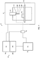
- a machine tool apparatus 2 comprising a machine tool 4, a controller 6, a PC 8 and a transmitter/receiver interface 10.
- the machine tool 4 comprises motors (not shown) for moving a spindle 12 which holds an analogue probe 14 relative to a workpiece 16 located on a table 15.
- the location of the spindle 12 (and hence the analogue probe 14) is accurately measured in a known manner using encoders or the like.
- Such measurements provide spindle position data defined in the machine co-ordinate system (x, y, z).
- a numerical controller (NC) 18 (which is part of the controller 6) controls x, y, z movement of the spindle 12 within the work area of the machine tool and also received data relating to the spindle position.
- relative movement in any or all of the x, y and z dimensions could be provided by movement of the table 15 relative to the spindle.
- relative rotational movement of the analogue probe 14 and workpiece 16 could be provided by a part of the spindle 12 (e.g. a rotating/articulated head mounted on the spindle) and/or a part of table 15 (e.g. a rotary table).
- movement might be restricted to fewer dimensions, e.g. only x, and/or y.
- the embodiment described comprises a cartesian machine tool, whereas will be understood this need not necessarily be the case and could be instance be a non-cartesian machine tool.
- many other different types of machine tools including lathes, and parallel-kinematic machines, and robot arms are known and could be used with the invention.
- the analogue probe 14 is a contact analogue probe which comprises a probe body 20, a workpiece contacting stylus 22 extending from the probe body 20, and has a surface detection region in the form of a workpiece contacting tip 24 (which in this case is in the form of a spherical stylus ball) at the distal end of the stylus 22.
- the analogue probe 14 measures deflection of the stylus 22 in a probe geometry system (a, b, c). (However, as will be understood, this need not necessarily be the case, and for instance the analogue probe could measure deflection in only 1 or 2 dimensions, or even provide an output indicative of the extent of deflection, without any indication of the direction of deflection).
- the probe 14 also comprises a transmitter/receiver (not shown) that wirelessly communicates with the transmitter/receiver interface 10 (e.g. via a radio, optical or other wireless transmission mechanism).
- analogue measurement probes have a limited measurement range. For instance with regard to contact analogue probes, they can have a physical maximum amount by which they can be deflected in the x, y and z dimensions. Not only this, but it can be that the probe is configured such that it works optimally within a certain sub-range of the maximum physical range.
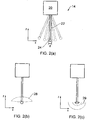
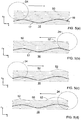
- Figure 2(a) illustrates the analogue probe of Figure 1 , and the solid line represents the position of the stylus 22 at a rest (e.g. undeflected) position. The outermost stylus positions shown in dashed lines represent the maximum physical deflection of the stylus in the x-dimension.
- the probe is configured such that it is most accurate when the stylus is deflected by an amount less than the maximum physical deflection. It could also be that the probe is configured such that it is most accurate when the stylus is deflected by a minimum lower threshold.
- the analogue probe 14 could have a first, e.g. preferred, measurement range, the upper and lower boundaries of which are shown by stylus positions shown in Figure 2(a) as dotted lines. Accordingly, as can be seen there is a dead space 'd' (in the x-dimension) in the middle close to the stylus' rest position which is outside the preferred measurement range.
- the dotted line 28 shown in Figure 2(b) schematically illustrates the scope of the analogue probe's 14 preferred measurement range taken in the x and z dimensions. As will be understood, such a range actually extends in a three dimensions, and hence is actually approximately the shape of a squashed hemisphere with a small hole cut out in the middle.
- the dotted lines of Figure 2(c) also schematically illustrate the preferred measurement range for a non-contact probe, such as an inductance probe.
- the inner and outer dotted lines represent the minimum and maximum probe/workpiece separation boundaries for optimum measuring performance.
- the preferred measuring range shown for the non-contact probe could be the entire measuring range or only a subset of the entire measuring range for the probe.
- the entire measuring range could be considered to be what can be referred to as the non-contact probe's surface detecting region.
- the size of the preferred measuring range will vary from probe to probe.
- a contact analogue probe it could be for example not more than +/-0.8 mm in any given dimension, for example not more than +/-0.725mm in any given dimension, for instance not more than +/-0.5mm in any given dimension, for example in some circumstances not more than +/-0.3mm in any given dimension (taken from the stylus rest position).
- a dead-zone immediately around the stylus position through which the stylus has to be deflected beyond before it enters the preferred measuring range which could be for example not less than +/- 0.2mm in any given dimension from the stylus rest position, for instance not less than +/-0.1mm in any given dimension from the stylus rest position, e.g. not less than +/- 0.125mm in any given dimension (again, measured from the stylus rest position).
- the present invention departs from the traditional view that the probe must be maintained such that along the nominal measurement line on the surface of the object the probe always collects data within its preferred measurement range.
- the invention enables measurements along the nominal measurement line to be obtained both within and outside the probe's preferred measurement range.
- certain undesirable situations are avoided. For instance, it can be preferred that in the case of a contact analogue probe that over deflection of the probe is avoided, especially over deflection that could risk the stylus or probe breaking. In the case of non-contact analogue probes, it could be preferred that contact between the probe and object is avoided altogether. Accordingly, the techniques disclose below enable scanned measurement data to be obtained quickly whilst avoiding such undesirable situations.
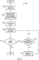
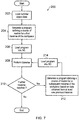
- FIG. 3 illustrates the general procedure 100 involved according to one embodiment of the invention.
- the method starts at step 102 at which point a model of the part to be measured is loaded into the PC 8. As will be understood, this step might not be performed in embodiments in which the workpiece to be measured is unknown.
- a program defining a course of motion for the analogue probe 14 to obtain scanned measurement data of the workpiece 16 is generated.
- the program can also define a course of motion of the workpiece 16.
- step 104 comprises planning the relative course of motion between the analogue probe 14 and the workpiece 16 so that the analogue probe 14 can collect scanned measurement data regarding the workpiece 16.
- the course of motion is configured such that analogue probe and workpiece will traverse back and forth across each other a plurality of times, as will be clearer from the description below in connection with Figures 4 to 6 .
- the program is loaded into the NC 18 via the API 26.
- the NC 18 interprets the program's instructions and generates motor control signals which are used to instruct the machine tool's 4 motors (not shown) so as to move the analogue probe 14 in accordance with one of the traverses defined by the program.
- measurement data is recorded which comprises a number of procedures.
- spindle position data (x, y, z) (which as mentioned above is provided by encoders on the machine tool 4) is passed to the PC 8 via the NC 18.
- probe deflection data (a, b, c) (which as mentioned above is obtained by the analogue probe) is also passed to the PC 8 via the probe transmitter/receiver interface 10.
- the PC 8 combines the spindle position data (x, y, z) and the probe deflection data (a, b, c) to provide a set of measurements that define the position of a surface within the machine co-ordinate geometry.
- the PC 8 determines if from that scan the data from the analogue probe 14 obtained on the traverse just completed was entirely within its preferred measurement range. If so, then the process ends as all relevant measurement data has been obtained. If not, then control proceeds to step 112 at which point the PC 8 determines if, based on knowledge of the future course of motion and also the measurement data collected on the traverse just executed (and/or other previous traverses), whether the analogue probe 14 is likely to exceed its maximum preferred deflection. If so, then at step 114 it manipulates the program in the NC 18 and/or variables referred to by the program loaded in the NC 18 so as to ensure that this does not happen on such a future traverse. As will be understood, it could be the next traverse that is modified, or some other future traverse or even a number of future traverses.
- steps 112 and 114 can be performed very quickly if the NC 18 receives the probe deflection data and performs steps 112 and 114 itself.
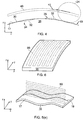
- FIG. 4 a first embodiment shown in Figure 4 there is shown a method of measuring a known part.
- the part is known in that it its nominal shape, dimensions and location are known.
- the nominal shape is illustrated by solid line 30, whereas deviations from its actual shape are illustrated by dotted lines 32.
- the actual shape 32 deviates from the nominal or expected shape due to inaccuracies in manufacturing.
- the actual shape comprises an unexpected dip 34 and a lump 35 in its shape.
- the predetermined course of motion comprises two traverses along the same nominal measurement line 19 (seen more easily in Figure 5(e) ) on the surface 17 of the object 16, but wherein the nominal offset distance between the surface of the object and the nominal centre point of the stylus ball 24 is different for the two traverses, so as to ensure that such deviations can also be measured within the analogue probe's preferred measurement range.
- the nominal position of the stylus ball's 24 centre point along the course of motion is shown by the dotted line 40.
- the first traverse is the one that is furthest away from the surface 17 of the workpiece 16. Due to the unexpected dip in the surface 17 of the workpiece 16, in accordance with Figure 3 , it will be determined at step 110 that not all of the measurements along the length of the traverse were obtained within the analogue probe's preferred measurement range. Accordingly, the second traverse of the predetermined course of motion is to be performed. However, as mentioned above, as well as the unexpected dip 34 there is also an unexpected lump 35 in the surface 17 of the workpiece 16. This lump 35 would have been detected/measured during the first traverse and so in accordance with steps 112 and 114, it is determined whether in the absence of any modification to the predetermined course of motion the lump would cause the probe to over deflect on the second traverse.
- the nominal probe tip centre point deviates from its original nominal course as illustrated by the dashed line 42 in Figure 4 .
- this is achieved by the spindle 12 and hence the probe head 20 shifting from the original predetermined course of motion.
- this could be achieved in other ways.
- the shift in the course of the nominal tip centre point could also be achieved by causing the probe 14 to rotate about a rotational axis of the articulated head.
- the table 15 were movable, then this could be achieved by moving the table.
- the method of the invention also has value when measuring unknown parts, e.g. parts of unknown shape, dimension and/or position.
- unknown parts e.g. parts of unknown shape, dimension and/or position.
- an unknown part could be measured by (with reference to Figure 3 ) instead of at step 102 loading in nominal object data (indeed there is no nominal object data for an unknown part) and at step 104 generating a path which is based on such nominal object data, simply generating a course of motion which comprises moving the contact analogue probe's 14s stylus tip 24 back and forth across the same nominal measurement line 19 on the object a plurality of times, but each time decreasing the nominal separation between the stylus tip's centre point and the surface of the object.
- a predetermined course of motion is generated which initially is configured to move the stylus tip 24 such that its centre point nominally moves back and forth in straight lines along a common nominal measurement line 19 on the surface of the object a plurality of times, with the nominal offset between it and the surface being reduced for each traverse, as illustrated by the dashed line 50.
- the shape of the path of the nominal tip centre is not necessarily the same as the shape of the part and also to ensure that the measurement operation gets all the measurement data it needs, the predetermined course of motion can comprise a much larger number of traverses than is actually required.
- updates to the predetermined course of motion are determined and applied at the end of each traverse (the effect on the nominal position of the probe's centre point along the traverse being illustrated by dotted lines 52) such that for successive traverses over deflection of the stylus 22 is avoided.
- the loop of steps 110 to 114 continues until as shown in Figure 5(d) when measurement data within the measurement probe's preferred measurement range for the length of a traverse and so the method ends and the subsequent predetermined traverses of the object are not performed.
- the method could comprise instead generating the course of motion traverse-by-traverse.
- the method 200 could comprise the user loading at step 202 into the PC 8 nominal object data and then at step 204 generating a program defining a course of motion for the analogue probe to traverse across the object at least once.
- This program is then loaded into the NC 18 at step 206 and the at least one traverse is performed at step 208. If at step 210 it is determined that more data is required about the surface of the workpiece, then control proceeds to step 212 at which point a new program is generated defining a course of motion for the analogue probe to perform at least one further traverse across the surface of the workpiece along a different nominal measurement line. The course of motion for the analogue probe defined by this new program can be generated using surface data obtained from at least one previous traverse. This new program is then loaded in the NC 18 at step 214 and is then performed at step 208. This loop continues until sufficient data regarding the surface of the object has been obtained.
- Figure 6 illustrates an alternative embodiment of the invention in which rather than each traverse of the object taking place along the same nominal measurement line on the surface of the object, the nominal measurement line on the surface of the object is different for different traverses.
- the nominal path of the probe tip centre point along the surface of the object is illustrated by dotted line 60, from which it can be seen that the path comprises a series of traverses across the surface 17 of the workpiece 16.
- the form of the nominal measurement line for each traverse is substantially identical, and extend parallel to each other. However, as will be understood, this need not necessarily be the case.
- the path for a plurality of traverses could be loaded into the NC, and then subsequent traverses could be updated based on previous traverses.
- the method could comprise loading instructions for just a first traverse into the NC, and then instructions for the next traverse(s) could be generated once the first traverse has been completed such that the data from the first traverse can be taken into consideration during the generation of the next traverse.
- the instructions for the first traverse can be generated in many different ways. For instance, if the part is a known part, then it could be assumed that the object to be measured will be as is expected and path can be generated accordingly. Optionally, this could be confirmed by taking select measurements of the object along the nominal measurement line before a scan along the traverse is performed.
- the method could comprise performing an investigative measurement operation to obtain at least some measurement information along the first traverse.
- the investigative measurement operation could comprise performing an operation like that described in Figures 4 or 5 .
- touch-trigger type measurements could be obtained at a number of discrete points along the length of the first traverse prior to performing the first traverse.
- a drip feed technique such as that described above in the background section of this application could be used to perform a first traverse.
- the first traverse could be treated as an unknown traverse, and subsequent traverses treated as known traverses (in that they are generated based on measurement information obtained from at least one previous traverse).
- the method could be configured such that the output of the probe is monitored during subsequent traverses such that if an unexpected measurement occurs, e.g. if the probe goes outside its preferred measurement range, then it reverts back to performing an unknown traverse (for example using a drip feed technique, or a multiple-pass/rastering scanning technique such as that shown in Figures 4 and 5 ).
- the scanning path comprises a plurality of traverses back and forth across the surface of the object.
- the traverses could all take place in the same direction.
- the scanning path doesn't have to comprise a plurality of traverses.
- just one traverse could be performed, which is updated at predetermined intervals.
- the shape of any traverse need not necessarily comprise a generally straight line.
- the path of a traverse could meander in a sideways direction, e.g. in a side-to-side motion.
- the scanning path need not necessarily comprise moving the nominal probe tip centre in a back and forth manner.
- each traverse could comprise moving the nominal probe tip centre in a winding (e.g.
- the traverses can be performed at high speed (e.g. with the workpiece sensing part (e.g. the stylus tip 24) and object travelling relative to each other at least at 16mm/s, preferably at least at 25 mm/s, more preferably at least at 50mm/s, especially preferably at least at 100mm/s, for example at least at 250mm/s) because it doesn't matter whether the probe 14 obtains data below its preferred measuring range and also because the updating of subsequent traverses on the basis of earlier traverses gives the process confidence that the probe 14 and object 16 won't enter into an adverse positional relationship (e.g. such as that the probe's stylus will be caused to over-deflect).
- the workpiece sensing part e.g. the stylus tip 24
Landscapes
- Physics & Mathematics (AREA)
- General Physics & Mathematics (AREA)
- Engineering & Computer Science (AREA)
- Human Computer Interaction (AREA)
- Manufacturing & Machinery (AREA)
- Automation & Control Theory (AREA)
- A Measuring Device Byusing Mechanical Method (AREA)
- Length Measuring Devices With Unspecified Measuring Means (AREA)
Claims (15)
- Verfahren zum Aufbauen eines Messdatensatzes für eine Fläche (17) eines Objekts (16) unter Verwendung eines analogen Messtasters (14), der an einer Werkzeugmaschinenvorrichtung (2) montiert ist und abgetastete Messdaten der Fläche über eine Mehrzahl von versetzten Quergängen (50) erhält, bei denen ein nachfolgender Quergang von einem vorhergehenden Quergang derart versetzt ist, dass über eine Reihe von Quergängen der Oberflächen detektierende Bereich des Analogtasters i) lateral über das Objekt und/oder ii) weg von oder zu dem Objekt voranschreitet, und wobei der Verlauf der Relativbewegung für zumindest einen nachfolgenden Quergang basierend auf Daten erzeugt und/oder aktualisiert wird, die während zumindest einem vorhergehenden Quergang erhalten wurden.
- Verfahren nach Anspruch 1, wobei der Verlauf der Relativbewegung für den zumindest einen nachfolgenden Quergang durch Änderung eines vorbestimmten Bewegungsverlaufs für den nachfolgenden Quergang basierend auf Daten erzeugt und/oder aktualisiert wird, die während zumindest einem vorhergehenden Quergang erhalten wurden.
- Verfahren nach einem der vorhergehenden Ansprüche, wobei zumindest ein nachfolgender Quergang so aktualisiert wird, dass nachteilige Positionsbeziehungen zwischen dem Objekt und dem Analogtaster vermieden werden.
- Verfahren nach Anspruch 3, wobei zumindest ein nachfolgender Quergang so aktualisiert wird, um Positionsbeziehungen zwischen dem Objekt und dem Analogtaster zu vermeiden, was zur Folge hätte, dass der Analogtaster Daten erhält, die eine erste Schwelle überschreiten, wodurch die nachteiligen Positionsbeziehungen vermieden werden.
- Verfahren nach einem der vorherigen Ansprüche, wobei der Analogtaster einen bevorzugten Messbereich aufweist.
- Verfahren nach Anspruch 5, wobei der bevorzugte Messbereich durch zumindest eine obere Grenze definiert ist und wobei zumindest ein nachfolgender Quergang so aktualisiert wird, um Positionsbeziehungen zu vermeiden, die zur Folge hätten, dass der Analogtaster Messungen erhält, die seine obere Grenze überschreiten.
- Verfahren nach einem der vorhergehenden Ansprüche, wobei für jeden Quergang der Analogtaster Messdaten entlang im Wesentlichen der gleichen Nennmesslinie an der Fläche des Objekts erhält.
- Verfahren nach einem der Ansprüche 1 bis 5, wobei für jeden Quergang der Analogtaster Messdaten entlang einer anderen Nennmesslinie an der Fläche des Objekts erhält.
- Verfahren nach Anspruch 8, wobei die Form der Nennmesslinie der Quergängen im Wesentlichen identisch ist.
- Verfahren nach Anspruch 9, wobei die Nennmesslinien sich im Wesentlichen parallel zueinander erstrecken.
- Verfahren nach einem der vorhergehenden Ansprüche, wobei der Analogtaster ein Kontaktanalogtaster ist.
- Verfahren zum Messen eines Merkmals eines Objekts unter Verwendung eines an einer Werkzeugmaschinenvorrichtung montierten Analogtasters, wobei das Verfahren umfasst, dass:in den Controller der Werkzeugmaschine ein vorbestimmter Bewegungsverlauf geladen wird, entlang dem sich der Analogtaster und das Objekt relativ zueinander bewegen können, um so abgetastete Messdaten bezüglich des Merkmals zu sammeln;ein Abtastbetrieb durch relatives Bewegen des Analogtasters und/oder Objekts gemäß dem vorbestimmten Bewegungsverlauf ausgeführt wird;wobei der vorbestimmte Bewegungsverlauf an zumindest einem einer Anzahl vorbestimmter Punkte entlang des vorbestimmten Bewegungsverlaufs basierend auf vorher gesammelten abgetasteten Messdaten aktualisiert wird.
- Computerprogramm, mit Anweisungen, die bei Ausführung durch die Werkzeugmaschinenvorrichtung bewirken, dass die Werkzeugmaschinenvorrichtung das Verfahren nach einem der vorhergehenden Ansprüche ausführt.
- Computerlesbares Medium, das Anweisungen umfasst, die bei Ausführung durch eine Werkzeugmaschinenvorrichtung bewirken, dass die Werkzeugmaschinenvorrichtung das Verfahren nach einem der Ansprüche 1 bis 12 ausführt.
- Werkzeugmaschinenvorrichtung (2) mit einer Werkzeugmaschine (4) und einem analogen Messtaster (14), der an der Werkzeugmaschine montiert ist, wobei die Werkzeugmaschinenvorrichtung derart konfiguriert ist, den analogen Messtaster so zu bewegen, dass ein Messdatensatz für eine Fläche (17) eines Objekts (16) unter Verwendung der Analogmessung durch Erhalten abgetasteter Messdaten der Fläche über eine Mehrzahl versetzter Quergängen (50) aufgebaut wird, in welchen ein nachfolgender Quergang von einem vorhergehenden Quergang derart versetzt ist, dass über eine Reihe von Quergängen der Oberflächen detektierende Bereiche des Analogtasters i) lateral über das Objekt und/oder ii) weg von oder zu dem Objekt voranschreitet, und wobei der Verlauf der Relativbewegung für zumindest einen nachfolgenden Quergang basierend auf Daten erzeugt und/oder aktualisiert wird, die während zumindest einem vorhergehenden Quergang erhalten wurden.
Priority Applications (1)
| Application Number | Priority Date | Filing Date | Title |
|---|---|---|---|
| EP13719595.4A EP2839240B1 (de) | 2012-04-18 | 2013-04-16 | Verfahren zur analogmessungsabtastung auf einem maschinenwerkzeug und entsprechendes maschinenwerkzeug |
Applications Claiming Priority (4)
| Application Number | Priority Date | Filing Date | Title |
|---|---|---|---|
| EP12250093 | 2012-04-18 | ||
| US201261720323P | 2012-10-30 | 2012-10-30 | |
| EP13719595.4A EP2839240B1 (de) | 2012-04-18 | 2013-04-16 | Verfahren zur analogmessungsabtastung auf einem maschinenwerkzeug und entsprechendes maschinenwerkzeug |
| PCT/GB2013/050964 WO2013156765A1 (en) | 2012-04-18 | 2013-04-16 | A method of analogue measurement scanning on a machine tool and corresponding machine tool apparatus |
Publications (2)
| Publication Number | Publication Date |
|---|---|
| EP2839240A1 EP2839240A1 (de) | 2015-02-25 |
| EP2839240B1 true EP2839240B1 (de) | 2017-09-06 |
Family
ID=49382986
Family Applications (1)
| Application Number | Title | Priority Date | Filing Date |
|---|---|---|---|
| EP13719595.4A Active EP2839240B1 (de) | 2012-04-18 | 2013-04-16 | Verfahren zur analogmessungsabtastung auf einem maschinenwerkzeug und entsprechendes maschinenwerkzeug |
Country Status (6)
| Country | Link |
|---|---|
| US (1) | US9726481B2 (de) |
| EP (1) | EP2839240B1 (de) |
| JP (1) | JP6346167B2 (de) |
| CN (1) | CN104969028B (de) |
| TW (1) | TWI503523B (de) |
| WO (1) | WO2013156765A1 (de) |
Families Citing this family (16)
| Publication number | Priority date | Publication date | Assignee | Title |
|---|---|---|---|---|
| US9366519B2 (en) * | 2011-10-06 | 2016-06-14 | Renishaw Plc | Measurement method |
| EP2839241B1 (de) * | 2012-04-18 | 2018-08-08 | Renishaw PLC | Verfahren zum finden eines merkmals eines objektes anhand einer werkzeugmaschine und entsprechende werkzeugmaschinenvorrichtung |
| JP6345171B2 (ja) * | 2012-04-18 | 2018-06-20 | レニショウ パブリック リミテッド カンパニーRenishaw Public Limited Company | 工作機械における測定方法および対応する工作機械装置 |
| JP6007873B2 (ja) * | 2013-08-30 | 2016-10-12 | トヨタ自動車株式会社 | ロボット及びその制御方法 |
| JP6159647B2 (ja) * | 2013-11-12 | 2017-07-05 | 三菱重工工作機械株式会社 | 工作機械の加工検査ワークを用いた機上計測方法 |
| US10215560B2 (en) * | 2015-03-24 | 2019-02-26 | Kla Tencor Corporation | Method for shape classification of an object |
| GB201505999D0 (en) | 2015-04-09 | 2015-05-27 | Renishaw Plc | Measurement method and apparatus |
| US10545019B2 (en) * | 2015-04-14 | 2020-01-28 | Hexagon Metrology, Inc. | CMM probe path controller and method |
| US9952580B2 (en) * | 2016-01-29 | 2018-04-24 | The Boeing Company | Method and an apparatus for machining a part for an assembly |
| GB201806830D0 (en) * | 2018-04-26 | 2018-06-13 | Renishaw Plc | Surface finish stylus |
| GB201806828D0 (en) * | 2018-04-26 | 2018-06-13 | Renishaw Plc | Surface finish stylus |
| EP3611465A1 (de) * | 2018-08-14 | 2020-02-19 | Renishaw PLC | Verfahren, computerprogramm und vorrichtungen zur messzykluserzeugung in einer touch-trigger-koordinatenmaschine |
| EP3623883A1 (de) | 2018-09-17 | 2020-03-18 | HAAS Schleifmaschinen GmbH | Verfahren und werkzeugmaschine zur bearbeitung von werkstücken unbekannter werkstückgeometrie |
| US10814492B2 (en) * | 2019-02-15 | 2020-10-27 | R-Go Robotics Ltd | Apparatus and method for surface traversing with capacitive sensing of surface |
| JP2022075107A (ja) * | 2020-11-06 | 2022-05-18 | 株式会社ミツトヨ | 形状測定装置および異常検出方法 |
| CN112925263A (zh) * | 2021-01-25 | 2021-06-08 | 深圳市玄羽科技有限公司 | 一种cnc数控机台探头及其控制方法 |
Family Cites Families (62)
| Publication number | Priority date | Publication date | Assignee | Title |
|---|---|---|---|---|
| US4153998A (en) | 1972-09-21 | 1979-05-15 | Rolls-Royce (1971) Limited | Probes |
| US4166323A (en) | 1973-09-14 | 1979-09-04 | Maag Gear-Wheel & Machine Co. Ltd. | Gear tester for profile and lead testing |
| GB1551218A (en) | 1975-05-13 | 1979-08-22 | Rolls Royce | Probe for use in displacement measuring apparatus |
| GB2174216B (en) | 1985-03-19 | 1988-10-26 | Mitutoyo Mfg Co Ltd | Method of operating a coordinate measuring instrument |
| CN85105480A (zh) | 1985-07-17 | 1987-01-14 | 通用电气公司 | 针尖接触式探测系统 |
| GB8713715D0 (en) | 1987-06-11 | 1987-07-15 | Renishaw Plc | Workpiece inspection method |
| JPH02145908A (ja) | 1988-11-28 | 1990-06-05 | Okuma Mach Works Ltd | デジタイジング装置におけるスタイラスのたわみ補正自動設定方法 |
| US5189806A (en) * | 1988-12-19 | 1993-03-02 | Renishaw Plc | Method of and apparatus for scanning the surface of a workpiece |
| GB8908854D0 (en) | 1989-04-19 | 1989-06-07 | Renishaw Plc | Method of and apparatus for scanning the surface of a workpiece |
| GB9110818D0 (en) | 1991-05-21 | 1991-07-10 | Renishaw Metrology Ltd | A method of measuring workpieces using a surface contacting measuring probe |
| DE4245012B4 (de) | 1992-04-14 | 2004-09-23 | Carl Zeiss | Verfahren zur Messung von Formelementen auf einem Koordinatenmeßgerät |
| EP0588512B1 (de) | 1992-09-12 | 1997-04-09 | RENISHAW plc | Verfahren und Gerät zum Abtasten der Oberfläche eines Werkstückes |
| US5948972A (en) | 1994-12-22 | 1999-09-07 | Kla-Tencor Corporation | Dual stage instrument for scanning a specimen |
| GB2302589B (en) | 1995-06-21 | 1998-11-11 | Zeiss Stiftung | Probe head for coordinate measuring machines with a clamping device for clamping the deflectable part of the probe head |
| DE19730471C5 (de) | 1997-07-16 | 2009-02-19 | Hexagon Metrology Gmbh | Verfahren zum Scannen mit einem Koordinatenmeßgerät |
| US6580964B2 (en) | 1998-10-24 | 2003-06-17 | Renishaw Plc | Calibrations of an analogue probe and error mapping |
| JP4660779B2 (ja) | 2000-08-18 | 2011-03-30 | 学校法人 中央大学 | 移動装置の位置誤差評価方法およびその評価結果に基づく移動精度向上方法 |
| JP3905771B2 (ja) | 2001-03-02 | 2007-04-18 | 株式会社ミツトヨ | 測定機の校正方法及び装置 |
| GB0118492D0 (en) | 2001-07-30 | 2001-09-19 | Renishaw Plc | A machine tool control process and apparatus therfor |
| GB0126232D0 (en) * | 2001-11-01 | 2002-01-02 | Renishaw Plc | Calibration of an analogue probe |
| GB0210990D0 (en) | 2002-05-14 | 2002-06-19 | Rolls Royce Plc | Method of generating an inspection program and method of generating a visual display |
| GB0215152D0 (en) | 2002-07-01 | 2002-08-07 | Renishaw Plc | Probe or stylus orientation |
| GB0215478D0 (en) | 2002-07-04 | 2002-08-14 | Renishaw Plc | Method of scanning a calibrating system |
| GB0220158D0 (en) | 2002-08-30 | 2002-10-09 | Renishaw Plc | Method of scanning |
| CN1297796C (zh) | 2003-07-02 | 2007-01-31 | 西安交通大学 | 线阵光电传感器层析扫描三维测量方法及其装置 |
| GB0322115D0 (en) | 2003-09-22 | 2003-10-22 | Renishaw Plc | Method of error compensation |
| GB0322362D0 (en) * | 2003-09-24 | 2003-10-22 | Renishaw Plc | Measuring methods for use on machine tools |
| US7543393B2 (en) * | 2003-12-16 | 2009-06-09 | Renishaw Plc | Method of calibrating a scanning system |
| GB0329098D0 (en) | 2003-12-16 | 2004-01-21 | Renishaw Plc | Method of calibrating a scanning system |
| GB0400144D0 (en) | 2004-01-06 | 2004-02-11 | Renishaw Plc | Inspection system |
| EP1555676A3 (de) | 2004-01-14 | 2006-09-13 | FEI Company | Betriebsverfahren eines Rastersondenmikroskops |
| CN1727871A (zh) | 2004-01-14 | 2006-02-01 | Fei公司 | 探针显微镜的操作方法 |
| US20080021672A1 (en) | 2004-03-18 | 2008-01-24 | Renishaw Plc | Scanning an Object |
| JP4782990B2 (ja) | 2004-05-31 | 2011-09-28 | 株式会社ミツトヨ | 表面倣い測定装置、表面倣い測定方法、表面倣い測定プログラムおよび記録媒体 |
| JP4510520B2 (ja) | 2004-06-01 | 2010-07-28 | キヤノン株式会社 | 形状測定方法および形状測定装置 |
| GB0414649D0 (en) | 2004-06-30 | 2004-08-04 | Renishaw Plc | Generation of a CNC machine tool control program |
| GB0417536D0 (en) | 2004-08-06 | 2004-09-08 | Renishaw Plc | The use of surface measurement probes |
| GB0508273D0 (en) | 2005-04-25 | 2005-06-01 | Renishaw Plc | Method for scanning the surface of a workpiece |
| GB0508395D0 (en) * | 2005-04-26 | 2005-06-01 | Renishaw Plc | Method for scanning the surface of a workpiece |
| US20070050089A1 (en) | 2005-09-01 | 2007-03-01 | Yunquan Sun | Method for detecting the position and orientation of holes using robotic vision system |
| GB0608235D0 (en) | 2006-04-26 | 2006-06-07 | Renishaw Plc | Differential calibration |
| GB0611109D0 (en) | 2006-06-06 | 2006-07-19 | Renishaw Plc | A method for measuring workpieces |
| GB0625260D0 (en) | 2006-12-19 | 2007-01-24 | Renishaw Plc | A method for measuring a workpiece using a machine tool |
| GB0703423D0 (en) | 2007-02-22 | 2007-04-04 | Renishaw Plc | Calibration method and apparatus |
| EP1978328B1 (de) | 2007-04-03 | 2015-02-18 | Hexagon Metrology AB | Oszillierende Rastersonde mit konstanter Kontaktkraft |
| GB0707921D0 (en) * | 2007-04-24 | 2007-05-30 | Renishaw Plc | Apparatus and method for surface measurement |
| EP2142878B1 (de) | 2007-04-30 | 2018-09-26 | Renishaw PLC | Analogsonde mit temperaturregler und bedienungsverfahren dafür |
| EP1988357B1 (de) | 2007-05-04 | 2018-10-17 | Hexagon Technology Center GmbH | Verfahren und Vorrichtung zur Koordinatenmessung |
| GB0713639D0 (en) | 2007-07-13 | 2007-08-22 | Renishaw Plc | Error correction |
| GB0716218D0 (en) * | 2007-08-20 | 2007-09-26 | Renishaw Plc | Measurement path generation |
| JP5091702B2 (ja) | 2008-02-04 | 2012-12-05 | 株式会社ミツトヨ | プローブの真直度測定方法 |
| US7752000B2 (en) | 2008-05-02 | 2010-07-06 | Qcept Technologies, Inc. | Calibration of non-vibrating contact potential difference measurements to detect surface variations that are perpendicular to the direction of sensor motion |
| JP4611403B2 (ja) | 2008-06-03 | 2011-01-12 | パナソニック株式会社 | 形状測定装置及び形状測定方法 |
| CN102197274B (zh) | 2008-10-29 | 2015-03-25 | 瑞尼斯豪公司 | 用于坐标测量系统的方法 |
| GB0900878D0 (en) | 2009-01-20 | 2009-03-04 | Renishaw Plc | Method for optimising a measurement cycle |
| EP2290486A1 (de) | 2009-08-28 | 2011-03-02 | Renishaw plc | Kalibrierungsverfahren für Werkzeugmaschine |
| JP5281992B2 (ja) | 2009-08-28 | 2013-09-04 | 株式会社日立製作所 | 走査型プローブ顕微鏡及びそれを用いた計測方法 |
| JP5439157B2 (ja) | 2009-12-22 | 2014-03-12 | 三菱重工業株式会社 | 歯車測定方法 |
| BR112013006042A2 (pt) | 2010-09-13 | 2020-08-04 | Hexagon Tecnology Center Gmbh | método e aparelho para controle de uma máquina de medição de coordenadas de varredura de superfície. |
| CN103328919B (zh) | 2011-01-19 | 2016-08-17 | 瑞尼斯豪公司 | 用于机床设备的模拟测量探头和操作方法 |
| US9366519B2 (en) * | 2011-10-06 | 2016-06-14 | Renishaw Plc | Measurement method |
| EP2839241B1 (de) * | 2012-04-18 | 2018-08-08 | Renishaw PLC | Verfahren zum finden eines merkmals eines objektes anhand einer werkzeugmaschine und entsprechende werkzeugmaschinenvorrichtung |
-
2013
- 2013-04-16 WO PCT/GB2013/050964 patent/WO2013156765A1/en active Application Filing
- 2013-04-16 JP JP2015506298A patent/JP6346167B2/ja active Active
- 2013-04-16 CN CN201380031456.8A patent/CN104969028B/zh active Active
- 2013-04-16 EP EP13719595.4A patent/EP2839240B1/de active Active
- 2013-04-16 US US14/391,837 patent/US9726481B2/en active Active
- 2013-04-18 TW TW102113862A patent/TWI503523B/zh active
Non-Patent Citations (1)
| Title |
|---|
| None * |
Also Published As
| Publication number | Publication date |
|---|---|
| US20150121710A1 (en) | 2015-05-07 |
| CN104969028B (zh) | 2018-06-01 |
| EP2839240A1 (de) | 2015-02-25 |
| TWI503523B (zh) | 2015-10-11 |
| JP6346167B2 (ja) | 2018-06-20 |
| JP2015531852A (ja) | 2015-11-05 |
| TW201350791A (zh) | 2013-12-16 |
| US9726481B2 (en) | 2017-08-08 |
| CN104969028A (zh) | 2015-10-07 |
| WO2013156765A1 (en) | 2013-10-24 |
Similar Documents
| Publication | Publication Date | Title |
|---|---|---|
| EP2839240B1 (de) | Verfahren zur analogmessungsabtastung auf einem maschinenwerkzeug und entsprechendes maschinenwerkzeug | |
| US10678208B2 (en) | Method of measurement on a machine tool | |
| US9952028B2 (en) | Method of finding a feature using a machine tool | |
| EP2102589B1 (de) | Verfahren zur messung eines werkstücks unter verwendung einer bearbeitungsmaschine | |
| US11794299B2 (en) | Calibration method and method of obtaining workpiece information | |
| EP3519766B1 (de) | Verfahren und vorrichtung zum messen eines objekts | |
| TWI449589B (zh) | 刀具參數測量系統及方法 | |
| JP4950443B2 (ja) | キャリブレーションゲージ |
Legal Events
| Date | Code | Title | Description |
|---|---|---|---|
| PUAI | Public reference made under article 153(3) epc to a published international application that has entered the european phase |
Free format text: ORIGINAL CODE: 0009012 |
|
| 17P | Request for examination filed |
Effective date: 20141111 |
|
| AK | Designated contracting states |
Kind code of ref document: A1 Designated state(s): AL AT BE BG CH CY CZ DE DK EE ES FI FR GB GR HR HU IE IS IT LI LT LU LV MC MK MT NL NO PL PT RO RS SE SI SK SM TR |
|
| AX | Request for extension of the european patent |
Extension state: BA ME |
|
| DAX | Request for extension of the european patent (deleted) | ||
| GRAP | Despatch of communication of intention to grant a patent |
Free format text: ORIGINAL CODE: EPIDOSNIGR1 |
|
| INTG | Intention to grant announced |
Effective date: 20170405 |
|
| GRAS | Grant fee paid |
Free format text: ORIGINAL CODE: EPIDOSNIGR3 |
|
| GRAA | (expected) grant |
Free format text: ORIGINAL CODE: 0009210 |
|
| AK | Designated contracting states |
Kind code of ref document: B1 Designated state(s): AL AT BE BG CH CY CZ DE DK EE ES FI FR GB GR HR HU IE IS IT LI LT LU LV MC MK MT NL NO PL PT RO RS SE SI SK SM TR |
|
| REG | Reference to a national code |
Ref country code: GB Ref legal event code: FG4D |
|
| REG | Reference to a national code |
Ref country code: CH Ref legal event code: EP Ref country code: AT Ref legal event code: REF Ref document number: 926359 Country of ref document: AT Kind code of ref document: T Effective date: 20170915 |
|
| REG | Reference to a national code |
Ref country code: IE Ref legal event code: FG4D |
|
| REG | Reference to a national code |
Ref country code: DE Ref legal event code: R096 Ref document number: 602013026128 Country of ref document: DE |
|
| REG | Reference to a national code |
Ref country code: NL Ref legal event code: MP Effective date: 20170906 |
|
| REG | Reference to a national code |
Ref country code: LT Ref legal event code: MG4D |
|
| PG25 | Lapsed in a contracting state [announced via postgrant information from national office to epo] |
Ref country code: NO Free format text: LAPSE BECAUSE OF FAILURE TO SUBMIT A TRANSLATION OF THE DESCRIPTION OR TO PAY THE FEE WITHIN THE PRESCRIBED TIME-LIMIT Effective date: 20171206 Ref country code: LT Free format text: LAPSE BECAUSE OF FAILURE TO SUBMIT A TRANSLATION OF THE DESCRIPTION OR TO PAY THE FEE WITHIN THE PRESCRIBED TIME-LIMIT Effective date: 20170906 Ref country code: SE Free format text: LAPSE BECAUSE OF FAILURE TO SUBMIT A TRANSLATION OF THE DESCRIPTION OR TO PAY THE FEE WITHIN THE PRESCRIBED TIME-LIMIT Effective date: 20170906 Ref country code: HR Free format text: LAPSE BECAUSE OF FAILURE TO SUBMIT A TRANSLATION OF THE DESCRIPTION OR TO PAY THE FEE WITHIN THE PRESCRIBED TIME-LIMIT Effective date: 20170906 Ref country code: FI Free format text: LAPSE BECAUSE OF FAILURE TO SUBMIT A TRANSLATION OF THE DESCRIPTION OR TO PAY THE FEE WITHIN THE PRESCRIBED TIME-LIMIT Effective date: 20170906 |
|
| REG | Reference to a national code |
Ref country code: AT Ref legal event code: MK05 Ref document number: 926359 Country of ref document: AT Kind code of ref document: T Effective date: 20170906 |
|
| PG25 | Lapsed in a contracting state [announced via postgrant information from national office to epo] |
Ref country code: GR Free format text: LAPSE BECAUSE OF FAILURE TO SUBMIT A TRANSLATION OF THE DESCRIPTION OR TO PAY THE FEE WITHIN THE PRESCRIBED TIME-LIMIT Effective date: 20171207 Ref country code: BG Free format text: LAPSE BECAUSE OF FAILURE TO SUBMIT A TRANSLATION OF THE DESCRIPTION OR TO PAY THE FEE WITHIN THE PRESCRIBED TIME-LIMIT Effective date: 20171206 Ref country code: RS Free format text: LAPSE BECAUSE OF FAILURE TO SUBMIT A TRANSLATION OF THE DESCRIPTION OR TO PAY THE FEE WITHIN THE PRESCRIBED TIME-LIMIT Effective date: 20170906 Ref country code: LV Free format text: LAPSE BECAUSE OF FAILURE TO SUBMIT A TRANSLATION OF THE DESCRIPTION OR TO PAY THE FEE WITHIN THE PRESCRIBED TIME-LIMIT Effective date: 20170906 Ref country code: ES Free format text: LAPSE BECAUSE OF FAILURE TO SUBMIT A TRANSLATION OF THE DESCRIPTION OR TO PAY THE FEE WITHIN THE PRESCRIBED TIME-LIMIT Effective date: 20170906 |
|
| PG25 | Lapsed in a contracting state [announced via postgrant information from national office to epo] |
Ref country code: NL Free format text: LAPSE BECAUSE OF FAILURE TO SUBMIT A TRANSLATION OF THE DESCRIPTION OR TO PAY THE FEE WITHIN THE PRESCRIBED TIME-LIMIT Effective date: 20170906 |
|
| PG25 | Lapsed in a contracting state [announced via postgrant information from national office to epo] |
Ref country code: CZ Free format text: LAPSE BECAUSE OF FAILURE TO SUBMIT A TRANSLATION OF THE DESCRIPTION OR TO PAY THE FEE WITHIN THE PRESCRIBED TIME-LIMIT Effective date: 20170906 Ref country code: PL Free format text: LAPSE BECAUSE OF FAILURE TO SUBMIT A TRANSLATION OF THE DESCRIPTION OR TO PAY THE FEE WITHIN THE PRESCRIBED TIME-LIMIT Effective date: 20170906 Ref country code: RO Free format text: LAPSE BECAUSE OF FAILURE TO SUBMIT A TRANSLATION OF THE DESCRIPTION OR TO PAY THE FEE WITHIN THE PRESCRIBED TIME-LIMIT Effective date: 20170906 |
|
| PG25 | Lapsed in a contracting state [announced via postgrant information from national office to epo] |
Ref country code: EE Free format text: LAPSE BECAUSE OF FAILURE TO SUBMIT A TRANSLATION OF THE DESCRIPTION OR TO PAY THE FEE WITHIN THE PRESCRIBED TIME-LIMIT Effective date: 20170906 Ref country code: SK Free format text: LAPSE BECAUSE OF FAILURE TO SUBMIT A TRANSLATION OF THE DESCRIPTION OR TO PAY THE FEE WITHIN THE PRESCRIBED TIME-LIMIT Effective date: 20170906 Ref country code: SM Free format text: LAPSE BECAUSE OF FAILURE TO SUBMIT A TRANSLATION OF THE DESCRIPTION OR TO PAY THE FEE WITHIN THE PRESCRIBED TIME-LIMIT Effective date: 20170906 Ref country code: IS Free format text: LAPSE BECAUSE OF FAILURE TO SUBMIT A TRANSLATION OF THE DESCRIPTION OR TO PAY THE FEE WITHIN THE PRESCRIBED TIME-LIMIT Effective date: 20180106 Ref country code: AT Free format text: LAPSE BECAUSE OF FAILURE TO SUBMIT A TRANSLATION OF THE DESCRIPTION OR TO PAY THE FEE WITHIN THE PRESCRIBED TIME-LIMIT Effective date: 20170906 |
|
| REG | Reference to a national code |
Ref country code: DE Ref legal event code: R097 Ref document number: 602013026128 Country of ref document: DE |
|
| PLBE | No opposition filed within time limit |
Free format text: ORIGINAL CODE: 0009261 |
|
| STAA | Information on the status of an ep patent application or granted ep patent |
Free format text: STATUS: NO OPPOSITION FILED WITHIN TIME LIMIT |
|
| PG25 | Lapsed in a contracting state [announced via postgrant information from national office to epo] |
Ref country code: DK Free format text: LAPSE BECAUSE OF FAILURE TO SUBMIT A TRANSLATION OF THE DESCRIPTION OR TO PAY THE FEE WITHIN THE PRESCRIBED TIME-LIMIT Effective date: 20170906 |
|
| 26N | No opposition filed |
Effective date: 20180607 |
|
| PG25 | Lapsed in a contracting state [announced via postgrant information from national office to epo] |
Ref country code: SI Free format text: LAPSE BECAUSE OF FAILURE TO SUBMIT A TRANSLATION OF THE DESCRIPTION OR TO PAY THE FEE WITHIN THE PRESCRIBED TIME-LIMIT Effective date: 20170906 |
|
| PG25 | Lapsed in a contracting state [announced via postgrant information from national office to epo] |
Ref country code: MC Free format text: LAPSE BECAUSE OF FAILURE TO SUBMIT A TRANSLATION OF THE DESCRIPTION OR TO PAY THE FEE WITHIN THE PRESCRIBED TIME-LIMIT Effective date: 20170906 |
|
| REG | Reference to a national code |
Ref country code: CH Ref legal event code: PL |
|
| REG | Reference to a national code |
Ref country code: BE Ref legal event code: MM Effective date: 20180430 |
|
| REG | Reference to a national code |
Ref country code: IE Ref legal event code: MM4A |
|
| PG25 | Lapsed in a contracting state [announced via postgrant information from national office to epo] |
Ref country code: LU Free format text: LAPSE BECAUSE OF NON-PAYMENT OF DUE FEES Effective date: 20180416 |
|
| PG25 | Lapsed in a contracting state [announced via postgrant information from national office to epo] |
Ref country code: CH Free format text: LAPSE BECAUSE OF NON-PAYMENT OF DUE FEES Effective date: 20180430 Ref country code: BE Free format text: LAPSE BECAUSE OF NON-PAYMENT OF DUE FEES Effective date: 20180430 Ref country code: LI Free format text: LAPSE BECAUSE OF NON-PAYMENT OF DUE FEES Effective date: 20180430 |
|
| PG25 | Lapsed in a contracting state [announced via postgrant information from national office to epo] |
Ref country code: FR Free format text: LAPSE BECAUSE OF NON-PAYMENT OF DUE FEES Effective date: 20180430 Ref country code: IE Free format text: LAPSE BECAUSE OF NON-PAYMENT OF DUE FEES Effective date: 20180416 |
|
| PG25 | Lapsed in a contracting state [announced via postgrant information from national office to epo] |
Ref country code: MT Free format text: LAPSE BECAUSE OF NON-PAYMENT OF DUE FEES Effective date: 20180416 |
|
| PG25 | Lapsed in a contracting state [announced via postgrant information from national office to epo] |
Ref country code: TR Free format text: LAPSE BECAUSE OF FAILURE TO SUBMIT A TRANSLATION OF THE DESCRIPTION OR TO PAY THE FEE WITHIN THE PRESCRIBED TIME-LIMIT Effective date: 20170906 |
|
| PG25 | Lapsed in a contracting state [announced via postgrant information from national office to epo] |
Ref country code: HU Free format text: LAPSE BECAUSE OF FAILURE TO SUBMIT A TRANSLATION OF THE DESCRIPTION OR TO PAY THE FEE WITHIN THE PRESCRIBED TIME-LIMIT; INVALID AB INITIO Effective date: 20130416 Ref country code: PT Free format text: LAPSE BECAUSE OF FAILURE TO SUBMIT A TRANSLATION OF THE DESCRIPTION OR TO PAY THE FEE WITHIN THE PRESCRIBED TIME-LIMIT Effective date: 20170906 |
|
| PG25 | Lapsed in a contracting state [announced via postgrant information from national office to epo] |
Ref country code: MK Free format text: LAPSE BECAUSE OF NON-PAYMENT OF DUE FEES Effective date: 20170906 Ref country code: CY Free format text: LAPSE BECAUSE OF FAILURE TO SUBMIT A TRANSLATION OF THE DESCRIPTION OR TO PAY THE FEE WITHIN THE PRESCRIBED TIME-LIMIT Effective date: 20170906 |
|
| PG25 | Lapsed in a contracting state [announced via postgrant information from national office to epo] |
Ref country code: AL Free format text: LAPSE BECAUSE OF FAILURE TO SUBMIT A TRANSLATION OF THE DESCRIPTION OR TO PAY THE FEE WITHIN THE PRESCRIBED TIME-LIMIT Effective date: 20170906 |
|
| P01 | Opt-out of the competence of the unified patent court (upc) registered |
Effective date: 20230602 |
|
| PGFP | Annual fee paid to national office [announced via postgrant information from national office to epo] |
Ref country code: IT Payment date: 20230421 Year of fee payment: 11 Ref country code: DE Payment date: 20230427 Year of fee payment: 11 |
|
| PGFP | Annual fee paid to national office [announced via postgrant information from national office to epo] |
Ref country code: GB Payment date: 20230418 Year of fee payment: 11 |