EP2836168B1 - Methods for additive manufacturing of implant components - Google Patents
Methods for additive manufacturing of implant components Download PDFInfo
- Publication number
- EP2836168B1 EP2836168B1 EP13775348.9A EP13775348A EP2836168B1 EP 2836168 B1 EP2836168 B1 EP 2836168B1 EP 13775348 A EP13775348 A EP 13775348A EP 2836168 B1 EP2836168 B1 EP 2836168B1
- Authority
- EP
- European Patent Office
- Prior art keywords
- implant
- support structures
- manufacturing
- patient
- design
- Prior art date
- Legal status (The legal status is an assumption and is not a legal conclusion. Google has not performed a legal analysis and makes no representation as to the accuracy of the status listed.)
- Active
Links
Images


Classifications
-
- A—HUMAN NECESSITIES
- A61—MEDICAL OR VETERINARY SCIENCE; HYGIENE
- A61F—FILTERS IMPLANTABLE INTO BLOOD VESSELS; PROSTHESES; DEVICES PROVIDING PATENCY TO, OR PREVENTING COLLAPSING OF, TUBULAR STRUCTURES OF THE BODY, e.g. STENTS; ORTHOPAEDIC, NURSING OR CONTRACEPTIVE DEVICES; FOMENTATION; TREATMENT OR PROTECTION OF EYES OR EARS; BANDAGES, DRESSINGS OR ABSORBENT PADS; FIRST-AID KITS
- A61F2/00—Filters implantable into blood vessels; Prostheses, i.e. artificial substitutes or replacements for parts of the body; Appliances for connecting them with the body; Devices providing patency to, or preventing collapsing of, tubular structures of the body, e.g. stents
- A61F2/02—Prostheses implantable into the body
- A61F2/30—Joints
- A61F2/3094—Designing or manufacturing processes
- A61F2/30942—Designing or manufacturing processes for designing or making customized prostheses, e.g. using templates, CT or NMR scans, finite-element analysis or CAD-CAM techniques
-
- A—HUMAN NECESSITIES
- A61—MEDICAL OR VETERINARY SCIENCE; HYGIENE
- A61F—FILTERS IMPLANTABLE INTO BLOOD VESSELS; PROSTHESES; DEVICES PROVIDING PATENCY TO, OR PREVENTING COLLAPSING OF, TUBULAR STRUCTURES OF THE BODY, e.g. STENTS; ORTHOPAEDIC, NURSING OR CONTRACEPTIVE DEVICES; FOMENTATION; TREATMENT OR PROTECTION OF EYES OR EARS; BANDAGES, DRESSINGS OR ABSORBENT PADS; FIRST-AID KITS
- A61F2/00—Filters implantable into blood vessels; Prostheses, i.e. artificial substitutes or replacements for parts of the body; Appliances for connecting them with the body; Devices providing patency to, or preventing collapsing of, tubular structures of the body, e.g. stents
- A61F2/02—Prostheses implantable into the body
- A61F2/30—Joints
- A61F2/32—Joints for the hip
- A61F2/36—Femoral heads ; Femoral endoprostheses
-
- A—HUMAN NECESSITIES
- A61—MEDICAL OR VETERINARY SCIENCE; HYGIENE
- A61F—FILTERS IMPLANTABLE INTO BLOOD VESSELS; PROSTHESES; DEVICES PROVIDING PATENCY TO, OR PREVENTING COLLAPSING OF, TUBULAR STRUCTURES OF THE BODY, e.g. STENTS; ORTHOPAEDIC, NURSING OR CONTRACEPTIVE DEVICES; FOMENTATION; TREATMENT OR PROTECTION OF EYES OR EARS; BANDAGES, DRESSINGS OR ABSORBENT PADS; FIRST-AID KITS
- A61F2/00—Filters implantable into blood vessels; Prostheses, i.e. artificial substitutes or replacements for parts of the body; Appliances for connecting them with the body; Devices providing patency to, or preventing collapsing of, tubular structures of the body, e.g. stents
- A61F2/02—Prostheses implantable into the body
- A61F2/30—Joints
- A61F2/38—Joints for elbows or knees
- A61F2/3859—Femoral components
-
- B—PERFORMING OPERATIONS; TRANSPORTING
- B22—CASTING; POWDER METALLURGY
- B22F—WORKING METALLIC POWDER; MANUFACTURE OF ARTICLES FROM METALLIC POWDER; MAKING METALLIC POWDER; APPARATUS OR DEVICES SPECIALLY ADAPTED FOR METALLIC POWDER
- B22F10/00—Additive manufacturing of workpieces or articles from metallic powder
- B22F10/40—Structures for supporting workpieces or articles during manufacture and removed afterwards
- B22F10/47—Structures for supporting workpieces or articles during manufacture and removed afterwards characterised by structural features
-
- B—PERFORMING OPERATIONS; TRANSPORTING
- B22—CASTING; POWDER METALLURGY
- B22F—WORKING METALLIC POWDER; MANUFACTURE OF ARTICLES FROM METALLIC POWDER; MAKING METALLIC POWDER; APPARATUS OR DEVICES SPECIALLY ADAPTED FOR METALLIC POWDER
- B22F3/00—Manufacture of workpieces or articles from metallic powder characterised by the manner of compacting or sintering; Apparatus specially adapted therefor ; Presses and furnaces
- B22F3/02—Compacting only
-
- B—PERFORMING OPERATIONS; TRANSPORTING
- B22—CASTING; POWDER METALLURGY
- B22F—WORKING METALLIC POWDER; MANUFACTURE OF ARTICLES FROM METALLIC POWDER; MAKING METALLIC POWDER; APPARATUS OR DEVICES SPECIALLY ADAPTED FOR METALLIC POWDER
- B22F5/00—Manufacture of workpieces or articles from metallic powder characterised by the special shape of the product
-
- B—PERFORMING OPERATIONS; TRANSPORTING
- B23—MACHINE TOOLS; METAL-WORKING NOT OTHERWISE PROVIDED FOR
- B23K—SOLDERING OR UNSOLDERING; WELDING; CLADDING OR PLATING BY SOLDERING OR WELDING; CUTTING BY APPLYING HEAT LOCALLY, e.g. FLAME CUTTING; WORKING BY LASER BEAM
- B23K15/00—Electron-beam welding or cutting
- B23K15/0046—Welding
- B23K15/0086—Welding welding for purposes other than joining, e.g. built-up welding
-
- B—PERFORMING OPERATIONS; TRANSPORTING
- B23—MACHINE TOOLS; METAL-WORKING NOT OTHERWISE PROVIDED FOR
- B23K—SOLDERING OR UNSOLDERING; WELDING; CLADDING OR PLATING BY SOLDERING OR WELDING; CUTTING BY APPLYING HEAT LOCALLY, e.g. FLAME CUTTING; WORKING BY LASER BEAM
- B23K26/00—Working by laser beam, e.g. welding, cutting or boring
- B23K26/34—Laser welding for purposes other than joining
- B23K26/342—Build-up welding
-
- B—PERFORMING OPERATIONS; TRANSPORTING
- B28—WORKING CEMENT, CLAY, OR STONE
- B28B—SHAPING CLAY OR OTHER CERAMIC COMPOSITIONS; SHAPING SLAG; SHAPING MIXTURES CONTAINING CEMENTITIOUS MATERIAL, e.g. PLASTER
- B28B1/00—Producing shaped prefabricated articles from the material
- B28B1/001—Rapid manufacturing of 3D objects by additive depositing, agglomerating or laminating of material
-
- B—PERFORMING OPERATIONS; TRANSPORTING
- B29—WORKING OF PLASTICS; WORKING OF SUBSTANCES IN A PLASTIC STATE IN GENERAL
- B29C—SHAPING OR JOINING OF PLASTICS; SHAPING OF MATERIAL IN A PLASTIC STATE, NOT OTHERWISE PROVIDED FOR; AFTER-TREATMENT OF THE SHAPED PRODUCTS, e.g. REPAIRING
- B29C64/00—Additive manufacturing, i.e. manufacturing of three-dimensional [3D] objects by additive deposition, additive agglomeration or additive layering, e.g. by 3D printing, stereolithography or selective laser sintering
- B29C64/10—Processes of additive manufacturing
- B29C64/141—Processes of additive manufacturing using only solid materials
- B29C64/153—Processes of additive manufacturing using only solid materials using layers of powder being selectively joined, e.g. by selective laser sintering or melting
-
- B—PERFORMING OPERATIONS; TRANSPORTING
- B33—ADDITIVE MANUFACTURING TECHNOLOGY
- B33Y—ADDITIVE MANUFACTURING, i.e. MANUFACTURING OF THREE-DIMENSIONAL [3-D] OBJECTS BY ADDITIVE DEPOSITION, ADDITIVE AGGLOMERATION OR ADDITIVE LAYERING, e.g. BY 3-D PRINTING, STEREOLITHOGRAPHY OR SELECTIVE LASER SINTERING
- B33Y80/00—Products made by additive manufacturing
-
- A—HUMAN NECESSITIES
- A61—MEDICAL OR VETERINARY SCIENCE; HYGIENE
- A61F—FILTERS IMPLANTABLE INTO BLOOD VESSELS; PROSTHESES; DEVICES PROVIDING PATENCY TO, OR PREVENTING COLLAPSING OF, TUBULAR STRUCTURES OF THE BODY, e.g. STENTS; ORTHOPAEDIC, NURSING OR CONTRACEPTIVE DEVICES; FOMENTATION; TREATMENT OR PROTECTION OF EYES OR EARS; BANDAGES, DRESSINGS OR ABSORBENT PADS; FIRST-AID KITS
- A61F2/00—Filters implantable into blood vessels; Prostheses, i.e. artificial substitutes or replacements for parts of the body; Appliances for connecting them with the body; Devices providing patency to, or preventing collapsing of, tubular structures of the body, e.g. stents
- A61F2/02—Prostheses implantable into the body
- A61F2/30—Joints
- A61F2/30767—Special external or bone-contacting surface, e.g. coating for improving bone ingrowth
- A61F2/30771—Special external or bone-contacting surface, e.g. coating for improving bone ingrowth applied in original prostheses, e.g. holes or grooves
- A61F2002/30878—Special external or bone-contacting surface, e.g. coating for improving bone ingrowth applied in original prostheses, e.g. holes or grooves with non-sharp protrusions, for instance contacting the bone for anchoring, e.g. keels, pegs, pins, posts, shanks, stems, struts
-
- A—HUMAN NECESSITIES
- A61—MEDICAL OR VETERINARY SCIENCE; HYGIENE
- A61F—FILTERS IMPLANTABLE INTO BLOOD VESSELS; PROSTHESES; DEVICES PROVIDING PATENCY TO, OR PREVENTING COLLAPSING OF, TUBULAR STRUCTURES OF THE BODY, e.g. STENTS; ORTHOPAEDIC, NURSING OR CONTRACEPTIVE DEVICES; FOMENTATION; TREATMENT OR PROTECTION OF EYES OR EARS; BANDAGES, DRESSINGS OR ABSORBENT PADS; FIRST-AID KITS
- A61F2/00—Filters implantable into blood vessels; Prostheses, i.e. artificial substitutes or replacements for parts of the body; Appliances for connecting them with the body; Devices providing patency to, or preventing collapsing of, tubular structures of the body, e.g. stents
- A61F2/02—Prostheses implantable into the body
- A61F2/30—Joints
- A61F2/3094—Designing or manufacturing processes
- A61F2/30942—Designing or manufacturing processes for designing or making customized prostheses, e.g. using templates, CT or NMR scans, finite-element analysis or CAD-CAM techniques
- A61F2002/30955—Designing or manufacturing processes for designing or making customized prostheses, e.g. using templates, CT or NMR scans, finite-element analysis or CAD-CAM techniques using finite-element analysis
-
- A—HUMAN NECESSITIES
- A61—MEDICAL OR VETERINARY SCIENCE; HYGIENE
- A61F—FILTERS IMPLANTABLE INTO BLOOD VESSELS; PROSTHESES; DEVICES PROVIDING PATENCY TO, OR PREVENTING COLLAPSING OF, TUBULAR STRUCTURES OF THE BODY, e.g. STENTS; ORTHOPAEDIC, NURSING OR CONTRACEPTIVE DEVICES; FOMENTATION; TREATMENT OR PROTECTION OF EYES OR EARS; BANDAGES, DRESSINGS OR ABSORBENT PADS; FIRST-AID KITS
- A61F2/00—Filters implantable into blood vessels; Prostheses, i.e. artificial substitutes or replacements for parts of the body; Appliances for connecting them with the body; Devices providing patency to, or preventing collapsing of, tubular structures of the body, e.g. stents
- A61F2/02—Prostheses implantable into the body
- A61F2/30—Joints
- A61F2/3094—Designing or manufacturing processes
- A61F2/30942—Designing or manufacturing processes for designing or making customized prostheses, e.g. using templates, CT or NMR scans, finite-element analysis or CAD-CAM techniques
- A61F2002/30962—Designing or manufacturing processes for designing or making customized prostheses, e.g. using templates, CT or NMR scans, finite-element analysis or CAD-CAM techniques using stereolithography
-
- B—PERFORMING OPERATIONS; TRANSPORTING
- B22—CASTING; POWDER METALLURGY
- B22F—WORKING METALLIC POWDER; MANUFACTURE OF ARTICLES FROM METALLIC POWDER; MAKING METALLIC POWDER; APPARATUS OR DEVICES SPECIALLY ADAPTED FOR METALLIC POWDER
- B22F10/00—Additive manufacturing of workpieces or articles from metallic powder
- B22F10/20—Direct sintering or melting
- B22F10/28—Powder bed fusion, e.g. selective laser melting [SLM] or electron beam melting [EBM]
-
- B—PERFORMING OPERATIONS; TRANSPORTING
- B22—CASTING; POWDER METALLURGY
- B22F—WORKING METALLIC POWDER; MANUFACTURE OF ARTICLES FROM METALLIC POWDER; MAKING METALLIC POWDER; APPARATUS OR DEVICES SPECIALLY ADAPTED FOR METALLIC POWDER
- B22F10/00—Additive manufacturing of workpieces or articles from metallic powder
- B22F10/80—Data acquisition or data processing
-
- B—PERFORMING OPERATIONS; TRANSPORTING
- B33—ADDITIVE MANUFACTURING TECHNOLOGY
- B33Y—ADDITIVE MANUFACTURING, i.e. MANUFACTURING OF THREE-DIMENSIONAL [3-D] OBJECTS BY ADDITIVE DEPOSITION, ADDITIVE AGGLOMERATION OR ADDITIVE LAYERING, e.g. BY 3-D PRINTING, STEREOLITHOGRAPHY OR SELECTIVE LASER SINTERING
- B33Y10/00—Processes of additive manufacturing
-
- B—PERFORMING OPERATIONS; TRANSPORTING
- B33—ADDITIVE MANUFACTURING TECHNOLOGY
- B33Y—ADDITIVE MANUFACTURING, i.e. MANUFACTURING OF THREE-DIMENSIONAL [3-D] OBJECTS BY ADDITIVE DEPOSITION, ADDITIVE AGGLOMERATION OR ADDITIVE LAYERING, e.g. BY 3-D PRINTING, STEREOLITHOGRAPHY OR SELECTIVE LASER SINTERING
- B33Y50/00—Data acquisition or data processing for additive manufacturing
- B33Y50/02—Data acquisition or data processing for additive manufacturing for controlling or regulating additive manufacturing processes
-
- Y—GENERAL TAGGING OF NEW TECHNOLOGICAL DEVELOPMENTS; GENERAL TAGGING OF CROSS-SECTIONAL TECHNOLOGIES SPANNING OVER SEVERAL SECTIONS OF THE IPC; TECHNICAL SUBJECTS COVERED BY FORMER USPC CROSS-REFERENCE ART COLLECTIONS [XRACs] AND DIGESTS
- Y02—TECHNOLOGIES OR APPLICATIONS FOR MITIGATION OR ADAPTATION AGAINST CLIMATE CHANGE
- Y02P—CLIMATE CHANGE MITIGATION TECHNOLOGIES IN THE PRODUCTION OR PROCESSING OF GOODS
- Y02P10/00—Technologies related to metal processing
- Y02P10/25—Process efficiency
Definitions
- Embodiments described herein relate to methods for manufacturing implants, implant components and/or related tools using additive metals technologies, including SLM (selective laser melting) technologies. More specifically, various embodiments described herein include methods for improving the SLM manufacture of femoral implant components forming a portion of a patient-adapted knee joint implant.
- SLM selective laser melting
- Surgical implant systems that employed a one-size-fits-all approach to implant design (and even those that utilized a "few-sizes-fit-all" approach, including modularly assembled systems) did not typically require highly accurate information about the patient's anatomy. Instead, such systems utilized gross anatomical measurements such as the maximum bone dimensions at the implant site, as well as the patient weight and age, to determine a "suitable" implant.
- the surgical procedure then concentrated on altering the underlying bony anatomical support structures (e.g., by cutting, drilling and/or otherwise modifying the bone structures) to accommodate the existing contact surfaces of the pre-manufactured implant.
- varying quantities of implants and/or implant components would be manufactured and stockpiled. Once a potential patient was identified, an appropriate implant and/or component would be selected, transported to the surgical location and utilized in the patient's surgical procedure.
- the joint replacement field has come to embrace the concept of "patient-adapted” (i.e., “patient-specific” and/or “patient-engineered”) implant systems.
- patient-adapted i.e., "patient-specific” and/or “patient-engineered” implant systems.
- the surgical implants, associated surgical tools and procedures are designed or otherwise modified to account for and accommodate the individual anatomy of the patient undergoing the surgical procedure.
- Such systems typically utilize non-invasive imaging data, taken of the individual preoperatively, to guide the design and/or selection of the implant, surgical tools, and the planning of the surgical procedure itself.
- Various objectives of these newer systems include (1) reducing the amount of bony anatomy removed to accommodate the implant, (2) designing/selecting an implant that replicates and/or improves the function of the natural joint, (3) increasing the durability and functional lifetime of the implant, (4) simplifying the surgical procedure for the surgeon, (5) reducing patient recovery time and/or discomfort, and (6) improving patient outcomes.
- patient-specific and “patient-engineered” implant systems are created using anatomical information from a particular patient, such systems are generally created after the patient has been designated a "surgical candidate" and undergone non-invasive imaging. But, because such systems are not generally pre-manufactured and stockpiled in multiple sizes (as are traditional systems), there can be a considerable delay between patient diagnosis and the actual surgery, much of which is due to the amount of time necessary to design and manufacture the "patient-specific” and/or "patient-engineered” implant components using patent image data.
- WO 2011/056995 A2 describes methods and devices to create models, implants, and related tools and procedures based on data derived from the existing joint. The data can be used to create model that can be used to analyze the patient's joint and to devise and evaluate a course of corrective action. The data also can be used to create patient-specific and/or patient engineered implants and related tools and procedures.
- a method of additive manufacturing of an implant for repairing a joint of a patient the implant having one or more articular surfaces and one or more bone-facing surfaces, the method comprising aligning a design for the implant relative to a substrate in a manufacturing apparatus, providing one or more support structures contacting one or more portions of the implant to be supported and removing the support structure from the implant, wherein one or more support structures do not contact the one or more articular surfaces.
- the invention is defined in claim 1.
- the embodiments described herein include advancements and improvements in or related to the use of additive manufacturing techniques, including Selective Laser Melting (SLM) manufacturing techniques, in the design, selection, development, manufacturing and/or finishing of patient-specific and/or patient-engineered implant components.
- SLM Selective Laser Melting
- Various embodiments described herein facilitate the production of "patient-specific” or “patient-engineered” implants in a more cost effective and/or efficient manner.
- Various embodiments described herein include methods for improving the strength, quality, performance and/or durability of implant components manufactured using SLM or similar material-additive manufacturing techniques.
- Various embodiments described herein include methods of improving and/or simplifying the post-manufacture processing and/or "finishing' of an implant component manufactured using SLM or similar material-additive manufacturing techniques.
- Various embodiments described herein include methods of assessing and/or optimizing SLM manufacturing methods and/or modifying implant design features to accommodate different limitations associated with SLM manufacturing techniques and processes.
- M and L in certain figures indicate medial and lateral sides of the view, respectively;
- A and “P” in certain figures indicate anterior and posterior sides of the view, respectively;
- S and “I” in certain figures indicate superior and inferior sides of the view, respectively.
- patient-specific implants are generally created after a patient has been identified as a surgical candidate, and the implant is designed and/or selected using imaging data taken of the intended patient's anatomy.
- the process of designing, manufacturing and finishing the implant can involve a number of steps, typically involving multiple vendors, and this process must result in an acceptable implant before the surgery can occur.
- traditional methods of creating of a patient-specific implant from patient imaging data can require more than 4 to 7 weeks, which is a significant delay for both the surgeon and the patient.
- An additional concern relating to the use of patient-specific implants relates to the availability of processing and manufacturing equipment, as well as the assurance that the implant components will be processed and available for the surgical procedure. Because each patient-specific implant is unique, and because a significant amount of time and effort is required to create each implant, it is typical practice to manufacture multiple copies (e.g., a primary and a backup implant) of an implant for a single patient, to ensure that at least one implant survives the manufacturing, finishing and testing processes prior to surgical use. However, because such backup implants are only needed where the primary implant has failed, the constant creation of backup implants leads to unused inventory and unnecessary costs where the primary implant does not get damaged.
- 3-dimensional printing technology also known as Solid Freeform Fabrication or "SFF"
- SFF Solid Freeform Fabrication
- 3D printing techniques have evolved over the past decades to allow the creation of prototypes, mould masters and/or "models" that could be used in metal casting techniques (e.g., lost-wax casting or investment casting).
- SLS Selective Laser Sintering
- SLM Selective Laser Melting
- DMLS Direct Metal Laser Sintering
- LaserCusing Direct Metal Laser Sintering
- SLS allows a range of metallic systems and polymeric material choices in the creation of the physical object
- SLS parts typically (1) have a rough grainy and porous surface finish, (2) experience a relatively large shrink rate causing the part to warp, bow or curl, and (3) have a surface feature detail that is relatively coarse.
- the technique as currently refined also comes with some associated disadvantages, including (1) high temperature gradients resulting in a build-up of thermal stresses, (2) a rapid solidification, leading to the occurrence of segregation phenomena and the presence of non-equilibrium phases, (3) the stability, dimensions and behavior of the particle "melt pool” determines to a great extent the porosity and surface roughness, and (4) the object has a surface roughness created by the layer-wise building techniques (e.g., the "staircase effect").
- the steps of designing an implant component and/or guide tool, and associated methods of manufacturing such objects using additive material technologies such as SLM and SLS, as described herein, can include both configuring one or more features, measurements, and/or dimensions of the implant and/or guide tool (e.g., derived from patient-specific data from a particular patient and adapted for the particular patient), manufacturing and finishing the implant/tool.
- manufacturing can include making the implant component and/or guide tool from starting materials, for example, metals and/or polymers or other materials in solid (e.g., powders or blocks) or liquid form.
- manufacturing can include altering (e.g., machining) an existing implant component and/or guide tool, for example, a standard blank implant component and/or guide tool or an existing implant component and/or guide tool (e.g., selected from a library), as well as post-manufacture machining and/or processing of an implant after manufacture by SLM techniques.
- altering e.g., machining
- an existing implant component and/or guide tool for example, a standard blank implant component and/or guide tool or an existing implant component and/or guide tool (e.g., selected from a library)
- SLM techniques post-manufacture machining and/or processing of an implant after manufacture by SLM techniques.
- the manufacturing techniques to making or altering an implant component and/or guide tool can include any techniques known in the art today and in the future.
- Such techniques include, but are not limited to additive as well as subtractive methods, i.e., methods that add material, for example to a standard blank, and methods that remove material, for example from a standard blank, as well as combinations thereof (i.e., using both additive and subtractive techniques on a single object).
- the design of an implant component and/or guide tool can include manufacturing, for example, using CAM software and additive, subtractive and/or casting manufacturing techniques as described herein.
- an implant component and/or other manufactured object may be altered or modified to accommodate advantages and/or limitations of a specific manufacturing process, such as SLM, which may result in differing designs for a single anatomical situation (e.g., for a single patient anatomy) based on differing manufacturing methods.
- a specific manufacturing process such as SLM
- FIG. 1 depicts a schematic view of equipment and the process used in a typical SLM manufacturing process.
- SLM is a powder bed 8 process that begins with the deposition of a thin layer of powder onto a substrate 30, which can be disposed on a processing table 11.
- a high power laser 6 scans the surface of the powder, generating heat that causes the powder particles to melt (see melted powder 7) and form a melt pool which solidifies as a consolidated layer of material.
- another layer of powder is deposited, which is then subsequently scanned and melted/solidified to form the next layer of the part. This process continues with multiple layers 13 until enough layers of material have been deposited/melted/solidified to create a desired object 9.
- Powder particles that are not melted remain loose and are removed (and can typically be reused) once the component is complete.
- Supports or other features/artifacts are typically required to anchor down certain unsupported features due to shrinkage and/or "curling" of solidifying material. To some extent, this anchoring requirement restricts the process of geometric freedom.
- Various examples described herein include designs and methods to mitigate, reduce and/or eliminate structural and/or processing challenges and/or concerns posed by SLM manufacturing of implant components.
- various examples further include designs and methods that improve, maximize and/or take advantage of structural and/or processing benefits conferred by SLM manufacturing of implant components.
- various additional techniques such as laser polishing or laser rescanning in parallel and/or perpendicular scanning directions (including remelting of previously formed surfaces and/or structures), hot isostatic processing (HIP) processing of manufactured implants, annealing and/or coating (e.g., titanium nitride coating and/or titanium aluminum nitride coating) are contemplated for use with the various examples disclosed herein.
- HIP hot isostatic processing
- the SLM raw material comprises a CrCo powder having an average particle size of between 34 and 54 microns, although larger and/or smaller particles may used with varying degrees of utility (as well as the use of differing size particles in creating a single implant component).
- the deposed particle layer may be approximately 60 microns thick, which, when melted, consolidated and cooled, can create a solid structural layer of approximately 20 microns thickness.
- Some significant features of various examples described herein include various methods, techniques and/or processes to align, orient and/or otherwise position implants or other objects to be manufactured relative to a known "home" or “zero” location and orientation of the SLM manufacturing equipment or portions thereof (e.g., the laser source and/or scanning mechanism). Consistent orientation and location relative to a known position can facilitate the reliable and repeatable manufacturing of implant components in a single machine and/or across multiple machines, and can further assist with identification and/or alleviation of process and/or design defects discovered during or after the manufacturing process. Moreover, proper alignment and/or location of a manufactured object relative to the manufacturing machinery allows a designer and/or operator to predict and/or accommodate for various manufacturing advantages and/or disadvantages inherent in the chosen manufacturing processes.
- an electronic design file (such as a CAD file, for example) for a knee implant component (in this example, a "total knee" implant component for replacing femoral surfaces) can be loaded into SLM processing equipment or otherwise accessed to facilitate manufacture of the component by the SLM equipment.
- the CAD design file can include a wide variety of information about the component, including desired outer surfaces for the implant.
- the implant design can include information regarding various surfaces and/or other features of the implant, one or more of which can be designated as "reference parameters" for use in aligning and/or positioning the design and/or object relative to the SLM equipment.
- one embodiment in manufacturing a femoral component of a "total knee" implant, one embodiment (shown in FIG. 2A ) includes the designation of a bone-facing implant surface 15 on a medial condylar portion 10 (e.g., facing a posterior bone cut on the medial condyle) of the implant as a first reference datum 20.
- This first reference datum 20 will desirably be aligned perpendicular to the object support structure or substrate 30 (see FIG. 1 ) that supports the object during the manufacturing process.
- the example further includes the designation of a second reference datum 40, which can be a longitudinal axis of a support peg 50 or stem on the medial condylar portion 10 of the implant, which can be aligned parallel to the object support structure or substrate 30.
- the second datum could be determined using a distal bone-facing surface 17 of the implant, which can be aligned perpendicular to the object support structure or substrate 30.
- Designation of at least two datum 20 and 40 desirably define an orientation relative to the SLM equipment.
- the datum may be aligned relative to the laser 6, the powder depositor and leveler 14, the powder bed 8, the processing table 11, the line of action of gravitational forces 16, or other relative measures.
- one or more additional datum such as one or more known positions (e.g., one or more implant component positions, such as points where the post meets various implant surfaces) could be employed to further define object location and/or orientation.
- the identification and employment of such datum in conjunction with SLM manufacturing equipment can ensure consistency throughout multiple "runs" of manufactured implants (in the same or different machines) and can significantly reduce time and/or effort (and possibly obviate a need for human intervention) required for "set up" of an individual SLM machine for creating a given implant design.
- various properties of the implant and its component material(s) can be dependent upon the direction and/or orientation of the implant feature(s) being created by the SLM equipment, due to a wide variety of factors, information regarding the proposed alignment of the object may be highly relevant to the implant design.
- various embodiments can define a repeatable alignment technique for the manufacture of patient specific implants of differing sizes and/or shapes via SLM techniques, which allows the designer to anticipate and/or accommodate various manufacturing considerations, limitations and/or advantages in designing and/or orienting the implant for manufacture.
- While support structures may be necessary during the manufacture of implant components, the supports are generally removed after manufacture and prior to finishing of the implant.
- Various examples described herein include improvements and/or modifications to standard SLM anchoring and/or support structures to facilitate the separation of the implant from the SLM equipment and/or substrate, the removal of such structures from the implant itself, and the design and/or placement of such support structures to minimize their impact on part quality and/or performance as well as any effects on finishing of the implant or other part.
- FIG. 3 depicts a perspective view of one example of a femoral implant component 100 manufactured using a SLM manufacturing process.
- a series of support structures 110 extend between a support plate or substrate 120 and the implant 100.
- Additional support structures 115 extend between the medial condylar portion 130 and the lateral condylar portion 140 of the implant 100.
- support structures and their respective attachment points can be positioned to avoid and/or minimize contact with specific portions of the implant, if possible.
- the inner, bone-facing surfaces of a femoral implant component are often structures that do not require significant "finishing" after manufacture (and/or the need for such finishing is not desired by the manufacturer).
- SLM support structures contact and/or extend outward of such component surfaces, their detachment and removal may necessitate additional processing and/or finishing of such surfaces, which may be difficult to perform (e.g., the surfaces may recessed and/or obstructed by other surfaces and/or structures) or simply involve additional, unnecessary expense.
- the time and expense associated with implant manufacture can be minimized.
- support structures and their respective attachment points are positioned to avoid and/or minimize contact with surfaces intended for implant articulating or other surfaces where surface dimensionality and/or shape are critical or important features of the implant.
- the outer, joint facing surfaces of a femoral implant component typically form articulating surfaces that interact with polymer and/or metal surfaces of opposing implant components.
- SLM support structures contact and/or extend outward of such articulating surfaces, their detachment and removal may necessitate additional processing and/or finishing of such surfaces, especially where the presence of the support structures have increased the local porosity of the material.
- the support structures and their respective attachment points can be positioned adjacent to peripheral edges of the implant, as well as between adjacent peripheral edges of the medial and lateral condylar portions of the implant. In this manner, the effects of the support structures on critical aspects of the implant (e.g., intended articulating surfaces and/or bone-facing surfaces), and the amount of effort required to remove and finish surfaces associated with support structures, can be minimized. Moreover, support structures may not be used (or may be used sparingly) (1) in confined areas (e.g., deep within the intercondylar notch) or (2) in areas having surface features that render removal of the support structures and subsequent finishing difficult or time consuming (e.g., along highly curved surfaces or within recessed areas).
- FIG. 4 depicts one exemplary femoral implant incorporating support structures (removed in the image) on a peripheral edge 150, which can simplify removal and finishing of the various implant surfaces (including the inner surfaces, outer articulating and peripheral edge surfaces).
- FIG. 5 depicts a side view of support structures 160 extending between cross-shaped implant posts 165, with the support structures 160 including areas of significantly reduced cross-section 170.
- the area of reduced cross-section can be configured to provide sufficient support to the attached surfaces of the implant to accomplish the twin goals of supporting and/or anchoring the surface, while facilitating cutting or other separation of the support structure after SLM manufacture.
- the reduced cross-section area may function as a frangible link or break-away tab.
- FIG. 6A depicts an alternative example of a support structure 200, where the structure 200 supports an implant post 210 that is laterally spaced from another implant post 215 during manufacture. Similar to the embodiment previously described, the structure 200 includes areas of reduced cross-section 220 to facilitate removal of the support structure after manufacture. This example further includes an inclined or titled section 230 that angles or shifts laterally to properly support the superior post 210.
- support structures are often utilized to anchor or otherwise secure object features to minimize deformation of various features during the melting/cooling/consolidation process.
- FIG. 7 depicts another example of a support structure where the structure 250 extends between two implant posts 260 and 270.
- a significant portion of the support structure is spaced away from an adjacent surface 280 of the manufactured object 290, with the ends of the structure connected via reduced cross-section sections 295 and 297 to the respective implant posts 260 and 270. Desirably, this will provide sufficient support to prevent warpage of the posts, while reducing and/or obviating the need to separate the support structure from the surface 280 and/or require additional finishing of the surface 280 when manufacture is complete.
- the support structure is spaced apart from the surface 280 by at least 0.25 mm, although various other spacing arrangements may be utilized with varying utility.
- the support structure arrangement of FIG. 7 can further facilitate the removal of the support structure in a safe and efficient manner.
- a rotary cutting tool or "tin-snip" device could be utilized to cut the central region along line 296, and then a grasping device such as a pair of pliers could be used to grasp the individual support structure halves and rotate the structures such that the reduced cross-section areas 295 are flexed and/or "work-hardened” (in a known manner), thereby causing the reduced cross-sectional areas to fracture and allow removal of the support structure quickly and without requiring the use of cutting tools close to other surfaces of the object (which may include surfaces that could be damaged and/or ruined through inadvertent contact with the cutting tool).
- FIG. 8 depicts an alternate example of the support structure of FIG. 7 , with the addition of lateral reduced cross-section attachment points 298, which may be required in various embodiments to provide additional structural support.
- the use of few lateral supports may allow various features of the implant and/or the support structures to "pull away,” deform and/or separate from each other, which may be desirable in certain situations, especially where such movement and/or fracture facilitates removal of the support without appreciably affecting the ultimate shape of the implant feature (or where the implant feature already requires further “finishing").
- the support structure may be intentionally designed to cause such movement and/or fracture during the cooling process.
- the manufactured object may be supported a desired distance above the substrate or platform, to allow sufficient clearance for a wide variety of cutting and/or removal tools.
- a pair of "tin-ships" or other similar cutting devices e.g., metal shears, dikes, pliers, etc.
- it may be desirous to ensure that a spacing of 1 cm or more of clearance exists between the substrate and the lowest point of the implant.
- various design features of the implant and/or its supporting structures may be altered, modified or particularized for a desired manufacturing method.
- a femoral implant component manufactured using SLM manufacturing techniques it may be desirous to modify the peg or post designs to include regular-shaped pegs with few voids or inclusions therein (e.g., cross-shaped, cylindrical, triangular, rectangular and/or other regular geometric peg shapes).
- FIG. 9 depicts various complex geometries that may be utilized in the design and creation of such pegs or posts.
- the various manufacturing techniques described herein such as SLS or SLM manufacturing, may be utilized to create complex geometries and/or surfaces that can be employed for a variety of functions, which could include the creation of textured and/or porous-walled cement pockets and/or bony ingrowth surfaces, for securing the implant to the patient's underlying bone.
- Various shapes could include defined micro-cavities and/or micro-protrusions on the implant surface.
- the pegs may be designed to obviate the need for manufacturing support structures, such as where the pegs are conically shaped or formed in similar shapes. If accuracy, shape and/or dimensions of the pegs are not a critical factor, or where post manufacturing machining of the pegs is performed (or where the pegs are installed in the post-manufacturing phase, such as by drilling and tapping the implant and installing threaded pegs), the use of support structures for the pegs may not be mandated and/or necessary.
- the design of a given implant component and/or various features therein can be further assessed and/or modified by including FEA modeling and/analysis, either alone or in combination with information relating to the specific manufacturing method chosen for creating the implant.
- FEA finite element analysis
- a finite element analysis (FEA) of an SLM implant and/or intended implant design may identify areas of the implant/design prone to increased and/or excessive loads, which may induce the designer to modify the design to better accommodate the anticipated loading (e.g., increase the local or global implant thickness and/or alter implant geometry or location of planar surfaces).
- the design and/or orientation of an implant may be modified and/or altered due to various features of the manufacturing method(s).
- the mechanical properties in SLM parts can be anticipated to be anisotropic mainly due to the fact that part build-up is conducted with many melted tracks (or vectors) and layers melted onto each other.
- Solidification microstructure of SLM parts generally determines the strength properties, and the solidification microstructure essentially depends on the local solidification.
- notable thermal stresses may exist in SLM parts because of the large temperature gradients caused by the rapid cooling during the SLM processing.
- SLM parts may have a greater level of elasticity within an individual layer than between layers, which may result in crack propagation and/or cleavage at layer contacts.
- Various examples disclosed herein include the modification of implant designs, manufacturing orientations and/or manufacturing methods to accommodate mechanical properties of implant components manufactured using SLM methodologies. For example, in designing an implant component, and then orienting that component for manufacture using SLM, it may be desirous to minimize the potential for crack propagation and/or cleavage inducing a complete or catastrophic failure of the implant.
- FIG. 10 depicts a cross-sectional view of an exemplary embodiment of an implant design and manufacturing orientation that could potentially result in an increased likelihood of implant failure.
- the implant 300 has been manufactured using a SLM process, with a plurality of horizontal layers (shown as the parallel horizontal lines in the figure, which is a greatly simplified representation of the numerous layers used to create the implant) representing the SLM manufacturing process.
- An FEA or other analysis of the implant which optionally may include material property information particular to the type of manufacturing processes as well as the design and orientation of the implant, may identify one or more locations of high stress and/or areas of localized implant weakness.
- region A-A which includes a region where the minimum implant thickness (at a planar boundary between planar surfaces 302 and 303) approximately meets a horizontal layer 305 created during the SLM manufacturing process. In such a case, it may be desirous to increase the local implant thickness proximate this region and/or alter the orientation of the implant during manufacture to reduce the fracture potential along this layer.
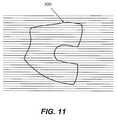
- FIG. 11 depicts a side view of the implant of FIG. 10 , with a modified manufacturing orientation that desirably results in a decreased likelihood of implant failure along a given manufacturing layer (as compared to the example of FIG. 10 ).
- the implant 300 which has been manufactured using a SLM process, incorporates a plurality of horizontal layers (shown as the parallel horizontal lines in the figure, which is a greatly simplified representation of the numerous layers used to create the implant) representing the SLM manufacturing process.
- An FEA or other analysis of the implant which optionally may include material property information particular to the type of manufacturing processes as well as the design and orientation of the implant, may be less likely to identify one or more locations of high stress and/or areas of localized implant weakness that are concurrent with manufacturing layers or other artifacts inherent in the manufacturing processes. In such a case, it may be possible to decrease the local implant thickness in various regions and/or further optimize the orientation of the implant during manufacture to reduce any fracture potential. By incorporating potentially weaker areas of the implant along the longitudinal axis of the condylar portions, the present example may be less likely to fail, or may be designed to fail in less critical regions.
- the use of multiple alignments and/or orientations to create a single implant component is contemplated.
- FEA analysis of a part design and/or orientation identifies multiple regions of potential weakness, and redesign/reorientation of the design prior to SLM manufacture does not sufficiently alleviate strength and/or durability concerns, it may be desirous to reposition and/or reorient the object at one or more times part-way through the manufacturing process (e.g., pausing the layer deposition and laser melting process, moving/rotating the partly finished implant in some manner, and then continuing the layer deposition and laser melting process to complete the implant manufacture) to address localized fracture potential.
- the design and manufacture of an implant component using SLM manufacturing methods may include additional processing and/or finishing steps which are not mandated, required and/or are necessary to prepare the part for use and implantation when the part is manufactured using conventional methods (e.g., casting, wrought and/or machining, etc.).
- additional manufacturing and/or finishing steps which can include coating, filling, remelting, HIP-ping, annealing and/or machining, as well as potentially adding additional material to the implant surface to thereby allow for additional polishing and/or grinding to remove the undesired surface features.
- additional processes to "finish" a SLM part, including the use of such processes on a localize portion of the implant (e.g., performed only on the articulating surfaces or other implant surfaces having undesirable features or characteristics).
- a wide variety of standard finishing techniques used with cast or wrought implants such as polishing, drag finishing, machining and/or bead/grit blasting, may be used to finish SLM parts as well, with varying results.
- Implant components generated by different techniques can be assessed and compared for their accuracy of shape relative to the intended shape design, for their mechanical strength, and for other factors. In this way, different manufacturing techniques can supply another consideration for achieving an implant component design with one or more target features. For example, if accuracy of shape relative to the intended shape design is critical to a particular patient's implant component design, then the manufacturing technique supplying the most accurate shape can be selected. If a minimum implant thickness is critical to a particular patient's implant component design, then the manufacturing technique supplying the highest mechanical strength and therefore allowing the most minimal implant component thickness, can be selected.
- Branner et al. describe a method a method for the design and optimization of additive layer manufacturing through a numerical coupled-field simulation, based on the finite element analysis (FEA). Branner's method can be used for assessing and comparing product mechanical strength generated by different additive layer manufacturing techniques, for example, SLS, SLM, DMLS, and LC.
- FEA finite element analysis
- an implant can include components and/or implant component parts produced via various methods.
- the knee implant can include a metal femoral implant component produced by casting or by an additive manufacturing technique and having a patient-specific femoral intercondylar distance; a tibial component cut from a blank and machined to be patient-specific for the perimeter of the patient's cut tibia; and a tibial insert having a standard lock and a top surface that is patient-specific for at least the patient's intercondylar distance between the tibial insert dishes to accommodate the patient-specific femoral intercondylar distance of the femoral implant.
- a knee implant can include a metal femoral implant component produced by casting or by an additive manufacturing technique that is patient-specific with respect to a particular patient's M-L dimension and standard with respect to the patient's femoral intercondylar distance; a tibial component cut from a blank and machined to be patient-specific for the perimeter of the patient's cut tibia; and a tibial insert having a standard lock and a top surface that includes a standard intercondylar distance between the tibial insert dishes to accommodate the standard femoral intercondylar distance of the femoral implant.
- a tibial tray component can be machined, molded, casted, manufactured through additive techniques such as laser sintering, selective laser melting or electron beam melting or otherwise constructed out of a metal or metal alloy such as cobalt chromium.
- the insert component may be machined, molded, manufactured through rapid prototyping or additive techniques or otherwise constructed out of a plastic polymer such as ultra high molecular weight polyethylene.
- Other known materials, such as ceramics including ceramic coating, may be used as well, for one or both components, or in combination with the metal, metal alloy and polymer described above.
- an implant may be constructed as one piece out of any of the above, or other, materials, or in multiple pieces out of a combination of materials.
- a tray component constructed of a polymer with a two-piece insert component constructed one piece out of a metal alloy and the other piece constructed out of ceramic.
- FIG. 12 depicts a hip stem 325 and a plurality of horizontal layers (shown as the parallel horizontal lines in the figure, which is a greatly simplified representation of the numerous layers used to create the implant) representing the SLM manufacturing process.
- An FEA or other analysis of the implant may identify one or more locations of high stress and/or areas of localized implant weakness.
- One such region that could be prone to fracture and/or failure could be a portion of the implant in the vicinity of region B-B, which includes a region where maximum implant stresses (for example, along the neck 350 of the implant) approximately meets a horizontal layer 355 created during the SLM manufacturing process. In such a case, it may be desirous to increase the local implant thickness proximate this region and/or alter the orientation of the implant during manufacture to reduce the fracture potential along this layer.
- FIG. 13 depicts the same hip stem 325, where rotation of the implant design during manufacture could potentially reduce the potential for such neck fractures due to localized material conditions and/or fracture planes.
- any material known in the art can be used for any of the implant systems and component described in the foregoing examples, for example including, but not limited to metal, metal alloys, combinations of metals, plastic, polyethylene, cross-linked polyethylene's or polymers or plastics, pyrolytic carbon, nanotubes and carbons, as well as biologic materials.
- fixation techniques and combinations thereof known in the art can be used for any of the implant systems and component described in the foregoing examples, for example including, but not limited to cementing techniques, porous coating of at least portions of an implant component, press fit techniques of at least a portion of an implant, ingrowth techniques, etc.
Priority Applications (1)
| Application Number | Priority Date | Filing Date | Title |
|---|---|---|---|
| EP16190665.6A EP3195956A1 (en) | 2012-04-13 | 2013-04-13 | Devices and methods for additive manufacturing of implant components |
Applications Claiming Priority (2)
| Application Number | Priority Date | Filing Date | Title |
|---|---|---|---|
| US201261623776P | 2012-04-13 | 2012-04-13 | |
| PCT/US2013/036505 WO2013155500A1 (en) | 2012-04-13 | 2013-04-13 | Devices and methods for additive manufacturing of implant components |
Related Child Applications (1)
| Application Number | Title | Priority Date | Filing Date |
|---|---|---|---|
| EP16190665.6A Division EP3195956A1 (en) | 2012-04-13 | 2013-04-13 | Devices and methods for additive manufacturing of implant components |
Publications (3)
| Publication Number | Publication Date |
|---|---|
| EP2836168A1 EP2836168A1 (en) | 2015-02-18 |
| EP2836168A4 EP2836168A4 (en) | 2015-04-08 |
| EP2836168B1 true EP2836168B1 (en) | 2016-09-28 |
Family
ID=49328232
Family Applications (2)
| Application Number | Title | Priority Date | Filing Date |
|---|---|---|---|
| EP16190665.6A Withdrawn EP3195956A1 (en) | 2012-04-13 | 2013-04-13 | Devices and methods for additive manufacturing of implant components |
| EP13775348.9A Active EP2836168B1 (en) | 2012-04-13 | 2013-04-13 | Methods for additive manufacturing of implant components |
Family Applications Before (1)
| Application Number | Title | Priority Date | Filing Date |
|---|---|---|---|
| EP16190665.6A Withdrawn EP3195956A1 (en) | 2012-04-13 | 2013-04-13 | Devices and methods for additive manufacturing of implant components |
Country Status (14)
| Country | Link |
|---|---|
| US (1) | US20150093283A1 (ja) |
| EP (2) | EP3195956A1 (ja) |
| JP (1) | JP5973057B2 (ja) |
| CN (1) | CN104363860B (ja) |
| AU (1) | AU2013245697B2 (ja) |
| CA (1) | CA2870017A1 (ja) |
| CR (1) | CR20140512A (ja) |
| HK (1) | HK1206233A1 (ja) |
| MX (1) | MX2014012327A (ja) |
| MY (1) | MY169357A (ja) |
| NZ (1) | NZ700805A (ja) |
| RU (1) | RU2579623C1 (ja) |
| WO (1) | WO2013155500A1 (ja) |
| ZA (1) | ZA201407511B (ja) |
Families Citing this family (104)
| Publication number | Priority date | Publication date | Assignee | Title |
|---|---|---|---|---|
| US8439926B2 (en) | 2001-05-25 | 2013-05-14 | Conformis, Inc. | Patient selectable joint arthroplasty devices and surgical tools |
| EP2591756A1 (en) | 2007-02-14 | 2013-05-15 | Conformis, Inc. | Implant device and method for manufacture |
| EP2194879B1 (en) | 2007-08-17 | 2020-05-13 | Zimmer, Inc. | Implant design analysis suite |
| FR2932674B1 (fr) | 2008-06-20 | 2011-11-18 | Tornier Sa | Procede de modelisation d'une surface glenoidienne d'une omoplate, dispositif d'implantation d'un composant glenoidien d'une prothese d'epaule, et procede de fabrication d'un tel compose. |
| US9078755B2 (en) | 2009-02-25 | 2015-07-14 | Zimmer, Inc. | Ethnic-specific orthopaedic implants and custom cutting jigs |
| CN102438559B (zh) | 2009-02-25 | 2015-03-25 | 捷迈有限公司 | 智能软骨系统 |
| CA2778057C (en) | 2009-10-29 | 2019-02-19 | Zimmer, Inc. | Patient-specific mill guide |
| EP2389901B8 (en) | 2010-05-24 | 2013-05-15 | Episurf IP Management AB | An implant for cartilage repair |
| WO2012058344A1 (en) | 2010-10-29 | 2012-05-03 | The Cleveland Clinic Foundation | System for assisting with attachment of a stock implant to a patient tissue |
| WO2012058355A1 (en) | 2010-10-29 | 2012-05-03 | The Cleveland Clinic Foundation | System of preoperative planning and provision of patient-specific surgical aids |
| WO2012058349A2 (en) | 2010-10-29 | 2012-05-03 | The Cleveland Clinic Foundation | System and method for association of a guiding aid with a patient tissue |
| EP2632383B1 (en) | 2010-10-29 | 2022-02-23 | The Cleveland Clinic Foundation | System for assisting with arrangement of a stock instrument with respect to a patient tissue |
| EP2709540B1 (en) | 2011-05-11 | 2020-11-04 | The Cleveland Clinic Foundation | Generating patient specific instruments for use as surgical aids |
| US8992539B2 (en) | 2011-05-19 | 2015-03-31 | The Cleveland Clinic Foundation | Apparatus and method for providing a reference indication to a patient tissue |
| US9408686B1 (en) | 2012-01-20 | 2016-08-09 | Conformis, Inc. | Devices, systems and methods for manufacturing orthopedic implants |
| US10325065B2 (en) | 2012-01-24 | 2019-06-18 | Zimmer, Inc. | Method and system for creating patient-specific instrumentation for chondral graft transfer |
| JP6166775B2 (ja) | 2012-03-28 | 2017-07-19 | オーソソフト インコーポレイティド | 患者特有の器具を使用した関節窩インプラント術 |
| WO2013167903A1 (en) | 2012-05-10 | 2013-11-14 | Renishaw Plc | Method of manufacturing an article |
| ES2901925T3 (es) | 2012-05-10 | 2022-03-24 | Renishaw Plc | Método de fabricación de un artículo |
| GB201210120D0 (en) * | 2012-05-10 | 2012-07-25 | Renishaw Plc | Laser sintered part and method of manufacture |
| CA2871950C (en) | 2012-05-24 | 2020-08-25 | Zimmer, Inc. | Patient-specific instrumentation and method for articular joint repair |
| US10271886B2 (en) | 2012-07-23 | 2019-04-30 | Zimmer, Inc. | Patient-specific instrumentation for implant revision surgery |
| AU2013296108B2 (en) | 2012-07-24 | 2017-08-31 | Orthosoft Ulc | Patient specific instrumentation with mems in surgery |
| US9636229B2 (en) | 2012-09-20 | 2017-05-02 | Conformis, Inc. | Solid freeform fabrication of implant components |
| JP2015532858A (ja) | 2012-09-21 | 2015-11-16 | コンフォーミス・インコーポレイテッドConforMIS, Inc. | 固体自由造形製造を使用してインプラント構成要素の設計および製造を最適化するための方法およびシステム |
| US9987148B2 (en) | 2013-06-11 | 2018-06-05 | Orthosoft Inc. | Acetabular cup prosthesis positioning instrument and method |
| EP3007641B1 (en) | 2013-06-11 | 2020-08-26 | Orthosoft ULC | Computer assisted subchondral injection |
| GB201310762D0 (en) * | 2013-06-17 | 2013-07-31 | Rolls Royce Plc | An additive layer manufacturing method |
| US9776364B2 (en) * | 2013-08-09 | 2017-10-03 | Apple Inc. | Method for instructing a 3D printing system comprising a 3D printer and 3D printing system |
| EP3035891B1 (en) | 2013-08-21 | 2020-05-27 | Laboratoires Bodycad Inc. | Anatomically adapted orthopedic implant |
| EP3035872B1 (en) | 2013-08-21 | 2018-03-07 | Laboratoires Bodycad Inc. | Bone resection guide and method of manufacture |
| CN105705117B (zh) | 2013-09-25 | 2018-07-24 | 捷迈有限公司 | 用于矫形手术的患者特定器械(psi)以及利用x射线来制作其的系统和方法 |
| WO2015058182A1 (en) * | 2013-10-18 | 2015-04-23 | +Mfg, LLC | Method and apparatus for fabrication of articles by molten and semi-molten deposition |
| WO2015071757A1 (en) | 2013-11-13 | 2015-05-21 | Tornier Sas | Shoulder patient specific instrument |
| GB2521386A (en) * | 2013-12-18 | 2015-06-24 | Ibm | Improvements in 3D printing |
| WO2015157703A2 (en) * | 2014-04-11 | 2015-10-15 | Smith & Nephew, Inc. | Dmls orthopedic intramedullary device and method of manufacture |
| US10350022B2 (en) | 2014-04-30 | 2019-07-16 | Zimmer, Inc. | Acetabular cup impacting using patient-specific instrumentation |
| US10217530B2 (en) | 2014-06-03 | 2019-02-26 | Zimmer, Inc. | Patient-specific cutting block and method of manufacturing same |
| US10687956B2 (en) | 2014-06-17 | 2020-06-23 | Titan Spine, Inc. | Corpectomy implants with roughened bioactive lateral surfaces |
| EP4212113A1 (en) | 2014-06-25 | 2023-07-19 | Canary Medical Switzerland AG | Devices monitoring spinal implants |
| EP3751574A3 (en) | 2014-06-25 | 2021-04-21 | Canary Medical Inc. | Devices, systems and methods for using and monitoring orthopedic hardware |
| CA2959490A1 (en) * | 2014-09-19 | 2016-03-24 | Moog Inc. | Method for layer-by-layer removal of defects during additive manufacturing |
| US10028841B2 (en) | 2015-01-27 | 2018-07-24 | K2M, Inc. | Interbody spacer |
| AU2016200443B2 (en) | 2015-01-27 | 2020-09-10 | K2M, Inc. | Spinal implant |
| US10405928B2 (en) | 2015-02-02 | 2019-09-10 | Orthosoft Ulc | Acetabulum rim digitizer device and method |
| US10913202B2 (en) * | 2015-03-19 | 2021-02-09 | The Board Of Regents, The University Of Texas System | Structurally integrating metal objects into additive manufactured structures |
| EP3273893B1 (en) | 2015-03-25 | 2023-03-01 | Orthosoft ULC | Method and system for assisting implant placement in thin bones such as scapula |
| CN107924709B (zh) | 2015-05-28 | 2022-05-17 | 捷迈有限公司 | 患者特异性骨移植系统和方法 |
| US10582969B2 (en) | 2015-07-08 | 2020-03-10 | Zimmer, Inc. | Patient-specific instrumentation for implant revision surgery |
| WO2017015146A2 (en) * | 2015-07-17 | 2017-01-26 | Applied Materials, Inc. | Brace structures for additive manufacturing |
| DE102015112918A1 (de) * | 2015-08-06 | 2017-02-09 | Cl Schutzrechtsverwaltungs Gmbh | Verfahren zur Herstellung eines dreidimensionalen Objekts |
| GB201514801D0 (en) | 2015-08-20 | 2015-10-07 | Rolls Royce Plc And Rolls Royce Deutschland Ltd & Co Kg | Method of manufacture of a turbine component |
| US10874408B2 (en) | 2015-09-30 | 2020-12-29 | Zimmer, Inc | Patient-specific instrumentation for patellar resurfacing surgery and method |
| US10983504B2 (en) | 2015-09-30 | 2021-04-20 | Renishaw Plc | Control of a chain of machines, including an additive manufacturing machine, in the manufacture of a workpiece |
| US10413998B2 (en) * | 2015-10-02 | 2019-09-17 | Caterpillar Inc. | Laser sintering of intricate parts |
| JP6914266B2 (ja) | 2015-11-20 | 2021-08-04 | タイタン スパイン インコーポレイテッドTitan Spine,Inc. | 整形外科インプラントを付加製作するための方法 |
| TWI726940B (zh) | 2015-11-20 | 2021-05-11 | 美商泰坦脊柱股份有限公司 | 積層製造整形外科植入物之方法 |
| US10624764B2 (en) | 2015-11-26 | 2020-04-21 | Orthosoft Ulc | System and method for the registration of an anatomical feature |
| AU2016371425B2 (en) | 2015-12-16 | 2021-09-02 | Howmedica Osteonics Corp. | Patient specific instruments and methods for joint prosthesis |
| US10906291B2 (en) * | 2016-01-06 | 2021-02-02 | Autodesk, Inc. | Controllable release build plate for 3D printer |
| US10391753B2 (en) * | 2016-02-11 | 2019-08-27 | General Electric Company | Methods and keyway supports for additive manufacturing |
| US10549478B2 (en) * | 2016-02-11 | 2020-02-04 | General Electric Company | Methods and surrounding supports for additive manufacturing |
| JP2019510656A (ja) * | 2016-03-17 | 2019-04-18 | シーメンス アクティエンゲゼルシャフト | 付加製造される部品の方位を決定する方法、およびコンピュータ可読媒体 |
| FR3049453B1 (fr) * | 2016-03-30 | 2018-04-27 | Medicrea International | Procede de fabrication d'un implant, notamment vertebral ou intervertebral, et implant obtenu par ce procede |
| US20170282454A1 (en) * | 2016-04-04 | 2017-10-05 | Rolls-Royce Plc | Method of manufacture of a component |
| CN105853026A (zh) * | 2016-04-28 | 2016-08-17 | 华南理工大学 | 一种个性化股骨假体及制造方法 |
| US20200000595A1 (en) | 2016-06-07 | 2020-01-02 | HD LifeSciences LLC | High X-Ray Lucency Lattice Structures |
| JP2019523092A (ja) * | 2016-08-03 | 2019-08-22 | タイタン スパイン インコーポレイテッドTitan Spine,Inc. | αケースがなく、かつ骨誘導が増強されたチタンインプラント表面 |
| HK1224885A (ja) * | 2016-09-08 | 2017-08-25 | ||
| US10070959B2 (en) * | 2016-09-28 | 2018-09-11 | DePuy Synthes Products, Inc. | Method of texturing prosthetic implants |
| USD808524S1 (en) | 2016-11-29 | 2018-01-23 | Laboratoires Bodycad Inc. | Femoral implant |
| WO2018100250A1 (fr) * | 2016-11-30 | 2018-06-07 | Abdelmadjid Djemai | Implant dentaire et element de fixation autobloquant a structures poreuses heterogenes et son procede de fabrication |
| US10731565B2 (en) | 2016-12-20 | 2020-08-04 | General Electric Company | Additive manufactured object with self-breaking support with fluid passage |
| US20180228570A1 (en) | 2017-02-14 | 2018-08-16 | HD LifeSciences LLC | Variably X-Ray Lucent Marker System |
| US10905436B2 (en) | 2017-03-02 | 2021-02-02 | Optimotion Implants, Llc | Knee arthroplasty systems and methods |
| US11406502B2 (en) | 2017-03-02 | 2022-08-09 | Optimotion Implants LLC | Orthopedic implants and methods |
| WO2018182834A1 (en) | 2017-04-01 | 2018-10-04 | HD LifeSciences LLC | Three-dimensional lattice structures for implants |
| AU2018203667B2 (en) | 2017-05-25 | 2022-09-29 | Stryker European Operations Holdings Llc | Fusion cage with integrated fixation and insertion features |
| US11407034B2 (en) | 2017-07-06 | 2022-08-09 | OmniTek Technology Ltda. | Selective laser melting system and method of using same |
| US11006981B2 (en) | 2017-07-07 | 2021-05-18 | K2M, Inc. | Surgical implant and methods of additive manufacturing |
| US20190015923A1 (en) * | 2017-07-11 | 2019-01-17 | United Technologies Corporation | Additively manufactured article including electrically removable supports |
| WO2019014281A1 (en) | 2017-07-11 | 2019-01-17 | Tornier, Inc. | HUMERAL CUTTING GUIDES SPECIFIC TO A PATIENT |
| US11166733B2 (en) | 2017-07-11 | 2021-11-09 | Howmedica Osteonics Corp. | Guides and instruments for improving accuracy of glenoid implant placement |
| DE102017212182A1 (de) * | 2017-07-17 | 2019-01-17 | Trumpf Laser- Und Systemtechnik Gmbh | Verfahren zum Herstellen mindestens eines Teils aus Edelmetall und/oder biokompatiblem Werkstoff |
| WO2019023476A1 (en) | 2017-07-26 | 2019-01-31 | Optimotion Implants LLC | MODULAR KNEE PROSTHESIS, INSTRUMENTS, AND ASSOCIATED METHODS |
| US11576725B2 (en) | 2017-12-12 | 2023-02-14 | Orthosoft Ulc | Patient-specific instrumentation for implant revision surgery |
| US10864602B2 (en) * | 2018-02-06 | 2020-12-15 | Warsaw Orthopedic, Inc. | System and method of manufacture for spinal implant |
| WO2019168516A1 (en) | 2018-02-28 | 2019-09-06 | Hewlett-Packard Development Company, L.P. | Three-dimensional printing |
| SE543241C2 (en) | 2018-04-27 | 2020-10-27 | Episurf Ip Man Ab | An implant for cartilage and / or bone repair |
| US11117329B2 (en) | 2018-06-26 | 2021-09-14 | General Electric Company | Additively manufactured build assemblies having reduced distortion and residual stress |
| WO2020023938A1 (en) | 2018-07-26 | 2020-01-30 | HD LifeSciences LLC | Dynamic implant fixation plate |
| US11167375B2 (en) | 2018-08-10 | 2021-11-09 | The Research Foundation For The State University Of New York | Additive manufacturing processes and additively manufactured products |
| CA3108562A1 (en) * | 2018-08-18 | 2020-02-27 | University Of Saskatchewan | Implant for bone fracture stabilization |
| US11179895B2 (en) * | 2018-10-05 | 2021-11-23 | Raytheon Technologies Corporation | Kinetic disassembly of support structure system for additively manufactured rotating components |
| IT201800010188A1 (it) * | 2018-11-09 | 2020-05-09 | Adler Ortho S P A | Stelo per protesi di anca, con collo fisso o modulare. |
| US10668664B1 (en) | 2018-11-09 | 2020-06-02 | Thermwood Corporation | Systems and methods for printing components using additive manufacturing |
| US11497617B2 (en) | 2019-01-16 | 2022-11-15 | Nanohive Medical Llc | Variable depth implants |
| US11440097B2 (en) | 2019-02-12 | 2022-09-13 | General Electric Company | Methods for additively manufacturing components using lattice support structures |
| US11213403B2 (en) | 2019-03-14 | 2022-01-04 | Medos International Sarl | Devices and methods for optimized spinal fixation |
| EP3718729B1 (de) * | 2019-04-02 | 2023-10-04 | OWL AM Additive Manufacturing GmbH | Fertigungsverfahren mit additiver bauteilherstellung und nachbearbeitung |
| US20210394451A1 (en) * | 2020-06-23 | 2021-12-23 | Continuous Composites Inc. | Systems and methods for controlling additive manufacturing |
| US11844697B2 (en) | 2020-09-03 | 2023-12-19 | Globus Medical, Inc. | Systems and methods for knee arthroplasty |
| US11730603B2 (en) | 2020-09-03 | 2023-08-22 | Globus Medical, Inc. | Systems and methods for knee arthroplasty |
| DE102021213351A1 (de) | 2021-11-26 | 2023-06-01 | Aesculap Ag | Verfahren zum Herstellen eines Medizinprodukts und Medizinprodukt |
Family Cites Families (17)
| Publication number | Priority date | Publication date | Assignee | Title |
|---|---|---|---|---|
| RU2110233C1 (ru) * | 1993-07-05 | 1998-05-10 | Российский научно-исследовательский институт травматологии и ортопедии им.Р.Р.Вредена | Эндопротез коленного сустава и способ изготовления керамического эндопротеза коленного сустава |
| JP3398481B2 (ja) * | 1994-07-19 | 2003-04-21 | 帝人製機株式会社 | 光造形法におけるサポート形成方法 |
| JP3155185B2 (ja) * | 1995-12-20 | 2001-04-09 | 松下電工株式会社 | 三次元形状造形物の製造方法 |
| RU2121319C1 (ru) * | 1997-08-14 | 1998-11-10 | Акционерное общество открытого типа "Санкт-Петербургский институт огнеупоров" | Эндопротез коленного сустава |
| DE10220591B4 (de) * | 2002-05-08 | 2004-03-18 | Mathys Medizinaltechnik Ag | Gelenkprothese mit Zwischenelement mit unterschiedlichen Krümmungsradien |
| JP4148316B2 (ja) * | 2002-11-18 | 2008-09-10 | 株式会社神戸製鋼所 | 人工膝関節 |
| US8292967B2 (en) * | 2005-04-21 | 2012-10-23 | Biomet Manufacturing Corp. | Method and apparatus for use of porous implants |
| US8728387B2 (en) * | 2005-12-06 | 2014-05-20 | Howmedica Osteonics Corp. | Laser-produced porous surface |
| EP1803513B1 (en) * | 2005-12-30 | 2017-03-29 | Howmedica Osteonics Corp. | Method of manufacturing implants using laser |
| US8407067B2 (en) * | 2007-04-17 | 2013-03-26 | Biomet Manufacturing Corp. | Method and apparatus for manufacturing an implant |
| RU2355324C2 (ru) * | 2007-07-16 | 2009-05-20 | ФГУ "Российский научно-исследовательский институт травматологии и ортопедии им. Р.Р. Вредена Федерального агентства по высокотехнологичной медицинской помощи" (ФГУ "РНИИТО им. Р.Р. Вредена Росмедтехнологий") | Способ замещения обширных дефектов мыщелков бедренной и большеберцовой костей при ревизионном эндопротезировании коленного сустава |
| EP2481555B1 (en) * | 2007-09-17 | 2021-08-25 | 3D Systems, Inc. | Region-based supports for parts produced by solid freeform fabrication |
| WO2009111626A2 (en) * | 2008-03-05 | 2009-09-11 | Conformis, Inc. | Implants for altering wear patterns of articular surfaces |
| AU2009246474B2 (en) * | 2008-05-12 | 2015-04-16 | Conformis, Inc. | Devices and methods for treatment of facet and other joints |
| US20100217270A1 (en) * | 2009-02-25 | 2010-08-26 | Conformis, Inc. | Integrated Production of Patient-Specific Implants and Instrumentation |
| EP2289462B1 (de) * | 2009-08-25 | 2012-05-30 | BEGO Medical GmbH | Vorrichtung und Verfahren zur kontinuierlichen, generativen Fertigung |
| WO2011056995A2 (en) * | 2009-11-04 | 2011-05-12 | Conformis, Inc. | Patient-adapted and improved orthopedic implants, designs and related tools |
-
2013
- 2013-04-13 MY MYPI2014702957A patent/MY169357A/en unknown
- 2013-04-13 CA CA2870017A patent/CA2870017A1/en not_active Abandoned
- 2013-04-13 EP EP16190665.6A patent/EP3195956A1/en not_active Withdrawn
- 2013-04-13 US US14/390,829 patent/US20150093283A1/en not_active Abandoned
- 2013-04-13 MX MX2014012327A patent/MX2014012327A/es unknown
- 2013-04-13 JP JP2015505970A patent/JP5973057B2/ja active Active
- 2013-04-13 EP EP13775348.9A patent/EP2836168B1/en active Active
- 2013-04-13 AU AU2013245697A patent/AU2013245697B2/en active Active
- 2013-04-13 CN CN201380031091.9A patent/CN104363860B/zh active Active
- 2013-04-13 NZ NZ700805A patent/NZ700805A/en unknown
- 2013-04-13 RU RU2014141567/14A patent/RU2579623C1/ru not_active IP Right Cessation
- 2013-04-13 WO PCT/US2013/036505 patent/WO2013155500A1/en active Application Filing
-
2014
- 2014-10-16 ZA ZA2014/07511A patent/ZA201407511B/en unknown
- 2014-11-07 CR CR20140512A patent/CR20140512A/es unknown
-
2015
- 2015-07-17 HK HK15106843.9A patent/HK1206233A1/zh unknown
Also Published As
| Publication number | Publication date |
|---|---|
| RU2579623C1 (ru) | 2016-04-10 |
| US20150093283A1 (en) | 2015-04-02 |
| EP2836168A1 (en) | 2015-02-18 |
| EP2836168A4 (en) | 2015-04-08 |
| AU2013245697B2 (en) | 2017-10-26 |
| CN104363860A (zh) | 2015-02-18 |
| JP5973057B2 (ja) | 2016-08-23 |
| EP3195956A1 (en) | 2017-07-26 |
| MX2014012327A (es) | 2015-05-12 |
| ZA201407511B (en) | 2016-01-27 |
| WO2013155500A1 (en) | 2013-10-17 |
| HK1206233A1 (zh) | 2016-01-08 |
| AU2013245697A1 (en) | 2014-10-30 |
| NZ700805A (en) | 2016-09-30 |
| CA2870017A1 (en) | 2013-10-17 |
| MY169357A (en) | 2019-03-26 |
| CR20140512A (es) | 2015-03-25 |
| CN104363860B (zh) | 2016-04-13 |
| JP2015512762A (ja) | 2015-04-30 |
Similar Documents
| Publication | Publication Date | Title |
|---|---|---|
| EP2836168B1 (en) | Methods for additive manufacturing of implant components | |
| US10485676B2 (en) | Solid freeform fabrication of implant components | |
| US9849019B2 (en) | Methods and systems for optimizing design and manufacture of implant components using solid freeform fabrication | |
| US9517134B2 (en) | Implant device and method for manufacture | |
| EP2114312B1 (en) | Method for manufacture of an implant device | |
| EP2496183B1 (en) | Patient-adapted and improved orthopedic implants, designs and related tools | |
| US20140259629A1 (en) | Devices, methods and systems for forming implant components | |
| AU2012217654B2 (en) | Patient-adapted and improved articular implants, procedures and tools to address, assess, correct, modify and/or accommodate anatomical variation and/or asymmetry | |
| US20150032215A1 (en) | Patient-Adapted Posterior Stabilized Knee Implants, Designs and Related Methods and Tools | |
| WO2016044352A1 (en) | 3d printing surgical repair systems | |
| Mihalko | Additive manufacturing of arthroplasty implants | |
| US9827104B2 (en) | Method of machining a workpiece into a desired patient specific object | |
| Judkins et al. | Medical Applications of Additive Manufacturing |
Legal Events
| Date | Code | Title | Description |
|---|---|---|---|
| PUAI | Public reference made under article 153(3) epc to a published international application that has entered the european phase |
Free format text: ORIGINAL CODE: 0009012 |
|
| 17P | Request for examination filed |
Effective date: 20141112 |
|
| AK | Designated contracting states |
Kind code of ref document: A1 Designated state(s): AL AT BE BG CH CY CZ DE DK EE ES FI FR GB GR HR HU IE IS IT LI LT LU LV MC MK MT NL NO PL PT RO RS SE SI SK SM TR |
|
| AX | Request for extension of the european patent |
Extension state: BA ME |
|
| RA4 | Supplementary search report drawn up and despatched (corrected) |
Effective date: 20150310 |
|
| RIC1 | Information provided on ipc code assigned before grant |
Ipc: A61F 2/28 20060101ALI20150304BHEP Ipc: A61F 2/30 20060101ALI20150304BHEP Ipc: A61F 2/38 20060101AFI20150304BHEP |
|
| DAX | Request for extension of the european patent (deleted) | ||
| 17Q | First examination report despatched |
Effective date: 20151026 |
|
| REG | Reference to a national code |
Ref country code: HK Ref legal event code: DE Ref document number: 1206233 Country of ref document: HK |
|
| GRAP | Despatch of communication of intention to grant a patent |
Free format text: ORIGINAL CODE: EPIDOSNIGR1 |
|
| INTG | Intention to grant announced |
Effective date: 20160506 |
|
| GRAS | Grant fee paid |
Free format text: ORIGINAL CODE: EPIDOSNIGR3 |
|
| GRAA | (expected) grant |
Free format text: ORIGINAL CODE: 0009210 |
|
| AK | Designated contracting states |
Kind code of ref document: B1 Designated state(s): AL AT BE BG CH CY CZ DE DK EE ES FI FR GB GR HR HU IE IS IT LI LT LU LV MC MK MT NL NO PL PT RO RS SE SI SK SM TR |
|
| REG | Reference to a national code |
Ref country code: GB Ref legal event code: FG4D |
|
| REG | Reference to a national code |
Ref country code: CH Ref legal event code: EP |
|
| REG | Reference to a national code |
Ref country code: AT Ref legal event code: REF Ref document number: 832094 Country of ref document: AT Kind code of ref document: T Effective date: 20161015 |
|
| REG | Reference to a national code |
Ref country code: IE Ref legal event code: FG4D |
|
| REG | Reference to a national code |
Ref country code: DE Ref legal event code: R096 Ref document number: 602013012237 Country of ref document: DE |
|
| REG | Reference to a national code |
Ref country code: LT Ref legal event code: MG4D |
|
| PG25 | Lapsed in a contracting state [announced via postgrant information from national office to epo] |
Ref country code: LT Free format text: LAPSE BECAUSE OF FAILURE TO SUBMIT A TRANSLATION OF THE DESCRIPTION OR TO PAY THE FEE WITHIN THE PRESCRIBED TIME-LIMIT Effective date: 20160928 Ref country code: NO Free format text: LAPSE BECAUSE OF FAILURE TO SUBMIT A TRANSLATION OF THE DESCRIPTION OR TO PAY THE FEE WITHIN THE PRESCRIBED TIME-LIMIT Effective date: 20161228 Ref country code: HR Free format text: LAPSE BECAUSE OF FAILURE TO SUBMIT A TRANSLATION OF THE DESCRIPTION OR TO PAY THE FEE WITHIN THE PRESCRIBED TIME-LIMIT Effective date: 20160928 Ref country code: FI Free format text: LAPSE BECAUSE OF FAILURE TO SUBMIT A TRANSLATION OF THE DESCRIPTION OR TO PAY THE FEE WITHIN THE PRESCRIBED TIME-LIMIT Effective date: 20160928 Ref country code: RS Free format text: LAPSE BECAUSE OF FAILURE TO SUBMIT A TRANSLATION OF THE DESCRIPTION OR TO PAY THE FEE WITHIN THE PRESCRIBED TIME-LIMIT Effective date: 20160928 |
|
| REG | Reference to a national code |
Ref country code: NL Ref legal event code: MP Effective date: 20160928 |
|
| REG | Reference to a national code |
Ref country code: SE Ref legal event code: TRGR |
|
| REG | Reference to a national code |
Ref country code: AT Ref legal event code: MK05 Ref document number: 832094 Country of ref document: AT Kind code of ref document: T Effective date: 20160928 |
|
| PG25 | Lapsed in a contracting state [announced via postgrant information from national office to epo] |
Ref country code: LV Free format text: LAPSE BECAUSE OF FAILURE TO SUBMIT A TRANSLATION OF THE DESCRIPTION OR TO PAY THE FEE WITHIN THE PRESCRIBED TIME-LIMIT Effective date: 20160928 Ref country code: NL Free format text: LAPSE BECAUSE OF FAILURE TO SUBMIT A TRANSLATION OF THE DESCRIPTION OR TO PAY THE FEE WITHIN THE PRESCRIBED TIME-LIMIT Effective date: 20160928 Ref country code: GR Free format text: LAPSE BECAUSE OF FAILURE TO SUBMIT A TRANSLATION OF THE DESCRIPTION OR TO PAY THE FEE WITHIN THE PRESCRIBED TIME-LIMIT Effective date: 20161229 Ref country code: SE Free format text: LAPSE BECAUSE OF FAILURE TO SUBMIT A TRANSLATION OF THE DESCRIPTION OR TO PAY THE FEE WITHIN THE PRESCRIBED TIME-LIMIT Effective date: 20160928 |
|
| REG | Reference to a national code |
Ref country code: FR Ref legal event code: PLFP Year of fee payment: 5 |
|
| PG25 | Lapsed in a contracting state [announced via postgrant information from national office to epo] |
Ref country code: EE Free format text: LAPSE BECAUSE OF FAILURE TO SUBMIT A TRANSLATION OF THE DESCRIPTION OR TO PAY THE FEE WITHIN THE PRESCRIBED TIME-LIMIT Effective date: 20160928 Ref country code: RO Free format text: LAPSE BECAUSE OF FAILURE TO SUBMIT A TRANSLATION OF THE DESCRIPTION OR TO PAY THE FEE WITHIN THE PRESCRIBED TIME-LIMIT Effective date: 20160928 |
|
| PG25 | Lapsed in a contracting state [announced via postgrant information from national office to epo] |
Ref country code: BG Free format text: LAPSE BECAUSE OF FAILURE TO SUBMIT A TRANSLATION OF THE DESCRIPTION OR TO PAY THE FEE WITHIN THE PRESCRIBED TIME-LIMIT Effective date: 20161228 Ref country code: CZ Free format text: LAPSE BECAUSE OF FAILURE TO SUBMIT A TRANSLATION OF THE DESCRIPTION OR TO PAY THE FEE WITHIN THE PRESCRIBED TIME-LIMIT Effective date: 20160928 Ref country code: ES Free format text: LAPSE BECAUSE OF FAILURE TO SUBMIT A TRANSLATION OF THE DESCRIPTION OR TO PAY THE FEE WITHIN THE PRESCRIBED TIME-LIMIT Effective date: 20160928 Ref country code: BE Free format text: LAPSE BECAUSE OF FAILURE TO SUBMIT A TRANSLATION OF THE DESCRIPTION OR TO PAY THE FEE WITHIN THE PRESCRIBED TIME-LIMIT Effective date: 20160928 Ref country code: SM Free format text: LAPSE BECAUSE OF FAILURE TO SUBMIT A TRANSLATION OF THE DESCRIPTION OR TO PAY THE FEE WITHIN THE PRESCRIBED TIME-LIMIT Effective date: 20160928 Ref country code: PL Free format text: LAPSE BECAUSE OF FAILURE TO SUBMIT A TRANSLATION OF THE DESCRIPTION OR TO PAY THE FEE WITHIN THE PRESCRIBED TIME-LIMIT Effective date: 20160928 Ref country code: AT Free format text: LAPSE BECAUSE OF FAILURE TO SUBMIT A TRANSLATION OF THE DESCRIPTION OR TO PAY THE FEE WITHIN THE PRESCRIBED TIME-LIMIT Effective date: 20160928 Ref country code: IS Free format text: LAPSE BECAUSE OF FAILURE TO SUBMIT A TRANSLATION OF THE DESCRIPTION OR TO PAY THE FEE WITHIN THE PRESCRIBED TIME-LIMIT Effective date: 20170128 Ref country code: SK Free format text: LAPSE BECAUSE OF FAILURE TO SUBMIT A TRANSLATION OF THE DESCRIPTION OR TO PAY THE FEE WITHIN THE PRESCRIBED TIME-LIMIT Effective date: 20160928 Ref country code: PT Free format text: LAPSE BECAUSE OF FAILURE TO SUBMIT A TRANSLATION OF THE DESCRIPTION OR TO PAY THE FEE WITHIN THE PRESCRIBED TIME-LIMIT Effective date: 20170130 |
|
| REG | Reference to a national code |
Ref country code: DE Ref legal event code: R097 Ref document number: 602013012237 Country of ref document: DE |
|
| PG25 | Lapsed in a contracting state [announced via postgrant information from national office to epo] |
Ref country code: IT Free format text: LAPSE BECAUSE OF FAILURE TO SUBMIT A TRANSLATION OF THE DESCRIPTION OR TO PAY THE FEE WITHIN THE PRESCRIBED TIME-LIMIT Effective date: 20160928 |
|
| PG25 | Lapsed in a contracting state [announced via postgrant information from national office to epo] |
Ref country code: DK Free format text: LAPSE BECAUSE OF FAILURE TO SUBMIT A TRANSLATION OF THE DESCRIPTION OR TO PAY THE FEE WITHIN THE PRESCRIBED TIME-LIMIT Effective date: 20160928 |
|
| PLBE | No opposition filed within time limit |
Free format text: ORIGINAL CODE: 0009261 |
|
| STAA | Information on the status of an ep patent application or granted ep patent |
Free format text: STATUS: NO OPPOSITION FILED WITHIN TIME LIMIT |
|
| 26N | No opposition filed |
Effective date: 20170629 |
|
| PG25 | Lapsed in a contracting state [announced via postgrant information from national office to epo] |
Ref country code: SI Free format text: LAPSE BECAUSE OF FAILURE TO SUBMIT A TRANSLATION OF THE DESCRIPTION OR TO PAY THE FEE WITHIN THE PRESCRIBED TIME-LIMIT Effective date: 20160928 |
|
| REG | Reference to a national code |
Ref country code: CH Ref legal event code: PL |
|
| REG | Reference to a national code |
Ref country code: HK Ref legal event code: GR Ref document number: 1206233 Country of ref document: HK |
|
| REG | Reference to a national code |
Ref country code: IE Ref legal event code: MM4A |
|
| PG25 | Lapsed in a contracting state [announced via postgrant information from national office to epo] |
Ref country code: MC Free format text: LAPSE BECAUSE OF FAILURE TO SUBMIT A TRANSLATION OF THE DESCRIPTION OR TO PAY THE FEE WITHIN THE PRESCRIBED TIME-LIMIT Effective date: 20160928 |
|
| PG25 | Lapsed in a contracting state [announced via postgrant information from national office to epo] |
Ref country code: LI Free format text: LAPSE BECAUSE OF NON-PAYMENT OF DUE FEES Effective date: 20170430 Ref country code: CH Free format text: LAPSE BECAUSE OF NON-PAYMENT OF DUE FEES Effective date: 20170430 Ref country code: LU Free format text: LAPSE BECAUSE OF NON-PAYMENT OF DUE FEES Effective date: 20170413 |
|
| REG | Reference to a national code |
Ref country code: FR Ref legal event code: PLFP Year of fee payment: 6 |
|
| PG25 | Lapsed in a contracting state [announced via postgrant information from national office to epo] |
Ref country code: IE Free format text: LAPSE BECAUSE OF NON-PAYMENT OF DUE FEES Effective date: 20170413 |
|
| REG | Reference to a national code |
Ref country code: DE Ref legal event code: R082 Ref document number: 602013012237 Country of ref document: DE Representative=s name: GRUND INTELLECTUAL PROPERTY GROUP PATENTANWALT, DE Ref country code: DE Ref legal event code: R081 Ref document number: 602013012237 Country of ref document: DE Owner name: CONFORMIS, INC., BILLERICA, US Free format text: FORMER OWNER: CONFORMIS, INC., BEDFORD, MASS., US |
|
| PG25 | Lapsed in a contracting state [announced via postgrant information from national office to epo] |
Ref country code: MT Free format text: LAPSE BECAUSE OF NON-PAYMENT OF DUE FEES Effective date: 20170413 |
|
| PG25 | Lapsed in a contracting state [announced via postgrant information from national office to epo] |
Ref country code: AL Free format text: LAPSE BECAUSE OF FAILURE TO SUBMIT A TRANSLATION OF THE DESCRIPTION OR TO PAY THE FEE WITHIN THE PRESCRIBED TIME-LIMIT Effective date: 20160928 |
|
| PG25 | Lapsed in a contracting state [announced via postgrant information from national office to epo] |
Ref country code: HU Free format text: LAPSE BECAUSE OF FAILURE TO SUBMIT A TRANSLATION OF THE DESCRIPTION OR TO PAY THE FEE WITHIN THE PRESCRIBED TIME-LIMIT; INVALID AB INITIO Effective date: 20130413 |
|
| REG | Reference to a national code |
Ref country code: GB Ref legal event code: 732E Free format text: REGISTERED BETWEEN 20190620 AND 20190626 |
|
| PG25 | Lapsed in a contracting state [announced via postgrant information from national office to epo] |
Ref country code: CY Free format text: LAPSE BECAUSE OF FAILURE TO SUBMIT A TRANSLATION OF THE DESCRIPTION OR TO PAY THE FEE WITHIN THE PRESCRIBED TIME-LIMIT Effective date: 20160928 |
|
| PG25 | Lapsed in a contracting state [announced via postgrant information from national office to epo] |
Ref country code: MK Free format text: LAPSE BECAUSE OF FAILURE TO SUBMIT A TRANSLATION OF THE DESCRIPTION OR TO PAY THE FEE WITHIN THE PRESCRIBED TIME-LIMIT Effective date: 20160928 |
|
| PG25 | Lapsed in a contracting state [announced via postgrant information from national office to epo] |
Ref country code: TR Free format text: LAPSE BECAUSE OF FAILURE TO SUBMIT A TRANSLATION OF THE DESCRIPTION OR TO PAY THE FEE WITHIN THE PRESCRIBED TIME-LIMIT Effective date: 20160928 |
|
| PGFP | Annual fee paid to national office [announced via postgrant information from national office to epo] |
Ref country code: FR Payment date: 20230530 Year of fee payment: 11 Ref country code: DE Payment date: 20230524 Year of fee payment: 11 |
|
| PGFP | Annual fee paid to national office [announced via postgrant information from national office to epo] |
Ref country code: SE Payment date: 20230530 Year of fee payment: 11 |
|
| PGFP | Annual fee paid to national office [announced via postgrant information from national office to epo] |
Ref country code: GB Payment date: 20230530 Year of fee payment: 11 |