EP2835920B1 - Method and device for aggregating carriers in wireless communication system - Google Patents
Method and device for aggregating carriers in wireless communication system Download PDFInfo
- Publication number
- EP2835920B1 EP2835920B1 EP13772831.7A EP13772831A EP2835920B1 EP 2835920 B1 EP2835920 B1 EP 2835920B1 EP 13772831 A EP13772831 A EP 13772831A EP 2835920 B1 EP2835920 B1 EP 2835920B1
- Authority
- EP
- European Patent Office
- Prior art keywords
- subframe
- carrier
- uplink
- downlink
- cell
- Prior art date
- Legal status (The legal status is an assumption and is not a legal conclusion. Google has not performed a legal analysis and makes no representation as to the accuracy of the status listed.)
- Active
Links
Images


Classifications
-
- H—ELECTRICITY
- H04—ELECTRIC COMMUNICATION TECHNIQUE
- H04W—WIRELESS COMMUNICATION NETWORKS
- H04W72/00—Local resource management
- H04W72/04—Wireless resource allocation
- H04W72/044—Wireless resource allocation based on the type of the allocated resource
- H04W72/0453—Resources in frequency domain, e.g. a carrier in FDMA
-
- H—ELECTRICITY
- H04—ELECTRIC COMMUNICATION TECHNIQUE
- H04J—MULTIPLEX COMMUNICATION
- H04J11/00—Orthogonal multiplex systems, e.g. using WALSH codes
- H04J11/0023—Interference mitigation or co-ordination
-
- H—ELECTRICITY
- H04—ELECTRIC COMMUNICATION TECHNIQUE
- H04B—TRANSMISSION
- H04B7/00—Radio transmission systems, i.e. using radiation field
- H04B7/24—Radio transmission systems, i.e. using radiation field for communication between two or more posts
- H04B7/26—Radio transmission systems, i.e. using radiation field for communication between two or more posts at least one of which is mobile
- H04B7/2612—Arrangements for wireless medium access control, e.g. by allocating physical layer transmission capacity
-
- H—ELECTRICITY
- H04—ELECTRIC COMMUNICATION TECHNIQUE
- H04B—TRANSMISSION
- H04B7/00—Radio transmission systems, i.e. using radiation field
- H04B7/24—Radio transmission systems, i.e. using radiation field for communication between two or more posts
- H04B7/26—Radio transmission systems, i.e. using radiation field for communication between two or more posts at least one of which is mobile
- H04B7/2621—Radio transmission systems, i.e. using radiation field for communication between two or more posts at least one of which is mobile using frequency division multiple access [FDMA]
-
- H—ELECTRICITY
- H04—ELECTRIC COMMUNICATION TECHNIQUE
- H04B—TRANSMISSION
- H04B7/00—Radio transmission systems, i.e. using radiation field
- H04B7/24—Radio transmission systems, i.e. using radiation field for communication between two or more posts
- H04B7/26—Radio transmission systems, i.e. using radiation field for communication between two or more posts at least one of which is mobile
- H04B7/2643—Radio transmission systems, i.e. using radiation field for communication between two or more posts at least one of which is mobile using time-division multiple access [TDMA]
-
- H—ELECTRICITY
- H04—ELECTRIC COMMUNICATION TECHNIQUE
- H04J—MULTIPLEX COMMUNICATION
- H04J3/00—Time-division multiplex systems
- H04J3/16—Time-division multiplex systems in which the time allocation to individual channels within a transmission cycle is variable, e.g. to accommodate varying complexity of signals, to vary number of channels transmitted
- H04J3/1694—Allocation of channels in TDM/TDMA networks, e.g. distributed multiplexers
-
- H—ELECTRICITY
- H04—ELECTRIC COMMUNICATION TECHNIQUE
- H04L—TRANSMISSION OF DIGITAL INFORMATION, e.g. TELEGRAPHIC COMMUNICATION
- H04L5/00—Arrangements affording multiple use of the transmission path
- H04L5/0001—Arrangements for dividing the transmission path
- H04L5/0003—Two-dimensional division
- H04L5/0005—Time-frequency
- H04L5/0007—Time-frequency the frequencies being orthogonal, e.g. OFDM(A), DMT
- H04L5/001—Time-frequency the frequencies being orthogonal, e.g. OFDM(A), DMT the frequencies being arranged in component carriers
-
- H—ELECTRICITY
- H04—ELECTRIC COMMUNICATION TECHNIQUE
- H04L—TRANSMISSION OF DIGITAL INFORMATION, e.g. TELEGRAPHIC COMMUNICATION
- H04L5/00—Arrangements affording multiple use of the transmission path
- H04L5/003—Arrangements for allocating sub-channels of the transmission path
- H04L5/0053—Allocation of signaling, i.e. of overhead other than pilot signals
- H04L5/0055—Physical resource allocation for ACK/NACK
-
- H—ELECTRICITY
- H04—ELECTRIC COMMUNICATION TECHNIQUE
- H04L—TRANSMISSION OF DIGITAL INFORMATION, e.g. TELEGRAPHIC COMMUNICATION
- H04L5/00—Arrangements affording multiple use of the transmission path
- H04L5/003—Arrangements for allocating sub-channels of the transmission path
- H04L5/0058—Allocation criteria
- H04L5/0064—Rate requirement of the data, e.g. scalable bandwidth, data priority
-
- H—ELECTRICITY
- H04—ELECTRIC COMMUNICATION TECHNIQUE
- H04L—TRANSMISSION OF DIGITAL INFORMATION, e.g. TELEGRAPHIC COMMUNICATION
- H04L5/00—Arrangements affording multiple use of the transmission path
- H04L5/14—Two-way operation using the same type of signal, i.e. duplex
-
- H—ELECTRICITY
- H04—ELECTRIC COMMUNICATION TECHNIQUE
- H04L—TRANSMISSION OF DIGITAL INFORMATION, e.g. TELEGRAPHIC COMMUNICATION
- H04L5/00—Arrangements affording multiple use of the transmission path
- H04L5/14—Two-way operation using the same type of signal, i.e. duplex
- H04L5/1469—Two-way operation using the same type of signal, i.e. duplex using time-sharing
-
- H—ELECTRICITY
- H04—ELECTRIC COMMUNICATION TECHNIQUE
- H04W—WIRELESS COMMUNICATION NETWORKS
- H04W72/00—Local resource management
- H04W72/04—Wireless resource allocation
- H04W72/044—Wireless resource allocation based on the type of the allocated resource
- H04W72/0446—Resources in time domain, e.g. slots or frames
-
- H—ELECTRICITY
- H04—ELECTRIC COMMUNICATION TECHNIQUE
- H04W—WIRELESS COMMUNICATION NETWORKS
- H04W72/00—Local resource management
- H04W72/20—Control channels or signalling for resource management
-
- H—ELECTRICITY
- H04—ELECTRIC COMMUNICATION TECHNIQUE
- H04W—WIRELESS COMMUNICATION NETWORKS
- H04W76/00—Connection management
- H04W76/10—Connection setup
Definitions
- the present invention relates to wireless communications, and more particularly, to a method and apparatus for aggregating carriers in a wireless communication system.
- the carrier aggregation system implies a system that configures a broadband by aggregating one or more component carriers (CCs) having a bandwidth smaller than that of a target broadband when the wireless communication system intends to support the broadband.
- CCs component carriers
- a term, serving cell is also used instead of the CC.
- the serving cell consists of a pair of downlink component carrier (DL CC) and uplink component carrier (UL CC), or consists of only the DL CC. That is, the carrier aggregation system is a system in which a plurality of serving cells is assigned to one user equipment.
- the carrier aggregation system it is considered to aggregate only CC of the same mode. That is, it is considered to aggregate the CCs that operate in the frequency division duplex (FDD) mode or to aggregate the CCs that operate in the time division duplex (TDD) mode.
- FDD frequency division duplex
- TDD time division duplex
- the CCs which are aggregated use the same uplink-downlink (UL-DL) configuration.
- the UL-DL configuration is to notify which one is used either uplink (UL) or downlink (DL) for the respective subframes within the frame that is made up of of multiple subframes.
- the method of performing carrier aggregation may be problematic, and it is also problematic how to determine the timing between the scheduling information and the data channel which is scheduled and the timing between acknowledgement/not-acknowledgement (ACK/NACK) for the data channel.
- ACK/NACK acknowledgement/not-acknowledgement
- the document WO2011/011758 A1 (Asynchronous time division duplex operation in a wireless network) relates to techniques for supporting communication in an asynchronous TDD wireless network.
- the document 3GPP XP 050561898 (Views on TDD inter-band CA with different UL-DL configuration) relates to the relationship between the UE capability and UL-DL configuration.
- the document US2006/077931 A1 (Celluar communication method based on enhanced hybrid duplexing technology) relates to hybrid duplexing technology (EDHT)-based communication.
- EDHT hybrid duplexing technology
- the document US 2011/243012 A1 (Feedback of control information for multiple carriers) relates to techniques for sending control information relating to multiple downlink carriers.
- the document WO 2012/015216 A2 (Method and device for transmitting control information) relates to a method and a device for transmitting uplink control information where a plurality of cells are configured.
- the present invention provides a method for determining subframes in a carrier aggregation system, and a user equipment configured for determining subframes in a carrier aggregation system, as set forth in the appended claims.
- the scope of the invention is defined by appended claims. The embodiments that do not fully fall under the scope of the claims have to be interpreted as examples useful for understanding the invention.
- a user equipment may be fixed or mobile, and may be referred to as another terminology, such as a mobile station (MS), a mobile terminal (MT), a user terminal (UT), a subscriber station (SS), a wireless device, a personal digital assistant (PDA), a wireless modem, a handheld device, etc.
- MS mobile station
- MT mobile terminal
- UT user terminal
- SS subscriber station
- PDA personal digital assistant
- a base station is generally a fixed station that communicates with the UE and may be referred to as another terminology, such as an evolved node-B (eNB), a base transceiver system (BTS), an access point, etc.
- eNB evolved node-B
- BTS base transceiver system
- access point etc.
- a communication from the BS to the UE is called a downlink (DL), and a communication from the UE to the BS is called an uplink (UL).
- a wireless communication system including the BS and the UE may be a time division duplex (TDD) system or a frequency division duplex (FDD) system.
- the TDD system is a wireless communication system for performing UL and DL transmission/reception by using different times at the same frequency band.
- the FDD system is a wireless communication system capable of simultaneously performing UL and DL transmission/reception by using different frequency bands.
- the wireless communication system can perform communication by using a radio frame.
- FIG. 1 shows a structure of an FDD radio frame.
- the FDD radio frame (hereinafter, simply referred to as FDD frame) includes 10 subframes.
- One subframe includes two consecutive slots. Slots included in the FDD frame are indexed from 0 to 19.
- the time which is required to transmit one sub frame is defined as transmission time interval (TTI) and the TTI may be a minimum scheduling unit.
- TTI transmission time interval
- one subframe may have a length of 1 millisecond (ms)
- one slot may have a length of 0.5 ms.
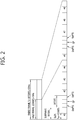
- FIG. 2 shows a structure of a TDD radio frame.
- the TDD radio frame (hereinafter, TDD frame) includes 2 half-frames 10 subframes, and 5 subframes are included in a half-frame, consequently the TDD frame includes total 10 subframes.
- the TDD frame includes an uplink (UL) subframe, a downlink (DL) subframe and a specific subframe (S subframe).
- UL uplink
- DL downlink
- S subframe specific subframe
- a subframe having an index #1 and an index #6 may be a special subframe
- the special subframe includes a downlink pilot time slot (DwPTS), a guard period (GP), and an uplink pilot time slot (UpPTS).
- DwPTS downlink pilot time slot
- GP guard period
- UpPTS uplink pilot time slot
- the DwPTS is used in a UE for initial cell search, synchronization, or channel estimation.
- the UpPTS is used in a BS for channel estimation and uplink transmission synchronization of the UE.
- the GP is a period for removing interference which occurs in an uplink due to a multi-path delay of a downlink signal between uplink and downlink.
- the GP and the UpPTS take a role of a time gap.
- Table 1 shows an example of a UL-DL configuration of a radio frame.
- Uplink-downlink configuration Downlink-to-Uplink Switch-point periodicity
- Subframe number 0 1 2 3 4 5 6 7 8 9 0 5 ms D S U U U D S U U U 1 5 ms D S U U D D S U U D 2 5 ms D S U D D D S U D D 3 10 ms D S U U U D D D D D D 4 10 ms D S U U D D D D D D 5 10 ms D S U D D D D D D D D 6 5 ms D S U U U U D S U U U D S U U D
- 'D' represents a DL subframe
- 'U' represents a UL subframe
- 'S' represents a special subframe. If receiving the UL-DL configuration, the UE may be aware whether each of the subframes in the TDD subframe is a DL subframe (or S subframe) or a UL subframe.
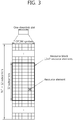
- FIG. 3 shows an example of a resource grid for one DL slot.
- the DL slot includes a plurality of orthogonal frequency division multiplexing (OFDM) symbols in a time domain, and includes N RB resource blocks (RBs) in a frequency domain.
- the RB is a resource allocation unit, and includes one slot in the time domain and includes a plurality of sequential subcarriers in the frequency domain.
- the number N RB of RBs included in the DL slot depends on a DL transmission bandwidth configured in a cell. For example, in the LTE system, N RB may be one in the range of 6 to 110.
- a structure of a UL slot may be the same as the aforementioned structure of the DL slot.
- Each element on the resource grid is referred to as a resource element (RE).
- the RE on the resource grid can be identified by an index pair (k, l) within the slot.
- one resource block includes 7 ⁇ 12 REs consisting of 7 OFDM symbols in the time domain and 12 subcarriers in the frequency domain for example, the number of OFDM symbols and the number of subcarriers in the resource block are not limited thereto.
- the number of OFDM symbols and the number of subcarriers may change variously depending on a cyclic prefix (CP) length, a frequency spacing, etc. For example, if the CP length corresponds to an extended CP, the resource block includes 6 OFDM symbols.
- the number of subcarriers in one OFDM symbol may be selected from 128, 256, 512, 1024, 1536, and 2048.
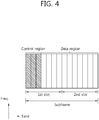
- FIG. 4 shows a structure of a DL subframe.
- the DL subframe is divided into a control region and a data region in the time domain.
- the control region includes up to three (optionally, up to four) preceding OFDM symbols of a first slot in the subframe. However, the number of OFDM symbols included in the control region may vary.
- a physical downlink control channel (PDCCH) and another control channel are allocated to the control region, and a physical downlink shared channel (PDSCH), and a physical broadcast channel (PBCH) are allocated to the data region.
- PDCCH physical downlink control channel
- PDSCH physical downlink shared channel
- PBCH physical broadcast channel
- a physical control format indicator channel (PCFICH) transmitted in a first OFDM symbol of the sub frame carries a control format indicator (CFI) regarding the number of OFDM symbols (i.e., a size of the control region) used for transmission of control channels in the subframe.
- CFI control format indicator
- the UE first receives the CFI on the PCFICH, and thereafter monitors the PDCCH.
- the PCFICH does not use blind decoding, and is transmitted by using a fixed PCFICH resource of the subframe.
- a physical hybrid-ARQ indicator channel which is transmitted from the control region, and carries a positive-acknowledgement (ACK)/negative-acknowledgement (NACK) signal for an uplink hybrid automatic repeat request (HARQ).
- HARQ uplink hybrid automatic repeat request
- the ACK/NACK signal for UL data on a PUSCH transmitted by the UE is transmitted on the PHICH.
- the DCI may include resource allocation of the PDSCH (this is referred to as a DL grant), resource allocation of a PUSCH (this is referred to as a UL grant), a set of transmit power control commands for individual UEs in any UE group, and/or activation of a voice over Internet protocol (VoIP).
- DCI downlink control information
- the DCI may include resource allocation of the PDSCH (this is referred to as a DL grant), resource allocation of a PUSCH (this is referred to as a UL grant), a set of transmit power control commands for individual UEs in any UE group, and/or activation of a voice over Internet protocol (VoIP).
- VoIP voice over Internet protocol
- the BS determines a PDCCH format according to DCI to be transmitted to the UE, attaches a cyclic redundancy check (CRC) to the DCI, and masks a unique identifier (referred to as a radio network temporary identifier (RNTI)) to the CRC according to an owner or usage of the PDCCH.
- CRC cyclic redundancy check
- RNTI radio network temporary identifier
- a unique identifier e.g., cell-RNTI (C-RNTI)
- C-RNTI cell-RNTI
- a paging indication identifier e.g., paging-RNTI (P-RNTI)
- SI-RNTI system information-RNTI
- a random access-RNTI may be masked to the CRC.
- the PDCCH carries control information for a specific UE (such information is called UE-specific control information), and when another RNTI is used, the PDCCH carries common control information received by all or a plurality of UEs in a cell.
- the BS encodes the CRC-attached DCI to generate coded data.
- the encoding includes channel encoding and rate matching. Thereafter, the BS modulates the coded data to generate modulation symbols, and transmits the modulation symbols by mapping the symbols to a physical resource element (RE).
- RE physical resource element
- a PDSCH transmitted in the data region is a downlink data channel.
- System information, data, etc. can be transmitted through the PDSCH.
- the PBCH carries system information necessary for communication between the UE and the BS.
- the system information transmitted through the PBCH is referred to as a master information block (MIB).
- MIB master information block
- SIB system information transmitted on the PDCCH
- FIG. 5 shows a structure of a UL subframe.
- the UL subframe can be divided into a control region and a data region.
- the control region is a region to which a physical uplink control channel (PUCCH) carrying UL control information is allocated.
- the data region is a region to which a physical uplink shared channel (PUSCH) carrying user data is allocated.
- PUCCH physical uplink control channel
- PUSCH physical uplink shared channel
- the PUCCH is allocated in an RB pair in a subframe. RBs belonging to the RB pair occupy different subcarriers in each of a first slot and a second slot.
- FIG. 6 shows a frame structure for synchronization signal transmission in the conventional FDD frame.
- a slot number and a subframe number start from 0.
- a synchronization signal is a signal used when a cell search is performed, and includes a primary synchronization signal (PSS) and a secondary synchronization signal (SSS).
- PSS primary synchronization signal
- SSS secondary synchronization signal
- the synchronization signal can be transmitted in each of subframes #0 and #5 by considering a global system for mobile communication (GSM) frame length of 4.6 ms to facilitate inter-RAT measurement.
- GSM global system for mobile communication
- a boundary for the frame can be detected through the SSS. More specifically, in the FDD system, the PSS is transmitted in a last OFDM symbol of 0 th and 10 th slots, and the SSS is transmitted in an immediately previous OFDM symbol of the PSS.
- the synchronization signal can transmit 504 physical cell IDs by combining 3 PSSs and 168 SSSs.
- a physical broadcast channel (PBCH) is transmitted in first 4 OFDM symbols of a first slot.
- PBCH physical broadcast channel
- the synchronization signal and the PBCH are transmitted within 6 RBs in a system bandwidth, so as to be detected or decoded by a UE irrespective of a transmission bandwidth.
- a physical channel for transmitting the PSS is called a P-SCH
- a physical channel for transmitting the SSS is called an S-SCH.
- a transmit diversity scheme of the synchronization signal uses only a single antenna port, and is not separately defined in the standard. That is, single antenna transmission or UE-transparent transmission (e.g., precoding vector switching (PVS), time switched transmit diversity (TSTD), cyclic delay diversity (CDD)) can be used.
- PVS precoding vector switching
- TSTD time switched transmit diversity
- CDD cyclic delay diversity
- a length-63 Zadoff-Chu (ZC) sequence is defined in a frequency domain and is used as a sequence of the PSS.
- the ZC sequence is defined by Equation 1.
- a sequence element corresponding to a DC subcarrier, i.e., n 31, is punctured.
- Nzc 63.
- d u n e ⁇ j ⁇ un n + 1 N ZC
- d u n ⁇ 1 n d N ZC ⁇ u n ⁇ , when N ZC is even number .
- d u n d N ZC ⁇ u n ⁇ , when N ZC is odd number .
- a sequence used for the SSS is used by interleaving two m-sequences having a length of 31.
- the SSS can transmit 168 cell group IDs by combining two sequences.
- An m-sequence used as a sequence of the SSS is robust to a frequency selective environment, and can decrease a computation amount according to a fast m-sequence transform using a fast Hadamard transform.
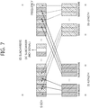
- FIG. 7 shows a case where two sequences in a logical domain are interleaved and mapped in a physical domain.
- an SSS of a subframe 0 transmits a cell group ID by combining the two sequences (S1, S2)
- an SSS of a subframe 5 is transmitted by swapping to (S2, S1), thereby being able to identify a boundary of 10 m frame.
- the SSS code used herein uses a generator polynomial of x 5 + x 2 + 1, and 31 codes can be generated by using different circular shifts.
- PSS-based sequences are defined and then are scrambled to an SSS such that different sequences are scheduled to S1 and S2. Thereafter, an S1-based scheduling code is defined, and scheduling is performed on S2.
- an S1-based scheduling code is defined, and scheduling is performed on S2.
- a code of the SSS is swapped in a unit of 5 ms, whereas the PSS-based scrambling code is not swapped.
- the PSS-based scrambling code can be defined as a version of 6 circular shifts according to an index of PSS at an m-sequence generated from a generator polynomial of x 5 + x 3 + 1.
- the S1-based scrambling code can be defined as a version of 8 circular shifts according to an index of S1 at an m-sequence generated from a generator polynomial of x 5 + x 4 + x 3 + x 2 + x 1 + 1.
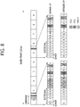
- FIG. 8 shows a frame structure for transmitting a synchronization signal in the conventional TDD frame.
- a PSS is transmitted in a third OFDM symbol of third and 13 th slots.
- An SSS is transmitted three OFDM symbols earlier than the OFDM symbol in which the PSS is transmitted.
- a PBCH is transmitted in first 4 OFDM symbols of a second slot of a first subframe.
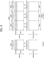
- FIG. 9 shows an example of comparing a single-carrier system and a carrier aggregation system.
- only one carrier is supported for a UE in an uplink and a downlink in the single-carrier system.
- the carrier may have various bandwidths, only one carrier is assigned to the UE.
- multiple component carriers (CCs) i.e., DL CCs A to C and UL CCs A to C
- CA carrier aggregation
- three 20 MHz CCs can be assigned to allocate a 60 MHz bandwidth to the UE.
- the carrier aggregation system can be divided into a contiguous carrier aggregation system in which carriers are contiguous to each other and a non-contiguous carrier aggregation system in which carriers are separated from each other.
- a contiguous carrier aggregation system in which carriers are contiguous to each other
- a non-contiguous carrier aggregation system in which carriers are separated from each other.
- a CC which is a target when aggregating one or more CCs can directly use a bandwidth that is used in the legacy system in order to provide backward compatibility with the legacy system.
- a 3GPP LTE system can support a carrier having a bandwidth of 1.4 MHz, 3 MHz, 5 MHz, 10 MHz, 15 MHz, and 20 MHz
- a 3GPP LTE-A system can configure a broadband of 20 MHz or higher by using each carrier of the 3GPP LTE system as a CC.
- the broadband can be configured by defining a new bandwidth without having to directly use the bandwidth of the legacy system.
- a frequency band of a wireless communication system is divided into a plurality of carrier frequencies.
- the carrier frequency implies a center frequency of a cell.
- the cell may imply a downlink frequency resource and an uplink frequency resource.
- the cell may also imply combination of a downlink frequency resource and an optional uplink frequency resource.
- CA carrier aggregation
- the UE In order to transmit and receive packet data through a specific cell, the UE first has to complete a configuration of the specific cell.
- the configuration implies a state of completely receiving system information required for data transmission and reception for the cell.
- the configuration may include an overall procedure that requires common physical layer parameters necessary for data transmission and reception, media access control (MAC) layer parameters, or parameters necessary for a specific operation in a radio resource control (RRC) layer.
- MAC media access control
- RRC radio resource control
- a cell of which configuration is complete is in a state capable of immediately transmitting and receiving a packet upon receiving only information indicating that packet data can be transmitted.
- the cell in a state of completing its configuration can exist in an activation or deactivation state.
- the activation implies that data transmission or reception is performed or is in a ready state.
- the UE can monitor or receive a control channel (i.e., PDCCH) and a data channel (i.e., PDSCH) of an activated cell in order to confirm a resource (e.g., frequency, time, etc.) allocated to the UE.
- a control channel i.e., PDCCH
- a data channel i.e., PDSCH
- the deactivation implies that transmission or reception of traffic data is impossible and measurement or transmission/reception of minimum information is possible.
- the UE can receive system information (SI) required for packet reception from a deactivated cell.
- SI system information
- the UE does not monitor or receive a control channel (i.e., PDCCH) and a data channel (i.e., PDSCH) of the deactivated cell in order to confirm a resource (e.g., frequency, time, etc.) allocated to the UE.
- a control channel i.e., PDCCH
- PDSCH data channel allocated to the UE.
- a cell can be classified into a primary cell, a secondary cell, a serving cell, etc.
- the UE When carrier aggregation is configured, the UE has only one RRC connection with the network.
- RRC connection establishment/re-establishment, handover process one cell provides non-access stratum (NAS) mobility information and a security input.
- NAS non-access stratum
- Such a cell is called a primary cell.
- the primary cell implies one serving cell which provides a security input in an RRC connection establishment procedure/connection reestablishment procedure/handover procedure performed by the UE with respect to the BS.
- the secondary cell implies a cell configured to provide an additional radio resource after establishing an RRC connection through the primary cell.
- the serving cell is configured with the primary cell in case of a UE of which carrier aggregation is not configured or which cannot provide the carrier aggregation. If the carrier aggregation is configured, the term 'serving cell' is used to indicate a cell configured for the UE, and the cell may be plural in number.
- a plurality of serving cells may be configured with a set consisting of a primary cell and one or a plurality of cells among all secondary cells.
- a primary component carrier denotes a CC corresponding to the primary cell.
- the PCC is a CC that establishes an initial connection (or RRC connection) with the BS among several CCs.
- the PCC serves for connection (or RRC connection) for signaling related to a plurality of CCs, and is a CC that manages a UE context which is connection information related to the UE.
- the PCC establishes a connection with the UE, and thus always exists in an activation state when in an RRC connected mode.
- a downlink CC corresponding to the primary cell is called a downlink primary component carrier (DL PCC)
- an uplink CC corresponding to the primary cell is called an uplink primary component carrier (UL PCC).
- DL PCC downlink primary component carrier
- U PCC uplink primary component carrier
- a secondary component carrier denotes a CC corresponding to a secondary cell. That is, the SCC is a CC allocated to the UE in addition to the PCC.
- the SCC is an extended carrier used by the UE for additional resource allocation or the like in addition to the PCC, and can be in an activation state or a deactivation state.
- a DL CC corresponding to the secondary cell is called a DL secondary CC (SCC).
- a UL CC corresponding to the secondary cell is called a UL SCC.
- the primary cell and the secondary cell have the following features from a perspective of each UE.
- the primary cell is used for PUCCH transmission.
- the primary cell is always activated, whereas the secondary cell is activated/deactivated according to a specific condition.
- the primary cell can change by a handover procedure accompanied by a random access channel (RACH) procedure or security key modification.
- the primary cell in case of an FDD system, the primary cell always consists of a pair of a DL PCC and a UL PCC. Seventh, for each UE, a different CC can be configured as the primary cell. Eighth, the primary cell can be replaced only through a handover, cell selection/cell reselection process.
- RRC signaling can be used for transmission of system information of a dedicated secondary cell.
- a DL CC can construct one serving cell. Further, the DL CC can be connected to a UL CC to construct one serving cell. However, the serving cell is not constructed only with one UL CC.
- Activation/deactivation of a CC is equivalent to the concept of activation/deactivation of a serving cell. For example, if it is assumed that a serving cell 1 consists of a DL CC 1, activation of the serving cell 1 implies activation of the DL CC 1. If it is assumed that a serving cell 2 is configured by connecting a DL CC 2 and a UL CC 2, activation of the serving cell 2 implies activation of the DL CC 2 and the UL CC 2. In this sense, each CC can correspond to a cell.
- the number of CCs aggregated between a downlink and an uplink may be determined differently. Symmetric aggregation is when the number of DL CCs is equal to the number of UL CCs. Asymmetric aggregation is when the number of DL CCs is different from the number of UL CCs.
- the CCs may have different sizes (i.e., bandwidths). For example, if 5 CCs are used to configure a 70 MHz band, it can be configured such as 5 MHz CC(carrier #0) + 20 MHz CC(carrier #1) + 20 MHz CC(carrier #2) + 20 MHz CC(carrier #3) + 5 MHz CC(carrier #4).
- the carrier aggregation system can support multiple component carriers (CCs) unlike a single-carrier system.
- CCs component carriers
- one UE may transmit and receive data/control information using multiple cells.
- the UE uses a cell that is initially connected as a primary cell, and uses the cell that is additionally configured through the primary cell as a secondary cell.
- the primary cell is used for the operation for maintaining the connection between a BS and a UE.
- the operations such as radio link management (RLM), radio resource management (RRM), reception of system information, physical random access channel (PRACH) transmission, uplink control channel (PUCCH) transmission, and the like.
- the secondary cell is mainly used for the transmission of the scheduling information for data channels or the data channels.
- the primary cell and the secondary cell are UE-specific.
- each of the cells may be used for the primary cell or the secondary cell, and each of the UEs uses one of the multiple cells as the primary cell. That is, an arbitrary cell may be used as the primary cell or the secondary cell. Accordingly, all of the cells are configured to perform the operation of the primary cell.
- all of the cells are expected to implement all of these operations such as the transmission of synchronization signal, the transmission of broadcast channel, the transmission of CRS, the configuration of PDCCH region, and the like are implemented.
- Those cells may be referred to as backward compatible cells or legacy carrier type (LCT) in the aspect of carrier.
- LCT legacy carrier type
- a cell is used as the secondary cell in the future wireless communication system, it is considered to introduce the cell of which a part or all of the unnecessary information is removed.
- a cell may be represented not to have backward compatibility, and referred to as a new carrier type (NCT) or extension carrier in comparison with the LCT.
- NCT new carrier type
- the NCT may be configured to transmit the CRS only at a part of time interval or only at frequency interval without transmitting in every subframe, or the DL control channel region may be newly configured, which is specified for each UE by removing the DL control channel region such as existing PDCCH or reducing to a time region or frequency region.
- Such an NCT may be a carrier in which only DL transmission is allowed.
- the carrier in which only DL transmission is allowed is short for a DL only carrier, for the convenience.
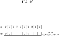
- FIG. 10 exemplifies the DL only carrier.
- the DL only carrier may be configured by various methods.
- the DL only carrier may be a cell in which only DL CC exists. That is, as shown in FIG. 10(a) , in FDD, the DL only carrier may be the DL CC in which corresponding UL CC does not exist. Or, even for the DL CC in which exists the UL CC that is linked by system information block (SIB), the DL only carrier may be configured by setting to use only DL CC without using the UL CC.
- SIB system information block
- the DL only carrier uses the UL-DL configuration of Table 1 and it is available to be generated to use the DL subframe only according to the corresponding UL-DL configuration.
- UL subframe/DL subframe are included by time division in a frame according to the UL-DL configuration defined in Table 1, but in the DL only carrier, only DL subframe is included as shown in FIG. 10(b) .
- such a method causes resource waste since the subframe which is supposed to be configured as UL subframe is not going to be used according to the UL-DL configuration.
- the DL only carrier is used in TDD, it is preferable that all of the subframes in a frame are comprised of DL subframes only.
- UL-DL configurations 0 to 6 are the same as those of the existing UL-DL configuration, and the UL-DL configuration 7 is added onto it.
- the UL-DL configuration 7 represents that all of the subframes in a frame are configured as DL subframe. It may be limited that UL-DL configuration 7 is used only for the secondary cell without being used for the primary cell. In other words, in order to avoid interference between frequency bands, it may be limited that the DL only carrier use only frequency band (the secondary cell) which is different from that of the existing TDD primary cell.
- the BS and the UE may configure the DL only carrier using the following method. That is, the BS transmits the UL-DL configuration and switch information.
- the UL-DL configuration may be one of the existing UL-DL configurations 0 to 6 of Table 1.
- the switch information may be the information that represents UL whether it is changed to the UL subframe in the corresponding UL-DL configuration, and whether it is changed to the DL subframe of a special subframe. According to the switch information, all of the UL subframes (or S subframe) in a frame may be switched to the DL subframe, or only a part of UL subframes (or S subframe) may be switched to DL subframe.
- the switch information may be implemented in various ways. For example, the switch information represents whether the UL subframe (or S subframe) has been used or not, but what the UL subframe (or S subframe) has been not used may mean that the UL subframe (or S subframe) is used as a DL subframe.
- the configuration of the DL only carrier it may be applied for the method of stopping the use of the UL subframe (for example, only suspending the channel which is transmitted from the first SC-FDMA symbol are transmitted in the UL subframe such as PUSCH, PUCCH, and so on but available to use the channel which is transmitted from the last SC-FDMA symbol of the UL subframe such as SRS) or the method that the configuration of the UL subframe is changed to the DL subframe to use.
- the UE if the switch information is detected, switches the UL subframe (or the S subframe) of the UL-DL configuration to the DL subframe.
- the switch information may transmit in the corresponding cell-specific signaling or UE-specific signaling.
- the DL only carrier use is used for the carrier aggregation, there is an advantage that the DL only carrier use above is shared as the secondary cell between the FDD terminal and the TDD terminal in common.
- the NCT may be a carrier in which only UL transmission is allowed.
- the carrier in which only UL transmission is allowed is short for a UL only carrier, for the convenience.
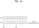
- FIG. 11 exemplifies the UL only carrier.
- the UL only carrier may be configured by various methods.
- the UL only carrier may be a cell in which only UL CC exists. That is, as shown in FIG. 12(a) , in FDD, the UL only carrier may be the DL CC in which corresponding UL CC does not exist. Or, even for the UL CC in which exists the UL CC that is linked by system information block (SIB), the UL only carrier may be configured by setting to use only UL CC without using the DL CC.
- SIB system information block
- the UL only carrier uses the UL-DL configuration of Table 1 and it is available to be generated to use only UL subframe without using the DL subframe according to the corresponding UL-DL configuration.
- UL subframe/DL subframe are included by time division in a frame according to the UL-DL configuration defined in Table 1, but in the UL only carrier, only UL subframe is included as shown in FIG. 10(b) .
- such a method causes resource waste since the subframe (for example, 101 and 102) which is supposed to be configured as DL subframe is not going to be used according to the UL-DL configuration.
- the UL only carrier is used in TDD, it is preferable that all of the subframes in a frame are comprised of UL subframes only.
- UL-DL configurations 0 to 6 are the same as those of the existing UL-DL configuration, and the UL-DL configuration 7 is added onto it.
- the UL-DL configuration 7 represents that all of the subframes in a frame are configured as UL subframe. It may be limited that UL-DL configuration 7 is used only for the secondary cell without being used for the primary cell. In other words, in order to avoid interference between frequency bands, the UL only carrier may be used for the secondary cell in a different frequency band which is different from that of the existing TDD primary cell.
- the method above may define the UL-DL configuration 7 in order to configure the DL only carrier and directly notify it to a UE.
- a BS selects one of the DL only carrier and the UL only carrier and aggregates it as a secondary cell
- UL-DL configuration 7 of Table 2 may be added to Table 3. That is, total nine UL-DL configurations may be included in Table 3, and UL-DL configuration 7 of Table 2 may be added to Table 3 as UL-DL configuration 8.
- a BS uses the existing UL-DL configurations 0 to 6 but may additionally use the method of transmitting information indicating the DL only carrier or the UL only carrier.
- FIG. 12 shows another example of configuring the UL only carrier.
- the BS transmits the UL-DL configuration and switch information (S101).
- the UL-DL configuration may be one of the existing UL-DL configurations 0 to 6 of Table 1.
- the switch information may be the information that represents DL whether it is changed to the DL subframe in the corresponding UL-DL configuration, and whether it is changed to the UL subframe of a special subframe. According to the switch information, all of the DL subframes (or S subframe) in a frame may be switched to the UL subframe, or only a part of DL subframes (or S subframe) may be switched to UL subframe.
- the switch information may be implemented in various ways. For example, the switch information represents whether the DL subframe (or S subframe) has been used or not, but what the DL subframe (or S subframe) has been not used may mean that the DL subframe (or S subframe) is used as a UL subframe.
- the UL only carrier For the configuration of the UL only carrier, it may be applied for the method of stopping the use of the DL subframe (for example, only suspending the channel which is transmitted to the last OFDM symbol are transmitted in the DL subframe such as PDSCH and so on but available to use the channel which is transmitted from a part of OFDM symbol of DL subframe such as PCFICH, PDCCH, PHICH, channel state information reference signal (CSI-RS) and cell-specific reference signal (CRS)) or the method that the configuration of the DL subframe is changed to the UL subframe to use.
- CSI-RS channel state information reference signal
- CRS cell-specific reference signal
- the case of changing the S subframe to the UL subframe is available owing to not using the DL subframe, and in case of changing the DL subframe to the UL subframe and using it without changing the DL subframe to the UL subframe that doesn't contain the DwPTS and GP, it is available to use unnecessary DwPTS and CP in uplink.
- the SRS, the transmission of PRACH and so on in the existing UL-DL configuration may be applied same as the existing definition without any changes.
- the UE if the switch information is detected, switches the DL subframe (or the S subframe) of the UL-DL configuration to the UL subframe (step, S102).
- the switch information may be transmitted by the corresponding cell-specific signaling or UE-specific signaling.
- the method of defining UL-DL configuration 7 and notifying it directly to the UE in order to configure the UL only carrier and the method with referring to FIG. 12 may be used together.
- all subframes of the UL only carrier may be used as the UL subframe, or a part of subframes of the UL only carrier may be used as the UL subframe.
- the UL only carrier may exceptionally include the DL subframe that transmits essential information such as PSS/SSS and system information. That is, the UL only carrier may be defined as the carrier in which all subframes in the frame except the DL subframe that transmits the essential information by the BS are configured as the UL subframe.
- the FDD UE and TDD UE may share the UL only carrier as the secondary cell.
- the carrier that is comprised of the UL only carriers and available to be aggregated is not limited to the NCT, but may be applied to the LCT.
- the primary cell may be the cell that operates as the TDD or the cell that operates as the FDD, and the secondary cell may be the UL only carrier.
- a cell identity is required.
- the cell ID is used for generating the UL channel/signal, and the existing cell ID may be acquired by the PSS/SSS.
- the UL only carrier is comprised only UL subframes, it may be problematic since there is no DL subframe to receive the signal which is required to acquire a cell ID.
- the BS notifies the bit-sequence of the same length as the cell ID through the primary cell, and it may be used for a virtual cell ID.
- the UE may use the cell ID of the DL carrier which is linked above as the virtual cell ID and use it as the UL signal/channel.
- the UE may use the cell ID of the DL subframe as the virtual cell ID and use it as the UL signal/channel.
- the UL grant for the PUSCH which is to be transmitted from the UL subframe of the secondary cell is going to be transmitted by the BS (this is referred as a UL grant-PUSCH timing).
- the ACK/NACK for the PUSCH that is transmitted from the UL subframe of the secondary cell by the UE is going to be transmitted through the PHICH of which DL subframe of the secondary cell (this is referred as a PUSCH-PHICH timing).
- Table 4 above represents the k value in case that the UL grant that the BS transmits in the DL subframe n schedules the PUSCH that a UE transmits in subframe n + k.
- the UL grant in subframe 0 that is the DL subframe represents subframe 0 + 4 that is the UL subframe, that is, to schedule the PUSCH of subframe 4.
- the case that the number of the UL subframe in a frame is more than the number of DL subframe may occur. Then, since one UL grant may schedule multiple UL subframes, the case that k value in Table 4 is multiple occurs.
- Table below represents the existing PUSCH-PHICH timing according to the UL-DL configuration.
- Table 5 TDD UL/DL Configuration Subframe number n 0 1 2 3 4 5 6 7 8 9 0 4 7 6 4 7 6 1 4 6 4 6 2 6 6 3 6 6 6 4 6 6 5 6 6 4 6 6 4 7
- Table 5 represents k PHICH values in case that a BS the ACK/NACK for the PUSCH through the PHICH of DL subframe n + k PHICH .
- Table 5 represents k PHICH values in case that a BS the ACK/NACK for the PUSCH through the PHICH of DL subframe n + k PHICH .
- Table 5 above may be represented as Table 6 below.
- Table 6 represents the k value in case that the PHICH in DL subframe i carries the ACK/NACK for the PUSCH which is transmitted in UL subframe i - k.
- Table 6 TDD UL/DL Configuration Subframe number i 0 1 2 3 4 5 6 7 8 9 0 7/6 4 7/6 4 1 4 4 6 2 6 6 3 6 6 6 4 6 6 6 5 6 6 6 4 7 4 6
- the case that the number of the UL subframe in a frame is more than the number of DL subframe may occur.
- the number of UL subframe is more than that of the DL subframe.
- the ACK/NACK for multiple PUSCHs may be transmitted in one UL subframe.
- the ACK/NACK for multiple PUSCHs may be transmitted.
- the UL only carrier is added in the primary cell as the secondary cell, it is problematic how to determine the timing between the UL grant of the primary cell and the PUSCH of the secondary cell (UL grant-PUSCH timing) and the timing between the PUSCH of the secondary cell and the PHICH of the primary cell.
- the existing FDD has the HARQ-ACK timing when transmitting the ACK/NACK for a data unit (for example, a transmission block, codeword, and etc.) that a UE receives in subframe n - 4 by subframe n.
- a data unit for example, a transmission block, codeword, and etc.
- Table 7 shown above represents the corresponding relation of the DL subframe n - k m that corresponds to UL subframe n in each UL-DL configuration as the value of k m . That is, it signifies that the ACK/NACK for the PDSCH which is transmitted from subframe n - k m is transmitted from UL subframe n.
- the PUSCH-PHICH timing may follow the HARQ-ACK timing which is configured by the UL-DL configuration of a primary cell.
- the ACK/NACK for the PUSCH which is transmitted from subframe 2 of the primary cell is transmitted through the PHICH of subframe 6 of the primary cell. Accordingly, the ACK/NACK for the PUSCH which is transmitted from subframe 2 of the secondary cell is also transmitted through the PHICH of subframe 6 of the primary cell.
- the number of DL subframe is more than that of the UL subframe in a frame among the UL-DL configurations.
- UL-DL configurations 0, 3, 6, and the like have more DL subframes more than UL subframes.
- the DL HARQ-ACK timing according to the UL-DL configuration that has more DL subframes may be used as the HARK-ACK reference timing of a secondary cell.
- the UL subframes according to the UL-DL configuration of the secondary cell should be subset of the UL subframes according to the UL-DL configuration of a primary cell.
- the HARQ-ACK timing according to UL-DL configurations 0 and 6 may be used as the HARK-ACK reference timing of a secondary cell.
- the HARQ-ACK timing according to UL-DL configurations 0, 3 or 6 may be used as the HARK-ACK reference timing of a secondary cell.
- Method 1 or 2 described above according to the UL-DL configuration which is applied to the UL subframe of the secondary cell which is overlapped with the DL subframe of the primary cell or to the secondary cell, it is required to be additionally determined the UL grant-PUSCH timing for the UL subframe of the secondary cell that corresponds to the DL subframe and the PUSCH-PHICH timing.
- the DL subframe in which the UL grant or PHICH is transmitted is the DL subframe of the primary cell according to the UL-DL configuration of the primary cell or the DL subframe of the primary cell according to the UL-DL configuration which is applied to the secondary cell.
- the S subframe may not be included in the DL subframe and may be included only for specific UL-DL configuration.
- the DL subframe in which the UL grant or PHICH is transmitted may be considered except subframes 0, 1, 5 and 6 which are fixed as the DL subframe for all UL-DL configurations.
- Methods 3 to 7 are for the case on which way UL the subframe n + k is determined when a UE receives the UL grant from the DL subframe n of the primary cell and transmits the PUSCH which is scheduled by the UL grant from the UL subframe n + k of the secondary cell.
- Method 4 is the method that the number of UL grant transmitted from each DL subframe is to be equally arranged in the multiple DL subframes preferably without being biased to a specific DL subframe by equalizing the number of DL subframe of the primary cell that corresponds to each UL subframe of the secondary cell preferably.
- the DL subframe of the primary cell where the UL grant is to be located for the PUSCH which is to be transmitted from each subframe of the secondary cell is determined.
- the maximum number of UL grant that is available to be transmitted by one DL subframe is determined, and if it exceed the maximum number of the UL grant, it can be determined that the UL grant that exceeds the maximum number is to be transmitted from the next DL subframe or the previous DL subframe.
- the DL subframe is changed such that the UL grant for the forgoing PUSCH is not to be located later than the UL grant for the following PUSCH.
- the maximum number of UL grant may be changed according to the UL-DL configuration.
- the method of equally distributing with including the timing in the existing UL-DL configuration, or the method of equally distributing with new timing, that is, the timing which is added in case of using the secondary cell as the UL only carrier can be considered.
- the UL grant-PUSCH timing as represented by Table 8 below may be added to Table 4.
- Table 8 UL/DL Configuration (PCell)
- PCell UL/DL Configuration
- Subframe number n 0 1 2 3 4 5 6 7 8 9 0 5 5 5 5 1 4, 5 5 4, 5 5 2 4 4, 5 4 4 4, 5 4 3 6 6, 7 4 4 4 6 4 4, 5 5, 6 4 4 4 4 4 5 4 4, 5 4 4 4 4 4 6 6 8 5 5 6
- the UL grant-PUSCH timing as represented by Table 9 may be added to Table 4.
- Table 9 UL/DL Configuration(PCell) Subframe number n 0 1 2 3 4 5 6 7 8 9 0 5 5 5 5 1 5 5 5 5 5 5 2 5 5 5 5 5 5 5 5 5 5 3 7 7 4 4 4 7 7 4 6 6 4 4 4 4 6 6 5 5 5 4 4 4 4 4 4 5 5 6 6 8 5 5 6
- FIG. 13 shows the UL grant-PUSCH timing in case that Method 1 and Method 4 are combined.
- the primary cell is a TDD cell according to UL-DL configuration 1, and the secondary cell uses the UL only carrier.
- the secondary cell is comprised of only UL subframes.
- the UL grant which is located in the DL subframe 21 of the primary cell is for the PUSCH of the UL subframe of the secondary cell. That is, the UL subframe 122 of the secondary cell is determined according to the UL grant-PUSCH timing of the primary cell.
- the solid arrow lines in FIG. 13 represents the UL subframe of the secondary cell which is determined according to the UL grant-PUSCH timing of the primary cell.
- the UL grant-PUSCH timing of the UL subframe of the secondary cell which is overlapped with the DL subframe of the primary cell is set according to Method 4, becomes the UL grant-PUSCH timing shown by the dotted arrow lines in FIG. 13 .
- the UL grant for the PUSCH which is located in the subframe 123 is transmitted from the DL subframe 124, not from the closest DL subframe which is located behind 4 subframes. This is for equal distribution.
- the maximum number of UL grant which is available to be transmitted from one DL subframe may be two.
- Method 6 is the method of signaling the relation between the UL subframe where the PUSCH is transmitted from the secondary cell and the DL subframe of the primary cell where the corresponding UL grant is transmitted by radio resource control (RRC).
- RRC radio resource control
- Method 6 may be applied to overall UL subframes of the secondary cell as well as to the UL subframe of the secondary cell which is overlapped with the DL subframe of the primary cell, and also may be commonly or partly applied to the case of aggregating carriers having different UL-DL configurations.
- the UL grants for each UL subframe may be individually coded or schedule multiple PUSCHs by one UL grant.
- the PUSCH-PHICH timing will be described below in case that the UL only carrier is added as the secondary cell.
- a BS selects the fastest DL subframe that satisfies the minimum required time which is available to transmit the PHICH after receiving the PUSCH. If the number of PHICH which is to be transmitted from the selected DL subframe exceeds a predetermined value, the exceeded PHICH may be transmitted from the next DL subframe of the fastest DL subframe.
- the equal distribution may be performed with the existing PUSCH-PHICH timing being included in addition to the existing UL-DL configuration, or may be performed for only new timing which is added by configuring the UL only carrier as the secondary cell.
- new PHICH resource may be configured in the PDSCH region of the DL subframe and used.
- the new PHICH resource is referred to as an enhanced-PHICH (E-PHICH) resource.
- the subframe that has the PHICH or e-PHICH resource among the DL subframes of the primary cell is only configured as the equal distribution object for PHICH transmission, and the only configured DL subframes are equally distributed by Method 9.
- the equal distribution may be performed with the existing PUSCH-PHICH timing being included in addition to the existing UL-DL configuration, or may be performed for only new timing which is added by configuring the UL only carrier as the secondary cell.
- the PHICH is equally distributed following Method 9, but it may be limited that the UL HARQ process of the secondary cell that corresponds to the DL subframe that does not have the PHICH resource among the DL subframes of the primary cell is to be performed by only UL grant without the PHICH.
- the equal distribution may be performed with the existing PUSCH-PHICH timing being included in addition to the existing UL-DL configuration, or may be performed for only new timing which is added by configuring the UL only carrier as the secondary cell.
- the PHICH is equally distributed following Method 9, but the UL HARQ process which is performed in the UL subframe of the secondary cell which is overlapped with the DL subframe of the primary cell may be retransmitted only by the UL grant without the PHICH.
- the PUSCH transmission that does not required to retransmit to the UL subframe may be allowed.
- this includes non-periodic CSI transmission, transmission of the CSI using the PUSCH and ACK/NACK, and so on.
- Method 13 may be performed even though the UL-DL configuration which is comprised of the UL subframe in the UL-DL configuration of Table 3 is not introduced.
- the existing configurations 0 to 6 are allocated to the UL only carrier, but it is not required to configure the DwPTS, GP and UwPTS since the DL subframe is not used, and all of the S sub frames may be used as the same structure as different UL sub frames.
- the BS may perform signaling of notifying that it is the UL only carrier together with the UL-DL configuration information.
- the signaling may include the information of notifying whether the DL subframe is used in the corresponding UL-DL configuration and whether all of the S subframe is used as the UL subframe.
- RRC radio resource control
- This method may be applied to overall UL subframes of the secondary cell as well as to the UL subframe of the secondary cell which is overlapped with the DL subframe of the primary cell. In addition, this may also be commonly or partly applied to the case of aggregating cells having different UL-DL configurations.
- the DL subframe in which the PHICH resource is not configured in the PDCCH region in Methods 8 to 15 may be the DL subframes in which numeral is not filled in.
- FIG. 14 illustrates the PUSCH-PHICH timing in case of combining Method 1 and Method 9, 10, 11 or 12.
- the DL subframes where the PHICH is located are equally distributed.
- Maximum 2 PHICHs for the UL subframes may be transmitted to one DL subframe.
- 3 PHICHs for the UL subframes may be transmitted to one DL subframe.
- the PHICH for the PUSCH which is transmitted from some UL subframe 131 among the UL subframes of the secondary cell which are overlapped with the DL subframes of the primary cell is not transmitted from the primary cell.
- the PUSCH for some UL subframe 131 may not be scheduled.
- the PHICH for the PUSCH which is transmitted from respective UL subframes of the secondary cell which are overlapped with the DL subframes of the primary cell is not transmitted from the primary cell.
- HARQ retransmission is performed only by the UL grant.
- the PUSCH may not be scheduled for the UL subframes of the secondary cell which are overlapped with the DL subframes of the primary cell.
- Table 10 represents the k PHICH value for the UL subframes of the secondary cell which are overlapped with the DL subframes of the primary cell in case that Method 1 and Method 9 are combined and applied, and represents the values added to Table 5.
- PCell UL/DL Configuration
- Table 10 below in case of transmitting the PUSCH from the subframe n of the secondary cell and transmitting the PHICH that corresponds to the PUSCH from the subframe n + k PHICH (that is, the channel that transmits the ACK/NACK for the PUSCH), represents the k PHICH .
- Table 11 below, in case that the PHICH in the DL subframe i of the primary cell is the response to the PUSCH which is transmitted from the UL subframe i - k of the secondary cell, represents the k value for the DL subframe i.
- Table 11 represents k values added to Table 6.
- UL/DL Configuration(PCell) Subframe number i 0 1 2 3 4 5 6 7 8 9 0 5 5 5 5 1 5 5 5 5 5 5 5 2 5 5 5 5 5 5 5 5 5 5 5 5 3 4 4 7 7 7 7 4 4 4 4 6 6 6 6 4 4 5 4 4 5 5 5 5 4 4 4 6 5 5 6 8
- Table 12 represents additional k PHICH value in case that Method 9 is combined with Method 1 and applied.
- Table 12 UL/DL Configuration(PCell) Subframe number n 0 1 2 3 4 5 6 7 8 9 0 5 5 5 5 1 4,5 5 4,5 5 2 4,5 4,5 5 5 5 5 5 3 7 7 4 4 4 7 7 4 6 6 4 4 4 4 6 6 5 5 5 4 4 4 4 4 5 5 6 6 8 5 5 6
- the UL grant and PHICH may not transmitted to the same cell. That is, it operates as the cell not having the PHICH. Accordingly, it is assumed that a UE receives ACK for the PUSCH which is transmitted by UL only carrier without the PHICH, or may receive the PHICH in the cell that receives the UL grant of the corresponding PUSCH. Or, the UE may receive the PHICH in the cell which is designated as the RRC or receive the PHICH in different cell having the UL-DL configuration which is the same as the UL only carrier. Or, in case of using the UL only carrier that uses only UL subframe which is determined according to the UL-DL configuration, the UE may receive the PHICH without receiving the scheduling in from the DL subframe.
- the DL only carrier or the UL only carrier may be DL carrier or UL carrier that is selected in the cell defined as a pair of UL carrier and DL carrier.
- the BS notifies the cell ID of the cell that is defined as the pair of UL carrier and DL carrier to the UE, and may signal the information to the UE whether the both UL carrier and DL carrier are aggregated at the same time or either one is aggregated in the cell that is defined as the pair of the UL carrier and the DL carrier.
- the above information may be comprised of two- bit bitmap, and each bit of the bitmap may correspond to each UL carrier and DL carrier of the cell that is defined as a pair of the UL carrier and DL carrier. According to each bit value, it is available to inform which one is aggregated to the secondary cell of the UL carrier and the DL carrier.
- the information may be performed dynamically with L2/L1 signaling.
- L2 signaling it is available to directly indicate the MAC message that is including the information that indicates the DL carrier and the UL carrier. Or for example of an indirect method, it is also available to notify activation/non-activation that are applied to DL carrier/UL carrier in common by existing cell unit with separating by DL carrier/ UL carrier.
- L1 signaling it is available to notify by using an exclusive control channel that sets up carrier or DL/UL scheduling control channel. In case of using the DL/UL scheduling control channel, it may be set up to ignore the DL/UL scheduling.
- DL only carrier or UL only carrier are aggregated in the primary cell that is operated in TDD or FDD
- by notifying the cell ID of the cell defined for TDD (that is, the cell that is configured with the carrier having the mixture of DL/UL subframes) and the cell that corresponds to the cell ID above may be aggregated to the secondary cell.
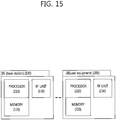
- Figure 15 is a block diagram illustrating a wireless device in which an embodiment of the present invention is implemented.
- a BS 100 includes a processor 110, a memory 120, and a radio frequency (RF) unit 130.
- the processor 110 implements the proposed functions, procedures, and/or methods. For example, the processor 110 configures multiple carriers (serving cells) to the UE, transmits a data unit, and receives ACK/NACK for the data unit according to the HARQ-ACK timing. In case of configuring the UL only carrier as the secondary cell, it may be configured through only UL-DL configuration as represented by Table 3, or configured through the switch information with the UL-DL configuration. In addition, the UL grant-PUSCH timing and the PUSCH-PHICH timing are determined.
- the memory 120 is coupled to the processor 110, and stores a variety of information for driving the processor 110.
- the RF unit 130 is coupled to the processor 110, and transmits and/or receives a radio signal.
- a UE 200 includes a processor 210, a memory 220, and an RF unit 230.
- the processor 210 implements the proposed functions, procedures, and/or methods. For example, the processor 210 may configure the UL only carrier as the secondary cell using the UL-DL configuration and/or the switch information.
- the ACK/NACK for the data unit which is received through the secondary cell is transmitted through the primary cell, and the UL grant that schedules the data unit and the timing for the data unit (PUSCH) and the timing for receiving the ACK/NACK for the PUSCH (PUSCH-PHICH timing) may refer Methods 1 to 15 above described.
- the memory 220 is coupled to the processor 210, and stores a variety of information for driving the processor 210.
- the RF unit 230 is coupled to the processor 210, and transmits and/or receives a radio signal.
- the processors 110 and 210 may include an application-specific integrated circuit (ASIC), a separate chipset, a logic circuit, a data processing unit, and/or a converter for mutually converting a baseband signal and a radio signal.
- the memories 120 and 220 may include a read-only memory (ROM), a random access memory (RAM), a flash memory, a memory card, a storage medium, and/or other equivalent storage devices.
- the RF units 130 and 230 may include one or more antennas for transmitting and/or receiving a radio signal.
- the aforementioned methods can be implemented with a module (i.e., process, function, etc.) for performing the aforementioned functions.
- the module may be stored in the memories 120 and 220 and may be performed by the processors 110 and 210.
- the memories 120 and 220 may be located inside or outside the processors 110 and 210, and may be coupled to the processors 110 and 210 by using various well-known means.
Applications Claiming Priority (7)
| Application Number | Priority Date | Filing Date | Title |
|---|---|---|---|
| US201261620449P | 2012-04-05 | 2012-04-05 | |
| US201261636740P | 2012-04-23 | 2012-04-23 | |
| US201261667947P | 2012-07-04 | 2012-07-04 | |
| US201261702214P | 2012-09-17 | 2012-09-17 | |
| US201261738401P | 2012-12-18 | 2012-12-18 | |
| US201361750316P | 2013-01-08 | 2013-01-08 | |
| PCT/KR2013/002889 WO2013151396A1 (ko) | 2012-04-05 | 2013-04-05 | 무선통신 시스템에서 반송파 집성 방법 및 장치 |
Publications (3)
| Publication Number | Publication Date |
|---|---|
| EP2835920A1 EP2835920A1 (en) | 2015-02-11 |
| EP2835920A4 EP2835920A4 (en) | 2016-04-27 |
| EP2835920B1 true EP2835920B1 (en) | 2020-03-11 |
Family
ID=49300802
Family Applications (3)
| Application Number | Title | Priority Date | Filing Date |
|---|---|---|---|
| EP19184039.6A Active EP3567762B1 (en) | 2012-04-05 | 2013-04-05 | Method and apparatus for aggregating carriers in wireless communication systems |
| EP13772831.7A Active EP2835920B1 (en) | 2012-04-05 | 2013-04-05 | Method and device for aggregating carriers in wireless communication system |
| EP13771907.6A Active EP2835918B1 (en) | 2012-04-05 | 2013-04-05 | Method and apparatus for aggregating carriers in wireless communication systems |
Family Applications Before (1)
| Application Number | Title | Priority Date | Filing Date |
|---|---|---|---|
| EP19184039.6A Active EP3567762B1 (en) | 2012-04-05 | 2013-04-05 | Method and apparatus for aggregating carriers in wireless communication systems |
Family Applications After (1)
| Application Number | Title | Priority Date | Filing Date |
|---|---|---|---|
| EP13771907.6A Active EP2835918B1 (en) | 2012-04-05 | 2013-04-05 | Method and apparatus for aggregating carriers in wireless communication systems |
Country Status (6)
| Country | Link |
|---|---|
| US (6) | US9462587B2 (ja) |
| EP (3) | EP3567762B1 (ja) |
| JP (1) | JP6308995B2 (ja) |
| KR (2) | KR101633209B1 (ja) |
| CN (3) | CN104205687B (ja) |
| WO (2) | WO2013151394A1 (ja) |
Families Citing this family (52)
| Publication number | Priority date | Publication date | Assignee | Title |
|---|---|---|---|---|
| JP5898205B2 (ja) | 2011-08-12 | 2016-04-06 | パナソニック インテレクチュアル プロパティ コーポレーション オブアメリカPanasonic Intellectual Property Corporation of America | 通信装置及び再送制御方法 |
| KR101633209B1 (ko) * | 2012-04-05 | 2016-07-01 | 엘지전자 주식회사 | 무선통신 시스템에서 반송파 집성 방법 및 장치 |
| KR20130125695A (ko) * | 2012-05-09 | 2013-11-19 | 주식회사 팬택 | 인터밴드 tdd 전송 방식에서 채널 셀렉션 전송을 위한 harq-ack 인덱스 매핑 및 업링크 자원 할당을 제어하는 방법 및 장치 |
| US9571252B2 (en) * | 2012-07-04 | 2017-02-14 | Nokia Solutions And Networks Oy | Method and apparatus for signalling of HARQ timing at UL/DL subframe reconfiguration |
| US9407302B2 (en) * | 2012-12-03 | 2016-08-02 | Intel Corporation | Communication device, mobile terminal, method for requesting information and method for providing information |
| KR102025385B1 (ko) * | 2013-02-26 | 2019-11-27 | 삼성전자주식회사 | 셀 내의 캐리어 집적 시스템에서 단말의 능력에 따른 제어 채널 전송 방법 및 장치 |
| US9538503B2 (en) * | 2013-03-28 | 2017-01-03 | Samsung Electronics Co., Ltd. | Aggregation of FDD and TDD cells |
| US20160095077A1 (en) * | 2013-04-30 | 2016-03-31 | Intellectual Discovery Co., Ltd. | New tdd frame structure for uplink centralized transmission |
| US9713026B2 (en) * | 2013-05-17 | 2017-07-18 | Qualcomm Incorporated | Channel state information (CSI) measurement and reporting for enhanced interference management for traffic adaptation (eIMTA) in LTE |
| JP2016530781A (ja) * | 2013-07-16 | 2016-09-29 | エレクトロニクス アンド テレコミュニケーションズ リサーチ インスチチュートElectronics And Telecommunications Research Institute | キャリアアグリゲーションベースの無線通信システムにおける通信方法(communication method in wireless communication system on basis of carrier aggregation) |
| US11470619B2 (en) * | 2013-08-07 | 2022-10-11 | Interdigital Patent Holdings, Inc. | Coverage enhancements of low cost MTC devices in uplink/downlink decoupled scenario |
| CN105493419B (zh) * | 2013-08-20 | 2018-11-23 | Lg 电子株式会社 | 同时接入多个小区的方法和用户设备 |
| US9450809B2 (en) * | 2013-10-28 | 2016-09-20 | Industrial Technology Research Institute | Method of handling uplink transmission and related communication device |
| JP2019068460A (ja) * | 2013-11-26 | 2019-04-25 | 株式会社Nttドコモ | ユーザ端末 |
| EP3092864B1 (en) | 2014-01-08 | 2019-08-21 | LG Electronics Inc. | C-rnti collision in dual connectivity |
| JP5739027B1 (ja) * | 2014-01-22 | 2015-06-24 | 株式会社Nttドコモ | ユーザ端末、無線基地局および無線通信方法 |
| JP6276051B2 (ja) * | 2014-02-07 | 2018-02-07 | 株式会社Nttドコモ | 移動局、基地局及び通信方法 |
| US10177884B2 (en) | 2014-02-07 | 2019-01-08 | Lg Electronics Inc. | Method and device for performing HARQ for multi cells |
| JP2015149683A (ja) * | 2014-02-07 | 2015-08-20 | 株式会社Nttドコモ | ユーザ装置、基地局及び通信方法 |
| WO2015123834A1 (en) * | 2014-02-20 | 2015-08-27 | Qualcomm Incorporated | TIME DOMAIN DUPLEXING CONFIGURATION FOR eIMTA |
| KR102310991B1 (ko) * | 2014-03-26 | 2021-10-13 | 삼성전자주식회사 | 무선 통신 시스템에서 시간 분할 복신 및 주파수 복신 반송파 집성을 위한 신호 교환 장치 및 방법 |
| KR102218702B1 (ko) * | 2014-03-26 | 2021-02-22 | 삼성전자주식회사 | 무선 통신 시스템에서 시간 분할 복신 및 주파수 복신 반송파 집성을 위한 장치 및 방법 |
| KR20150111798A (ko) | 2014-03-26 | 2015-10-06 | 삼성전자주식회사 | 반송파 결합을 지원하는 무선 통신 시스템에서 동기 획득 방법 및 장치 |
| CN105325042B (zh) | 2014-05-30 | 2019-10-25 | 华为技术有限公司 | 一种下行控制信息的发送、接收方法和设备 |
| CN106465043B (zh) * | 2014-06-13 | 2020-05-15 | 夏普株式会社 | 基站装置、终端装置以及通信方法 |
| JP6568066B2 (ja) * | 2014-07-04 | 2019-08-28 | シャープ株式会社 | 移動局装置、基地局装置、および方法 |
| WO2016019577A1 (en) * | 2014-08-08 | 2016-02-11 | Sony Corporation | Selectable configuration for uplink acknowledgement resources |
| CN105376035B (zh) * | 2014-08-28 | 2018-10-02 | 成都鼎桥通信技术有限公司 | 非对称上行载波聚合中辅载波的控制方法及装置 |
| US9893865B2 (en) * | 2014-12-22 | 2018-02-13 | Industrial Technology Research Institute | Method of handling communication operation in communication system and related apparatus |
| CN105848292B (zh) * | 2015-01-16 | 2021-08-17 | 中兴通讯股份有限公司 | 一种辅服务小区的资源的管理方法和装置 |
| JP2018050087A (ja) * | 2015-01-29 | 2018-03-29 | シャープ株式会社 | 端末装置、基地局装置、および通信方法 |
| JP6537205B2 (ja) * | 2015-01-30 | 2019-07-03 | 華為技術有限公司Huawei Technologies Co.,Ltd. | ユーザ機器、ネットワークデバイス、および確認応答情報伝送方法 |
| CN106165514B (zh) * | 2015-02-09 | 2020-07-03 | 诸暨市元畅信息技术咨询服务部 | 一种rlc数据包重传方法及基站 |
| US20180042052A1 (en) * | 2015-02-17 | 2018-02-08 | Nokia Solutions And Networks Oy | Communication efficiency |
| US11012986B2 (en) | 2015-06-05 | 2021-05-18 | Telefonaktiebolaget Lm Ericsson (Publ) | First communication device, second communication device and methods therein for sending and decoding, respectively, downlink information |
| US10594433B2 (en) | 2015-06-05 | 2020-03-17 | Telefonaktiebolaget Lm Ericsson (Publ) | Sending a configuration message and reporting channel information on PUCCH in PCELL and in SCELL |
| CN106559204B (zh) * | 2015-09-29 | 2020-05-26 | 电信科学技术研究院 | 一种导频的配置方法及装置 |
| EP3369223B1 (en) | 2015-10-30 | 2022-02-02 | Intel Corporation | Latency reduction for wireless data transmission |
| CN106998591B (zh) * | 2016-01-24 | 2018-03-23 | 上海朗帛通信技术有限公司 | 一种调度方法和装置 |
| JP2019054308A (ja) | 2016-01-26 | 2019-04-04 | シャープ株式会社 | 基地局装置、端末装置および通信方法 |
| US11296837B2 (en) * | 2016-01-28 | 2022-04-05 | Qualcomm Incorporated | Physical broadcast channel (PBCH) transmission and reception on a shared communication medium |
| US11452091B2 (en) * | 2016-02-04 | 2022-09-20 | Acer Incorporated | Device and method of handling hybrid automatic repeat request transmission |
| ES2870041T3 (es) | 2016-04-01 | 2021-10-26 | Huawei Tech Co Ltd | Método y equipo de usuario para transmitir señales de enlace ascendente entre múltiples portadoras |
| JP7318668B2 (ja) * | 2016-05-12 | 2023-08-01 | 富士通株式会社 | 基地局および端末 |
| JP7048487B2 (ja) | 2016-05-12 | 2022-04-05 | 富士通株式会社 | 基地局および端末 |
| US10660114B2 (en) * | 2017-06-15 | 2020-05-19 | Apple Inc. | FDM transmission for inter-RAT dual connectivity UE |
| EP3665853B1 (en) * | 2017-08-10 | 2023-05-03 | Apple Inc. | Uplink transmission in tdd supporting fenb-iot operation |
| US11792630B2 (en) | 2017-08-10 | 2023-10-17 | Apple Inc. | Uplink transmission in TDD supporting feNB-IoT operation |
| KR102512852B1 (ko) * | 2017-09-08 | 2023-03-24 | 삼성전자 주식회사 | 무선 통신 시스템에서 상향링크 제어 신호를 전송하기 위한 장치 및 방법 |
| US10608805B2 (en) | 2018-04-20 | 2020-03-31 | At&T Intellectual Property I, L.P. | Supplementary uplink with LTE coexistence adjacent to frequency division duplex spectrum for radio networks |
| WO2022011503A1 (en) * | 2020-07-13 | 2022-01-20 | Qualcomm Incorporated | Frame structures for uplink carrier aggregation of two time division duplex carriers |
| JP2024514120A (ja) | 2021-04-05 | 2024-03-28 | アップル インコーポレイテッド | ワイヤレスネットワークにおける制御チャネル及び参照信号送信 |
Family Cites Families (34)
| Publication number | Priority date | Publication date | Assignee | Title |
|---|---|---|---|---|
| WO2004107606A1 (en) * | 2003-05-28 | 2004-12-09 | Ipwireless, Inc. | Method, base station and mobile station for tdd operation in a communication system |
| KR100969749B1 (ko) * | 2004-10-11 | 2010-07-13 | 삼성전자주식회사 | 개선된 하이브리드 이중화 방식 기반의 셀룰러 통신 시스템에서의 자원 할당 방법 |
| CN101431362B (zh) * | 2007-11-08 | 2012-10-03 | 电信科学技术研究院 | 时分双工系统的子帧分配方法及装置 |
| KR20100139062A (ko) * | 2008-03-24 | 2010-12-31 | 지티이 (유에스에이) 인크. | Lte/τdd 시스템에서의 다운링크/업링크 할당 비율의 동적 조정 및 시그널링 |
| US9118468B2 (en) * | 2009-07-23 | 2015-08-25 | Qualcomm Incorporated | Asynchronous time division duplex operation in a wireless network |
| CN102823186B (zh) * | 2009-09-25 | 2016-04-20 | 黑莓有限公司 | 用于多载波网络操作的系统和方法 |
| KR101750371B1 (ko) | 2009-12-24 | 2017-07-03 | 삼성전자 주식회사 | 크로스 캐리어 스케쥴링을 지원하는 tdd 통신시스템에서 물리채널의 송수신 타이밍을 정의하는 방법 |
| US8478258B2 (en) * | 2010-03-05 | 2013-07-02 | Intel Corporation | Techniques to reduce false detection of control channel messages in a wireless network |
| US9083501B2 (en) | 2010-04-05 | 2015-07-14 | Qualcomm Incorporated | Feedback of control information for multiple carriers |
| CN103026649B (zh) | 2010-07-26 | 2017-04-12 | Lg电子株式会社 | 用于传输控制信息的方法和装置 |
| JP5606836B2 (ja) * | 2010-08-31 | 2014-10-15 | 株式会社Nttドコモ | 無線通信システム及び移動端末装置 |
| WO2012051756A1 (en) * | 2010-10-20 | 2012-04-26 | Nokia Corporation | Shortened subframe format for fdd |
| CN102802252A (zh) * | 2010-11-08 | 2012-11-28 | 宏达国际电子股份有限公司 | 处理启动服务小区的功率余量回报的方法及相关通信装置 |
| JP5946838B2 (ja) * | 2010-11-11 | 2016-07-06 | エルジー エレクトロニクス インコーポレイティド | 無線通信システムにおいて上りリンク制御情報の送受信方法及び装置 |
| TWI615043B (zh) * | 2011-02-07 | 2018-02-11 | 內數位專利控股公司 | 在免頻譜執照中操作補充胞元方法及裝置 |
| KR102032846B1 (ko) * | 2011-03-24 | 2019-10-16 | 엘지전자 주식회사 | 신호 송수신 방법 및 이를 위한 장치 |
| US9351185B2 (en) * | 2011-04-15 | 2016-05-24 | Broadcom Corporation | LTE carrier aggregation configuration on TV white space bands |
| CN103503537B (zh) * | 2011-04-29 | 2018-02-06 | 小米香港有限公司 | 用于重新调整针对具有不同时分双工子帧配置的分量载波的下行链路(dl)关联集合大小的方法和装置 |
| WO2012148442A1 (en) * | 2011-04-29 | 2012-11-01 | Intel Corporation | Techniques to manage energy savings for interoperable radio access technology networks |
| TWI548231B (zh) * | 2011-06-14 | 2016-09-01 | 內數位專利控股公司 | 定義及使用用於載波聚合的phich資源的方法、系統及裝置 |
| CN102255718B (zh) * | 2011-07-11 | 2013-09-11 | 电信科学技术研究院 | 一种载波聚合系统中的数据传输方法及装置 |
| KR101872980B1 (ko) * | 2011-08-12 | 2018-07-02 | 인터디지탈 패튼 홀딩스, 인크 | 확장 반송파 및 반송파 세그먼트에 대한 기준 신호 구성 |
| US9337984B2 (en) * | 2011-08-19 | 2016-05-10 | Lg Electronics Inc. | Method for transmitting uplink control information, user equipment, method for receiving uplink control information, and base station |
| JP2013062433A (ja) | 2011-09-14 | 2013-04-04 | Toshiba Corp | パターン生成方法、パターン形成方法およびパターン生成プログラム |
| EP2761956A1 (en) * | 2011-09-26 | 2014-08-06 | Interdigital Patent Holdings, Inc. | Inter -band carrier aggregation |
| TWI491219B (zh) * | 2011-09-29 | 2015-07-01 | Ind Tech Res Inst | 為通信設備提供下行鏈路控制信息的方法和無線通信系統 |
| US8953478B2 (en) * | 2012-01-27 | 2015-02-10 | Intel Corporation | Evolved node B and method for coherent coordinated multipoint transmission with per CSI-RS feedback |
| WO2013115695A1 (en) * | 2012-01-30 | 2013-08-08 | Telefonaktiebolaget L M Ericsson (Publ) | Setting timers when using radio carrier aggregation |
| WO2013125860A1 (ko) * | 2012-02-20 | 2013-08-29 | 엘지전자 주식회사 | 반송파 집성 시스템에서 ack/nack 전송 방법 및 장치 |
| CN103312470B (zh) | 2012-03-09 | 2016-05-11 | 电信科学技术研究院 | 一种harq反馈的实现方法及装置 |
| US9526091B2 (en) * | 2012-03-16 | 2016-12-20 | Intel Corporation | Method and apparatus for coordination of self-optimization functions in a wireless network |
| CN103368707B (zh) * | 2012-03-26 | 2016-07-20 | 电信科学技术研究院 | 一种harq反馈的实现方法、上行子帧分配方法及装置 |
| US9548838B2 (en) | 2012-04-02 | 2017-01-17 | Nokia Solutions And Networks Oy | Hybrid automatic repeat request in communications |
| KR101633209B1 (ko) * | 2012-04-05 | 2016-07-01 | 엘지전자 주식회사 | 무선통신 시스템에서 반송파 집성 방법 및 장치 |
-
2013
- 2013-04-05 KR KR1020147027692A patent/KR101633209B1/ko active IP Right Grant
- 2013-04-05 CN CN201380017456.2A patent/CN104205687B/zh active Active
- 2013-04-05 CN CN201380017523.0A patent/CN104205688B/zh active Active
- 2013-04-05 WO PCT/KR2013/002887 patent/WO2013151394A1/ko active Application Filing
- 2013-04-05 EP EP19184039.6A patent/EP3567762B1/en active Active
- 2013-04-05 EP EP13772831.7A patent/EP2835920B1/en active Active
- 2013-04-05 JP JP2015504506A patent/JP6308995B2/ja active Active
- 2013-04-05 CN CN201711275556.1A patent/CN107959560B/zh active Active
- 2013-04-05 EP EP13771907.6A patent/EP2835918B1/en active Active
- 2013-04-05 US US14/390,315 patent/US9462587B2/en active Active
- 2013-04-05 KR KR1020147027693A patent/KR101643073B1/ko active IP Right Grant
- 2013-04-05 WO PCT/KR2013/002889 patent/WO2013151396A1/ko active Application Filing
- 2013-04-05 US US14/389,945 patent/US9462586B2/en active Active
-
2016
- 2016-09-07 US US15/258,659 patent/US9743409B2/en active Active
-
2017
- 2017-07-24 US US15/658,082 patent/US10039106B2/en active Active
-
2018
- 2018-06-29 US US16/023,044 patent/US10448402B2/en active Active
-
2019
- 2019-09-06 US US16/563,373 patent/US10887883B2/en active Active
Non-Patent Citations (1)
| Title |
|---|
| None * |
Also Published As
Similar Documents
| Publication | Publication Date | Title |
|---|---|---|
| US10887883B2 (en) | Method and apparatus for aggregating carriers in wireless communication systems | |
| US10164742B2 (en) | Method and apparatus for making HARQS in carrier aggregation systems | |
| US9999067B2 (en) | Method and apparatus for scheduling in a wireless communication system | |
| US20190372742A1 (en) | Method for transmitting and receiving data in wireless communication system and apparatus for the same | |
| KR101549763B1 (ko) | 반송파 집성 시스템에서 스케줄링 방법 및 장치 | |
| WO2013009145A2 (ko) | 무선통신 시스템에서 제어 채널 및 데이터 채널 설정 방법 및 장치 | |
| JP6177991B2 (ja) | 同じ周波数帯域を使用する複数のサイトにリソースを割り当てる方法及び装置 | |
| EP2945311B1 (en) | Method and apparatus for performing harq in carrier aggregation system | |
| KR102078373B1 (ko) | 무선 통신 시스템에서 무선 신호 송수신 방법 및 장치 |
Legal Events
| Date | Code | Title | Description |
|---|---|---|---|
| PUAI | Public reference made under article 153(3) epc to a published international application that has entered the european phase |
Free format text: ORIGINAL CODE: 0009012 |
|
| 17P | Request for examination filed |
Effective date: 20141008 |
|
| AK | Designated contracting states |
Kind code of ref document: A1 Designated state(s): AL AT BE BG CH CY CZ DE DK EE ES FI FR GB GR HR HU IE IS IT LI LT LU LV MC MK MT NL NO PL PT RO RS SE SI SK SM TR |
|
| AX | Request for extension of the european patent |
Extension state: BA ME |
|
| DAX | Request for extension of the european patent (deleted) | ||
| RIC1 | Information provided on ipc code assigned before grant |
Ipc: H04J 11/00 20060101AFI20151216BHEP Ipc: H04L 5/00 20060101ALI20151216BHEP Ipc: H04B 7/26 20060101ALI20151216BHEP |
|
| RA4 | Supplementary search report drawn up and despatched (corrected) |
Effective date: 20160331 |
|
| RIC1 | Information provided on ipc code assigned before grant |
Ipc: H04L 5/14 20060101ALI20160323BHEP Ipc: H04J 11/00 20060101AFI20160323BHEP Ipc: H04L 5/00 20060101ALI20160323BHEP Ipc: H04B 7/26 20060101ALI20160323BHEP |
|
| STAA | Information on the status of an ep patent application or granted ep patent |
Free format text: STATUS: EXAMINATION IS IN PROGRESS |
|
| 17Q | First examination report despatched |
Effective date: 20180928 |
|
| GRAP | Despatch of communication of intention to grant a patent |
Free format text: ORIGINAL CODE: EPIDOSNIGR1 |
|
| STAA | Information on the status of an ep patent application or granted ep patent |
Free format text: STATUS: GRANT OF PATENT IS INTENDED |
|
| INTG | Intention to grant announced |
Effective date: 20191023 |
|
| GRAS | Grant fee paid |
Free format text: ORIGINAL CODE: EPIDOSNIGR3 |
|
| GRAA | (expected) grant |
Free format text: ORIGINAL CODE: 0009210 |
|
| STAA | Information on the status of an ep patent application or granted ep patent |
Free format text: STATUS: THE PATENT HAS BEEN GRANTED |
|
| AK | Designated contracting states |
Kind code of ref document: B1 Designated state(s): AL AT BE BG CH CY CZ DE DK EE ES FI FR GB GR HR HU IE IS IT LI LT LU LV MC MK MT NL NO PL PT RO RS SE SI SK SM TR |
|
| REG | Reference to a national code |
Ref country code: GB Ref legal event code: FG4D |
|
| REG | Reference to a national code |
Ref country code: CH Ref legal event code: EP |
|
| REG | Reference to a national code |
Ref country code: AT Ref legal event code: REF Ref document number: 1244476 Country of ref document: AT Kind code of ref document: T Effective date: 20200315 |
|
| REG | Reference to a national code |
Ref country code: IE Ref legal event code: FG4D |
|
| REG | Reference to a national code |
Ref country code: DE Ref legal event code: R096 Ref document number: 602013066718 Country of ref document: DE |
|
| PG25 | Lapsed in a contracting state [announced via postgrant information from national office to epo] |
Ref country code: NO Free format text: LAPSE BECAUSE OF FAILURE TO SUBMIT A TRANSLATION OF THE DESCRIPTION OR TO PAY THE FEE WITHIN THE PRESCRIBED TIME-LIMIT Effective date: 20200611 Ref country code: RS Free format text: LAPSE BECAUSE OF FAILURE TO SUBMIT A TRANSLATION OF THE DESCRIPTION OR TO PAY THE FEE WITHIN THE PRESCRIBED TIME-LIMIT Effective date: 20200311 Ref country code: FI Free format text: LAPSE BECAUSE OF FAILURE TO SUBMIT A TRANSLATION OF THE DESCRIPTION OR TO PAY THE FEE WITHIN THE PRESCRIBED TIME-LIMIT Effective date: 20200311 |
|
| REG | Reference to a national code |
Ref country code: NL Ref legal event code: MP Effective date: 20200311 |
|
| PG25 | Lapsed in a contracting state [announced via postgrant information from national office to epo] |
Ref country code: GR Free format text: LAPSE BECAUSE OF FAILURE TO SUBMIT A TRANSLATION OF THE DESCRIPTION OR TO PAY THE FEE WITHIN THE PRESCRIBED TIME-LIMIT Effective date: 20200612 Ref country code: HR Free format text: LAPSE BECAUSE OF FAILURE TO SUBMIT A TRANSLATION OF THE DESCRIPTION OR TO PAY THE FEE WITHIN THE PRESCRIBED TIME-LIMIT Effective date: 20200311 Ref country code: LV Free format text: LAPSE BECAUSE OF FAILURE TO SUBMIT A TRANSLATION OF THE DESCRIPTION OR TO PAY THE FEE WITHIN THE PRESCRIBED TIME-LIMIT Effective date: 20200311 Ref country code: SE Free format text: LAPSE BECAUSE OF FAILURE TO SUBMIT A TRANSLATION OF THE DESCRIPTION OR TO PAY THE FEE WITHIN THE PRESCRIBED TIME-LIMIT Effective date: 20200311 Ref country code: BG Free format text: LAPSE BECAUSE OF FAILURE TO SUBMIT A TRANSLATION OF THE DESCRIPTION OR TO PAY THE FEE WITHIN THE PRESCRIBED TIME-LIMIT Effective date: 20200611 |
|
| REG | Reference to a national code |
Ref country code: LT Ref legal event code: MG4D |
|
| PG25 | Lapsed in a contracting state [announced via postgrant information from national office to epo] |
Ref country code: NL Free format text: LAPSE BECAUSE OF FAILURE TO SUBMIT A TRANSLATION OF THE DESCRIPTION OR TO PAY THE FEE WITHIN THE PRESCRIBED TIME-LIMIT Effective date: 20200311 |
|
| PG25 | Lapsed in a contracting state [announced via postgrant information from national office to epo] |
Ref country code: EE Free format text: LAPSE BECAUSE OF FAILURE TO SUBMIT A TRANSLATION OF THE DESCRIPTION OR TO PAY THE FEE WITHIN THE PRESCRIBED TIME-LIMIT Effective date: 20200311 Ref country code: LT Free format text: LAPSE BECAUSE OF FAILURE TO SUBMIT A TRANSLATION OF THE DESCRIPTION OR TO PAY THE FEE WITHIN THE PRESCRIBED TIME-LIMIT Effective date: 20200311 Ref country code: CZ Free format text: LAPSE BECAUSE OF FAILURE TO SUBMIT A TRANSLATION OF THE DESCRIPTION OR TO PAY THE FEE WITHIN THE PRESCRIBED TIME-LIMIT Effective date: 20200311 Ref country code: SK Free format text: LAPSE BECAUSE OF FAILURE TO SUBMIT A TRANSLATION OF THE DESCRIPTION OR TO PAY THE FEE WITHIN THE PRESCRIBED TIME-LIMIT Effective date: 20200311 Ref country code: RO Free format text: LAPSE BECAUSE OF FAILURE TO SUBMIT A TRANSLATION OF THE DESCRIPTION OR TO PAY THE FEE WITHIN THE PRESCRIBED TIME-LIMIT Effective date: 20200311 Ref country code: IS Free format text: LAPSE BECAUSE OF FAILURE TO SUBMIT A TRANSLATION OF THE DESCRIPTION OR TO PAY THE FEE WITHIN THE PRESCRIBED TIME-LIMIT Effective date: 20200711 Ref country code: SM Free format text: LAPSE BECAUSE OF FAILURE TO SUBMIT A TRANSLATION OF THE DESCRIPTION OR TO PAY THE FEE WITHIN THE PRESCRIBED TIME-LIMIT Effective date: 20200311 Ref country code: PT Free format text: LAPSE BECAUSE OF FAILURE TO SUBMIT A TRANSLATION OF THE DESCRIPTION OR TO PAY THE FEE WITHIN THE PRESCRIBED TIME-LIMIT Effective date: 20200805 |
|
| REG | Reference to a national code |
Ref country code: AT Ref legal event code: MK05 Ref document number: 1244476 Country of ref document: AT Kind code of ref document: T Effective date: 20200311 |
|
| REG | Reference to a national code |
Ref country code: CH Ref legal event code: PL |
|
| REG | Reference to a national code |
Ref country code: DE Ref legal event code: R097 Ref document number: 602013066718 Country of ref document: DE |
|
| PG25 | Lapsed in a contracting state [announced via postgrant information from national office to epo] |
Ref country code: MC Free format text: LAPSE BECAUSE OF FAILURE TO SUBMIT A TRANSLATION OF THE DESCRIPTION OR TO PAY THE FEE WITHIN THE PRESCRIBED TIME-LIMIT Effective date: 20200311 |
|
| PLBE | No opposition filed within time limit |
Free format text: ORIGINAL CODE: 0009261 |
|
| STAA | Information on the status of an ep patent application or granted ep patent |
Free format text: STATUS: NO OPPOSITION FILED WITHIN TIME LIMIT |
|
| PG25 | Lapsed in a contracting state [announced via postgrant information from national office to epo] |
Ref country code: IT Free format text: LAPSE BECAUSE OF FAILURE TO SUBMIT A TRANSLATION OF THE DESCRIPTION OR TO PAY THE FEE WITHIN THE PRESCRIBED TIME-LIMIT Effective date: 20200311 Ref country code: CH Free format text: LAPSE BECAUSE OF NON-PAYMENT OF DUE FEES Effective date: 20200430 Ref country code: ES Free format text: LAPSE BECAUSE OF FAILURE TO SUBMIT A TRANSLATION OF THE DESCRIPTION OR TO PAY THE FEE WITHIN THE PRESCRIBED TIME-LIMIT Effective date: 20200311 Ref country code: LU Free format text: LAPSE BECAUSE OF NON-PAYMENT OF DUE FEES Effective date: 20200405 Ref country code: LI Free format text: LAPSE BECAUSE OF NON-PAYMENT OF DUE FEES Effective date: 20200430 Ref country code: AT Free format text: LAPSE BECAUSE OF FAILURE TO SUBMIT A TRANSLATION OF THE DESCRIPTION OR TO PAY THE FEE WITHIN THE PRESCRIBED TIME-LIMIT Effective date: 20200311 Ref country code: DK Free format text: LAPSE BECAUSE OF FAILURE TO SUBMIT A TRANSLATION OF THE DESCRIPTION OR TO PAY THE FEE WITHIN THE PRESCRIBED TIME-LIMIT Effective date: 20200311 |
|
| REG | Reference to a national code |
Ref country code: BE Ref legal event code: MM Effective date: 20200430 |
|
| 26N | No opposition filed |
Effective date: 20201214 |
|
| PG25 | Lapsed in a contracting state [announced via postgrant information from national office to epo] |
Ref country code: BE Free format text: LAPSE BECAUSE OF NON-PAYMENT OF DUE FEES Effective date: 20200430 Ref country code: SI Free format text: LAPSE BECAUSE OF FAILURE TO SUBMIT A TRANSLATION OF THE DESCRIPTION OR TO PAY THE FEE WITHIN THE PRESCRIBED TIME-LIMIT Effective date: 20200311 Ref country code: PL Free format text: LAPSE BECAUSE OF FAILURE TO SUBMIT A TRANSLATION OF THE DESCRIPTION OR TO PAY THE FEE WITHIN THE PRESCRIBED TIME-LIMIT Effective date: 20200311 |
|
| GBPC | Gb: european patent ceased through non-payment of renewal fee |
Effective date: 20200611 |
|
| PG25 | Lapsed in a contracting state [announced via postgrant information from national office to epo] |
Ref country code: GB Free format text: LAPSE BECAUSE OF NON-PAYMENT OF DUE FEES Effective date: 20200611 Ref country code: IE Free format text: LAPSE BECAUSE OF NON-PAYMENT OF DUE FEES Effective date: 20200405 Ref country code: FR Free format text: LAPSE BECAUSE OF NON-PAYMENT OF DUE FEES Effective date: 20200511 |
|
| PG25 | Lapsed in a contracting state [announced via postgrant information from national office to epo] |
Ref country code: TR Free format text: LAPSE BECAUSE OF FAILURE TO SUBMIT A TRANSLATION OF THE DESCRIPTION OR TO PAY THE FEE WITHIN THE PRESCRIBED TIME-LIMIT Effective date: 20200311 Ref country code: MT Free format text: LAPSE BECAUSE OF FAILURE TO SUBMIT A TRANSLATION OF THE DESCRIPTION OR TO PAY THE FEE WITHIN THE PRESCRIBED TIME-LIMIT Effective date: 20200311 Ref country code: CY Free format text: LAPSE BECAUSE OF FAILURE TO SUBMIT A TRANSLATION OF THE DESCRIPTION OR TO PAY THE FEE WITHIN THE PRESCRIBED TIME-LIMIT Effective date: 20200311 |
|
| PG25 | Lapsed in a contracting state [announced via postgrant information from national office to epo] |
Ref country code: MK Free format text: LAPSE BECAUSE OF FAILURE TO SUBMIT A TRANSLATION OF THE DESCRIPTION OR TO PAY THE FEE WITHIN THE PRESCRIBED TIME-LIMIT Effective date: 20200311 Ref country code: AL Free format text: LAPSE BECAUSE OF FAILURE TO SUBMIT A TRANSLATION OF THE DESCRIPTION OR TO PAY THE FEE WITHIN THE PRESCRIBED TIME-LIMIT Effective date: 20200311 |
|
| PGFP | Annual fee paid to national office [announced via postgrant information from national office to epo] |
Ref country code: DE Payment date: 20230306 Year of fee payment: 11 |