EP2835890B1 - Elektrische Maschine mit gesichertem Abheben der Bürsten bei Stillstand - Google Patents
Elektrische Maschine mit gesichertem Abheben der Bürsten bei Stillstand Download PDFInfo
- Publication number
- EP2835890B1 EP2835890B1 EP13179916.5A EP13179916A EP2835890B1 EP 2835890 B1 EP2835890 B1 EP 2835890B1 EP 13179916 A EP13179916 A EP 13179916A EP 2835890 B1 EP2835890 B1 EP 2835890B1
- Authority
- EP
- European Patent Office
- Prior art keywords
- brush
- electric machine
- slip ring
- rotor
- pressing
- Prior art date
- Legal status (The legal status is an assumption and is not a legal conclusion. Google has not performed a legal analysis and makes no representation as to the accuracy of the status listed.)
- Active
Links
Images


Classifications
-
- H—ELECTRICITY
- H02—GENERATION; CONVERSION OR DISTRIBUTION OF ELECTRIC POWER
- H02K—DYNAMO-ELECTRIC MACHINES
- H02K5/00—Casings; Enclosures; Supports
- H02K5/04—Casings or enclosures characterised by the shape, form or construction thereof
- H02K5/14—Means for supporting or protecting brushes or brush holders
- H02K5/141—Means for supporting or protecting brushes or brush holders for cooperation with slip-rings
-
- H—ELECTRICITY
- H01—ELECTRIC ELEMENTS
- H01R—ELECTRICALLY-CONDUCTIVE CONNECTIONS; STRUCTURAL ASSOCIATIONS OF A PLURALITY OF MUTUALLY-INSULATED ELECTRICAL CONNECTING ELEMENTS; COUPLING DEVICES; CURRENT COLLECTORS
- H01R39/00—Rotary current collectors, distributors or interrupters
- H01R39/02—Details for dynamo electric machines
- H01R39/59—Means structurally associated with the brushes for interrupting current
Definitions
- the object of the present invention is to develop such an electrical machine of the type mentioned above that a standstill corrosion is avoided in a simple and reliable manner and at the same time accidental startup of the electric machine with lifted brushes is reliably avoided.
- the blocking element can therefore be a purely mechanical element which must be inserted manually and also removed again. However, it is designed such that it triggers the contact arrangement. Therefore, if an erroneous attempt is made to operate the electric machine with the blocking element inserted, the contact arrangement is triggered, which indicates a wear of the brush. An operator is therefore prompted to replace the brush. In an attempt to replace the brush, the operator recognizes, however, that not the brush is worn, but that the locking element is inserted. The operator can therefore remove the blocking element and then - now properly - take the electric machine in operation.
- the blocking element is already fixed and held by the approach by the pressing force of the pressing device.
- the locking element is additionally secured by means of a securing element against automatic release.
- the securing element can be designed as needed.
- it can be designed as a cable tie.
- This embodiment is simple, inexpensive and reliable.
- an electric machine has a stator 1 and a rotor 2.
- the stator 1 may be arranged, for example, in a housing 3.
- the rotor 2 is rotatably mounted in bearings 4, so that it is rotatable about a rotation axis 5.
- the bearings 4 are usually arranged in end shields, which may be part of the housing 3, for example.
- the rotor 2 has (at least) a slip ring 6.
- the slip ring 6 cooperates with a brush assembly 7, which is arranged statorfest.
- the brush arrangement 7 can alternatively be arranged on the stator 1 itself or on the housing 3. Via the brush arrangement 7 and the slip ring 6, a current is fed or fed into the rotor 2.
- the brush assembly 7 has according to the FIGS. 2 to 6 a brush holder 8, in which a brush 9 is arranged.
- a brush 9 is arranged in operation of the electric machine - see the FIGS. 2 to 4 -
- the brush 9 is movably mounted in the brush holder 8.
- the brush 9 is pressed by means of a pressing device 10 - for example, a spring device - to the slip ring 6.
- the brush wears 9.
- the brush 9 is associated with a contact assembly 11.
- the contact assembly 11 is, as is well known, triggered by the brush 9 when the brush 9 reaches a predetermined state of wear.
- a gooseneck-like boom 12 may be attached, which moves together with the brush 9 and actuates a lever 13, by means of which in turn a switch 14 is actuated.
- the brush holder 8 in the region of the boom 12 is usually a recess 15, so that the boom 12 does not hinder the pressing of the brush 9 to the slip ring 6.
- the electric machine If the electric machine should not be operated for a long time, it makes sense to lift the brush 9 from the slip ring 6 in order to avoid the risk of standstill corrosion.
- the brush 9 is lifted manually with or without the aid of a tool against a force exerted by the pressing device 10 pressing force F from the slip ring 6.
- the brush 9 is thereby lifted by means of the locking element 16 permanently against the pressing force F from the slip ring 6.
- the blocking element 16 on the one hand on the lower edge of the recess 15 and on the other hand on the underside of the arm 12 attack.
- the blocking element 16 is designed such that it triggers the contact arrangement 11.
- the blocking element 16 is already secured by the pressing force F against automatic release. However, if vibrations, vibrations, vibrations and the like can occur more, there is a risk that the blocking element 16 will shift over time.
- the displacement can be so strong that the blocking element 16 slips off or the like, so that it can no longer fulfill its purpose.
- FIGS. 5 to 6 secured the locking element 16 by means of a securing element 17 against automatic release.
- the securing element 17 may be formed, for example, as a cable tie.
- the present invention has many advantages. In particular, standstill corrosion is avoided in a simple and reliable manner.
Landscapes
- Engineering & Computer Science (AREA)
- Power Engineering (AREA)
- Motor Or Generator Current Collectors (AREA)
- Manufacture Of Motors, Generators (AREA)
- Motor Or Generator Frames (AREA)
Description
- Die vorliegende Erfindung betrifft eine elektrische Maschine,
- wobei die elektrische Maschine einen Stator und einen Rotor aufweist,
- wobei der Rotor drehbar gelagert ist und einen Schleifring aufweist,
- wobei statorfest eine Bürstenanordnung angeordnet ist,
- wobei die Bürstenanordnung einen Bürstenhalter aufweist, in dem eine Bürste angeordnet ist,
- wobei die Bürste im Betrieb der elektrischen Maschine im Bürstenhalter beweglich gelagert und mittels einer Andrückeinrichtung an den Schleifring angedrückt wird,
- wobei der Bürste eine Kontaktanordnung zugeordnet ist, die von der Bürste ausgelöst wird, wenn die Bürste einen vorbestimmten Verschleißzustand erreicht.
- Derartige elektrische Maschinen sind allgemein bekannt. Rein beispielhaft wird auf die
DE 195 21 702 A1 , dieDE 86 28 227 U1 , dieDE 197 58 235 A1 und dieDE 196 19 733 A1 verwiesen. Eine weitere ähnliche Maschine ist ausUS 2003/048027 bekannt. - Bei elektrischen Maschinen, bei welchen Bürsten vorhanden sind, besteht im Falle eines längeren Stillstands der elektrischen Maschine die Gefahr, dass der Schleifring an der Stelle, an welcher die Bürste am Schleifring anliegt, korrodiert. Die Ursache dieser Korrosion besteht darin, dass der Schleifring und die Bürste aus verschiedenen Materialien bestehen und daher im Falle von Feuchtigkeit die Gefahr der Bildung eines galvanischen Elements, bestehend aus Bürste und Schleifring, besteht.
- Zur Vermeidung einer derartigen Stillstandskorrosion ist aus der
DE 94 00 080 U1 bekannt, die Bürsten mittels einer motorisch betätigten Einrichtung von den Schleifringen abzuheben und bei Bedarf wieder auf die Schleifringe abzusenken. Diese Ausgestaltung ist relativ aufwändig. Sie ist daher nur dann sinnvoll, wenn im Laufe der Zeit die Bürsten des Öfteren von den Schleifringen abgehoben und wieder auf sie abgesenkt werden sollen. - Die Aufgabe der vorliegenden Erfindung besteht darin, eine elektrische Maschine der eingangs genannten Art derart weiter zu entwickeln, dass eine Stillstandskorrosion auf einfache und zuverlässige Weise vermieden wird und gleichzeitig eine versehentliche Inbetriebnahme der elektrischen Maschine mit abgehobenen Bürsten zuverlässig vermieden wird.
- Die Aufgabe wird durch eine elektrische Maschine mit den Merkmalen des Anspruchs 1 gelöst. Vorteilhafte Ausgestaltungen der erfindungsgemäßen elektrischen Maschine sind Gegenstand der abhängigen Ansprüche 2 und 3.
- Erfindungsgemäß wird eine elektrische Maschine der eingangs genannten Art dadurch ausgestaltet,
- dass die Bürste mittels eines Sperrelements gegen eine von der Andrückeinrichtung ausgeübte Andrückkraft vom Schleifring abgehoben ist und
- dass das Sperrelement derart ausgelegt ist, das es die Kontaktanordnung auslöst.
- Das Sperrelement kann also ein rein mechanisches Element sein, das manuell eingesetzt und auch wieder entfernt werden muss. Es ist jedoch derart ausgebildet, dass es die Kontaktanordnung auslöst. Wenn daher in fehlerhafter Weise versucht wird, die elektrische Maschine mit eingesetztem Sperrelement zu betreiben, wird die Kontaktanordnung ausgelöst, welche einen Verschleiß der Bürste anzeigt. Eine Bedienperson wird daher veranlasst, die Bürste auszuwechseln. Bei dem Versuch, die Bürste auszuwechseln, erkennt die Bedienperson jedoch, dass nicht die Bürste verschlissen ist, sondern dass das Sperrelement eingesetzt ist. Die Bedienperson kann daher das Sperrelement entfernen und sodann - nunmehr ordnungsgemäß - die elektrische Maschine in Betrieb nehmen.
- Das Sperrelement ist vom Ansatz her bereits durch die Andrückkraft der Andrückeinrichtung fixiert und gehalten. Vorzugsweise ist jedoch zusätzlich das Sperrelement mittels eines Sicherungselements gegen selbsttätiges Lösen gesichert. Dadurch wird insbesondere auch erreicht, dass Vibrationen, Schwingungen und Erschütterungen nicht zu einem Herausfallen des Sperrelements führen können.
- Das Sicherungselement kann nach Bedarf ausgebildet sein. Insbesondere kann es als Kabelbinder ausgebildet sein. Diese Ausgestaltung ist einfach, kostengünstig und zuverlässig.
- Die oben beschriebenen Eigenschaften, Merkmale und Vorteile dieser Erfindung sowie die Art und Weise, wie diese erreicht werden, werden klarer und deutlicher verständlich im Zusammenhang mit der folgenden Beschreibung der Ausführungsbeispiele, die in Verbindung mit den Zeichnungen näher erläutert werden. Hierbei zeigen in schematischer Darstellung:
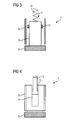
- FIG 1
- eine elektrische Maschine,
- FIG 2
- einen Schnitt durch eine Bürstenanordnung von der Seite ohne Sperrelement,
- FIG 3
- einen Schnitt durch die Bürstenanordnung von
FIG 2 längs einer Linie III-III inFIG 2 , - FIG 4
- eine Draufsicht auf die Bürstenanordnung von
FIG 2 aus einer Richtung IV-IV inFIG 2 , - FIG 5
- die Bürstenanordnung von
FIG 2 mit Sperrelement und - FIG 6
- eine Draufsicht auf die Bürstenanordnung von
FIG 5 aus einer Richtung VI-VI inFIG 5 . - Gemäß
FIG 1 weist eine elektrische Maschine einen Stator 1 und einen Rotor 2 auf. Der Stator 1 kann beispielsweise in einem Gehäuse 3 angeordnet sein. Der Rotor 2 ist in Lagern 4 drehbar gelagert, so dass er um eine Rotationsachse 5 rotierbar ist. Die Lager 4 sind üblicherweise in Lagerschilden angeordnet, die beispielsweise Bestandteil des Gehäuses 3 sein können. - Der Rotor 2 weist (mindestens) einen Schleifring 6 auf. Der Schleifring 6 wirkt mit einer Bürstenanordnung 7 zusammen, die statorfest angeordnet ist. Die Bürstenanordnung 7 kann alternativ am Stator 1 selbst oder am Gehäuse 3 angeordnet sein. Über die Bürstenanordnung 7 und den Schleifring 6 wird ein Strom in den Rotor 2 eingespeist oder ausgespeist.
- Die Bürstenanordnung 7 weist gemäß den
FIG 2 bis 6 einen Bürstenhalter 8 auf, in dem eine Bürste 9 angeordnet ist. Im Betrieb der elektrischen Maschine - siehe dieFIG 2 bis 4 - ist die Bürste 9 im Bürstenhalter 8 beweglich gelagert. Insbesondere wird die Bürste 9 mittels einer Andrückeinrichtung 10 - beispielsweise einer Federeinrichtung - an den Schleifring 6 angedrückt. - Im Laufe des Betriebs der elektrischen Maschine verschleißt die Bürste 9. Um rechtzeitig erkennen zu können, dass die Bürste 9 verschlissen ist, ist der Bürste 9 eine Kontaktanordnung 11 zugeordnet. Die Kontaktanordnung 11 wird, wie allgemein bekannt ist, von der Bürste 9 ausgelöst, wenn die Bürste 9 einen vorbestimmten Verschleißzustand erreicht. Beispielsweise kann an der Bürste 9 gemäß der Darstellung in den
FIG 2 bis 4 ein schwanenhalsähnlicher Ausleger 12 befestigt sein, der sich zusammen mit der Bürste 9 bewegt und einen Hebel 13 betätigt, mittels dessen seinerseits wiederum ein Schalter 14 betätigt wird. Es sind jedoch ebenso andere Gestaltungen möglich. Im Rahmen der in denFIG 2 bis 4 dargestellten konkreten Ausgestaltung weist der Bürstenhalter 8 im Bereich des Auslegers 12 üblicherweise eine Ausnehmung 15 auf, so dass der Ausleger 12 das Andrücken der Bürste 9 an den Schleifring 6 nicht behindert. - Wenn die elektrische Maschine über längere Zeit nicht betrieben werden soll, ist es sinnvoll, die Bürste 9 vom Schleifring 6 abzuheben, um die Gefahr einer Stillstandskorrosion zu vermeiden. Zu diesem Zweck wird die Bürste 9 manuell mit oder ohne Zuhilfenahme eines Werkzeugs gegen eine von der Andrückeinrichtung 10 ausgeübte Andrückkraft F vom Schleifring 6 abgehoben. Sodann wird - siehe die
FIG 5 bis 6 - die Bürste 9 mittels eines Sperrelements 16 fixiert. Die Bürste 9 ist dadurch mittels des Sperrelements 16 dauerhaft gegen die Andrückkraft F vom Schleifring 6 abgehoben. Beispielsweise kann im Rahmen der konkreten Ausgestaltung derFIG 2 bis 6 das Sperrelement 16 einerseits an der Unterkante der Ausnehmung 15 und andererseits an der Unterseite des Auslegers 12 angreifen. Das Sperrelement 16 ist derart ausgelegt, dass es die Kontaktanordnung 11 auslöst. - Soweit es einen reinen Stillstand betrifft, ist das Sperrelement 16 bereits durch die Andrückkraft F gegen selbsttätiges Lösen gesichert. Falls Vibrationen, Schwingungen, Erschütterungen und dergleichen mehr auftreten können, besteht jedoch die Gefahr, dass das Sperrelement 16 sich im Laufe der Zeit verlagert. Die Verlagerung kann so stark sein, dass das Sperrelement 16 abrutscht oder dergleichen, so dass es seinen Zweck nicht mehr erfüllen kann. Vorzugsweise ist daher entsprechend der Darstellung in den
FIG 5 bis 6 das Sperrelement 16 mittels eines Sicherungselements 17 gegen selbsttätiges Lösen gesichert. Das Sicherungselement 17 kann beispielsweise als Kabelbinder ausgebildet sein. - Zusammengefasst betrifft die vorliegende Erfindung folgenden Sachverhalt:
- Eine elektrische Maschine weist einen Stator 1 und einen Rotor 2 auf. Der Rotor 2 ist drehbar gelagert und weist einen Schleifring 6 auf. Statorfest ist eine Bürstenanordnung 7 angeordnet, die einen Bürstenhalter 8 aufweist, in dem eine Bürste 9 angeordnet ist. Die Bürste 9 ist im Betrieb der elektrischen Maschine im Bürstenhalter 8 beweglich gelagert und wird mittels einer Andrückeinrichtung 10 an den Schleifring 6 angedrückt. Der Bürste 9 ist eine Kontaktanordnung 11 zugeordnet, die von der Bürste 9 ausgelöst wird, wenn die Bürste 9 einen vorbestimmten Verschleißzustand erreicht. Die Bürste 9 ist mittels eines Sperrelements 16 gegen eine von der Andrückeinrichtung 10 ausgeübte Andrückkraft F vom Schleifring 6 abgehoben. Das Sperrelement 16 ist derart ausgelegt, dass es die Kontaktanordnung 11 auslöst.
- Die vorliegende Erfindung weist viele Vorteile auf. Insbesondere wird auf einfache und zuverlässige Weise eine Stillstandskorrosion vermieden.
- Obwohl die Erfindung im Detail durch das bevorzugte Ausführungsbeispiel näher illustriert und beschrieben wurde, so ist die Erfindung nicht durch die offenbarten Beispiele eingeschränkt und andere Variationen können vom Fachmann hieraus abgeleitet werden, ohne den Schutzumfang der Erfindung zu verlassen.
Claims (3)
- Elektrische Maschine,- wobei die elektrische Maschine einen Stator (1) und einen Rotor (2) aufweist,- wobei der Rotor (2) drehbar gelagert ist und einen Schleifring (6) aufweist,- wobei statorfest eine Bürstenanordnung (7) angeordnet ist,- wobei die Bürstenanordnung (7) einen Bürstenhalter (8) aufweist, in dem eine Bürste (9) angeordnet ist,- wobei die Bürste (9) im Betrieb der elektrischen Maschine im Bürstenhalter (8) beweglich gelagert und mittels einer Andrückeinrichtung (10) an den Schleifring (6) angedrückt wird,- wobei der Bürste (9) eine Kontaktanordnung (11) zugeordnet ist, die von der Bürste (9) ausgelöst wird, wenn die Bürste (9) einen vorbestimmten Verschleißzustand erreicht,- wobei die Bürste (9) mittels eines Sperrelements (16) gegen eine von der Andrückeinrichtung (10) ausgeübte Andrückkraft (F) vom Schleifring (6) abgehoben ist,- wobei das Sperrelement (16) derart ausgelegt ist, dass es die Kontaktanordnung (11) auslöst.
- Elektrische Maschine nach Anspruch 1, dadurch gekennzeichnet, dass das Sperrelement (16) mittels eines Sicherungselements (17) gegen selbsttätiges Lösen gesichert ist.
- Elektrische Maschine nach Anspruch 2, dadurch gekennzeichnet, dass das Sicherungselement (17) als Kabelbinder ausgebildet ist.
Priority Applications (3)
| Application Number | Priority Date | Filing Date | Title |
|---|---|---|---|
| EP13179916.5A EP2835890B1 (de) | 2013-08-09 | 2013-08-09 | Elektrische Maschine mit gesichertem Abheben der Bürsten bei Stillstand |
| DK13179916.5T DK2835890T3 (en) | 2013-08-09 | 2013-08-09 | Electric machine with secure brush removal |
| ES13179916.5T ES2560841T3 (es) | 2013-08-09 | 2013-08-09 | Máquina eléctrica con elevación de seguridad de las escobillas en caso de parada |
Applications Claiming Priority (1)
| Application Number | Priority Date | Filing Date | Title |
|---|---|---|---|
| EP13179916.5A EP2835890B1 (de) | 2013-08-09 | 2013-08-09 | Elektrische Maschine mit gesichertem Abheben der Bürsten bei Stillstand |
Publications (2)
| Publication Number | Publication Date |
|---|---|
| EP2835890A1 EP2835890A1 (de) | 2015-02-11 |
| EP2835890B1 true EP2835890B1 (de) | 2015-12-30 |
Family
ID=48948330
Family Applications (1)
| Application Number | Title | Priority Date | Filing Date |
|---|---|---|---|
| EP13179916.5A Active EP2835890B1 (de) | 2013-08-09 | 2013-08-09 | Elektrische Maschine mit gesichertem Abheben der Bürsten bei Stillstand |
Country Status (3)
| Country | Link |
|---|---|
| EP (1) | EP2835890B1 (de) |
| DK (1) | DK2835890T3 (de) |
| ES (1) | ES2560841T3 (de) |
Families Citing this family (1)
| Publication number | Priority date | Publication date | Assignee | Title |
|---|---|---|---|---|
| ES2747431T3 (es) * | 2015-05-29 | 2020-03-10 | Siemens Ag | Transmisión giratoria que produce un contacto, para la conducción de energía eléctrica |
Family Cites Families (9)
| Publication number | Priority date | Publication date | Assignee | Title |
|---|---|---|---|---|
| JPS5942547B2 (ja) * | 1978-11-29 | 1984-10-16 | 株式会社日立製作所 | 回転電機のブラシ保持装置 |
| DE8628227U1 (de) | 1986-10-23 | 1987-03-19 | G. Dietrich GmbH Spezialfabrik für Bürstenhalter und Kunststoffteile, 7893 Jestetten | Bürstenhalter mit Bürstenmeldevorrichtung |
| US4739208A (en) * | 1986-11-13 | 1988-04-19 | General Electric Company | Brush assembly including brush wear detector |
| DE9400080U1 (de) | 1993-01-15 | 1994-03-03 | Siemens AG, 80333 München | Trägereinrichtung für eine Bürste |
| DE9410881U1 (de) | 1994-07-07 | 1994-11-17 | Dietrich G Gmbh | Bürstenbrücke für Gleichstrommaschinen |
| DE19619733A1 (de) | 1996-05-15 | 1997-11-20 | Siemens Ag | Steckbürstenhalter sowie eine Einrichtung und ein Verfahren zum Überwachen der Bürste |
| DE19758235A1 (de) | 1997-12-30 | 1999-04-22 | Siemens Ag | Steckbürstenhalteranordnung |
| JP4882189B2 (ja) * | 2001-09-10 | 2012-02-22 | 株式会社Gsユアサ | ブラシ付きモーター |
| DE102007018002A1 (de) * | 2007-04-17 | 2008-10-23 | Robert Bosch Gmbh | Elektromotor |
-
2013
- 2013-08-09 ES ES13179916.5T patent/ES2560841T3/es active Active
- 2013-08-09 EP EP13179916.5A patent/EP2835890B1/de active Active
- 2013-08-09 DK DK13179916.5T patent/DK2835890T3/en active
Also Published As
| Publication number | Publication date |
|---|---|
| ES2560841T3 (es) | 2016-02-23 |
| DK2835890T3 (en) | 2016-03-14 |
| EP2835890A1 (de) | 2015-02-11 |
Similar Documents
| Publication | Publication Date | Title |
|---|---|---|
| DE102008002548B4 (de) | Werkzeugmaschine, insbesondere Handwerkzeugmaschine | |
| EP2020280A2 (de) | Abdeckvorrichtung eines Werkzeuggerätes | |
| EP3261788B1 (de) | Giesseinrichtung mit halterung eines schattenrohres am pfannenverschluss | |
| EP3224001B1 (de) | Selbstsperrende veriegelung einer adaptervorrichtung | |
| EP2278177B1 (de) | Verliersicherung mit einer Schraube und Schutzeinrichtung für ein Maschinenteil | |
| WO2009047083A1 (de) | Bürstenanordnung und elektrische maschine, insbesondere elektrisches hausgerät | |
| EP2835890A1 (de) | Elektrische Maschine mit gesichertem Abheben der Bürsten bei Stillstand | |
| DE2244226A1 (de) | Werkzeughalter | |
| EP3794685B1 (de) | Elektrischer winkelsteckverbinder | |
| EP2907935B1 (de) | Rückhaltevorrichtung, insbesondere für attikagullys | |
| WO2017108024A1 (de) | Kraftfahrzeugschloss mit drehfallenabstützung | |
| WO2016074963A1 (de) | Zylinderanordnung mit einstellbarem anschlag | |
| EP2343386B1 (de) | Spülstein Ein- und Ausbauwerkzeug | |
| EP2413341B1 (de) | Drucktaster mit mechanischer Signalanzeige | |
| EP3388154A1 (de) | Malerwalze | |
| EP1593139B1 (de) | Elektromagnetischer leistungsschalter | |
| EP3137260B1 (de) | Spannbolzen und spannvorrichtung mit einem solchen spannbolzen | |
| WO2021121785A1 (de) | Not-halt-schalter und maschine mit not-halt-schalter | |
| DE102012200296B4 (de) | Drehregler für ein Haushaltsgerät und Kochgerät mit Drehregler | |
| DE102016200149B4 (de) | Vorrichtung zum Spannen von Werkstücken | |
| DE7404456U (de) | Vorrichtung zum Abschalten der Bürsten elektrischer Maschinen | |
| DE102010032832B4 (de) | Abdrückvorrichtung und Behältnis mit einer solchen | |
| DE102016010478B4 (de) | Scherzylinder mit Nuten | |
| DE102017202056A1 (de) | Filtereinrichtung | |
| WO2018103790A1 (de) | Kraftfahrzeugtürschloss |
Legal Events
| Date | Code | Title | Description |
|---|---|---|---|
| PUAI | Public reference made under article 153(3) epc to a published international application that has entered the european phase |
Free format text: ORIGINAL CODE: 0009012 |
|
| 17P | Request for examination filed |
Effective date: 20140718 |
|
| AK | Designated contracting states |
Kind code of ref document: A1 Designated state(s): AL AT BE BG CH CY CZ DE DK EE ES FI FR GB GR HR HU IE IS IT LI LT LU LV MC MK MT NL NO PL PT RO RS SE SI SK SM TR |
|
| AX | Request for extension of the european patent |
Extension state: BA ME |
|
| RIC1 | Information provided on ipc code assigned before grant |
Ipc: H02K 5/14 20060101AFI20150522BHEP Ipc: H01R 39/59 20060101ALI20150522BHEP |
|
| GRAP | Despatch of communication of intention to grant a patent |
Free format text: ORIGINAL CODE: EPIDOSNIGR1 |
|
| INTG | Intention to grant announced |
Effective date: 20150702 |
|
| RIN1 | Information on inventor provided before grant (corrected) |
Inventor name: MEMMINGER, OLIVER Inventor name: BINDER, HERBERT Inventor name: VOGES, MICHAEL Inventor name: RINGLEB, ULRICH, DR. |
|
| GRAS | Grant fee paid |
Free format text: ORIGINAL CODE: EPIDOSNIGR3 |
|
| GRAA | (expected) grant |
Free format text: ORIGINAL CODE: 0009210 |
|
| AK | Designated contracting states |
Kind code of ref document: B1 Designated state(s): AL AT BE BG CH CY CZ DE DK EE ES FI FR GB GR HR HU IE IS IT LI LT LU LV MC MK MT NL NO PL PT RO RS SE SI SK SM TR |
|
| REG | Reference to a national code |
Ref country code: GB Ref legal event code: FG4D Free format text: NOT ENGLISH |
|
| REG | Reference to a national code |
Ref country code: CH Ref legal event code: EP |
|
| REG | Reference to a national code |
Ref country code: AT Ref legal event code: REF Ref document number: 767868 Country of ref document: AT Kind code of ref document: T Effective date: 20160115 |
|
| REG | Reference to a national code |
Ref country code: IE Ref legal event code: FG4D Free format text: LANGUAGE OF EP DOCUMENT: GERMAN |
|
| REG | Reference to a national code |
Ref country code: DE Ref legal event code: R096 Ref document number: 502013001681 Country of ref document: DE |
|
| REG | Reference to a national code |
Ref country code: ES Ref legal event code: FG2A Ref document number: 2560841 Country of ref document: ES Kind code of ref document: T3 Effective date: 20160223 |
|
| REG | Reference to a national code |
Ref country code: DK Ref legal event code: T3 Effective date: 20160310 |
|
| REG | Reference to a national code |
Ref country code: NL Ref legal event code: FP |
|
| REG | Reference to a national code |
Ref country code: LT Ref legal event code: MG4D |
|
| REG | Reference to a national code |
Ref country code: SE Ref legal event code: TRGR |
|
| PG25 | Lapsed in a contracting state [announced via postgrant information from national office to epo] |
Ref country code: LT Free format text: LAPSE BECAUSE OF FAILURE TO SUBMIT A TRANSLATION OF THE DESCRIPTION OR TO PAY THE FEE WITHIN THE PRESCRIBED TIME-LIMIT Effective date: 20151230 Ref country code: HR Free format text: LAPSE BECAUSE OF FAILURE TO SUBMIT A TRANSLATION OF THE DESCRIPTION OR TO PAY THE FEE WITHIN THE PRESCRIBED TIME-LIMIT Effective date: 20151230 |
|
| REG | Reference to a national code |
Ref country code: NO Ref legal event code: T2 Effective date: 20151230 |
|
| PG25 | Lapsed in a contracting state [announced via postgrant information from national office to epo] |
Ref country code: GR Free format text: LAPSE BECAUSE OF FAILURE TO SUBMIT A TRANSLATION OF THE DESCRIPTION OR TO PAY THE FEE WITHIN THE PRESCRIBED TIME-LIMIT Effective date: 20160331 Ref country code: RS Free format text: LAPSE BECAUSE OF FAILURE TO SUBMIT A TRANSLATION OF THE DESCRIPTION OR TO PAY THE FEE WITHIN THE PRESCRIBED TIME-LIMIT Effective date: 20151230 Ref country code: LV Free format text: LAPSE BECAUSE OF FAILURE TO SUBMIT A TRANSLATION OF THE DESCRIPTION OR TO PAY THE FEE WITHIN THE PRESCRIBED TIME-LIMIT Effective date: 20151230 |
|
| PG25 | Lapsed in a contracting state [announced via postgrant information from national office to epo] |
Ref country code: CZ Free format text: LAPSE BECAUSE OF FAILURE TO SUBMIT A TRANSLATION OF THE DESCRIPTION OR TO PAY THE FEE WITHIN THE PRESCRIBED TIME-LIMIT Effective date: 20151230 |
|
| REG | Reference to a national code |
Ref country code: FR Ref legal event code: PLFP Year of fee payment: 4 |
|
| PG25 | Lapsed in a contracting state [announced via postgrant information from national office to epo] |
Ref country code: PL Free format text: LAPSE BECAUSE OF FAILURE TO SUBMIT A TRANSLATION OF THE DESCRIPTION OR TO PAY THE FEE WITHIN THE PRESCRIBED TIME-LIMIT Effective date: 20151230 Ref country code: EE Free format text: LAPSE BECAUSE OF FAILURE TO SUBMIT A TRANSLATION OF THE DESCRIPTION OR TO PAY THE FEE WITHIN THE PRESCRIBED TIME-LIMIT Effective date: 20151230 Ref country code: SM Free format text: LAPSE BECAUSE OF FAILURE TO SUBMIT A TRANSLATION OF THE DESCRIPTION OR TO PAY THE FEE WITHIN THE PRESCRIBED TIME-LIMIT Effective date: 20151230 Ref country code: SK Free format text: LAPSE BECAUSE OF FAILURE TO SUBMIT A TRANSLATION OF THE DESCRIPTION OR TO PAY THE FEE WITHIN THE PRESCRIBED TIME-LIMIT Effective date: 20151230 Ref country code: PT Free format text: LAPSE BECAUSE OF FAILURE TO SUBMIT A TRANSLATION OF THE DESCRIPTION OR TO PAY THE FEE WITHIN THE PRESCRIBED TIME-LIMIT Effective date: 20160502 Ref country code: IS Free format text: LAPSE BECAUSE OF FAILURE TO SUBMIT A TRANSLATION OF THE DESCRIPTION OR TO PAY THE FEE WITHIN THE PRESCRIBED TIME-LIMIT Effective date: 20160430 Ref country code: RO Free format text: LAPSE BECAUSE OF FAILURE TO SUBMIT A TRANSLATION OF THE DESCRIPTION OR TO PAY THE FEE WITHIN THE PRESCRIBED TIME-LIMIT Effective date: 20151230 |
|
| REG | Reference to a national code |
Ref country code: DE Ref legal event code: R097 Ref document number: 502013001681 Country of ref document: DE |
|
| PLBE | No opposition filed within time limit |
Free format text: ORIGINAL CODE: 0009261 |
|
| STAA | Information on the status of an ep patent application or granted ep patent |
Free format text: STATUS: NO OPPOSITION FILED WITHIN TIME LIMIT |
|
| 26N | No opposition filed |
Effective date: 20161003 |
|
| PG25 | Lapsed in a contracting state [announced via postgrant information from national office to epo] |
Ref country code: BE Free format text: LAPSE BECAUSE OF NON-PAYMENT OF DUE FEES Effective date: 20160831 |
|
| PG25 | Lapsed in a contracting state [announced via postgrant information from national office to epo] |
Ref country code: SI Free format text: LAPSE BECAUSE OF FAILURE TO SUBMIT A TRANSLATION OF THE DESCRIPTION OR TO PAY THE FEE WITHIN THE PRESCRIBED TIME-LIMIT Effective date: 20151230 |
|
| PG25 | Lapsed in a contracting state [announced via postgrant information from national office to epo] |
Ref country code: MC Free format text: LAPSE BECAUSE OF FAILURE TO SUBMIT A TRANSLATION OF THE DESCRIPTION OR TO PAY THE FEE WITHIN THE PRESCRIBED TIME-LIMIT Effective date: 20151230 |
|
| REG | Reference to a national code |
Ref country code: CH Ref legal event code: PL |
|
| PG25 | Lapsed in a contracting state [announced via postgrant information from national office to epo] |
Ref country code: LI Free format text: LAPSE BECAUSE OF NON-PAYMENT OF DUE FEES Effective date: 20160831 Ref country code: CH Free format text: LAPSE BECAUSE OF NON-PAYMENT OF DUE FEES Effective date: 20160831 |
|
| REG | Reference to a national code |
Ref country code: IE Ref legal event code: MM4A |
|
| PG25 | Lapsed in a contracting state [announced via postgrant information from national office to epo] |
Ref country code: IE Free format text: LAPSE BECAUSE OF NON-PAYMENT OF DUE FEES Effective date: 20160809 |
|
| REG | Reference to a national code |
Ref country code: FR Ref legal event code: PLFP Year of fee payment: 5 |
|
| PG25 | Lapsed in a contracting state [announced via postgrant information from national office to epo] |
Ref country code: LU Free format text: LAPSE BECAUSE OF NON-PAYMENT OF DUE FEES Effective date: 20160809 |
|
| PG25 | Lapsed in a contracting state [announced via postgrant information from national office to epo] |
Ref country code: HU Free format text: LAPSE BECAUSE OF FAILURE TO SUBMIT A TRANSLATION OF THE DESCRIPTION OR TO PAY THE FEE WITHIN THE PRESCRIBED TIME-LIMIT; INVALID AB INITIO Effective date: 20130809 |
|
| PG25 | Lapsed in a contracting state [announced via postgrant information from national office to epo] |
Ref country code: CY Free format text: LAPSE BECAUSE OF FAILURE TO SUBMIT A TRANSLATION OF THE DESCRIPTION OR TO PAY THE FEE WITHIN THE PRESCRIBED TIME-LIMIT Effective date: 20151230 Ref country code: MT Free format text: LAPSE BECAUSE OF FAILURE TO SUBMIT A TRANSLATION OF THE DESCRIPTION OR TO PAY THE FEE WITHIN THE PRESCRIBED TIME-LIMIT Effective date: 20151230 Ref country code: MK Free format text: LAPSE BECAUSE OF FAILURE TO SUBMIT A TRANSLATION OF THE DESCRIPTION OR TO PAY THE FEE WITHIN THE PRESCRIBED TIME-LIMIT Effective date: 20151230 |
|
| PG25 | Lapsed in a contracting state [announced via postgrant information from national office to epo] |
Ref country code: BG Free format text: LAPSE BECAUSE OF FAILURE TO SUBMIT A TRANSLATION OF THE DESCRIPTION OR TO PAY THE FEE WITHIN THE PRESCRIBED TIME-LIMIT Effective date: 20151230 |
|
| REG | Reference to a national code |
Ref country code: FR Ref legal event code: PLFP Year of fee payment: 6 |
|
| PG25 | Lapsed in a contracting state [announced via postgrant information from national office to epo] |
Ref country code: TR Free format text: LAPSE BECAUSE OF FAILURE TO SUBMIT A TRANSLATION OF THE DESCRIPTION OR TO PAY THE FEE WITHIN THE PRESCRIBED TIME-LIMIT Effective date: 20151230 Ref country code: AL Free format text: LAPSE BECAUSE OF FAILURE TO SUBMIT A TRANSLATION OF THE DESCRIPTION OR TO PAY THE FEE WITHIN THE PRESCRIBED TIME-LIMIT Effective date: 20151230 |
|
| REG | Reference to a national code |
Ref country code: AT Ref legal event code: MM01 Ref document number: 767868 Country of ref document: AT Kind code of ref document: T Effective date: 20180809 |
|
| PG25 | Lapsed in a contracting state [announced via postgrant information from national office to epo] |
Ref country code: AT Free format text: LAPSE BECAUSE OF NON-PAYMENT OF DUE FEES Effective date: 20180809 |
|
| REG | Reference to a national code |
Ref country code: DE Ref legal event code: R081 Ref document number: 502013001681 Country of ref document: DE Owner name: FLENDER GMBH, DE Free format text: FORMER OWNER: SIEMENS AKTIENGESELLSCHAFT, 80333 MUENCHEN, DE |
|
| REG | Reference to a national code |
Ref country code: FI Ref legal event code: PCE Owner name: FLENDER GMBH |
|
| REG | Reference to a national code |
Ref country code: NL Ref legal event code: PD Owner name: FLENDER GMBH; DE Free format text: DETAILS ASSIGNMENT: CHANGE OF OWNER(S), ASSIGNMENT; FORMER OWNER NAME: SIEMENS AKTIENGESELLSCHAFT Effective date: 20201208 |
|
| REG | Reference to a national code |
Ref country code: NO Ref legal event code: CHAD Owner name: FLENDER GMBH, DE |
|
| REG | Reference to a national code |
Ref country code: GB Ref legal event code: 732E Free format text: REGISTERED BETWEEN 20201210 AND 20201216 |
|
| REG | Reference to a national code |
Ref country code: ES Ref legal event code: PC2A Owner name: FLENDER GMBH Effective date: 20210223 |
|
| REG | Reference to a national code |
Ref country code: DE Ref legal event code: R082 Ref document number: 502013001681 Country of ref document: DE Representative=s name: MICHALSKI HUETTERMANN & PARTNER PATENTANWAELTE, DE |
|
| PGFP | Annual fee paid to national office [announced via postgrant information from national office to epo] |
Ref country code: NL Payment date: 20220822 Year of fee payment: 10 |
|
| PGFP | Annual fee paid to national office [announced via postgrant information from national office to epo] |
Ref country code: SE Payment date: 20220819 Year of fee payment: 10 Ref country code: NO Payment date: 20220824 Year of fee payment: 10 Ref country code: IT Payment date: 20220825 Year of fee payment: 10 Ref country code: FI Payment date: 20220822 Year of fee payment: 10 |
|
| PGFP | Annual fee paid to national office [announced via postgrant information from national office to epo] |
Ref country code: FR Payment date: 20220823 Year of fee payment: 10 |
|
| PGFP | Annual fee paid to national office [announced via postgrant information from national office to epo] |
Ref country code: DK Payment date: 20230823 Year of fee payment: 11 |
|
| REG | Reference to a national code |
Ref country code: NL Ref legal event code: MM Effective date: 20230901 |
|
| PG25 | Lapsed in a contracting state [announced via postgrant information from national office to epo] |
Ref country code: FI Free format text: LAPSE BECAUSE OF NON-PAYMENT OF DUE FEES Effective date: 20230809 |
|
| PG25 | Lapsed in a contracting state [announced via postgrant information from national office to epo] |
Ref country code: NL Free format text: LAPSE BECAUSE OF NON-PAYMENT OF DUE FEES Effective date: 20230901 |
|
| PG25 | Lapsed in a contracting state [announced via postgrant information from national office to epo] |
Ref country code: SE Free format text: LAPSE BECAUSE OF NON-PAYMENT OF DUE FEES Effective date: 20230810 Ref country code: NO Free format text: LAPSE BECAUSE OF NON-PAYMENT OF DUE FEES Effective date: 20230831 Ref country code: NL Free format text: LAPSE BECAUSE OF NON-PAYMENT OF DUE FEES Effective date: 20230901 |
|
| PG25 | Lapsed in a contracting state [announced via postgrant information from national office to epo] |
Ref country code: IT Free format text: LAPSE BECAUSE OF NON-PAYMENT OF DUE FEES Effective date: 20230809 Ref country code: FR Free format text: LAPSE BECAUSE OF NON-PAYMENT OF DUE FEES Effective date: 20230831 |
|
| REG | Reference to a national code |
Ref country code: DK Ref legal event code: EBP Effective date: 20240831 |
|
| PG25 | Lapsed in a contracting state [announced via postgrant information from national office to epo] |
Ref country code: DK Free format text: LAPSE BECAUSE OF NON-PAYMENT OF DUE FEES Effective date: 20240831 |
|
| PGFP | Annual fee paid to national office [announced via postgrant information from national office to epo] |
Ref country code: ES Payment date: 20250926 Year of fee payment: 13 |
|
| PGFP | Annual fee paid to national office [announced via postgrant information from national office to epo] |
Ref country code: DE Payment date: 20250827 Year of fee payment: 13 |
|
| PGFP | Annual fee paid to national office [announced via postgrant information from national office to epo] |
Ref country code: GB Payment date: 20250820 Year of fee payment: 13 |