EP2835548A1 - Agencement d'embrayage, notamment pour un embrayage à friction dans un système de débrayage d'un véhicule automobile - Google Patents
Agencement d'embrayage, notamment pour un embrayage à friction dans un système de débrayage d'un véhicule automobile Download PDFInfo
- Publication number
- EP2835548A1 EP2835548A1 EP20130002813 EP13002813A EP2835548A1 EP 2835548 A1 EP2835548 A1 EP 2835548A1 EP 20130002813 EP20130002813 EP 20130002813 EP 13002813 A EP13002813 A EP 13002813A EP 2835548 A1 EP2835548 A1 EP 2835548A1
- Authority
- EP
- European Patent Office
- Prior art keywords
- bearing
- cover
- clutch
- coupling arrangement
- arrangement according
- Prior art date
- Legal status (The legal status is an assumption and is not a legal conclusion. Google has not performed a legal analysis and makes no representation as to the accuracy of the status listed.)
- Withdrawn
Links
Images

Classifications
-
- C—CHEMISTRY; METALLURGY
- C09—DYES; PAINTS; POLISHES; NATURAL RESINS; ADHESIVES; COMPOSITIONS NOT OTHERWISE PROVIDED FOR; APPLICATIONS OF MATERIALS NOT OTHERWISE PROVIDED FOR
- C09C—TREATMENT OF INORGANIC MATERIALS, OTHER THAN FIBROUS FILLERS, TO ENHANCE THEIR PIGMENTING OR FILLING PROPERTIES ; PREPARATION OF CARBON BLACK ; PREPARATION OF INORGANIC MATERIALS WHICH ARE NO SINGLE CHEMICAL COMPOUNDS AND WHICH ARE MAINLY USED AS PIGMENTS OR FILLERS
- C09C1/00—Treatment of specific inorganic materials other than fibrous fillers; Preparation of carbon black
- C09C1/36—Compounds of titanium
- C09C1/3607—Titanium dioxide
- C09C1/3653—Treatment with inorganic compounds
-
- F—MECHANICAL ENGINEERING; LIGHTING; HEATING; WEAPONS; BLASTING
- F16—ENGINEERING ELEMENTS AND UNITS; GENERAL MEASURES FOR PRODUCING AND MAINTAINING EFFECTIVE FUNCTIONING OF MACHINES OR INSTALLATIONS; THERMAL INSULATION IN GENERAL
- F16D—COUPLINGS FOR TRANSMITTING ROTATION; CLUTCHES; BRAKES
- F16D25/00—Fluid-actuated clutches
- F16D25/08—Fluid-actuated clutches with fluid-actuated member not rotating with a clutching member
- F16D25/082—Fluid-actuated clutches with fluid-actuated member not rotating with a clutching member the line of action of the fluid-actuated members co-inciding with the axis of rotation
- F16D25/087—Fluid-actuated clutches with fluid-actuated member not rotating with a clutching member the line of action of the fluid-actuated members co-inciding with the axis of rotation the clutch being actuated by the fluid-actuated member via a diaphragm spring or an equivalent array of levers
-
- C—CHEMISTRY; METALLURGY
- C01—INORGANIC CHEMISTRY
- C01P—INDEXING SCHEME RELATING TO STRUCTURAL AND PHYSICAL ASPECTS OF SOLID INORGANIC COMPOUNDS
- C01P2004/00—Particle morphology
- C01P2004/01—Particle morphology depicted by an image
- C01P2004/03—Particle morphology depicted by an image obtained by SEM
Definitions
- the invention relates to a clutch assembly, in particular for a friction clutch in a clutch release system of a motor vehicle, comprising a slave cylinder with a housing and a guide sleeve, which enclose an annular pressure chamber in which a piston is mounted axially movable, which is fixedly connected to a release bearing, which a plate spring in the axial direction acted upon by a force, wherein a cover bearing is fixedly connected to a clutch cover.
- clutch systems are used to separate or establish the adhesion between an engine and a transmission.
- a release system for example a slave cylinder designed as a hydraulic cylinder
- a hydraulic clutch actuation device in the direction of a disengagement element, for example a clutch disc, whereby the clutch is closed.
- Release systems transmit forces that lead due to a depressed clutch pedal or a signal control electronics to interrupt the flow of torque between the built-in motor vehicle engine and the transmission.
- a friction clutch which is equipped with a clutch release device comprising a slave cylinder with a housing which is connected by means of a cover bearing rotatably and axially fixed to a mounting flange of the friction clutch.
- a guide sleeve surrounds an annular pressure chamber, in which an axially displaceable annular piston is arranged, which is axially fixedly connected to a release bearing, which acts on a radially inner portion of a plate spring in the axial direction with force.
- the invention is therefore based on the object to provide a clutch assembly which requires only a very small radial space and can be used for longitudinal and transverse applications of the engine.
- the object is achieved in that the cover bearing is axially spaced from the slave cylinder mounted in the direction of coupling, wherein the clutch cover is guided between the cover bearing and the release bearing and in particular the plate spring between the cover bearing and the release bearing.
- This embodiment eliminates the use of an additional sheet metal flange, which has the advantage that the radial space for the clutch assembly is substantially reduced.
- the clutch cover covering the cover bearing is guided inwardly towards the clutch near a gear shaft comprised by the slave cylinder.
- the cover bearing can be made much smaller. The cost of a new cover bearing is reduced and is comparable to the cost of a release bearing.
- the releasing bearing in contact with the tongues of the plate spring is arranged axially between the cover bearing and the slave cylinder. Only the cover bearing is covered by the clutch cover, whereby the space for the clutch cover is reduced.
- the cover bearing is centered on an end stop of the coupling for the tongues of the diaphragm spring.
- components which are present in the coupling are used for centering the cover bearing and additional components for centering the cover bearing are dispensed with.
- additional components for centering the cover bearing reduces the manufacturing cost of the clutch assembly.
- the cover bearing can be realized in many forms.
- the cover bearing can be designed as angular contact ball bearings or as deep groove ball bearings or as axial needle roller bearings or as axial ball bearings.
- the proposed clutch assembly is thus applicable to a wide variety of cover bearings.
- the cover bearing is arranged on the reinforced guide sleeve, which engages around the housing of the slave cylinder, in particular with a flange.
- the order of several Millimeter reinforced guide sleeve thus serves as a support for the cover bearing near the clutch.
- the housing has a radially arranged seal, which seals the housing against the guide sleeve. This radial seal ensures that each time the coupling is actuated, the housing made of plastic is always pressed in the direction of the flange of the guide sleeve. In addition to a secure seal of the pressure chamber, the connection between the guide sleeve and housing is stabilized at a pressurization.
- the guide sleeve has a groove in which a snap ring engages.
- the snap ring serves to produce the mechanical connection between the clutch and the slave cylinder. This mechanical connection is very easy to produce and stable against a force.
- the groove is formed on the side facing away from the flange of the guide sleeve, wherein in particular the snap ring engages a bearing shoulder of an inner ring of the cover bearing.
- a preload spring exerts a force on the cover bearing, wherein the preload spring is preferably arranged between the housing and the release bearing.
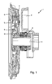
- FIG. 1 shows a first embodiment of the clutch assembly according to the invention 1.
- the clutch assembly 1 is covered with a clutch bell 2.
- the clutch assembly 1 has a slave cylinder 3, which extends rotationally symmetrical about a transmission shaft 4.
- the slave cylinder 3 presses on the tongues of a plate spring 5, which are connected to the coupling 6.
- the tongues of the disc spring 5 are passed through an opening 8 of the clutch cover 7, which bears with its end against a cover bearing 9 which is formed near the coupling 6.
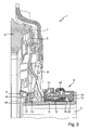
- the coupling assembly 1 is shown in a section.
- the slave cylinder 3 has a housing 10 which is mounted on a guide sleeve 11, wherein the guide sleeve 11 has a flange 12 which comprises the housing 10.
- a pressure chamber 13 Between the housing 10 and the guide sleeve 11 extends a pressure chamber 13, in which an axially movably mounted piston 14 is guided.
- the piston 14 is fixedly connected to a release bearing 15, which acts on a radially inner portion of the plate spring 5 in the axial direction with a force.
- the release bearing 15 is thereby pressed by a preload spring 16 axially against the tongues of the plate spring 5, wherein the preload spring 16 is mounted between the release bearing 15 and the housing 10 of the slave cylinder 3.
- the existing plastic housing 10 also has a radially mounted seal 22, which seals the housing 10 relative to the guide sleeve 11 radially on the pressure chamber 13. This ensures that the housing 10 is always pressed in the direction of the flange 12 of the guide sleeve 11 upon actuation of the coupling. At the same time a reliable sealing of the pressure chamber 13 is realized.
- the slave cylinder 3 has a reinforced guide sleeve 11, which is formed of a metal and has a thickness of about 3 mm.
- the guide sleeve 11th Compared to attacking forces much more stable than guide sleeves according to the prior art, the strength amounts to only 1 mm.
- the guide sleeve 11 is extended to the vicinity of the coupling 6 and has a groove 23 in which a snap ring 17 engages perpendicular to the guide sleeve 11. This snap ring 17 is mounted on the bearing shoulder of the inner ring 18 of the cover bearing 9.
- the cover bearing 9 is supported on the coupling 6 and is centered on the end stop 19 of the coupling 6 for the tongues of the plate spring 5 and placed.
- the cover bearing 9 may be formed in various embodiments.
- a helical or a deep groove ball bearing are just as conceivable as an axial needle roller bearing or an axial ball bearing.
- the snap ring 17 serves to establish the connection between the clutch 6 and the slave cylinder 3. This is done in a very simple manner in that it engages in the groove 23 of the guide sleeve 11.
- the cover bearing 9 only has to be placed, the slave cylinder 3 is inserted into the coupling 6 and used to complete the snap ring 17.
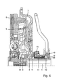
- FIG. 4 a second embodiment of the clutch assembly 1 is shown, which is from the FIG. 2 differs that the flange 12 of the guide sleeve 11 and the snap ring 17 are interchanged.
- the flange 12 protrudes near the clutch 6 approximately parallel to this in the interior of the clutch assembly 1, while the snap ring 17 fixes the housing 10.
- the seal 22 is arranged radially between the housing 10 and the guide sleeve 11 in front of the snap ring 17 in order to prevent separation of the housing 10 and the guide sleeve 11. All other components are related to FIG. 2 explained arrangement unchanged.
- the proposed clutch assembly 1 has a reduced radial size, since the cover bearing 9 and the clutch cover 7 require a smaller space. This not only leads to an increase in the variety of applications of the clutch assembly in motor vehicles with engines that are used as a longitudinal or transverse application, but also reduces the cost of manufacturing significantly.
Landscapes
- Chemical & Material Sciences (AREA)
- Organic Chemistry (AREA)
- Engineering & Computer Science (AREA)
- General Engineering & Computer Science (AREA)
- Mechanical Engineering (AREA)
- Mechanical Operated Clutches (AREA)
Priority Applications (1)
| Application Number | Priority Date | Filing Date | Title |
|---|---|---|---|
| EP20130002813 EP2835548A1 (fr) | 2013-08-08 | 2013-08-08 | Agencement d'embrayage, notamment pour un embrayage à friction dans un système de débrayage d'un véhicule automobile |
Applications Claiming Priority (1)
| Application Number | Priority Date | Filing Date | Title |
|---|---|---|---|
| EP20130002813 EP2835548A1 (fr) | 2013-08-08 | 2013-08-08 | Agencement d'embrayage, notamment pour un embrayage à friction dans un système de débrayage d'un véhicule automobile |
Publications (1)
| Publication Number | Publication Date |
|---|---|
| EP2835548A1 true EP2835548A1 (fr) | 2015-02-11 |
Family
ID=52183102
Family Applications (1)
| Application Number | Title | Priority Date | Filing Date |
|---|---|---|---|
| EP20130002813 Withdrawn EP2835548A1 (fr) | 2013-08-08 | 2013-08-08 | Agencement d'embrayage, notamment pour un embrayage à friction dans un système de débrayage d'un véhicule automobile |
Country Status (1)
| Country | Link |
|---|---|
| EP (1) | EP2835548A1 (fr) |
Cited By (2)
| Publication number | Priority date | Publication date | Assignee | Title |
|---|---|---|---|---|
| CN109996971A (zh) * | 2016-10-13 | 2019-07-09 | Zf腓特烈斯哈芬股份公司 | 用于离合器执行器的控制壳体 |
| WO2019238157A1 (fr) * | 2018-06-12 | 2019-12-19 | Schaeffler Technologies AG & Co. KG | Cylindre récepteur d'embrayage de véhicule automobile comprenant une bride en acier et une partie de limitation d'espace de pression comprenant du plastique, et embrayage de véhicule automobile |
Citations (4)
| Publication number | Priority date | Publication date | Assignee | Title |
|---|---|---|---|---|
| DE19724836A1 (de) * | 1997-06-12 | 1998-12-17 | Schaeffler Waelzlager Ohg | Nehmerzylinder, dessen Leitungsanschluß abgedichtet durch eine Öffnung des Kupplungsgehäuses geführt ist |
| DE102008004150A1 (de) * | 2007-01-31 | 2008-08-07 | Luk Lamellen Und Kupplungsbau Beteiligungs Kg | Drehmomentübertragungseinrichtung |
| DE102008021161A1 (de) | 2007-05-18 | 2008-11-20 | Luk Lamellen Und Kupplungsbau Beteiligungs Kg | Reibungskupplung |
| DE102012203597A1 (de) * | 2011-03-30 | 2012-10-04 | Borgwarner Inc. | Nasskupplungsmodul mit integriertem Wärmetauscher |
-
2013
- 2013-08-08 EP EP20130002813 patent/EP2835548A1/fr not_active Withdrawn
Patent Citations (4)
| Publication number | Priority date | Publication date | Assignee | Title |
|---|---|---|---|---|
| DE19724836A1 (de) * | 1997-06-12 | 1998-12-17 | Schaeffler Waelzlager Ohg | Nehmerzylinder, dessen Leitungsanschluß abgedichtet durch eine Öffnung des Kupplungsgehäuses geführt ist |
| DE102008004150A1 (de) * | 2007-01-31 | 2008-08-07 | Luk Lamellen Und Kupplungsbau Beteiligungs Kg | Drehmomentübertragungseinrichtung |
| DE102008021161A1 (de) | 2007-05-18 | 2008-11-20 | Luk Lamellen Und Kupplungsbau Beteiligungs Kg | Reibungskupplung |
| DE102012203597A1 (de) * | 2011-03-30 | 2012-10-04 | Borgwarner Inc. | Nasskupplungsmodul mit integriertem Wärmetauscher |
Cited By (3)
| Publication number | Priority date | Publication date | Assignee | Title |
|---|---|---|---|---|
| CN109996971A (zh) * | 2016-10-13 | 2019-07-09 | Zf腓特烈斯哈芬股份公司 | 用于离合器执行器的控制壳体 |
| WO2019238157A1 (fr) * | 2018-06-12 | 2019-12-19 | Schaeffler Technologies AG & Co. KG | Cylindre récepteur d'embrayage de véhicule automobile comprenant une bride en acier et une partie de limitation d'espace de pression comprenant du plastique, et embrayage de véhicule automobile |
| CN112262269A (zh) * | 2018-06-12 | 2021-01-22 | 舍弗勒技术股份两合公司 | 包含钢制法兰和塑料包围压力腔限定部件的机动车离合从动缸,以及一种机动车离合器 |
Similar Documents
| Publication | Publication Date | Title |
|---|---|---|
| DE102010060889B4 (de) | Synchronisiervorrichtung für ein Getriebe | |
| EP3212955B1 (fr) | Frein à disque pour un véhicule utilitaire | |
| DE102010060890B4 (de) | Synchronisiervorrichtung für ein Getriebe | |
| EP3078873B1 (fr) | Assemblage de raccordement avec un adaptateur a raccorder a une conduite de fluide sur un boitier de cylindre recepteur ou emetteur | |
| EP1365167B1 (fr) | Dispositif d'actionnement pour embrayage à friction pour véhicule automobile | |
| DE102013209995A1 (de) | Kupplungsanordnung, insbesondere für eine Reibungskupplung in einem Kupplungsausrücksystem eines Kraftfahrzeuges | |
| DE102010043595A1 (de) | Lagerung einer Getriebewelle | |
| EP2924311B1 (fr) | Butée hydraulique pour un dispositif d'actionnement d'embrayage hydraulique ou pneumatique, en particulier pour un véhicule automobile | |
| EP2835548A1 (fr) | Agencement d'embrayage, notamment pour un embrayage à friction dans un système de débrayage d'un véhicule automobile | |
| DE102013218116A1 (de) | Kolben-Zylinder-Anordnung und Verfahren zur Herstellung einer Kolben-Zylinder-Anordnung | |
| DE102011100903B4 (de) | Hydraulisches Kupplungs- oder Bremsbetätigungssystem | |
| EP3177844B1 (fr) | Maître-cylindre comprenant une douille de guidage pour une lèvre d'étanchéité du système de dilatation | |
| DE102011106460A1 (de) | Nehmerzylinder | |
| DE102015211831A1 (de) | Ausrücksystem für ein Kupplungsbetätigungssystem, insbesondere mit einer pneumatischen Übertragungsstrecke | |
| EP3155280A1 (fr) | Maître-cylindre destiné à un système de débrayage | |
| DE102015201643A1 (de) | Hydraulikzylinder für ein Kupplungsbetätigungssystem oder Bremsbetätigungssystem mit einem Wegmesssystem | |
| DE102009014474A1 (de) | Nehmerzylinder | |
| WO2015058760A2 (fr) | Ensemble piston-cylindre, notamment pour un dispositif de commande d'embrayage d'un véhicule à moteur | |
| DE102014212193A1 (de) | Kupplungsausrücksystem | |
| EP2772625B1 (fr) | Système d'entraînement de groupe de moteur à combustion | |
| DE102011087101A1 (de) | Ausrücksystem zur hydraulischen Betätigung einer Kupplung | |
| DE102006036012B4 (de) | Kupplungsvorrichtung, insbesondere Kraftfahrzeug-Kupplungsvorrichtung | |
| DE102011016004B4 (de) | Zentraleinrücker mit zwei Teileinrücksystemen zur Betätigung einer Reibungskupplung von Fahrzeugen | |
| DE102017219821A1 (de) | Kupplungsausrücklagervorrichtung | |
| DE102012221225A1 (de) | Kolbeneinheit für einen hydraulischen Zentralrücker |
Legal Events
| Date | Code | Title | Description |
|---|---|---|---|
| PUAB | Information related to the publication of an a document modified or deleted |
Free format text: ORIGINAL CODE: 0009199EPPU |
|
| PUAI | Public reference made under article 153(3) epc to a published international application that has entered the european phase |
Free format text: ORIGINAL CODE: 0009012 |
|
| PUAI | Public reference made under article 153(3) epc to a published international application that has entered the european phase |
Free format text: ORIGINAL CODE: 0009012 |
|
| 17P | Request for examination filed |
Effective date: 20130531 |
|
| AK | Designated contracting states |
Kind code of ref document: A1 Designated state(s): AL AT BE BG CH CY CZ DE DK EE ES FI FR GB GR HR HU IE IS IT LI LT LU LV MC MK MT NL NO PL PT RO RS SE SI SK SM TR |
|
| AX | Request for extension of the european patent |
Extension state: BA ME |
|
| RAP1 | Party data changed (applicant data changed or rights of an application transferred) |
Owner name: SCHAEFFLER TECHNOLOGIES AG & CO. KG |
|
| R17P | Request for examination filed (corrected) |
Effective date: 20150811 |
|
| RBV | Designated contracting states (corrected) |
Designated state(s): AL AT BE BG CH CY CZ DE DK EE ES FI FR GB GR HR HU IE IS IT LI LT LU LV MC MK MT NL NO PL PT RO RS SE SI SK SM TR |
|
| 17Q | First examination report despatched |
Effective date: 20170803 |
|
| STAA | Information on the status of an ep patent application or granted ep patent |
Free format text: STATUS: THE APPLICATION IS DEEMED TO BE WITHDRAWN |
|
| 18D | Application deemed to be withdrawn |
Effective date: 20171214 |
|
| P01 | Opt-out of the competence of the unified patent court (upc) registered |
Effective date: 20230523 |