EP2835548A1 - Coupling assembly, particularly for a friction clutch in a clutch disengaging system of a motor vehicle - Google Patents
Coupling assembly, particularly for a friction clutch in a clutch disengaging system of a motor vehicle Download PDFInfo
- Publication number
- EP2835548A1 EP2835548A1 EP20130002813 EP13002813A EP2835548A1 EP 2835548 A1 EP2835548 A1 EP 2835548A1 EP 20130002813 EP20130002813 EP 20130002813 EP 13002813 A EP13002813 A EP 13002813A EP 2835548 A1 EP2835548 A1 EP 2835548A1
- Authority
- EP
- European Patent Office
- Prior art keywords
- bearing
- cover
- clutch
- coupling arrangement
- arrangement according
- Prior art date
- Legal status (The legal status is an assumption and is not a legal conclusion. Google has not performed a legal analysis and makes no representation as to the accuracy of the status listed.)
- Withdrawn
Links
Images

Classifications
-
- C—CHEMISTRY; METALLURGY
- C09—DYES; PAINTS; POLISHES; NATURAL RESINS; ADHESIVES; COMPOSITIONS NOT OTHERWISE PROVIDED FOR; APPLICATIONS OF MATERIALS NOT OTHERWISE PROVIDED FOR
- C09C—TREATMENT OF INORGANIC MATERIALS, OTHER THAN FIBROUS FILLERS, TO ENHANCE THEIR PIGMENTING OR FILLING PROPERTIES ; PREPARATION OF CARBON BLACK ; PREPARATION OF INORGANIC MATERIALS WHICH ARE NO SINGLE CHEMICAL COMPOUNDS AND WHICH ARE MAINLY USED AS PIGMENTS OR FILLERS
- C09C1/00—Treatment of specific inorganic materials other than fibrous fillers; Preparation of carbon black
- C09C1/36—Compounds of titanium
- C09C1/3607—Titanium dioxide
- C09C1/3653—Treatment with inorganic compounds
-
- F—MECHANICAL ENGINEERING; LIGHTING; HEATING; WEAPONS; BLASTING
- F16—ENGINEERING ELEMENTS AND UNITS; GENERAL MEASURES FOR PRODUCING AND MAINTAINING EFFECTIVE FUNCTIONING OF MACHINES OR INSTALLATIONS; THERMAL INSULATION IN GENERAL
- F16D—COUPLINGS FOR TRANSMITTING ROTATION; CLUTCHES; BRAKES
- F16D25/00—Fluid-actuated clutches
- F16D25/08—Fluid-actuated clutches with fluid-actuated member not rotating with a clutching member
- F16D25/082—Fluid-actuated clutches with fluid-actuated member not rotating with a clutching member the line of action of the fluid-actuated members co-inciding with the axis of rotation
- F16D25/087—Fluid-actuated clutches with fluid-actuated member not rotating with a clutching member the line of action of the fluid-actuated members co-inciding with the axis of rotation the clutch being actuated by the fluid-actuated member via a diaphragm spring or an equivalent array of levers
-
- C—CHEMISTRY; METALLURGY
- C01—INORGANIC CHEMISTRY
- C01P—INDEXING SCHEME RELATING TO STRUCTURAL AND PHYSICAL ASPECTS OF SOLID INORGANIC COMPOUNDS
- C01P2004/00—Particle morphology
- C01P2004/01—Particle morphology depicted by an image
- C01P2004/03—Particle morphology depicted by an image obtained by SEM
Definitions
- the invention relates to a clutch assembly, in particular for a friction clutch in a clutch release system of a motor vehicle, comprising a slave cylinder with a housing and a guide sleeve, which enclose an annular pressure chamber in which a piston is mounted axially movable, which is fixedly connected to a release bearing, which a plate spring in the axial direction acted upon by a force, wherein a cover bearing is fixedly connected to a clutch cover.
- clutch systems are used to separate or establish the adhesion between an engine and a transmission.
- a release system for example a slave cylinder designed as a hydraulic cylinder
- a hydraulic clutch actuation device in the direction of a disengagement element, for example a clutch disc, whereby the clutch is closed.
- Release systems transmit forces that lead due to a depressed clutch pedal or a signal control electronics to interrupt the flow of torque between the built-in motor vehicle engine and the transmission.
- a friction clutch which is equipped with a clutch release device comprising a slave cylinder with a housing which is connected by means of a cover bearing rotatably and axially fixed to a mounting flange of the friction clutch.
- a guide sleeve surrounds an annular pressure chamber, in which an axially displaceable annular piston is arranged, which is axially fixedly connected to a release bearing, which acts on a radially inner portion of a plate spring in the axial direction with force.
- the invention is therefore based on the object to provide a clutch assembly which requires only a very small radial space and can be used for longitudinal and transverse applications of the engine.
- the object is achieved in that the cover bearing is axially spaced from the slave cylinder mounted in the direction of coupling, wherein the clutch cover is guided between the cover bearing and the release bearing and in particular the plate spring between the cover bearing and the release bearing.
- This embodiment eliminates the use of an additional sheet metal flange, which has the advantage that the radial space for the clutch assembly is substantially reduced.
- the clutch cover covering the cover bearing is guided inwardly towards the clutch near a gear shaft comprised by the slave cylinder.
- the cover bearing can be made much smaller. The cost of a new cover bearing is reduced and is comparable to the cost of a release bearing.
- the releasing bearing in contact with the tongues of the plate spring is arranged axially between the cover bearing and the slave cylinder. Only the cover bearing is covered by the clutch cover, whereby the space for the clutch cover is reduced.
- the cover bearing is centered on an end stop of the coupling for the tongues of the diaphragm spring.
- components which are present in the coupling are used for centering the cover bearing and additional components for centering the cover bearing are dispensed with.
- additional components for centering the cover bearing reduces the manufacturing cost of the clutch assembly.
- the cover bearing can be realized in many forms.
- the cover bearing can be designed as angular contact ball bearings or as deep groove ball bearings or as axial needle roller bearings or as axial ball bearings.
- the proposed clutch assembly is thus applicable to a wide variety of cover bearings.
- the cover bearing is arranged on the reinforced guide sleeve, which engages around the housing of the slave cylinder, in particular with a flange.
- the order of several Millimeter reinforced guide sleeve thus serves as a support for the cover bearing near the clutch.
- the housing has a radially arranged seal, which seals the housing against the guide sleeve. This radial seal ensures that each time the coupling is actuated, the housing made of plastic is always pressed in the direction of the flange of the guide sleeve. In addition to a secure seal of the pressure chamber, the connection between the guide sleeve and housing is stabilized at a pressurization.
- the guide sleeve has a groove in which a snap ring engages.
- the snap ring serves to produce the mechanical connection between the clutch and the slave cylinder. This mechanical connection is very easy to produce and stable against a force.
- the groove is formed on the side facing away from the flange of the guide sleeve, wherein in particular the snap ring engages a bearing shoulder of an inner ring of the cover bearing.
- a preload spring exerts a force on the cover bearing, wherein the preload spring is preferably arranged between the housing and the release bearing.
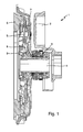
- FIG. 1 shows a first embodiment of the clutch assembly according to the invention 1.
- the clutch assembly 1 is covered with a clutch bell 2.
- the clutch assembly 1 has a slave cylinder 3, which extends rotationally symmetrical about a transmission shaft 4.
- the slave cylinder 3 presses on the tongues of a plate spring 5, which are connected to the coupling 6.
- the tongues of the disc spring 5 are passed through an opening 8 of the clutch cover 7, which bears with its end against a cover bearing 9 which is formed near the coupling 6.
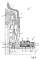
- the coupling assembly 1 is shown in a section.
- the slave cylinder 3 has a housing 10 which is mounted on a guide sleeve 11, wherein the guide sleeve 11 has a flange 12 which comprises the housing 10.
- a pressure chamber 13 Between the housing 10 and the guide sleeve 11 extends a pressure chamber 13, in which an axially movably mounted piston 14 is guided.
- the piston 14 is fixedly connected to a release bearing 15, which acts on a radially inner portion of the plate spring 5 in the axial direction with a force.
- the release bearing 15 is thereby pressed by a preload spring 16 axially against the tongues of the plate spring 5, wherein the preload spring 16 is mounted between the release bearing 15 and the housing 10 of the slave cylinder 3.
- the existing plastic housing 10 also has a radially mounted seal 22, which seals the housing 10 relative to the guide sleeve 11 radially on the pressure chamber 13. This ensures that the housing 10 is always pressed in the direction of the flange 12 of the guide sleeve 11 upon actuation of the coupling. At the same time a reliable sealing of the pressure chamber 13 is realized.
- the slave cylinder 3 has a reinforced guide sleeve 11, which is formed of a metal and has a thickness of about 3 mm.
- the guide sleeve 11th Compared to attacking forces much more stable than guide sleeves according to the prior art, the strength amounts to only 1 mm.
- the guide sleeve 11 is extended to the vicinity of the coupling 6 and has a groove 23 in which a snap ring 17 engages perpendicular to the guide sleeve 11. This snap ring 17 is mounted on the bearing shoulder of the inner ring 18 of the cover bearing 9.
- the cover bearing 9 is supported on the coupling 6 and is centered on the end stop 19 of the coupling 6 for the tongues of the plate spring 5 and placed.
- the cover bearing 9 may be formed in various embodiments.
- a helical or a deep groove ball bearing are just as conceivable as an axial needle roller bearing or an axial ball bearing.
- the snap ring 17 serves to establish the connection between the clutch 6 and the slave cylinder 3. This is done in a very simple manner in that it engages in the groove 23 of the guide sleeve 11.
- the cover bearing 9 only has to be placed, the slave cylinder 3 is inserted into the coupling 6 and used to complete the snap ring 17.
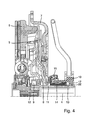
- FIG. 4 a second embodiment of the clutch assembly 1 is shown, which is from the FIG. 2 differs that the flange 12 of the guide sleeve 11 and the snap ring 17 are interchanged.
- the flange 12 protrudes near the clutch 6 approximately parallel to this in the interior of the clutch assembly 1, while the snap ring 17 fixes the housing 10.
- the seal 22 is arranged radially between the housing 10 and the guide sleeve 11 in front of the snap ring 17 in order to prevent separation of the housing 10 and the guide sleeve 11. All other components are related to FIG. 2 explained arrangement unchanged.
- the proposed clutch assembly 1 has a reduced radial size, since the cover bearing 9 and the clutch cover 7 require a smaller space. This not only leads to an increase in the variety of applications of the clutch assembly in motor vehicles with engines that are used as a longitudinal or transverse application, but also reduces the cost of manufacturing significantly.
Landscapes
- Chemical & Material Sciences (AREA)
- Organic Chemistry (AREA)
- Engineering & Computer Science (AREA)
- General Engineering & Computer Science (AREA)
- Mechanical Engineering (AREA)
- Mechanical Operated Clutches (AREA)
Abstract
Die Erfindung betrifft eine Kupplungsanordnung, insbesondere für eine Reibungskupplung, in einem Kupplungsausrücksystem eines Kraftfahrzeuges, umfassend einen Nehmerzylinder (3) mit einem Gehäuse (10) und einer Führungshülse (11), welche einen ringförmigen Druckraum (13) umschließen, in welchem ein Kolben (14) axial beweglich gelagert ist, der fest mit einem Ausrücklager verbunden ist, welcher eine Tellerfeder (5) mit einer Kraft in axialer Richtung beaufschlagt, wobei ein Deckellager fest mit einer Kupplungsabdeckung (7) verbunden ist.The invention relates to a clutch arrangement, in particular for a friction clutch, in a clutch release system of a motor vehicle, comprising a slave cylinder (3) with a housing (10) and a guide sleeve (11) which surround an annular pressure chamber (13) in which a piston ( 14) is mounted axially movable, which is fixedly connected to a release bearing, which acts on a plate spring (5) with a force in the axial direction, wherein a cover bearing is fixedly connected to a coupling cover (7).
Bei einer Kupplungsanordnung, welche einen reduzierten Bauraum benötigt, ist das Deckellager (9) axial beabstandet zu dem Nehmerzylinder (3) in Richtung Kupplung gelagert, wobei die Kupplungsabdeckung (7) zwischen dem Deckellager und dem Ausrücklager (15) angeordnet ist und insbesondere die Tellerfeder zwischen dem Deckellager und dem Ausrücklager verläuft.

Description
Die Erfindung betrifft eine Kupplungsanordnung, insbesondere für eine Reibungskupplung in einem Kupplungsausrücksystem eines Kraftfahrzeuges, umfassend einen Nehmerzylinder mit einem Gehäuse und einer Führungshülse, welche einen ringförmigen Druckraum umschließen, in welchem ein Kolben axial beweglich gelagert ist, der fest mit einem Ausrücklager verbunden ist, welches eine Tellerfeder in axialer Richtung mit einer Kraft beaufschlagt, wobei ein Deckellager fest mit einer Kupplungsabdeckung verbunden ist.The invention relates to a clutch assembly, in particular for a friction clutch in a clutch release system of a motor vehicle, comprising a slave cylinder with a housing and a guide sleeve, which enclose an annular pressure chamber in which a piston is mounted axially movable, which is fixedly connected to a release bearing, which a plate spring in the axial direction acted upon by a force, wherein a cover bearing is fixedly connected to a clutch cover.
In Kraftfahrzeugen werden Kupplungssysteme eingesetzt, um den Kraftschluss zwischen einem Motor und einem Getriebe zu trennen bzw. herzustellen. Dabei wird ein Ausrücksystem, beispielsweise ein als Hydraulikzylinder ausgebildeter Nehmerzylinder, in einer hydraulischen Kupplungsbetätigungseinrichtung in Richtung eines Ausrückelementes, beispielsweise einer Kupplungsscheibe bewegt, wodurch die Kupplung geschlossen wird. Ausrücksysteme übertragen dabei Kräfte, die infolge eines gedrückten Kupplungspedals oder eines Signals einer Steuerelektronik zur Unterbrechung des Momentenflusses zwischen dem im Kraftfahrzeug verbauten Motor und dem Getriebe führen.In motor vehicles clutch systems are used to separate or establish the adhesion between an engine and a transmission. In this case, a release system, for example a slave cylinder designed as a hydraulic cylinder, is moved in a hydraulic clutch actuation device in the direction of a disengagement element, for example a clutch disc, whereby the clutch is closed. Release systems transmit forces that lead due to a depressed clutch pedal or a signal control electronics to interrupt the flow of torque between the built-in motor vehicle engine and the transmission.
Aus der
Der Erfindung liegt somit die Aufgabe zugrunde, eine Kupplungsanordnung anzugeben, welche nur einen sehr geringen radialen Bauraum benötigt und für Längs- als auch Queranwendungen des Motors verwendet werden kann.The invention is therefore based on the object to provide a clutch assembly which requires only a very small radial space and can be used for longitudinal and transverse applications of the engine.
Erfindungsgemäß wird die Aufgabe dadurch gelöst, dass das Deckellager axial beabstandet zu dem Nehmerzylinder in Richtung Kupplung gelagert ist, wobei die Kupplungsabdeckung zwischen dem Deckellager und dem Ausrücklager geführt ist und insbesondere die Tellerfeder zwischen dem Deckellager und dem Ausrücklager verläuft. Durch diese Ausgestaltung entfällt die Verwendung eines zusätzlichen Blechflansches, was den Vorteil hat, dass der radiale Bauraum für die Kupplungsanordnung wesentlich reduziert wird.According to the invention the object is achieved in that the cover bearing is axially spaced from the slave cylinder mounted in the direction of coupling, wherein the clutch cover is guided between the cover bearing and the release bearing and in particular the plate spring between the cover bearing and the release bearing. This embodiment eliminates the use of an additional sheet metal flange, which has the advantage that the radial space for the clutch assembly is substantially reduced.
Vorteilhafterweise ist die, das Deckellager abdeckende Kupplungsabdeckung nahe einer Getriebewelle, welche von dem Nehmerzylinder umfasst ist, nach innen in Richtung der Kupplung geführt. Bei einer solchen Ausgestaltung kann auch das Deckellager wesentlich kleiner gestaltet werden. Die Kosten für ein neues Deckellager werden reduziert und sind mit den Kosten eines Ausrücklagers vergleichbar.Advantageously, the clutch cover covering the cover bearing is guided inwardly towards the clutch near a gear shaft comprised by the slave cylinder. In such an embodiment, the cover bearing can be made much smaller. The cost of a new cover bearing is reduced and is comparable to the cost of a release bearing.
In einer Ausgestaltung ist das mit den Zungen der Tellerfeder in Berührung stehende Ausrücklager axial zwischen dem Deckellager und dem Nehmerzylinder angeordnet. Dabei wird nur das Deckellager durch die Kupplungsabdeckung abgedeckt, wodurch der Bauraum für die Kupplungsabdeckung reduziert wird. Durch diese Ausgestaltung ist insbesondere genügend Bauraum vorhanden, um eine solche Kupplungsanordnung bei Queranwendungen von Motoren in Kraftfahrzeugen einzusetzen.In one embodiment, the releasing bearing in contact with the tongues of the plate spring is arranged axially between the cover bearing and the slave cylinder. Only the cover bearing is covered by the clutch cover, whereby the space for the clutch cover is reduced. By this configuration, in particular, sufficient space is available to use such a clutch assembly in transverse applications of engines in motor vehicles.
In einer Variante ist das Deckellager an einem Endanschlag der Kupplung für die Zungen der Tellerfeder zentriert. Somit werden an sich in der Kupplung vorhandene Bauelemente zur Zentrierung des Deckellagers benutzt und es entfallen zusätzliche Bauteile zur Zentrierung des Deckellagers. Durch den Wegfall von zusätzlichen Bauteilen zur Zentrierung des Deckellagers reduzieren sich die Herstellungskosten der Kupplungsanordnung. Darüber hinaus besteht ein geschlossener Kraftschluss zwischen der Führungshülse und dem Endanschlag der Zungen der Tellerfeder.In one variant, the cover bearing is centered on an end stop of the coupling for the tongues of the diaphragm spring. Thus, components which are present in the coupling are used for centering the cover bearing and additional components for centering the cover bearing are dispensed with. The elimination of additional components for centering the cover bearing reduces the manufacturing cost of the clutch assembly. In addition, there is a closed frictional connection between the guide sleeve and the end stop of the tongues of the plate spring.
Das Deckellager kann in vielfältiger Form realisiert werden. So kann das Deckellager als Schrägkugellager oder als Rillenkugellager oder als Axial-Nadellager oder als Axial-Kugellager ausgebildet sein. Die vorgeschlagene Kupplungsanordnung ist somit bei einer großen Vielfalt von Deckellagern einsetzbar.The cover bearing can be realized in many forms. Thus, the cover bearing can be designed as angular contact ball bearings or as deep groove ball bearings or as axial needle roller bearings or as axial ball bearings. The proposed clutch assembly is thus applicable to a wide variety of cover bearings.
In einer Variante ist das Deckellager auf der verstärkten Führungshülse angeordnet, welche insbesondere mit einem Flansch das Gehäuse des Nehmerzylinders umgreift. Die um mehrere Millimeter verstärkte Führungshülse dient somit gleichzeitig als Träger für das Deckellager nahe der Kupplung.In a variant, the cover bearing is arranged on the reinforced guide sleeve, which engages around the housing of the slave cylinder, in particular with a flange. The order of several Millimeter reinforced guide sleeve thus serves as a support for the cover bearing near the clutch.
In einer Weiterbildung weist das Gehäuse eine radial angeordnete Dichtung auf, welche das Gehäuse gegen die Führungshülse abdichtet. Durch diese radiale Dichtung wird gewährleistet, dass bei jeder Betätigung der Kupplung das aus Kunststoff bestehende Gehäuse immer in Richtung des Flansches der Führungshülse gedrückt wird. Neben einer sicheren Abdichtung des Druckraumes wird die Verbindung zwischen Führungshülse und Gehäuse bei einer Druckbeaufschlagung stabilisiert.In a development, the housing has a radially arranged seal, which seals the housing against the guide sleeve. This radial seal ensures that each time the coupling is actuated, the housing made of plastic is always pressed in the direction of the flange of the guide sleeve. In addition to a secure seal of the pressure chamber, the connection between the guide sleeve and housing is stabilized at a pressurization.
Vorteilhafterweise weist die Führungshülse eine Nut auf, in welcher ein Sprengring eingreift. Der Sprengring dient dabei zur Herstellung der mechanischen Verbindung zwischen der Kupplung und dem Nehmerzylinder. Diese mechanische Verbindung ist sehr einfach herstellbar und stabil gegenüber einer Kraftbeaufschlagung.Advantageously, the guide sleeve has a groove in which a snap ring engages. The snap ring serves to produce the mechanical connection between the clutch and the slave cylinder. This mechanical connection is very easy to produce and stable against a force.
In einer Ausgestaltung ist die Nut auf der dem Flansch abgewandten Seite der Führungshülse ausgebildet, wobei insbesondere der Sprengring an einer Lagerschulter eines Innenringes des Deckellagers angreift. Somit wird eine Stabilisierung des Sprengringes mit an sich in der Kupplungsanordnung vorhandenen Bauteilen realisiert, was die Kosten bei der Herstellung der Kupplungsanordnung reduziert. Die bei einer Kupplungsbetätigung auftretenden Ausrückkräfte werden dabei sowohl von der Führungshülse, insbesondere deren Flansch, als auch dem Sprengring aufgenommen.In one embodiment, the groove is formed on the side facing away from the flange of the guide sleeve, wherein in particular the snap ring engages a bearing shoulder of an inner ring of the cover bearing. Thus, a stabilization of the snap ring is realized with existing in the clutch assembly components, which reduces the cost of manufacturing the clutch assembly. The disengagement forces occurring during a clutch actuation are absorbed both by the guide sleeve, in particular its flange, as well as the snap ring.
In einer Variante übt eine Vorlastfeder eine Kraft auf das Deckellager aus, wobei die Vorlastfeder vorzugsweise zwischen Gehäuse und Ausrücklager angeordnet ist. Mittels der Vorlastfeder wird gewährleistet, dass die Laufbahnen im Deckellager in einem ständigen Kontakt zu den Wälzkörpern des Deckellagers stehen.In one variant, a preload spring exerts a force on the cover bearing, wherein the preload spring is preferably arranged between the housing and the release bearing. By means of the preload spring ensures that the raceways are in the cover bearing in constant contact with the rolling elements of the cover bearing.
Die Erfindung lässt zahlreiche Ausführungsformen zu. Eine davon soll anhand der in der Zeichnung dargestellten Figuren näher erläutert werden.The invention allows numerous embodiments. One of them will be explained in more detail with reference to the figures shown in the drawing.
Es zeigt:
- Figur 1:
- eine erste Ausführungsform der erfindungsgemäßen Kupplungsanordnung
- Figur 2:
- einen Ausschnitt aus der Kupplungsanordnung gemäß
Figur 1 - Figur 3:
- eine Draufsicht auf die Kupplungsanordnung nach
Figur 1 aus Richtung der Kupplung - Figur 4:
- eine zweite Ausführungsform der erfindungsgemäßen Kupplungsanordnung
- FIG. 1:
- A first embodiment of the coupling arrangement according to the invention
- FIG. 2:
- a section of the clutch assembly according to
FIG. 1 - FIG. 3:
- a plan view of the clutch assembly according to
FIG. 1 from the direction of the clutch - FIG. 4:
- a second embodiment of the coupling arrangement according to the invention
Gleiche Merkmale sind mit gleichen Bezugszeichen gekennzeichnet.Identical features are identified by the same reference numerals.
In
Das aus Kunststoff bestehende Gehäuse 10 weist darüber hinaus eine radial angebrachte Dichtung 22 auf, welche das Gehäuse 10 gegenüber der Führungshülse 11 radial am Druckraum 13 abdichtet. Hierdurch wird gewährleistet, dass das Gehäuse 10 bei Betätigung der Kupplung immer in Richtung des Flansches 12 der Führungshülse 11 gedrückt wird. Gleichzeitig wird eine zuverlässige Abdichtung des Druckraumes 13 realisiert.The existing
Der Nehmerzylinder 3 verfügt dabei über eine verstärkte Führungshülse 11, welche aus einem Metall gebildet ist und eine Stärke von ca. 3 mm aufweist. Dadurch ist die Führungshülse 11 gegenüber angreifenden Kräften wesentlich stabiler als Führungshülsen nach dem Stand der Technik, deren Stärke sich lediglich auf 1 mm beläuft. Die Führungshülse 11 ist bis in die Nähe der Kupplung 6 verlängert und weist eine Nut 23 auf, in welcher ein Sprengring 17 senkrecht zur Führungshülse 11 eingreift. Dieser Sprengring 17 ist an der Lagerschulter des Innenringes 18 des Deckellagers 9 gelagert. Das Deckellager 9 ist an der Kupplung 6 abgestützt und wird am Endanschlag 19 der Kupplung 6 für die Zungen der Tellerfeder 5 zentriert und aufgesetzt.The
Insbesondere aus
Das Deckellager 9 kann in verschiedenen Ausführungsformen ausgebildet sein. So sind ein Schräg- oder ein Rillenkugellager genauso denkbar wie ein Axial-Nadellager oder ein Axial-Kugellager. Der Sprengring 17 dient dazu, die Verbindung zwischen der Kupplung 6 und dem Nehmerzylinder 3 herzustellen. Dies erfolgt in sehr einfacher Art und Weise dadurch, dass dieser in die Nut 23 der Führungshülse 11 eingreift.The
Im Montageprozess bedeutet dies, dass die Kupplung 6 und der Nehmerzylinder 3 getrennt montiert werden können. Bei dem Verbauen der Kupplung 6 mit dem Nehmerzylinder 3 muss das Deckellager 9 nur aufgesetzt, der Nehmerzylinder 3 in die Kupplung 6 eingeführt und zum Abschluss der Sprengring 17 eingesetzt werden.In the assembly process, this means that the
In
Die vorgeschlagene Kupplungsanordnung 1 weist eine reduzierte radiale Baugröße auf, da das Deckellager 9 und die Kupplungsabdeckung 7 einen kleineren Bauraum benötigen. Dies führt nicht nur zur einer Erhöhung der Vielfalt der Einsatzmöglichkeiten der Kupplungsanordnung in Kraftfahrzeugen mit Motoren, die als Längs- oder Queranwendung genutzt werden, sondern reduziert auch die Herstellungskosten wesentlich.The proposed clutch assembly 1 has a reduced radial size, since the
- 11
- Kupplungsanordnungclutch assembly
- 22
- KupplungsglockeKupplungsglocke
- 33
- Nehmerzylinderslave cylinder
- 44
- Getriebewellegear shaft
- 55
- TellerfederBelleville spring
- 66
- Kupplungclutch
- 77
- Kupplungsabdeckungclutch cover
- 88th
- Öffnungopening
- 99
- Deckellagercover support
- 1010
- Gehäusecasing
- 1111
- Führungshülseguide sleeve
- 1212
- Flanschflange
- 1313
- Druckraumpressure chamber
- 1414
- Kolbenpiston
- 1515
- Ausrücklagerrelease bearing
- 1616
- Vorlastfederpreload
- 1717
- Sprengringsnap ring
- 1818
- Innenring des DeckellagersInner ring of the cover bearing
- 1919
- Endanschlagend stop
- 2020
- Stegweb
- 2121
- Ringring
- 2222
- Dichtungpoetry
- 2323
- Nutgroove
Claims (10)
Priority Applications (1)
| Application Number | Priority Date | Filing Date | Title |
|---|---|---|---|
| EP20130002813 EP2835548A1 (en) | 2013-08-08 | 2013-08-08 | Coupling assembly, particularly for a friction clutch in a clutch disengaging system of a motor vehicle |
Applications Claiming Priority (1)
| Application Number | Priority Date | Filing Date | Title |
|---|---|---|---|
| EP20130002813 EP2835548A1 (en) | 2013-08-08 | 2013-08-08 | Coupling assembly, particularly for a friction clutch in a clutch disengaging system of a motor vehicle |
Publications (1)
| Publication Number | Publication Date |
|---|---|
| EP2835548A1 true EP2835548A1 (en) | 2015-02-11 |
Family
ID=52183102
Family Applications (1)
| Application Number | Title | Priority Date | Filing Date |
|---|---|---|---|
| EP20130002813 Withdrawn EP2835548A1 (en) | 2013-08-08 | 2013-08-08 | Coupling assembly, particularly for a friction clutch in a clutch disengaging system of a motor vehicle |
Country Status (1)
| Country | Link |
|---|---|
| EP (1) | EP2835548A1 (en) |
Cited By (2)
| Publication number | Priority date | Publication date | Assignee | Title |
|---|---|---|---|---|
| CN109996971A (en) * | 2016-10-13 | 2019-07-09 | Zf腓特烈斯哈芬股份公司 | Control housing for a clutch actuator |
| WO2019238157A1 (en) * | 2018-06-12 | 2019-12-19 | Schaeffler Technologies AG & Co. KG | Motor vehicle clutch slave cylinder having a steel flange and a pressure-chamber delimiting part comprising plastic, and motor vehicle clutch |
Citations (4)
| Publication number | Priority date | Publication date | Assignee | Title |
|---|---|---|---|---|
| DE19724836A1 (en) * | 1997-06-12 | 1998-12-17 | Schaeffler Waelzlager Ohg | Hydraulic clutch for vehicles |
| DE102008004150A1 (en) * | 2007-01-31 | 2008-08-07 | Luk Lamellen Und Kupplungsbau Beteiligungs Kg | Torque transfer device |
| DE102008021161A1 (en) | 2007-05-18 | 2008-11-20 | Luk Lamellen Und Kupplungsbau Beteiligungs Kg | friction clutch |
| DE102012203597A1 (en) * | 2011-03-30 | 2012-10-04 | Borgwarner Inc. | Arrangement, particularly wet dual clutch transmission arrangement, for use in vehicle, has outer input shaft arranged concentrically to inner input shaft, and clutch is comprised of radially aligned inner and outer clutch housing |
-
2013
- 2013-08-08 EP EP20130002813 patent/EP2835548A1/en not_active Withdrawn
Patent Citations (4)
| Publication number | Priority date | Publication date | Assignee | Title |
|---|---|---|---|---|
| DE19724836A1 (en) * | 1997-06-12 | 1998-12-17 | Schaeffler Waelzlager Ohg | Hydraulic clutch for vehicles |
| DE102008004150A1 (en) * | 2007-01-31 | 2008-08-07 | Luk Lamellen Und Kupplungsbau Beteiligungs Kg | Torque transfer device |
| DE102008021161A1 (en) | 2007-05-18 | 2008-11-20 | Luk Lamellen Und Kupplungsbau Beteiligungs Kg | friction clutch |
| DE102012203597A1 (en) * | 2011-03-30 | 2012-10-04 | Borgwarner Inc. | Arrangement, particularly wet dual clutch transmission arrangement, for use in vehicle, has outer input shaft arranged concentrically to inner input shaft, and clutch is comprised of radially aligned inner and outer clutch housing |
Cited By (3)
| Publication number | Priority date | Publication date | Assignee | Title |
|---|---|---|---|---|
| CN109996971A (en) * | 2016-10-13 | 2019-07-09 | Zf腓特烈斯哈芬股份公司 | Control housing for a clutch actuator |
| WO2019238157A1 (en) * | 2018-06-12 | 2019-12-19 | Schaeffler Technologies AG & Co. KG | Motor vehicle clutch slave cylinder having a steel flange and a pressure-chamber delimiting part comprising plastic, and motor vehicle clutch |
| CN112262269A (en) * | 2018-06-12 | 2021-01-22 | 舍弗勒技术股份两合公司 | Clutch driven cylinder for motor vehicle comprising steel flange and plastic surrounding pressure cavity limiting part, and motor vehicle clutch |
Similar Documents
| Publication | Publication Date | Title |
|---|---|---|
| DE102010060889B4 (en) | Synchronizing device for a transmission | |
| EP3078873B1 (en) | Connexion assembly with a lead adaptor for connecting a fluid tube to a master cylinder or slave cylinder housing | |
| WO2017063649A1 (en) | Slave cylinder for a hydraulic release system for actuating a friction clutch | |
| EP1365167B1 (en) | Actuating device for a friction clutch for a motor vehicle | |
| DE102013209995A1 (en) | Coupling arrangement, in particular for a friction clutch in a clutch release system of a motor vehicle | |
| DE102010043595A1 (en) | Bearing for transmission shaft, particularly for output shaft of motor vehicle transmission, particularly motor vehicle automatic transmission, has rolling bearing, which is incorporated in bearing bore of transmission housing | |
| EP2924311B1 (en) | Central clutch release for a hydraulic or pneumatic clutch actuating device, in particular for a motor vehicle | |
| EP2835548A1 (en) | Coupling assembly, particularly for a friction clutch in a clutch disengaging system of a motor vehicle | |
| DE102013218116A1 (en) | Piston-cylinder-arrangement, particularly slave cylinder, for hydraulic clutch actuating device, has cylinder housing made from plastic, in which piston is mounted for actuating clutch release bearing in axially movable manner | |
| DE102011100903A1 (en) | Hydraulic clutch or brake actuation system, has master cylinder, slave cylinder connected to pressure line, where information transmitter is radially movable, and is mounted on piston in radially outwardly biased manner | |
| EP3177844B1 (en) | Master cylinder with guide sleeve for a sealing lip of the sniffer system | |
| DE102011106460A1 (en) | Slave cylinder i.e. concentric slave cylinder, for hydraulic disengaging system of friction clutch of motor vehicle, has spring arranged between annular piston and inner wall of housing, where wall is arranged above pressure chamber | |
| DE102015211831A1 (en) | Release system for a clutch actuation system, in particular with a pneumatic transmission path | |
| WO2015192843A1 (en) | Master cylinder for a clutch disengagement system | |
| DE102015201643A1 (en) | Hydraulic cylinder for a clutch actuation system or brake actuation system with a displacement encoder | |
| DE102009014474A1 (en) | Slave cylinder i.e. concentric slave cylinder, for hydraulic disengaging system of friction clutch of motor vehicle, has annular piston provided with seal at pressure chamber side, where annular piston consists of transformed plate | |
| EP2772625B1 (en) | Drive assembly for a unit of an internal combustion engine | |
| WO2015058760A2 (en) | Piston/cylinder assembly, in particular for a clutch-actuating device of a motor vehicle | |
| DE102014212193A1 (en) | clutch release | |
| DE102012107382A1 (en) | Radial shaft sealing ring for shaft, has centrifugal force compensator formed from sealing lip portion, supporting portion and counterweight portion, where supporting portion of is rested on end portion radial supporting ring section | |
| EP1884677B1 (en) | Clutch device, in particular motor vehicle clutch device | |
| DE102011087101A1 (en) | Release system for hydraulic operation of dual clutch of vehicle, has annular piston arranged coaxial to clutch release bearing and partially penetrating inner ring of bearing, where connector connects piston with inner ring | |
| DE102011016004B4 (en) | Central engagement device with two partial engagement systems for actuating a friction clutch of vehicles | |
| WO2010048915A1 (en) | Clutch actuating unit having hydraulic release apparatus | |
| DE102012221225A1 (en) | Piston unit for e.g. hydraulic release mechanism for operating clutch in passenger car, has piston forming stop with housing and another stop with guide sleeve, so that piston is moved between positions that are spaced from each other |
Legal Events
| Date | Code | Title | Description |
|---|---|---|---|
| PUAB | Information related to the publication of an a document modified or deleted |
Free format text: ORIGINAL CODE: 0009199EPPU |
|
| PUAI | Public reference made under article 153(3) epc to a published international application that has entered the european phase |
Free format text: ORIGINAL CODE: 0009012 |
|
| PUAI | Public reference made under article 153(3) epc to a published international application that has entered the european phase |
Free format text: ORIGINAL CODE: 0009012 |
|
| 17P | Request for examination filed |
Effective date: 20130531 |
|
| AK | Designated contracting states |
Kind code of ref document: A1 Designated state(s): AL AT BE BG CH CY CZ DE DK EE ES FI FR GB GR HR HU IE IS IT LI LT LU LV MC MK MT NL NO PL PT RO RS SE SI SK SM TR |
|
| AX | Request for extension of the european patent |
Extension state: BA ME |
|
| RAP1 | Party data changed (applicant data changed or rights of an application transferred) |
Owner name: SCHAEFFLER TECHNOLOGIES AG & CO. KG |
|
| R17P | Request for examination filed (corrected) |
Effective date: 20150811 |
|
| RBV | Designated contracting states (corrected) |
Designated state(s): AL AT BE BG CH CY CZ DE DK EE ES FI FR GB GR HR HU IE IS IT LI LT LU LV MC MK MT NL NO PL PT RO RS SE SI SK SM TR |
|
| 17Q | First examination report despatched |
Effective date: 20170803 |
|
| STAA | Information on the status of an ep patent application or granted ep patent |
Free format text: STATUS: THE APPLICATION IS DEEMED TO BE WITHDRAWN |
|
| 18D | Application deemed to be withdrawn |
Effective date: 20171214 |
|
| P01 | Opt-out of the competence of the unified patent court (upc) registered |
Effective date: 20230523 |