EP2835546B1 - Unité de palier à roulement avec réservoir de graisse - Google Patents
Unité de palier à roulement avec réservoir de graisse Download PDFInfo
- Publication number
- EP2835546B1 EP2835546B1 EP14180225.6A EP14180225A EP2835546B1 EP 2835546 B1 EP2835546 B1 EP 2835546B1 EP 14180225 A EP14180225 A EP 14180225A EP 2835546 B1 EP2835546 B1 EP 2835546B1
- Authority
- EP
- European Patent Office
- Prior art keywords
- grease
- rolling bearing
- outer ring
- spacer
- channels
- Prior art date
- Legal status (The legal status is an assumption and is not a legal conclusion. Google has not performed a legal analysis and makes no representation as to the accuracy of the status listed.)
- Not-in-force
Links
Images


Classifications
-
- F—MECHANICAL ENGINEERING; LIGHTING; HEATING; WEAPONS; BLASTING
- F16—ENGINEERING ELEMENTS AND UNITS; GENERAL MEASURES FOR PRODUCING AND MAINTAINING EFFECTIVE FUNCTIONING OF MACHINES OR INSTALLATIONS; THERMAL INSULATION IN GENERAL
- F16C—SHAFTS; FLEXIBLE SHAFTS; ELEMENTS OR CRANKSHAFT MECHANISMS; ROTARY BODIES OTHER THAN GEARING ELEMENTS; BEARINGS
- F16C33/00—Parts of bearings; Special methods for making bearings or parts thereof
- F16C33/30—Parts of ball or roller bearings
- F16C33/66—Special parts or details in view of lubrication
- F16C33/6603—Special parts or details in view of lubrication with grease as lubricant
- F16C33/6607—Retaining the grease in or near the bearing
- F16C33/6618—Retaining the grease in or near the bearing in a reservoir in the sealing means
-
- F—MECHANICAL ENGINEERING; LIGHTING; HEATING; WEAPONS; BLASTING
- F16—ENGINEERING ELEMENTS AND UNITS; GENERAL MEASURES FOR PRODUCING AND MAINTAINING EFFECTIVE FUNCTIONING OF MACHINES OR INSTALLATIONS; THERMAL INSULATION IN GENERAL
- F16C—SHAFTS; FLEXIBLE SHAFTS; ELEMENTS OR CRANKSHAFT MECHANISMS; ROTARY BODIES OTHER THAN GEARING ELEMENTS; BEARINGS
- F16C33/00—Parts of bearings; Special methods for making bearings or parts thereof
- F16C33/30—Parts of ball or roller bearings
- F16C33/66—Special parts or details in view of lubrication
- F16C33/6603—Special parts or details in view of lubrication with grease as lubricant
- F16C33/6607—Retaining the grease in or near the bearing
-
- F—MECHANICAL ENGINEERING; LIGHTING; HEATING; WEAPONS; BLASTING
- F16—ENGINEERING ELEMENTS AND UNITS; GENERAL MEASURES FOR PRODUCING AND MAINTAINING EFFECTIVE FUNCTIONING OF MACHINES OR INSTALLATIONS; THERMAL INSULATION IN GENERAL
- F16C—SHAFTS; FLEXIBLE SHAFTS; ELEMENTS OR CRANKSHAFT MECHANISMS; ROTARY BODIES OTHER THAN GEARING ELEMENTS; BEARINGS
- F16C19/00—Bearings with rolling contact, for exclusively rotary movement
- F16C19/02—Bearings with rolling contact, for exclusively rotary movement with bearing balls essentially of the same size in one or more circular rows
- F16C19/14—Bearings with rolling contact, for exclusively rotary movement with bearing balls essentially of the same size in one or more circular rows for both radial and axial load
- F16C19/16—Bearings with rolling contact, for exclusively rotary movement with bearing balls essentially of the same size in one or more circular rows for both radial and axial load with a single row of balls
- F16C19/163—Bearings with rolling contact, for exclusively rotary movement with bearing balls essentially of the same size in one or more circular rows for both radial and axial load with a single row of balls with angular contact
-
- F—MECHANICAL ENGINEERING; LIGHTING; HEATING; WEAPONS; BLASTING
- F16—ENGINEERING ELEMENTS AND UNITS; GENERAL MEASURES FOR PRODUCING AND MAINTAINING EFFECTIVE FUNCTIONING OF MACHINES OR INSTALLATIONS; THERMAL INSULATION IN GENERAL
- F16C—SHAFTS; FLEXIBLE SHAFTS; ELEMENTS OR CRANKSHAFT MECHANISMS; ROTARY BODIES OTHER THAN GEARING ELEMENTS; BEARINGS
- F16C2322/00—Apparatus used in shaping articles
- F16C2322/39—General build up of machine tools, e.g. spindles, slides, actuators
-
- F—MECHANICAL ENGINEERING; LIGHTING; HEATING; WEAPONS; BLASTING
- F16—ENGINEERING ELEMENTS AND UNITS; GENERAL MEASURES FOR PRODUCING AND MAINTAINING EFFECTIVE FUNCTIONING OF MACHINES OR INSTALLATIONS; THERMAL INSULATION IN GENERAL
- F16C—SHAFTS; FLEXIBLE SHAFTS; ELEMENTS OR CRANKSHAFT MECHANISMS; ROTARY BODIES OTHER THAN GEARING ELEMENTS; BEARINGS
- F16C33/00—Parts of bearings; Special methods for making bearings or parts thereof
- F16C33/30—Parts of ball or roller bearings
- F16C33/66—Special parts or details in view of lubrication
- F16C33/6603—Special parts or details in view of lubrication with grease as lubricant
- F16C33/6607—Retaining the grease in or near the bearing
- F16C33/6614—Retaining the grease in or near the bearing in recesses or cavities provided in retainers, races or rolling elements
-
- F—MECHANICAL ENGINEERING; LIGHTING; HEATING; WEAPONS; BLASTING
- F16—ENGINEERING ELEMENTS AND UNITS; GENERAL MEASURES FOR PRODUCING AND MAINTAINING EFFECTIVE FUNCTIONING OF MACHINES OR INSTALLATIONS; THERMAL INSULATION IN GENERAL
- F16C—SHAFTS; FLEXIBLE SHAFTS; ELEMENTS OR CRANKSHAFT MECHANISMS; ROTARY BODIES OTHER THAN GEARING ELEMENTS; BEARINGS
- F16C33/00—Parts of bearings; Special methods for making bearings or parts thereof
- F16C33/30—Parts of ball or roller bearings
- F16C33/66—Special parts or details in view of lubrication
- F16C33/6603—Special parts or details in view of lubrication with grease as lubricant
- F16C33/6622—Details of supply and/or removal of the grease, e.g. purging grease
-
- F—MECHANICAL ENGINEERING; LIGHTING; HEATING; WEAPONS; BLASTING
- F16—ENGINEERING ELEMENTS AND UNITS; GENERAL MEASURES FOR PRODUCING AND MAINTAINING EFFECTIVE FUNCTIONING OF MACHINES OR INSTALLATIONS; THERMAL INSULATION IN GENERAL
- F16C—SHAFTS; FLEXIBLE SHAFTS; ELEMENTS OR CRANKSHAFT MECHANISMS; ROTARY BODIES OTHER THAN GEARING ELEMENTS; BEARINGS
- F16C33/00—Parts of bearings; Special methods for making bearings or parts thereof
- F16C33/30—Parts of ball or roller bearings
- F16C33/66—Special parts or details in view of lubrication
- F16C33/6603—Special parts or details in view of lubrication with grease as lubricant
- F16C33/6629—Details of distribution or circulation inside the bearing, e.g. grooves on the cage or passages in the rolling elements
Definitions
- WO 2010/010897 describes a rolling bearing unit including an inner ring, an outer ring, a plurality of balls, a cage, a seal and an annular grease reserving member.
- the balls are rolling elements interposed between the inner ring and the outer ring.
- the cage retains the balls located at prescribed intervals in the circumferential direction.
- One axial end of an annular space defined between the inner ring and the outer ring is sealed by the seal.
- the grease reserving member is disposed near an annular groove located adjacent to a guide surface of the outer ring, which guides rotation of the cage. The lubricant is reserved in the grease reserving member.
- JP 2005-180629 A describes a rolling bearing including an inner ring, an outer ring, a plurality of rolling elements, a grease reservoir forming member and a clearance forming piece.
- the rolling elements are interposed between raceway surfaces of the inner and outer rings.
- the grease reservoir forming member is disposed in contact with the outer ring.
- the clearance forming piece extends from the grease reservoir to a position near the raceway surface of the outer ring to define a clearance along an inner peripheral face of the outer ring.
- cracks may be formed in the grease in the grease reservoir as base oil that is contained in the grease is supplied. If such cracks are successively connected to each other over the entire circumference of the bearing, at a position near a communication passage between the grease reservoir and the bearing, the base oil in the grease near the bearing is depleted although the grease remains in the grease reservoir, As a result, a supply of the base oil is interrupted. In the bearing unit in which a supply of the base oil is interrupted, the bearing lubrication performance is lost after the base oil in the bearing is completely consumed. After the bearing lubrication performance is lost, it is difficult to keep using the bearing unit for a long time.
- JP 2005-180629 A describes a configuration in which a small clearance is defined between the outer ring and the clearance forming piece.
- the base oil that is contained in the grease is supplied to a position near the raceway surface of the outer ring, in order to prolong the service life of the bearing having a satisfactory lubrication performance.
- the shape of the clearance forming piece needs to be accurately designed to form a small clearance. This complicates the configuration of the rolling bearing unit.
- One object of the invention is to provide a rolling bearing unit that is simply configured and that makes it possible to keep supplying base oil contained in grease to a bearing for a long time, thereby prolonging its service life.
- a rolling bearing unit and a method according to the invention are provided according to claims 1 and 5, respectively.
- FIG. 1 is a sectional view of a rolling bearing unit 1 according to an embodiment of the invention.
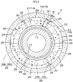
- FIG. 2 is a sectional view of a grease reserving member 4 in FIG. 1 , illustrating a section obtained by cutting the rolling bearing unit 1 along the line II-II in FIG. 1 .
- the rolling bearing unit 1 is a device that supports, example, a main spindle 2 (on which a rolling bearing is supported) of a machine tool.
- the rolling bearing unit 1 includes a rolling bearing 3 and the grease reserving member 4.
- the rolling bearing 3 is an angular contact ball bearing.
- the grease reserving member 4 is an example of a spacer according to the invention, which is disposed adjacent to the rolling bearing 3.
- the rolling bearing 3 includes an inner ring 5, an outer ring 6, rolling elements 7, a cylindrical cage 8 and a seal 9.
- the inner ring 5 is fitted onto the main spindle 2.
- the outer ring 6 is fitted to an inner periphery of a housing (not illustrated) of the machine tool.
- the rolling elements 7 are interposed between the inner ring 5 and the outer ring 6.
- the cage 8 retains the rolling elements 7 located at prescribed intervals in a circumferential direction Y.
- the seal 9 seals an annular space defined between the inner ring 5 and the outer ring 6, at one end (right end in FIG. 1 ; the end on the opposite side of the annular space from the grease reserving member 4) in an axial direction X (axial direction of the main spindle 2).
- the angular contact ball bearing is adopted as the rolling bearing 3.
- a deep groove ball bearing, a cylindrical roller bearing, a tapered roller bearing or the like may be adopted as the rolling bearing 3.
- An inner ring raceway surface 10, on which the rolling elements 7 roll, is formed in a center portion of an outer peripheral face of the inner ring 5 in the axial direction X.
- First seal grooves 11 are formed in opposite end portions of the outer peripheral face of the inner ring 5 in the axial direction X.
- An inner peripheral portion (seal lip) of the seal 9 is fitted in one of the first seal grooves 11, which is located more distant from the grease reserving member 4 than the other first seal groove 11 is in the axial direction X (the first seal groove 11 located on the right side in FIG. 1 ).
- An outer ring raceway surface 12, on which the rolling elements 7 roll, is formed in a center portion of an inner peripheral face of the outer ring 6 in the axial direction X.
- Second seal grooves 13 are formed in opposite end portions of the inner peripheral face of the outer ring 6 in the axial direction X.
- An outer peripheral portion (seal lip) of the seal 9 is fitted in one of the second seal grooves 13, which is located more distant from the grease reserving member 4 than the other second seal groove 13 is in the axial direction X (the second seal groove 13 located on the right side in FIG. 1 ).
- the second seal groove 13 located closer to the grease reserving member 4 in the axial direction X serves an annular groove 14 in which grease G is reserved.
- the annular groove 14 is defined by an annular recess formed in an end portion of the outer ring 6, which is located close to the grease reserving member 4.
- the annular groove 14 is filled with the grease G for initial lubrication in advance.
- the grease reserving member 4 includes an inner ring spacer 15, an outer ring spacer 16, and an oil reserving ring 18.
- the inner ring spacer 15 is fitted onto the main spindle 2.
- the outer ring spacer 16 is formed so as to surround the inner ring spacer 15 to define an annular space 17 between the outer ring spacer 16 and the inner ring spacer 15.
- the outer ring spacer 16 is fitted to the inner periphery of the housing (not illustrated) of the machine tool.
- the oil reserving ring 18 is disposed in the annular space between the inner ring spacer 15 and the outer ring spacer 16.
- the inner ring spacer 15 is formed into a cylindrical shape and brought into contact with an outer peripheral face of the main spindle 2.
- the inner ring spacer 15 fitted on the main spindle 2 is positioned in a state where one end face of the inner ring spacer 15 in the axial direction X is in contact with an end face of the inner ring 5 as illustrated in FIG. 1 .
- This positioning is made by spacers K1, K2 between which a cylindrical body formed by arranging the inner ring 5 and the inner ring spacer 15 next to each other is held in the axial direction X.
- the spacers K1, K2 hold the cylindrical body from both sides in the axial direction X.
- the spacers K1, K2 are fixed to the main spindle 2.
- the outer ring spacer 16 is in the form of a bottomed cylinder, and is a single-piece member having a tubular peripheral wall 19 and an annular plate-shaped bottom wall 20 that extends radially inward from a peripheral edge of one axial end of the peripheral wall 19.
- an annular space 17 is defined between the outer ring spacer 16 and the inner ring spacer 15.
- the annular space 17 is open on the rolling bearing 3-side, and is closed on the opposite side of the annular space 17 from the rolling bearing 3.
- "axial direction of the outer ring spacer 16" denotes the axial direction of the peripheral wall 19 of the outer ring spacer 16, and coincides with the axial direction X of the main spindle 2 in the present embodiment.
- the outer ring spacer 16 is positioned in a state where one end face of the outer ring spacer 16 in the axial direction X is in contact with an end face of the outer ring 6 as illustrated in FIG. 1 .
- This positioning is made by a positioning member (not illustrated) fixed to, for example, the housing (not illustrated).
- the oil reserving ring 18 is a single-piece member having a cylindrical portion 21, an annular plate-shaped bottom-side flange 22 and an annular plate-shaped supply-side flange 23.
- the cylindrical portion 21 extends along the inner ring spacer 15 that defines the annular space 17 in cooperation with the outer ring spacer 16.
- the bottom-side flange 22 extends radially outward from an axial peripheral edge of the cylindrical portion 21, the axial peripheral edge being located close to the bottom wall 20 of the outer ring spacer 16.
- the supply-side flange 23 extends radially outward from a peripheral edge on the opposite side of the cylindrical portion 21 from the bottom wall 20.
- An annular continuous grease reservoir 25 is defined by the peripheral wall 19 of the outer ring spacer 16, and by the cylindrical portion 21, the bottom-side flange 22 and the supply-side flange 23, which constitute the oil reserving ring 18.
- the grease reservoir 25 has an opening 24 that opens toward the rolling bearing 3.
- the supply-side flange 23 of the oil reserving ring 18 is inserted in the rolling bearing 3, that is, positioned between the inner ring 5 and the outer ring 6, so as to be located in a region radially inward of the annular groove 14.
- the supply-side flange 23 has a diameter that is smaller than that of the bottom-side flange 22.
- the bottom-side flange 22 formed to have such a diameter that, when the oil reserving ring 18 is accommodated in the annular space 17, an outer peripheral face of the oil reserving ring 18 is in contact with the peripheral wall 19 of the outer ring spacer 16.
- the diameter of the supply-side flange 23 is smaller than that of the bottom-side flange 22.
- annular clearance is defined between the supply-side flange 23 and the peripheral wall 19 of the outer ring spacer 16.
- the clearance serves as the opening 24 that is an example of a flow passage according to the invention, which provides communication between the grease reservoir 25 and the inside of the rolling bearing 3 (the annular groove 14).
- the grease reserving member 4 has through-holes 26 that continuously pass through the bottom wall 20 of the outer ring spacer 16 and the bottom-side flange 22 of the oil reserving ring 18.
- the through-holes 26 include first through-holes 26L and second through-holes 26S that are smaller than the first through-holes 26L.
- the first through-holes 26L and the second through-holes 26S are formed at prescribed intervals along the circumferential direction of the grease reserving member 4.
- each first through-hole 26L has a diameter that is substantially equal to the width of the grease reservoir 25 in the radial direction of the oil reserving ring 18.
- first through-holes 26L and the second through-holes 26S may be alternately arranged as illustrated in FIG. 2 .
- first through-holes 26L may be arranged in clusters
- second through-holes 26S may be arranged in clusters.
- Threads are formed in inner peripheral faces that define the second through-holes 26S. By screwing bolts 27 into the threads in the second through-holes 26S, the oil reserving ring 18 is secured to the outer ring spacer 16.
- the grease G charged in the grease reservoir 25 and the annular groove 14 there may be used grease that is composed of thickener such as a urea compound, Ba complex soap or Li complex soap, and base oil such as ester or poly-alpha olefin.
- thickener such as a urea compound, Ba complex soap or Li complex soap
- base oil such as ester or poly-alpha olefin.
- the channels 28 are formed in the grease G.
- the channels 28 are formed at prescribed intervals along the circumferential direction of the outer ring spacer 16.
- six channels 28 in total are formed at angular intervals of 60 degrees along the circumferential direction of the outer ring spacer 16.
- the channels 28 are located so as to be opposed respectively to the first through-holes 26L.
- the channels 28 are axial channels that are extended from one side of the grease G, which faces the opening 24 (refer to FIG. 1 ), toward the bottom side of the grease reservoir 25 along the axial direction of the outer ring spacer 16.
- each channel 28 is along the radial direction of the outer ring spacer 16. That is, as illustrated in FIG. 2 , when the channels 28 are viewed from the axial direction of the outer ring spacer 16, each channel 28 has a length L that is relatively long along the radial direction from the axis of the outer ring spacer 16 toward the outer periphery of the outer ring spacer 16, and each channel 28 has a width W that is smaller than the length L and that is along the circumferential direction around the axis of the outer ring spacer 16.
- the length L is preferably set to be larger than a radial opening width W 2 of the opening 24 of the grease reservoir 25, by overlapping the channels 28 with the supply-side flange 23 of the oil reserving ring 18 in the radial direction of the outer ring spacer 16.
- the channels 28 are formed so as to extend over the entire range from the opening 24 of the grease reservoir 25 to the bottom-side flange 22 of the oil reserving ring 18 in the axial direction of the outer ring spacer 16. Further, the channels 28 are formed so as to extend over the entire range from the cylindrical portion 21 of the oil reserving ring 18 to the peripheral wall 19 of the outer ring spacer 16 in the radial direction of the outer ring spacer 16.
- the grease G is completely partitioned into multiple sections 29 at prescribed positions by the channels 28. That is, the grease G is partitioned into the multiple sections 29 (six sections 29 in FIG. 2 ) along the circumferential direction of the outer ring spacer 16.
- Each of the sections 29 of the grease G has end faces 30 (the outer surfaces of the grease G formed by the channels 28) that are located at opposite end portions of the section 29 in the circumferential direction of the outer ring spacer 16. Each end face 30 is exposed to the channel 28 at an area wider than an area at which the opening 24 is opposed to the rolling bearing 3.
- each channel 28 is not particularly limited, and each channel 28 may have a flat plate shape as illustrated in FIG. 2 , an elliptical columnar shape or a triangular prism shape.
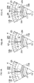
- FIG. 3A and FIG. 3B are views for describing the flow of the base oil that is contained in the grease G.
- FIG. 3A is an enlarged sectional view illustrating main portions in FIG. 1 .
- FIG. 3B is a sectional view obtained by cutting the rolling bearing unit 1 along the line IIIb-IIIb in FIG. 3A .
- the annular groove 14 of the rolling bearing 3 is filled with the grease G for initial lubrication. Further, the grease reservoir 25 is filled with the grease G for replenishment. The grease G in the annular groove 14 and the grease G in the grease reservoir 25 are connected to each other. Thus, as the base oil of the grease G in the annular groove 14 is consumed due to operation of the rolling bearing 3, the base oil of the grease G in the grease reservoir 25 moves through the grease G toward the rolling bearing 3.
- the channels 28 are formed in the grease G in the grease reservoir 25, and the end faces 30 of the grease G are exposed to the channels 28.
- the base oil of the grease G is supplied from the end faces 30 exposed to the channels 28 prior to the supply of the base oil of the grease G from the region of the grease G, which faces the opening 24.
- the base oil is consumed from the end faces 30 side of the grease G, and thus the end faces 30 are recessed.
- the channels 28 expand, that is, the channels 28 bulge on respective sides (refer to FIG. 3B ).
- the channels 28 are formed over the entire range from the opening 24 of the grease reservoir 25 to the bottom-side flange 22 of the oil reserving ring 18 (refer to FIG. 3B ) in the axial direction X of the outer ring spacer 16. Further, the channels 28 are formed over the entire range from the cylindrical portion 21 of the oil reserving ring 18 to the peripheral wall 19 of the outer ring spacer 16 (refer to FIG. 2 ) in the radial direction of the outer ring spacer 16.
- the surface area of each end face 30 is maximized in the grease reservoir 25 having a limited size. As a result, the flow of the base oil from the bottom side of the grease reservoir 25 toward the opening 24 in the axial direction X of the outer ring spacer 16 is efficiently produced.
- the multiple channels 28 are formed in the grease G. With this configuration as well, the total surface area of the end faces 30 of the grease G is increased. As a result, the flow of the base oil from the bottom side of the grease reservoir 25 toward the opening 24 in the axial direction X of the outer ring spacer 16 is efficiently produced. Further, the grease G is completely partitioned into the multiple sections 29 by the channels 28. That is, each of the sections 29 is physically separated from the adjacent sections 29 by the channels 28. Thus, even if a crack is formed in one of the sections 29 of the grease G, development of the crack is stopped by the channels 28 that are adjacent to this section 29, and thus the crack in the grease G remains in the one section 29. As a result, the sections 29 adjacent to the cracked section 29 are not influenced by the crack in the grease G in the cracked section 29. Thus, it is possible to continuously supply the base oil in the grease G.
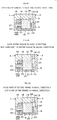
- FIG. 4A to FIG. 4C are sectional views of the rolling bearing unit 1, for sequentially describing steps related to formation of the channels 28 in the grease G illustrated in FIG. 2 .
- the channels 28 in the grease G are formed according to, for example, the steps illustrated in FIG. 4A to FIG. 4C .
- the inner ring spacer 15, and the outer ring spacer 16 and the oil reserving ring 18 are fitted to each other to assemble the grease reserving member 4, and then, as illustrated in FIG.
- spacers 31 are inserted into the grease reservoir 25 through the through-holes 26 (for example, the first through-holes 26L) from the back side of the outer ring spacer 16 (on the opposite side of the outer ring spacer 16 from the grease reservoir 25).
- Each spacer 31 is formed in a shape corresponding to the shape of each channel 28, and the shape of each spacer 31 is designed in advance.
- the grease G is supplied into the grease reservoir 25 through the opening 24.
- the grease G is supplied into the grease reservoir 25 except the spaces occupied by the spacers 31.
- the spacers 31 are pulled out toward the back side of the outer ring spacer 16 through the through-holes 26 through which the spacers 31 are inserted.
- the channels 28 that partition the grease G into the sections 29 are defined in the spaces in which the spacers 31 are occupied before being pulled out.
- the channels 28 are formed in the grease G through a simple work in which the spacers 31 are inserted into and pulled out from the grease reservoir 25. While the example embodiment of the invention has been described above, the invention may be implemented in various other embodiments. For example, in the above-described embodiment, as illustrated in FIG. 5A , the channels 28 are formed over the entire range from the opening 24 of the grease reservoir 25 to the bottom-side flange 22 of the oil reserving ring 18 in the axial direction of the outer ring spacer 16, and are formed over the entire range from the cylindrical portion 21 of the oil reserving ring 18 to the peripheral wall 19 of the outer ring spacer 16 in the radial direction of the outer ring spacer 16. However, as illustrated in, for example, FIG.
- the channels 28 may be formed in the radial direction of the outer ring spacer 16, over only a part of the entire range (for example, from the peripheral wall 19 of the outer ring spacer 16 to a position apart from the cylindrical portion 21 of the oil reserving ring 18, that is, the channels 28 are apart from the cylindrical portion 21 of the oil reserving ring 18) although the channels 28 are formed over the entire range in the axial direction of the outer ring spacer 16. As illustrated in, for example, FIG.
- the channels 28 may be formed in the axial direction of the outer ring spacer 16 over only a part of the entire range (for example, from the opening 24 of the grease reservoir 25 to a position apart from the bottom-side flange 22 of the oil reserving ring 18, that is, the channels 28 are apart from the bottom-side flange 22 of the oil reserving ring 18) although the channels 28 are formed over the entire range in the radial direction of the outer ring spacer 16.
- the annular and continuous grease reservoir 25 is adopted in the above-described embodiment.
- the grease reservoir 25 may be partitioned into multiple chambers along the circumferential direction of the outer ring spacer 16.
- the inner ring 5 and the inner ring spacer 15 are rotary members that are rotated together with the main spindle 2 whereas the outer ring 6 and the outer ring spacer 16 are stationary members that are secured to the housing (not illustrated).
- the invention may be also applied to a case in which the outer ring 6 and the outer ring spacer 16 are rotary members, whereas the inner ring 5 and the inner ring spacer 15 are stationary members.
Landscapes
- Engineering & Computer Science (AREA)
- General Engineering & Computer Science (AREA)
- Mechanical Engineering (AREA)
- Rolling Contact Bearings (AREA)
Claims (5)
- Unité de palier à roulement (1) comprenant :un palier à roulement (3) comprenant une bague interne (5) une bague externe (6) et une pluralité d'éléments de roulement (7) disposés entre la bague interne (5) et la bague externe (6) ;un dispositif d'espacement annulaire (15, 16) disposé de manière adjacente à une extrémité axiale du palier à roulement (3), le dispositif d'espacement annulaire ayant un réservoir de graisse (25) se présentant sous la forme d'une rainure s'étendant le long d'une direction circonférentielle du dispositif d'espacement annulaire, et un passage d'écoulement qui fournit la communication entre le réservoir de graisse (25) et un intérieur du palier à roulement (3) ;au moins un dispositif d'espacement (31) ; etla graisse retenue dans le réservoir de graisse (25), caractérisée par :au moins un canal (28) qui est formé en retirant le au moins un dispositif d'espacement (31) dans la graisse pour s'étendre à partir du passage d'écoulement le long d'une direction axiale du dispositif d'espacement annulaire, de sorte que l'huile de base de la graisse (G) est alimentée, de plus, à partir des faces d'extrémité (30) de la graisse exposée au canal (28).
- Unité de palier à roulement (1) selon la revendication 1, dans laquelle :une pluralité de canaux (28) sont formés dans la graisse ; etles canaux (28) sont positionnés à intervalles le long de la direction circonférentielle du dispositif d'espacement annulaire.
- Unité de palier à roulement (1) selon la revendication 1 ou 2, dans laquelle le canal (28) est formé sur toute une plage allant du passage d'écoulement à une partie inférieure du réservoir de graisse (25) dans la direction axiale du dispositif d'espacement annulaire.
- Unité de palier à roulement (1) selon l'une quelconque des revendications 1 à 3, dans laquelle le canal (28) est formé sur toute une plage allant du réservoir de graisse (25) dans une direction radiale du dispositif annulaire, la graisse étant séparée en plusieurs sections (29) par le canal.
- Procédé pour produire une unité de palier à roulement (1) selon l'une quelconque des revendications 1 à 4, dans lequel le canal (28) est formé par l'étape suivante :utiliser au moins un dispositif d'espacement (31) disposé dans le réservoir de graisse pour s'étendre le long d'une direction axiale du dispositif d'espacement annulaire ; etretirer le au moins un dispositif d'espacement (31) après que la graisse a été alimentée.
Applications Claiming Priority (1)
| Application Number | Priority Date | Filing Date | Title |
|---|---|---|---|
| JP2013165303A JP6414656B2 (ja) | 2013-08-08 | 2013-08-08 | 転がり軸受装置および転がり軸受装置の製造方法 |
Publications (3)
| Publication Number | Publication Date |
|---|---|
| EP2835546A2 EP2835546A2 (fr) | 2015-02-11 |
| EP2835546A3 EP2835546A3 (fr) | 2015-06-24 |
| EP2835546B1 true EP2835546B1 (fr) | 2017-12-20 |
Family
ID=51298592
Family Applications (1)
| Application Number | Title | Priority Date | Filing Date |
|---|---|---|---|
| EP14180225.6A Not-in-force EP2835546B1 (fr) | 2013-08-08 | 2014-08-07 | Unité de palier à roulement avec réservoir de graisse |
Country Status (4)
| Country | Link |
|---|---|
| US (1) | US9169873B2 (fr) |
| EP (1) | EP2835546B1 (fr) |
| JP (1) | JP6414656B2 (fr) |
| CN (1) | CN104343824B (fr) |
Families Citing this family (4)
| Publication number | Priority date | Publication date | Assignee | Title |
|---|---|---|---|---|
| US9933016B2 (en) | 2014-04-15 | 2018-04-03 | Jtekt Corporation | Rolling bearing device |
| JP6390399B2 (ja) * | 2014-12-11 | 2018-09-19 | 株式会社ジェイテクト | 転がり軸受装置、転がり軸受装置の製造方法、及び治具 |
| GB201500700D0 (en) | 2015-01-16 | 2015-03-04 | Rolls Royce Plc | Rolling-element bearing and method of countering load applied to rolling-element bearing |
| JP7362239B2 (ja) * | 2018-02-13 | 2023-10-17 | Ntn株式会社 | 軸受装置およびスピンドル装置 |
Family Cites Families (14)
| Publication number | Priority date | Publication date | Assignee | Title |
|---|---|---|---|---|
| US3019065A (en) | 1959-11-09 | 1962-01-30 | Howard B Neeley | Grease container |
| JPH07269573A (ja) * | 1994-03-31 | 1995-10-17 | Ntn Corp | 針状ころ軸受 |
| JPH08294247A (ja) * | 1995-04-21 | 1996-11-05 | Toshiba Corp | 回転電機の軸受装置 |
| JPH0923607A (ja) * | 1995-07-06 | 1997-01-21 | Toshiba Corp | 軸受装置 |
| JP4199850B2 (ja) * | 1998-07-14 | 2008-12-24 | 日本トムソン株式会社 | 潤滑プレートを備えた直動案内ユニット |
| JP2003194074A (ja) * | 2001-12-26 | 2003-07-09 | Nsk Ltd | 軸受装置の潤滑機構 |
| JP2005106245A (ja) * | 2003-10-01 | 2005-04-21 | Ntn Corp | 潤滑機構付き軸受およびそれを用いた工作機械用スピンドル装置 |
| JP2005180629A (ja) | 2003-12-22 | 2005-07-07 | Ntn Corp | 転がり軸受 |
| DE112005002505T5 (de) * | 2004-10-08 | 2007-09-06 | Ntn Corp. | Wälzlager |
| JP2006226427A (ja) * | 2005-02-18 | 2006-08-31 | Ntn Corp | 転がり軸受 |
| JP2007078115A (ja) * | 2005-09-15 | 2007-03-29 | Ntn Corp | 転がり軸受 |
| US7874733B2 (en) * | 2006-01-05 | 2011-01-25 | Ntn Corporation | Rolling bearing |
| WO2010010897A1 (fr) * | 2008-07-25 | 2010-01-28 | 株式会社ジェイテクト | Dispositif de palier à roulement, et procédé de formation de moyens de lubrification pour le dispositif |
| WO2011102303A1 (fr) * | 2010-02-17 | 2011-08-25 | Ntn株式会社 | Structure de lubrification pour palier à roulement, et palier à roulement |
-
2013
- 2013-08-08 JP JP2013165303A patent/JP6414656B2/ja not_active Expired - Fee Related
-
2014
- 2014-07-31 US US14/448,518 patent/US9169873B2/en not_active Expired - Fee Related
- 2014-08-07 EP EP14180225.6A patent/EP2835546B1/fr not_active Not-in-force
- 2014-08-08 CN CN201410387942.XA patent/CN104343824B/zh not_active Expired - Fee Related
Non-Patent Citations (1)
| Title |
|---|
| None * |
Also Published As
| Publication number | Publication date |
|---|---|
| US9169873B2 (en) | 2015-10-27 |
| EP2835546A3 (fr) | 2015-06-24 |
| EP2835546A2 (fr) | 2015-02-11 |
| CN104343824A (zh) | 2015-02-11 |
| JP2015034587A (ja) | 2015-02-19 |
| JP6414656B2 (ja) | 2018-10-31 |
| CN104343824B (zh) | 2018-08-07 |
| US20150043853A1 (en) | 2015-02-12 |
Similar Documents
| Publication | Publication Date | Title |
|---|---|---|
| EP2835546B1 (fr) | Unité de palier à roulement avec réservoir de graisse | |
| US8439570B2 (en) | Rolling bearing assembly and method of forming a lubrication device therefor | |
| EP2386772B1 (fr) | Roulement à rouleaux avec lubrification interne | |
| WO2016010057A1 (fr) | Roulement à billes | |
| US20140050430A1 (en) | Bearing and lubrication system used therewith | |
| EP3296594B1 (fr) | Vis à billes | |
| US9933016B2 (en) | Rolling bearing device | |
| US9291204B2 (en) | Rolling bearing with a lateral filling opening | |
| JP4941134B2 (ja) | 直動ねじ装置 | |
| CN103380306A (zh) | 具有内部润滑的滚动轴承 | |
| CN103758873A (zh) | 一种脂润滑密封轴承 | |
| EP2781777B1 (fr) | Unité de palier à roulement | |
| JP2005180629A (ja) | 転がり軸受 | |
| JP2006226427A (ja) | 転がり軸受 | |
| JP2006234072A (ja) | 転がり軸受 | |
| TWI719234B (zh) | 滾珠軸承及工具機用主軸裝置 | |
| CN105545961A (zh) | 一种低噪音的深沟球轴承 | |
| JP6390399B2 (ja) | 転がり軸受装置、転がり軸受装置の製造方法、及び治具 | |
| JP2005299757A (ja) | 転がり軸受 | |
| JP2007120698A (ja) | 転がり軸受 | |
| JP2010002027A (ja) | 円筒ころ軸受および円筒ころ軸受装置 | |
| JP6414663B2 (ja) | 転がり軸受装置 | |
| JP2016065571A (ja) | 軸受装置 | |
| JP5120488B2 (ja) | 直動ねじ装置 | |
| JP2012026546A (ja) | ボールスプライン |
Legal Events
| Date | Code | Title | Description |
|---|---|---|---|
| PUAI | Public reference made under article 153(3) epc to a published international application that has entered the european phase |
Free format text: ORIGINAL CODE: 0009012 |
|
| 17P | Request for examination filed |
Effective date: 20140807 |
|
| AK | Designated contracting states |
Kind code of ref document: A2 Designated state(s): AL AT BE BG CH CY CZ DE DK EE ES FI FR GB GR HR HU IE IS IT LI LT LU LV MC MK MT NL NO PL PT RO RS SE SI SK SM TR |
|
| AX | Request for extension of the european patent |
Extension state: BA ME |
|
| PUAL | Search report despatched |
Free format text: ORIGINAL CODE: 0009013 |
|
| AK | Designated contracting states |
Kind code of ref document: A3 Designated state(s): AL AT BE BG CH CY CZ DE DK EE ES FI FR GB GR HR HU IE IS IT LI LT LU LV MC MK MT NL NO PL PT RO RS SE SI SK SM TR |
|
| AX | Request for extension of the european patent |
Extension state: BA ME |
|
| RIC1 | Information provided on ipc code assigned before grant |
Ipc: F16C 33/66 20060101AFI20150520BHEP |
|
| R17P | Request for examination filed (corrected) |
Effective date: 20151105 |
|
| RBV | Designated contracting states (corrected) |
Designated state(s): AL AT BE BG CH CY CZ DE DK EE ES FI FR GB GR HR HU IE IS IT LI LT LU LV MC MK MT NL NO PL PT RO RS SE SI SK SM TR |
|
| GRAP | Despatch of communication of intention to grant a patent |
Free format text: ORIGINAL CODE: EPIDOSNIGR1 |
|
| INTG | Intention to grant announced |
Effective date: 20170613 |
|
| GRAS | Grant fee paid |
Free format text: ORIGINAL CODE: EPIDOSNIGR3 |
|
| GRAA | (expected) grant |
Free format text: ORIGINAL CODE: 0009210 |
|
| AK | Designated contracting states |
Kind code of ref document: B1 Designated state(s): AL AT BE BG CH CY CZ DE DK EE ES FI FR GB GR HR HU IE IS IT LI LT LU LV MC MK MT NL NO PL PT RO RS SE SI SK SM TR |
|
| REG | Reference to a national code |
Ref country code: GB Ref legal event code: FG4D |
|
| REG | Reference to a national code |
Ref country code: CH Ref legal event code: EP |
|
| REG | Reference to a national code |
Ref country code: IE Ref legal event code: FG4D |
|
| REG | Reference to a national code |
Ref country code: AT Ref legal event code: REF Ref document number: 956666 Country of ref document: AT Kind code of ref document: T Effective date: 20180115 |
|
| REG | Reference to a national code |
Ref country code: DE Ref legal event code: R096 Ref document number: 602014018673 Country of ref document: DE |
|
| REG | Reference to a national code |
Ref country code: NL Ref legal event code: MP Effective date: 20171220 |
|
| PG25 | Lapsed in a contracting state [announced via postgrant information from national office to epo] |
Ref country code: SE Free format text: LAPSE BECAUSE OF FAILURE TO SUBMIT A TRANSLATION OF THE DESCRIPTION OR TO PAY THE FEE WITHIN THE PRESCRIBED TIME-LIMIT Effective date: 20171220 Ref country code: FI Free format text: LAPSE BECAUSE OF FAILURE TO SUBMIT A TRANSLATION OF THE DESCRIPTION OR TO PAY THE FEE WITHIN THE PRESCRIBED TIME-LIMIT Effective date: 20171220 Ref country code: LT Free format text: LAPSE BECAUSE OF FAILURE TO SUBMIT A TRANSLATION OF THE DESCRIPTION OR TO PAY THE FEE WITHIN THE PRESCRIBED TIME-LIMIT Effective date: 20171220 Ref country code: NO Free format text: LAPSE BECAUSE OF FAILURE TO SUBMIT A TRANSLATION OF THE DESCRIPTION OR TO PAY THE FEE WITHIN THE PRESCRIBED TIME-LIMIT Effective date: 20180320 |
|
| REG | Reference to a national code |
Ref country code: LT Ref legal event code: MG4D |
|
| REG | Reference to a national code |
Ref country code: AT Ref legal event code: MK05 Ref document number: 956666 Country of ref document: AT Kind code of ref document: T Effective date: 20171220 |
|
| PG25 | Lapsed in a contracting state [announced via postgrant information from national office to epo] |
Ref country code: HR Free format text: LAPSE BECAUSE OF FAILURE TO SUBMIT A TRANSLATION OF THE DESCRIPTION OR TO PAY THE FEE WITHIN THE PRESCRIBED TIME-LIMIT Effective date: 20171220 Ref country code: RS Free format text: LAPSE BECAUSE OF FAILURE TO SUBMIT A TRANSLATION OF THE DESCRIPTION OR TO PAY THE FEE WITHIN THE PRESCRIBED TIME-LIMIT Effective date: 20171220 Ref country code: GR Free format text: LAPSE BECAUSE OF FAILURE TO SUBMIT A TRANSLATION OF THE DESCRIPTION OR TO PAY THE FEE WITHIN THE PRESCRIBED TIME-LIMIT Effective date: 20180321 Ref country code: LV Free format text: LAPSE BECAUSE OF FAILURE TO SUBMIT A TRANSLATION OF THE DESCRIPTION OR TO PAY THE FEE WITHIN THE PRESCRIBED TIME-LIMIT Effective date: 20171220 Ref country code: BG Free format text: LAPSE BECAUSE OF FAILURE TO SUBMIT A TRANSLATION OF THE DESCRIPTION OR TO PAY THE FEE WITHIN THE PRESCRIBED TIME-LIMIT Effective date: 20180320 |
|
| PG25 | Lapsed in a contracting state [announced via postgrant information from national office to epo] |
Ref country code: NL Free format text: LAPSE BECAUSE OF FAILURE TO SUBMIT A TRANSLATION OF THE DESCRIPTION OR TO PAY THE FEE WITHIN THE PRESCRIBED TIME-LIMIT Effective date: 20171220 |
|
| PG25 | Lapsed in a contracting state [announced via postgrant information from national office to epo] |
Ref country code: ES Free format text: LAPSE BECAUSE OF FAILURE TO SUBMIT A TRANSLATION OF THE DESCRIPTION OR TO PAY THE FEE WITHIN THE PRESCRIBED TIME-LIMIT Effective date: 20171220 Ref country code: SK Free format text: LAPSE BECAUSE OF FAILURE TO SUBMIT A TRANSLATION OF THE DESCRIPTION OR TO PAY THE FEE WITHIN THE PRESCRIBED TIME-LIMIT Effective date: 20171220 Ref country code: CZ Free format text: LAPSE BECAUSE OF FAILURE TO SUBMIT A TRANSLATION OF THE DESCRIPTION OR TO PAY THE FEE WITHIN THE PRESCRIBED TIME-LIMIT Effective date: 20171220 Ref country code: EE Free format text: LAPSE BECAUSE OF FAILURE TO SUBMIT A TRANSLATION OF THE DESCRIPTION OR TO PAY THE FEE WITHIN THE PRESCRIBED TIME-LIMIT Effective date: 20171220 Ref country code: CY Free format text: LAPSE BECAUSE OF FAILURE TO SUBMIT A TRANSLATION OF THE DESCRIPTION OR TO PAY THE FEE WITHIN THE PRESCRIBED TIME-LIMIT Effective date: 20171220 |
|
| PG25 | Lapsed in a contracting state [announced via postgrant information from national office to epo] |
Ref country code: PL Free format text: LAPSE BECAUSE OF FAILURE TO SUBMIT A TRANSLATION OF THE DESCRIPTION OR TO PAY THE FEE WITHIN THE PRESCRIBED TIME-LIMIT Effective date: 20171220 Ref country code: IT Free format text: LAPSE BECAUSE OF FAILURE TO SUBMIT A TRANSLATION OF THE DESCRIPTION OR TO PAY THE FEE WITHIN THE PRESCRIBED TIME-LIMIT Effective date: 20171220 Ref country code: RO Free format text: LAPSE BECAUSE OF FAILURE TO SUBMIT A TRANSLATION OF THE DESCRIPTION OR TO PAY THE FEE WITHIN THE PRESCRIBED TIME-LIMIT Effective date: 20171220 Ref country code: IS Free format text: LAPSE BECAUSE OF FAILURE TO SUBMIT A TRANSLATION OF THE DESCRIPTION OR TO PAY THE FEE WITHIN THE PRESCRIBED TIME-LIMIT Effective date: 20180420 Ref country code: SM Free format text: LAPSE BECAUSE OF FAILURE TO SUBMIT A TRANSLATION OF THE DESCRIPTION OR TO PAY THE FEE WITHIN THE PRESCRIBED TIME-LIMIT Effective date: 20171220 Ref country code: AT Free format text: LAPSE BECAUSE OF FAILURE TO SUBMIT A TRANSLATION OF THE DESCRIPTION OR TO PAY THE FEE WITHIN THE PRESCRIBED TIME-LIMIT Effective date: 20171220 |
|
| REG | Reference to a national code |
Ref country code: DE Ref legal event code: R097 Ref document number: 602014018673 Country of ref document: DE |
|
| PLBE | No opposition filed within time limit |
Free format text: ORIGINAL CODE: 0009261 |
|
| STAA | Information on the status of an ep patent application or granted ep patent |
Free format text: STATUS: NO OPPOSITION FILED WITHIN TIME LIMIT |
|
| 26N | No opposition filed |
Effective date: 20180921 |
|
| PG25 | Lapsed in a contracting state [announced via postgrant information from national office to epo] |
Ref country code: DK Free format text: LAPSE BECAUSE OF FAILURE TO SUBMIT A TRANSLATION OF THE DESCRIPTION OR TO PAY THE FEE WITHIN THE PRESCRIBED TIME-LIMIT Effective date: 20171220 |
|
| PG25 | Lapsed in a contracting state [announced via postgrant information from national office to epo] |
Ref country code: SI Free format text: LAPSE BECAUSE OF FAILURE TO SUBMIT A TRANSLATION OF THE DESCRIPTION OR TO PAY THE FEE WITHIN THE PRESCRIBED TIME-LIMIT Effective date: 20171220 |
|
| PG25 | Lapsed in a contracting state [announced via postgrant information from national office to epo] |
Ref country code: MC Free format text: LAPSE BECAUSE OF FAILURE TO SUBMIT A TRANSLATION OF THE DESCRIPTION OR TO PAY THE FEE WITHIN THE PRESCRIBED TIME-LIMIT Effective date: 20171220 |
|
| REG | Reference to a national code |
Ref country code: CH Ref legal event code: PL |
|
| GBPC | Gb: european patent ceased through non-payment of renewal fee |
Effective date: 20180807 |
|
| PG25 | Lapsed in a contracting state [announced via postgrant information from national office to epo] |
Ref country code: LU Free format text: LAPSE BECAUSE OF NON-PAYMENT OF DUE FEES Effective date: 20180807 Ref country code: CH Free format text: LAPSE BECAUSE OF NON-PAYMENT OF DUE FEES Effective date: 20180831 Ref country code: LI Free format text: LAPSE BECAUSE OF NON-PAYMENT OF DUE FEES Effective date: 20180831 |
|
| REG | Reference to a national code |
Ref country code: BE Ref legal event code: MM Effective date: 20180831 |
|
| REG | Reference to a national code |
Ref country code: IE Ref legal event code: MM4A |
|
| PG25 | Lapsed in a contracting state [announced via postgrant information from national office to epo] |
Ref country code: IE Free format text: LAPSE BECAUSE OF NON-PAYMENT OF DUE FEES Effective date: 20180807 |
|
| PG25 | Lapsed in a contracting state [announced via postgrant information from national office to epo] |
Ref country code: FR Free format text: LAPSE BECAUSE OF NON-PAYMENT OF DUE FEES Effective date: 20180831 Ref country code: BE Free format text: LAPSE BECAUSE OF NON-PAYMENT OF DUE FEES Effective date: 20180831 |
|
| PG25 | Lapsed in a contracting state [announced via postgrant information from national office to epo] |
Ref country code: GB Free format text: LAPSE BECAUSE OF NON-PAYMENT OF DUE FEES Effective date: 20180807 |
|
| PG25 | Lapsed in a contracting state [announced via postgrant information from national office to epo] |
Ref country code: MT Free format text: LAPSE BECAUSE OF NON-PAYMENT OF DUE FEES Effective date: 20180807 |
|
| PG25 | Lapsed in a contracting state [announced via postgrant information from national office to epo] |
Ref country code: TR Free format text: LAPSE BECAUSE OF FAILURE TO SUBMIT A TRANSLATION OF THE DESCRIPTION OR TO PAY THE FEE WITHIN THE PRESCRIBED TIME-LIMIT Effective date: 20171220 |
|
| PG25 | Lapsed in a contracting state [announced via postgrant information from national office to epo] |
Ref country code: PT Free format text: LAPSE BECAUSE OF FAILURE TO SUBMIT A TRANSLATION OF THE DESCRIPTION OR TO PAY THE FEE WITHIN THE PRESCRIBED TIME-LIMIT Effective date: 20171220 Ref country code: HU Free format text: LAPSE BECAUSE OF FAILURE TO SUBMIT A TRANSLATION OF THE DESCRIPTION OR TO PAY THE FEE WITHIN THE PRESCRIBED TIME-LIMIT; INVALID AB INITIO Effective date: 20140807 |
|
| PG25 | Lapsed in a contracting state [announced via postgrant information from national office to epo] |
Ref country code: MK Free format text: LAPSE BECAUSE OF NON-PAYMENT OF DUE FEES Effective date: 20171220 |
|
| PG25 | Lapsed in a contracting state [announced via postgrant information from national office to epo] |
Ref country code: AL Free format text: LAPSE BECAUSE OF FAILURE TO SUBMIT A TRANSLATION OF THE DESCRIPTION OR TO PAY THE FEE WITHIN THE PRESCRIBED TIME-LIMIT Effective date: 20171220 |
|
| PGFP | Annual fee paid to national office [announced via postgrant information from national office to epo] |
Ref country code: DE Payment date: 20200729 Year of fee payment: 7 |
|
| REG | Reference to a national code |
Ref country code: DE Ref legal event code: R119 Ref document number: 602014018673 Country of ref document: DE |
|
| PG25 | Lapsed in a contracting state [announced via postgrant information from national office to epo] |
Ref country code: DE Free format text: LAPSE BECAUSE OF NON-PAYMENT OF DUE FEES Effective date: 20220301 |