EP2832207B1 - Silageverdichtungseinrichtung - Google Patents
Silageverdichtungseinrichtung Download PDFInfo
- Publication number
- EP2832207B1 EP2832207B1 EP14178549.3A EP14178549A EP2832207B1 EP 2832207 B1 EP2832207 B1 EP 2832207B1 EP 14178549 A EP14178549 A EP 14178549A EP 2832207 B1 EP2832207 B1 EP 2832207B1
- Authority
- EP
- European Patent Office
- Prior art keywords
- compression device
- silage
- edge
- lever
- carrier
- Prior art date
- Legal status (The legal status is an assumption and is not a legal conclusion. Google has not performed a legal analysis and makes no representation as to the accuracy of the status listed.)
- Active
Links
- 239000004460 silage Substances 0.000 title claims description 60
- 230000006835 compression Effects 0.000 title claims description 39
- 238000007906 compression Methods 0.000 title claims description 39
- 238000005056 compaction Methods 0.000 description 35
- 244000025254 Cannabis sativa Species 0.000 description 2
- 241001148470 aerobic bacillus Species 0.000 description 2
- 240000008042 Zea mays Species 0.000 description 1
- 235000016383 Zea mays subsp huehuetenangensis Nutrition 0.000 description 1
- 235000002017 Zea mays subsp mays Nutrition 0.000 description 1
- 150000002148 esters Chemical class 0.000 description 1
- 230000002349 favourable effect Effects 0.000 description 1
- 235000009973 maize Nutrition 0.000 description 1
- 238000004519 manufacturing process Methods 0.000 description 1
- 230000004083 survival effect Effects 0.000 description 1
- XLYOFNOQVPJJNP-UHFFFAOYSA-N water Substances O XLYOFNOQVPJJNP-UHFFFAOYSA-N 0.000 description 1
Images
Classifications
-
- A—HUMAN NECESSITIES
- A01—AGRICULTURE; FORESTRY; ANIMAL HUSBANDRY; HUNTING; TRAPPING; FISHING
- A01F—PROCESSING OF HARVESTED PRODUCE; HAY OR STRAW PRESSES; DEVICES FOR STORING AGRICULTURAL OR HORTICULTURAL PRODUCE
- A01F25/00—Storing agricultural or horticultural produce; Hanging-up harvested fruit
- A01F25/16—Arrangements in forage silos
- A01F25/18—Loading or distributing arrangements
- A01F25/183—Loading arrangements
Definitions
- the invention relates to an silage compaction device, which can be picked up and operated by a tractor, according to the preamble of claim 1.
- a tractor with such silage compaction device is used to silage, such as grass or maize, which is piled up into a silo, especially clearing pile to condense. To do this, the tractor drives the silage.
- the silage is compacted from above by means of the tires of the tractor and by means of the silage compaction device.
- a compression pressure is provided by the weight of the tractor. This weight can be increased by filling the tires with water.
- Silageverdichtungs nails have a compressor roller whose axis of rotation is aligned horizontally. This results in a compaction of the silage from above.
- the compacting of silage with a tractor and such a known silage compaction device requires a lot of skill and driving skills by the driver of the tractor.
- edges of the silo can only be compacted incompletely or not at all. Therefore, larger air pockets remain at the edges of the silo where aerobic bacteria can cause mold growth.
- a silo feeding device which achieves a higher compression on the sides of the silo by laterally angled arranged tires.
- this known Silo-loading device is designed as a stand-alone vehicle, which would not be suitable for transport by a tractor on a road also due to its width Out DE 10 2006 012 851 B1
- a silage compactor is known, which is also designed as a stand-alone vehicle. Lateral compressor rolls of this known silage compactor can be extended laterally and subsequently lowered by a separate mechanism. The width of the silage compactor can thus be reduced if no lateral compression takes place by means of the lateral compressor rolls. The lateral extension and lowering of the lateral compressor rollers is cumbersome.
- the silage compaction device has at least one edge compacting device articulated to a support by means of a pivot axis, the edge compacting device being opposite to the carrier in FIG a working position is pivotable, in which the edge compacting device for compacting a side edge of a silo is sloping sloping to its outer side facing away from the pivot axis, and is pivotable into a transport position, in which the Kantenverdichtungsvorides is employed to its outside, and the Silageverdichtungs shark has pivot means for pivoting the Edge compacting device from the working position to the transport position and from the transport position to the working position, wherein the pivot means according to the invention for Pr eat the edge compaction device in the working position against the side edge of the silo, serve.
- the silage compaction device can be picked up and operated by a known tractor, in particular a roller tractor.
- the carrier is formed in one or more parts.
- the pivot axis is in particular a rotary joint.
- a component is hinged to another component, these components are preferably connected to each other via a hinge or hinge.
- the pivoting between the working position and the transport position takes place about an axis given by the rotary joint.
- This axis is at least approximately horizontal and aligned in the direction of travel of the tractor when the silage compaction device is picked up by the tractor.
- the invention allows an advantageous compression of the silage at the edge of the silo to be built.
- the width of the silage compaction device is reduced compared to possible positions of the edge compacting device in the working position.
- the width of the silage compaction device according to the invention with the edge compaction device in the transport position is less than the width of the optionally equipped with twin tires tractor or no wider than a conventional tractor-receivable silage compaction device with a conventional, acting on top of the silage compressor roller.
- the pivot means on a first lever which is hinged to the edge compacting device.
- the edge compacting device can be pivoted.
- the pivot means also have a second lever, which is articulated on the first lever.
- this second lever is pivotable relative to the first carrier.
- the second lever is articulated on the carrier or on a component which is fixed relative to the carrier. Via the second lever, the first lever can be moved and thus the edge compacting device can be pivoted.
- the pivot means comprise at least one hydraulic cylinder.
- the hydraulic cylinder is preferably articulated on the one hand on a fixed position relative to the carrier, in particular on the carrier itself, and on the other hand articulated on the second lever.
- the edge compacting device can be pivoted by at least 90 degrees. More preferably, the edge compacting device may be more than 90 degrees, more than 120 degrees, more than 150 degrees or even 180 degrees.
- the lengths of the first lever and of the second lever are dimensioned relative to the distances of their articulation points on the carrier or on the edge compacting device to the articulation point of the edge compacting device on the carrier that this respective pivoting range is achieved. Thanks to this large pivoting range, a transport position can be achieved, in which the silage compaction device assumes an advantageously small width.
- the edge compacting device comprises a tire packer roller.
- the tire packer roller has a plurality of tires lined up on an axle, which are rotatably mounted.
- the tractor with the silage compaction device drives over the silo and thereby the tire packer roller is pressed against the edge of the silo, rotate the tires or rotates the tire packer roller.
- the tire packer roller allows a cost-effective manner a favorable pressure transfer to the silo.
- the edge compacting device has a pivot arm articulated to the carrier to which the tire packer roller is rotatably mounted.
- the ends of an axis of the tire packer roller are mounted on the swivel arm. Thanks to the carrier, the tire packer roller is always held securely on the swivel arm even after pivoting in any achievable orientation.
- the swivel arm preferably provides a secure point of articulation for the first lever.
- the silage compaction device has a vertical compaction device.
- the vertical compacting device is understood to mean a device for compacting the silo on its flat upper side or from above. For a compression of the silo from above and at least one side edge with the silage compaction device according to the invention in one operation is possible.
- the vertical compacting device preferably has a compacting roller.
- the vertical compacting device is designed as a compacting roller.
- the compressor roller is aligned for the compression of the silo from above horizontally transversely to the direction of travel of the silage compaction device receiving tractor and has a in this case substantially horizontally oriented axis of rotation.
- the edge compacting device is aligned in the transport position perpendicular to the vertical compacting device.
- the axes of rotation of the compressor roller and the tire packer roller are aligned perpendicular to each other in the transport position.
- this vertical orientation is to be understood as an orientation at an angle of 90 degrees or approximately 90 degrees to one another, wherein the edge compacting device and the vertical compacting device are also present at a relative angle between 80 degrees and 100 degrees, in particular between 70 degrees and 110 degrees relative to one another be considered perpendicular to each other.
- the edge compacting device Due to the substantially horizontal pivot axis, with which the edge compacting device is articulated on the carrier, the edge compacting device is vertically or approximately vertically aligned in the transport position when properly recorded on the tractor. In vertical alignment, the edge compacting device can be transported to save space.
- an at least partially laterally acting pressing pressure can be applied by means of the pivoting means for at least partially sideways pressing of the edge compacting device against the side edge of the silo.
- the pressing force on the side edge of the silo thus not only a vertical, but also a horizontal component.
- a particularly advantageous compression is achieved.
- the silage compaction device has a hydraulic connection.
- the hydraulic connection is used for releasable connection to a hydraulic circuit of the tractor for operation of the pivot means by means of this hydraulic circuit.
- the silage compaction device can thus be operated by a hydraulic unit of the tractor. A separate own drive The silage compaction device is therefore dispensable.
- the hydraulic cylinder is supplied or controlled by the hydraulic circuit of the tractor.
- a pressure relief valve is also provided, which preferably limits a hydraulic pressure provided via the hydraulic connection.
- the hydraulic pressure on the silage compaction device is limited to 50 bar.
- a controllable control valve is provided, by means of which any settable hydraulic pressure can be applied to the hydraulic cylinder.
- the contact pressure of the tire packer roller to the side edge of the silo can thus be controlled individually.
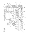
- Fig. 1 shows a tractor 1 with a rear side of the tractor 1 recorded Silageverdichtungs Road 2 according to an embodiment of the invention.
- a carrier 3 of the silage compaction device 2 is detachably connected to a conventional hydraulically lowerable device at the rear of the tractor 1.
- a hydraulic connection 4 of the silage compaction device 2 is connected to a hydraulic connection of the tractor 1 in order to be operated by a hydraulic unit of the tractor 1.
- a vertical compression device 5 in the form of a compressor roller 6 is rotatably supported about a horizontally oriented axis.
- a pivot arm 7 is articulated by means of a pivot axis 8 about this pivot axis 8 pivotally on the carrier 3.
- the pivot arm 7 is part of an edge compacting device 9, which has a tire packer roller 10 carried by the pivot arm 7 with a plurality of rotatably mounted tires.
- the edge compacting device 9 is shown in a transport position 11, in which the axis of rotation of the tire packer roller 10 is aligned substantially vertically and perpendicular to the axis of rotation of the compactor roller 6.
- the edge compacting device 9 is thus set to its outer side 12.
- the silage compaction device 2 has pivoting means 13 with a hydraulic cylinder 14 controlled via the hydraulic connection 4, with a first lever 15 and with a second lever 16.
- the second lever 16 is pivoted at a defined distance from the pivot axis 8 on the carrier 3.
- the second lever 16 and the pivot arm 7 are articulated by means of further joints at opposite ends of the first lever 15.
- the respective distances of the connecting joints are selected such that a pivoting movement of the second lever 16 caused by the hydraulic cylinder 14 is converted via the first lever 15 into a comparatively larger pivoting movement of the pivoting arm 7.
- the invention thereby achieves a swivel angle of the swivel arm 7 by 180 degrees.
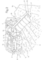
- Fig. 2 shows a section of the silage compaction device of the embodiment according to Fig. 1
- the tractor 1 is located on the flat top of a silo 17, which is constructed, for example, grass free-standing.
- the compressor roller 6 rests on the silo 17 and compresses the silage used for the production of the silo 17 from above.
- the tire packer roller 10 is pressed by means of the pivoting means 13 against the silage and compacts the silo on the side edge 18.
- a pressing pressure is applied perpendicular to the axis of rotation of the tire packer roller 10 on the silo 17.
- the Kantenverdichtungsvorettiopathy 9 is in its working position in which it is sloping sloping to its outer side 12.
- the pressing pressure has a horizontal portion, so that the silo 17 at the side edge 18 not only from above, but also is compressed sideways. As a result, a particularly advantageous compaction of the silage of the silo 17 is achieved. Aerobic bacteria is thus deprived of the basis of survival, so that the emergence of mold esters is effectively counteracted.
Landscapes
- Life Sciences & Earth Sciences (AREA)
- Environmental Sciences (AREA)
- Storage Of Harvested Produce (AREA)
Description
- Die Erfindung betrifft eine Silageverdichtungseinrichtung, die von einem Schlepper aufgenommen und betrieben werden kann, nach dem Oberbegriff des Anspruches 1. Ein Schlepper mit einer derartigen Silageverdichtungseinrichtung wird dazu eingesetzt, Silage, wie Gras oder Mais, die zu einem Silo, insbesondere Freigärhaufen, aufgeschichtet ist, zu verdichten. Hierzu befährt der Schlepper die Silage. Dabei wird die Silage mittels der Reifen des Schleppers sowie mittels der Silageverdichtungseinrichtung von oben verdichtet. Ein Verdichtungsdruck wird dabei durch das Eigengewicht des Schleppers bereitgestellt. Dieses Eigengewicht kann durch Befüllen der Reifen mit Wasser erhöht werden.
- Bekannte derartige Silageverdichtungseinrichtungen weisen eine Verdichterwalze auf, deren Drehachse horizontal ausgerichtet ist. Damit erfolgt eine Verdichtung der Silage von oben. Das Verdichten von Silage mit einem Schlepper und einer derartigen bekannten Silageverdichtungseinrichtung erfordert viel Geschick und fahrerisches Können durch den Fahrer des Schleppers. Dennoch können Ränder des Silos nur unvollständig oder überhaupt nicht verdichtet werden. Daher verbleiben an den Rändern des Silos größere Lufteinschlüsse, an denen aerobe Bakterien Schimmelbildung verursachen können.
- Aus
DE 195 37 085 A1 ist eine Silobeschickungsvorrichtung bekannt, die durch seitlich abgewinkelt angeordnete Reifen zwar eine höhere Verdichtung an den Seiten des Silos erreicht. Jedoch ist diese bekannte Silobeschickungseinrichtung als eigenständiges Fahrzeug ausgebildet, das auch aufgrund seiner Breite nicht zum Transport durch einen Schlepper auf einer Straße geeignet wäre AusDE 10 2006 012 851 B1 ist ferner ein Silageverdichter bekannt, der ebenfalls als eigenständiges Fahrzeug ausgebildet ist. Seitliche Verdichterwalzen dieses bekannten Silageverdichters können seitlich ausgefahren und durch einen separaten Mechanismus nachfolgend abgesenkt werden. Die Breite des Silageverdichters kann somit verringert werden, wenn keine seitliche Verdichtung mittels der seitlichen Verdichterwalzen erfolgt. Das seitliche Ausfahren und Absenken der seitlichen Verdichterwalzen ist jedoch umständlich. - Der Erfindung liegt nach alledem die Aufgabe zugrunde, bei einer Silageverdichtungseinrichtung, die von einem Schlepper aufnehmbar und betreibbar ist, die Verdichtung an zumindest einer Seite eines Silos zu verbessern.
- Die Erfindung löst diese Aufgabe mit einer Silageverdichtungseinrichtung nach Anspruch 1. Bei einer Silageverdichtungseinrichtung, die von einem Schlepper aufnehmbar und betreibbar ist, ist vorgesehen, dass die Silageverdichtungseinrichtung wenigstens eine mittels einer Schwenkachse an einem Träger angelenkte Kantenverdichtungsvorrichtung aufweist, wobei die Kantenverdichtungsvorrichtung gegenüber dem Träger in eine Arbeitsstellung schwenkbar ist, in der die Kantenverdichtungsvorrichtung zum Verdichten eines Seitenrandes eines Silos zu ihrer der Schwenkachse abgewandten Außenseite abfallend geneigt ist, und in eine Transportstellung schwenkbar ist, in der die Kantenverdichtungsvorrichtung zu ihrer Außenseite angestellt ist, und die Silageverdichtungseinrichtung Schwenkmittel aufweist zum Schwenken der Kantenverdichtungsvorrichtung von der Arbeitsstellung in die Transportstellung und von der Transportstellung in die Arbeitsstellung, wobei die Schwenkmittel erfindungsgemäß zum Pressen der Kantenverdichtungsvorrichtung in der Arbeitsstellung gegen den Seitenrand des Silos, dienen.
- Die Silageverdichtungseinrichtung kann von einem bekannten Schlepper, insbesondere Walzschlepper, aufgenommen und betrieben werden. Der Träger ist einteilig oder mehrteilig ausgebildet. Die Schwenkachse ist insbesondere ein Drehgelenk. In allen Fällen, in denen gemäß dieser Anmeldung ein Bauteil an einem anderen Bauteil angelenkt ist, sind diese Bauteile vorzugsweise über ein Drehgelenk bzw. Scharnier miteinander verbunden.
- Das Schwenken zwischen der Arbeitsstellung und der Transportstellung erfolgt um eine durch das Drehgelenk gegebene Achse. Diese Achse ist zumindest näherungsweise horizontal und in Fahrtrichtung des Schleppers ausgerichtet, wenn die Silageverdichtungseinrichtung vom Schlepper aufgenommen ist.
- In der Arbeitsstellung ermöglicht die Erfindung eine vorteilhafte Verpressung der Silage am Rand des aufzubauenden Silos. In der Transportstellung ist die Breite der Silageverdichtungseinrichtung gegenüber möglichen Positionen der Kantenverdichtungsvorrichtung in der Arbeitsstellung verringert. Insbesondere ist die Breite der erfindungsgemäßen Silageverdichtungseinrichtung mit der Kantenverdichtungsvorrichtung in der Transportstellung geringer als die Breite des gegebenenfalls mit Zwillingsreifen ausgerüsteten Schleppers oder nicht breiter als eine herkömmliche von einem Schlepper aufnehmbare Silageverdichtungseinrichtung mit einer herkömmlichen, von oben auf die Silage wirkenden Verdichterwalze.
- Gemäß einer vorteilhaften Ausführungsform weisen die Schwenkmittel einen ersten Hebel auf, der an der Kantenverdichtungsvorrichtung angelenkt ist. Mittels dieses ersten Hebels kann die Kantenverdichtungsvorrichtung verschwenkt werden. Gemäß einer vorteilhaften Weiterbildung dieser Ausführungsform weisen die Schwenkmittel auch einen zweiten Hebel auf, der am ersten Hebel angelenkt ist. Vorteilhafterweise ist dieser zweite Hebel gegenüber dem ersten Träger verschwenkbar. Insbesondere ist der zweite Hebel am Träger oder an einem Bauteil, welches fest relativ zum Träger fixiert ist, angelenkt. Über den zweiten Hebel kann der erste Hebel bewegt und damit die Kantenverdichtungsvorrichtung verschwenkt werden.
- Gemäß einer bevorzugten Ausführungsform weisen die Schwenkmittel wenigstens einen Hydraulikzylinder auf. Der Hydraulikzylinder ist vorzugsweise einerseits an einer relativ zum Träger festen Position, insbesondere am Träger selbst, angelenkt und andererseits am zweiten Hebel angelenkt. Mittels des Hydraulikzylinders kann somit der zweite Hebel verschwenkt und damit über den ersten Hebel die Kantenverdichtungsvorrichtung verschwenkt werden. Vorzugsweise kann die Kantenverdichtungsvorrichtung um mindestens 90 Grad verschwenkt werden. Besonders bevorzugt kann die Kantenverdichtungsvorrichtung um mehr als 90 Grad, mehr als 120 Grad, mehr als 150 Grad oder sogar um 180 Grad verschwenkt werden. Insbesondere sind die Längen des ersten Hebels und des zweiten Hebels derart relativ zu den Abständen ihrer Anlenkpunkte am Träger bzw. an der Kantenverdichtungsvorrichtung zum Anlenkpunkt der Kantenverdichtungsvorrichtung am Träger bemessen, dass dieser jeweilige Schwenkbereich erreicht wird. Dank dieses großen Schwenkbereiches kann eine Transportstellung erreicht werden, in welcher die Silageverdichtungseinrichtung eine vorteilhaft geringe Breite einnimmt.
- Gemäß einer bevorzugten Ausführungsform weist die Kantenverdichtungsvorrichtung eine Reifenpackerwalze auf. Die Reifenpackerwalze weist mehrere an einer Achse aufgereihte Reifen auf, die drehbar gelagert sind. Wenn der Schlepper mit der Silageverdichtungseinrichtung über das Silo fährt und dabei die Reifenpackerwalze gegen den Rand des Silos gepresst wird, drehen sich die Reifen bzw. dreht sich die Reifenpackerwalze. Die Reifenpackerwalze ermöglicht auf kostengünstige Weise eine vorteilhafte Druckübermittlung auf das Silo.
- Gemäß einer vorteilhaften Ausführungsform weist die Kantenverdichtungsvorrichtung einen am Träger angelenkten Schwenkarm auf, an dem die Reifenpackerwalze drehbar befestigt ist. Insbesondere sind am Schwenkarm die Enden einer Achse der Reifenpackerwalze gelagert. Dank des Trägers ist die Reifenpackerwalze auch nach einem Verschwenken in jede erreichbare Ausrichtung immer sicher am Schwenkarm gehalten. Zudem stellt der Schwenkarm vorzugsweise einen sicheren Anlenkpunkt für den ersten Hebel bereit.
- Gemäß einer bevorzugten Ausführungsform weist die Silageverdichtungseinrichtung eine Vertikalverdichtungsvorrichtung auf. Unter der Vertikalverdichtungsvorrichtung ist eine Vorrichtung zum Verdichten des Silos an seiner flächigen Oberseite oder von oben zu verstehen. Damit ist ein Verdichten des Silos von oben und an wenigstens einem Seitenrand mit der erfindungsgemäßen Silageverdichtungseinrichtung in einem Arbeitsgang möglich.
- Vorzugsweise weist die Vertikalverdichtungsvorrichtung eine Verdichterwalze auf. Insbesondere ist die Vertikalverdichtungsvorrichtung als Verdichterwalze ausgebildet.
- Die Verdichterwalze ist für die Verdichtung des Silos von oben horizontal quer zur Fahrtrichtung des die Silageverdichtungseinrichtung aufnehmenden Schleppers ausgerichtet und weist eine in diesem Fall im Wesentlichen horizontal ausgerichtete Drehachse auf.
- Gemäß einer bevorzugten Ausführungsform ist die Kantenverdichtungsvorrichtung in der Transportstellung senkrecht zur Vertikalverdichtungsvorrichtung ausgerichtet. Insbesondere sind die Drehachsen der Verdichterwalze und der Reifenpackerwalze in der Transportstellung senkrecht zueinander ausgerichtet. Unter dieser senkrechten Ausrichtung ist vorliegend eine Ausrichtung in einem Winkel von 90 Grad oder ungefähr 90 Grad zueinander zu verstehen, wobei die Kantenverdichtungsvorrichtung und die Vertikalverdichtungsvorrichtung vorliegend auch bei einem relativen Winkel zwischen 80 Grad und 100 Grad, insbesondere zwischen 70 Grad und 110 Grad relativ zueinander als senkrecht zueinander ausgerichtet angesehen werden. Aufgrund der im Wesentlichen horizontalen Schwenkachse, mit der die Kantenverdichtungsvorrichtung am Träger angelenkt ist, ist die Kantenverdichtungsvorrichtung in der Transportstellung bei ordnungsgemäßer Aufnahme am Schlepper vertikal oder näherungsweise vertikal ausgerichtet. In vertikaler Ausrichtung kann die Kantenverdichtungsvorrichtung platzsparend transportiert werden.
- In der Arbeitsstellung der Kantenverdichtungsvorrichtung kann mittels der Schwenkmittel ein zumindest teilweise seitlich wirkender Pressdruck aufgebracht werden zum zumindest teilweise seitwärts gerichteten Pressen der Kantenverdichtungsvorrichtung gegen den Seitenrand des Silos. Insbesondere weist die Presskraft am Seitenrand des Silos somit nicht nur eine vertikale, sondern auch eine horizontale Komponente auf. Dadurch wird eine besonders vorteilhafte Verpressung erreicht.
- Gemäß einer bevorzugten Ausführungsform weist die Silageverdichtungseinrichtung einen Hydraulikanschluss auf. Der Hydraulikanschluss dient zum lösbaren Verbinden mit einem Hydraulikkreis des Schleppers für einen Betrieb der Schwenkmittel mittels dieses Hydraulikkreises. Die Silageverdichtungseinrichtung kann somit von einem Hydraulikaggregat des Schleppers betrieben werden. Ein separater eigener Antrieb an der Silageverdichtungseinrichtung ist folglich entbehrlich. Insbesondere wird der Hydraulikzylinder vom Hydraulikkreis des Schleppers versorgt oder angesteuert.
- Gemäß einer Weiterbildung der Erfindung ist ferner ein Überdruckventil vorgesehen, das vorzugsweise einen über den Hydraulikanschluss bereitgestellten hydraulischen Druck begrenzt. Insbesondere wird der hydraulische Druck an der Silageverdichtungseinrichtung auf 50 bar begrenzt.
- Vorzugsweise ist ein ansteuerbares Steuerventil vorgesehen, mittels dem ein beliebiger bereitstellbarer hydraulischer Druck auf den Hydraulikzylinder gegeben werden kann. Der Anpressdruck der Reifenpackerwalze an den Seitenrand des Silos kann somit individuell gesteuert werden.
- Weitere Ausführungsformen ergeben sich aus den Ansprüchen sowie aus dem anhand der Zeichnungen beschriebenen Ausführungsbeispiel. In den Zeichnungen zeigen:
- Fig. 1:
- eine von einem Schlepper aufgenommene Silageverdichtungseinrichtung mit einer in Transportstellung befindlichen Kantenverdichtungsvorrichtung gemäß einem Ausführungsbeispiel der Erfindung in vereinfachter perspektivischer Darstellung, und
- Fig. 2:
- einen Teil der Silageverdichtungseinrichtung des Ausführungsbeispiels gemäß
Fig. 1 mit der in einer Arbeitsstellung befindlichen Kantenverdichtungsvorrichtung in vereinfachter perspektivischer Darstellung. -
Fig. 1 zeigt einen Schlepper 1 mit einer vom Schlepper 1 heckseitig aufgenommenen Silageverdichtungseinrichtung 2 gemäß einem Ausführungsbeispiel der Erfindung. Ein Träger 3 der Silageverdichtungseinrichtung 2 ist lösbar mit einer herkömmlichen hydraulisch absenkbaren Einrichtung am Heck des Schleppers 1 verbunden. Ferner ist zum Betrieb der Silageverdichtungseinrichtung 2 ein Hydraulikanschluss 4 der Silageverdichtungseinrichtung 2 mit einem Hydraulikanschluss des Schleppers 1 verbunden, um von einem Hydraulikaggregat des Schleppers 1 betrieben zu werden. - Am Träger 3 ist eine Vertikalverdichtungsvorrichtung 5 in Form einer Verdichterwalze 6 um eine horizontal ausgerichtete Achse drehbar gehalten. Ferner ist am Träger 3 ein Schwenkarm 7 mittels einer Schwenkachse 8 um diese Schwenkachse 8 verschwenkbar angelenkt. Der Schwenkarm 7 ist Teil einer Kantenverdichtungsvorrichtung 9, die eine vom Schwenkarm 7 getragene Reifenpackerwalze 10 mit mehreren drehbar gelagerten Reifen aufweist. Die Kantenverdichtungsvorrichtung 9 ist in einer Transportstellung 11 dargestellt, in der die Drehachse der Reifenpackerwalze 10 im Wesentlichen vertikal sowie senkrecht zur Drehachse der Verdichterwalze 6 ausgerichtet ist. Die Kantenverdichtungsvorrichtung 9 ist somit zu ihrer Außenseite 12 angestellt.
- Die Silageverdichtungseinrichtung 2 weist Schwenkmittel 13 mit einem über den Hydraulikanschluss 4 angesteuerten Hydraulikzylinder 14, mit einem ersten Hebel 15 und mit einem zweiten Hebel 16 auf. Der zweite Hebel 16 ist in einem definierten Abstand von der Schwenkachse 8 schwenkbar am Träger 3 angelenkt. Ferner sind der zweite Hebel 16 und der Schwenkarm 7 mittels weiterer Gelenke an gegenüberliegende Enden des ersten Hebels 15 angelenkt. Die jeweiligen Abstände der verbindenden Gelenke sind derart gewählt, dass eine mittels des Hydraulikzylinders 14 verursachte Schwenkbewegung des zweiten Hebels 16 über den ersten Hebel 15 in eine vergleichsweise größere Schwenkbewegung des Schwenkarmes 7 umgesetzt wird. Die Erfindung erreicht dadurch einen Schwenkwinkel des Schwenkarmes 7 um 180 Grad.
-
Fig. 2 zeigt einen Ausschnitt der Silageverdichtungseinrichtung des Ausführungsbeispiels gemäßFig. 1 , aufgenommen und betrieben vom Schlepper 1. Der Schlepper 1 befindet sich auf der flachen Oberseite eines Silos 17, welches beispielsweise aus Gras freistehend aufgebaut wird. Die Verdichterwalze 6 liegt dabei auf dem Silo 17 auf und verdichtet die zur Herstellung des Silos 17 verwendete Silage von oben. Am Seitenrand 18 des Silos 17 wird die Reifenpackerwalze 10 mittels der Schwenkmittel 13 gegen die Silage gedrückt und verdichtet das Silo am Seitenrand 18. Ein Pressdruck wird dabei senkrecht zur Drehachse der Reifenpackerwalze 10 auf das Silo 17 ausgeübt. Die Kantenverdichtungsvorrichtung 9 befindet sich in ihrer Arbeitsstellung, in der sie zu ihrer Außenseite 12 abfallend geneigt ist. Der Pressdruck weist dabei einen horizontalen Anteil auf, so dass das Silo 17 am Seitenrand 18 nicht nur von oben, sondern auch seitwärts verdichtet wird. Dadurch wird eine besonders vorteilhafte Verdichtung der Silage des Silos 17 erreicht. Aeroben Bakterien wird dadurch die Überlebensgrundlage entzogen, so dass einem Entstehen von Schimmelnestern wirkungsvoll entgegengewirkt ist. - Alle in der vorstehenden Beschreibung und in den Ansprüchen genannten Merkmale sind in einer beliebigen Auswahl mit den Merkmalen des unabhängigen Anspruchs kombinierbar. Die Offenbarung der Erfindung ist somit nicht auf die beschriebenen Merkmalskombinationen beschränkt, vielmehr sind alle im Rahmen der beanspruchten Merkmalskombinationen als offenbart zu betrachten.
Claims (11)
- Silageverdichtungseinrichtung mit wenigstens einer mittels einer Schwenkachse (8) an einem Träger (3) angelenkte Kantenverdichtungsvorrichtung (9), wobei die Kantenverdichtungsvorrichtung (9) gegenüber dem Träger (3) in eine Arbeitsstellung (19) schwenkbar ist, in der die Kantenverdichtungsvorrichtung (9) zum Verdichten eines Seitenrandes (18) eines Silos (17) zu ihrer der Schwenkachse (8) abgewandten Außenseite (12) abfallend geneigt ist, und in eine Transportstellung (11) schwenkbar ist, in der die Kantenverdichtungsvorrichtung (9) zu ihrer Außenseite (12) angestellt ist, und die Silageverdichtungseinrichtung (2) Schwenkmittel (13) aufweist zum Schwenken der Kantenverdichtungsvorrichtung (9) von der Arbeitsstellung (19) in die Transportstellung (11) und von der Transportstellung (11) in die Arbeitsstellung (19),
dadurch gekennzeichnet,
dass die Schwenkmittel (13) dem Pressen der Kantenverdichtungsvorrichtung (9) in der Arbeitsstellung (19) gegen den Seitenrand (18) des Silos (17) dienen. - Silageverdichtungseinrichtung nach Anspruch 1, dadurch gekennzeichnet, dass die Schwenkmittel (13) einen ersten Hebel (15) aufweisen, der an der Kantenverdichtungsvorrichtung (9) angelenkt ist und einen zweiten Hebel (16) aufweisen, der am ersten Hebel (15) angelenkt ist und der gegenüber dem Träger (3) verschwenkbar ist.
- Silageverdichtungseinrichtung nach Anspruch 2, dadurch gekennzeichnet, dass die Schwenkmittel (13) wenigstens einen Hydraulikzylinder (14) aufweisen, der einerseits am Träger (3) und andererseits am zweiten Hebel (16) angelenkt ist.
- Silageverdichtungseinrichtung nach einem der vorherigen Ansprüche, dadurch gekennzeichnet, dass die Kantenverdichtungsvorrichtung (9) um mindestens 90 Grad, insbesondere um mehr als 90 Grad, mehr als 120 Grad, mehr als 150 Grad oder 180 Grad, verschwenkbar ist.
- Silageverdichtungseinrichtung nach einem der vorherigen Ansprüche, dadurch gekennzeichnet, dass die Kantenverdichtungsvorrichtung (9) eine Reifenpackerwalze (10) aufweist.
- Silageverdichtungseinrichtung nach Anspruch 5, dadurch gekennzeichnet, dass die Kantenverdichtungsvorrichtung (9) einen zum Träger (3) angelenkten Schwenkarm (7) aufweist, an dem die Reifenpackerwalze (10) drehbar befestigt ist.
- Silageverdichtungseinrichtung nach einem der vorherigen Ansprüche, dadurch gekennzeichnet, dass die Silageverdichtungseinrichtung (2) eine Vertikalverdichtungsvorrichtung (5) aufweist.
- Silageverdichtungseinrichtung nach Anspruch 7, dadurch gekennzeichnet, dass die Vertikalverdichtungsvorrichtung (5) eine Verdichterwalze (6) aufweist.
- Silageverdichtungseinrichtung nach Anspruch 7 oder 8, dadurch gekennzeichnet, dass die Kantenverdichtungsvorrichtung (9) in der Transportstellung (11) senkrecht zur Vertikalverdichtungsvorrichtung (5) ausgerichtet ist.
- Silageverdichtungseinrichtung nach einem der vorherigen Ansprüche, dadurch gekennzeichnet, dass in der Arbeitsstellung (19) der Kantenverdichtungsvorrichtung (9) mittels der Schwenkmittel (13) ein zumindest teilweise seitlich wirkender Pressdruck aufbringbar ist zum zumindest teilweise seitwärts gerichteten Pressen der Kantenverdichtungsvorrichtung (9) gegen den Seitenrand (18) des Silos (17).
- Silageverdichtungseinrichtung nach einem der vorherigen Ansprüche, dadurch gekennzeichnet, dass die Silageverdichtungseinrichtung (2) einen Hydraulikanschluss (4) aufweist zum lösbaren Verbinden mit einem Hydraulikkreis eines Schleppers (1) für einen Betrieb der Schwenkmittel (13) mittels dieses Hydraulikkreises.
Applications Claiming Priority (1)
| Application Number | Priority Date | Filing Date | Title |
|---|---|---|---|
| DE201320006860 DE202013006860U1 (de) | 2013-07-31 | 2013-07-31 | Silageverdichtungseinrichtung |
Publications (2)
| Publication Number | Publication Date |
|---|---|
| EP2832207A1 EP2832207A1 (de) | 2015-02-04 |
| EP2832207B1 true EP2832207B1 (de) | 2016-11-09 |
Family
ID=49232553
Family Applications (1)
| Application Number | Title | Priority Date | Filing Date |
|---|---|---|---|
| EP14178549.3A Active EP2832207B1 (de) | 2013-07-31 | 2014-07-25 | Silageverdichtungseinrichtung |
Country Status (2)
| Country | Link |
|---|---|
| EP (1) | EP2832207B1 (de) |
| DE (1) | DE202013006860U1 (de) |
Families Citing this family (3)
| Publication number | Priority date | Publication date | Assignee | Title |
|---|---|---|---|---|
| US11076626B2 (en) | 2019-03-05 | 2021-08-03 | Cnh Industrial America Llc | System and method for distributing and compressing crop material for ensilage |
| US11199845B2 (en) | 2019-03-05 | 2021-12-14 | Cnh Industrial America Llc | System and method for distributing and compressing crop material for ensilage |
| US11247426B2 (en) * | 2020-04-07 | 2022-02-15 | Deere & Company | Oscillating silage compactor |
Family Cites Families (3)
| Publication number | Priority date | Publication date | Assignee | Title |
|---|---|---|---|---|
| DE19537085A1 (de) | 1995-10-05 | 1997-04-10 | Stotz Gmbh & Co Kg M | Silobeschickungsvorrichtung |
| DE102006012851B3 (de) | 2006-03-21 | 2007-08-30 | Knut Ehlers | Silageverdichter |
| DE202010006957U1 (de) * | 2010-05-19 | 2010-08-05 | Stehr, Jürgen | Silageverdichter |
-
2013
- 2013-07-31 DE DE201320006860 patent/DE202013006860U1/de not_active Expired - Lifetime
-
2014
- 2014-07-25 EP EP14178549.3A patent/EP2832207B1/de active Active
Also Published As
| Publication number | Publication date |
|---|---|
| DE202013006860U1 (de) | 2013-08-23 |
| EP2832207A1 (de) | 2015-02-04 |
Similar Documents
| Publication | Publication Date | Title |
|---|---|---|
| DE602004009666T2 (de) | Rundballenpresse | |
| EP2832207B1 (de) | Silageverdichtungseinrichtung | |
| DE3025235C2 (de) | ||
| EP3224037B1 (de) | Transportabler rollenverdichter | |
| WO2018114652A1 (de) | Wurzelballen-unterschneide- und aushebegerät | |
| DE102016008822A1 (de) | Mobilkran mit verstellbarer Ballastaufnahmevorrichtung | |
| EP0771522B1 (de) | Ballenpresse | |
| EP1062860A2 (de) | Zuführkanal für ein Erntefahrzeug, insbesondere für eine landwirtschaftliche Aufsammelballenpresse | |
| EP1588601B1 (de) | Erntemaschine mit einer Austrageinrichtung | |
| EP1062859B1 (de) | Ballenpresse | |
| EP1825742B1 (de) | Verfahren und Vorrichtung zum Verdichten von abgeerntetem Erntegut zur Silageerzeugung | |
| EP3014978B1 (de) | Rundballenpresse mit ballenwickler | |
| DE102009017400A1 (de) | Erntemaschine | |
| DE2934154C2 (de) | Fahrbare Maschine zum Beladen und Fördern losen Materials | |
| DE202007017616U1 (de) | Verfahrbare Vorrichtung zum Verdichten von Müll und zur Beförderung von Transportbehältern | |
| DE202021104388U1 (de) | Vorrichtung zur Ausbringung von Gülle | |
| EP3926096A1 (de) | Bodenverdichtungsvorrichtung zur verdichtung einer untergrundbelagsschicht, asphaltwalze und verfahren zum betrieb einer bodenverdichtungsvorrichtung | |
| DE102011111251A1 (de) | Landmaschine | |
| DE102012102084A1 (de) | Verlade- und Transportvorrichtung für landwirtschaftliche Schneidwerke | |
| DE2902500A1 (de) | Feldhaecksler | |
| DE202007012649U1 (de) | Ladewagen | |
| AT413174B (de) | Rückeschild | |
| DE202009008528U1 (de) | Selbstfahrender Holzhäcksler | |
| DE202010000352U1 (de) | Anbaugerät | |
| AT505831B1 (de) | Loipenspurgerät |
Legal Events
| Date | Code | Title | Description |
|---|---|---|---|
| 17P | Request for examination filed |
Effective date: 20140725 |
|
| AK | Designated contracting states |
Kind code of ref document: A1 Designated state(s): AL AT BE BG CH CY CZ DE DK EE ES FI FR GB GR HR HU IE IS IT LI LT LU LV MC MK MT NL NO PL PT RO RS SE SI SK SM TR |
|
| AX | Request for extension of the european patent |
Extension state: BA ME |
|
| PUAI | Public reference made under article 153(3) epc to a published international application that has entered the european phase |
Free format text: ORIGINAL CODE: 0009012 |
|
| R17P | Request for examination filed (corrected) |
Effective date: 20150609 |
|
| RBV | Designated contracting states (corrected) |
Designated state(s): AL AT BE BG CH CY CZ DE DK EE ES FI FR GB GR HR HU IE IS IT LI LT LU LV MC MK MT NL NO PL PT RO RS SE SI SK SM TR |
|
| GRAP | Despatch of communication of intention to grant a patent |
Free format text: ORIGINAL CODE: EPIDOSNIGR1 |
|
| INTG | Intention to grant announced |
Effective date: 20160603 |
|
| GRAS | Grant fee paid |
Free format text: ORIGINAL CODE: EPIDOSNIGR3 |
|
| GRAA | (expected) grant |
Free format text: ORIGINAL CODE: 0009210 |
|
| AK | Designated contracting states |
Kind code of ref document: B1 Designated state(s): AL AT BE BG CH CY CZ DE DK EE ES FI FR GB GR HR HU IE IS IT LI LT LU LV MC MK MT NL NO PL PT RO RS SE SI SK SM TR |
|
| REG | Reference to a national code |
Ref country code: GB Ref legal event code: FG4D Free format text: NOT ENGLISH |
|
| REG | Reference to a national code |
Ref country code: AT Ref legal event code: REF Ref document number: 843008 Country of ref document: AT Kind code of ref document: T Effective date: 20161115 Ref country code: CH Ref legal event code: EP |
|
| REG | Reference to a national code |
Ref country code: IE Ref legal event code: FG4D Free format text: LANGUAGE OF EP DOCUMENT: GERMAN |
|
| REG | Reference to a national code |
Ref country code: DE Ref legal event code: R096 Ref document number: 502014001898 Country of ref document: DE |
|
| REG | Reference to a national code |
Ref country code: NL Ref legal event code: FP |
|
| PG25 | Lapsed in a contracting state [announced via postgrant information from national office to epo] |
Ref country code: LV Free format text: LAPSE BECAUSE OF FAILURE TO SUBMIT A TRANSLATION OF THE DESCRIPTION OR TO PAY THE FEE WITHIN THE PRESCRIBED TIME-LIMIT Effective date: 20161109 |
|
| REG | Reference to a national code |
Ref country code: LT Ref legal event code: MG4D |
|
| PG25 | Lapsed in a contracting state [announced via postgrant information from national office to epo] |
Ref country code: SE Free format text: LAPSE BECAUSE OF FAILURE TO SUBMIT A TRANSLATION OF THE DESCRIPTION OR TO PAY THE FEE WITHIN THE PRESCRIBED TIME-LIMIT Effective date: 20161109 Ref country code: GR Free format text: LAPSE BECAUSE OF FAILURE TO SUBMIT A TRANSLATION OF THE DESCRIPTION OR TO PAY THE FEE WITHIN THE PRESCRIBED TIME-LIMIT Effective date: 20170210 Ref country code: LT Free format text: LAPSE BECAUSE OF FAILURE TO SUBMIT A TRANSLATION OF THE DESCRIPTION OR TO PAY THE FEE WITHIN THE PRESCRIBED TIME-LIMIT Effective date: 20161109 Ref country code: NO Free format text: LAPSE BECAUSE OF FAILURE TO SUBMIT A TRANSLATION OF THE DESCRIPTION OR TO PAY THE FEE WITHIN THE PRESCRIBED TIME-LIMIT Effective date: 20170209 |
|
| PG25 | Lapsed in a contracting state [announced via postgrant information from national office to epo] |
Ref country code: HR Free format text: LAPSE BECAUSE OF FAILURE TO SUBMIT A TRANSLATION OF THE DESCRIPTION OR TO PAY THE FEE WITHIN THE PRESCRIBED TIME-LIMIT Effective date: 20161109 Ref country code: ES Free format text: LAPSE BECAUSE OF FAILURE TO SUBMIT A TRANSLATION OF THE DESCRIPTION OR TO PAY THE FEE WITHIN THE PRESCRIBED TIME-LIMIT Effective date: 20161109 Ref country code: RS Free format text: LAPSE BECAUSE OF FAILURE TO SUBMIT A TRANSLATION OF THE DESCRIPTION OR TO PAY THE FEE WITHIN THE PRESCRIBED TIME-LIMIT Effective date: 20161109 Ref country code: FI Free format text: LAPSE BECAUSE OF FAILURE TO SUBMIT A TRANSLATION OF THE DESCRIPTION OR TO PAY THE FEE WITHIN THE PRESCRIBED TIME-LIMIT Effective date: 20161109 Ref country code: IS Free format text: LAPSE BECAUSE OF FAILURE TO SUBMIT A TRANSLATION OF THE DESCRIPTION OR TO PAY THE FEE WITHIN THE PRESCRIBED TIME-LIMIT Effective date: 20170309 Ref country code: PT Free format text: LAPSE BECAUSE OF FAILURE TO SUBMIT A TRANSLATION OF THE DESCRIPTION OR TO PAY THE FEE WITHIN THE PRESCRIBED TIME-LIMIT Effective date: 20170309 Ref country code: PL Free format text: LAPSE BECAUSE OF FAILURE TO SUBMIT A TRANSLATION OF THE DESCRIPTION OR TO PAY THE FEE WITHIN THE PRESCRIBED TIME-LIMIT Effective date: 20161109 |
|
| PG25 | Lapsed in a contracting state [announced via postgrant information from national office to epo] |
Ref country code: RO Free format text: LAPSE BECAUSE OF FAILURE TO SUBMIT A TRANSLATION OF THE DESCRIPTION OR TO PAY THE FEE WITHIN THE PRESCRIBED TIME-LIMIT Effective date: 20161109 Ref country code: EE Free format text: LAPSE BECAUSE OF FAILURE TO SUBMIT A TRANSLATION OF THE DESCRIPTION OR TO PAY THE FEE WITHIN THE PRESCRIBED TIME-LIMIT Effective date: 20161109 Ref country code: DK Free format text: LAPSE BECAUSE OF FAILURE TO SUBMIT A TRANSLATION OF THE DESCRIPTION OR TO PAY THE FEE WITHIN THE PRESCRIBED TIME-LIMIT Effective date: 20161109 Ref country code: SK Free format text: LAPSE BECAUSE OF FAILURE TO SUBMIT A TRANSLATION OF THE DESCRIPTION OR TO PAY THE FEE WITHIN THE PRESCRIBED TIME-LIMIT Effective date: 20161109 Ref country code: CZ Free format text: LAPSE BECAUSE OF FAILURE TO SUBMIT A TRANSLATION OF THE DESCRIPTION OR TO PAY THE FEE WITHIN THE PRESCRIBED TIME-LIMIT Effective date: 20161109 |
|
| REG | Reference to a national code |
Ref country code: DE Ref legal event code: R097 Ref document number: 502014001898 Country of ref document: DE |
|
| PG25 | Lapsed in a contracting state [announced via postgrant information from national office to epo] |
Ref country code: BG Free format text: LAPSE BECAUSE OF FAILURE TO SUBMIT A TRANSLATION OF THE DESCRIPTION OR TO PAY THE FEE WITHIN THE PRESCRIBED TIME-LIMIT Effective date: 20170209 Ref country code: IT Free format text: LAPSE BECAUSE OF FAILURE TO SUBMIT A TRANSLATION OF THE DESCRIPTION OR TO PAY THE FEE WITHIN THE PRESCRIBED TIME-LIMIT Effective date: 20161109 Ref country code: SM Free format text: LAPSE BECAUSE OF FAILURE TO SUBMIT A TRANSLATION OF THE DESCRIPTION OR TO PAY THE FEE WITHIN THE PRESCRIBED TIME-LIMIT Effective date: 20161109 |
|
| PLBE | No opposition filed within time limit |
Free format text: ORIGINAL CODE: 0009261 |
|
| STAA | Information on the status of an ep patent application or granted ep patent |
Free format text: STATUS: NO OPPOSITION FILED WITHIN TIME LIMIT |
|
| 26N | No opposition filed |
Effective date: 20170810 |
|
| PG25 | Lapsed in a contracting state [announced via postgrant information from national office to epo] |
Ref country code: SI Free format text: LAPSE BECAUSE OF FAILURE TO SUBMIT A TRANSLATION OF THE DESCRIPTION OR TO PAY THE FEE WITHIN THE PRESCRIBED TIME-LIMIT Effective date: 20161109 |
|
| REG | Reference to a national code |
Ref country code: CH Ref legal event code: PL |
|
| REG | Reference to a national code |
Ref country code: IE Ref legal event code: MM4A |
|
| REG | Reference to a national code |
Ref country code: FR Ref legal event code: ST Effective date: 20180330 |
|
| PG25 | Lapsed in a contracting state [announced via postgrant information from national office to epo] |
Ref country code: LI Free format text: LAPSE BECAUSE OF NON-PAYMENT OF DUE FEES Effective date: 20170731 Ref country code: IE Free format text: LAPSE BECAUSE OF NON-PAYMENT OF DUE FEES Effective date: 20170725 Ref country code: CH Free format text: LAPSE BECAUSE OF NON-PAYMENT OF DUE FEES Effective date: 20170731 |
|
| PG25 | Lapsed in a contracting state [announced via postgrant information from national office to epo] |
Ref country code: FR Free format text: LAPSE BECAUSE OF NON-PAYMENT OF DUE FEES Effective date: 20170731 |
|
| REG | Reference to a national code |
Ref country code: BE Ref legal event code: MM Effective date: 20170731 |
|
| PG25 | Lapsed in a contracting state [announced via postgrant information from national office to epo] |
Ref country code: LU Free format text: LAPSE BECAUSE OF NON-PAYMENT OF DUE FEES Effective date: 20170725 |
|
| PG25 | Lapsed in a contracting state [announced via postgrant information from national office to epo] |
Ref country code: BE Free format text: LAPSE BECAUSE OF NON-PAYMENT OF DUE FEES Effective date: 20170731 |
|
| PG25 | Lapsed in a contracting state [announced via postgrant information from national office to epo] |
Ref country code: MT Free format text: LAPSE BECAUSE OF FAILURE TO SUBMIT A TRANSLATION OF THE DESCRIPTION OR TO PAY THE FEE WITHIN THE PRESCRIBED TIME-LIMIT Effective date: 20161109 |
|
| GBPC | Gb: european patent ceased through non-payment of renewal fee |
Effective date: 20180725 |
|
| PG25 | Lapsed in a contracting state [announced via postgrant information from national office to epo] |
Ref country code: GB Free format text: LAPSE BECAUSE OF NON-PAYMENT OF DUE FEES Effective date: 20180725 |
|
| PG25 | Lapsed in a contracting state [announced via postgrant information from national office to epo] |
Ref country code: HU Free format text: LAPSE BECAUSE OF FAILURE TO SUBMIT A TRANSLATION OF THE DESCRIPTION OR TO PAY THE FEE WITHIN THE PRESCRIBED TIME-LIMIT; INVALID AB INITIO Effective date: 20140725 Ref country code: MC Free format text: LAPSE BECAUSE OF FAILURE TO SUBMIT A TRANSLATION OF THE DESCRIPTION OR TO PAY THE FEE WITHIN THE PRESCRIBED TIME-LIMIT Effective date: 20161109 |
|
| PG25 | Lapsed in a contracting state [announced via postgrant information from national office to epo] |
Ref country code: CY Free format text: LAPSE BECAUSE OF FAILURE TO SUBMIT A TRANSLATION OF THE DESCRIPTION OR TO PAY THE FEE WITHIN THE PRESCRIBED TIME-LIMIT Effective date: 20161109 |
|
| PG25 | Lapsed in a contracting state [announced via postgrant information from national office to epo] |
Ref country code: MK Free format text: LAPSE BECAUSE OF FAILURE TO SUBMIT A TRANSLATION OF THE DESCRIPTION OR TO PAY THE FEE WITHIN THE PRESCRIBED TIME-LIMIT Effective date: 20161109 |
|
| PG25 | Lapsed in a contracting state [announced via postgrant information from national office to epo] |
Ref country code: TR Free format text: LAPSE BECAUSE OF FAILURE TO SUBMIT A TRANSLATION OF THE DESCRIPTION OR TO PAY THE FEE WITHIN THE PRESCRIBED TIME-LIMIT Effective date: 20161109 |
|
| PG25 | Lapsed in a contracting state [announced via postgrant information from national office to epo] |
Ref country code: AL Free format text: LAPSE BECAUSE OF FAILURE TO SUBMIT A TRANSLATION OF THE DESCRIPTION OR TO PAY THE FEE WITHIN THE PRESCRIBED TIME-LIMIT Effective date: 20161109 |
|
| REG | Reference to a national code |
Ref country code: AT Ref legal event code: MM01 Ref document number: 843008 Country of ref document: AT Kind code of ref document: T Effective date: 20190725 |
|
| PG25 | Lapsed in a contracting state [announced via postgrant information from national office to epo] |
Ref country code: AT Free format text: LAPSE BECAUSE OF NON-PAYMENT OF DUE FEES Effective date: 20190725 |
|
| PGFP | Annual fee paid to national office [announced via postgrant information from national office to epo] |
Ref country code: DE Payment date: 20230418 Year of fee payment: 10 |
|
| PGFP | Annual fee paid to national office [announced via postgrant information from national office to epo] |
Ref country code: NL Payment date: 20240502 Year of fee payment: 11 |