EP2830942B1 - Flugzeugküchenkühlsystem - Google Patents
Flugzeugküchenkühlsystem Download PDFInfo
- Publication number
- EP2830942B1 EP2830942B1 EP13716918.1A EP13716918A EP2830942B1 EP 2830942 B1 EP2830942 B1 EP 2830942B1 EP 13716918 A EP13716918 A EP 13716918A EP 2830942 B1 EP2830942 B1 EP 2830942B1
- Authority
- EP
- European Patent Office
- Prior art keywords
- air
- chiller
- chilled
- modular chiller
- liquid
- Prior art date
- Legal status (The legal status is an assumption and is not a legal conclusion. Google has not performed a legal analysis and makes no representation as to the accuracy of the status listed.)
- Active
Links
- 239000007788 liquid Substances 0.000 claims description 40
- 239000003507 refrigerant Substances 0.000 claims description 11
- 238000005057 refrigeration Methods 0.000 claims description 11
- XLYOFNOQVPJJNP-UHFFFAOYSA-N water Substances O XLYOFNOQVPJJNP-UHFFFAOYSA-N 0.000 claims description 4
- 239000010695 polyglycol Substances 0.000 claims description 2
- 230000037431 insertion Effects 0.000 claims 1
- 238000003780 insertion Methods 0.000 claims 1
- 238000001816 cooling Methods 0.000 description 12
- 239000002826 coolant Substances 0.000 description 8
- 235000013361 beverage Nutrition 0.000 description 5
- 235000013305 food Nutrition 0.000 description 5
- 108091035710 E-box Proteins 0.000 description 4
- 230000006835 compression Effects 0.000 description 3
- 238000007906 compression Methods 0.000 description 3
- 238000009434 installation Methods 0.000 description 3
- LYCAIKOWRPUZTN-UHFFFAOYSA-N Ethylene glycol Chemical compound OCCO LYCAIKOWRPUZTN-UHFFFAOYSA-N 0.000 description 2
- 235000012054 meals Nutrition 0.000 description 2
- 238000000034 method Methods 0.000 description 2
- 208000021825 aldosterone-producing adrenal cortex adenoma Diseases 0.000 description 1
- 230000009286 beneficial effect Effects 0.000 description 1
- 239000006227 byproduct Substances 0.000 description 1
- 239000012530 fluid Substances 0.000 description 1
- WGCNASOHLSPBMP-UHFFFAOYSA-N hydroxyacetaldehyde Natural products OCC=O WGCNASOHLSPBMP-UHFFFAOYSA-N 0.000 description 1
- 239000011159 matrix material Substances 0.000 description 1
- 239000000203 mixture Substances 0.000 description 1
- 238000012986 modification Methods 0.000 description 1
- 230000004048 modification Effects 0.000 description 1
- 230000008707 rearrangement Effects 0.000 description 1
- 239000013585 weight reducing agent Substances 0.000 description 1
Images


Classifications
-
- B—PERFORMING OPERATIONS; TRANSPORTING
- B64—AIRCRAFT; AVIATION; COSMONAUTICS
- B64D—EQUIPMENT FOR FITTING IN OR TO AIRCRAFT; FLIGHT SUITS; PARACHUTES; ARRANGEMENT OR MOUNTING OF POWER PLANTS OR PROPULSION TRANSMISSIONS IN AIRCRAFT
- B64D11/00—Passenger or crew accommodation; Flight-deck installations not otherwise provided for
- B64D11/04—Galleys
-
- B—PERFORMING OPERATIONS; TRANSPORTING
- B64—AIRCRAFT; AVIATION; COSMONAUTICS
- B64D—EQUIPMENT FOR FITTING IN OR TO AIRCRAFT; FLIGHT SUITS; PARACHUTES; ARRANGEMENT OR MOUNTING OF POWER PLANTS OR PROPULSION TRANSMISSIONS IN AIRCRAFT
- B64D13/00—Arrangements or adaptations of air-treatment apparatus for aircraft crew or passengers, or freight space, or structural parts of the aircraft
- B64D13/06—Arrangements or adaptations of air-treatment apparatus for aircraft crew or passengers, or freight space, or structural parts of the aircraft the air being conditioned
- B64D13/08—Arrangements or adaptations of air-treatment apparatus for aircraft crew or passengers, or freight space, or structural parts of the aircraft the air being conditioned the air being heated or cooled
-
- B—PERFORMING OPERATIONS; TRANSPORTING
- B64—AIRCRAFT; AVIATION; COSMONAUTICS
- B64D—EQUIPMENT FOR FITTING IN OR TO AIRCRAFT; FLIGHT SUITS; PARACHUTES; ARRANGEMENT OR MOUNTING OF POWER PLANTS OR PROPULSION TRANSMISSIONS IN AIRCRAFT
- B64D11/00—Passenger or crew accommodation; Flight-deck installations not otherwise provided for
- B64D11/0007—Devices specially adapted for food or beverage distribution services
-
- B—PERFORMING OPERATIONS; TRANSPORTING
- B64—AIRCRAFT; AVIATION; COSMONAUTICS
- B64D—EQUIPMENT FOR FITTING IN OR TO AIRCRAFT; FLIGHT SUITS; PARACHUTES; ARRANGEMENT OR MOUNTING OF POWER PLANTS OR PROPULSION TRANSMISSIONS IN AIRCRAFT
- B64D13/00—Arrangements or adaptations of air-treatment apparatus for aircraft crew or passengers, or freight space, or structural parts of the aircraft
- B64D13/06—Arrangements or adaptations of air-treatment apparatus for aircraft crew or passengers, or freight space, or structural parts of the aircraft the air being conditioned
- B64D2013/0603—Environmental Control Systems
- B64D2013/0629—Environmental Control Systems with subsystems for cooling food, catering or special loads
-
- F—MECHANICAL ENGINEERING; LIGHTING; HEATING; WEAPONS; BLASTING
- F25—REFRIGERATION OR COOLING; COMBINED HEATING AND REFRIGERATION SYSTEMS; HEAT PUMP SYSTEMS; MANUFACTURE OR STORAGE OF ICE; LIQUEFACTION SOLIDIFICATION OF GASES
- F25D—REFRIGERATORS; COLD ROOMS; ICE-BOXES; COOLING OR FREEZING APPARATUS NOT OTHERWISE PROVIDED FOR
- F25D15/00—Devices not covered by group F25D11/00 or F25D13/00, e.g. non-self-contained movable devices
-
- Y—GENERAL TAGGING OF NEW TECHNOLOGICAL DEVELOPMENTS; GENERAL TAGGING OF CROSS-SECTIONAL TECHNOLOGIES SPANNING OVER SEVERAL SECTIONS OF THE IPC; TECHNICAL SUBJECTS COVERED BY FORMER USPC CROSS-REFERENCE ART COLLECTIONS [XRACs] AND DIGESTS
- Y02—TECHNOLOGIES OR APPLICATIONS FOR MITIGATION OR ADAPTATION AGAINST CLIMATE CHANGE
- Y02T—CLIMATE CHANGE MITIGATION TECHNOLOGIES RELATED TO TRANSPORTATION
- Y02T50/00—Aeronautics or air transport
- Y02T50/40—Weight reduction
Definitions
- the first method utilizes a standard vapor cycle based air chillers that utilize conventional refrigerant gas compression and expansion technology to generate a secondary re-circulated chilled air loop.
- the chilled air is generally supplied and returned via thermally insulated air ducting to and from a suitable storage structure, such as a galley.
- the air chiller may be located on or in the galley or mounted in part of the aircraft airframe.
- the second method utilizes the same conventional refrigerant gas compression and expansion technology, but the cooling medium is a chilled liquid rather than a gas.
- This chilled liquid is pumped in a closed loop to and from a suitable storage structure such as a galley.
- the chilled liquid in some cases are configured as a large centralized system for the whole aircraft. In other cases, the chilled liquid can be circulated at each separate aircraft door galley complex to form a local area chilling loop, or be based on each individual galley as a standalone system.
- the liquid is passed via a control valve and electronic control system to a heat exchanger, where an electric axial (or other) fan blows or sucks air through its matrix and around and enclosed areas of the storage structure that requires chilling, for example: a galley cart bay or compartment.
- the heat exchanger fan and its control system (though not necessarily all) are grouped together to form a chilled air recirculation unit that may be fitted in or on the galley or remotely from it, or the galley complex.
- US patent application publication no. US 2005/210910 describes a cooling system for a commercial aircraft galley in which heat is transferred from a galley food cart by a point-of-use heat exchange system to a liquid cooled condenser.
- Liquid coolant for the liquid cooled condenser is circulated in a liquid coolant loop to a heat exchanger expelling heat for cooling the liquid coolant.
- the liquid coolant may be water or a mixture of water and glycol.
- a flow of cooling air from a heat exchanger cooled by the liquid cooled condenser is cycled through an air over system, through an air through system, or from a thermal convection air cooling system providing at least one cooled galley food cart surface to provide cooling. Heat may be transferred from a plurality of galley food carts to the circulating liquid coolant.
- US patent application publication no. US 2010/224726 describes a point-of-use air chiller unit for an aircraft galley cart compartment which unit comprises a generally flattened rectangular case, comprising two main surfaces having a substantially larger surface area than four remaining surfaces of the case, a condenser, a compressor, an evaporator, and an evaporator fan, wherein the condenser, compressor, and evaporator are connected in a standard refrigeration manner, and a plane parallel to the main surfaces passes through the condenser, the compressor, the evaporator, and the evaporator fan.
- US patent application publication no. US 2008/156030 describes a distributed refrigeration appliance system for use in a residential kitchen and other locations in a dwelling and includes multiple separate refrigeration appliance modules, a central cooling system and a cooling circuit.
- the system can also include one or more satellite stations having a heat exchanger and arranged for supplying chilled air to one or more refrigeration appliance modules.
- One or more refrigeration appliance modules can include a thermal cascade cooling device to cool the module to lower temperatures than the cooling circuit can attain.
- One or more refrigeration appliance modules can be refrigeration/storage modules that can provide refrigerated, unconditioned or heated storage space.
- the central cooling system can be a vapor compression system having a refrigerant circuit connecting the modules.
- a modular chiller for an aircraft galley beverage cart compartment as recited in the accompanying claims.
- This compact system is particularly suited for an aircraft galley that requires refrigerated or cooled carts or trolleys, and/or standard meal boxes, and/or chilled compartments.
- a chiller system that uses a cavity created within the area commonly separating the upper and lower portions of said aircraft galley (known as the work deck area), for the installation of a chilled liquid fed chiller module with integral air distribution ductwork, a thermoelectric device or devices (using the Peltier principle) with integral air distribution ductwork, or an air chiller fed air distribution system.
- the location of the modular chiller of the present invention plays a useful role in both the galley foot print and weight reduction, as well as the efficient distribution of chilled air around the below work deck installed trolley or cart.
- the through work deck air path, ductwork and air guiding devices are positioned for the efficient use of the chilled air to meet the certification requirements of the aircraft manufacturers.
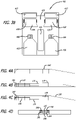
- FIGS 1a and 1 b illustrate a first preferred layout for the modular chiller of the present invention.
- a compartment 20 below the work deck of an aircraft galley houses a beverage cart 25, where the compartment is maintained at a below ambient temperature to keep the cart and its contents chilled.
- plug and play chilling module 50 comprising a heat exchanger 30 and a fan 35 arranged in a loadable cassette.
- the chiller module 50 itself is designed to comply with the requirements of rapid installation and removal of LRU's (line replaceable units) on commercial airplanes, and therefore has the major components grouped together to form a cassette or module that is fitted inside the work deck itself. Installation is carried out from the front or rear of the galley, or from inside the compartment from underneath the work deck.
- FIG. 2 illustrates a schematic of an exemplary chiller module 50.
- An electrical connector 52 is located at a first end to supply power to the chiller module 50, and a refrigerant input/output port 54 is located at the same location.
- the chilled liquid refrigerant and electric power are supplied to the chilling module 50 in a preferred embodiment via quick disconnects 52,54, while condensate is drained away at a condensate drain 56 in a similar fashion. Connection of these ports can be effected if desired only when the module 50 is installed in the compartment 20.
- the unit includes a pair of heat exchangers 30 connected to the air return ducts 40, and a pair of condensate collectors 42 capture condensate that forms on the heat exchanger/ducts.
- Each heat exchanger 30 may be equipped with a defrost fan 60, and the output of the heat exchangers 30 passes through a convergent air supply duct 62 to a tubeaxial fan 35.
- the fan 35 forces the chilled air out of the cassette 50 through air supply outlets 70 so that the air can be circulated through the compartment and chill the cart 25.
- the proportion of chilled liquid required to chill an individual cart 25 compartment is controlled by the proportioning control valves 75.
- the volume of air that needs to pass through the heat exchanger 30 is controlled by the speed of the fans 35, (which may be axial, scroll or other) under the command of the electronic control box 85 (or "E-Box").
- Sensors (not shown) provide information about the conditions within each chilled compartment to allow individual control as heat load and conditions require.
- the air (represented by arrows 90) is blown through a specially designed chilled air outlet in the underside of the module over and around the cart in the chilled cart bay before returning to be re-circulated via a specially designed duct at the back of the chilled cart bay.
- This outlet has apertures 95 that assist in creating an even air distribution around the cart.
- the duct is open at the bottom and the air return plenum 105 (or duct) mates snugly with the module air return port 40 in the chiller module when it is installed.
- FIG 3a illustrates an alternative layout to the chiller module of Figures 1 and 2 .
- the chilling module 150 (with its top removed) includes the interface port 140 to the return air plenum (or duct), and the individual heat exchangers 130 disposed at the entrance.
- the chilled liquid control (PGW distribution) valves 175 are located adjacent the heater exchangers 130.
- Poly-glycol water (“PGW”) is a one type of refrigerant that may be used with the module, although other liquid coolants may also be used.
- Figure 3b illustrates yet another alternative layout to the chiller module.
- the embodiment of Figure 3b has an entrance area 400 separates two return air inlets 410 that includes electrical, chilled liquid, and condensate drainage components.
- a three way bypass valve area 405 is disposed between two heat exchangers 420, each including a reflector 425.
- the APAC 435 is situated midline flanked by a pair of tube axial fans 440 and connected deflectors 450.
- the overall layout of the embodiment of Figure 3b results in a reduced vertical height as compared with other embodiments.
- angled condensate drainage collection trays 142 are installed below the heat exchangers with outlets in the connection block 180.
- the air is circulated around the cart bay or chilled compartments by individual axial fans 135 in this configuration, with the supply outlets 170 leading into the chilled cart bay forming an aperture in the base of the chilling module.
- the E box is located remotely on the galley and not in the chilling module itself.
- the top cover of the cassette 150 encloses all the components of the lower part to form the LRU chilling module or cassette.
- Fig 4b forms the base and cooperates with the component in Fig 4a to form the complete unit, as shown in Figure 4c.
- Figure 4d shows the rear of the chilling module 150 and its connection block 180 with the locating pin 182, chilled liquid inlet and outlet ports 184, electrical and data connectors (CANbus) 186, and the condensate drainage outlets 188.
- CANbus electrical and data connectors
- the embodiment shown in Figure 5 depicts a variation of the embodiment shown in Figures 3 and 4 where the E box 185 is installed in the chilling module 150, separate defrost fans 160 are employed, and there is a partial re-arrangement of the major components.
- the base plate mounts all major components including air supply and return ports, as well as the condensate drain.
- Figure 6 illustrates a variation of the CIWD configuration that is not covered by the appended claims, where the axial fans have been replaced by scroll or periphery fans 200, and the air is supplied to the work deck area from a conventional air chiller mounted on top of the galley.
- a conventional air chiller mounted on top of the galley.
- Air distribution is achieved using a modular ductwork 205 or by a common plenum at the rear of the work deck that mates with the chilling module.
- the chilled air return duct at the rear of the cart bay 210 connects with a return above work deck (AWD) duct 220 on the back wall of the galley, that returns the air to the air chiller.
- the chilled air supply duct 225 connects the air chiller to the distribution ductwork with the work deck area to the air chiller.
- the below work deck (BWD) chilled air return duct 210 and chilled air supply outlet 240 are similar in design to the other configurations.
- a vertical services column 245 is provided above work deck.
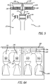
- Figures 7 and 8 show a work deck chilling system and system layout for both the air chiller supplied ( Figure 7 ) and chilled liquid supplied ( Figure 8 ) through work deck galley refrigeration systems, where the system shown in Figures 7A-D is not covered by the appended claims. .
- the schematics show the components used in the air chiller supplied Chiller In Work Deck (CIWD) system.
- 7a illustrates the over laid air supply duct 300 that leads down from the air chiller 310 on top of the galley to the common air distribution plenum.
- the air fed system differs from the liquid in that the work deck area splits to form the two halves of the ducting necessary to distribute the air between the separate cart bays.
- Balance is achieved using interchangeable tapered restrictors 320 ( Figure 7c ) to provide differing proportions of air to each cart depending on the galley configuration.
- Figure 7b illustrates the AWD (above work deck) air return duct that is mounted on the back wall of the galley. This duct 325 connects to the below work deck (BWD) chilled air return ducts 330.
- Figure 7d illustrates the position of the air chiller 310 on top of the galley, where this design utilizes a horizontal service area 340 between the standard containers (meal boxes) forming the upper storage compartments and the chilled air supply and return passes 345.
- the position of the chiller 310 in this instance is designed to meet the requirements of a center line aircraft galley. In a lateral or aft galley complex that is installed the air chiller may well be mounted below the airplane floor or behind the galley. In this case, the air distribution through the work deck is maintained although the supply and return duct work and possibly on the outside of the envelope of the galley.
- FIG. 7d also illustrates the through work deck air distribution ducting 350.
- FIG. 8a illustrates the chilled liquid supply 360 and return manifold pipe work 370 at the back of the galley chilled cart compartment, which terminates in the CIWD module interface block.
- FIG. 8b illustrates the side view of the CIWD module and cart within the compartment below the work deck.
- the present invention may include 86,4 cm (34") or 88,9 cm (35") deep refrigerated center-line galleys (installed along the centerline of the aircraft) by utilizing the work deck cavity as a means of circulating chilled air around a cart or trolley compartment.
- the invention utilizes the potential of the work deck cavity as a location to horizontally mount a refrigeration module (LRU) containing a heat exchanger, fan, fluid control valve and electronic control system that is capable of chilling the cart compartments to the required temperature using chilled liquid as a cooling medium.
- LRU refrigeration module
- the present disclosure further utilizes the potential of the work deck area as a location of duct work for distribution of chilled air produced by a vapor cycle type air chiller mounted on, in or remotely from, the galley, which is not covered by the appended claims.
Landscapes
- Engineering & Computer Science (AREA)
- Aviation & Aerospace Engineering (AREA)
- Health & Medical Sciences (AREA)
- General Health & Medical Sciences (AREA)
- Pulmonology (AREA)
- Devices That Are Associated With Refrigeration Equipment (AREA)
Claims (8)
- Modulare Kühlvorrichtung für ein Fach (20) eines Flugzeug-Bordküchenwagens, die umfasst:eine Kassette (50, 150), die eine Luft-Rückführleitung (40), einen Wärmetauscher (30, 130), ein Gebläse (35, 135, 440) und einen Luftzufuhr-Auslass (70, 170) aufnimmt;ein Steuerventil (75, 175) zum Steuern einer Menge an gekühlter Flüssigkeit, die durch den Wärmetauscher strömt; sowieeinen elektronischen Steuerkasten (85);wobei die Kassette (50, 150) abnehmbar mit einem System für gekühlte Flüssigkeit verbunden werden kann, die zum entnehmbaren Einführen in ein Wagen-Fach (20) ausgeführt ist, das unterhalb einer Arbeitsplatte des Bordküchenwagens so angeordnet ist, dass eine obere Fläche der Kassette (50, 150) unterhalb der Arbeitsplatte des Bordküchenwagens angeordnet ist und eine untere Fläche der Kassette (50, 150) so ausgeführt ist, dass sie an eine obere Fläche eines oder mehrerer Bordküchenwagens/Bordküchenwagen angeordnet ist, der/die im Inneren des Fachs (20) der Arbeitsplatte des Bordküchenwagens aufgenommen ist/sind,die modulare Kühlvorrichtung einen Eingangsanschluss (184), der lösbar zum Aufnehmen einer gekühlten Flüssigkeit von dem System für gekühlte Flüssigkeit angeschlossen werden kann, sowie einen Ausgangsanschluss (184) aufweist, der lösbar zum Zurückführen der gekühlten Flüssigkeit zu dem System für gekühlte Flüssigkeit angeschlossen werden kann, undeine Drehzahl des Gebläses (35, 135, 440) durch den elektronischen Steuerkasten (85) so gesteuert wird, dass Regulierung der Drehzahl Regulierung eines Volumens von Luft (90) bewirkt, das den Wärmetauscher (30, 130) durchströmt,dadurch gekennzeichnet, dass die modulare Kühlvorrichtung des Weiteren einen Anschlussblock (180) umfasst, der einen elektrischen Verbinder (186), einen Kondensat-Ablass (188), einen Fixierstift (182) sowie den Eingangs- und den Ausgangsanschluss (184) für gekühlte Flüssigkeit aufweist.
- Modulare Kühlvorrichtung nach Anspruch 1, wobei die gekühlte Flüssigkeit ein flüssiges Kältemittel umfasst,
und das System für gekühlte Flüssigkeit ein System für flüssiges Kältemittel umfasst. - Modulare Kühlvorrichtung nach Anspruch 2, wobei das flüssige Kältemittel Polyglykol-Wasser ist.
- Modulare Kühlvorrichtung nach Anspruch 1, die zwei Wärmetauscher (420) sowie zwei oder vier Gebläse (200) aufweist.
- Modulare Kühlvorrichtung nach Anspruch 1, wobei das Gebläse ein Rohrgebläse (35) ist.
- Modulare Kühlvorrichtung nach Anspruch 1, die des Weiteren ein Entfrostungsgebläse (60, 160) umfasst.
- Modulare Kühlvorrichtung nach Anspruch 1, die ein Kreislaufsystem für flüssiges Kältemittel sowie ein Kreislaufsystem für Luftkühlung umfasst, wobei das Kreislaufsystem für flüssiges Kältemittel mit dem Kreislaufsystem für Luftkühlung kombiniert ist.
- Modulare Kühlvorrichtung nach Anspruch 1, die des Weiteren eine Luftrückführ-Kammer (40, 105) zum Zurückführen der Luft zu der Kassette (50, 150) umfasst.
Applications Claiming Priority (2)
| Application Number | Priority Date | Filing Date | Title |
|---|---|---|---|
| US201261618526P | 2012-03-30 | 2012-03-30 | |
| PCT/US2013/034606 WO2013149143A1 (en) | 2012-03-30 | 2013-03-29 | Aircraft galley chiller system |
Publications (2)
| Publication Number | Publication Date |
|---|---|
| EP2830942A1 EP2830942A1 (de) | 2015-02-04 |
| EP2830942B1 true EP2830942B1 (de) | 2022-11-16 |
Family
ID=48128616
Family Applications (1)
| Application Number | Title | Priority Date | Filing Date |
|---|---|---|---|
| EP13716918.1A Active EP2830942B1 (de) | 2012-03-30 | 2013-03-29 | Flugzeugküchenkühlsystem |
Country Status (6)
| Country | Link |
|---|---|
| US (2) | US9862496B2 (de) |
| EP (1) | EP2830942B1 (de) |
| JP (1) | JP2015519240A (de) |
| CN (1) | CN104507804B (de) |
| CA (1) | CA2868287A1 (de) |
| WO (1) | WO2013149143A1 (de) |
Families Citing this family (16)
| Publication number | Priority date | Publication date | Assignee | Title |
|---|---|---|---|---|
| US10407173B2 (en) * | 2014-03-10 | 2019-09-10 | The Boeing Company | Dry ice draw through galley cooling |
| JP6419837B2 (ja) * | 2014-03-24 | 2018-11-07 | ビーイー・エアロスペース・インコーポレーテッドB/E Aerospace, Inc. | 液体排熱システムを有する移動体冷却装置 |
| EP2937284A1 (de) | 2014-04-24 | 2015-10-28 | Airbus Operations GmbH | Bordküchenkühlsystem und Betriebsverfahren für ein Bordküchenkühlsystem |
| EP3034403B1 (de) * | 2014-12-15 | 2019-02-20 | Airbus Operations GmbH | Servicebox zur Lagerung in einer Lagerregalanordnung eines Frachtcontainers |
| DE102015102885A1 (de) * | 2015-02-27 | 2016-09-01 | Airbus Operations Gmbh | System zum Herstellen einer Küchenanordnung für eine Kabine eines Fahrzeugs mit einem Hauptmodul und daran anbringbaren Zusatzmodulen, eine Küchenanordnung und ein Flugzeug mit einer solchen Küchenanordnung |
| US10252804B2 (en) * | 2015-05-19 | 2019-04-09 | The Boeing Company | Galley refrigeration system of an aircraft |
| EP3303131B1 (de) * | 2015-06-03 | 2019-05-01 | Airbus Operations GmbH | Trolleyabteilung und bordküche |
| US11072426B2 (en) * | 2015-11-23 | 2021-07-27 | The Boeing Company | Galley system of an aircraft |
| EP3601048A1 (de) * | 2017-03-29 | 2020-02-05 | Rockwell Collins, Inc. | Flüssigkeitsgekühlte stangeneinheit für bordküche |
| US10337776B2 (en) * | 2017-09-19 | 2019-07-02 | The Boeing Company | Refrigeration system having valves and valve control actuators |
| FR3074884B1 (fr) * | 2017-12-12 | 2019-11-22 | L'air Liquide, Societe Anonyme Pour L'etude Et L'exploitation Des Procedes Georges Claude | Conteneur isotherme de conservation et/ou transport de produits perissables ou thermosensibles |
| US11633936B2 (en) * | 2019-05-02 | 2023-04-25 | B/E Aerospace, Inc. | Aircraft monument composite construction using carbon uni-directional spread flat tow woven fabric |
| US11286049B2 (en) * | 2019-11-12 | 2022-03-29 | B/E Aerospace, Inc. | Standard unit meal box compartment including air chiller |
| US11686522B2 (en) | 2021-02-01 | 2023-06-27 | B/E Aerospace, Inc. | Chiller systems |
| US20230400241A1 (en) * | 2022-06-08 | 2023-12-14 | B/E Aerospace, Inc. | Method for packaging and ducting a micro-chiller-style heat sink into a cart bay or other enclosure for optimal air circulation |
| US20230400231A1 (en) * | 2022-06-08 | 2023-12-14 | B/E Aerospace, Inc. | High efficiency micro-chiller unit |
Family Cites Families (53)
| Publication number | Priority date | Publication date | Assignee | Title |
|---|---|---|---|---|
| US3692100A (en) * | 1971-07-09 | 1972-09-19 | United Brands Co | Mobile refrigerator shipping container unit |
| US3712078A (en) * | 1971-11-22 | 1973-01-23 | Krispin Eng Ltd | Refrigeration unit |
| US3836220A (en) * | 1972-09-20 | 1974-09-17 | N Ishammar | Goods delivery system |
| JPS5220787Y2 (de) * | 1974-10-25 | 1977-05-13 | ||
| US3982584A (en) * | 1975-04-23 | 1976-09-28 | Owens-Illinois, Inc. | Gas temperature and flow control system |
| US4077228A (en) * | 1976-08-16 | 1978-03-07 | Emhart Industries, Inc. | Refrigerated display case |
| AU521969B2 (en) * | 1977-01-11 | 1982-05-13 | Anchor Hocking Corporation | Food preparation apparatus & process |
| US4323110A (en) * | 1977-01-11 | 1982-04-06 | Anchor Hocking Corporation | Food preparation process |
| US4384191A (en) * | 1979-11-27 | 1983-05-17 | Sunset Ltd. | Galley meal processing system |
| US4361014A (en) * | 1981-03-19 | 1982-11-30 | Sundstrand Corporation | Panel air chiller |
| US4544024A (en) * | 1983-09-16 | 1985-10-01 | Crescent Metal Products Inc. | Insulated cabinet with interchangeable heat transfer unit |
| DE3812739C1 (de) * | 1988-04-16 | 1989-07-06 | Deutsche Lufthansa Ag, 5000 Koeln, De | |
| JP3159805B2 (ja) * | 1992-10-12 | 2001-04-23 | 昭和アルミニウム株式会社 | 熱交換器 |
| JPH07109340B2 (ja) | 1992-12-11 | 1995-11-22 | 株式会社岡村製作所 | エアカーテン式冷蔵ショーケース |
| US5501076A (en) * | 1993-04-14 | 1996-03-26 | Marlow Industries, Inc. | Compact thermoelectric refrigerator and module |
| DE4340316C2 (de) * | 1993-11-26 | 1996-03-21 | Daimler Benz Aerospace Airbus | Anordnung zur Kühlung von Lebensmitteln in einem Flugzeug |
| WO1997009575A1 (fr) * | 1995-09-08 | 1997-03-13 | Grandi Rene | Chariot mobile distributeur de plateaux-repas chauds et froids a remise en temperature et refrigeration a reserve autonome de frigories et ... |
| US5655595A (en) * | 1996-09-05 | 1997-08-12 | Standex International Corporation | Convection rethermalization system |
| JP2000220866A (ja) | 1999-01-29 | 2000-08-08 | Sanyo Electric Co Ltd | 低温乾燥装置 |
| US6684657B1 (en) * | 1999-03-18 | 2004-02-03 | Enersyst Development Center, L.L.C. | Rethermalization / refrigeration food delivery system |
| FR2805443B1 (fr) | 2000-02-24 | 2002-07-19 | Italinnova Sas | Dispositif pour la conservation et le rechauffement de plateaux repas avec zones chaudes et froides modulables |
| JP2002306144A (ja) | 2001-04-18 | 2002-10-22 | Nippon Benetsukusu:Kk | 液状食品冷却装置 |
| US6880351B2 (en) | 2001-09-05 | 2005-04-19 | Be Intellectual Property, Inc. | Liquid galley refrigeration system for aircraft |
| NL1022675C2 (nl) * | 2003-02-13 | 2004-08-16 | Driessen Aerospace Group Nv | Modulair cateringsamenstel voor bij een vliegtuig of trein alsmede het gebruik daarvan en een werkwijze voor het vullen van cateringmodules. |
| FR2851329B1 (fr) * | 2003-02-17 | 2006-02-03 | Airbus | Procede de maintien au froid d'aliments a bord d'aeronefs et moyen de mise en oeuvre |
| US7025121B2 (en) * | 2003-08-06 | 2006-04-11 | Aladdin Temp-Rite, Llc | Refrigeration/rethermalization food delivery system |
| US6907332B1 (en) * | 2003-08-18 | 2005-06-14 | The Boeing Company | Method and apparatus to align auxiliary aircraft equipment attitude and heading |
| JP2005134001A (ja) | 2003-10-29 | 2005-05-26 | Jamco Corp | エアチラー装置 |
| US6845627B1 (en) * | 2003-11-10 | 2005-01-25 | Be Intellectual Property, Inc. | Control system for an aircraft galley cooler |
| US7231778B2 (en) | 2004-03-29 | 2007-06-19 | Be Intellectual Property, Inc. | Cooling system for a commercial aircraft galley |
| JP2006069457A (ja) * | 2004-09-06 | 2006-03-16 | Jamco Corp | オーブン |
| CN1945172A (zh) | 2005-10-08 | 2007-04-11 | 深圳市益酷科技有限公司 | 半导体便携冰箱 |
| US7536868B1 (en) * | 2005-12-22 | 2009-05-26 | Ward Richard W | Temperature controlled cart |
| CA2640123C (en) | 2006-02-24 | 2015-05-05 | Airbus Deutschland Gmbh | Galley and method of catering for passengers on an aircraft |
| DE102006023047B4 (de) * | 2006-05-17 | 2010-01-14 | Airbus Deutschland Gmbh | Modulare Bordküche, insbesondere für ein Flugzeug |
| US7661459B2 (en) * | 2006-11-21 | 2010-02-16 | B/E Aerospace, Inc. | Mobile serving cart and system incorporating same |
| US7954761B2 (en) * | 2006-11-30 | 2011-06-07 | Be Aerospace, Inc. | Modular integrated galley |
| JP5086630B2 (ja) | 2006-12-20 | 2012-11-28 | 株式会社エヌ・ティ・ティ・ドコモ | 整合回路、デュアルバンド電力増幅器 |
| US8336321B2 (en) * | 2006-12-28 | 2012-12-25 | Whirlpool Corporation | Hybrid multi-evaporator central cooling system for modular kitchen |
| US20100140398A1 (en) * | 2007-02-19 | 2010-06-10 | Be Aerospace, Inc. | Modular galley unit including beverage maker |
| US20100050665A1 (en) * | 2007-08-13 | 2010-03-04 | B/E Aerospace, Inc. | Method and apparatus for maintaining a uniform temperature in a refrigeration system |
| US8056349B2 (en) * | 2007-08-13 | 2011-11-15 | B/E Aerospace, Inc. | Method and apparatus for maintaining a uniform temperature in a refrigeration system |
| US8171749B2 (en) * | 2007-10-31 | 2012-05-08 | B/E Aerospace, Inc. | Ultra small air chiller for aircraft galley |
| WO2009149320A1 (en) | 2008-06-05 | 2009-12-10 | B/E Aerospace, Inc. | Aircraft galley refrigeration system including a reduced weight and depth storage compartment cooling apparatus |
| US9238398B2 (en) * | 2008-09-25 | 2016-01-19 | B/E Aerospace, Inc. | Refrigeration systems and methods for connection with a vehicle's liquid cooling system |
| CN201270942Y (zh) | 2008-10-07 | 2009-07-15 | 广州泰菱科技研发有限公司 | 一种移动冷藏送餐车 |
| US9062909B2 (en) | 2009-03-04 | 2015-06-23 | B/E Aerospace, Inc. | Wall-mounted point-of-use air chiller for aircraft galley cart compartment |
| US7983039B1 (en) | 2009-06-25 | 2011-07-19 | Juniper Networks, Inc. | Reversible airflow fan tray design for electronic device in a data center |
| US20120031127A1 (en) * | 2010-08-09 | 2012-02-09 | Kim Brian S | Defrost Fan Control Device |
| CN201870074U (zh) | 2010-11-23 | 2011-06-22 | 广东同益电器有限公司 | 移动式冷热延时保温餐车 |
| CN201968108U (zh) | 2010-11-23 | 2011-09-14 | 广东同益电器有限公司 | 电子制冷餐车 |
| US9188380B2 (en) | 2011-08-23 | 2015-11-17 | B/E Aerospace, Inc. | Aircraft galley liquid cooling system |
| JP5778870B2 (ja) | 2011-08-30 | 2015-09-16 | ビーイー・エアロスペース・インコーポレーテッド | 航空機用ギャレー冷却機用の再構成可能な冷却済空気出口 |
-
2013
- 2013-03-28 US US13/852,702 patent/US9862496B2/en active Active
- 2013-03-29 CN CN201380017882.6A patent/CN104507804B/zh active Active
- 2013-03-29 JP JP2015503639A patent/JP2015519240A/ja active Pending
- 2013-03-29 WO PCT/US2013/034606 patent/WO2013149143A1/en active Application Filing
- 2013-03-29 EP EP13716918.1A patent/EP2830942B1/de active Active
- 2013-03-29 CA CA2868287A patent/CA2868287A1/en not_active Abandoned
-
2018
- 2018-01-05 US US15/863,742 patent/US10556694B2/en active Active
Also Published As
| Publication number | Publication date |
|---|---|
| CA2868287A1 (en) | 2013-10-03 |
| CN104507804A (zh) | 2015-04-08 |
| WO2013149143A1 (en) | 2013-10-03 |
| US9862496B2 (en) | 2018-01-09 |
| CN104507804B (zh) | 2018-04-20 |
| JP2015519240A (ja) | 2015-07-09 |
| US20180127101A1 (en) | 2018-05-10 |
| US20130269384A1 (en) | 2013-10-17 |
| US10556694B2 (en) | 2020-02-11 |
| EP2830942A1 (de) | 2015-02-04 |
| WO2013149143A8 (en) | 2014-12-31 |
Similar Documents
| Publication | Publication Date | Title |
|---|---|---|
| EP2830942B1 (de) | Flugzeugküchenkühlsystem | |
| EP3017256B1 (de) | Flugzeugküchenkühlsystem | |
| US4361014A (en) | Panel air chiller | |
| US9188380B2 (en) | Aircraft galley liquid cooling system | |
| EP3052872B1 (de) | Flugzeugluftkühler mit reduziertem profil | |
| EP3103720B1 (de) | Systeme zur kühlung einer bordküche eines flugzeugs | |
| EP3444188B1 (de) | Bordküchenwagen und bordküchensystem eines flugzeugs | |
| EP3436353B1 (de) | Zusätzliche festkörperkühlstabeinheit für flugzeug-catering-vorrichtung | |
| EP3166848B1 (de) | Luftkühler für ein flugzeugbordküchewagenfach | |
| US20170122647A1 (en) | Compact liquid cooled, air through galley chiller | |
| EP3323723B1 (de) | Bordküchenkühlwagen, bordküche und verfahren zur kühlung | |
| EP3095698B1 (de) | Bordküchenwagenkühlsystem eines flugzeugs |
Legal Events
| Date | Code | Title | Description |
|---|---|---|---|
| PUAI | Public reference made under article 153(3) epc to a published international application that has entered the european phase |
Free format text: ORIGINAL CODE: 0009012 |
|
| 17P | Request for examination filed |
Effective date: 20141022 |
|
| AK | Designated contracting states |
Kind code of ref document: A1 Designated state(s): AL AT BE BG CH CY CZ DE DK EE ES FI FR GB GR HR HU IE IS IT LI LT LU LV MC MK MT NL NO PL PT RO RS SE SI SK SM TR |
|
| AX | Request for extension of the european patent |
Extension state: BA ME |
|
| DAX | Request for extension of the european patent (deleted) | ||
| STAA | Information on the status of an ep patent application or granted ep patent |
Free format text: STATUS: EXAMINATION IS IN PROGRESS |
|
| 17Q | First examination report despatched |
Effective date: 20170210 |
|
| STAA | Information on the status of an ep patent application or granted ep patent |
Free format text: STATUS: EXAMINATION IS IN PROGRESS |
|
| STAA | Information on the status of an ep patent application or granted ep patent |
Free format text: STATUS: EXAMINATION IS IN PROGRESS |
|
| GRAP | Despatch of communication of intention to grant a patent |
Free format text: ORIGINAL CODE: EPIDOSNIGR1 |
|
| STAA | Information on the status of an ep patent application or granted ep patent |
Free format text: STATUS: GRANT OF PATENT IS INTENDED |
|
| RIC1 | Information provided on ipc code assigned before grant |
Ipc: F25D 15/00 20060101ALI20220513BHEP Ipc: B64D 13/06 20060101ALI20220513BHEP Ipc: B64D 11/04 20060101ALI20220513BHEP Ipc: B64D 11/00 20060101AFI20220513BHEP |
|
| INTG | Intention to grant announced |
Effective date: 20220603 |
|
| GRAS | Grant fee paid |
Free format text: ORIGINAL CODE: EPIDOSNIGR3 |
|
| GRAA | (expected) grant |
Free format text: ORIGINAL CODE: 0009210 |
|
| STAA | Information on the status of an ep patent application or granted ep patent |
Free format text: STATUS: THE PATENT HAS BEEN GRANTED |
|
| AK | Designated contracting states |
Kind code of ref document: B1 Designated state(s): AL AT BE BG CH CY CZ DE DK EE ES FI FR GB GR HR HU IE IS IT LI LT LU LV MC MK MT NL NO PL PT RO RS SE SI SK SM TR |
|
| REG | Reference to a national code |
Ref country code: GB Ref legal event code: FG4D |
|
| REG | Reference to a national code |
Ref country code: CH Ref legal event code: EP |
|
| REG | Reference to a national code |
Ref country code: IE Ref legal event code: FG4D |
|
| REG | Reference to a national code |
Ref country code: DE Ref legal event code: R096 Ref document number: 602013082870 Country of ref document: DE |
|
| REG | Reference to a national code |
Ref country code: AT Ref legal event code: REF Ref document number: 1531645 Country of ref document: AT Kind code of ref document: T Effective date: 20221215 |
|
| REG | Reference to a national code |
Ref country code: LT Ref legal event code: MG9D |
|
| REG | Reference to a national code |
Ref country code: NL Ref legal event code: MP Effective date: 20221116 |
|
| REG | Reference to a national code |
Ref country code: AT Ref legal event code: MK05 Ref document number: 1531645 Country of ref document: AT Kind code of ref document: T Effective date: 20221116 |
|
| PG25 | Lapsed in a contracting state [announced via postgrant information from national office to epo] |
Ref country code: SE Free format text: LAPSE BECAUSE OF FAILURE TO SUBMIT A TRANSLATION OF THE DESCRIPTION OR TO PAY THE FEE WITHIN THE PRESCRIBED TIME-LIMIT Effective date: 20221116 Ref country code: PT Free format text: LAPSE BECAUSE OF FAILURE TO SUBMIT A TRANSLATION OF THE DESCRIPTION OR TO PAY THE FEE WITHIN THE PRESCRIBED TIME-LIMIT Effective date: 20230316 Ref country code: NO Free format text: LAPSE BECAUSE OF FAILURE TO SUBMIT A TRANSLATION OF THE DESCRIPTION OR TO PAY THE FEE WITHIN THE PRESCRIBED TIME-LIMIT Effective date: 20230216 Ref country code: LT Free format text: LAPSE BECAUSE OF FAILURE TO SUBMIT A TRANSLATION OF THE DESCRIPTION OR TO PAY THE FEE WITHIN THE PRESCRIBED TIME-LIMIT Effective date: 20221116 Ref country code: FI Free format text: LAPSE BECAUSE OF FAILURE TO SUBMIT A TRANSLATION OF THE DESCRIPTION OR TO PAY THE FEE WITHIN THE PRESCRIBED TIME-LIMIT Effective date: 20221116 Ref country code: ES Free format text: LAPSE BECAUSE OF FAILURE TO SUBMIT A TRANSLATION OF THE DESCRIPTION OR TO PAY THE FEE WITHIN THE PRESCRIBED TIME-LIMIT Effective date: 20221116 Ref country code: AT Free format text: LAPSE BECAUSE OF FAILURE TO SUBMIT A TRANSLATION OF THE DESCRIPTION OR TO PAY THE FEE WITHIN THE PRESCRIBED TIME-LIMIT Effective date: 20221116 |
|
| PGFP | Annual fee paid to national office [announced via postgrant information from national office to epo] |
Ref country code: FR Payment date: 20230222 Year of fee payment: 11 |
|
| PG25 | Lapsed in a contracting state [announced via postgrant information from national office to epo] |
Ref country code: RS Free format text: LAPSE BECAUSE OF FAILURE TO SUBMIT A TRANSLATION OF THE DESCRIPTION OR TO PAY THE FEE WITHIN THE PRESCRIBED TIME-LIMIT Effective date: 20221116 Ref country code: PL Free format text: LAPSE BECAUSE OF FAILURE TO SUBMIT A TRANSLATION OF THE DESCRIPTION OR TO PAY THE FEE WITHIN THE PRESCRIBED TIME-LIMIT Effective date: 20221116 Ref country code: LV Free format text: LAPSE BECAUSE OF FAILURE TO SUBMIT A TRANSLATION OF THE DESCRIPTION OR TO PAY THE FEE WITHIN THE PRESCRIBED TIME-LIMIT Effective date: 20221116 Ref country code: IS Free format text: LAPSE BECAUSE OF FAILURE TO SUBMIT A TRANSLATION OF THE DESCRIPTION OR TO PAY THE FEE WITHIN THE PRESCRIBED TIME-LIMIT Effective date: 20230316 Ref country code: HR Free format text: LAPSE BECAUSE OF FAILURE TO SUBMIT A TRANSLATION OF THE DESCRIPTION OR TO PAY THE FEE WITHIN THE PRESCRIBED TIME-LIMIT Effective date: 20221116 Ref country code: GR Free format text: LAPSE BECAUSE OF FAILURE TO SUBMIT A TRANSLATION OF THE DESCRIPTION OR TO PAY THE FEE WITHIN THE PRESCRIBED TIME-LIMIT Effective date: 20230217 |
|
| PG25 | Lapsed in a contracting state [announced via postgrant information from national office to epo] |
Ref country code: NL Free format text: LAPSE BECAUSE OF FAILURE TO SUBMIT A TRANSLATION OF THE DESCRIPTION OR TO PAY THE FEE WITHIN THE PRESCRIBED TIME-LIMIT Effective date: 20221116 |
|
| PG25 | Lapsed in a contracting state [announced via postgrant information from national office to epo] |
Ref country code: SM Free format text: LAPSE BECAUSE OF FAILURE TO SUBMIT A TRANSLATION OF THE DESCRIPTION OR TO PAY THE FEE WITHIN THE PRESCRIBED TIME-LIMIT Effective date: 20221116 Ref country code: RO Free format text: LAPSE BECAUSE OF FAILURE TO SUBMIT A TRANSLATION OF THE DESCRIPTION OR TO PAY THE FEE WITHIN THE PRESCRIBED TIME-LIMIT Effective date: 20221116 Ref country code: EE Free format text: LAPSE BECAUSE OF FAILURE TO SUBMIT A TRANSLATION OF THE DESCRIPTION OR TO PAY THE FEE WITHIN THE PRESCRIBED TIME-LIMIT Effective date: 20221116 Ref country code: DK Free format text: LAPSE BECAUSE OF FAILURE TO SUBMIT A TRANSLATION OF THE DESCRIPTION OR TO PAY THE FEE WITHIN THE PRESCRIBED TIME-LIMIT Effective date: 20221116 Ref country code: CZ Free format text: LAPSE BECAUSE OF FAILURE TO SUBMIT A TRANSLATION OF THE DESCRIPTION OR TO PAY THE FEE WITHIN THE PRESCRIBED TIME-LIMIT Effective date: 20221116 |
|
| REG | Reference to a national code |
Ref country code: DE Ref legal event code: R097 Ref document number: 602013082870 Country of ref document: DE |
|
| PG25 | Lapsed in a contracting state [announced via postgrant information from national office to epo] |
Ref country code: SK Free format text: LAPSE BECAUSE OF FAILURE TO SUBMIT A TRANSLATION OF THE DESCRIPTION OR TO PAY THE FEE WITHIN THE PRESCRIBED TIME-LIMIT Effective date: 20221116 Ref country code: AL Free format text: LAPSE BECAUSE OF FAILURE TO SUBMIT A TRANSLATION OF THE DESCRIPTION OR TO PAY THE FEE WITHIN THE PRESCRIBED TIME-LIMIT Effective date: 20221116 |
|
| PLBE | No opposition filed within time limit |
Free format text: ORIGINAL CODE: 0009261 |
|
| STAA | Information on the status of an ep patent application or granted ep patent |
Free format text: STATUS: NO OPPOSITION FILED WITHIN TIME LIMIT |
|
| 26N | No opposition filed |
Effective date: 20230817 |
|
| PG25 | Lapsed in a contracting state [announced via postgrant information from national office to epo] |
Ref country code: MC Free format text: LAPSE BECAUSE OF FAILURE TO SUBMIT A TRANSLATION OF THE DESCRIPTION OR TO PAY THE FEE WITHIN THE PRESCRIBED TIME-LIMIT Effective date: 20221116 |
|
| REG | Reference to a national code |
Ref country code: CH Ref legal event code: PL |
|
| PG25 | Lapsed in a contracting state [announced via postgrant information from national office to epo] |
Ref country code: SI Free format text: LAPSE BECAUSE OF FAILURE TO SUBMIT A TRANSLATION OF THE DESCRIPTION OR TO PAY THE FEE WITHIN THE PRESCRIBED TIME-LIMIT Effective date: 20221116 |
|
| REG | Reference to a national code |
Ref country code: BE Ref legal event code: MM Effective date: 20230331 |
|
| PG25 | Lapsed in a contracting state [announced via postgrant information from national office to epo] |
Ref country code: LU Free format text: LAPSE BECAUSE OF NON-PAYMENT OF DUE FEES Effective date: 20230329 |
|
| REG | Reference to a national code |
Ref country code: IE Ref legal event code: MM4A |
|
| PG25 | Lapsed in a contracting state [announced via postgrant information from national office to epo] |
Ref country code: LI Free format text: LAPSE BECAUSE OF NON-PAYMENT OF DUE FEES Effective date: 20230331 Ref country code: IE Free format text: LAPSE BECAUSE OF NON-PAYMENT OF DUE FEES Effective date: 20230329 Ref country code: CH Free format text: LAPSE BECAUSE OF NON-PAYMENT OF DUE FEES Effective date: 20230331 |
|
| PG25 | Lapsed in a contracting state [announced via postgrant information from national office to epo] |
Ref country code: BE Free format text: LAPSE BECAUSE OF NON-PAYMENT OF DUE FEES Effective date: 20230331 |
|
| PGFP | Annual fee paid to national office [announced via postgrant information from national office to epo] |
Ref country code: DE Payment date: 20240220 Year of fee payment: 12 Ref country code: GB Payment date: 20240220 Year of fee payment: 12 |