EP2830690B1 - Benutzerschnittstellenvorrichtung zur verbesserten kühlung der haut - Google Patents
Benutzerschnittstellenvorrichtung zur verbesserten kühlung der haut Download PDFInfo
- Publication number
- EP2830690B1 EP2830690B1 EP13718647.4A EP13718647A EP2830690B1 EP 2830690 B1 EP2830690 B1 EP 2830690B1 EP 13718647 A EP13718647 A EP 13718647A EP 2830690 B1 EP2830690 B1 EP 2830690B1
- Authority
- EP
- European Patent Office
- Prior art keywords
- flow
- cushion
- shell member
- user interface
- gas
- Prior art date
- Legal status (The legal status is an assumption and is not a legal conclusion. Google has not performed a legal analysis and makes no representation as to the accuracy of the status listed.)
- Not-in-force
Links
Images


Classifications
-
- A—HUMAN NECESSITIES
- A61—MEDICAL OR VETERINARY SCIENCE; HYGIENE
- A61F—FILTERS IMPLANTABLE INTO BLOOD VESSELS; PROSTHESES; DEVICES PROVIDING PATENCY TO, OR PREVENTING COLLAPSING OF, TUBULAR STRUCTURES OF THE BODY, e.g. STENTS; ORTHOPAEDIC, NURSING OR CONTRACEPTIVE DEVICES; FOMENTATION; TREATMENT OR PROTECTION OF EYES OR EARS; BANDAGES, DRESSINGS OR ABSORBENT PADS; FIRST-AID KITS
- A61F7/00—Heating or cooling appliances for medical or therapeutic treatment of the human body
- A61F7/10—Cooling bags, e.g. ice-bags
-
- A—HUMAN NECESSITIES
- A61—MEDICAL OR VETERINARY SCIENCE; HYGIENE
- A61M—DEVICES FOR INTRODUCING MEDIA INTO, OR ONTO, THE BODY; DEVICES FOR TRANSDUCING BODY MEDIA OR FOR TAKING MEDIA FROM THE BODY; DEVICES FOR PRODUCING OR ENDING SLEEP OR STUPOR
- A61M16/00—Devices for influencing the respiratory system of patients by gas treatment, e.g. mouth-to-mouth respiration; Tracheal tubes
- A61M16/06—Respiratory or anaesthetic masks
-
- A—HUMAN NECESSITIES
- A61—MEDICAL OR VETERINARY SCIENCE; HYGIENE
- A61M—DEVICES FOR INTRODUCING MEDIA INTO, OR ONTO, THE BODY; DEVICES FOR TRANSDUCING BODY MEDIA OR FOR TAKING MEDIA FROM THE BODY; DEVICES FOR PRODUCING OR ENDING SLEEP OR STUPOR
- A61M16/00—Devices for influencing the respiratory system of patients by gas treatment, e.g. mouth-to-mouth respiration; Tracheal tubes
- A61M16/0057—Pumps therefor
-
- A—HUMAN NECESSITIES
- A61—MEDICAL OR VETERINARY SCIENCE; HYGIENE
- A61M—DEVICES FOR INTRODUCING MEDIA INTO, OR ONTO, THE BODY; DEVICES FOR TRANSDUCING BODY MEDIA OR FOR TAKING MEDIA FROM THE BODY; DEVICES FOR PRODUCING OR ENDING SLEEP OR STUPOR
- A61M16/00—Devices for influencing the respiratory system of patients by gas treatment, e.g. mouth-to-mouth respiration; Tracheal tubes
- A61M16/06—Respiratory or anaesthetic masks
- A61M16/0605—Means for improving the adaptation of the mask to the patient
- A61M16/0616—Means for improving the adaptation of the mask to the patient with face sealing means comprising a flap or membrane projecting inwards, such that sealing increases with increasing inhalation gas pressure
- A61M16/0622—Means for improving the adaptation of the mask to the patient with face sealing means comprising a flap or membrane projecting inwards, such that sealing increases with increasing inhalation gas pressure having an underlying cushion
-
- A—HUMAN NECESSITIES
- A61—MEDICAL OR VETERINARY SCIENCE; HYGIENE
- A61M—DEVICES FOR INTRODUCING MEDIA INTO, OR ONTO, THE BODY; DEVICES FOR TRANSDUCING BODY MEDIA OR FOR TAKING MEDIA FROM THE BODY; DEVICES FOR PRODUCING OR ENDING SLEEP OR STUPOR
- A61M16/00—Devices for influencing the respiratory system of patients by gas treatment, e.g. mouth-to-mouth respiration; Tracheal tubes
- A61M16/06—Respiratory or anaesthetic masks
- A61M16/0605—Means for improving the adaptation of the mask to the patient
- A61M16/0633—Means for improving the adaptation of the mask to the patient with forehead support
-
- A—HUMAN NECESSITIES
- A61—MEDICAL OR VETERINARY SCIENCE; HYGIENE
- A61F—FILTERS IMPLANTABLE INTO BLOOD VESSELS; PROSTHESES; DEVICES PROVIDING PATENCY TO, OR PREVENTING COLLAPSING OF, TUBULAR STRUCTURES OF THE BODY, e.g. STENTS; ORTHOPAEDIC, NURSING OR CONTRACEPTIVE DEVICES; FOMENTATION; TREATMENT OR PROTECTION OF EYES OR EARS; BANDAGES, DRESSINGS OR ABSORBENT PADS; FIRST-AID KITS
- A61F7/00—Heating or cooling appliances for medical or therapeutic treatment of the human body
- A61F2007/0001—Body part
- A61F2007/0002—Head or parts thereof
- A61F2007/0003—Face
-
- A—HUMAN NECESSITIES
- A61—MEDICAL OR VETERINARY SCIENCE; HYGIENE
- A61F—FILTERS IMPLANTABLE INTO BLOOD VESSELS; PROSTHESES; DEVICES PROVIDING PATENCY TO, OR PREVENTING COLLAPSING OF, TUBULAR STRUCTURES OF THE BODY, e.g. STENTS; ORTHOPAEDIC, NURSING OR CONTRACEPTIVE DEVICES; FOMENTATION; TREATMENT OR PROTECTION OF EYES OR EARS; BANDAGES, DRESSINGS OR ABSORBENT PADS; FIRST-AID KITS
- A61F7/00—Heating or cooling appliances for medical or therapeutic treatment of the human body
- A61F2007/0059—Heating or cooling appliances for medical or therapeutic treatment of the human body with an open fluid circuit
- A61F2007/006—Heating or cooling appliances for medical or therapeutic treatment of the human body with an open fluid circuit of gas
- A61F2007/0061—Using breath
-
- A—HUMAN NECESSITIES
- A61—MEDICAL OR VETERINARY SCIENCE; HYGIENE
- A61M—DEVICES FOR INTRODUCING MEDIA INTO, OR ONTO, THE BODY; DEVICES FOR TRANSDUCING BODY MEDIA OR FOR TAKING MEDIA FROM THE BODY; DEVICES FOR PRODUCING OR ENDING SLEEP OR STUPOR
- A61M16/00—Devices for influencing the respiratory system of patients by gas treatment, e.g. mouth-to-mouth respiration; Tracheal tubes
- A61M16/06—Respiratory or anaesthetic masks
- A61M2016/0661—Respiratory or anaesthetic masks with customised shape
-
- A—HUMAN NECESSITIES
- A61—MEDICAL OR VETERINARY SCIENCE; HYGIENE
- A61M—DEVICES FOR INTRODUCING MEDIA INTO, OR ONTO, THE BODY; DEVICES FOR TRANSDUCING BODY MEDIA OR FOR TAKING MEDIA FROM THE BODY; DEVICES FOR PRODUCING OR ENDING SLEEP OR STUPOR
- A61M2205/00—General characteristics of the apparatus
- A61M2205/02—General characteristics of the apparatus characterised by a particular materials
-
- A—HUMAN NECESSITIES
- A61—MEDICAL OR VETERINARY SCIENCE; HYGIENE
- A61M—DEVICES FOR INTRODUCING MEDIA INTO, OR ONTO, THE BODY; DEVICES FOR TRANSDUCING BODY MEDIA OR FOR TAKING MEDIA FROM THE BODY; DEVICES FOR PRODUCING OR ENDING SLEEP OR STUPOR
- A61M2205/00—General characteristics of the apparatus
- A61M2205/36—General characteristics of the apparatus related to heating or cooling
- A61M2205/3606—General characteristics of the apparatus related to heating or cooling cooled
-
- A—HUMAN NECESSITIES
- A61—MEDICAL OR VETERINARY SCIENCE; HYGIENE
- A61M—DEVICES FOR INTRODUCING MEDIA INTO, OR ONTO, THE BODY; DEVICES FOR TRANSDUCING BODY MEDIA OR FOR TAKING MEDIA FROM THE BODY; DEVICES FOR PRODUCING OR ENDING SLEEP OR STUPOR
- A61M2205/00—General characteristics of the apparatus
- A61M2205/36—General characteristics of the apparatus related to heating or cooling
- A61M2205/362—General characteristics of the apparatus related to heating or cooling by gas flow
-
- Y—GENERAL TAGGING OF NEW TECHNOLOGICAL DEVELOPMENTS; GENERAL TAGGING OF CROSS-SECTIONAL TECHNOLOGIES SPANNING OVER SEVERAL SECTIONS OF THE IPC; TECHNICAL SUBJECTS COVERED BY FORMER USPC CROSS-REFERENCE ART COLLECTIONS [XRACs] AND DIGESTS
- Y10—TECHNICAL SUBJECTS COVERED BY FORMER USPC
- Y10T—TECHNICAL SUBJECTS COVERED BY FORMER US CLASSIFICATION
- Y10T29/00—Metal working
- Y10T29/49—Method of mechanical manufacture
Definitions
- the present invention relates to user interface devices for transporting a gas to and/or from an airway of a user, and in particular, to a user interface device including a mechanism for providing improved cooling of the skin covered by the user interface device.
- a variety of respiratory masks are known that have flexible seals and cover the nose, mouth, or both of a human user.
- the seals which are also commonly referred to as cushions, are intended to create a seal against the user's face. Because of the sealing effect that is created, gases can be provided at a positive pressure within the mask for delivery to the airway of the user.
- Such seals are typically coupled to a rigid or semi-rigid shell or frame member which provides support for the mask.
- Such masks range from high altitude breathing, i.e., aviation applications, to mining and fire fighting applications, to various medical diagnostic and therapeutic applications.
- such masks are used in the delivery of continuous positive airway pressure (CPAP) or variable airway pressure, such as a bi-level pressure that varies with the user's respiratory cycle or an auto-titrating pressure that varies with the monitored condition of the user.
- CPAP continuous positive airway pressure
- Typical pressure support therapies are provided to treat a medical disorder, such as sleep apnea syndrome, in particular, obstructive sleep apnea (OSA), or congestive heart failure.
- sleep apnea syndrome in particular, obstructive sleep apnea (OSA), or congestive heart failure.
- OSA obstructive sleep apnea
- congestive heart failure congestive heart failure.
- respiratory masks also often referred to as patient interface devices, are strapped on the head of the patient in order to interface
- a requisite of such respiratory masks is that they provide an effective seal against the user's face to prevent leakage of the gas being supplied, while also providing a comfortable user/seal interface.
- This problem is significant because such masks are typically worn for an extended period of time. For example, in the case of respiratory masks used to provide pressure support therapies to treat medical disorders as described above, the mask is worn for several hours in bed.
- Such extended use can create several discomfort problems for the user, such as the formation of red marks on the user's face, skin irritation, and/or heat and moisture discomfort. These discomfort problems can lead to reduced therapy compliance by patients as they may wish to avoid wearing an uncomfortable mask.
- US 2009/0223519 A1 discloses a ventilation mask used for the ventilation of a patient. At least one outflow channel for respiratory gas is provided between a mask base and a contour element to obtain lower sound emission during expiration.
- WO 2011/003130 A1 discloses a multiple chambers mask having a first orifice for introducing gas into the mask the gas may have use through a second chamber interconnected with an orifice to the first chamber and with the exterior with another orifice.
- WO 2005/004963 A2 refers to a respiratory mask arrangement used for discharging CO 2 loaded respiratory gas.
- a covering device defining a mask interior in contact with the masks skin contact area maybe embodied as an air-permeable structure.
- EP 2 281 595 A1 discloses a patient interface for providing respiratory gas to a patient comprising a contact surface for contacting a patient's skin. At least a part of said contact surface is a structured surface.
- WO 2008/011682 informs about a user interface element which may be constructed of a soft viscoelastic foam for letting a second flow of gas out of the user interface element.
- the foam may include a moisture content for providing a cooling effect or refreshing feel.
- a user interface element that includes a first orifice for receiving a first flow of gas, and one or more second orifices for letting a second flow of gas out of the user interface element, wherein the first orifice and the one or more second orifices are positioned relative to each other such that during use of the user interface element the second flow of gas flows over and cools a skin surface of the user and out of the user interface element through the one or more second orifices.
- the user interface element includes a shell member structured to receive a cushion, the first orifice and the one or more second orifices being provided in the shell.
- the shell member includes a plurality of flow segments, each of the flow segments including a chamber having an inlet located at a first end of a shell member and one or more open orifices spaced from the inlet and located at a second end of the shell member opposite to the first end of the shell member.
- Each of the one or more open orifices being one of the second orifices, wherein the first end of the shell member is structured to be coupled to the cushion such that an inner chamber of the cushion is in fluid communication with each of the flow segments, and wherein in response to the first flow of gas being received through the first orifice, the user interafce element is structured to cause at least a part of the second flow of gas to flow through each of the flow segments from the inlet of the flow segment to the one or more open orifices of the flow segment.
- the one or more open orifices are smaller than the inlet.
- a user interface device may be provided that includes a cushion having a first end portion structured to sealingly engage a user's face and a second end portion opposite the first end portion, wherein the cushion defines a chamber.
- the user interface device also includes a shell member including a plurality of flow segments, each of the flow segments including a chamber having an inlet located at a first end of the shell member and one or more open orifices located opposite the inlet, wherein the second end portion of the cushion is coupled to the first end of the shell member such that the chamber is in fluid communication with each of the flow segments, and wherein in response to a flow of breathing gas being delivered to the user interface device through the shell member, the user interface device is structured to cause a continuous flow of gas to flow through the chamber of the cushion and through each of the flow segments from the inlet of the flow segment to the open orifice of the flow segment.
- a user interface device may be provided that includes a cushion member having a contacting portion structured to engage a portion of a user's face when the user interface device is donned by the user, wherein the cushion member defines a chamber.
- the contacting portion includes a textured surface having a plurality of surface features defining plurality of gaps each having a height, wherein each of the heights is greater than 100 microns, and wherein in response to a flow of breathing gas being delivered to the user interface device, the user interface device is structured to cause a continuous flow of gas to flow through the chamber of the cushion member and between the cushion member and the portion of the user's face through the gaps
- a user interface device may be provided that includes a cushion having a first end portion and a second end portion opposite the first end portion, wherein the cushion defines a chamber.
- the user interface device also includes a spacer/liner member located adjacent to the first end portion, wherein the spacer/liner member is structured to engage a portion of a user's face when the user interface device is donned by the user, wherein the spacer/liner member is made of a porous material, wherein in response to a flow of breathing gas being delivered to the user interface device, the user interface device is structured to cause a continuous flow of gas to flow through the chamber of the cushion and between the cushion and the portion of the user's face through the spacer/liner member.
- a method of making a user interface device for a user may be provided, wherein the user interface device has a cushion member having a contacting portion structured to engage a portion of the user's face when the user interface device is donned by the user, the cushion member defining a chamber, the contacting portion including a textured surface having a plurality of surface features defining plurality of gaps each having a height.
- the method includes evaluating a surface roughness of the user's skin, and choosing the actual height of each of the gaps based on the evaluated surface roughness such that the effective height of each of the gaps responsive to the user interface device being donned by the user is greater than 100 microns.
- the word "unitary” means a component is created as a single piece or unit. That is, a component that includes pieces that are created separately and then coupled together as a unit is not a “unitary” component or body.
- the statement that two or more parts or components "engage” one another shall mean that the parts exert a force against one another either directly or through one or more intermediate parts or components.
- the term “number” shall mean one or an integer greater than one (i.e., a plurality).
- the term "user interface element” shall mean a user (e.g., patient) interface device that, alone or in combination with one or more associated components, is structured to enable the delivery of a flow of breathing gas to the airways of an individual wearing the user interface element, and may include, for example and without limitation, a device that includes a cushion attached to a shell or frame member, a shell or frame member that may be coupled to a cushion, a device that includes a cushion without an associated shell or frame member, and a device that includes a cushion (with or without an associated shell or frame member) and a liner coupled to the cushion for contacting the face of the user.
- Respiratory masks used to provide pressure support therapy e.g., CPAP therapy
- a volume of space i.e., a chamber
- that spatial volume is filled with the patient's exhalation gasses, which are warm and humid. It is only during inhalation that this spatial volume is flushed with air from the pressure generating device (e.g., CPAP machine) that provides the therapy breathing gas.
- the pressure generating device e.g., CPAP machine
- the temperature, humidity and CO 2 concentration inside the mask tends to be much higher than the normal values in the surrounding environment (e.g., the patient's bedroom).
- the skin that is covered by the mask i.e., both the skin that is actually under and directly engaged by the mask cushion and the skin that is inside the mask but not directly covered/engaged by the mask cushion
- sweating will typically not lead to any cooling as the humidity inside the mask is already very high.
- the increased skin temperature and humidity is uncomfortable for patients and increases the moisture level of the skin, the latter often leading to other skin problems like red marks, skin irritation, skin damage and skin wounds (e.g., pressure ulcers), particularly for the skin portions that are engaged and therefore pressed by the cushion.
- the higher CO 2 concentration is not beneficial as it will be inhaled at the next breath and increase the CO 2 concentration in the patient's lungs. Described herein are a number of patient interface device embodiments that provide for increased cooling of the skin covered by the mask and may provide increased flushing of gasses, including CO 2 , from the mask.
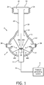
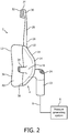
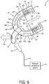
- FIGS. 1 and 2 are front and side elevational views, respectively, of a system 2 adapted to provide a regimen of respiratory therapy to a patient according to one exemplary embodiment.
- system 2 includes a respiratory mask 4, also referred to as a patient interface device, according to one exemplary embodiment that is shown schematically attached to a pressure generating system 6 via a user circuit 8, as is conventionally known in the art.
- Pressure generating system 6 is any device capable of generating a flow of breathing gas or providing gas at an elevated pressure.
- pressure generating systems include ventilators, constant pressure support devices (such as a continuous positive airway pressure device, or CPAP device) in which the pressure provided to the user is constant over the user's respiratory cycle, and variable pressure devices (e.g., BiPAP®, Bi-Flex®, or C-FlexTM devices manufactured and distributed by Philips Respironics of Murrysville, Pennsylvania) in which the pressure provided to the user varies with the user's respiratory cycle, and auto-titration pressure support devices.
- constant pressure support devices such as a continuous positive airway pressure device, or CPAP device
- variable pressure devices e.g., BiPAP®, Bi-Flex®, or C-FlexTM devices manufactured and distributed by Philips Respironics of Murrysville, Pennsylvania
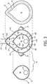
- FIG. 3 is an exploded view of respiratory mask 4.
- respiratory mask 4 includes a shell or frame assembly 10 and a cushion 12 attached to frame assembly 10 (frame assembly 10 and a cushion 12 may be collectively referred to as a flow delivery assembly/element).
- Frame assembly 10 includes a faceplate portion 11 having a segmented outer shell member 14 that receives and holds an inner shell member 16, each of which is described in greater detail elsewhere herein.
- User circuit 8 is coupled to ports 18 and 20 defined in outer shell member 14 and inner shell member 16, respectively, and, in the illustrated embodiment, includes an elbow connector 22 for that purpose.
- user circuit 8 is connected to frame assembly 10 so as to pivot or rotate relative to the frame assembly 10 and may or may not be detachable therefrom.
- any suitable coupling technique for joining user circuit 8 to frame assembly 10 is contemplated by the present invention.
- an exhaust vent 24 is provided in elbow connector 22 for exhausting a flow of gas from mask 4 to ambient atmosphere.
- Such exhaust vents are conventionally used in pressure support systems that use a single-limb, i.e., a single conduit, to communicate a flow of gas to an airway of a user.
- exhaust vent 24 can be any suitable exhaust vent, and can be located not only on elbow connector 22, but alternatively on another part of respiratory mask 4, such as on frame assembly 10.
- Respiratory mask 4 can have any one of a number of different configurations, shapes, and sizes.
- respiratory mask 4 is a nasal/oral mask structured to cover the nose and mouth of the patient.
- other types of respiratory masks such as, without limitation, a nasal mask, a nasal cushion or a full face mask, which facilitate the delivery of the flow of breathing gas to the airway of a patient, may be substituted for respiratory mask 4 while remaining within the scope of the present invention.
- Frame assembly 10 in the exemplary embodiment, is formed from a rigid or semi-rigid material, such as a polycarbonate or an injection molded thermoplastic.
- frame assembly 10 includes a forehead support 26.
- the forehead support is generally T-shaped and includes a support arm 28 which is coupled to a forehead support bracket 30.
- Forehead support bracket 30 includes a forehead pad 32 disposed on the user contacting side to engage the forehead of the user. It is to be understood that the present invention contemplates that forehead support 26, and its individual components, can have any one of a variety of alternative configurations. The present invention also contemplates that forehead support 26 can be eliminated entirely.
- a headgear attaches to respiratory mask 4 via headgear clips 34.
- Headgear clips 34 attach to straps (not shown) of the headgear, for example by inserting the straps into slots provided in headgear clips 34.
- headgear clips 34 are attached to each side of forehead support bracket 30 and to each side of the lower portion of frame assembly 10.
- Cushion 12 also referred to as a seal or sealing member, is, in the exemplary embodiment, a unitary structure made of a soft, flexible, cushiony, elastomeric material, such as, without limitation, silicone, an appropriately soft thermoplastic elastomer, a closed cell foam, or any combination of such materials.
- cushion 12 includes a first end portion 36 (defining an orifice) structured to sealingly engage the patient's face, a second end portion 38 (defining an orifice) opposite first end portion 36 that couples to the rear of frame assembly 10, and a sidewall 40 extending between first end portion 36 and second end portion 38 such that cushion 12 defines an inner chamber 41.
- faceplate portion 11 and cushion 12 are generally triangular-shaped and thus each include an apex region, a bottom region opposite the apex region, and first and second opposite side regions. It is to be understood that the present invention contemplates using any suitable technique for attaching second end portion 38 of cushion 12 to frame assembly 10. Such techniques may include permanently bonding cushion 12 to frame assembly 10, for example using adhesives or molding cushion 12 onto frame assembly 10, or attaching cushion 12 to frame assembly 10 using mechanical fasteners in a manner wherein cushion 12 is selectively detachable from frame assembly 10. When coupled to frame assembly 10, chamber 41 of cushion 12 receives the nose and mouth of the user when respiratory mask 4 is donned by the user so that the user's airway is in fluid communication with chamber 41.
- frame assembly 10 includes two parts, namely segmented outer shell member 14 and inner shell member 16.
- outer shell member 14 includes a central chamber 42 surrounded by a plurality of flow segments 44 each comprising a chamber having an inlet 46 at a first end thereof and one or more smaller orifices 48 at a second, opposite end thereof.
- outer shell member 14 includes five flow segments 44, labeled 44A-44E in the FIGS.
- flow segments 44A and 44B control flow over the left and right sides of the patient's nose, respectively, flow segments 44C and 44D control flow over the left and right cheeks of the patient, respectively, and flow segment 44E controls flow over the chin of the patient.
- inner shell member 16 defines a chamber 50 that extends from a first end 52 thereof to orifice 20.
- inner shell member 16 When respiratory mask 4 is assembled, inner shell member 16 is received and held within central chamber 42 of outer shell member 14 to form frame assembly 10.
- Inner shell member 16 may be held in place by any suitable means, such as an adhesive or a mechanical means such as a snap fit or friction fit.
- Cushion 12 is then attached to the back end of frame assembly 10.
- any suitable means such as an adhesive or a mechanical means such as a snap fit or friction fit.
- cushion 12 is attached to frame assembly 10 in a manner such that that outer edge of second end portion 38 of cushion 12 is aligned with the outer edge of outer shell member 14 and only partially covers the inlet 46 of each flow segment 44.
- gasses are able to flow from inner chamber 41 of cushion 12 into and through flow segments 44.
- respiratory mask 4 will now be described in connection with FIG. 4 .
- a flow of breathing gas represented by arrow 54
- the flow of breathing gas is generated from air in the environment surrounding pressure generating system 6
- a portion of the gas flow represented by arrow 56
- the remainder (non-leaked portion) of the gas flow will be delivered to inner chambers 50 and 41. That remaining flow will, as a result of the structure of respiratory mask 4 as described herein, provide two gas flow portions.
- a first gas flow portion will be the breathing gas that is delivered to the airway of the patient during the inspiratory phase of the patient (that flow is also present during the expiratory phase but the majority thereof is not delivered to the patient's airway and instead is opposed by the exhalation flow of the patient into chamber 50 and 41).
- a second gas flow portion represented by arrows 60, will, according to an aspect of the exemplary embodiment of the present invention, be caused to flow within respiratory mask 4. That flow will be a continuous flow of gas (on the order of several ml/min as compared to several l/min for the flow represented by arrow 58) that will flow from chamber 50 to chamber 41 and to the skin that is inside respiratory mask 4 but not directly covered/engaged by cushion 12. Thereafter, the continuous flow of gas will flow to flow segments 44 (and through the chambers) and out of frame assembly 10 through orifices 48 of flow segments 44.
- the flow represented by arrows 60 as just described will continuously flush the inner chambers 50 and 41 of respiratory mask 4 and as a result will minimize the CO 2 , heat and moisture effects of exhaled breaths inside respiratory mask 4 that are described elsewhere herein. Instead, the flow represented by arrows 60 will cause the inside of respiratory mask 4 to be filled with cooler, drier air from pressure generating system 6 (as noted elsewhere herein, that air is, in the exemplary embodiment, taken from the environment surrounding pressure generating system 6 and will thus generally have the same temperature and humidity as such air). As a result, the skin that is inside respiratory mask 4 but not directly covered/engaged by cushion 12 will receive the flow of gas represented by arrows 60 and be cooled.
- the flow of gas represented by arrows 60 is more than a negligible flow and is a predetermined percentage of an intentional (designed in) leak flow of respiratory mask 4 when the patient is not inhaling during use of respiratory mask 4, wherein the predetermined percentage is not more than a certain maximum percentage value.
- the flow of gas represented by arrows 60 when the patient is not inhaling, while more than a negligible flow is at most 10% of the intentional (designed in) leak flow (i.e., the certain maximum percentage value is 10%).
- the flow represented by arrows 60 when the patient is not inhaling is greater than or equal to 0.1% of the intentional (designed in) leak flow and less than or equal to 10% of the intentional (designed in) leak flow, while in another exemplary implementation the flow represented by arrows 60 when the patient is not inhaling is greater than or equal to 1% of the intentional (designed in) leak flow and less than or equal to 10% of the intentional (designed in) leak flow.
- the flow of gas represented by arrows 60 flows over at least one part of a user's face, the at least one part being chosen from the group of parts comprising: the nose bridge, the upper lip, the lower lip, the chin and/or the cheeks.
- the parts include the nose bridge, the upper lip and the cheeks. In another particular embodiment, the parts include the nose bridge, the upper lip, the lower lip, and the cheeks. In still another particular embodiment, the parts include all of the nose bridge, the upper lip, the lower lip, the chin and the cheeks.
- the higher CO 2 concentration gas, from the exhaled breath of the patient, will be flushed out of the mask by the flow of gas represented by arrows 60.
- at least 85% of any CO 2 present in the interior of the mask (from the last exhalation) will be flushed out of the mask by the flow of gas represented by arrows 60. This value is based on a calculation that assumes exhaled breath contains 4 % carbon dioxide, 500 ml of fresh air is inhaled for each breath, the dead volume of the mask is 100 ml and 1000 ppm CO 2 or less is not harmful for people. If the mask is flushed and at least 85% of all CO 2 in the mask from the last exhalation is removed, a safe level will be achieved.
- the corresponding flow depends on the breathing rate, the volume of inhaled air, the time between inhalation and exhalation and the actual dead volume of the mask filled with the patient nose and exhaled breath. Furthermore, as will be appreciated, the flow of gas represented by arrows 60 creates a gas flow away from the patient and minimizes the risk of direct and potentially uncomfortable gas flow directed toward the face of the patient.
- respiratory mask 4 is a nasal/oral mask structured to cover the nose and mouth of the patient. Furthermore, in the exemplary embodiment, the length of a first flow path within respiratory mask 4 along which the flow of gas represented by arrows 60 flows in order to the reach the user's face will be at least a certain first minimum value, wherein that first flow path is defined as the shortest pathway measured from the axis of the inflow port of shell member 16 to which elbow connector 22 is attached and alongside shell member 16 and cushion 12 to the face of the user.
- the length of a second flow path within respiratory mask 4 along which the flow of gas represented by arrows 60 flows from the user's face to an orifice 48 will be at least a certain second minimum value, wherein that flow path is defined as the shortest pathway measured from the face of the user alongside cushion 12 and shell member 16 to an orifice 48.
- the length of the first flow path will be at least 4 cm (4-6 cm in one embodiment) and the length of the second flow path will be at least 4 cm (4-6 cm in one embodiment) such that the total of the first and second flow paths will be at least 8 cm (8-12 cm in one embodiment).
- the value for the first and second flow paths just described would also apply to a full/total face mask type patient interface device.
- the length of the first flow path in the exemplary embodiment will be 1.5-3 cm (2 cm in one particular embodiment) and the length of the second flow path in the exemplary embodiment will be 1.5-3 cm (2 cm in one particular embodiment) such that the total of the first and second flow paths in the exemplary embodiment will be 3-6 cm (4 cm in one particular embodiment).
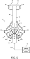
- FIG. 5 is a front elevational view of a system 2' adapted to provide a regimen of respiratory therapy to a patient according to an alternative exemplary embodiment.
- System 2' includes many of the same components as system 2 described above, and like components are labeled with like reference numerals.
- system 2' includes alternative respiratory mask 4' having a plurality of cover members 62 that may be selectively and sealingly attached to faceplate portion 11 over orifices 48.
- Cover members 62 may be attached to faceplate portion 11 using, for example, and without limitation, an adhesive (e.g., an adhesive rim provided around the cover member 62), or Velcro.
- cover members 62 are made of foam (see below) or another compressible material
- cover members 62 may be attached to faceplate portion 11 by compressing the cover member 62 and inserting the cover member 62 into a small pocket formed in faceplate portion 11. Once inserted, the foam cover member 62 will expand and fill the pocket creating a stable configuration.
- at least six cover members 62A-62E are provided for selectively covering orifices 48A-48E. Cover members 62 enable a patient to selectively control the nature/degree of the flow of gas through segmented outer shell member 14 by selectively controlling the rate of flow through each of the flow segments 44 by controlling the resistance to flow at orifices 48.
- cover members 62 may be made of a porous material, such as a fabric, foam, sponge, perforated foils, hairy materials like fur, high pile carpet or moleskin, or silicone rubber having a number of holes provided therein, which enables a certain degree of restricted gas flow through the associated orifice 48.
- cover members 62 may be made of a non-porous material, such as silicone rubber (or another silicone material), natural rubber, man-made rubber, cork, or an elastomer material, to prevent gas flow through the associated orifice 48 and thus completely restrict flow through the associated flow segment 44.
- one or more porous cover members 62 e.g., having different degrees of porosity
- a non-porous cover member 62 are provided for each orifice such that the patient may, for each orifice 48, choose to leave it open/uncovered, choose to cover it with a porous cover member 62 so as to restrict flow to a certain degree (depending on the porosity of the material used to make the cover member 62), or choose to cover it with a non-porous cover member 62 so as to completely restrict flow.
- the patient is able to selectively design the flow through respiratory mask 4' to suit his or her particular likes and needs.
- FIG. 6 is a schematic diagram in partial cross-section of a system 2" adapted to provide a regimen of respiratory therapy to a patient according to a further alternative exemplary embodiment.
- System 2 includes many of the same components as systems 2 and 2' described above, and like components are labeled with like reference numerals.
- an alternative respiratory mask 4" is provided in system 2".
- respiratory mask 4" includes an inner shell member 16" having an extension member 64 extending from the first end 52 of inner shell member 16" into inner chamber 41 of cushion 12.
- extension member 64 follows the contours of respiratory mask 4", and in particular the outer contours of cushion 12.
- entry channel 66 is formed between the distal end of extension member 64 first end portion 36 of cushion 12.
- the configuration of this embodiment will produce a flow represented by arrows 60". As seen in FIG. 6 , that flow will contact more of the inner surface of cushion 12, and in particular, more of sidewall 40 of cushion 12, as compared to flow 60 shown in FIG. 4 .
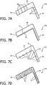
- FIG. 7A is a schematic representation of a portion of a cushion 12A that may be employed in respiratory mask 4, respiratory mask 4', or respiratory mask 4" in an exemplary embodiment.
- cushion 12A is perforated with a number of small channels 68 that extend through the walls of cushion 12A.
- channels 68 are small enough to minimize the potential for discomfort to the patient that may result from gas flowing through channels 68 and directly onto the skin.
- the diameter of channels 68 is between 0.1 mm and 5 mm, and in another particular embodiment, the diameter of channels 68 is between 0.1 mm and 1 mm. Also, in the exemplary embodiment, the size and number of channels 68 is controlled so as to avoid making cushion 12A too flexible (i.e., potentially unstable). The optimal size and number of channels 68 will be determined by each particular application, and can lead appropriately flexible/stable and cool mask.
- FIG. 7B is a schematic representation of a portion of a cushion 12B that may be employed in respiratory mask 4, respiratory mask 4', or respiratory mask 4" in an exemplary embodiment.
- cushion 12B includes a layer 70 of material having a high specific heat conductivity that is provided on the inner surface 72 of cushion 12B.
- layer 70 is a relatively thin layer of material, having a thickness of 20 nm - 1 mm in one particular embodiment, or, alternatively, 20 nm - 100 nm in another particular embodiment.
- Layer 70 will provide a substantially uniform temperature along inner surface 72 (by helping to spread the heat flow) and improve the heat exchange between the flow of gas within inner chamber 41 and cushion 12.
- the material of layer 70 has a thermal conductivity of 50 W /mK or more.
- layer 70 is made of a thin film/foil of material (e.g., metal), such as, without limitation, aluminum, Au, Cu , Ag, W, amorphous diamond, graphite, aluminum nitride, boron nitride, or graphene.
- FIG. 7C is a schematic representation of a portion of a cushion 12C that may be employed in respiratory mask 4, respiratory mask 4', or respiratory mask 4" in an exemplary embodiment.
- cushion 12C includes a varying surface texture that is provided on the inner surface 72 of cushion 12C.
- the varying surface texture is provided by a plurality of dimples or indentations 74 that are provided in inner surface 72.
- dimples 74 are generally partially spherical in shape and have a diameter of between 0.1 and 5 mm.
- the varying surface texture of this embodiment will cause a turbulent gas flow over inner surface 72, which is a more efficient type of flow for facilitating heat exchange.
- FIG. 7D is a schematic representation of a portion of a cushion 12D that may be employed in respiratory mask 4, respiratory mask 4', or respiratory mask 4" in an exemplary embodiment.
- cushion 12D includes a plurality of heat conductive particles or fibers 76 which are provided (e.g., randomly or uniformly) within the body of cushion 12D during the manufacturing thereof (e.g., a molding process) in order to increase the heat conductivity of cushion 12D so as to increase the heat flow from the patient's skin to the heat exchange area within inner chamber 41 of cushion 2.
- Heat conductive particles or fibers 76 may be, for example and without limitation, aluminum, tungsten, gold, copper, silver, aluminum nitride, aluminum oxide, zinc oxide, boron nitride, or carbon black particles or fibers.
- the optimal type and number of particles or fibers 76 will be determined by each particular application, with care being taken to not unduly increase the stiffness of cushion 12.
- each of the particles or fibers 76 is connected to and forms a bridge (i.e., is directly or indirectly connected to) to an outside edge of cushion 12D, such as being connected to one or more other particles or fibers (i.e., the particles or fibers 76 do not all need to be connected to one another, rather at least some need to be connected and form pathways for the heat transport to an outside edge of cushion 12D; generally, the more the better, but the more that are used, the stiffer the cushion 12 will become, and care should be taken to not unduly increase the stiffness).
- a plurality of lines of such heat conductive materials may be provided within cushion 12 extending from inner surface 72 to the outside/outer surface of cushion 12.
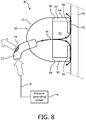
- FIG. 8 is a schematic diagram in partial cross-section of a system 80 adapted to provide a regimen of respiratory therapy to a patient according to a comparative example
- System 80 includes many of the same components as system 2 described elsewhere herein, and like components are labeled with like reference numerals.
- an alternative respiratory mask 82 is provided in system 80.
- respiratory mask 82 includes a shell member 16 as described elsewhere herein having an alternative cushion 84 attached thereto (in the example, cushion 84 may be made from any of the same materials as cushion 12 described elsewhere herein).
- Cushion 84 includes an end portion 86 (defining an orifice) structured to engage the skin 87 of the patient's face (in the example, end portion 86 is structured to sealingly engage the skin 87), an end portion 88 (defining an orifice for receiving gas flow into the cushion) opposite end portion 86 that couples to the rear of shell member 16, and a sidewall 90 extending between end portion 86 and end portion 88 such that cushion 12 defines an inner chamber 91.
- Shell member 16 and cushion 84, or cushion 84 alone, may be referred to as a flow delivery assembly/element.
- End portion 86 includes a contacting portion 92 that comprises a textured surface structured to contact the skin of the user.
- contacting portion 92 covers the entire exposed surface of end portion 86. In an alternative example, contacting portion 92 covers only selected, well defined areas of end portion 86.
- the textured surface is a random surface having a plurality of surface features, such as, for example and without limitation, bumps, dimples, pillars, domes, valleys, ridges, undulations and serrations.
- the textured surface is an engineered surface.
- engineered surface shall mean a designed surface texture having a plurality of one or more types of surface features wherein for each type of surface feature the surface feature has a non-random, predefined/predesigned geometry and/or non-random, predefined/predesigned dimensions and/or interrelationships among one another.
- the surface features that may form part of an engineered surface include, for example and without limitation, bumps, dimples, pillars, domes, valleys, ridges, undulations and serrations. These surface features minimize the real area of contact with the skin, thereby providing low friction (compared to a nominally flat surface).
- the surface features that may form part of an engineered surface are "non-connected surface features".
- the term "non-connected surface feature” shall mean a surface feature that extends upwardly from a surface and that is not connected to any adjacent surface features at a point located above the surface from which the surface feature extends by, for example, a ridge or similar connecting structure. Examples of such "non-connected surface features" are the pillars shown in FIGS. 9C and 9D and described below.
- the textured surface of contacting portion 92 provides well defined gaps between cushion 84 and skin 87.
- a small continuous gas flow as indicated by arrows 94 will be created within and through cushion 84.
- that gas flow will flow over skin 87 and out of respiratory mask 82 through the gaps.
- the gas flow just described will be in direct contact with skin 87 and as a result will effectively cool skin 87, remove moisture from skin 87, and flush CO 2 from inner chamber 91.
- the flow of gas represented by arrows 94 is more than a negligible flow and is a predetermined percentage of an intentional (designed in) leak flow of respiratory mask 82 when the patient is not inhaling during use of respiratory mask 82, wherein the predetermined percentage is not more than a certain maximum percentage value.
- the flow of gas represented by arrows 94 when the patient is not inhaling, while more than a negligible flow is at most 10% of the intentional (designed in) leak flow (i.e., the certain maximum percentage value is 10%).
- the flow represented by arrows 94 when the patient is not inhaling is greater than or equal to 0.1% of the intentional (designed in) leak flow and less than or equal to 10% of the intentional (designed in) leak flow, while in another exemplary implementation the flow represented by arrows 94 when the patient is not inhaling is greater than or equal to 1% of the intentional (designed in) leak flow and less than or equal to 10% of the intentional (designed in) leak flow.
- at least 85% of any CO 2 present in the interior of the mask 82 (from the last exhalation) will be flushed out of the mask by the flow of gas). Respiratory mask 82 will leak, but the leakage is small and the required patient pressure will still be achieved.
- the flow of gas represented by arrows 94 flows over at least one part of a user's face, the at least one part being chosen from the group of parts comprising: the nose bridge, the upper lip, the lower lip, the chin and/or the cheeks.
- the parts include the nose bridge, the upper lip and the cheeks.
- the parts include the nose bridge, the upper lip, the lower lip, and the cheeks.
- the parts include all of the nose bridge, the upper lip, the lower lip, the chin and the cheeks.
- respiratory mask 82 is a nasal/oral mask structured to cover the nose and mouth of the patient.
- the length of the flow path within respiratory mask 82 along which the flow of gas represented by arrows 94 flows in order to the reach the user's face will be at least a certain minimum value, wherein that flow path is defined as the shortest pathway measured from the axis of the inflow port of shell member 16 to which elbow connector 22 is attached and alongside shell member 16 and cushion 90 to the face of the user (which engages the inner edge of contacting portion 92).
- the length of the flow path will be at least 4 cm 4-6 cm in one particular example).
- the value for the flow path just described would also apply to a full/total face mask type patient interface device.
- respiratory mask 82 was adapted to be a nasal mask structured to cover the nose of the patient, the length of the flow path in the example will be 1.5-3 cm (2 cm in one particular example).
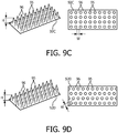
- FIG. 9A is a schematic representation of contacting portion 92A according to one example.
- contacting portion 92A comprises an engineered surface having a plurality of dome/pillar (smooth) shaped surface features, each labeled with reference numeral 95, which provide a plurality of gaps, each labeled with reference numeral 96.
- Each gap 96 is defined by a height H and width W.
- the term “height” shall mean the vertical distance between the highest point of the tallest surface feature 95 immediately adjacent the gap 96 and the lowest surface of contacting portion 92 on which the surface features 95 sits
- the term “width” (also commonly called “pitch”) shall mean the largest of the distances between highest points of adjacent surface features 95 which define the gap.
- the gaps 96 have equal heights H and widths W (as used herein, when comparing height and width values of gaps within a textured surface, "equal” shall mean the values are all within a 10% or less manufacturing tolerance of one another).
- FIGS 9B-9D are schematic representations of contacting portions 92B-92D according to alternative examples. As seen in FIG. 9B-9D , contacting portion 92B comprises an engineered surface where the surface features 95 have a rectangular cross-section, and contacting portions 92C and 92D comprise engineered surfaces with different, alternative dome/pillar shaped surface features 95.
- the capacity of gas flow 94 to cool skin 87 depends on the flow rate, the heat exchange efficiency, and the temperature and humidity of the gas (which, as described elsewhere herein, is in the example generated from the air in the environment surrounding system 80).
- the flow rate in the gaps e.g., gaps 96 in FIGS. 9A-9D
- the system pressure e.g., CPAP pressure
- the system pressure is set by the physician and cannot be changed.
- the only factor that may be easily controlled is the flow resistance.
- the flow resistance can be controlled by controlling the effective gap height H and/or the effective gap width W (i.e., pitch within the gap).
- the effective height of the gaps is a combination of the surface roughness of skin 87 and the roughness or texture of cushion 84. If the effective gap is too small, not enough gas (e.g., air) will flow through the gap and skin 87 will not be cooled enough. If the gaps are too large, too much gas will flow, skin 87 will become too cold and the flow will make noise that can be a nuisance for the patient. Furthermore, the heat exchange efficiency will be lower with larger gaps as only a small part of the flow will interact with skin 87.
- gas e.g., air
- the present inventors have determined that, in one example, effective cooling can be provided by providing a textured surface on contacting portion 92 wherein the height of the gaps formed therein are 100 microns to 1000 microns, and, in another alternative example, 100 microns to 200 microns, and wherein the width/pitch of the gaps are, in one embodiment, 10 microns to 1000 microns, and in another embodiment 100 microns to 1000 microns.
- the present inventors have also determined that, in one particular example, optimal cooling efficiency can be provided by providing a textured surface on contacting portion 92 wherein the height of the gaps formed therein are 100 microns to 150 microns.
- the examples just described may be implemented in an engineered surface wherein the heights H of the gaps are equal and are greater than 100 microns and less than or equal to 1000 microns, greater than 100 microns and less than or equal to 200 microns, or greater than 100 microns and less than or equal to 150 microns.
- the examples just described may also be implemented in a random textured surface wherein the heights H of the gaps, while not equal, are greater than 100 microns and less than or equal to 1000 microns, greater 100 microns and less than or equal to 200 microns, or greater than 100 microns and less than or equal to 150 microns.
- the gaps described herein are provided such that a controlled flow of air is created in the order of 3 g/s per cm or more in the direction of the seal that cools the skin.
- the "effective height" of the gaps is a combination of the surface roughness of skin 87 and the roughness or texture of cushion 84.
- a cushion may be custom designed for a patient wherein the surface roughness of skin 87 of the patient is taken into account.
- an engineered surface may be designed for a cushion 84 wherein the heights H of the gaps are chosen such that the "effective gap height" of each gap when worn by the patient will be greater than 100 microns and less than or equal to 200 microns or, alternatively, greater than 100 microns and less than or equal to 150 microns.
- the patient is able to control the humidity of the flow of gas that is generated thereby. It should be noted that the higher the humidity of the generated gas flow, the less effective the cooling will be.
- FIG. 10 is a schematic diagram m partial cross-section of a system 100 adapted to provide a regimen of respiratory therapy to a patient according to another alternative comparative example.
- System 100 includes many of the same components as systems 2 and 80 described elsewhere herein, and like components are labeled with like reference numerals.
- alternative respiratory mask 102 includes a liner 104 (made of the same or a similar materials as cushion 12) that is attached (e.g., by any suitable method such as using an adhesive or molding) to end portion 36 of cushion 12.
- liner 104 includes a contacting portion 92 having a textured surface as described elsewhere herein in connection with FIGS. 8-9D .
- alternative respiratory mask 102 is able to provide the same or similar continuous flow and the same or similar cooling effect as described in connection with respiratory mask 82 (see arrows 94).
- Shell member 16, cushion 12 and liner 104, or cushion 12 and liner 104 alone, may be referred to as a flow delivery assembly/element.
- FIG. 11 is a schematic diagram in partial cross-section of a system 110 adapted to provide a regimen of respiratory therapy to a patient according to still another alternative comparative example.
- System 110 includes many of the same components as systems 2, 80 and 100 described elsewhere herein, and like components are labeled with like reference numerals.
- alternative respiratory mask 112 includes a spacer/liner 114 that is attached (e.g., by any suitable method such as using an adhesive or molding) to first end portion 36 of cushion 12. Alternatively, spacer/liner 114 may simply rest between cushion 12 and skin 87 without being attached to cushion 12, in which case it will be held in place by the strapping forces of respiratory mask 112.
- spacer/liner liner 114 is made of a porous material that allows a certain degree of fluid flow therethrough, as indicated by arrows 116 in FIG. 11 .
- Liner 114 may be made of, for example and without limitation, a textile material, foam, a sponge material, fur, moleskin, high pile carpet materials.
- textile shall mean a material consisting of a network of interlaced natural or artificial fibers made by, for example and without limitation, weaving, knitting, spreading, crocheting, or bonding the fibers to form the network.
- alternative respiratory mask 112 is able to provide a continuous gas flow and a cooling effect that is similar to that described in connection with respiratory masks 82 and 102 elsewhere herein (see arrows 116 in FIG. 11 ).
- spacer/liner 114 provides a gap for allowing fluid flow in between cushion 12 and skin 87.
- the gap spacer/liner 114 is structured such that a controlled flow of air is created in the order of 3 g/s per cm or more in the direction of the seal that cools the skin.
- Shell member 16, cushion 12 and liner 114, or cushion 12 and liner 114 alone, may be referred to as a flow delivery assembly/element.
- the capacity of a gas flow through cushion 12 to cool skin 87 depends on the flow rate, the heat exchange efficiency, and the temperature and humidity of the gas (which, as described elsewhere herein, is in the example generated from the air in the environment surrounding system 110).
- the flow rate through spacer/liner 114 is governed by the system pressure (e.g., CPAP pressure) and the flow resistance.
- the system pressure is set by the physician and cannot be changed.
- the only factor that may be easily controlled is the flow resistance.
- the flow resistance can be controlled/determined by the porosity of the material used to construct spacer/liner 114.
- porosity is a measure of the void (i.e., "empty") spaces in a material, and is a fraction/ratio of the volume of voids ("void volume") in the material over the total/bulk volume of the material, between 0-1, or as a percentage between 0-100%.
- weight per cubic meter is calculated by dividing weight per square meter by thickness. The specific weight of a material fabric gives the occupied volume of the solid fabric and this is recalculated to the ratio of void volume (without fabrics) to the total bulk volume.
- the present inventors have found that effective cooling can be provided by constructing spacer/liner 114 of a material having a porosity of 80% - 94%.
- the porosity is 80% - 90%, with one particular implementation being 88%.
- the material for constructing spacer/liner 114 may be specified/chosen based on characteristics of the material relating to flow through the material.
- respiratory masks have a certain level of designed in intentional leak.
- the present inventors have found that effective cooling can be provided by constructing spacer/liner 114 of a material having a certain leakage flow through the fabric expressed as a % of the intentional leak flow of the associated mask.
- the leakage flow through the fabric is 0-50 % of the intentional leak flow
- the leakage flow through the fabric is 0-10% of the intentional leak flow
- the leakage flow through the fabric 0-5 % of the intentional leak flow.
- the fabric may have a leakage flow of 1.4 SLPM (5%).
- the fabric of the spacer/liner 114 may be specified based simply on a value for the flow through the fabric at a certain pressure. In one example, that flow at 10 cmH2O is 0-50 SLPM (or 5-50 SLPM), and in another embodiment, that flow at 10 cmH2O is 0-5 SLPM.
- the fabric of the spacer/liner 114 may be specified based on the permeability of the fabric to air (with pressures ranging from 500 Pa to 2000 Pa).
- permeability is 0-15000 l/m 2 s
- permeability is 0-1500 l/(m 2 s)
- permeability is 0-750 l/(m 2 s).
- a mask configuration having an air permeability of 750 will yield a flow of around 4.5 liters/min through the fabric.
- spacer/liner 114 is made from polyester fabric and contains small flexible fibers, like pillars, which will bend under any shear stress of respiratory mask 112. Skin 87 will have minimal shear stress which will lead to reduce red marks, skin irritation and even pressure ulcers for the patient.
- spacer/liner 114 will be optimized to provide the most effective cooling. If spacer/liner 114 is too thick, e.g. 10 mm or more, and open, it will leak too much and even the required system (e.g., CPAP) pressure cannot be obtained. A thicker material will also have the disadvantage that a large part of the gas flow will not interact with skin 87. The heat exchange is also not efficient in this case. If spacer/liner 114 is too thin, not enough gas will flow and skin 87 will be not cooled. Furthermore, the stiffness of spacer/liner 114 is important since respiratory mask 112 is pressed onto the patient's face.
- spacer/liner 114 is too soft, it will be pressed together and the effective gap becomes too small.
- the present inventors have found that a certain pressure applied to the skin by a mask will give red marks on the skin. In particular, the present inventors have found that the majority of people will get red marks form a mask with a pressure of 90 g. per square cm (9 kPa) or more.
- the stiffness of spacer/liner 114 is selected so that it will result in a gap of at least 0.1 mm and a porosity in the range of 80-90 % when a pressure is applied with a value of 10 kPa or lower.
- the present inventors have determined that, in one exemplary example, effective cooling will be provided by a spacer/liner 114 having a thickness between 0.1 mm and 8 mm, and in another, more particular example, between 0.5 mm and 3 mm. Furthermore, it is important to note that, in the example of FIG. 11 , the roughness of skin 87 has little influence on the degree of flow, and thus does not affect cooling greatly. As a result, the example of FIG. 11 may be employed to provide effective cooling with a wide variety of patients with varying degrees of skin roughness.
- respiratory mask 112 is a nasal/oral mask structured to cover the nose and mouth of the patient.
- the length of the flow path within respiratory mask 112 along which the flow of gas represented by arrows 94 flows in order to the reach the user's face will be at least a certain minimum value, wherein that flow path is defined as the shortest pathway measured from the axis of the inflow port of shell member 16 to which elbow connector 22 is attached and alongside shell member 16 and cushion 12 to the face of the user (which engages the inner edge of spacer/liner 114).
- the length of the flow path will be at least 4 cm (4-6 cm in one particular example).
- the value for the flow path just described would also apply to a full/total face mask type patient interface device.
- respiratory mask 82 was adapted to be a nasal mask structured to cover the nose of the patient, the length of the flow path in the exemplary embodiment will be 1.5-3 cm (2 cm in one particular example).
- shell member 16 may be omitted, and elbow connector 22 may instead be attached directly to the orifice defined at the end portion 38, 88 of the cushion for receiving gas flow into the cushion.
- FIG. 12 is a front elevational view of spacer/liner 114 according to one non-limiting example. Eyes are very sensitive to any air flow and people will tend to wake up if they feel a small air flow in their eyes. Therefore, in the example of FIG. 12 , air flow is controlled to make sure that only the most sensitive areas of the patient are cooled and that there is minimal to no flow into the eyes of the patient.
- Spacer/liner 114 in this example includes a porous portion 116 (made of a porous material as described elsewhere herein) and a non-porous sealing portion 118. Sealing portion 118 is made of a material such as, without limitation, silicone, liquid silicone rubber, other skin compatible resins, low porous foam, or densely woven fabrics. As seen in FIG.
- sealing portion 118 extends from the middle of the first side 120 of spacer/liner 114, over the apex 122 of spacer/liner 114 and to the second side 124 of spacer/liner 114. Sealing portion 118 also extends over the full depth of spacer/liner 114. As a result, the sides of spacer/liner 114 near the eyes of the patient are sealed by sealing portion 118, which sealing will minimize gas flow out in the direction of the eyes of the patient.
- spacer/liner 114 has a flow pattern structured to guide the flow alongside to nose to the bottom side of respiratory mask 112 such that the main part of the flow through spacer/liner 114 will exit spacer/liner 114 at the chin or mouth side of respiratory mask 112, depending on whether respiratory mask 112 is a nasal mask or a nasal/oral mask.
- the part of spacer/liner 114 that is shown as being covered by sealing portion 118 may instead be closed by another mechanism.
- that area of spacer/liner 114 may be filled up with a resin, rubber, or low porosity foam, or may be made of a highly densely woven fabric.
- the air flow in the enclosed area will be smaller than in the non enclosed area as it has to flow a longer way than in other non enclosed area of the patch.
- the textile can be woven that there is a lower flow resistance in the enclosed area than in the non enclosed area.
- the fabric will have a lower density in the enclosed area than in the non enclosed area or it will have a higher gap height. Therefore, the amount of air flow in the enclosed area is the same as in the non enclosed area.
- the flow rate is different in different parts of spacer/liner 114 to optimize the comfort. This is accomplished by controlled the density or openness of the material of spacer/liner 114. In particular, flow rate is smaller near the bottom side of respiratory mask 112, as indicated by the thicker and thinner arrows. The difference in flow rate will generate areas with a different temperature, such that spacer/liner 114 will have a decreasing temperature gradient extending from top to bottom.
- flow rate is controlled by controlling the height and/or pitch of the surface feature as described herein.
- smaller pitch (more features per square mm) and/or smaller height may be used at the top of the surface (over the nose), and larger pitch (less features per square mm) and/or smaller height, or a random roughness with a higher Ra value (higher roughness) may be used at the bottom, of the surface (near the mouth).
- a textured surface may designed so as to have a decreasing temperature gradient extending from top to bottom.
- any reference signs placed between parentheses shall not be construed as limiting the claim.
- the word “comprising” or “including” does not exclude the presence of elements or steps other than those listed in a claim.
- several of these means may be embodied by one and the same item of hardware.
- the word “a” or “an” preceding an element does not exclude the presence of a plurality of such elements.
- any device claim enumerating several means several of these means may be embodied by one and the same item of hardware.
- the mere fact that certain elements are recited in mutually different dependent claims does not indicate that these elements cannot be used in combination.
Landscapes
- Health & Medical Sciences (AREA)
- Veterinary Medicine (AREA)
- Engineering & Computer Science (AREA)
- General Health & Medical Sciences (AREA)
- Public Health (AREA)
- Biomedical Technology (AREA)
- Heart & Thoracic Surgery (AREA)
- Animal Behavior & Ethology (AREA)
- Life Sciences & Earth Sciences (AREA)
- Pulmonology (AREA)
- Anesthesiology (AREA)
- Emergency Medicine (AREA)
- Hematology (AREA)
- Physics & Mathematics (AREA)
- Thermal Sciences (AREA)
- Vascular Medicine (AREA)
- Respiratory Apparatuses And Protective Means (AREA)
- Measurement Of The Respiration, Hearing Ability, Form, And Blood Characteristics Of Living Organisms (AREA)
- Thermotherapy And Cooling Therapy Devices (AREA)
Claims (8)
- Benutzerschnittstellenelement zur Abgabe eines Atemgases an einen Benutzer, umfassend:- eine erste Öffnung (18) zum Empfangen einer ersten Gasströmung, und eine oder mehrere zweite Öffnungen (48) zum Austreten lassen einer zweiten Gasströmung aus dem Benutzerschnittstellenelement, wobei die erste Öffnung und die eine oder mehrere zweite Öffnungen derartig in Bezug zueinander angeordnet sind, dass die zweite Gasströmung während der Verwendung des Benutzerschnittstellenelements über eine Hautoberfläche des Benutzers strömt und diese kühlt und durch die eine oder mehrere zweite Öffnungen aus dem Benutzerschnittstellenelement austritt,wobei das Benutzerschnittstellenelement eine Schaleneinheit (14) umfasst, die konstruiert ist, um ein Polster (12) aufzunehmen, wobei die erste Öffnung und die eine oder mehrere zweite Öffnungen in der Schaleneinheit vorgesehen sind,
wobei die Schaleneinheit eine Vielzahl von Strömungssegmenten (44) umfasst, wobei jedes der Strömungssegmente eine Kammer mit einem Einlass (46) an einem ersten Ende der Schaleneinheit und eine oder mehrere offene Öffnungen (48) in einem Abstand von dem Einlass an einem zweiten, dem ersten Ende gegenüberliegenden Ende der Schaleneinheit umfasst, wobei jede der einen oder mehreren offenen Öffnungen eine von den zweiten Öffnungen sind, wobei das erste Ende der Schaleneinheit konstruiert ist, um derartig mit dem Polster gekoppelt zu werden, dass eine innere Kammer (41) des Polsters in Fluidkommunikationsverbindung mit jedem der Strömungssegmente steht, und wobei das Benutzerschnittstellenelement konstruiert ist, um in Reaktion darauf, dass eine erste Gasströmung durch die erste Öffnung empfangen wird, dafür zu sorgen, dass mindestens ein Teil der zweiten Gasströmung durch jedes der Strömungssegmente vom Einlass des Strömungssegments zu der einen oder mehreren offenen Öffnungen des Strömungssegments strömt, dadurch gekennzeichnet, dass die eine oder mehrere offene Öffnungen kleiner als der Einlass sind. - Benutzerschnittstellenelement nach Anspruch 1, wobei das eine oder mehrere Strömungssegmente (44) eine Vielzahl von Strömungssegmenten (44) sind, wobei die Vielzahl von Strömungssegmenten erste und zweite Strömungssegmente (44A, 44B) in einem ersten Abschnitt der Schaleneinheit (14) umfassen, die konstruiert sind, um die Strömung über die Seiten der Benutzernase zu lenken, und dritte und vierte Strömungssegmente (44C, 44D) an gegenüberliegenden Seiten eines zweiten Abschnitts der Schaleneinheit umfassen, die konstruiert sind, um die Strömung über die Wangen des Benutzers zu lenken, und ein fünftes Strömungssegment (44E) in einem dritten Abschnitt der Schaleneinheit umfassen, das konstruiert ist, um die Strömung über das Kinn des Benutzers zu lenken.
- Benutzerschnittstellenelement nach Anspruch 1, wobei das eine oder mehrere Strömungssegmente (44) eine Vielzahl von Strömungssegmenten (44) sind, wobei die Schaleneinheit eine zentrale Kammer (42) umfasst, die durch die Vielzahl von Strömungssegmenten umgeben ist, und wobei das Benutzerschnittstellenelement weiterhin eine innere Schaleneinheit (16) umfasst, die in der zentralen Kammer aufgenommen ist, wobei die innere Schaleneinheit eine zweite innere Kammer (50) definiert, die konstruiert ist, um in Fluidkommunikationsverbindung mit der inneren Kammer (41) des Polsters (12) zu stehen, wenn die Schaleneinheit mit dem Polster gekoppelt ist, wobei die zweite innere Kammer konstruiert ist, um die Atemgasströmung zu empfangen und die Atemgasströmung an die innere Kammer des Polsters abzugeben.
- Benutzerschnittstellenelement nach Anspruch 1, wobei das eine oder mehrere Strömungssegmente (44) eine Vielzahl von Strömungssegmenten (44) sind, weiterhin umfassend eine Vielzahl von Abdeckungseinheiten (62), wobei jede der Abdeckungseinheiten konstruiert ist, um selektiv an der Schaleneinheit (14) über einer ausgewählten der offenen Öffnungen (48) angebracht zu werden, wobei jede der Abdeckungseinheiten entweder aus einem porösen Material besteht, das eine begrenzte Gasströmung durch das Material erlaubt, oder aus einem nicht-porösen Material besteht, das eine Gasströmung durch das Material verhindert.
- Benutzerschnittstellenelement nach Anspruch 1, weiterhin umfassend eine Verlängerungseinheit (64), die sich vom ersten Ende der Schale in die innere Kammer (41) des Polsters (12) hinein erstreckt, wobei die Verlängerungseinheit vorgesehen ist, um einen Eintrittskanal (66) zwischen einem distalen Ende der Verlängerungseinheit und einem ersten Endabschnitt des Polsters zu definieren, wenn die Schaleneinheit mit dem Polster gekoppelt ist.
- Benutzerschnittstellenelement nach Anspruch 1, wobei die Schaleneinheit (14) mit dem Polster (12) gekoppelt ist,
wobei mindestens entweder: (i) das Polster mit einer Anzahl von Kanälen (68) perforiert ist, die sich durch eine oder mehrere Wände des Polsters erstrecken, oder (ii) eine Schicht (70) aus Material mit einer Wärmeleitfähigkeit von 50 W/mK oder mehr auf einer Innenfläche (72) des Polsters vorgesehen ist, wobei die Schicht konstruiert ist, um für eine im Wesentlichen gleichmäßige Temperatur entlang der Innenfläche zu sorgen, wobei die Schicht mindestens entweder (a) ein dünner Film aus Material mit einer Dicke von 20 nm bis 100 nm ist oder (b) aus Aluminium, Au, Cu, Ag, W, amorphem Diamant, Grafit, Aluminiumnitrid, Bornitrid oder Graphen besteht, oder (iii) zahlreiche Eindellungen (74) auf einer Innenfläche (72) des Polsters vorgesehen sind, um eine variierende Oberflächentextur zu bilden, so dass die variierende Oberflächentextur konstruiert ist, um eine turbulente Gasströmung über die Innenfläche zu verursachen, oder (iv) eine Vielzahl von wärmeleitenden Faserpartikeln (76) in einem Körper des Polsters vorgesehen sind. - Benutzerschnittstellenelement nach Anspruch 1, wobei das Benutzerschnittstellenelement die Schaleneinheit (14) ist, die konstruiert ist, um mit einem Polster (12) gekoppelt zu werden, wobei die erste Öffnung (18) und die eine oder mehrere zweite Öffnungen (48) in der Schaleneinheit vorgesehen sind, wobei die erste Gasströmung bei der ersten Öffnung in die Schaleneinheit eintritt und die zweite Gasströmung bei der einen oder mehreren zweiten Öffnungen aus der Schaleneinheit austritt.
- Benutzerschnittstellenvorrichtung (4, 4', 4") umfassend das Benutzerschnittstellenelement nach einem der vorhergehenden Ansprüche.
Applications Claiming Priority (2)
| Application Number | Priority Date | Filing Date | Title |
|---|---|---|---|
| US201261616024P | 2012-03-27 | 2012-03-27 | |
| PCT/IB2013/051858 WO2013144753A1 (en) | 2012-03-27 | 2013-03-08 | User interface device providing for improved cooling of the skin |
Publications (2)
| Publication Number | Publication Date |
|---|---|
| EP2830690A1 EP2830690A1 (de) | 2015-02-04 |
| EP2830690B1 true EP2830690B1 (de) | 2017-08-02 |
Family
ID=48184265
Family Applications (1)
| Application Number | Title | Priority Date | Filing Date |
|---|---|---|---|
| EP13718647.4A Not-in-force EP2830690B1 (de) | 2012-03-27 | 2013-03-08 | Benutzerschnittstellenvorrichtung zur verbesserten kühlung der haut |
Country Status (6)
| Country | Link |
|---|---|
| US (1) | US10028859B2 (de) |
| EP (1) | EP2830690B1 (de) |
| JP (1) | JP6357144B2 (de) |
| CN (1) | CN104203324B (de) |
| RU (1) | RU2647153C2 (de) |
| WO (1) | WO2013144753A1 (de) |
Families Citing this family (21)
| Publication number | Priority date | Publication date | Assignee | Title |
|---|---|---|---|---|
| US10688266B2 (en) * | 2013-01-18 | 2020-06-23 | ResMed Pty Ltd | Patient interface and method for making same |
| CA3176976A1 (en) | 2014-05-09 | 2015-11-12 | Fisher & Paykel Healthcare Limited | Customizable respiratory mask |
| US10159813B2 (en) | 2014-05-21 | 2018-12-25 | Atom Medical Corporation | Gas supply mask apparatus |
| JP6271346B2 (ja) * | 2014-06-12 | 2018-01-31 | アトムメディカル株式会社 | ガス類供給用マスク装置 |
| EP2957314B1 (de) * | 2014-06-17 | 2018-03-21 | ResMed Ltd. | Dichtungsbildungsabschnitt, Kissen und Polster für eine Patientenschnittstelle |
| WO2016030381A1 (en) * | 2014-08-28 | 2016-03-03 | Koninklijke Philips N.V. | Cpap pressurized gas permeable mask cushion |
| JP2016052489A (ja) * | 2014-09-04 | 2016-04-14 | 高橋 勲 | Cpapマスクの違和感軽減手段 |
| JP7091401B2 (ja) * | 2014-09-18 | 2022-06-27 | レスメド・プロプライエタリー・リミテッド | 患者インタフェースのためのガス洗浄ベント |
| WO2016041019A1 (en) * | 2014-09-18 | 2016-03-24 | Resmed Limited | Gas washout vent for patient interface |
| JP6991125B2 (ja) | 2015-07-20 | 2022-01-12 | レスメド・プロプライエタリー・リミテッド | 減容部材を備えた患者インターフェース |
| EP3922890B1 (de) | 2015-09-23 | 2023-11-29 | ResMed Pty Ltd | Entlüftungsadapter für ein atemtherapiesystem |
| EP3463537B1 (de) * | 2016-06-03 | 2020-10-21 | Koninklijke Philips N.V. | Dämpfungselement und herstellungsverfahren dafür |
| US10507298B2 (en) * | 2017-07-05 | 2019-12-17 | Orel Yehuda SWENSON | Respiration mask and seal therefor |
| JP7145939B2 (ja) * | 2017-09-29 | 2022-10-03 | コーニンクレッカ フィリップス エヌ ヴェ | カスタマイズ可能なマスク及びそのサイズを合わせる方法 |
| CN108653892A (zh) * | 2018-06-07 | 2018-10-16 | 邹勤华 | 一种多功能无创呼吸机面罩 |
| CN108671356B (zh) * | 2018-06-07 | 2020-11-03 | 邹勤华 | 一种多功能无创呼吸机面罩 |
| CN114340706A (zh) | 2019-09-10 | 2022-04-12 | 瑞思迈私人有限公司 | 口鼻患者接口 |
| US11944752B2 (en) * | 2019-12-20 | 2024-04-02 | Koninklijke Philips N.V. | Dimpled flap for a patient interface device |
| CN113532155B (zh) * | 2020-04-03 | 2023-05-23 | 浙江大学 | 一种燃料电池温控系统高效换热器及其加工装置 |
| WO2022020897A1 (en) | 2020-07-30 | 2022-02-03 | ResMed Pty Ltd | Seal-forming structure of patient interface with multiple sealing materials |
| US20230047153A1 (en) * | 2021-08-16 | 2023-02-16 | Min Yao | Face mask |
Family Cites Families (37)
| Publication number | Priority date | Publication date | Assignee | Title |
|---|---|---|---|---|
| US5438981A (en) | 1993-09-30 | 1995-08-08 | Respironics, Inc. | Automatic safety valve and diffuser for nasal and/or oral gas delivery mask |
| US5655527A (en) | 1994-06-03 | 1997-08-12 | Respironics Inc. | Respiratory mask with floating seal responsive to pressurized gas |
| AUPN417395A0 (en) * | 1995-07-14 | 1995-08-10 | Techbase Pty. Ltd. | An improved spacer |
| US5921239A (en) * | 1997-01-07 | 1999-07-13 | Sunrise Medical Hhg Inc. | Face mask for patient breathing |
| US5937851A (en) * | 1997-02-27 | 1999-08-17 | Respironics, Inc. | Swivel device utilizing bearing clearance to allow carbon dioxide laden exhaust |
| US5819728A (en) | 1997-10-07 | 1998-10-13 | Ritchie; Scott C. | Gas treatment hood |
| DE19840760C2 (de) * | 1998-09-07 | 2000-07-20 | Map Medizintechnik Gmbh | Schalldämpfer für Beatmungsvorrichtung |
| US6581594B1 (en) * | 2000-05-15 | 2003-06-24 | Resmed Limited | Respiratory mask having gas washout vent and gas washout vent for respiratory mask |
| AU2001268750A1 (en) * | 2000-06-19 | 2002-01-02 | The Government Of The United States Of America, As Represented By The Secretary Of The Department Of Health And Human Services Centers For Disease Control And Prevention | Flushed-seal respirator |
| ATE532548T1 (de) * | 2000-12-22 | 2011-11-15 | Resmed Ltd | Entlüftungsventil zur strömungsregulierung |
| DE10149908A1 (de) | 2001-10-10 | 2003-04-17 | Renate Wesner | Vorrichtung zum Verbessern der Ein- und/oder Ausatemluft von Personen |
| US7052509B2 (en) * | 2002-04-29 | 2006-05-30 | Medcool, Inc. | Method and device for rapidly inducing and then maintaining hypothermia |
| JP4741248B2 (ja) * | 2002-09-06 | 2011-08-03 | レスメド・リミテッド | マスクアセンブリのためのエルボー |
| US7188622B2 (en) | 2003-06-19 | 2007-03-13 | 3M Innovative Properties Company | Filtering face mask that has a resilient seal surface in its exhalation valve |
| EP1646419B1 (de) * | 2003-07-09 | 2013-04-10 | ResMed R&D Germany GmbH | Atemmaskenanordnung |
| DE10348532A1 (de) | 2003-10-18 | 2005-05-19 | Gottlieb Weinmann - Geräte für Medizin und Arbeitsschutz - GmbH + Co. | Beatmungsmaske |
| JP2008507305A (ja) * | 2004-07-23 | 2008-03-13 | レスメド リミテッド | 患者用インターフェースのための回りエルボ |
| WO2006024249A1 (de) | 2004-09-03 | 2006-03-09 | Weinmann Geräte für Medizin GmbH & Co. KG | Vorrichtung zur beatmung |
| NZ739443A (en) * | 2005-01-12 | 2019-09-27 | ResMed Pty Ltd | Cushion for patient interface |
| WO2007012140A1 (en) * | 2005-07-29 | 2007-02-01 | Resmed Limited | Method and apparatus for managing moisture buildup in pressurised breathing systems |
| US7937775B2 (en) | 2005-08-09 | 2011-05-10 | Microtek Medical, Inc. | Surgical protective head gear assembly including high volume air delivery system |
| US20080142015A1 (en) * | 2006-01-27 | 2008-06-19 | David Groll | Apparatus to provide continuous positive airway pressure |
| CN103252008B (zh) * | 2006-07-28 | 2017-04-26 | 瑞思迈有限公司 | 呼吸治疗的传送系统 |
| US9782553B2 (en) * | 2007-07-13 | 2017-10-10 | Resmed Limited | Patient interface and non-invasive positive pressure ventilating method |
| EP3858411B1 (de) * | 2007-08-24 | 2024-05-29 | ResMed Pty Ltd | Maskenluftdurchlass |
| US20090139525A1 (en) | 2007-11-30 | 2009-06-04 | Louis Schirm | Comfort liner for pressure face masks and nasal masks |
| US20110253144A1 (en) * | 2008-02-19 | 2011-10-20 | David Groll | Nasal Interface for Continuous Positive Airway Pressure Mask |
| TWM345618U (en) | 2008-02-26 | 2008-12-01 | Qbas Co Ltd | Mask |
| US8365733B2 (en) | 2008-05-29 | 2013-02-05 | Rutan Robert M | Liner for use with respiratory mask |
| US9901699B2 (en) | 2008-06-04 | 2018-02-27 | Resmed Limited | Pad for a mask |
| JP5555699B2 (ja) * | 2008-08-04 | 2014-07-23 | フィッシャー アンド ペイケル ヘルスケア リミテッド | 呼吸マスクシーリングインターフェース |
| US20100031958A1 (en) | 2008-08-05 | 2010-02-11 | Ruth Stewart | Respiratory mask interface |
| EP2451518B1 (de) * | 2009-07-06 | 2017-10-11 | Compumedics Medical Innovation Pty Ltd | Mehrfache kammermaske |
| ES2427263T3 (es) * | 2009-07-29 | 2013-10-29 | Resmed R&D Germany Gmbh | Estructura superficial en una interfaz de paciente |
| AU2011319492B2 (en) * | 2010-10-22 | 2014-11-20 | Koninklijke Philips Electronics N.V. | Fluid coupling conduit with exhaust gas noise reduction |
| US8925548B2 (en) * | 2011-05-11 | 2015-01-06 | Carefusion 207, Inc. | Non-invasive ventilation facial skin protection |
| EP2958613B1 (de) * | 2013-02-21 | 2018-03-28 | Fisher & Paykel Healthcare Limited | Patientenschnittstelle mit entlüftung |
-
2013
- 2013-03-08 CN CN201380016788.9A patent/CN104203324B/zh not_active Expired - Fee Related
- 2013-03-08 US US14/387,584 patent/US10028859B2/en active Active
- 2013-03-08 WO PCT/IB2013/051858 patent/WO2013144753A1/en active Application Filing
- 2013-03-08 JP JP2015502485A patent/JP6357144B2/ja not_active Expired - Fee Related
- 2013-03-08 RU RU2014143058A patent/RU2647153C2/ru not_active IP Right Cessation
- 2013-03-08 EP EP13718647.4A patent/EP2830690B1/de not_active Not-in-force
Non-Patent Citations (1)
| Title |
|---|
| None * |
Also Published As
| Publication number | Publication date |
|---|---|
| RU2647153C2 (ru) | 2018-03-14 |
| RU2014143058A (ru) | 2016-05-20 |
| CN104203324B (zh) | 2017-07-14 |
| EP2830690A1 (de) | 2015-02-04 |
| CN104203324A (zh) | 2014-12-10 |
| JP2015511521A (ja) | 2015-04-20 |
| US10028859B2 (en) | 2018-07-24 |
| WO2013144753A1 (en) | 2013-10-03 |
| JP6357144B2 (ja) | 2018-07-11 |
| US20150040909A1 (en) | 2015-02-12 |
Similar Documents
| Publication | Publication Date | Title |
|---|---|---|
| EP2830690B1 (de) | Benutzerschnittstellenvorrichtung zur verbesserten kühlung der haut | |
| US10071217B2 (en) | Gas carrying headgear with porous boundary membranes | |
| EP3082925B1 (de) | Anpassbares gesichtsabdichtungssegment für eine atemhilfsvorrichtung und verfahren zur anpassung | |
| US9764108B2 (en) | Headgear strap members with enhanced comfort | |
| CN105188820B (zh) | 稳定面罩 | |
| US20080142015A1 (en) | Apparatus to provide continuous positive airway pressure | |
| CN113677387A (zh) | 利用空气辅助偏置部的织物密封 | |
| JP2022553235A (ja) | 多数の曲率を有する織物シール形成構造 | |
| US10449316B2 (en) | Mask with red mark alleviating pocket | |
| KR20220013543A (ko) | 환자 인터페이스를 위한 시일-형성 구조물, 위치설정 및 안정화 구조물 및 디퓨저 통기구 | |
| JP2023545793A (ja) | インターフェース患者用の可撓性フレームを有する湿熱交換器 | |
| EP4003476A1 (de) | Patientenschnittstelle mit dichtungsbildender struktur mit variierender konstruktion | |
| CN114430689A (zh) | 用于患者接口装置的鼻枕垫 | |
| CN116096447A (zh) | 可充气头带和患者接口 | |
| US11590309B2 (en) | Interface device formable by additive manufacturing process | |
| KR20240010716A (ko) | 환자 인터페이스 | |
| WO2023047341A1 (en) | Positioning and stabilising structures for patient interfaces | |
| WO2023023770A1 (en) | Positioning and stabilising structures for patient interfaces | |
| CN116568355A (zh) | 患者接口 | |
| CN117618718A (zh) | 用于患者接口的热湿交换器装置 |
Legal Events
| Date | Code | Title | Description |
|---|---|---|---|
| PUAI | Public reference made under article 153(3) epc to a published international application that has entered the european phase |
Free format text: ORIGINAL CODE: 0009012 |
|
| 17P | Request for examination filed |
Effective date: 20141027 |
|
| AK | Designated contracting states |
Kind code of ref document: A1 Designated state(s): AL AT BE BG CH CY CZ DE DK EE ES FI FR GB GR HR HU IE IS IT LI LT LU LV MC MK MT NL NO PL PT RO RS SE SI SK SM TR |
|
| AX | Request for extension of the european patent |
Extension state: BA ME |
|
| DAX | Request for extension of the european patent (deleted) | ||
| 17Q | First examination report despatched |
Effective date: 20150923 |
|
| GRAP | Despatch of communication of intention to grant a patent |
Free format text: ORIGINAL CODE: EPIDOSNIGR1 |
|
| INTG | Intention to grant announced |
Effective date: 20170223 |
|
| RIN1 | Information on inventor provided before grant (corrected) |
Inventor name: HENDRIKS, CORNELIS PETRUS Inventor name: KLEE, MAREIKE Inventor name: ASVADI, SIMA Inventor name: POTZE, WILLEM Inventor name: VAN ZANTEN, JOYCE Inventor name: WILLARD, NICOLAAS PETRUS Inventor name: VONCKEN, RUDOLF MARIA JOZEF |
|
| GRAS | Grant fee paid |
Free format text: ORIGINAL CODE: EPIDOSNIGR3 |
|
| GRAA | (expected) grant |
Free format text: ORIGINAL CODE: 0009210 |
|
| AK | Designated contracting states |
Kind code of ref document: B1 Designated state(s): AL AT BE BG CH CY CZ DE DK EE ES FI FR GB GR HR HU IE IS IT LI LT LU LV MC MK MT NL NO PL PT RO RS SE SI SK SM TR |
|
| REG | Reference to a national code |
Ref country code: CH Ref legal event code: EP Ref country code: AT Ref legal event code: REF Ref document number: 913793 Country of ref document: AT Kind code of ref document: T Effective date: 20170815 |
|
| REG | Reference to a national code |
Ref country code: IE Ref legal event code: FG4D |
|
| REG | Reference to a national code |
Ref country code: DE Ref legal event code: R096 Ref document number: 602013024353 Country of ref document: DE |
|
| REG | Reference to a national code |
Ref country code: NL Ref legal event code: MP Effective date: 20170802 |
|
| REG | Reference to a national code |
Ref country code: AT Ref legal event code: MK05 Ref document number: 913793 Country of ref document: AT Kind code of ref document: T Effective date: 20170802 |
|
| REG | Reference to a national code |
Ref country code: LT Ref legal event code: MG4D |
|
| PG25 | Lapsed in a contracting state [announced via postgrant information from national office to epo] |
Ref country code: FI Free format text: LAPSE BECAUSE OF FAILURE TO SUBMIT A TRANSLATION OF THE DESCRIPTION OR TO PAY THE FEE WITHIN THE PRESCRIBED TIME-LIMIT Effective date: 20170802 Ref country code: NL Free format text: LAPSE BECAUSE OF FAILURE TO SUBMIT A TRANSLATION OF THE DESCRIPTION OR TO PAY THE FEE WITHIN THE PRESCRIBED TIME-LIMIT Effective date: 20170802 Ref country code: AT Free format text: LAPSE BECAUSE OF FAILURE TO SUBMIT A TRANSLATION OF THE DESCRIPTION OR TO PAY THE FEE WITHIN THE PRESCRIBED TIME-LIMIT Effective date: 20170802 Ref country code: SE Free format text: LAPSE BECAUSE OF FAILURE TO SUBMIT A TRANSLATION OF THE DESCRIPTION OR TO PAY THE FEE WITHIN THE PRESCRIBED TIME-LIMIT Effective date: 20170802 Ref country code: LT Free format text: LAPSE BECAUSE OF FAILURE TO SUBMIT A TRANSLATION OF THE DESCRIPTION OR TO PAY THE FEE WITHIN THE PRESCRIBED TIME-LIMIT Effective date: 20170802 Ref country code: HR Free format text: LAPSE BECAUSE OF FAILURE TO SUBMIT A TRANSLATION OF THE DESCRIPTION OR TO PAY THE FEE WITHIN THE PRESCRIBED TIME-LIMIT Effective date: 20170802 Ref country code: NO Free format text: LAPSE BECAUSE OF FAILURE TO SUBMIT A TRANSLATION OF THE DESCRIPTION OR TO PAY THE FEE WITHIN THE PRESCRIBED TIME-LIMIT Effective date: 20171102 |
|
| PG25 | Lapsed in a contracting state [announced via postgrant information from national office to epo] |
Ref country code: LV Free format text: LAPSE BECAUSE OF FAILURE TO SUBMIT A TRANSLATION OF THE DESCRIPTION OR TO PAY THE FEE WITHIN THE PRESCRIBED TIME-LIMIT Effective date: 20170802 Ref country code: IS Free format text: LAPSE BECAUSE OF FAILURE TO SUBMIT A TRANSLATION OF THE DESCRIPTION OR TO PAY THE FEE WITHIN THE PRESCRIBED TIME-LIMIT Effective date: 20171202 Ref country code: ES Free format text: LAPSE BECAUSE OF FAILURE TO SUBMIT A TRANSLATION OF THE DESCRIPTION OR TO PAY THE FEE WITHIN THE PRESCRIBED TIME-LIMIT Effective date: 20170802 Ref country code: GR Free format text: LAPSE BECAUSE OF FAILURE TO SUBMIT A TRANSLATION OF THE DESCRIPTION OR TO PAY THE FEE WITHIN THE PRESCRIBED TIME-LIMIT Effective date: 20171103 Ref country code: PL Free format text: LAPSE BECAUSE OF FAILURE TO SUBMIT A TRANSLATION OF THE DESCRIPTION OR TO PAY THE FEE WITHIN THE PRESCRIBED TIME-LIMIT Effective date: 20170802 Ref country code: RS Free format text: LAPSE BECAUSE OF FAILURE TO SUBMIT A TRANSLATION OF THE DESCRIPTION OR TO PAY THE FEE WITHIN THE PRESCRIBED TIME-LIMIT Effective date: 20170802 Ref country code: BG Free format text: LAPSE BECAUSE OF FAILURE TO SUBMIT A TRANSLATION OF THE DESCRIPTION OR TO PAY THE FEE WITHIN THE PRESCRIBED TIME-LIMIT Effective date: 20171102 |
|
| REG | Reference to a national code |
Ref country code: FR Ref legal event code: PLFP Year of fee payment: 6 |
|
| PG25 | Lapsed in a contracting state [announced via postgrant information from national office to epo] |
Ref country code: RO Free format text: LAPSE BECAUSE OF FAILURE TO SUBMIT A TRANSLATION OF THE DESCRIPTION OR TO PAY THE FEE WITHIN THE PRESCRIBED TIME-LIMIT Effective date: 20170802 Ref country code: CZ Free format text: LAPSE BECAUSE OF FAILURE TO SUBMIT A TRANSLATION OF THE DESCRIPTION OR TO PAY THE FEE WITHIN THE PRESCRIBED TIME-LIMIT Effective date: 20170802 Ref country code: DK Free format text: LAPSE BECAUSE OF FAILURE TO SUBMIT A TRANSLATION OF THE DESCRIPTION OR TO PAY THE FEE WITHIN THE PRESCRIBED TIME-LIMIT Effective date: 20170802 |
|
| REG | Reference to a national code |
Ref country code: DE Ref legal event code: R097 Ref document number: 602013024353 Country of ref document: DE |
|
| PG25 | Lapsed in a contracting state [announced via postgrant information from national office to epo] |
Ref country code: SK Free format text: LAPSE BECAUSE OF FAILURE TO SUBMIT A TRANSLATION OF THE DESCRIPTION OR TO PAY THE FEE WITHIN THE PRESCRIBED TIME-LIMIT Effective date: 20170802 Ref country code: IT Free format text: LAPSE BECAUSE OF FAILURE TO SUBMIT A TRANSLATION OF THE DESCRIPTION OR TO PAY THE FEE WITHIN THE PRESCRIBED TIME-LIMIT Effective date: 20170802 Ref country code: SM Free format text: LAPSE BECAUSE OF FAILURE TO SUBMIT A TRANSLATION OF THE DESCRIPTION OR TO PAY THE FEE WITHIN THE PRESCRIBED TIME-LIMIT Effective date: 20170802 Ref country code: EE Free format text: LAPSE BECAUSE OF FAILURE TO SUBMIT A TRANSLATION OF THE DESCRIPTION OR TO PAY THE FEE WITHIN THE PRESCRIBED TIME-LIMIT Effective date: 20170802 |
|
| PLBE | No opposition filed within time limit |
Free format text: ORIGINAL CODE: 0009261 |
|
| STAA | Information on the status of an ep patent application or granted ep patent |
Free format text: STATUS: NO OPPOSITION FILED WITHIN TIME LIMIT |
|
| 26N | No opposition filed |
Effective date: 20180503 |
|
| PG25 | Lapsed in a contracting state [announced via postgrant information from national office to epo] |
Ref country code: SI Free format text: LAPSE BECAUSE OF FAILURE TO SUBMIT A TRANSLATION OF THE DESCRIPTION OR TO PAY THE FEE WITHIN THE PRESCRIBED TIME-LIMIT Effective date: 20170802 |
|
| REG | Reference to a national code |
Ref country code: CH Ref legal event code: PL |
|
| GBPC | Gb: european patent ceased through non-payment of renewal fee |
Effective date: 20180308 |
|
| PG25 | Lapsed in a contracting state [announced via postgrant information from national office to epo] |
Ref country code: MC Free format text: LAPSE BECAUSE OF FAILURE TO SUBMIT A TRANSLATION OF THE DESCRIPTION OR TO PAY THE FEE WITHIN THE PRESCRIBED TIME-LIMIT Effective date: 20170802 |
|
| REG | Reference to a national code |
Ref country code: BE Ref legal event code: MM Effective date: 20180331 |
|
| REG | Reference to a national code |
Ref country code: IE Ref legal event code: MM4A |
|
| PG25 | Lapsed in a contracting state [announced via postgrant information from national office to epo] |
Ref country code: LU Free format text: LAPSE BECAUSE OF NON-PAYMENT OF DUE FEES Effective date: 20180308 |
|
| PG25 | Lapsed in a contracting state [announced via postgrant information from national office to epo] |
Ref country code: IE Free format text: LAPSE BECAUSE OF NON-PAYMENT OF DUE FEES Effective date: 20180308 |
|
| PG25 | Lapsed in a contracting state [announced via postgrant information from national office to epo] |
Ref country code: LI Free format text: LAPSE BECAUSE OF NON-PAYMENT OF DUE FEES Effective date: 20180331 Ref country code: CH Free format text: LAPSE BECAUSE OF NON-PAYMENT OF DUE FEES Effective date: 20180331 Ref country code: GB Free format text: LAPSE BECAUSE OF NON-PAYMENT OF DUE FEES Effective date: 20180308 Ref country code: BE Free format text: LAPSE BECAUSE OF NON-PAYMENT OF DUE FEES Effective date: 20180331 |
|
| PG25 | Lapsed in a contracting state [announced via postgrant information from national office to epo] |
Ref country code: MT Free format text: LAPSE BECAUSE OF NON-PAYMENT OF DUE FEES Effective date: 20180308 |
|
| PG25 | Lapsed in a contracting state [announced via postgrant information from national office to epo] |
Ref country code: TR Free format text: LAPSE BECAUSE OF FAILURE TO SUBMIT A TRANSLATION OF THE DESCRIPTION OR TO PAY THE FEE WITHIN THE PRESCRIBED TIME-LIMIT Effective date: 20170802 |
|
| PG25 | Lapsed in a contracting state [announced via postgrant information from national office to epo] |
Ref country code: HU Free format text: LAPSE BECAUSE OF FAILURE TO SUBMIT A TRANSLATION OF THE DESCRIPTION OR TO PAY THE FEE WITHIN THE PRESCRIBED TIME-LIMIT; INVALID AB INITIO Effective date: 20130308 Ref country code: PT Free format text: LAPSE BECAUSE OF FAILURE TO SUBMIT A TRANSLATION OF THE DESCRIPTION OR TO PAY THE FEE WITHIN THE PRESCRIBED TIME-LIMIT Effective date: 20170802 |
|
| PG25 | Lapsed in a contracting state [announced via postgrant information from national office to epo] |
Ref country code: CY Free format text: LAPSE BECAUSE OF FAILURE TO SUBMIT A TRANSLATION OF THE DESCRIPTION OR TO PAY THE FEE WITHIN THE PRESCRIBED TIME-LIMIT Effective date: 20170802 Ref country code: MK Free format text: LAPSE BECAUSE OF NON-PAYMENT OF DUE FEES Effective date: 20170802 |
|
| PGFP | Annual fee paid to national office [announced via postgrant information from national office to epo] |
Ref country code: FR Payment date: 20200326 Year of fee payment: 8 |
|
| PG25 | Lapsed in a contracting state [announced via postgrant information from national office to epo] |
Ref country code: AL Free format text: LAPSE BECAUSE OF FAILURE TO SUBMIT A TRANSLATION OF THE DESCRIPTION OR TO PAY THE FEE WITHIN THE PRESCRIBED TIME-LIMIT Effective date: 20170802 |
|
| PGFP | Annual fee paid to national office [announced via postgrant information from national office to epo] |
Ref country code: DE Payment date: 20200330 Year of fee payment: 8 |
|
| REG | Reference to a national code |
Ref country code: DE Ref legal event code: R119 Ref document number: 602013024353 Country of ref document: DE |
|
| PG25 | Lapsed in a contracting state [announced via postgrant information from national office to epo] |
Ref country code: FR Free format text: LAPSE BECAUSE OF NON-PAYMENT OF DUE FEES Effective date: 20210331 Ref country code: DE Free format text: LAPSE BECAUSE OF NON-PAYMENT OF DUE FEES Effective date: 20211001 |