EP2957314B1 - Dichtungsbildungsabschnitt, Kissen und Polster für eine Patientenschnittstelle - Google Patents
Dichtungsbildungsabschnitt, Kissen und Polster für eine Patientenschnittstelle Download PDFInfo
- Publication number
- EP2957314B1 EP2957314B1 EP14172818.8A EP14172818A EP2957314B1 EP 2957314 B1 EP2957314 B1 EP 2957314B1 EP 14172818 A EP14172818 A EP 14172818A EP 2957314 B1 EP2957314 B1 EP 2957314B1
- Authority
- EP
- European Patent Office
- Prior art keywords
- cushion
- pad
- patient interface
- patient
- forming portion
- Prior art date
- Legal status (The legal status is an assumption and is not a legal conclusion. Google has not performed a legal analysis and makes no representation as to the accuracy of the status listed.)
- Active
Links
Images


Classifications
-
- A—HUMAN NECESSITIES
- A61—MEDICAL OR VETERINARY SCIENCE; HYGIENE
- A61M—DEVICES FOR INTRODUCING MEDIA INTO, OR ONTO, THE BODY; DEVICES FOR TRANSDUCING BODY MEDIA OR FOR TAKING MEDIA FROM THE BODY; DEVICES FOR PRODUCING OR ENDING SLEEP OR STUPOR
- A61M16/00—Devices for influencing the respiratory system of patients by gas treatment, e.g. mouth-to-mouth respiration; Tracheal tubes
- A61M16/06—Respiratory or anaesthetic masks
- A61M16/0605—Means for improving the adaptation of the mask to the patient
- A61M16/0611—Means for improving the adaptation of the mask to the patient with a gusset portion
-
- A—HUMAN NECESSITIES
- A61—MEDICAL OR VETERINARY SCIENCE; HYGIENE
- A61M—DEVICES FOR INTRODUCING MEDIA INTO, OR ONTO, THE BODY; DEVICES FOR TRANSDUCING BODY MEDIA OR FOR TAKING MEDIA FROM THE BODY; DEVICES FOR PRODUCING OR ENDING SLEEP OR STUPOR
- A61M16/00—Devices for influencing the respiratory system of patients by gas treatment, e.g. mouth-to-mouth respiration; Tracheal tubes
- A61M16/06—Respiratory or anaesthetic masks
- A61M16/0605—Means for improving the adaptation of the mask to the patient
- A61M16/0633—Means for improving the adaptation of the mask to the patient with forehead support
- A61M16/0638—Means for improving the adaptation of the mask to the patient with forehead support in the form of a pivot
-
- A—HUMAN NECESSITIES
- A61—MEDICAL OR VETERINARY SCIENCE; HYGIENE
- A61M—DEVICES FOR INTRODUCING MEDIA INTO, OR ONTO, THE BODY; DEVICES FOR TRANSDUCING BODY MEDIA OR FOR TAKING MEDIA FROM THE BODY; DEVICES FOR PRODUCING OR ENDING SLEEP OR STUPOR
- A61M16/00—Devices for influencing the respiratory system of patients by gas treatment, e.g. mouth-to-mouth respiration; Tracheal tubes
- A61M16/06—Respiratory or anaesthetic masks
- A61M2016/0661—Respiratory or anaesthetic masks with customised shape
-
- A—HUMAN NECESSITIES
- A61—MEDICAL OR VETERINARY SCIENCE; HYGIENE
- A61M—DEVICES FOR INTRODUCING MEDIA INTO, OR ONTO, THE BODY; DEVICES FOR TRANSDUCING BODY MEDIA OR FOR TAKING MEDIA FROM THE BODY; DEVICES FOR PRODUCING OR ENDING SLEEP OR STUPOR
- A61M2205/00—General characteristics of the apparatus
- A61M2205/02—General characteristics of the apparatus characterised by a particular materials
- A61M2205/0222—Materials for reducing friction
Definitions
- the present technology relates to one or more of the diagnosis, treatment and amelioration of respiratory disorders, and to procedures to prevent respiratory disorders.
- the present technology relates to medical devices, and their use for treating respiratory disorders and for preventing respiratory disorders.
- the respiratory system of the body facilitates gas exchange.
- the nose and mouth form the entrance to the airways of a patient.
- the airways include a series of branching tubes, which become narrower, shorter and more numerous as they penetrate deeper into the lung.
- the prime function of the lung is gas exchange, allowing oxygen to move from the air into the venous blood and carbon dioxide to move out.
- the trachea divides into right and left main bronchi, which further divide eventually into terminal bronchioles.
- the bronchi make up the conducting airways, and do not take part in gas exchange. Further divisions of the airways lead to the respiratory bronchioles, and eventually to the alveoli.
- the alveolated region of the lung is where the gas exchange takes place, and is referred to as the respiratory zone. See West, Respiratory Physiology- the essentials.
- Obstructive Sleep Apnea a form of Sleep Disordered Breathing (SDB), is characterized by occlusion or obstruction of the upper air passage during sleep. It results from a combination of an abnormally small upper airway and the normal loss of muscle tone in the region of the tongue, soft palate and posterior oropharyngeal wall during sleep. The condition causes the affected patient to stop breathing for periods typically of 30 to 120 seconds duration, sometimes 200 to 300 times per night. It often causes excessive daytime somnolence, and it may cause cardiovascular disease and brain damage. The syndrome is a common disorder, particularly in middle aged overweight males, although a person affected may have no awareness of the problem. See US Patent 4,944,310 (Sullivan ).
- Cheyne-Stokes Respiration is a disorder of a patient's respiratory controller in which there are rhythmic alternating periods of waxing and waning ventilation, causing repetitive de-oxygenation and re-oxygenation of the arterial blood. It is possible that CSR is harmful because of the repetitive hypoxia. In some patients CSR is associated with repetitive arousal from sleep, which causes severe sleep disruption, increased sympathetic activity, and increased afterload. See US Patent 6,532,959 (Berthon-Jones ).
- Obesity Hyperventilation Syndrome is defined as the combination of severe obesity and awake chronic hypercapnia, in the absence of other known causes for hypoventilation. Symptoms include dyspnea, morning headache and excessive daytime sleepiness.
- COPD Chronic Obstructive Pulmonary Disease
- COPD encompasses any of a group of lower airway diseases that have certain characteristics in common. These include increased resistance to air movement, extended expiratory phase of respiration, and loss of the normal elasticity of the lung. Examples of COPD are emphysema and chronic bronchitis. COPD is caused by chronic tobacco smoking (primary risk factor), occupational exposures, air pollution and genetic factors. Symptoms include: dyspnea on exertion, chronic cough and sputum production.
- Neuromuscular Disease is a broad term that encompasses many diseases and ailments that impair the functioning of the muscles either directly via intrinsic muscle pathology, or indirectly via nerve pathology.
- Some NMD patients are characterised by progressive muscular impairment leading to loss of ambulation, being wheelchair-bound, swallowing difficulties, respiratory muscle weakness and, eventually, death from respiratory failure.
- Neuromuscular disorders can be divided into rapidly progressive and slowly progressive: (i) Rapidly progressive disorders: Characterised by muscle impairment that worsens over months and results in death within a few years (e.g.
- ALS Amyotrophic lateral sclerosis
- DMD Duchenne muscular dystrophy
- Variable or slowly progressive disorders Characterised by muscle impairment that worsens over years and only mildly reduces life expectancy (e.g. Limb girdle, Facioscapulohumeral and Myotonic muscular dystrophy).
- Symptoms of respiratory failure in NMD include: increasing generalised weakness, dysphagia, dyspnea on exertion and at rest, fatigue, sleepiness, morning headache, and difficulties with concentration and mood changes.
- Chest wall disorders are a group of thoracic deformities that result in inefficient coupling between the respiratory muscles and the thoracic cage. The disorders are usually characterised by a restrictive defect and share the potential of long term hypercapnic respiratory failure. Scoliosis and/or kyphoscoliosis may cause severe respiratory failure. Symptoms of respiratory failure include: dyspnea on exertion, peripheral oedema, orthopnea, repeated chest infections, morning headaches, fatigue, poor sleep quality and loss of appetite.
- One known product used for treating sleep disordered breathing is the S9 Sleep Therapy System, manufactured by ResMed.
- CPAP Nasal Continuous Positive Airway Pressure
- OSA Obstructive Sleep Apnea
- NMV Non-invasive ventilation
- a patient interface such as a nasal mask, full-face mask or nasal pillows.
- a range of patient interface devices are known, however a number of them suffer from being one or more of obtrusive, aesthetically undesirable, poorly fitting, difficult to use and uncomfortable especially when worn for long periods of time or when a patient is unfamiliar with a system.
- Masks designed solely for aviators, as part of personal protection equipment or for the administration of anaesthetics may be tolerable for their original application, but nevertheless be undesirably uncomfortable to be worn for extended periods, for example, while sleeping.
- Patient interfaces typically include a seal-forming portion.
- seal-forming portion extends around the periphery of the patient interface, and is intended to seal against the user's face when force is applied to the patient interface with the seal-forming portion in confronting engagement with the user's face.
- the seal-forming portion may include an air or fluid filled cushion, or a moulded or formed surface of a resilient seal element made of an elastomer such as a rubber.
- Another type of seal-forming portion incorporates a flap seal of thin material so positioned about the periphery of the mask so as to provide a self-sealing action against the face of the user when positive pressure is applied within the mask.
- a flap seal of thin material so positioned about the periphery of the mask so as to provide a self-sealing action against the face of the user when positive pressure is applied within the mask.
- additional force may be required to effect a seal, or the mask may leak.
- the shape of the seal-forming portion does not match that of the patient, it may crease or buckle in use, giving rise to leaks.
- Another type of seal forming portion incorporates a cushion with a plastic deformation element, which is adapted to be deformed by the user.
- the plastic deformation element is adapted to keep the cushion in a deformed shape.
- the elastic deformation of a cushion with a plastic deformation element tends to be limited and unintentional deformation may occur.
- a releasable seal applied to a patient interface is known.
- seal-forming portion may use adhesive to effect a seal. Some patients may find it inconvenient to constantly apply and remove an adhesive to their face.
- a seal-forming portion of a patient interface used for positive air pressure therapy is subject to the corresponding force of the air pressure to disrupt a seal.
- a variety of techniques have been used to position the seal-forming portion, and to maintain it in sealing relation with the appropriate portion of the face.
- WO 2013/144753 A1 describes a user interface device that includes a cushion having a first end portion and a second end portion opposite the first end portion, wherein the cushion defines a chamber.
- the user interface device also includes a spacer/liner member located adjacent to the first end portion, wherein the spacer/liner member is structured to engage a portion of a user's face when the user interface device is donned by the user, wherein the spacer/liner member is made of a porous material, wherein in response to a flow of breathing gas being delivered to the user interface device, the user interface device is structured to cause a continuous flow of gas to flow through the chamber of the cushion and between the cushion and the portion of the user's face through the spacer/liner member.
- WO 2013/001489 A1 describes a cushion member for a user interface device that is structured to provide a load distribution functionality responsive to the cushion member being donned by the user, wherein at least a portion of the cushion member has a local stiffness of less than or equal to 100 kPa/mm responsive to a stress increase on the cushion member of 1 kPa - 15 kPa.
- WO 2013/064950 A1 describes a patient interface which can be generally stated as including a faceplate assembly that is structured to be connected with a source of breathing gas and that comprises at least a first support which comprises a post, a resilient cushion connected with the faceplate assembly and structured to form a seal between the face of the patient and the faceplate assembly, and a strap apparatus that is structured to extend around at least a portion of the patient's head, the strap apparatus comprising a strap and at least a first clip, the at least first clip being mountable on an end of the strap, the at least first clip and the end of the strap being alternatively connectable with the post to enable the patient interface to be mounted on the patient.
- the invention relates to a patient interface according to claim 1.
- the present technology is directed towards providing medical devices used in the amelioration, treatment, or prevention of respiratory disorders having one or more of improved comfort, cost, efficacy, ease of use and manufacturability.
- a first aspect of the present technology relates to apparatus used in the amelioration, treatment or prevention of a respiratory disorder.
- One form of the present technology comprises a seal forming portion for a patient interface.
- the seal forming portion contacts a user's skin.
- the patient interface is for providing a respiratory gas to a user, which is preferably delivered via a hose or tube by a system for treating sleep disordered breathing to the patient interface and thus to the patient.
- the seal forming portion may comprise a base surface, preferably facing a patient's face during use, and a plurality of fibers, filaments and/or threads, preferably attached to said base surface and, preferably, facing a patient's face during use.
- the plurality of fibers, filaments and/or threads is hereafter described as a plurality of fibers.
- the plurality of fibers may extend away from said base surface.
- the plurality of fibers is fixed to said base surface.
- the fibers may extend away from said base surface for contacting, preferably sealingly, a user's skin.
- the seal forming portion may provide an improved tactile experience and may be more pleasant to wear. The user may more likely and more often use the patient interface and/or may be able to wear it for extended time periods without experiencing adverse effects such as redness, pressure sores etc.
- the seal forming portion having a plurality of fibers extending away from said base surface and contacting a user's skin may allow for improved sweat dissipation through the fibers.
- the seal forming portion may improve the ventilation of the contact surface.
- the fibers may create a kind of slight, diffused leakage, preferably across the entire sealing surface. This diffused leakage may be perceived by users as a cooling, pleasant feeling, as opposed to a localized, punctual leakage often present in common patient interfaces using membranes, which is perceived as disturbing.
- the fiber length of the plurality of fibers may, in combination and in balance with the width of the contact surface and the sealing force applied by the sealing pad's preferred features to be later discussed herein, such as a T- or I-beam structure, be specified such that a slight and diffused pleasant, cooling leakage perception is promoted, without drifting off into a too large leak rate which may otherwise be perceived as a poor seal.
- the seal forming portion may improve the self-positioning of the patient interface, preferably in the nose region. This may be achieved, e.g., by a particular and preferred orientation of the fibers and/or by the lower coefficient of friction between fibers and the patient's skin, particularly compared to traditional silicone membranes.
- Silicone membranes may have a tendency to adhere to the skin, so the user effectively has to lift the cushion off the skin and re-position it. Fibers may have a much lower tendency to adhere to the user's skin; therefore the mask cushion may be repositioned without removing it from the face, even during therapy.
- the plurality of fibers extends in the application position from the base surface towards the user's skin.
- the plurality of fibers may comprise a proximate end fixed to the base surface and a free distal end preferably adapted to be in contact with a user.
- the plurality of fibers extends at an angle ⁇ of about 60°-120°, more preferably of about 75°-105°, and most preferably of about 90° from the base surface (in cases of doubt, preferably, from the tangent to the base surface). In other configurations the preferred angle may be about 45°. These angles refer to the unworn or unused state of the cushion while it will be understood that the orientation of the fibers may change when contacting or being pressed against a user's face.
- the plurality of fibers may be arranged substantially parallel to each other.
- the orientation of the plurality of fibers may also change in different regions of the interface or base surface.
- the fibers may be arranged at a density between about 10 to 100g/m 2 , preferably between about 20 and 65 g/m 2 , and most preferably between about 30 and 45 g/m 2 .
- the fibers may also be randomly oriented.
- Fibers may be made of viscose and/or polyamide. Viscose fibers may be arranged between about 10 and 50 g/m 2 , more preferably between about 20 and 40 g/m 2 , and most preferably between about 25 and 35 g/m 2 .
- Polyamide fibers may be arranged at a density between about 25 and 65 g/m 2 , more preferably between about 35 and 55 g/m 2 , and most preferably between about 40 and 50 g/m 2 .
- the fiber(s) has/have a length or height measured from the proximate end to the distal end of between about 0,01 and 5,0mm, more preferably between about 0,05 and 2,0mm and most preferably between about 0,1 and 1,0mm.
- the fiber(s) may have a substantially round cross sectional shape.
- the fiber(s) may have a titre (yarn count) value [dtex] in a range of about 0,01 to 10 dtex, more preferably about 0,1 to 5 dtex, most preferably of about 0,5 to 2 dtex, wherein the Dtex is measured in g/10,000m.
- the fiber(s) may be adapted to collapse, preferably in the application position and thus, when being pressed against a user's face. Preferably, the fibers simply bend away or buckle, rather than be compressed. The fiber(s) may predominantly tilt and/or bulge.
- the fiber(s) may provide an adapted or controllable softness or resilience. Moreover, the sealing and/or ventilation as well as the sliding resistance may be adaptable/controllable by the variation of the above parameters of the fiber(s).
- the properties of the seal forming portion may be adapted to a particular need. For instance, an open cell foam material may be provided with a seal forming portion providing airtight properties to the open cell foam which may reduce the risk of unintended leakage.
- the seal forming portion may be of a seal forming structure.
- the seal forming portion may form a perimeter arranged to surround an entrance to the airways of the patient so as to facilitate the supply of air at positive pressure to the airways.
- the patient interface preferably sealingly contacts a user's face.
- diffused leakage at the seal forming portion located around the entire perimeter may amount to between 2 1/min and 60 1/min, preferably between about 5 1/min to 30 1/min.
- the seal forming portion may form an opening for receiving a patient's nose and/or mouth. Preferably, it forms at least a portion of and preferably the whole perimeter of such an opening.
- the seal forming portion is preferably essentially triangularly shaped.
- the seal forming portion may contact the user's face around nose ridge (nasal bone, lateral cartilage, septum cartilage) and the lip superior or lip inferior.
- the seal forming portion may have other alternative configurations such as a nasal pillow configuration with a shape adapted to cover the nostrils.
- the fibers may have a varying resilience along the perimeter of the seal forming portion.
- the fibers may provide in the application position a higher resilience in the nose bridge area than in other areas of the seal forming portion.
- the fibers may be affixed to the base surface by an adhesive. Any suitable bio-compatible adhesive may be used. For instance, the adhesive may be coated on the base surface. Alternatively or additionally, the base surface material itself may be adapted to hold or fix the fibers.
- the seal forming portion may be made of or may comprise a resilient material, preferably adaptable to the contour of a user's face. For instance the resilient material may provide the base surface. In this configuration not only the fibers but also the material of the seal forming portion improves the adaptability of the patient interface since not only the fibers provide resilience but also the material of the portion to which the fibers are fixed.
- the seal forming portion may be made of or comprise a foamed or foam material.
- the foamed material may provide an additional resilience.
- air tightness of the seal forming portion may be improved by applying the seal forming portion on open cell foam.
- the seal forming portion may be made of or comprise a textile material, preferably a resilient textile.
- foam and textile materials also other bio compatible materials may be used as the base material of the surface to which the fibers are fixed as long as the material provides appropriate mechanical properties comparable to those of a foam or textile material and as long as the fibers may be fixed to the material.
- the fibers are synthetic fibers, preferably made of at least one of the group: cotton, wool, viscose, nylon, or cellulose.
- any natural or synthetic fiber may be used as long as it is bio-compatible, has comparable mechanical properties as the afore-mentioned materials, and can be applied in a suitable length.
- the fibers may be stitched, flocked and/or woven to the base surface.
- the inventive seal forming portion not only the seal forming surface properties in contact with a patient may be influenced in order to increase the wearing comfort but also the properties of the base material or base surface to which the fibers are fixed may be influenced in a positive manner. At least a portion of the fibers may be provided in tufts, preferably of similar length. The fibers of a tuft may be twisted. Moreover, the fibers may be looped or cut at the second end.
- the fibers may be provided in a multi-level arrangement. Preferably, a first portion of the fibers is provided with a first length establishing a first level of second ends. Moreover, a second portion of the fibers may be provided with a second length establishing a second level of second ends.
- the multi-level arrangement may further improve the resilience behavior of the seal forming potion. This may affect comfort of use and/or the leakage or sealing behavior of the patient interface.
- the seal forming portion may be provided on a flexibly resilient cushion, pad, sealing lip and/or membrane of a patient interface.
- the fibers may be made of a material which comprises a substance to be released to the skin of a patient. Such substance releasing materials are known from the application WO 2012/131001 .
- the fibers may be in fluid communication with a material adapted to release substances which may be transported by the fibers to the skin of a patient.
- Such material may be contained in the patient interface, e.g. in a void or hollow contained therein, e.g., in the resilient cushion, pad, sealing lip and/or membrane of the patient interface.
- the present technology additionally or alternatively also relates to a pad for a patient interface.
- the pad may comprise a resilient material layer with a seal forming portion for sealingly contacting a user's skin.
- the pad may comprise a seal forming portion as described above.
- the present pad may be provided with any other seal forming portion as well.
- the pad may be adapted to be releasably connected to a resilient cushion.
- the pad may be configured as a detachable pad or may be integrally formed with the cushion.
- the cushion may be any kind of cushion as long as it is contoured and/or pre-shaped to approximate and/or match the contours of a user's face.
- the cushion may be made of an elastomeric material, for instance a silicone such as liquid silicone rubber (LSR), compression mold silicone rubber (CMSR) and/or thermoplastic elastomers (TPE) or other elastic materials.
- LSR liquid silicone rubber
- CMSR compression mold silicone rubber
- TPE thermoplastic elastomers
- the pad may be configured to be a disposable pad.
- the pad may be disposed after a certain usage.
- pads of different sizes and/or with different wearing properties e.g. softness, substance releasing, sweat transport, etc.
- the user may try pads with different shapes, different resilience, different tactile impressions and/or different structures together with the same cushion. That is, the pads may allow for a quick and cost-effective adaption of the patient interface to the user's needs. This may even be effected spontaneously without the need to see the retail seller or even a physician.
- the pad may be tailor-made to the individual shape of the user in a cost effective way since the basic shape may be relatively simple. In principle any suitable resilient material can be used for the pad/contact surface.
- the pad may be provided with a cushion contacting portion adapted to be connected with the cushion.
- the pad may be fixed to the cushion and the cushion contacting portion by appropriate means such as Velcro or adhesive applied to the cushion and/or pad.
- double-sided adhesive tape may be used for connecting the pad to a cushion.
- the cushion contacting portion and/or the pad may have a width of at least 5 mm, preferably of at least 8 mm, and most preferably 10 mm or more.
- the width of the cushion contacting portion may vary around the perimeter of the face contacting contour, e.g. be narrower at the nose than at the cheeks or chin.
- the pad may protrude beyond the shape of the cushion, e.g., the flange portion of the cushion for at least several millimeters, preferably about 1,5 to 10,0mm, most preferably 3,0 to 5,0mm, preferably on each side.
- the pad may be provided with a sufficient width to ensure that during use only the pad and not the cushion contacts the user's face.
- This protrusion may be present both along the outer perimeter as well as along the inner perimeter of the pad-contacting portion of the cushion.
- the protrusion may also vary along the contour, e.g., a different protrusion may be provided at the nose area than at the cheeks or chin area.
- the cushion contacting portion may be substantially parallel to the seal forming portion of the pad. Preferably, the cushion contacting portion is located on a side opposite of the seal forming portion.
- the cushion contacting portion may be substantially flat and/or planar.
- the pad may be provided with a pad thickness between about 0,5 to 26mm, preferably between about 1,0 to 13mm.
- the pad may be made of a foam material with a thickness between about 1,5 to 26mm, preferably between about 3,0 and 13mm. E.g.
- an open cell foam may be provided with a thickness in the range of about 3.0 to 7.0mm.
- a more rigid closed cell foam e.g., may be provided with a thickness between about 7.0 and 13.0mm.
- a fabric layer may have a thickness between about 0,5 to 6mm, preferably between about 1,0 and 3,0mm.]
- the pad thickness may vary along the perimeter of the pad. Moreover, the pad thickness may vary in a direction perpendicular to the direction of extension along the perimeter.
- the average thickness of the pad may vary between about +/- 75%, preferably between about +/- 50% of the average thickness of the pad measured in the direction C.
- the seal forming portion may be curved in a cross-sectional view (i.e.
- the pad may thus have, in a cross-sectional view, an at least two-dimensional shape.
- the shape of such a pad may also be called a 2.5D shape.
- the pad may be a substantially flat material with a bulge or a curve in the patient contacting portion. Such a pad may be easy to manufacture by punching or cutting out of a sheet material as further described below.
- the pad may be provided with a higher resilience than the resilience of the cushion to which the pad may be attached.
- the cushion may be provided with an, preferably elastic, resilience to generally adapt to the individual shape of a user's face. That is, the cushion may be adapted to provide a macro-adaption to the individual shape of a user's face.
- the pad may be adapted to provide an additional (micro-) adaption to the individual shape of a user's face.
- the patient interface may comprise a cushion providing a first resilience and a, preferably releasable, pad providing a second resilience, the second resilience being higher than the first resilience.
- the sealing effect is achieved by applying a locally relatively high sealing force onto the face of the patient, because the functions of macro- and micro-adaptation are both realized in one cushion and often by the same material or coupled by fully enclosing or embedding one material in another one. These functions are decoupled in the present technology.
- the cushion may allow for an (elastic macro-) adaptation to the shape of the patient's face.
- the macro-adaptation may primarily be a function of the cushion (e.g. below description of the T-shape as one preferred embodiment).
- the cushion may be adapted for an elastic deformation. I.e., the cushion may deform during use and may substantially return to its original shape.
- the pad may allow for a very fine adaptation to the face of the patient (micro-adaptation).
- the pad may distribute the sealing forces to a larger area in the face of the patient.
- the overall sealing force that is required may be lower while securely avoiding undesired leakages.
- the present technology may increase the wearing comfort for the patient.
- the patient interface may adapt itself to various individual contours of many different patients. The fit of the patient interface perceived by the patient may be improved. At the same time, the required number of different sizes and shapes of cushions and mask shells may be reduced. Because of the material/surface properties and due to the improved force distribution of the pad, the wearing comfort of the mask may be improved as compared to existing systems.
- the pad may comprise a foam material.
- the foam material is a polyurethane foam or a silicone foam.
- other bio-compatible foams may be used.
- the pad may comprise at least a portion which is at least partly filled with fluid.
- the fluid may be a liquid or a gas, preferably a gel material, air, water or oil.
- the pad may comprise a textile material or a combination of a textile material and a foam material.
- the textile material may be back molded with a foam material (foam applied to the rear side of the textile).
- the pad may be made of a textile material back molded with a polyurethane foam. Any polyurethanester or polyurethaneter foam may be used.
- medical polyurethane foam may be used which may be provided with an additional foam layer.
- foams with additionally applied foam layers could be configured as such foams used in wound dressings, i.e. to enhance wound healing.
- Textured fabrics may improve air circulation and may stimulate the tissue.
- Textured foam materials (foam material with texturing; neoprene and/or textile-coated neoprene) may be used.
- the pad may comprise a gel which forms a skin as well as gel enclosed in a film.
- the pad may comprise an adhesive material, and preferably an adhesive gel.
- the adhesive may be adapted to securely hold a patient interface in the application position. That is the adhesive may be adapted to fix the patient interface thereby replacing a headband means.
- the pad may comprise a substance releasing material or layer adapted to release a substance to the skin of the patient.
- substance releasing material may release drugs for enhancing wound healing or releasing nurturing substances and/or aroma.
- the pad and pad material may be configured as the first material and the member for contacting the skin disclosed in document WO 2012/131001 A2 .
- the entire seal forming portion being in contact with a user's face may be provided at the pad.
- the shape of the pad viewed from the face contacting side C may substantially correspond to the shape of the pad contacting portion of a cushion.
- the pad may form at least a portion of, preferably the whole, perimeter of an air supply opening.
- the pad is, in a top view, preferably essentially triangularly shaped, preferably with round corners.
- the pad may contact the user's face around nose ridge (nasal bone, lateral cartilage, septum cartilage) and the lip superior or lip inferior.
- the pad may have other alternative configurations such as a nasal pillow configuration with a shape adapted to cover the nostrils.
- the pad may essentially follow the common shape of the cushion and/or patient interface (full-surface mask, nasal mask or nose cushion mask), e.g. may contact the face of the patient over the entire circumference or perimeter.
- the pad only in selected areas of the patient interface so that, e.g., sensitive areas of the face are particularly relieved.
- the sealing function in the remaining part of the face may be achieved by a single- or double-wall cushion in accordance with the prior art.
- the pad may only provide a portion of the entire seal forming portion. At least a portion of the cushion may be single or double walled. Preferably, the cushion comprises a seal-forming portion in locations where no pad is applied. Preferably, a single- or double-walled cushion structure is applied in the area of the nose ridge. The single or double walled structure may be configured as membrane.
- the pad and/or the cushion may comprise a portion of reduced stiffness in the apex of the pad.
- the portion of reduced stiffness i.e. increased resilience
- the portion of reduced stiffness may comprise a material with a higher resilience than other portions of the pad and/or may have a different shape leading to reduced stiffness.
- the portion of reduced stiffness may facilitate relative movement of portions of the pad located adjacent the nose ridge in the nose region.
- the portion of reduced stiffness may be configured as a slit, recess, notch or slot.
- the slit may be provided on the inner side of the apex, i.e. the lateral side of the pad facing the nose in the application position.
- the slit may extend in a direction perpendicular to the peripheral direction of the pad (cf. Fig. 9a, b ).
- the slit may extend from the face contacting side of the pad along the lateral side of the pad to the cushion contacting side of the pad.
- the width of the slit may increase towards its opening, i.e. towards the inner or lateral side of the pad.
- the slit may be chevron- or V-shaped. Also other shapes may be possible.
- the slit may be sized so as to allow relative movement of the pad portions located on both sides of the slit and located in the application position on both sides of the nose ridge towards each other.
- the present technology additionally or alternatively also relates to a resilient cushion for a patient interface.
- the cushion may comprise a T- or I-beam structure with a web portion or leg and a flange portion. A first end of the web portion of the T- or I-beam shaped structure may be connected or may be connectable to a shell and/or frame of a patient interface.
- the flange portion may be provided at a second end of the web portion. The second end may oppose the first end of the web portion.
- the cushion may comprise a seal forming portion as specified above.
- the flange portion of the cushion may be connected or may be connectable with a pad as disclosed above.
- the cushion of the present technology is not limited to the connection to pad having the particular design disclosed in this application and may be connected to other suitable pads.
- the pad may comprise the seal forming portion disclosed above.
- the pad may be integrally formed with the cushion.
- the cushion may be made of any suitable material discussed above.
- the shell or frame may be made of a rigid material.
- a thermoplastic material such as polybutylene-terephthalate (PBT) or polycarbonates (PC) may be used.
- the cushion may be clipped on the shell or frame.
- the cushion and the shell or frame may be connected with each other either in form-fit manner, e.g., by undercuts and/or joining part (e.g., cushion clips).
- the shell or frame may comprise a 2K (i.e., multi material, for example made by multi material molding such as co-molding) thermoplastic material and the cushion may comprise an elastomer material.
- connection may comprise a material connection, e.g., by adhesion or multicomponent injection molding (e.g., co-molding).
- the frame or shell may form supported structures necessary for attaining further parts such as headbands or swivel joints (elbows).
- the cushion preferably a seal forming portion - the seal forming portion most preferably being part of a pad - forms at least a portion of, preferably the whole, perimeter of an entrance to the airways of the patient.
- the cushion is preferably essentially triangularly shaped, preferably with round corners.
- the cushion may contact the user's face at least around nose ridge (nasal bone, lateral cartilage, septum cartilage) and the lip superior or lip inferior.
- the cushion may have other alternative configurations such as a nasal pillow configuration with a shape adapted to cover the nostrils.
- the portion of the cushion contacting around the nose is also referred to as the nose receiving portion.
- At least a portion of the flange portion may be adapted to pivot, tilt and/or rock around the second end of the web portion.
- the flange portion may comprise two arms or limbs.
- the two arms or limbs may extend from the second end of the web portion in a lateral, preferably opposing, direction.
- the first and/or second arm may be adapted to pivot, tilt and/or rock around the second end.
- the first arm (inner arm) of the two arms may extend laterally inwardly from the second end of the web portion.
- the second arm (outer arm) may extend laterally outwardly from the second end.
- the two arms of the flange portion may be considered as rocker arms.
- the flange portion may be adapted to rock around the second end when the user's face is in contact with the mask, e.g. with the pad or with the first and/or second arm.
- the two “arms" of the T-shape may act against each other like a rocker. For example, if the inner "arm” is moved by contact with the face of the user into the direction of the interior of the cushion (i.e. moved towards or in the plenum chamber), the outer “arm” of the T-shape is also moved. Consequently, the inner arm drives the outer arm into contact with the face of the patient.
- the inner arm and/or the outer arm may be provided with a stiffness so as to transfer at least a portion of the torque caused by the contact with the face and acting on the one arm via the fulcrum located at the second end of the web portion to the other arm, thereby causing a movement of the other arm.
- the stiffness of the first and/or second arm may be influenced by the first/second arm width, the material used and/or other structural stiffness means.
- the stiffness of the first and/or second arm may vary along the perimeter of the cushion.
- the relative lengths of the arm of leverage of the inside (first arm) and outside (second arm) portions may be used to affect the tilting/rocking momentum created as the pad on the flange contacts the patient's face.
- the relation of arms of leverage may also vary around the perimeter to achieve areas with more or less force applied. Additionally, there may be areas such as the nose, where it is preferable for the flange portion to always tilt towards the interior to achieve a seal. Yet in other areas such as e.g. the cheeks it may also be useful for the flange portion to be able to tilt outwards, e.g. to adapt to facial features such as chubby cheeks. Therefore, the preferred tilting direction in these areas may also be affected by the relative lengths of the arms of leverage, and by suitably balancing the leverage in different areas around the perimeter.
- the mask may be able to adapt to a wider range of facial features. The mask may easily adapt to different face geometries of different patients.
- the flange portion may be provided at least in the nose receiving portion of the cushion.
- the flange portion may be provided around the entire perimeter of the cushion (i.e. of the entrance to a patient's airways).
- the cushion may be provided with a resilience in the nose receiving portion of the cushion so as to clamp the cushion on the nose, preferably on the ridge of the nose. This resilience may be further promoted by either or a combination of a reduced wall thickness, a greater bulge, or a selective weakening, e.g., by means of one-sided recesses or depressions in, e.g., the web, of the T-shape structure.
- the web portion may be adapted to bulge in a lateral direction D.
- the lateral direction D is a direction extending laterally to the main axis of the web portion.
- the nose receiving portion may be the portion adapted to receive in the application position the nose ridge as well as adjacent parts of the nose up to the nose wings.
- the above-mentioned rocker function may act in the area of the nose ridge with the elasticity of the cushion, in particular with the elasticity of the legs or web portion of the T - or I-beam shaped structure, in such a manner that the nose ridge, preferably the nasal bones, lateral cartilage and/or sepal cartilage ( Fig. 1e , 1l ) is clamped by the pad and/or by the cushion (clamping effect, see Figs. 5 , 7 ).
- the bulging, tilting or displacement of the web portion may provide an additional resilience, particularly in the lateral direction D.
- the cushion and pad combination may have its highest resilience in the nose ridge area. A high resilience in this area is advantageous since it is one of the most sensitive areas in the face and the nose ridge protrudes the most deeply into the cushion, requiring the largest deflection and therefore the highest degree of adaptability.
- the web portion may have a web portion length between about 1 and 50mm, more preferably between about 5 and 30mm, and most preferably between about 10 and 20mm. This value may vary around the perimeter, and may also be different for nasal, full face or pillow applications.
- the web portion length is the length between the first and second end of the web portion.
- the web portion may have a web portion thickness between about 0,1 and 4mm, more preferably between about 0,4 and 3mm, and most preferably between about 0,5 and 2mm. This value may vary around the perimeter, and may also be different for nasal, full face or pillow applications.
- the flange portion may have a flange portion width between about 1 and 50mm, more preferably between about 5 and 30 mm, and most preferably between about 10 and 20mm.
- the cushion provides a large contact surface for the cushion pad.
- the simplified (2D-) geometry of the cushion facilitates the application of the pad. The customer may adhere the pad by himself/herself.
- the contact surface of the cushion is large so that there may be a sufficient surface for the connection of the pad with the cushion.
- the connection between pad and cushion is either releasable or non-releasable. It may be connected by adhesion or by a form-fit, e.g. by inserting the pad into a correspondingly shaped pocket of the cushion.
- the flange portion may have a flange portion thickness preferably between about 0,1 and 4mm, more preferably between about 0,4 and 3mm, and most preferably between about 0,5 and 2mm. This value may vary around the perimeter, and may also be different for nasal, full face or pillow applications.
- the flange portion thickness is the thickness between the upper and lower side of the flange portion. The upper side facing the pad or comprising a sealing portion and the lower side generally facing the frame or shell. Accordingly, the flange portion thickness may be far thicker than a typical membrane. Thickness may be the same for the first and second arm of the flange portion. The momentum can be better transferred. Thickness may vary from the average thickness in key areas of the flange (e.g.
- the first arm and/or the second arm may have a first arm width/second arm width of between about 1 and 50mm, more preferably between about 3 and 30 mm, and most preferably between about 5 and 15mm. This value may vary around the perimeter, and may also be different for nasal, full face or pillow applications.
- the first arm width and second arm width are measured form the second end of the web portion to the respective edge of the first and second arm of the flange.
- the ratio of first arm width to second arm width (first arm : second arm)is between about 0,25 and 14, preferably between 0,5 and 7.
- the ratio of first arm to second arm results from flange width minus first arm width, in each particular area of the flange. This value may vary around the perimeter, and may also be different for nasal, full face or pillow applications.
- the ratio, the width of first arm and/or the width of the second arm may vary at least along a portion of the circumference of the cushion. By varying the ratio along the circumference of the cushion, either an improved support function or an improved adaptability to the patient's anatomy may be achieved.
- a ratio of about 1 would lead to an increased support of the seal forming portion by the cushion since the web portion would almost be located in the center line of the flange portion and also in the center line of a seal forming portion, provided that flange portion and seal forming portion have about the same width and are centered to each other.
- the ratio of first arm to second arm widths may influence the tendency of the flange to rock inwardly or outwardly.
- the geometry of the T- or I beam shaped structure may vary along the perimeter of the cushion.
- the ability to apply sealing force is balanced against the cushion's resilience.
- a high sealing force is achieved by a low curvature of the (straight, I-like shaped or "_
- the cushion may comprise at least one bellow structure.
- the cushion may also comprise at least one bulge preferably outwardly oriented and/or pre-shaped.
- the at least one bellow structure and/or bulge may be located in the nose receiving region of the cushion. More preferably, the bellows structure extends around the entire perimeter. The extent of bulging also may vary around the perimeter, preferably with the most prominent bulge located in the nasal area where high level of deflection is required, and preferably the least prominent bulge in the cheeks area, where the lowest level of deflection is required.
- the at least one bellow structure and/or bulge is/are located in the web portion of the T- or I-beam structure. If the web portion or leg of the T- or I-beam structure is bulged towards the outside of the mask it may function as a bellow improving the ability of the patient interface to macro-adapt to the face of a patient and to clamp on the nose.
- the flange portion may extend substantially perpendicular to the web portion.
- the flange portion may comprise a substantially planar or even side.
- Such side which may also be referred to as pad supporting side, may face and/or support a pad as described above.
- the flange portion may not comprise elevations rising or projecting from the flat surface, for instance it may not comprise margins.
- other shapes of the flange portions may be possible.
- the cushion and flange portion may have corresponding shapes.
- the flange portion and/or the pad may be adapted to placed on each other without causing wrinkles, bends etc. in the pad.
- the flange portion may have a curvature only in one direction, preferably the same direction as the patient's face when viewed in a cranial direction (bottom side of mask) and/or in a caudal direction (top side of mask when applied to the patient).
- the flange portion may be essentially cylindrical or conical. However, a flat or a rectangular shape with large corner radii may also be possible.
- At least a portion of the first arm may comprise a sealing lip.
- the sealing lip may be configured as a membrane.
- the cushion may be provided with a single- or double-wall sealing portion.
- the single- or double-wall portion may be located in the area of the nose ridge
- the nose ridge, preferably the nasal bones, lateral cartilage and/or sepal cartilage is/are the most likely location(s) where such a feature may be implemented, however, other anatomical locations may also be chosen if needed.
- the cushion may be contoured or pre-shaped to approximate the contours of a user's face.
- the cushion may comprise a portion of reduced stiffness in the apex of the cushion.
- the portion of reduced stiffness may facilitate relative movement of portions of the cushion located in the application position in the nose region.
- One purpose of the portion of reduced stiffness may be to avoid localized high forces resulting from T- or I-shaped beam structure being stretched across the nose ridge.
- the portion of reduced stiffness may be configured as a slit or slot or recess.
- the portion of reduced stiffness may be located at least in the flange portion.
- the apex of the cushion may cover the nose ridge in the application position.
- the slit may be provided on the inner side of the apex, i.e. the lateral side facing the nose in the application position.
- the slit may be provided perpendicular to the peripheral direction of the cushion.
- the slit may extend from the face/pad contacting surface of the flange to the surface connected to the web.
- the width of the slit may increase towards its opening, i.e. towards the inner side of the pad.
- the slit may be chevron- or V-shaped but also other shapes may be possible.
- the slit may be sized so as to allow relative movement of the cushion portions located on both sides of the slit towards each other.
- the present technology also relates to a patient interface.
- the patient interface may comprise a seal forming portion, a cushion and/or a pad as described above.
- the present technology also relates to a forehead support of a patient interface comprising the above seal forming portion.
- the seal forming portion for a forehead support does not need to contact a user's skin in a sealing manner.
- the plurality of fibers applied to a portion of a forehead support may increase the wearing comfort for a user.
- the base surface and the fibers of such a forehead support may be configured as outlined above.
- the patient interface may be configured as a full-face mask, a nasal mask or a nasal pillow.
- the present technology also relates to a method of manufacturing a seal forming portion, preferably for a patient interface.
- the method comprises the steps of: providing a base surface; providing a plurality of fibers; and fixing the plurality of fibers so that the plurality of fibers extends away from the base surface.
- the base surface may be a surface of a resilient material, preferably adaptable to the contours of a user's face.
- the plurality of fibers may be fixed by an adhesive.
- the method may comprise the steps of coating the base surface and applying the plurality of fibers onto the coating. Preferably, the entire surface is provided with fibers.
- the resilient material may be a foam material.
- the resilient material may be a sheet material, preferably configured as a substantially flat and/or preferably pre-shaped material.
- the shape of the seal forming portion may be cut out and/or punched out of the sheet material, preferably after fixing the plurality of fibers.
- the pre-shaped foam may comprise an identical or similar shape than the seal forming portion.
- the cut out seal forming portion may be configured as a cushion pad.
- Fixing fibers to a 3D shape, particularly on the final product may be linked to manufacturing issues and may lead to increased cost and/or reduced overall quality perception. Fixing the plurality of fibers before cutting the seal forming portion and/or pads out of a resilient material may lead to lower manufacturing cost and/or to an improved overall quality of the final product.
- the plurality of fibers may be electrically charged before applying the plurality of fibers onto the coating. Charging the fibers may increase the uniform distribution and/or the density of the fibers.
- the present technology also relates to a method of manufacturing a pad for a patient interface, preferably a patient interface as described above.
- the method may comprise the steps of: providing a sheet of resilient material; and punching or cutting out at least one pad from the sheet material.
- the resilient sheet material may be adaptable to the contour of a user's face.
- the punched and/or cut out pad may have a first surface adapted and/or shaped to be connected with a cushion and a second a surface adapted and/or shaped so as to be adapted to contact a user's skin.
- the first surface of the provided sheet material may be substantially flat and/or a second surface may be profiled.
- the method may comprise the step of profiling the first surface of the sheet material.
- the method may comprise the step of foaming the sheet of resilient material.
- the step of profiling may comprise the step of applying a pre-shaped structure to the first surface of the sheet material.
- the material to be foamed may be disposed on a conveyor belt. During foaming, an upper side of the foam material may be covered by a profiled structure moving at the same speed as the conveyor.
- the sheet material may be foamed/formed between the conveyor belt and the upper profiled structure to a sheet material having a substantially flat first surface and a profiled second surface.
- the profiled surface may also be obtained by any other suitable process for applying a profiled surface to a sheet material.
- the pad and/or the cushion of the present application may be manufactured by a method of manufacturing as outlined in the aspects directed to the method of manufacturing a pad and/or seal forming structure in co-pending patent application EP 14 17 2727.1 .
- the method of producing a pad may also comprise one or more steps of manufacturing a seal forming portion outlined above.
- Providing a sheet of resilient material may comprise providing other suitable resilient materials outlined above in the description of the pad (e.g., applying textiles, fabrics, e.g., cotton fabrics,).
- the resilient material may be a combination of a textile material and a foam material. The material to be formed during the foaming process may be foamed on the cushion and on the back of a textile at the same time (back-molding).
- the present technology also relates to a method of manufacturing a patient interface, preferably a patient interface as outlined above.
- the method may comprise the steps of providing or manufacturing a cushion, preferably a cushion as disclosed above, and applying a material to be foamed directly to the cushion.
- the foam material may be applied to the cushion by means of a mixing head.
- the mixing head may be located in the tool forming the cushion.
- the cushion and the foam material may be integrally formed.
- the cushion may be made of LSR.
- the foam material may be a silicone foam.
- the pad and the cushion of the patient interface may be integrally formed by co-molding. Alternatively or additionally, also an interlocking fit may be applied.
- the foam material may be provided with a profile contacting a patient face.
- portions of the aspects may form sub-aspects of the present technology.
- various ones of the sub-aspects and/or aspects may be combined in various manners and also constitute additional aspects or sub-aspects of the present technology.
- Figs. 2 to 12 show a patient interface 3000 in accordance with the present technology, wherein
- Fig. 2 shows preferred examples of seal forming portions.
- Fig. 3 shows a side view of a preferred patient interface comprising a pad arranged on a cushion of a patient interface.
- Fig. 4 shows a cross sectional view of a preferred patient interface comprising a pad arranged on a cushion of a patient interface.
- Figs. 5 and 6 show an enlarged portion of a preferred patient interface comprising a pad arranged on a cushion of a patient interface.
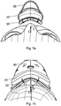
- Fig. 7 shows a sectional view of the mask position seen from the chin side to illustrate the situation of the patient's nose just before biasing the mask cushion inward to achieve the clamping effect.
- Fig. 7b shows a non cross-sectional view of the same mask position being applied to the patient's face, seen from the forehead side
- the arrows indicate deformation and/or movement of the pad and cushion at the nose ridge, preferably at the nasal bones, lateral cartilage and/or sepal cartilage, of the patient.
- Figs. 8 shows cross sectional views of a pad at a position as indicated in Fig. 9b .
- Fig. 9 shows top views on (parts of) preferred sealing flange portion.
- Fig. 10 shows three dimensional views of an exemplary mask in line with the present technology wherein Fig. 10a shows a diagonal front view, Fig. 10b sows a diagonal back view and Fig. 10c shows a side view.
- Fig. 11 shows a preferred cushion and pad according to the present technology, wherein Fig. 11a shows a side view, Fig. 11b shows a cross sectional side view, Fig. 11c shows detail A of Fig. 11b and Fig. 11d shows detail B of Fig. 11b .
- Fig. 12 shows different three dimensional cross sectional views of preferred pads of the present technology and enlarged details thereof.
- Fig. 13 shows a side view of the mask in use.
- the patient interface 3000 with a frame member 30 may be, preferably removably, held by a frame element comprising the forehead support 3700.
- the curved arrows indicate the movement of the upper portion of the pad 10 and/or the cushion 20, i.e. the movement of the apex P, while being positioned on the nose.
- the rotational, rocking and/or pivoting movement inwards to the plenum chamber 3200 may occur simultaneously to the movement in the direction D depicted in figure 5 .
- the portion contacting the nose ridge as well as directly adjacent left and/or right portions of the pad 10 and/or cushion 20 may rotationally move upon insertion of the nose into the plenum chamber 3200.
- the direction of the movement of the portion contacting the nose ridge as well as directly adjacent left and/or right portions may differ.
- the clamping region (here shown as a dashed line) may also be located at other locations not depicted in Fig
- the present technology comprises apparatus for treating a respiratory disorder.
- the apparatus may comprise a flow generator or blower for supplying pressurised respiratory gas, such as air, to the patient via an air delivery tube leading to a patient interface 3000.
- a non-invasive patient interface 3000 in accordance with one aspect of the present technology comprises the following functional aspects: a seal-forming structure 3100, a plenum chamber 3200, a positioning and stabilising structure 3300 and a connection port 3600 for connection to air circuit 4170 ( Fig. 1b , 3 , 4 ).
- a functional aspect may be provided by one or more physical components.
- One physical component may provide one or more functional aspects.
- the seal-forming structure 3100 may be arranged to surround an entrance to the airways of the patient so as to facilitate the supply of air at positive pressure to the airways.
- a seal-forming structure 3100 may provide a sealing-forming portion 11, preferably provided on a pad 10, and a cushion 20.
- the cushion may at least partially provide a cushioning function.
- a seal-forming structure 3100 in accordance with the present technology may be constructed from a soft, flexible, resilient material such as silicone.
- the seal-forming structure 3100 may comprise in a portion of the cushion a sealing flange and a support flange.
- the sealing flange comprises a relatively thin member with a thickness of, e.g., less than about 1mm, for example about 0.25mm to about 0.45mm, that extends around the perimeter 3210 of the plenum chamber 3200.
- the support flange may be relatively thicker than the sealing flange.
- the support flange may be disposed between the sealing flange and the marginal edge of the plenum chamber 3200, and may extend at least part of the way around the perimeter 3210.
- the support flange preferably is or includes a spring-like element and functions to support the sealing flange from buckling in use. In use the sealing flange may readily respond to system pressure in the plenum chamber 3200 acting on its underside to urge it into tight sealing engagement with the face.
- the seal-forming portion of the non-invasive patient interface 3000 may comprise a pair of nasal puffs, or nasal pillows, each nasal puff or nasal pillow being constructed and arranged to form a seal with a respective naris of the nose of a patient.
- Nasal pillows in accordance with an aspect of the present technology include: a frusto-cone, at least a portion of which forms a seal on an underside of the patient's nose; a stalk, a flexible region on the underside of the cone and connecting the cone to the stalk.
- the structure to which the nasal pillow of the present technology is connected includes a flexible region adjacent the base of the stalk.
- the flexible regions can act in concert to facilitate a universal joint structure that is accommodating of relative movement- both displacement and angular- of the frusto-cone and the structure to which the nasal pillow is connected.
- the frusto-cone may be axially displaced towards the structure to which the stalk is connected.
- the non-invasive patient interface 3000 may comprise a seal-forming portion that forms a seal in use on an upper lip region (that is, the lip superior ) of the patient's face.
- the non-invasive patient interface 3000 may comprise a seal-forming portion that forms a seal in use on a chin-region of the patient's face.
- Figure 2 discloses three seal forming portions 11 in accordance with preferred alternative or combined technologies of the disclosed technology.
- the seal forming portions may be manufactured using one of the disclosed methods.
- Left seal forming portion 11 comprises fibers 112 extending from the surface of resilient material 114. Fibers 112 are fixed to surface 112 with an adhesive 113. Fibers 112 form an angle ⁇ with the base surface of approximately 90°. Often, the fibers 112 will be randomly distributed.
- the second seal forming portion located in the middle of Fig. 2 comprises fibers 112' arranged in a plurality of tufts. The tufts are looped at the second free end adapted to get in contact with a patient. The looped distal ends provide an increased wearing comfort.
- seal forming portion 11 is depicted in the Figures in conjunction with the particularly advantageous cushion 20 and pad 10, seal forming portions 11 may also be used with other pads and/or other cushions.
- Figures 3 to 8 and 10 to 11 show pad 10 arranged on cushion 20 of patient interface 3000.
- the pad may be manufactured using one of the disclosed methods.
- pad 10 extends along the entire perimeter 3210 of the plenum chamber, i.e. the perimeter of the entrance to the airways of the patient.
- Pad 10 is generally flat. That is, the width w 10 of the pad is significantly greater than its thickness t 10 .
- the front or face contacting surface 11 is contacting the user and forms the seal against the user's face.
- face contacting surface 11 preferably comprises the above described seal forming portion 11 with fibers 112.
- the back surface of pad 10 is adapted to contact cushion 20 in cushion contacting portion 13.
- the lateral side surfaces at lateral sides 101, 102 may be generally round.
- Figure 12 depicts further preferred shapes of pad 10. Details C and E depict rounded lateral sides 101, 102 whereas the sides of details D and F are generally flat. Overall, details D and F have a flat and rather rectangular of trapezoid shape. The shape may be influenced by the manufacturing process.
- Figure 12 shows on the top left a cross sectional three dimensional view of a pad 10 according to the present technology wherein right below an enlarged detail C of said pad is shown. Similarly, the pads shown on the top right, bottom left and bottom right of Fig. 12 show preferred cushions according to the present technology with respective enlarged details of a cross sectional section thereof.
- the outer circumferential side surface 102 of the cushion may be substantially flat, as, e.g., shown in the top right example, or curved, as shown, e.g., in the top left example.
- the example on the bottom left shows a rounded outer circumferential surface 102 in combination with a straight inner circumferential surface 101 having a radius, preferably corresponding to about 1/8 to 1 ⁇ 2 of the pad thickness, at the transition to the seal forming portion or surface 11. This may ease the comfort of the pad when worn by a user.
- the pads on the top left and right as well as the bottom left show a substantially flat or planar, eventually slightly concave seal forming portion 11, the pad depicted at the bottom right (see detail F) is exhibits a convexly curved cross-sectional profile.
- Figures. 8a, 8ab are cross sectional views as indicated in Fig. 9b , i.e. views perpendicular to the circumferential direction 3210.
- pad 10 may have different cross-sectional shapes.
- cushion contacting portion 13 may be configured to be generally flat while face contacting portion 11 may have a profiled shape.
- Face contacting portion 11 may have a first concave cross sectional portion followed by a convex peak cross sectional portion and a second concave cross section portion ( Fig. 8a and detail F in Fig. 12 ).
- the cross sectional shape may be configured as a convex shape with a gradually reduced gradient towards the outer section of pad 10 as shown in Fig. 8b . Any suitable 2.5D configuration may be applied.
- flange portion 26 may be provided with a slit 15 reducing the stiffness of flange portion 26. Portions adjacent to slit 15 at apex P of flange portion 26 depicted in Fig. 9a and located in the nose receiving portion may easier move relative to each other. Such a configuration may facilitate the clamping ( Figs. 5 , 7 ). As shown in Fig. 9b , pad 10 may be provided with a corresponding notch or pad slit 15, too.
- the pad is provided with a high resilience and is configured to micro-adapt to the patient's face and/or to follow the movements of cushion 20, e.g. pivoting movements of flange 26 depicted in Fig. 5 , 7 .
- the pivoting movements of flange 26 together with other suitable deformations of the cushion achieve a macro-adaptation to the contour and physiognomy of a patients face while the pad provides for a micro-adaptation to said face to enhance, e.g., comfort, sealing characteristics and thus compliance.
- pad 10 is depicted in the Figures in conjunction with the particularly advantageous seal forming portion 11 and cushion 20, pad 10 may also be used with other cushions and/or other seal forming portions.
- Fig. 5 is an enlarged view of the apex region P depicted in Fig. 4 .
- Cushion 20 supports pad 10 which is positioned at flange 26.
- the depicted mask comprising cushion 20 and pad 10 may be manufactured using one of the disclosed methods.
- Flange 26 and web 24 together form a T- or I-shaped beam shape or structure 22.
- the first end A of structure 22 is fixed to shell or frame 30 of patient interface 3000.
- a generally chevron- or V-shaped flange of shell or frame 30 is connected to first end A of web portion 24, for instance by co-molding.
- Part of the shell may also be made of the cushion material. I.e. the cushion may continue to the front area of the patient interface forming part of the shell.
- Shell or frame 30 may be integrally molded with cushion 20 ( Figs. 3 to 7 ). As indicated by arrows in Fig. 5 , at least a portion of flange 26, preferably the whole flange 26 may pivot or rock around the second end B. Pad 10 is adapted to follow this movement. When a patient first contacts pad 10 at or close to inner or lateral side 101 pad 10 and flange 26 may pivot around second end B and inner side 101 may move generally in direction C. Depending on the individual shape of the patient's face, it may also be the case that it first contacts the pad at or close to the outer side. In this case, pad 10 and flange 26 may pivot around second end B towards the outer side, opposite direction of C.
- the cushion and pad due to their resilience and spring features, may be adapted to cope with and tolerate the resulting torsion as adjacent parts bend inwardly or outwardly.
- This mechanism allows the system to adapt itself to the patient's individual anatomical distinctiveness in a particularly advantageous fashion.
- Direction C is opposite the application direction during positioning the mask. I.e. at inner side 101 pad 10 generally moves toward the inner part of cushion 20 (meaning toward the plenum chamber 3200).
- portions of first arm 261 move in generally the same direction.
- portions of second 262 arm may move simultaneously in the opposite direction. I.e. generally in the application direction of the patient interface or towards the patient's face as indicated by curved arrows in Fig. 5 .
- the second end B of web 24 is a center around which the two arms 261, 262 of flange 26 may rock. This rocking motion may be suitable to ensure a near-constant application of the required sealing force onto the patient's face over the entire pad surface, while simultaneously avoiding local areas of increased force.
- the resilience of cushion 20 is influenced by the configuration of the first and second arms 261, 261.
- Fig. 5 and 6 show the configuration in the apex P region of patient interface 3000.
- the configuration of the T- or I-beam structured rocker may vary around the perimeter of the entrance to the patient's airways.
- arm 261 may be configured more pliable and/or longer in a portion of sealing structure 3100 where a high resilience is required whereas arm 261 may be shorter and/or stiffer in a portion of the sealing structure 3100 which may transmit more interface holding forces to a patient's face.
- the relative position of the rocker center or second end B may also vary around the perimeter aiming to influence the resilience.
- the second end B may be located more toward to outer side 102 of flange 26 in portions of sealing structure 3100 in which a high resilience is required than in portions of the sealing structure which may transmit more interface holding forces to a patient's face.
- the location of the second end B on the flange structure may influence the behavior of the rocking motion in such a way that the system will, in specific areas, more readily deflect towards the mask interior or towards the mask exterior. This may be advantageous in that in protruding areas such as, e.g., the nose ridge or chin, the cushion and pad will be able to deflect towards the interior, whereas in flatter areas such as, e.g., the cheeks, the cushion may be more poised to bend outward.
- the first arm length or width is referred to as w 261 while the second arm length or width is referred to as w 262 .
- the second arm width is smaller or shorter than the first arm width.
- the simple basic design may allow the use of relatively simple manufacturing processes discussed above without compromising on the comfort.
- flange 26 may only comprise a first arm 261 having portions provided with different arm length and/or different arm stiffnesses thereby varying the resilience of the cushion 20 along the perimeter 3210. By varying the length and/or the stiffness of arm 261, a portion of the first arm 261 located in the nose receiving region may be provided with a higher resilience than another region not located in the nose receiving portion.
- Web portion 24 may have an elasticity so as to allow together with above rocker function a clamping onto the patient's nose ridge, preferably on the nasal bones, lateral cartilage and/or sepal cartilage ( Figs. 11 , 5 , 7 , 11 ) thereby improving the seal.
- Web portion 24 may be adapted to not significantly collapse when the patient contacts inner side 101.
- Web portion 24 may be adapted to bulge or move, preferably in a direction D, direction D being generally perpendicular to the main axis of extension of web 24.
- Web portion 24 may be adapted to move center B of the rocking movement of flange 26 more in a lateral direction D than in the direction of extension of web 24.
- the web 24 is shaped to form a bulge or bellows around the entire perimeter (e.g. Figs. 11 ).
- This bellows is most prominent (e.g. having a smaller radius) where a high resilience is required (e.g. at the nose), and least prominent (e.g. having a bigger radius) where a high stiffness is required (e.g. in the cheeks area).
- the bulge/bellows will allow the cushion to deflect as the pad comes into contact with prominent features such as the nose.
- the point B moves roughly in the direction of C, causing the pad and flange features to be pulled inwards in a proximal direction, towards the nose ridge of the patient.
- the combination of these two effects enables the mask to create a seal by transforming the sealing force, which is applied in a ventral-dorsal plane by the headgear, into a force acting onto the sides of the nose in a proximal direction.
- This lateral movement of the second end B may further facilitate the clamping of cushion 20 and/or pad 10 onto the patient's nose.
- the laterally displaced rocking center B of web 24 may be biased causing a clamping force on lateral sides of the nose.
- Cushion 20 and/or pad 10 are provided with a portion of reduced stiffness, here configured as a slit 15.
- the first and/or second flanges may be provided with at least two portions of different materials.
- the first arm 261 may comprise two portions 261-1, 261-2 of different materials.
- the first portion proximate to second end B may be made of a first material whereas the second distal portion 261-2 may be made of the second material.
- the first material may be less resilient than the second material.
- the portions of different materials may be provided around the entire perimeter 3210 of the plenum chamber 3200.
- the portions of different materials are located in sensible areas, e.g. proximal to / around the nose bridge. These portions of different materials may constitute or contribute to the zones of reduce stiffness discussed above.
- cushion 20 is depicted in the Figures in conjunction with the particularly advantageous seal forming portion 11 and pad 10, cushion 20 may also be used with other pads and/or other seal forming portions.
- the plenum chamber 3200 has a perimeter 3210 that is shaped to be complementary to the surface contour of the face of an average person in the region where a seal will form in use.
- a marginal edge 3220 of the plenum chamber 3200 is positioned in close proximity to an adjacent surface of the face. Actual contact with the face is provided by the seal-forming structure 3100.
- the seal-forming structure 3100 extends in use about the entire perimeter 3210 of the plenum chamber 3200.
- the seal-forming portion 3100 of the patient interface 3000 of the present technology is held in sealing position in use by the positioning and stabilising structure 3300 such as a headgear 3300.
- the patient interface 3000 includes a vent 3400 constructed and arranged to allow for the washout of exhaled carbon dioxide.
- vent in accordance with the present technology comprises a plurality of holes, for example, about 20 to about 80 holes, or about 40 to about 60 holes, or about 45 to about 55 holes.
- the vent is located in the plenum chamber.
- the vent is located in a decoupling structure, e.g. a swivel.
- the patient interface 3000 includes at least one decoupling structure, for example a swivel or a ball and socket.
- Connection port allows for connection to the air circuit.
- the patient interface 3000 includes a forehead support.
- the patient interface includes an anti-asphyxia valve.
- a patient interface 3000 includes one or more ports that allow access to the volume within the plenum chamber. In one form this allows a clinician to supply supplemental oxygen. In one form this allows for the direct measurement of a property of gases within the plenum chamber, such as the pressure.
- Silicone or Silicone Elastomer A synthetic rubber.
- a reference to silicone is a reference to liquid silicone rubber (LSR) or a compression moulded silicone rubber (CMSR).
- LSR liquid silicone rubber
- CMSR compression moulded silicone rubber
- SILASTIC included in the range of products sold under this trademark
- Another manufacturer of LSR is Wacker.
- a preferred form of LSR has a Shore A (or Type A) indentation hardness in the range of about 35 to about 45 as measured using ASTM D2240
- Polycarbonate a typically transparent thermoplastic polymer of Bisphenol-A Carbonate.
- Frame 30 Frame will be taken to mean a mask structure that bears the load of tension between two or more points of connection with a headgear.
- a mask frame may be a non-airtight load bearing structure in the mask. However, some forms of mask frame may also be air-tight.
- Plenum chamber a mask plenum chamber will be taken to a mean portion of a patient interface having walls enclosing a volume of space, the volume having air therein pressurised above atmospheric pressure in use.
- a shell may form part of the walls of a mask plenum chamber.
- a region of the patient's face forms one of the walls of the plenum chamber.
- Seal The noun form ("a seal") will be taken to mean a structure or barrier that intentionally resists the flow of air through the interface of two surfaces.
- the verb form (“to seal”) will be taken to mean to resist a flow of air.
- a shell will preferably be taken to mean a curved structure having bending, tensile and compressive stiffness, for example, a portion of a mask that forms a curved structural wall of the mask. Preferably, compared to its overall dimensions it is relatively thin. In some forms, a shell may be faceted. Preferably such walls are airtight, although in some forms they may not be airtight.
- Shell and frame may be configured as one part, either called frame or shell.
- Curvature (of a surface) A region of a surface having a saddle shape, which curves up in one direction and curves down in a different direction, will be said to have a negative curvature. A region of a surface having a dome shape, which curves the same way in two principle directions, will be said to have a positive curvature. A flat surface will be taken to have zero curvature.
- Resilient Able to deform substantially elastically, and to release substantially all of the energy upon unloading, within a relatively short period of time such as 1 second.
- Semi-rigid means being sufficiently rigid to not substantially distort under the effects of mechanical forces typically applied during positive airway pressure therapy.
- the nasal ridge is the midline prominence of the nose, extending from the Sellion to the Pronasale.
- Lateral nasal cartilage A generally triangular plate of cartilage. Its superior margin is attached to the nasal bone and frontal process of the maxilla, and its inferior margin is connected to the greater alar cartilage.
- Nasal bones The nasal bones are two small oblong bones, varying in size and form in different individuals; they are placed side by side at the middle and upper part of the face, and form, by their junction, the "bridge" of the nose.
- Lateral nasal cartilage A generally triangular plate of cartilage. Its superior margin is attached to the nasal bone and frontal process of the maxilla, and its inferior margin is connected to the greater alar cartilage.
- Septal cartilage (nasal) : The nasal septal cartilage forms part of the septum and divides the front part of the nasal cavity.
- the present invention also covers the exact terms, features, values and ranges etc. in case these terms, features, values and ranges etc. are used in conjunction with terms such as about, around, generally, substantially, essentially, at least etc. (i.e., "about 3” shall also cover exactly 3 or "essentially radial” shall also cover exactly radial).
Claims (11)
- Patientenschnittstelle (3000) mit einem Dichtungsbildungsabschnitt (11) zum Berühren der Haut eines Benutzers, einem Polster (10) und einem Maskenkissen (20); wobei das Polster (10) eine elastische Schaummaterialschicht aufweist, die eine Grundfläche (111) des Dichtungsbildungsabschnitts (11) bildet, wobei das Polster (10) geeignet ist, mit dem Maskenkissen (20) verbunden zu sein,
wobei der Dichtungsbildungsabschnitt (11) die Grundfläche (111) und mehrere Fasern (112) aufweist, die an der Grundfläche (111) befestigt sind und sich von ihr weg zum Kontaktieren der Haut eines Patienten erstrecken;
wobei das Maskenkissen (20) mindestens entlang eines Teils des Umfangs eine erste Struktur (22) aufweist, die einen länglichen Abschnitt (24) hat, der mit mindestens einem Endabschnitt (26) verbunden ist, der im Wesentlichen senkrecht oder in einem Winkel zum länglichen Abschnitt (24) orientiert ist,
wobei ein erstes Ende (A) des länglichen Abschnitts (24) mit einem Rahmenteil (30) verbunden oder verbindbar ist,
wobei der Endabschnitt (26) an einem gegenüberliegenden zweiten Ende (B) des länglichen Abschnitts (24) vorgesehen ist,
wobei die erste Struktur (22) eine T-trägerförmige Struktur (22) ist,
wobei der längliche Abschnitt (24) ein Stegteil (24) ist und der Endabschnitt (26) ein Flanschteil (26) ist,
wobei das Polster (10) mit dem Flanschteil (26) verbunden ist,
wobei der Flanschteil (26) zwei Arme (261, 262) aufweist, die sich vom zweiten Ende (B) des Stegteils (24) in Seitenrichtung erstrecken, und
wobei der erste und/oder zweite Arm geeignet sind/ist, relativ zum zweiten Ende (B) zu drehen. - Patientenschnittstelle (3000) nach Anspruch 1, wobei der Flanschteil (26) eingerichtet ist, um das zweite Ende (B) zu schwingen, wobei die beiden Arme (261, 262) des Flanschteils (26) die Schwingenarme sind, wobei der Flanschteil (26) eingerichtet ist, um das zweite Ende (B) zu schwingen, wenn die Haut des Patienten, vorzugsweise über einen Abschnitt des Polsters (10) mit dem ersten und/oder zweiten Arm (261, 262) in Kontakt steht.
- Patientenschnittstelle (3000) nach Anspruch 1 oder 2, wobei der Flanschteil (26) eingerichtet ist, um das zweite Ende (B) zu schwingen, und wobei das Maskenkissen (20), insbesondere der Stegteil (24), mit einer Elastizität in einem Nasenaufnahmeabschnitt des Maskenkissens (20) versehen ist, um das Maskenkissen (20) auf den Rücken der Nase des Patienten zu klemmen.
- Patientenschnittstelle (3000) nach einem der Ansprüche 1 bis 3, wobei der Stegteil (24) eingerichtet ist, sich in Seitenrichtung (D) zu wölben.
- Patientenschnittstelle (3000) nach einem der Ansprüche 1 bis 4, wobei das Maskenkissen (20) mindestens eine Balgstruktur und/oder vorzugsweise nach außen orientierte und vorgeformte Wölbungen aufweist, die vorzugsweise in einem Nasenaufnahmeabschnitt liegt und/oder vorzugsweise im Stegteil (24) angeordnet ist.
- Patientenschnittstelle (3000) nach einem der Ansprüche 1 bis 5, wobei die Faser vom nahen Ende zum distalen Ende gemessen eine Länge (l112) zwischen etwa 0,01 und 5,0 mm, stärker bevorzugt zwischen etwa 0,05 mm und 2,0 mm und am stärksten bevorzugt zwischen etwa 0,1 mm und 1,0 mm hat.
- Patientenschnittstelle (3000) nach einem der Ansprüche 1 bis 6, wobei die mehreren Fasern (112) für eine höhere Elastizität im Nasenrückenbereich als in anderen Bereichen des Dichtungsbildungsabschnitts (11) sorgen.
- Patientenschnittstelle (3000) nach einem der Ansprüche 1 bis 7, wobei die mehreren Fasern (112) aus einem Bestandteil aus der Gruppe hergestellt sind, die aus Baumwolle, Wolle, Viskose, Nylon und Zellulose besteht.
- Patientenschnittstelle (3000) nach einem der Ansprüche 1 bis 8, wobei das Polster (10) eine Polsterdicke (t10) zwischen etwa 1,5 mm bis 26 mm, vorzugsweise zwischen etwa 3,0 mm und 13 mm hat.
- Patientenschnittstelle (3000) nach einem der Ansprüche 1 bis 9, wobei das Polster (10) mit einer höheren Elastizität als das Maskenkissen (20) versehen ist, wobei das Maskenkissen (20) vorzugsweise mit einer Elastizität versehen ist, um sich allgemein an die individuelle Form des Gesichts eines Patienten anzupassen.
- Patientenschnittstelle (3000) nach einem der Ansprüche 1 bis 10, wobei das Polster (10) einen Abschnitt mit reduzierter Steifigkeit aufweist, vorzugsweise im Scheitel (P) des Polsters (10), um vorzugsweise Relativbewegung von Abschnitten des Polsters (10) benachbart zur Nasenregion des Patienten zu erleichtern.
Priority Applications (4)
| Application Number | Priority Date | Filing Date | Title |
|---|---|---|---|
| EP14172818.8A EP2957314B1 (de) | 2014-06-17 | 2014-06-17 | Dichtungsbildungsabschnitt, Kissen und Polster für eine Patientenschnittstelle |
| US14/741,930 US10207070B2 (en) | 2014-06-17 | 2015-06-17 | Seal forming portion, pad and cushion for a patient interface and method of manufacturing |
| US16/227,779 US11529484B2 (en) | 2014-06-17 | 2018-12-20 | Seal forming portion, pad and cushion for a patient interface and method of manufacturing |
| US18/051,894 US20230072407A1 (en) | 2014-06-17 | 2022-11-02 | Seal forming portion, pad and cushion for a patient interface and method of manufacturing |
Applications Claiming Priority (1)
| Application Number | Priority Date | Filing Date | Title |
|---|---|---|---|
| EP14172818.8A EP2957314B1 (de) | 2014-06-17 | 2014-06-17 | Dichtungsbildungsabschnitt, Kissen und Polster für eine Patientenschnittstelle |
Publications (2)
| Publication Number | Publication Date |
|---|---|
| EP2957314A1 EP2957314A1 (de) | 2015-12-23 |
| EP2957314B1 true EP2957314B1 (de) | 2018-03-21 |
Family
ID=51059273
Family Applications (1)
| Application Number | Title | Priority Date | Filing Date |
|---|---|---|---|
| EP14172818.8A Active EP2957314B1 (de) | 2014-06-17 | 2014-06-17 | Dichtungsbildungsabschnitt, Kissen und Polster für eine Patientenschnittstelle |
Country Status (2)
| Country | Link |
|---|---|
| US (3) | US10207070B2 (de) |
| EP (1) | EP2957314B1 (de) |
Families Citing this family (16)
| Publication number | Priority date | Publication date | Assignee | Title |
|---|---|---|---|---|
| US10603456B2 (en) | 2011-04-15 | 2020-03-31 | Fisher & Paykel Healthcare Limited | Interface comprising a nasal sealing portion |
| US11419999B2 (en) | 2013-08-05 | 2022-08-23 | Fisher & Paykel Healthcare Limited | Seal for a patient interface, interface assemblies and aspects thereof |
| US11707588B2 (en) * | 2014-05-06 | 2023-07-25 | Koninklijke Philips N.V. | Determining patient interface device optimal hardness |
| US10232137B2 (en) * | 2014-05-22 | 2019-03-19 | Resmed Limited | Patient interface |
| SG10201811277XA (en) | 2014-06-17 | 2019-01-30 | Fisher & Paykel Healthcare Ltd | Patient interfaces |
| EP2957314B1 (de) | 2014-06-17 | 2018-03-21 | ResMed Ltd. | Dichtungsbildungsabschnitt, Kissen und Polster für eine Patientenschnittstelle |
| WO2016108116A1 (en) * | 2014-12-30 | 2016-07-07 | Koninklijke Philips N.V. | Sealing cushion for a patient interface device that has a custom cushion support assembly |
| US10994090B2 (en) | 2015-09-04 | 2021-05-04 | Fisher & Paykel Healthcare Limited | Patient interfaces |
| EP3146991B1 (de) * | 2015-09-25 | 2022-01-26 | ResMed Pty Ltd | Patientenschnittstellenkomponenten |
| US11167103B2 (en) * | 2016-01-14 | 2021-11-09 | ResMed Pty Ltd | Oro-nasal patient interface |
| WO2018065926A1 (en) | 2016-10-05 | 2018-04-12 | Fisher & Paykel Healthcare Limited | Patient interfaces |
| US11369764B2 (en) * | 2017-03-03 | 2022-06-28 | Fisher & Paykel Healthcare Limited | Overmolded textile cushion |
| AU2018201087B1 (en) * | 2017-05-08 | 2018-04-26 | P & M Hebbard Pty Ltd | Improvements for respiratory masks |
| USD884153S1 (en) | 2018-04-04 | 2020-05-12 | Fisher & Paykel Healthcare Limited | Frame for a mask assembly |
| WO2021123897A1 (en) * | 2019-12-20 | 2021-06-24 | ResMed Asia Pte Ltd | Patient interface with foam cushion |
| US20220175064A1 (en) * | 2020-12-07 | 2022-06-09 | Abacus Investment LLC | Sealing cushion for a protective face mask |
Family Cites Families (36)
| Publication number | Priority date | Publication date | Assignee | Title |
|---|---|---|---|---|
| US3688768A (en) * | 1971-03-04 | 1972-09-05 | Johns Manville | Disposable face respirator and method of making same |
| EP0044130B1 (de) * | 1980-07-11 | 1985-05-15 | Imperial Chemical Industries Plc | Schichtstoffe aus Kunststoffschaum |
| WO1982003548A1 (en) | 1981-04-24 | 1982-10-28 | Sullivan Colin Edward | Device for treating snoring sickness |
| US4600002A (en) * | 1984-10-24 | 1986-07-15 | American Optical Corporation | Disposable respirator |
| US4951664A (en) * | 1988-09-09 | 1990-08-28 | Filcon Corporation | Mask and method of manufacture |
| US5096760A (en) * | 1989-07-20 | 1992-03-17 | Creme Art Corporation | Covered soft foam article |
| US5307796A (en) * | 1990-12-20 | 1994-05-03 | Minnesota Mining And Manufacturing Company | Methods of forming fibrous filtration face masks |
| US6513526B2 (en) * | 1996-07-26 | 2003-02-04 | Resmed Limited | Full-face mask and mask cushion therefor |
| AUPO126596A0 (en) | 1996-07-26 | 1996-08-22 | Resmed Limited | A nasal mask and mask cushion therefor |
| AUPP366398A0 (en) | 1998-05-22 | 1998-06-18 | Resmed Limited | Ventilatory assistance for treatment of cardiac failure and cheyne-stokes breathing |
| DE19954517C2 (de) | 1999-11-12 | 2002-01-31 | Map Gmbh | Atemmaske und Verfahren zur Herstellung derselben |
| EP2308537A1 (de) | 2002-06-14 | 2011-04-13 | MAP Medizin-Technologie GmbH | Maskenkissen für eine Atemmaske |
| EP2913079B1 (de) * | 2002-09-06 | 2017-10-25 | ResMed Limited | Kissen für atemmaskenanordnung |
| ATE538832T1 (de) * | 2003-05-05 | 2012-01-15 | Resmed Ltd | Stirnstütze für eine gesichtsmaske |
| DE202006021251U1 (de) | 2005-01-12 | 2014-03-24 | Resmed Limited | Polster für Patientenschnittstelle |
| US20080053450A1 (en) * | 2006-08-31 | 2008-03-06 | Nellcor Puritan Bennett Incorporated | Patient interface assembly for a breathing assistance system |
| US8779016B2 (en) * | 2006-12-29 | 2014-07-15 | Owens Corning Intellectual Capital, Llc | Spray-in latex foam for sealing and insulating |
| US10410991B2 (en) * | 2007-08-06 | 2019-09-10 | Immunolight, Llc | Adhesive bonding composition and method of use |
| US8291906B2 (en) | 2008-06-04 | 2012-10-23 | Resmed Limited | Patient interface systems |
| US9901699B2 (en) | 2008-06-04 | 2018-02-27 | Resmed Limited | Pad for a mask |
| EP2313137B1 (de) * | 2008-08-04 | 2017-10-11 | Fisher & Paykel Healthcare Limited | Verschlussschnittstelle für eine atemmaske |
| EP2213324B1 (de) * | 2009-01-30 | 2016-07-27 | ResMed R&D Germany GmbH | Patientenschnittstellenstruktur und Verfahren/Werkzeug zu ihrer Herstellung |
| EP2424605B1 (de) * | 2009-04-27 | 2013-06-05 | Tomtec N.V. | Tragbare medizinische Halterung zur Abgabe von Flüssigkeiten an die Nase |
| JP5823378B2 (ja) | 2009-05-29 | 2015-11-25 | レスメド・リミテッドResMedLimited | 鼻マスクシステム |
| US20110209701A1 (en) * | 2010-03-01 | 2011-09-01 | Laura Derringer | Nose pad cushion and applicator for respiratory mask |
| CN103068431B (zh) * | 2010-09-01 | 2015-11-25 | 瑞思迈有限公司 | 面罩系统 |
| US9517320B2 (en) * | 2010-10-08 | 2016-12-13 | Resmed Limited | Unobtrusive nasal mask |
| EP2632397B1 (de) | 2010-10-26 | 2016-12-14 | 5I Sciences, Inc. | Vorrichtung und verfahren zur atemwegsöffnung |
| EP2691058B1 (de) | 2011-03-29 | 2016-03-02 | ResMed R&D Germany GmbH | Kissen für eine patientenschnittstelle |
| CN103635220B (zh) * | 2011-06-30 | 2017-03-22 | 皇家飞利浦有限公司 | 提供改进的负载分配功能的用户界面装置 |
| CN107252515B (zh) * | 2011-07-12 | 2020-06-02 | 瑞思迈私人有限公司 | 纺织物面罩系统 |
| US20140311496A1 (en) * | 2011-11-03 | 2014-10-23 | Koninklijke Philips N.V. | Patient interface having headgear post for clip or strap |
| US10028859B2 (en) * | 2012-03-27 | 2018-07-24 | Koninklijke Philips N.V. | User interface device providing for improved cooling of the skin |
| US10596340B2 (en) | 2014-06-17 | 2020-03-24 | ResMed Pty Ltd | Seal forming structure for a patient interface and a tool and method of manufacturing the seal forming structure |
| EP2957314B1 (de) | 2014-06-17 | 2018-03-21 | ResMed Ltd. | Dichtungsbildungsabschnitt, Kissen und Polster für eine Patientenschnittstelle |
| EP3146991B1 (de) * | 2015-09-25 | 2022-01-26 | ResMed Pty Ltd | Patientenschnittstellenkomponenten |
-
2014
- 2014-06-17 EP EP14172818.8A patent/EP2957314B1/de active Active
-
2015
- 2015-06-17 US US14/741,930 patent/US10207070B2/en active Active
-
2018
- 2018-12-20 US US16/227,779 patent/US11529484B2/en active Active
-
2022
- 2022-11-02 US US18/051,894 patent/US20230072407A1/en active Pending
Non-Patent Citations (1)
| Title |
|---|
| None * |
Also Published As
| Publication number | Publication date |
|---|---|
| US20160001029A1 (en) | 2016-01-07 |
| US20230072407A1 (en) | 2023-03-09 |
| US10207070B2 (en) | 2019-02-19 |
| EP2957314A1 (de) | 2015-12-23 |
| US20190117924A1 (en) | 2019-04-25 |
| US11529484B2 (en) | 2022-12-20 |
Similar Documents
| Publication | Publication Date | Title |
|---|---|---|
| US20230072407A1 (en) | Seal forming portion, pad and cushion for a patient interface and method of manufacturing | |
| US20210370002A1 (en) | Respiratory apparatus | |
| US11666721B2 (en) | Oro-nasal patient interface | |
| US20200384232A1 (en) | Patient interface | |
| US10004867B2 (en) | Respiratory apparatus | |
| US11338103B2 (en) | Headgear for a patient interface | |
| EP3193992A1 (de) | Gasauswaschentlüftung für patientenschnittstelle | |
| US20220401681A1 (en) | Vents for patient interfaces | |
| US20220395660A1 (en) | Modular patient interface including a joint coupling mouth and nasal cushions | |
| US20230073765A1 (en) | Patient interface system | |
| US20240042152A1 (en) | Patient interface | |
| US20230191066A1 (en) | Apparatus, systems and methods for positioning and stabilising a patient interface | |
| WO2023164747A1 (en) | Positioning and stabilising structure with patient contacting portions | |
| WO2023230667A1 (en) | Patient interface | |
| WO2023282852A2 (en) | A patient interface and a positioning and stabilising structure for a patient interface | |
| EP3178512A1 (de) | Anpassbare patientenschnittstelle | |
| NZ761302B2 (en) | Respiratory Apparatus |
Legal Events
| Date | Code | Title | Description |
|---|---|---|---|
| PUAI | Public reference made under article 153(3) epc to a published international application that has entered the european phase |
Free format text: ORIGINAL CODE: 0009012 |
|
| AK | Designated contracting states |
Kind code of ref document: A1 Designated state(s): AL AT BE BG CH CY CZ DE DK EE ES FI FR GB GR HR HU IE IS IT LI LT LU LV MC MK MT NL NO PL PT RO RS SE SI SK SM TR |
|
| AX | Request for extension of the european patent |
Extension state: BA ME |
|
| 17P | Request for examination filed |
Effective date: 20160623 |
|
| RBV | Designated contracting states (corrected) |
Designated state(s): AL AT BE BG CH CY CZ DE DK EE ES FI FR GB GR HR HU IE IS IT LI LT LU LV MC MK MT NL NO PL PT RO RS SE SI SK SM TR |
|
| 17Q | First examination report despatched |
Effective date: 20170116 |
|
| GRAP | Despatch of communication of intention to grant a patent |
Free format text: ORIGINAL CODE: EPIDOSNIGR1 |
|
| INTG | Intention to grant announced |
Effective date: 20171013 |
|
| GRAS | Grant fee paid |
Free format text: ORIGINAL CODE: EPIDOSNIGR3 |
|
| GRAA | (expected) grant |
Free format text: ORIGINAL CODE: 0009210 |
|
| AK | Designated contracting states |
Kind code of ref document: B1 Designated state(s): AL AT BE BG CH CY CZ DE DK EE ES FI FR GB GR HR HU IE IS IT LI LT LU LV MC MK MT NL NO PL PT RO RS SE SI SK SM TR |
|
| REG | Reference to a national code |
Ref country code: GB Ref legal event code: FG4D |
|
| REG | Reference to a national code |
Ref country code: CH Ref legal event code: EP |
|
| REG | Reference to a national code |
Ref country code: AT Ref legal event code: REF Ref document number: 980438 Country of ref document: AT Kind code of ref document: T Effective date: 20180415 |
|
| REG | Reference to a national code |
Ref country code: IE Ref legal event code: FG4D |
|
| REG | Reference to a national code |
Ref country code: DE Ref legal event code: R096 Ref document number: 602014022516 Country of ref document: DE |
|
| REG | Reference to a national code |
Ref country code: FR Ref legal event code: PLFP Year of fee payment: 5 |
|
| REG | Reference to a national code |
Ref country code: NL Ref legal event code: MP Effective date: 20180321 |
|
| PG25 | Lapsed in a contracting state [announced via postgrant information from national office to epo] |
Ref country code: CY Free format text: LAPSE BECAUSE OF FAILURE TO SUBMIT A TRANSLATION OF THE DESCRIPTION OR TO PAY THE FEE WITHIN THE PRESCRIBED TIME-LIMIT Effective date: 20180321 Ref country code: HR Free format text: LAPSE BECAUSE OF FAILURE TO SUBMIT A TRANSLATION OF THE DESCRIPTION OR TO PAY THE FEE WITHIN THE PRESCRIBED TIME-LIMIT Effective date: 20180321 Ref country code: LT Free format text: LAPSE BECAUSE OF FAILURE TO SUBMIT A TRANSLATION OF THE DESCRIPTION OR TO PAY THE FEE WITHIN THE PRESCRIBED TIME-LIMIT Effective date: 20180321 Ref country code: NO Free format text: LAPSE BECAUSE OF FAILURE TO SUBMIT A TRANSLATION OF THE DESCRIPTION OR TO PAY THE FEE WITHIN THE PRESCRIBED TIME-LIMIT Effective date: 20180621 Ref country code: FI Free format text: LAPSE BECAUSE OF FAILURE TO SUBMIT A TRANSLATION OF THE DESCRIPTION OR TO PAY THE FEE WITHIN THE PRESCRIBED TIME-LIMIT Effective date: 20180321 |
|
| REG | Reference to a national code |
Ref country code: LT Ref legal event code: MG4D |
|
| REG | Reference to a national code |
Ref country code: AT Ref legal event code: MK05 Ref document number: 980438 Country of ref document: AT Kind code of ref document: T Effective date: 20180321 |
|
| PG25 | Lapsed in a contracting state [announced via postgrant information from national office to epo] |
Ref country code: RS Free format text: LAPSE BECAUSE OF FAILURE TO SUBMIT A TRANSLATION OF THE DESCRIPTION OR TO PAY THE FEE WITHIN THE PRESCRIBED TIME-LIMIT Effective date: 20180321 Ref country code: LV Free format text: LAPSE BECAUSE OF FAILURE TO SUBMIT A TRANSLATION OF THE DESCRIPTION OR TO PAY THE FEE WITHIN THE PRESCRIBED TIME-LIMIT Effective date: 20180321 Ref country code: SE Free format text: LAPSE BECAUSE OF FAILURE TO SUBMIT A TRANSLATION OF THE DESCRIPTION OR TO PAY THE FEE WITHIN THE PRESCRIBED TIME-LIMIT Effective date: 20180321 Ref country code: GR Free format text: LAPSE BECAUSE OF FAILURE TO SUBMIT A TRANSLATION OF THE DESCRIPTION OR TO PAY THE FEE WITHIN THE PRESCRIBED TIME-LIMIT Effective date: 20180622 Ref country code: BG Free format text: LAPSE BECAUSE OF FAILURE TO SUBMIT A TRANSLATION OF THE DESCRIPTION OR TO PAY THE FEE WITHIN THE PRESCRIBED TIME-LIMIT Effective date: 20180621 |
|
| PG25 | Lapsed in a contracting state [announced via postgrant information from national office to epo] |
Ref country code: ES Free format text: LAPSE BECAUSE OF FAILURE TO SUBMIT A TRANSLATION OF THE DESCRIPTION OR TO PAY THE FEE WITHIN THE PRESCRIBED TIME-LIMIT Effective date: 20180321 Ref country code: AL Free format text: LAPSE BECAUSE OF FAILURE TO SUBMIT A TRANSLATION OF THE DESCRIPTION OR TO PAY THE FEE WITHIN THE PRESCRIBED TIME-LIMIT Effective date: 20180321 Ref country code: EE Free format text: LAPSE BECAUSE OF FAILURE TO SUBMIT A TRANSLATION OF THE DESCRIPTION OR TO PAY THE FEE WITHIN THE PRESCRIBED TIME-LIMIT Effective date: 20180321 Ref country code: PL Free format text: LAPSE BECAUSE OF FAILURE TO SUBMIT A TRANSLATION OF THE DESCRIPTION OR TO PAY THE FEE WITHIN THE PRESCRIBED TIME-LIMIT Effective date: 20180321 Ref country code: IT Free format text: LAPSE BECAUSE OF FAILURE TO SUBMIT A TRANSLATION OF THE DESCRIPTION OR TO PAY THE FEE WITHIN THE PRESCRIBED TIME-LIMIT Effective date: 20180321 Ref country code: NL Free format text: LAPSE BECAUSE OF FAILURE TO SUBMIT A TRANSLATION OF THE DESCRIPTION OR TO PAY THE FEE WITHIN THE PRESCRIBED TIME-LIMIT Effective date: 20180321 Ref country code: RO Free format text: LAPSE BECAUSE OF FAILURE TO SUBMIT A TRANSLATION OF THE DESCRIPTION OR TO PAY THE FEE WITHIN THE PRESCRIBED TIME-LIMIT Effective date: 20180321 |
|
| PG25 | Lapsed in a contracting state [announced via postgrant information from national office to epo] |
Ref country code: SK Free format text: LAPSE BECAUSE OF FAILURE TO SUBMIT A TRANSLATION OF THE DESCRIPTION OR TO PAY THE FEE WITHIN THE PRESCRIBED TIME-LIMIT Effective date: 20180321 Ref country code: SM Free format text: LAPSE BECAUSE OF FAILURE TO SUBMIT A TRANSLATION OF THE DESCRIPTION OR TO PAY THE FEE WITHIN THE PRESCRIBED TIME-LIMIT Effective date: 20180321 Ref country code: CZ Free format text: LAPSE BECAUSE OF FAILURE TO SUBMIT A TRANSLATION OF THE DESCRIPTION OR TO PAY THE FEE WITHIN THE PRESCRIBED TIME-LIMIT Effective date: 20180321 Ref country code: AT Free format text: LAPSE BECAUSE OF FAILURE TO SUBMIT A TRANSLATION OF THE DESCRIPTION OR TO PAY THE FEE WITHIN THE PRESCRIBED TIME-LIMIT Effective date: 20180321 |
|
| PG25 | Lapsed in a contracting state [announced via postgrant information from national office to epo] |
Ref country code: PT Free format text: LAPSE BECAUSE OF FAILURE TO SUBMIT A TRANSLATION OF THE DESCRIPTION OR TO PAY THE FEE WITHIN THE PRESCRIBED TIME-LIMIT Effective date: 20180723 |
|
| REG | Reference to a national code |
Ref country code: DE Ref legal event code: R097 Ref document number: 602014022516 Country of ref document: DE |
|
| PLBE | No opposition filed within time limit |
Free format text: ORIGINAL CODE: 0009261 |
|
| STAA | Information on the status of an ep patent application or granted ep patent |
Free format text: STATUS: NO OPPOSITION FILED WITHIN TIME LIMIT |
|
| PG25 | Lapsed in a contracting state [announced via postgrant information from national office to epo] |
Ref country code: DK Free format text: LAPSE BECAUSE OF FAILURE TO SUBMIT A TRANSLATION OF THE DESCRIPTION OR TO PAY THE FEE WITHIN THE PRESCRIBED TIME-LIMIT Effective date: 20180321 |
|
| REG | Reference to a national code |
Ref country code: CH Ref legal event code: PL |
|
| 26N | No opposition filed |
Effective date: 20190102 |
|
| GBPC | Gb: european patent ceased through non-payment of renewal fee |
Effective date: 20180621 |
|
| REG | Reference to a national code |
Ref country code: BE Ref legal event code: MM Effective date: 20180630 |
|
| REG | Reference to a national code |
Ref country code: IE Ref legal event code: MM4A |
|
| PG25 | Lapsed in a contracting state [announced via postgrant information from national office to epo] |
Ref country code: MC Free format text: LAPSE BECAUSE OF FAILURE TO SUBMIT A TRANSLATION OF THE DESCRIPTION OR TO PAY THE FEE WITHIN THE PRESCRIBED TIME-LIMIT Effective date: 20180321 Ref country code: LU Free format text: LAPSE BECAUSE OF NON-PAYMENT OF DUE FEES Effective date: 20180617 |
|
| PG25 | Lapsed in a contracting state [announced via postgrant information from national office to epo] |
Ref country code: GB Free format text: LAPSE BECAUSE OF NON-PAYMENT OF DUE FEES Effective date: 20180621 Ref country code: CH Free format text: LAPSE BECAUSE OF NON-PAYMENT OF DUE FEES Effective date: 20180630 Ref country code: IE Free format text: LAPSE BECAUSE OF NON-PAYMENT OF DUE FEES Effective date: 20180617 Ref country code: LI Free format text: LAPSE BECAUSE OF NON-PAYMENT OF DUE FEES Effective date: 20180630 |
|
| PG25 | Lapsed in a contracting state [announced via postgrant information from national office to epo] |
Ref country code: SI Free format text: LAPSE BECAUSE OF FAILURE TO SUBMIT A TRANSLATION OF THE DESCRIPTION OR TO PAY THE FEE WITHIN THE PRESCRIBED TIME-LIMIT Effective date: 20180321 Ref country code: BE Free format text: LAPSE BECAUSE OF NON-PAYMENT OF DUE FEES Effective date: 20180630 |
|
| REG | Reference to a national code |
Ref country code: DE Ref legal event code: R082 Ref document number: 602014022516 Country of ref document: DE Representative=s name: VOSSIUS & PARTNER PATENTANWAELTE RECHTSANWAELT, DE Ref country code: DE Ref legal event code: R081 Ref document number: 602014022516 Country of ref document: DE Owner name: RES MED PTY LTD, BELLA VISTA, AU Free format text: FORMER OWNER: RESMED LTD., BELLA VISTA, NEW SOUTH WALES, AU |
|
| PG25 | Lapsed in a contracting state [announced via postgrant information from national office to epo] |
Ref country code: MT Free format text: LAPSE BECAUSE OF NON-PAYMENT OF DUE FEES Effective date: 20180617 |
|
| PG25 | Lapsed in a contracting state [announced via postgrant information from national office to epo] |
Ref country code: TR Free format text: LAPSE BECAUSE OF FAILURE TO SUBMIT A TRANSLATION OF THE DESCRIPTION OR TO PAY THE FEE WITHIN THE PRESCRIBED TIME-LIMIT Effective date: 20180321 |
|
| PG25 | Lapsed in a contracting state [announced via postgrant information from national office to epo] |
Ref country code: MK Free format text: LAPSE BECAUSE OF NON-PAYMENT OF DUE FEES Effective date: 20180321 Ref country code: HU Free format text: LAPSE BECAUSE OF FAILURE TO SUBMIT A TRANSLATION OF THE DESCRIPTION OR TO PAY THE FEE WITHIN THE PRESCRIBED TIME-LIMIT; INVALID AB INITIO Effective date: 20140617 |
|
| PG25 | Lapsed in a contracting state [announced via postgrant information from national office to epo] |
Ref country code: IS Free format text: LAPSE BECAUSE OF FAILURE TO SUBMIT A TRANSLATION OF THE DESCRIPTION OR TO PAY THE FEE WITHIN THE PRESCRIBED TIME-LIMIT Effective date: 20180721 |
|
| PGFP | Annual fee paid to national office [announced via postgrant information from national office to epo] |
Ref country code: FR Payment date: 20230523 Year of fee payment: 10 Ref country code: DE Payment date: 20230523 Year of fee payment: 10 |