EP2830130B1 - Pile à combustible - Google Patents
Pile à combustible Download PDFInfo
- Publication number
- EP2830130B1 EP2830130B1 EP13764459.7A EP13764459A EP2830130B1 EP 2830130 B1 EP2830130 B1 EP 2830130B1 EP 13764459 A EP13764459 A EP 13764459A EP 2830130 B1 EP2830130 B1 EP 2830130B1
- Authority
- EP
- European Patent Office
- Prior art keywords
- fuel cell
- frame
- protrusion
- separator
- groove
- Prior art date
- Legal status (The legal status is an assumption and is not a legal conclusion. Google has not performed a legal analysis and makes no representation as to the accuracy of the status listed.)
- Not-in-force
Links
- 239000000446 fuel Substances 0.000 title claims description 56
- 239000012528 membrane Substances 0.000 claims description 26
- 239000000853 adhesive Substances 0.000 claims description 23
- 230000001070 adhesive effect Effects 0.000 claims description 23
- 230000002093 peripheral effect Effects 0.000 claims description 7
- 239000007789 gas Substances 0.000 description 18
- 238000007789 sealing Methods 0.000 description 11
- 238000003475 lamination Methods 0.000 description 4
- 239000012495 reaction gas Substances 0.000 description 4
- 239000012809 cooling fluid Substances 0.000 description 3
- 238000007599 discharging Methods 0.000 description 3
- 238000001746 injection moulding Methods 0.000 description 2
- 230000003014 reinforcing effect Effects 0.000 description 2
- UFHFLCQGNIYNRP-UHFFFAOYSA-N Hydrogen Chemical compound [H][H] UFHFLCQGNIYNRP-UHFFFAOYSA-N 0.000 description 1
- 239000003054 catalyst Substances 0.000 description 1
- 238000001816 cooling Methods 0.000 description 1
- 238000009792 diffusion process Methods 0.000 description 1
- 230000000694 effects Effects 0.000 description 1
- 239000003792 electrolyte Substances 0.000 description 1
- 239000012530 fluid Substances 0.000 description 1
- 238000002347 injection Methods 0.000 description 1
- 239000007924 injection Substances 0.000 description 1
- 229920000642 polymer Polymers 0.000 description 1
- 239000005518 polymer electrolyte Substances 0.000 description 1
- 239000011347 resin Substances 0.000 description 1
- 229920005989 resin Polymers 0.000 description 1
- 239000007787 solid Substances 0.000 description 1
- 239000000243 solution Substances 0.000 description 1
- 125000006850 spacer group Chemical group 0.000 description 1
- 229910001220 stainless steel Inorganic materials 0.000 description 1
- 239000010935 stainless steel Substances 0.000 description 1
Images


Classifications
-
- H—ELECTRICITY
- H01—ELECTRIC ELEMENTS
- H01M—PROCESSES OR MEANS, e.g. BATTERIES, FOR THE DIRECT CONVERSION OF CHEMICAL ENERGY INTO ELECTRICAL ENERGY
- H01M8/00—Fuel cells; Manufacture thereof
- H01M8/02—Details
- H01M8/0271—Sealing or supporting means around electrodes, matrices or membranes
- H01M8/0273—Sealing or supporting means around electrodes, matrices or membranes with sealing or supporting means in the form of a frame
-
- H—ELECTRICITY
- H01—ELECTRIC ELEMENTS
- H01M—PROCESSES OR MEANS, e.g. BATTERIES, FOR THE DIRECT CONVERSION OF CHEMICAL ENERGY INTO ELECTRICAL ENERGY
- H01M8/00—Fuel cells; Manufacture thereof
- H01M8/02—Details
- H01M8/0202—Collectors; Separators, e.g. bipolar separators; Interconnectors
- H01M8/0267—Collectors; Separators, e.g. bipolar separators; Interconnectors having heating or cooling means, e.g. heaters or coolant flow channels
-
- H—ELECTRICITY
- H01—ELECTRIC ELEMENTS
- H01M—PROCESSES OR MEANS, e.g. BATTERIES, FOR THE DIRECT CONVERSION OF CHEMICAL ENERGY INTO ELECTRICAL ENERGY
- H01M8/00—Fuel cells; Manufacture thereof
- H01M8/02—Details
- H01M8/0297—Arrangements for joining electrodes, reservoir layers, heat exchange units or bipolar separators to each other
-
- H—ELECTRICITY
- H01—ELECTRIC ELEMENTS
- H01M—PROCESSES OR MEANS, e.g. BATTERIES, FOR THE DIRECT CONVERSION OF CHEMICAL ENERGY INTO ELECTRICAL ENERGY
- H01M8/00—Fuel cells; Manufacture thereof
- H01M8/24—Grouping of fuel cells, e.g. stacking of fuel cells
- H01M8/241—Grouping of fuel cells, e.g. stacking of fuel cells with solid or matrix-supported electrolytes
- H01M8/242—Grouping of fuel cells, e.g. stacking of fuel cells with solid or matrix-supported electrolytes comprising framed electrodes or intermediary frame-like gaskets
-
- H—ELECTRICITY
- H01—ELECTRIC ELEMENTS
- H01M—PROCESSES OR MEANS, e.g. BATTERIES, FOR THE DIRECT CONVERSION OF CHEMICAL ENERGY INTO ELECTRICAL ENERGY
- H01M8/00—Fuel cells; Manufacture thereof
- H01M8/24—Grouping of fuel cells, e.g. stacking of fuel cells
- H01M8/2465—Details of groupings of fuel cells
- H01M8/2483—Details of groupings of fuel cells characterised by internal manifolds
-
- H—ELECTRICITY
- H01—ELECTRIC ELEMENTS
- H01M—PROCESSES OR MEANS, e.g. BATTERIES, FOR THE DIRECT CONVERSION OF CHEMICAL ENERGY INTO ELECTRICAL ENERGY
- H01M8/00—Fuel cells; Manufacture thereof
- H01M8/10—Fuel cells with solid electrolytes
- H01M2008/1095—Fuel cells with polymeric electrolytes
-
- Y—GENERAL TAGGING OF NEW TECHNOLOGICAL DEVELOPMENTS; GENERAL TAGGING OF CROSS-SECTIONAL TECHNOLOGIES SPANNING OVER SEVERAL SECTIONS OF THE IPC; TECHNICAL SUBJECTS COVERED BY FORMER USPC CROSS-REFERENCE ART COLLECTIONS [XRACs] AND DIGESTS
- Y02—TECHNOLOGIES OR APPLICATIONS FOR MITIGATION OR ADAPTATION AGAINST CLIMATE CHANGE
- Y02E—REDUCTION OF GREENHOUSE GAS [GHG] EMISSIONS, RELATED TO ENERGY GENERATION, TRANSMISSION OR DISTRIBUTION
- Y02E60/00—Enabling technologies; Technologies with a potential or indirect contribution to GHG emissions mitigation
- Y02E60/30—Hydrogen technology
- Y02E60/50—Fuel cells
Definitions
- the present invention relates to an improvement of fuel cells such as polymer electrolyte fuel cells (PEFCs).
- PEFCs polymer electrolyte fuel cells
- a fuel cell of this kind is described, for example, in Patent Document 1.
- the fuel cell described in Patent Document 1 includes a membrane electrode assembly that is integrated with an insulating member at the peripheral portion, and separators that form gas channels between the membrane electrode assembly and the separators.
- the fuel cell is configured such that the insulating member is joined to the separators at respective flat portions by an adhesive member. Further fuel cells are described by Patent Documents 2-4.
- the present invention was made in view of the above problem with the prior art, and an object thereof is to provide a fuel cell including a membrane electrode assembly with the frame at the peripheral portion and a separator, in which the sealing between the frame and the separator is improved.
- a fuel cell of the present invention includes: a membrane electrode assembly with a frame at the peripheral portion; and a separator disposed on both sides of the frame and the membrane electrode assembly. Further, the fuel cell is configured such that: a protrusion and a counterpart groove where a tip of the protrusion is inserted are formed respectively on portions of the frame and the separator facing each other, and the tip of the protrusion is immersed in an adhesive that is injected in the groove so that the protrusion and the groove are joined to each other, and a room, which is hermetically separated by the adhesive, is formed between the frame and the separator on the groove at least at a side of the protrusion closer to the membrane electrode assembly.
- the sealing between the frame and the separator can be greatly improved in the fuel cell that includes the membrane electrode assembly with the frame at the peripheral portion and the separator.
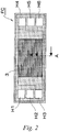
- FIGs. 1 to 3 are views illustrating an embodiment of the fuel cell and the fuel cell stack of the present invention.
- a fuel cell FC illustrated in Figs. 1 and 2 includes a membrane electrode assembly 2 with a frame 1 at the peripheral portion, and separators 3, 3 disposed on both sides of the frame 1 and the membrane electrode assembly 2.
- Fig. 1 is a cross sectional view taken along the line A-A of Fig. 2 .
- the membrane electrode assembly 2 which is generally referred to as an MEA (membrane electrode assembly), is configured such that an electrolyte layer of a solid polymer is sandwiched between a cathode layer (air electrode layer) and an anode layer (fuel electrode layer).
- a cathode layer air electrode layer
- an anode layer fuel electrode layer
- Each of the cathode layer and the anode layer is a laminate of a catalyst layer and a suitable number of gas diffusion layer (not shown in the figures).
- the frame 1 is formed in a rectangular shape with the membrane electrode assembly 2 at the center.
- three manifold holes (not shown) are arranged. The areas from each set of manifold holes to the membrane electrode assembly 2 serve as flow areas of reaction gas.
- each separator 3 is made of stainless steel, and is formed in a rectangular shape corresponding to the frame 1 and the membrane electrode assembly 2.
- Each separator 3 has a corrugated transverse cross-section at least in the center part corresponding to the membrane electrode assembly 2. As illustrated in the figure, the corrugation continues in the longitudinal direction.
- each separator 3 In the center part of each separator 3 corresponding to the membrane electrode assembly 2, the apexes of the corrugation are in contact with the membrane electrode assembly 2 while the bottoms of the corrugations form gas channels for cathode gas (air) and anode gas (hydrogen gas). Further, as illustrated in Fig.2 , each separator 3 has manifold holes H1 to H6 at both ends that are in communication with the respective manifold holes of the frame 1.
- the manifold holes H1 to H3 on one side are holes for supplying the cathode gas (H1), supplying cooling fluid (H2) and discharging the anode gas (H3). These manifold holes are communicated with other manifold holes in the lamination direction to form respective channels.
- the manifold holes H4 to H6 on the other side i.e. on the right side of Fig. 2 , are holes for supplying the anode gas (H4), discharging the cooling fluid (H5) and discharging the cathode gas (H6). These manifold holes are communicated with each other in the lamination direction to form respective channels. The positional relationship between the supply holes and the discharge holes may be suitably changed.
- the fuel cell FC includes gas seals between the rims of the frame 1 and each separator 3 and around the manifold holes H1 to H6. If a plurality of the fuel cells FC are stuck together, the gas seals are provided also between the fuel cells FC, i.e. between adjacent separators 3. In this embodiment, cooling flood flows between adjacent separators 3.
- gas seals hermetically separate flow areas of the cathode gas, the anode gas and the cooling fluid from each other in the gaps between layers. Further, the gas seals around the manifold holes H1 to H6 have openings at suitable positions so that predetermined fluid can flow through the gaps between the layers.
- the fuel cell stack FS includes an end plate 6A on one end in the laminate direction (right end in Fig. 3 ) of a laminate S of the fuel cells FC via a current collector plate 4A and a spacer 5. Further, the fuel cell stack FS includes an end plate 6B on the other end in the lamination direction via a current collector plate 4B. Furthermore, the fuel cell stack FS includes fastening plates 7A, 7B on both faces of the laminate S corresponding to the long sides of the fuel cells FC (upper and lower faces in Fig. 3 ), and reinforcing plates 8A, 8B on both faces corresponding to the short sides.
- each of the fastening plates 7A, 7B and reinforcing plates 8A and 8B is coupled to both end plates 6A and 6B by bolts B.
- the fuel cell stack FS has an integrated structure with a case as illustrated in Fig. 3(B) , in which the laminate S is restrained and pressed in the lamination direction so that a predetermined contact pressure is applied on each fuel cell FS. With this structure, the gas sealing and the electrical conductivity are maintained at high level.
- the fuel cell FC of the present invention which includes the membrane electrode assembly 2 with the frame 1 and the separators 3, 3 as described above, is configured such that: a protrusion and a counterpart groove where the tip of the protrusion is inserted are formed respectively on the portions of the frame 1 and a separator 3 facing each other; and the groove and the protrusion are joined to each other by the adhesive that is injected in the groove.
- This sealing structure is provided along the above-described gas seal that is disposed between the rims of the frame 1 and each separator 3.
- the groove 1G is formed on the frame 1 while the protrusion 3R is formed on the separator 3 in the portions of the frame 1 and the separator 3 that face each other.
- the separator 3 has a recess 3A on the inner face (lower face in Fig. 1 ), and the protrusion 3R is formed on the center of the bottom of the recess 3A.
- the groove 1G of the frame 1 and the recess 3A of the separator 3 have approximately the same width.
- the groove 1G of the frame 1 may be formed together with the frame 1 by injection molding.
- the protrusion 3R and recess 3A of the separator 3 may be formed together with the separator 3 by press working or the like.
- an adhesive 10 is injected in the groove 1G of the frame 1, and the tip of the protrusion 3R of the separator 3 is immersed in the adhesive 10 to join the groove 1G and the protrusion 3R to each other, so that the frame 1 and the separator 3 are joined to each other.
- a room 11 that is hermetically separated by the adhesive 10 is formed between the frame 1 and the separator 3 at least at the side of the protrusion 3R closer to the membrane electrode assembly 2.
- rooms 11, 11 are formed at both sides of the protrusion 3R.
- the fuel cell FC and the fuel cell stack FS with the above-described configuration since the groove 1G and the protrusion 3R are joined to each other by immersing the tip of the protrusion 3R in the adhesive 10 that is injected in the groove 1G, the interface between them is complicated compared to a sealing structure that joins two flat portions to each other. With this configuration, the fuel cell FC can greatly improve the sealing between the frame 1 and the separator 3.
- the sealing of the fuel cell FC is further improved. That is, in the fuel cell FC, if the reaction gas penetrates from the power generating area (area of the membrane electrode assembly 2, indicated by the arrow in Fig. 1 ) into the gap between the frame 1 and the separator 3, the reaction gas flows into the inner room 11. Then, the pressure of the gas acts on the surface of the adhesive 10 to pressurize the adhesive 10, i.e. to cause so-called self-sealing. As a result, the reaction gas is completely prevented from leaking out of the adhesive 10.
- the injection of the adhesive 10 is very easy. Also, since the adhesive 10 would not flow out to the other portions, a low-viscosity adhesive can be used as the adhesive 10. As a result, it becomes possible to improve the productivity or to reduce the cost.
- a fuel cell FC illustrated in Fig. 4 is configured such that: a protrusion 1R is formed on a frame 1 while a groove 3G is formed on a separator 3; and the tip of the protrusion 1R is immersed in an adhesive 10 that is injected in the groove 3G so that the protrusion 1R and the groove 3G are joined to each other. Further, rooms 11 are formed on both sides of the protrusion 1R, which are hermetically separated by the adhesive 10.
- the interface between the two members of this fuel cell FC is complicated compared to a structure that joins two flat portions to each other, which can greatly improve the sealing between the frame 1 and the separator 3.
- the configuration of the fuel cell of the present invention is not limited to those of the above-described embodiments, and details of the configuration may be suitably changed without departing from the scope of the claims.
- the protrusion and the counterpart groove are provided on the frame and one of the separators.
- the same structure may also be formed on the frame and the other of the separators.
Landscapes
- Life Sciences & Earth Sciences (AREA)
- Engineering & Computer Science (AREA)
- Manufacturing & Machinery (AREA)
- Sustainable Development (AREA)
- Sustainable Energy (AREA)
- Chemical & Material Sciences (AREA)
- Chemical Kinetics & Catalysis (AREA)
- Electrochemistry (AREA)
- General Chemical & Material Sciences (AREA)
- Fuel Cell (AREA)
Claims (5)
- Pile à combustible (FC), comprenant :un ensemble d'électrode à membrane (2) avec un cadre (1) au niveau d'une portion périphérique; etun séparateur (3) disposé des deux côtés du cadre (1) et de l'ensemble d'électrode à membrane (2),dans laquelle une protubérance (3R; 1R) et une rainure correspondante (1G; 3G) où une extrémité de la protubérance (3R; 1R) est insérée sont formées respectivement sur des portions du cadre (1) et du séparateur (3) se faisant face l'une à l'autre, et l'extrémité de la protubérance (3R; 1R) est immergée dans une colle (10) qui est injectée dans la rainure (1G; 3G), de sorte que la rainure (1G; 3G) et la protubérance (3R; 1R) soient jointes l'une à l'autre, caractérisée en ce qu'un espace (11), qui est hermétiquement séparé par la colle (10), est formé entre le cadre (1) et le séparateur (3) sur la rainure (1G; 3G) au moins au niveau du côté de la protubérance (3R; 1R) plus proche de l'ensemble d'électrode à membrane (2).
- Pile à combustible (FC) selon la revendication 1, dans laquelle la rainure (1G) est formée sur le cadre (1) et la protubérance (3R) est formée sur le séparateur (3).
- Pile à combustible (FC) selon la revendication 1, dans laquelle la protubérance (1R) est formée sur le cadre (1) et la rainure (3G) est formée sur le séparateur (3).
- Pile à combustible (FC) selon l'une quelconque des revendications 1 à 3, dans laquelle des espaces vides (11), qui sont hermétiquement séparés par la colle (10), sont formés des deux côtés de la protubérance (3R; 1R).
- Empilement de piles à combustible (FS) comprenant une pluralité de piles à combustible (FC) selon l'une quelconque des revendications 1 à 4 qui sont collées les unes aux autres.
Applications Claiming Priority (2)
| Application Number | Priority Date | Filing Date | Title |
|---|---|---|---|
| JP2012063075 | 2012-03-21 | ||
| PCT/JP2013/056790 WO2013141079A1 (fr) | 2012-03-21 | 2013-03-12 | Pile à combustible |
Publications (3)
| Publication Number | Publication Date |
|---|---|
| EP2830130A1 EP2830130A1 (fr) | 2015-01-28 |
| EP2830130A4 EP2830130A4 (fr) | 2015-03-25 |
| EP2830130B1 true EP2830130B1 (fr) | 2017-09-06 |
Family
ID=49222539
Family Applications (1)
| Application Number | Title | Priority Date | Filing Date |
|---|---|---|---|
| EP13764459.7A Not-in-force EP2830130B1 (fr) | 2012-03-21 | 2013-03-12 | Pile à combustible |
Country Status (6)
| Country | Link |
|---|---|
| US (1) | US9318753B2 (fr) |
| EP (1) | EP2830130B1 (fr) |
| JP (1) | JP5773232B2 (fr) |
| CN (1) | CN104205450B (fr) |
| CA (1) | CA2861978C (fr) |
| WO (1) | WO2013141079A1 (fr) |
Families Citing this family (6)
| Publication number | Priority date | Publication date | Assignee | Title |
|---|---|---|---|---|
| JP5979174B2 (ja) | 2014-04-21 | 2016-08-24 | トヨタ自動車株式会社 | 燃料電池および燃料電池スタックの製造方法 |
| JP6123730B2 (ja) * | 2014-04-23 | 2017-05-10 | トヨタ自動車株式会社 | 燃料電池 |
| JP2016004739A (ja) * | 2014-06-19 | 2016-01-12 | トヨタ自動車株式会社 | 燃料電池 |
| CA2985885C (fr) * | 2015-05-13 | 2019-07-30 | Nissan Motor Co., Ltd. | Empilement de piles a combustible |
| JP6870597B2 (ja) * | 2017-12-01 | 2021-05-12 | トヨタ自動車株式会社 | 燃料電池セル |
| JP7196773B2 (ja) * | 2019-05-31 | 2022-12-27 | トヨタ自動車株式会社 | 燃料電池 |
Family Cites Families (9)
| Publication number | Priority date | Publication date | Assignee | Title |
|---|---|---|---|---|
| JP4151314B2 (ja) * | 2001-06-18 | 2008-09-17 | トヨタ自動車株式会社 | 燃料電池 |
| JP4412448B2 (ja) * | 2001-06-20 | 2010-02-10 | Nok株式会社 | 燃料電池用構成部品 |
| JP4815762B2 (ja) * | 2004-07-05 | 2011-11-16 | トヨタ自動車株式会社 | 燃料電池 |
| JP2007035296A (ja) * | 2005-07-22 | 2007-02-08 | Nissan Motor Co Ltd | 電解質膜/電極積層体および燃料電池セル |
| EP1995808B1 (fr) * | 2006-03-08 | 2012-08-22 | Toyota Jidosha Kabushiki Kaisha | Empilement de piles et pile a combustible |
| JP5344273B2 (ja) * | 2006-04-25 | 2013-11-20 | トヨタ自動車株式会社 | 燃料電池およびそのセパレータ |
| JP5412804B2 (ja) | 2008-11-19 | 2014-02-12 | 日産自動車株式会社 | 燃料電池スタック |
| JP5343532B2 (ja) * | 2008-11-27 | 2013-11-13 | 日産自動車株式会社 | 燃料電池及び燃料電池スタック製造方法 |
| JP5077290B2 (ja) * | 2009-05-25 | 2012-11-21 | 日産自動車株式会社 | 燃料電池モジュール及びその製造方法 |
-
2013
- 2013-03-12 EP EP13764459.7A patent/EP2830130B1/fr not_active Not-in-force
- 2013-03-12 CN CN201380014064.0A patent/CN104205450B/zh not_active Expired - Fee Related
- 2013-03-12 JP JP2014506151A patent/JP5773232B2/ja not_active Expired - Fee Related
- 2013-03-12 WO PCT/JP2013/056790 patent/WO2013141079A1/fr active Application Filing
- 2013-03-12 CA CA2861978A patent/CA2861978C/fr active Active
- 2013-03-12 US US14/384,563 patent/US9318753B2/en active Active
Non-Patent Citations (1)
| Title |
|---|
| None * |
Also Published As
| Publication number | Publication date |
|---|---|
| JP5773232B2 (ja) | 2015-09-02 |
| CN104205450B (zh) | 2018-01-26 |
| WO2013141079A1 (fr) | 2013-09-26 |
| US20150086899A1 (en) | 2015-03-26 |
| JPWO2013141079A1 (ja) | 2015-08-03 |
| US9318753B2 (en) | 2016-04-19 |
| EP2830130A1 (fr) | 2015-01-28 |
| CA2861978A1 (fr) | 2013-09-26 |
| CN104205450A (zh) | 2014-12-10 |
| CA2861978C (fr) | 2017-06-20 |
| EP2830130A4 (fr) | 2015-03-25 |
Similar Documents
| Publication | Publication Date | Title |
|---|---|---|
| US8475972B2 (en) | Fuel cell | |
| US9660276B2 (en) | Fuel cell including separator with outer ends placed inward of fluid passages formed in frame | |
| US8137864B2 (en) | Fuel cell formed with metal separators | |
| EP2830130B1 (fr) | Pile à combustible | |
| EP2924787B1 (fr) | Cellule unique de pile à combustible | |
| JP5234446B2 (ja) | 燃料電池スタック用金属セパレータの積層性向上構造 | |
| EP3032626B1 (fr) | Ensemble d'électrodes membranaire, cellule individuelle de pile à combustible et empilement de pile à combustible | |
| US8999592B2 (en) | Fuel cell | |
| KR101416390B1 (ko) | 연료 전지용 금속 분리판, 이를 포함하는 연료 전지 스택 및 이에 적용되는 가스켓 어셈블리 | |
| US20150072265A1 (en) | Fuel cell | |
| US8846264B2 (en) | Fuel cell comprising offset connection channels | |
| US7534518B2 (en) | Cell for solid polymer electrolyte fuel cell with improved gas flow sealing | |
| US20120295176A1 (en) | Fuel cell | |
| JP2012248472A (ja) | 燃料電池用セパレータプレート、燃料電池用セパレータ、燃料電池及び燃料電池用セパレータプレートの製造方法 | |
| CN107534179B (zh) | 燃料电池堆 | |
| JP6241594B2 (ja) | フレーム付き膜電極接合体、燃料電池単セル及び燃料電池スタック | |
| US20140147768A1 (en) | Fuel cell plate and fuel cell | |
| JP7236913B2 (ja) | 燃料電池用分離板組立体およびこれを含む燃料電池スタック | |
| WO2016181522A1 (fr) | Empilement de piles à combustible |
Legal Events
| Date | Code | Title | Description |
|---|---|---|---|
| PUAI | Public reference made under article 153(3) epc to a published international application that has entered the european phase |
Free format text: ORIGINAL CODE: 0009012 |
|
| 17P | Request for examination filed |
Effective date: 20140801 |
|
| AK | Designated contracting states |
Kind code of ref document: A1 Designated state(s): AL AT BE BG CH CY CZ DE DK EE ES FI FR GB GR HR HU IE IS IT LI LT LU LV MC MK MT NL NO PL PT RO RS SE SI SK SM TR |
|
| AX | Request for extension of the european patent |
Extension state: BA ME |
|
| A4 | Supplementary search report drawn up and despatched |
Effective date: 20150223 |
|
| RIC1 | Information provided on ipc code assigned before grant |
Ipc: H01M 8/02 20060101AFI20150217BHEP Ipc: H01M 8/10 20060101ALI20150217BHEP |
|
| DAX | Request for extension of the european patent (deleted) | ||
| GRAP | Despatch of communication of intention to grant a patent |
Free format text: ORIGINAL CODE: EPIDOSNIGR1 |
|
| STAA | Information on the status of an ep patent application or granted ep patent |
Free format text: STATUS: GRANT OF PATENT IS INTENDED |
|
| INTG | Intention to grant announced |
Effective date: 20170412 |
|
| GRAS | Grant fee paid |
Free format text: ORIGINAL CODE: EPIDOSNIGR3 |
|
| GRAJ | Information related to disapproval of communication of intention to grant by the applicant or resumption of examination proceedings by the epo deleted |
Free format text: ORIGINAL CODE: EPIDOSDIGR1 |
|
| GRAL | Information related to payment of fee for publishing/printing deleted |
Free format text: ORIGINAL CODE: EPIDOSDIGR3 |
|
| STAA | Information on the status of an ep patent application or granted ep patent |
Free format text: STATUS: REQUEST FOR EXAMINATION WAS MADE |
|
| INTC | Intention to grant announced (deleted) | ||
| GRAR | Information related to intention to grant a patent recorded |
Free format text: ORIGINAL CODE: EPIDOSNIGR71 |
|
| STAA | Information on the status of an ep patent application or granted ep patent |
Free format text: STATUS: GRANT OF PATENT IS INTENDED |
|
| GRAA | (expected) grant |
Free format text: ORIGINAL CODE: 0009210 |
|
| STAA | Information on the status of an ep patent application or granted ep patent |
Free format text: STATUS: THE PATENT HAS BEEN GRANTED |
|
| INTG | Intention to grant announced |
Effective date: 20170727 |
|
| AK | Designated contracting states |
Kind code of ref document: B1 Designated state(s): AL AT BE BG CH CY CZ DE DK EE ES FI FR GB GR HR HU IE IS IT LI LT LU LV MC MK MT NL NO PL PT RO RS SE SI SK SM TR |
|
| REG | Reference to a national code |
Ref country code: GB Ref legal event code: FG4D |
|
| REG | Reference to a national code |
Ref country code: CH Ref legal event code: EP Ref country code: AT Ref legal event code: REF Ref document number: 926796 Country of ref document: AT Kind code of ref document: T Effective date: 20170915 |
|
| REG | Reference to a national code |
Ref country code: IE Ref legal event code: FG4D |
|
| REG | Reference to a national code |
Ref country code: DE Ref legal event code: R096 Ref document number: 602013026217 Country of ref document: DE |
|
| REG | Reference to a national code |
Ref country code: NL Ref legal event code: MP Effective date: 20170906 |
|
| REG | Reference to a national code |
Ref country code: LT Ref legal event code: MG4D |
|
| PG25 | Lapsed in a contracting state [announced via postgrant information from national office to epo] |
Ref country code: FI Free format text: LAPSE BECAUSE OF FAILURE TO SUBMIT A TRANSLATION OF THE DESCRIPTION OR TO PAY THE FEE WITHIN THE PRESCRIBED TIME-LIMIT Effective date: 20170906 Ref country code: NO Free format text: LAPSE BECAUSE OF FAILURE TO SUBMIT A TRANSLATION OF THE DESCRIPTION OR TO PAY THE FEE WITHIN THE PRESCRIBED TIME-LIMIT Effective date: 20171206 Ref country code: LT Free format text: LAPSE BECAUSE OF FAILURE TO SUBMIT A TRANSLATION OF THE DESCRIPTION OR TO PAY THE FEE WITHIN THE PRESCRIBED TIME-LIMIT Effective date: 20170906 Ref country code: SE Free format text: LAPSE BECAUSE OF FAILURE TO SUBMIT A TRANSLATION OF THE DESCRIPTION OR TO PAY THE FEE WITHIN THE PRESCRIBED TIME-LIMIT Effective date: 20170906 Ref country code: HR Free format text: LAPSE BECAUSE OF FAILURE TO SUBMIT A TRANSLATION OF THE DESCRIPTION OR TO PAY THE FEE WITHIN THE PRESCRIBED TIME-LIMIT Effective date: 20170906 |
|
| REG | Reference to a national code |
Ref country code: AT Ref legal event code: MK05 Ref document number: 926796 Country of ref document: AT Kind code of ref document: T Effective date: 20170906 |
|
| REG | Reference to a national code |
Ref country code: FR Ref legal event code: PLFP Year of fee payment: 6 |
|
| PG25 | Lapsed in a contracting state [announced via postgrant information from national office to epo] |
Ref country code: BG Free format text: LAPSE BECAUSE OF FAILURE TO SUBMIT A TRANSLATION OF THE DESCRIPTION OR TO PAY THE FEE WITHIN THE PRESCRIBED TIME-LIMIT Effective date: 20171206 Ref country code: GR Free format text: LAPSE BECAUSE OF FAILURE TO SUBMIT A TRANSLATION OF THE DESCRIPTION OR TO PAY THE FEE WITHIN THE PRESCRIBED TIME-LIMIT Effective date: 20171207 Ref country code: LV Free format text: LAPSE BECAUSE OF FAILURE TO SUBMIT A TRANSLATION OF THE DESCRIPTION OR TO PAY THE FEE WITHIN THE PRESCRIBED TIME-LIMIT Effective date: 20170906 Ref country code: ES Free format text: LAPSE BECAUSE OF FAILURE TO SUBMIT A TRANSLATION OF THE DESCRIPTION OR TO PAY THE FEE WITHIN THE PRESCRIBED TIME-LIMIT Effective date: 20170906 Ref country code: RS Free format text: LAPSE BECAUSE OF FAILURE TO SUBMIT A TRANSLATION OF THE DESCRIPTION OR TO PAY THE FEE WITHIN THE PRESCRIBED TIME-LIMIT Effective date: 20170906 |
|
| PG25 | Lapsed in a contracting state [announced via postgrant information from national office to epo] |
Ref country code: NL Free format text: LAPSE BECAUSE OF FAILURE TO SUBMIT A TRANSLATION OF THE DESCRIPTION OR TO PAY THE FEE WITHIN THE PRESCRIBED TIME-LIMIT Effective date: 20170906 |
|
| PG25 | Lapsed in a contracting state [announced via postgrant information from national office to epo] |
Ref country code: RO Free format text: LAPSE BECAUSE OF FAILURE TO SUBMIT A TRANSLATION OF THE DESCRIPTION OR TO PAY THE FEE WITHIN THE PRESCRIBED TIME-LIMIT Effective date: 20170906 Ref country code: PL Free format text: LAPSE BECAUSE OF FAILURE TO SUBMIT A TRANSLATION OF THE DESCRIPTION OR TO PAY THE FEE WITHIN THE PRESCRIBED TIME-LIMIT Effective date: 20170906 Ref country code: CZ Free format text: LAPSE BECAUSE OF FAILURE TO SUBMIT A TRANSLATION OF THE DESCRIPTION OR TO PAY THE FEE WITHIN THE PRESCRIBED TIME-LIMIT Effective date: 20170906 |
|
| PG25 | Lapsed in a contracting state [announced via postgrant information from national office to epo] |
Ref country code: AT Free format text: LAPSE BECAUSE OF FAILURE TO SUBMIT A TRANSLATION OF THE DESCRIPTION OR TO PAY THE FEE WITHIN THE PRESCRIBED TIME-LIMIT Effective date: 20170906 Ref country code: EE Free format text: LAPSE BECAUSE OF FAILURE TO SUBMIT A TRANSLATION OF THE DESCRIPTION OR TO PAY THE FEE WITHIN THE PRESCRIBED TIME-LIMIT Effective date: 20170906 Ref country code: IS Free format text: LAPSE BECAUSE OF FAILURE TO SUBMIT A TRANSLATION OF THE DESCRIPTION OR TO PAY THE FEE WITHIN THE PRESCRIBED TIME-LIMIT Effective date: 20180106 Ref country code: SK Free format text: LAPSE BECAUSE OF FAILURE TO SUBMIT A TRANSLATION OF THE DESCRIPTION OR TO PAY THE FEE WITHIN THE PRESCRIBED TIME-LIMIT Effective date: 20170906 Ref country code: IT Free format text: LAPSE BECAUSE OF FAILURE TO SUBMIT A TRANSLATION OF THE DESCRIPTION OR TO PAY THE FEE WITHIN THE PRESCRIBED TIME-LIMIT Effective date: 20170906 Ref country code: SM Free format text: LAPSE BECAUSE OF FAILURE TO SUBMIT A TRANSLATION OF THE DESCRIPTION OR TO PAY THE FEE WITHIN THE PRESCRIBED TIME-LIMIT Effective date: 20170906 |
|
| REG | Reference to a national code |
Ref country code: DE Ref legal event code: R097 Ref document number: 602013026217 Country of ref document: DE |
|
| PLBE | No opposition filed within time limit |
Free format text: ORIGINAL CODE: 0009261 |
|
| STAA | Information on the status of an ep patent application or granted ep patent |
Free format text: STATUS: NO OPPOSITION FILED WITHIN TIME LIMIT |
|
| PG25 | Lapsed in a contracting state [announced via postgrant information from national office to epo] |
Ref country code: DK Free format text: LAPSE BECAUSE OF FAILURE TO SUBMIT A TRANSLATION OF THE DESCRIPTION OR TO PAY THE FEE WITHIN THE PRESCRIBED TIME-LIMIT Effective date: 20170906 |
|
| 26N | No opposition filed |
Effective date: 20180607 |
|
| PG25 | Lapsed in a contracting state [announced via postgrant information from national office to epo] |
Ref country code: SI Free format text: LAPSE BECAUSE OF FAILURE TO SUBMIT A TRANSLATION OF THE DESCRIPTION OR TO PAY THE FEE WITHIN THE PRESCRIBED TIME-LIMIT Effective date: 20170906 |
|
| REG | Reference to a national code |
Ref country code: CH Ref legal event code: PL |
|
| PG25 | Lapsed in a contracting state [announced via postgrant information from national office to epo] |
Ref country code: MC Free format text: LAPSE BECAUSE OF FAILURE TO SUBMIT A TRANSLATION OF THE DESCRIPTION OR TO PAY THE FEE WITHIN THE PRESCRIBED TIME-LIMIT Effective date: 20170906 |
|
| REG | Reference to a national code |
Ref country code: BE Ref legal event code: MM Effective date: 20180331 |
|
| REG | Reference to a national code |
Ref country code: IE Ref legal event code: MM4A |
|
| PG25 | Lapsed in a contracting state [announced via postgrant information from national office to epo] |
Ref country code: LU Free format text: LAPSE BECAUSE OF NON-PAYMENT OF DUE FEES Effective date: 20180312 |
|
| PG25 | Lapsed in a contracting state [announced via postgrant information from national office to epo] |
Ref country code: IE Free format text: LAPSE BECAUSE OF NON-PAYMENT OF DUE FEES Effective date: 20180312 |
|
| PG25 | Lapsed in a contracting state [announced via postgrant information from national office to epo] |
Ref country code: BE Free format text: LAPSE BECAUSE OF NON-PAYMENT OF DUE FEES Effective date: 20180331 Ref country code: LI Free format text: LAPSE BECAUSE OF NON-PAYMENT OF DUE FEES Effective date: 20180331 Ref country code: CH Free format text: LAPSE BECAUSE OF NON-PAYMENT OF DUE FEES Effective date: 20180331 |
|
| PG25 | Lapsed in a contracting state [announced via postgrant information from national office to epo] |
Ref country code: MT Free format text: LAPSE BECAUSE OF NON-PAYMENT OF DUE FEES Effective date: 20180312 |
|
| PG25 | Lapsed in a contracting state [announced via postgrant information from national office to epo] |
Ref country code: TR Free format text: LAPSE BECAUSE OF FAILURE TO SUBMIT A TRANSLATION OF THE DESCRIPTION OR TO PAY THE FEE WITHIN THE PRESCRIBED TIME-LIMIT Effective date: 20170906 |
|
| PG25 | Lapsed in a contracting state [announced via postgrant information from national office to epo] |
Ref country code: HU Free format text: LAPSE BECAUSE OF FAILURE TO SUBMIT A TRANSLATION OF THE DESCRIPTION OR TO PAY THE FEE WITHIN THE PRESCRIBED TIME-LIMIT; INVALID AB INITIO Effective date: 20130312 Ref country code: PT Free format text: LAPSE BECAUSE OF FAILURE TO SUBMIT A TRANSLATION OF THE DESCRIPTION OR TO PAY THE FEE WITHIN THE PRESCRIBED TIME-LIMIT Effective date: 20170906 |
|
| PG25 | Lapsed in a contracting state [announced via postgrant information from national office to epo] |
Ref country code: MK Free format text: LAPSE BECAUSE OF NON-PAYMENT OF DUE FEES Effective date: 20170906 Ref country code: CY Free format text: LAPSE BECAUSE OF FAILURE TO SUBMIT A TRANSLATION OF THE DESCRIPTION OR TO PAY THE FEE WITHIN THE PRESCRIBED TIME-LIMIT Effective date: 20170906 |
|
| PG25 | Lapsed in a contracting state [announced via postgrant information from national office to epo] |
Ref country code: AL Free format text: LAPSE BECAUSE OF FAILURE TO SUBMIT A TRANSLATION OF THE DESCRIPTION OR TO PAY THE FEE WITHIN THE PRESCRIBED TIME-LIMIT Effective date: 20170906 |
|
| PGFP | Annual fee paid to national office [announced via postgrant information from national office to epo] |
Ref country code: GB Payment date: 20220120 Year of fee payment: 10 Ref country code: DE Payment date: 20220118 Year of fee payment: 10 |
|
| PGFP | Annual fee paid to national office [announced via postgrant information from national office to epo] |
Ref country code: FR Payment date: 20220118 Year of fee payment: 10 |
|
| REG | Reference to a national code |
Ref country code: DE Ref legal event code: R119 Ref document number: 602013026217 Country of ref document: DE |
|
| GBPC | Gb: european patent ceased through non-payment of renewal fee |
Effective date: 20230312 |
|
| PG25 | Lapsed in a contracting state [announced via postgrant information from national office to epo] |
Ref country code: GB Free format text: LAPSE BECAUSE OF NON-PAYMENT OF DUE FEES Effective date: 20230312 |
|
| PG25 | Lapsed in a contracting state [announced via postgrant information from national office to epo] |
Ref country code: GB Free format text: LAPSE BECAUSE OF NON-PAYMENT OF DUE FEES Effective date: 20230312 Ref country code: FR Free format text: LAPSE BECAUSE OF NON-PAYMENT OF DUE FEES Effective date: 20230331 Ref country code: DE Free format text: LAPSE BECAUSE OF NON-PAYMENT OF DUE FEES Effective date: 20231003 |