EP2830124B1 - Battery module - Google Patents
Battery module Download PDFInfo
- Publication number
- EP2830124B1 EP2830124B1 EP14178306.8A EP14178306A EP2830124B1 EP 2830124 B1 EP2830124 B1 EP 2830124B1 EP 14178306 A EP14178306 A EP 14178306A EP 2830124 B1 EP2830124 B1 EP 2830124B1
- Authority
- EP
- European Patent Office
- Prior art keywords
- battery module
- battery
- degassing device
- barriers
- barrier
- Prior art date
- Legal status (The legal status is an assumption and is not a legal conclusion. Google has not performed a legal analysis and makes no representation as to the accuracy of the status listed.)
- Active
Links
- 230000004888 barrier function Effects 0.000 claims description 119
- 238000007872 degassing Methods 0.000 claims description 64
- 230000003014 reinforcing effect Effects 0.000 claims description 45
- 239000000463 material Substances 0.000 claims description 8
- 230000002787 reinforcement Effects 0.000 description 9
- 230000008878 coupling Effects 0.000 description 8
- 238000010168 coupling process Methods 0.000 description 8
- 238000005859 coupling reaction Methods 0.000 description 8
- 239000007769 metal material Substances 0.000 description 6
- 238000005192 partition Methods 0.000 description 2
- 230000002159 abnormal effect Effects 0.000 description 1
- 230000001413 cellular effect Effects 0.000 description 1
- 238000007599 discharging Methods 0.000 description 1
- 230000005611 electricity Effects 0.000 description 1
- 230000005484 gravity Effects 0.000 description 1
- 230000000284 resting effect Effects 0.000 description 1
- 229910001220 stainless steel Inorganic materials 0.000 description 1
- 239000010935 stainless steel Substances 0.000 description 1
- 229920003002 synthetic resin Polymers 0.000 description 1
- 239000000057 synthetic resin Substances 0.000 description 1
Images


Classifications
-
- H—ELECTRICITY
- H01—ELECTRIC ELEMENTS
- H01M—PROCESSES OR MEANS, e.g. BATTERIES, FOR THE DIRECT CONVERSION OF CHEMICAL ENERGY INTO ELECTRICAL ENERGY
- H01M50/00—Constructional details or processes of manufacture of the non-active parts of electrochemical cells other than fuel cells, e.g. hybrid cells
- H01M50/20—Mountings; Secondary casings or frames; Racks, modules or packs; Suspension devices; Shock absorbers; Transport or carrying devices; Holders
-
- H—ELECTRICITY
- H01—ELECTRIC ELEMENTS
- H01M—PROCESSES OR MEANS, e.g. BATTERIES, FOR THE DIRECT CONVERSION OF CHEMICAL ENERGY INTO ELECTRICAL ENERGY
- H01M10/00—Secondary cells; Manufacture thereof
- H01M10/04—Construction or manufacture in general
- H01M10/0486—Frames for plates or membranes
-
- H—ELECTRICITY
- H01—ELECTRIC ELEMENTS
- H01M—PROCESSES OR MEANS, e.g. BATTERIES, FOR THE DIRECT CONVERSION OF CHEMICAL ENERGY INTO ELECTRICAL ENERGY
- H01M10/00—Secondary cells; Manufacture thereof
- H01M10/20—Semi-lead accumulators, i.e. accumulators in which only one electrode contains lead
-
- H—ELECTRICITY
- H01—ELECTRIC ELEMENTS
- H01M—PROCESSES OR MEANS, e.g. BATTERIES, FOR THE DIRECT CONVERSION OF CHEMICAL ENERGY INTO ELECTRICAL ENERGY
- H01M50/00—Constructional details or processes of manufacture of the non-active parts of electrochemical cells other than fuel cells, e.g. hybrid cells
- H01M50/20—Mountings; Secondary casings or frames; Racks, modules or packs; Suspension devices; Shock absorbers; Transport or carrying devices; Holders
- H01M50/204—Racks, modules or packs for multiple batteries or multiple cells
- H01M50/207—Racks, modules or packs for multiple batteries or multiple cells characterised by their shape
- H01M50/209—Racks, modules or packs for multiple batteries or multiple cells characterised by their shape adapted for prismatic or rectangular cells
-
- H—ELECTRICITY
- H01—ELECTRIC ELEMENTS
- H01M—PROCESSES OR MEANS, e.g. BATTERIES, FOR THE DIRECT CONVERSION OF CHEMICAL ENERGY INTO ELECTRICAL ENERGY
- H01M50/00—Constructional details or processes of manufacture of the non-active parts of electrochemical cells other than fuel cells, e.g. hybrid cells
- H01M50/20—Mountings; Secondary casings or frames; Racks, modules or packs; Suspension devices; Shock absorbers; Transport or carrying devices; Holders
- H01M50/218—Mountings; Secondary casings or frames; Racks, modules or packs; Suspension devices; Shock absorbers; Transport or carrying devices; Holders characterised by the material
- H01M50/22—Mountings; Secondary casings or frames; Racks, modules or packs; Suspension devices; Shock absorbers; Transport or carrying devices; Holders characterised by the material of the casings or racks
- H01M50/222—Inorganic material
- H01M50/224—Metals
-
- H—ELECTRICITY
- H01—ELECTRIC ELEMENTS
- H01M—PROCESSES OR MEANS, e.g. BATTERIES, FOR THE DIRECT CONVERSION OF CHEMICAL ENERGY INTO ELECTRICAL ENERGY
- H01M50/00—Constructional details or processes of manufacture of the non-active parts of electrochemical cells other than fuel cells, e.g. hybrid cells
- H01M50/20—Mountings; Secondary casings or frames; Racks, modules or packs; Suspension devices; Shock absorbers; Transport or carrying devices; Holders
- H01M50/233—Mountings; Secondary casings or frames; Racks, modules or packs; Suspension devices; Shock absorbers; Transport or carrying devices; Holders characterised by physical properties of casings or racks, e.g. dimensions
- H01M50/242—Mountings; Secondary casings or frames; Racks, modules or packs; Suspension devices; Shock absorbers; Transport or carrying devices; Holders characterised by physical properties of casings or racks, e.g. dimensions adapted for protecting batteries against vibrations, collision impact or swelling
-
- H—ELECTRICITY
- H01—ELECTRIC ELEMENTS
- H01M—PROCESSES OR MEANS, e.g. BATTERIES, FOR THE DIRECT CONVERSION OF CHEMICAL ENERGY INTO ELECTRICAL ENERGY
- H01M50/00—Constructional details or processes of manufacture of the non-active parts of electrochemical cells other than fuel cells, e.g. hybrid cells
- H01M50/20—Mountings; Secondary casings or frames; Racks, modules or packs; Suspension devices; Shock absorbers; Transport or carrying devices; Holders
- H01M50/262—Mountings; Secondary casings or frames; Racks, modules or packs; Suspension devices; Shock absorbers; Transport or carrying devices; Holders with fastening means, e.g. locks
-
- H—ELECTRICITY
- H01—ELECTRIC ELEMENTS
- H01M—PROCESSES OR MEANS, e.g. BATTERIES, FOR THE DIRECT CONVERSION OF CHEMICAL ENERGY INTO ELECTRICAL ENERGY
- H01M50/00—Constructional details or processes of manufacture of the non-active parts of electrochemical cells other than fuel cells, e.g. hybrid cells
- H01M50/20—Mountings; Secondary casings or frames; Racks, modules or packs; Suspension devices; Shock absorbers; Transport or carrying devices; Holders
- H01M50/289—Mountings; Secondary casings or frames; Racks, modules or packs; Suspension devices; Shock absorbers; Transport or carrying devices; Holders characterised by spacing elements or positioning means within frames, racks or packs
- H01M50/291—Mountings; Secondary casings or frames; Racks, modules or packs; Suspension devices; Shock absorbers; Transport or carrying devices; Holders characterised by spacing elements or positioning means within frames, racks or packs characterised by their shape
-
- H—ELECTRICITY
- H01—ELECTRIC ELEMENTS
- H01M—PROCESSES OR MEANS, e.g. BATTERIES, FOR THE DIRECT CONVERSION OF CHEMICAL ENERGY INTO ELECTRICAL ENERGY
- H01M50/00—Constructional details or processes of manufacture of the non-active parts of electrochemical cells other than fuel cells, e.g. hybrid cells
- H01M50/30—Arrangements for facilitating escape of gases
- H01M50/35—Gas exhaust passages comprising elongated, tortuous or labyrinth-shaped exhaust passages
- H01M50/367—Internal gas exhaust passages forming part of the battery cover or case; Double cover vent systems
-
- Y—GENERAL TAGGING OF NEW TECHNOLOGICAL DEVELOPMENTS; GENERAL TAGGING OF CROSS-SECTIONAL TECHNOLOGIES SPANNING OVER SEVERAL SECTIONS OF THE IPC; TECHNICAL SUBJECTS COVERED BY FORMER USPC CROSS-REFERENCE ART COLLECTIONS [XRACs] AND DIGESTS
- Y02—TECHNOLOGIES OR APPLICATIONS FOR MITIGATION OR ADAPTATION AGAINST CLIMATE CHANGE
- Y02E—REDUCTION OF GREENHOUSE GAS [GHG] EMISSIONS, RELATED TO ENERGY GENERATION, TRANSMISSION OR DISTRIBUTION
- Y02E60/00—Enabling technologies; Technologies with a potential or indirect contribution to GHG emissions mitigation
- Y02E60/10—Energy storage using batteries
-
- Y—GENERAL TAGGING OF NEW TECHNOLOGICAL DEVELOPMENTS; GENERAL TAGGING OF CROSS-SECTIONAL TECHNOLOGIES SPANNING OVER SEVERAL SECTIONS OF THE IPC; TECHNICAL SUBJECTS COVERED BY FORMER USPC CROSS-REFERENCE ART COLLECTIONS [XRACs] AND DIGESTS
- Y02—TECHNOLOGIES OR APPLICATIONS FOR MITIGATION OR ADAPTATION AGAINST CLIMATE CHANGE
- Y02P—CLIMATE CHANGE MITIGATION TECHNOLOGIES IN THE PRODUCTION OR PROCESSING OF GOODS
- Y02P70/00—Climate change mitigation technologies in the production process for final industrial or consumer products
- Y02P70/50—Manufacturing or production processes characterised by the final manufactured product
Definitions
- the present invention relates to a battery module with a battery array, a pair of end blocks, a pair of side frames and a degassing device, the battery array comprising a plurality of battery cells arranged one after the other in a first direction, and a plurality of barriers, each of which being arranged between and holding two of the battery cells that are consecutively arranged in the first direction, the battery array being arranged between the end blocks in and between the side frames transversely to the first direction, the side frames being fixed to the end blocks, and the degassing device spanning the end blocks and the battery array and providing a passage for directing gas vented from the battery cells away from the battery module, wherein the degassing device is rigidly supporting the battery array, and more particularly, to a battery module available for an electric vehicle and a hybrid vehicle, etc.
- secondary batteries can be reused by discharging and recharging, unlike primary batteries, which are not rechargeable.
- the secondary batteries are used as energy sources for mobile devices, electric vehicles, hybrid vehicles, electric bicycles, and uninterrruptible power supplies.
- the secondary batteries may be used in a single battery type or a battery module type composed of a plurality of batteries connected in one unit, in accordance with various available external devices. Battery modules are described e.g. in JP 2010 251019 A , JP 2009 170258 A , US 2013/0034755 A1 and EP 2 381 507 A1 .
- the battery modules are used by connecting a required number of batteries in parallel or series in accordance with output and capacity.
- the invention provides a battery module of the above mentioned type and having an improved structural stability.
- a battery module is achieved according to the invention in that the barriers have protruding portions respectively formed at both ends of an upper portion of the barriers, the protruding portions protruding in the first direction, and receiving portions that correspond to the shape of the protruding portions, each of the receiving portions being formed opposite of a respective one of the protruding portions, wherein one end block of the pair of end blocks has a protruding portion that is insertable into the receiving portion of the barrier adjacent to the one end block, and the other end block of the pair of end blocks has a receiving portion in which the protruding portion of the barrier adjacent to the other end block is receivable.
- the degassing device improves mechanical stability of the battery module without necessitating additional reinforcement structures. Hence, the weight and the volume of the battery module are not affected.
- the degassing device may be formed as a beam to receive and to transmit forces and the hold the battery array at least partly. Furthermore, forces, in particular perpendicular to the first direction, can be transmitted from one of the barriers to another one of the barriers, for instance from or to the reinforcement barrier, by the fastening member.
- the degassing device can be fixed to at least one of the barriers.
- forces can be transmitted between the degassing device and the barrier, thereby further improving stability of the battery module.
- the degassing device may is fixed to at least one of the barriers by a mounting element.
- the mounting element can be easily installed.
- the degassing device may rest against at least one of the end blocks and / or may be fixed to at least one of the end blocks. By resting against one or even both of the end blocks, forces transmitted from the barrier to the degassing device can be transferred to the end block. In case the degassing device is fixed to the end block or to both end blocks, the position of the degassing device relative to the end block is secured, facilitating and easy handling of the battery module and further improving stability.
- the battery module can comprise a reinforcing barrier that is added to or replaces one of the barriers.
- the reinforcing barrier to which the degassing device is fixed.
- the reinforcing barrier can furthermore be coupled to at least one of the side frames. Due to the reinforcement barrier, forces in different direction can be transmitted, thereby further improving stability.
- At least one fastening opening can extend through the reinforcing barrier perpendicular to the first direction. Via the fastening opening, the degassing device can be coupled to the reinforcement barrier.
- a maximum thickness of the reinforcing barrier along the first direction is preferably greater than a maximum thickness of at least one of the barriers.
- the reinforcement can be mechanically more stable and in particular in case it comprises the fastening opening, the mechanical stability still suffices for receiving forces from the degassing device and for directly holding at least one or even two of the battery cells.
- the reinforcing barrier is preferably arranged in a central region of the battery array. Thus, a transfer of forces towards the reinforcement barrier can be balanced.
- the battery module can comprise at least one fastening rod that extends through the fastening opening and that affixes the degassing device to the reinforcing barrier.
- the fastening rod can be a bolt. It provides for an easy, stable and probably even detachable connection between the degassing device and the reinforcement barrier.
- the barriers may comprise at least one fastening member that is adapted to captively fix one of the barriers to another one of the barriers, e.g. by a force fit.
- the barriers may be attached to each other and to the end blocks non-relocatabley with respect to the battery cells and perpendicular to the first direction.
- forces, in particular perpendicular to the first direction can be transmitted from one of the barriers to another one of the barriers, for instance from or to the reinforcement barrier, by the fastening member.
- the fastening member is preferably adapted to captively fixe one of the barriers to another one of the barriers by a force fit. Hence, the barriers can be easily affixes to each other.
- the side frames may each have a C-shaped cross-section perpendicular to the first direction.
- the side frames preferably each comprise two holding plates and one side plate interconnecting the two holding plates, wherein the side frames each encompass an edge region of the battery array. Therefore, also the side frames can contribute to the mechanical stability of the battery module and can carry the battery cells, for instance via the barriers.
- the pair of end blocks, the pair of side frames and the degassing device may form a self-supporting structure for holding the battery array.
- a self-supporting structure itself keeps its form under influence of gravity. Furthermore, it can keep its form even if weight, for instance from the battery cells, is added. Moreover, it can preferably be handled as one piece.
- the self-supporting structure not only improves stability, but furthermore provides for an easily to handle and to assemble battery module.
- a surface of the reinforcing barrier that faces one of the side frames can comprise a material that is similar to a material of the adjacent side frame.
- the reinforcement barrier can be easily attached to the side frames, e.g. by a material fit.
- the surface is preferably welded to the adjacent side frame, thereby providing a very stable material fit.
- the embodiments provide a battery module having a coupling structure, i.e. the degassing device, between barriers, which improves the structural rigidity of the battery module.
- the battery array includes the plurality of battery cells arranged in the first direction, and the plurality of barriers respectively interposed between the battery cells.
- the pair of end blocks are respectively provided at outsides of the outermost battery cells of the battery array.
- the pair of side frames are respectively at both sides of the battery array along the first direction, and each side frame is fixed to the end blocks.
- the degassing device preferably has inlets formed at a lower portion thereof. The inlets allow gas exhausted from each battery cell through a vent element of the battery cell to flow through the degassing device.
- the degassing device provides a flow path through which the gas vented from the battery cells may flow.
- the degassing device may be formed of a metal material, and each end of the degassing device may be fixed to one of the end blocks, thereby improving the structural rigidity of the battery module.
- Each barrier may have a protruding portion that protrudes in the first direction, and a receiving portion, in which the protruding portion can be inserted and which can be formed in the opposite direction to the first direction, so that adjacent barriers can be coupled to each other.
- the protruding portion and the receiving portion are preferably integrally provided by the fastening member.
- Any one of the pair of end blocks may have a protruding portion that can be inserted into the receiving portion of the barrier adjacent to the one end block, and the other of the pair of end blocks may have a receiving portion in which the protruding portion of the barrier adjacent to the other end block can be received.
- the battery module may further include the mounting element, which may for instance be formed as a band member, a clamp or a bracket configured to allow the degassing portion to be fixed to the pair of end blocks.
- a central portion of the mounting element may be provided to surround an outer circumferential surface of the degassing portion, and both end portions of the mounting element may be fixed to the respective end blocks through fastening elements, e.g. bolts.
- the battery module may further include the reinforcing barrier which is substituted for any one of the barriers or added to any one of the barriers.
- the reinforcing barrier may be fixed to the pair of side frames and the degassing device, thereby improving the structural rigidity of the battery module.
- the mounting element may allow the degassing portion to be fixed to the reinforcing barrier.
- the central portion of the mounting element may be provided to surround the outer circumferential surface of the degassing device at least sectionwise, and both the end portions of the mounting element may be fixed to the reinforcing barrier via the fastening elements.
- Upper and lower end portions of the side frame may respectively bent toward upper and lower surfaces of the battery array.
- the upper and lower portions may extend along the upper and lower surfaces of the battery array and e.g. of the battery cells.
- a buffer member may be provided between the upper end portion of the side frame and the upper surface of the battery array or cell.
- the outer frame structure of the battery module is preferably formed using the side frames, the end blocks and the degassing device made of a metal material, so that it is possible to improve the structural rigidity of the entire battery module.
- the buffer member may be provided between the side frame and the battery array, so that although the battery module is used for an electric vehicle or hybrid vehicle, it is possible to prevent external vibration from being directly transferred to the battery cells.
- the reinforcing barrier can be fixed to the degassing device that is preferably made of the metal material, so that it is possible to maintain the structural stability of the battery module even when the entire length of the battery module increases, e.g. if more battery cells are to be arranged in the array.
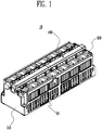
- FIG. 1 is a perspective view showing the battery module according to the embodiment of the present invention.
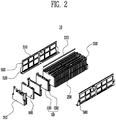
- FIG. 2 is an exploded perspective view showing the battery module according to the embodiment of the present invention.
- the battery module 10 has an outer frame structure in which a battery array 50 can be regularly fixed.
- the outer frame structure includes side frames 500, end blocks 310 and 320, and a reinforcing barrier 250.
- the battery array 50 is formed so that a plurality of battery cells 100 and barriers 200 are arranged in one direction.
- a degassing device 400 configured to guide gas toward the outside of the battery module 10 is provided at an upper portion of the battery array 50. Here, the gas may be exhausted from the battery cells 100 of the battery array 50. The configuration and fastening of the degassing device 400 will be described in detail later.
- the pair of end blocks 310 and 320 are respectively provided at both end portions of the barrier array 50, i.e., outsides of the outermost battery cells 100.
- the side frames 500 are respectively provided both sides of the battery cells 100 and the barriers 200.
- the frames 500 and the end blocks 310 and 320 may be firmly fixed through structural coupling or screw fastening.
- upper and lower portions of the side frame 500 may be bent to directly/indirectly support upper and lower portions of the battery array 50.
- the battery module 10 may have the reinforcing barrier 250 provided at a central portion or the like of the battery module 10 in order to improve the structural stability of the battery module 10.
- an upper holding plate 510 e.g. an upper bent surface and a lower holding plate 520, e.g. a lower bent surface may be respectively formed at upper and lower end portions of the side frame 500.
- Each of the upper and lower holding plates 510 and 520 may be formed in a shape bent toward the battery array 50.
- a buffer member 333 may be provided between the battery array 50 and the upper holding plate 510.
- the buffer member 333 absorbs impact between the upper holding plate 510 and the battery array 50, so that it is possible to prevent external vibration or the like from being directly transferred to the battery cell 110.
- FIG. 3 is an exploded perspective view showing the barrier and the battery cell according to the embodiment of the present invention.
- the battery cell 100 has electrical terminals 120 exposed at an upper portion thereof, and a vent element 110 provided between the terminals 120.
- the vent element 110 is a portion through which internal gas caused by an abnormal operation of the battery cell 100 is exhausted to the outside of the battery cell 100.
- the barrier 200 may be formed as a partition wall which allows the battery cell 100 to be spaced apart from the other battery cells.
- the barrier 200 may serve as a structure which maintains an exact interval between the battery cells 10 or press the battery cells 100.
- the barrier 200 according to this embodiment has a battery mounting portion 210.
- the battery cell 100 is mounted on the battery mounting portion 210.
- the battery cell 100 and the barrier 200 are repetitively arranged in a state in which the battery cell 100 and the barrier 200 are coupled as described above.
- FIG. 4 is a perspective view showing the reinforcing barrier according to the embodiment of the present invention.
- the shape of the reinforcing barrier 250 is similar to that of the barrier described above. That is, the reinforcing barrier 250 is entirely formed into a partition wall structure, and a mounting portion 260 is formed at a lower portion of the reinforcing barrier 250 so that the battery cell can be mounted thereon.
- the reinforcing barrier 250 is a portion which performs not only a simple function of allowing the battery cells to be spaced apart from each other and maintain the interval between the battery cells but also a function of forming an outer frame structure, i.e., a rigidity structure of the battery module by being fastened to other portions.
- a fastening opening 270 through which the reinforcing barrier 250 is fastened to other portions is formed in the reinforcing barrier 250.
- the fastening portion 270 allows the degassing device to be fixed using a mounting element described later. This will be described in detail later.
- the reinforcing barrier 250 may have various types of fastening structures so that the side frame is fastened to a surface 280 of the reinforcing barrier 250, which faces the side frame.
- a bolt receiving hole corresponding to a bolt is formed in the surface 280 of the reinforcing barrier 250, so that the surface 280 can be fastened to the side frame.
- the reinforcing barrier 250 is a portion which increases the rigidity of the battery module, and therefore, the thickness of the reinforcing barrier 250 is preferably further increased as compared with other barriers.
- the side frame is a portion on which most of the entire load of the battery module is concentrated.
- the side frame is formed using a material such as stainless steel, which has a certain rigidity or more.
- the reinforcing barrier 250 performs a function of allowing the battery cells to be spaced apart and insulated from each other. Therefore, the reinforcing barrier 250 is preferably formed of a synthetic resin material.
- FIG. 5 is an exploded perspective view showing the coupling structure between the end block and the barriers according to the embodiment of the present invention.
- the end block 310 is provided at the outermost portion of the battery module.
- the battery module has a coupling structure in which the end block 310 and the barrier 200 are coupled to each other.
- the barrier 200 according to this embodiment has protruding portions 230 respectively formed at both ends of the upper portion thereof.
- the protruding portion 230 is protruded in the arrangement direction of the battery cells.
- a receiving portion 235 corresponding to the shape of the protruding portion 230 is formed at the opposite side of the protruding portion 230.
- the barrier 200 has the protruding portion 230 protruded in one direction and a receiving portion 235 formed at the other side to receive the protruding portion 230, so that the protruding portion 230 of a specific barrier 200 is coupled to the receiving portion 235 of another barrier 200 adjacent to the specific barrier 200.
- one end block 310 has only protruding portions 330 protruded toward the barrier 200, and the other end block (not shown) has only receiving portions 335 corresponding to the respective protruding portions 330. Accordingly, the end block 310 and the barriers 200 are coupled to each other through the coupling structure described above.
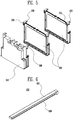
- FIG. 6 is a perspective view showing the degassing device according to the embodiment of the present invention.
- FIG. 7 is a bottom perspective view showing the degassing device according to the present invention.
- the degassing device 400 is formed in the shape of a hollow rectangular parallelepiped. That is, inlets 420 through which the gas exhausted to the outside of the battery cell through the vent element described above is flowed in the degassing device 400 are formed on a bottom surface of the degassing device 400. A flow path through which the gas flowed in the degassing 410 through the inlets 420 is guided to the outside of the battery module is formed inside a body 410 of the degassing device 400.
- FIG. 8 is a longitudinal sectional view showing the reinforcing barrier according to the embodiment of the present invention.
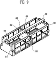
- FIG. 9 is a perspective view showing the rigidity structure including the degassing device according to the embodiment of the present invention.
- FIG. 10 is a longitudinal sectional view showing a state in which a central portion of the rigidity structure of FIG. 9 is cut away.
- the reinforcing barrier 250 has the fastening opening 270 passing through the top and bottom thereof.
- the pair of side frames 500 and the pair of end blocks 310 and 320 are fastened or fixed to each other, so as to form the outer frame structure in terms of the structure of the battery module.
- both end portions of the reinforcing barrier 250 are respectively fixed to central portions of the side frames 500.
- the reinforcing barrier 250 is fixed to the degassing device 400 through a mounting element 450.
- the degassing device 400 is also fixed to the end blocks 310 and 320 through the mounting element 450.
- a central portion of the mounting element 450 is provided to surround an outer circumferential surface of the degassing device 400, and both end portions of the mounting element 450 are fixed to the fastening opening 270 by bolts as shown in FIG. 10 .
- the degassing device 400 according to this embodiment is formed of a metal material.
- components related to degassing are simply limited to the function of allowing internal gas to be exhausted to the outside of the battery module.
- the degassing device 400 is formed of the metal material, and the coupling structure between the degassing device 400 and the rigidity structure is introduced to the battery module, so that it is possible to increase the structural rigidity of the entire battery module.
- the degassing device 400 made of the metal material is connected to the reinforcing barrier 250, the side frame 500 and the like, so that it is possible to the rigidity structure from distorted at the central portion of the degassing device 400 or being sunk downward by the weight of the battery cells.
Landscapes
- Chemical & Material Sciences (AREA)
- Chemical Kinetics & Catalysis (AREA)
- Electrochemistry (AREA)
- General Chemical & Material Sciences (AREA)
- Inorganic Chemistry (AREA)
- Engineering & Computer Science (AREA)
- Manufacturing & Machinery (AREA)
- Battery Mounting, Suspending (AREA)
Applications Claiming Priority (2)
| Application Number | Priority Date | Filing Date | Title |
|---|---|---|---|
| US201361858834P | 2013-07-26 | 2013-07-26 | |
| US14/226,390 US9553289B2 (en) | 2013-07-26 | 2014-03-26 | Battery module |
Publications (2)
| Publication Number | Publication Date |
|---|---|
| EP2830124A1 EP2830124A1 (en) | 2015-01-28 |
| EP2830124B1 true EP2830124B1 (en) | 2020-05-06 |
Family
ID=51292797
Family Applications (1)
| Application Number | Title | Priority Date | Filing Date |
|---|---|---|---|
| EP14178306.8A Active EP2830124B1 (en) | 2013-07-26 | 2014-07-24 | Battery module |
Country Status (5)
| Country | Link |
|---|---|
| US (1) | US9553289B2 (zh) |
| EP (1) | EP2830124B1 (zh) |
| KR (1) | KR102257681B1 (zh) |
| CN (1) | CN104347833B (zh) |
| IN (1) | IN2014DE01970A (zh) |
Families Citing this family (15)
| Publication number | Priority date | Publication date | Assignee | Title |
|---|---|---|---|---|
| KR102222888B1 (ko) | 2014-04-09 | 2021-03-04 | 삼성에스디아이 주식회사 | 배터리모듈 |
| US10199621B2 (en) * | 2015-06-11 | 2019-02-05 | Ford Global Technologies, Llc | Battery cell spacer for establishing dielectric barriers within a battery assembly |
| JP6685761B2 (ja) * | 2016-02-19 | 2020-04-22 | 株式会社Gsユアサ | 蓄電装置 |
| CN105742539B (zh) | 2016-04-21 | 2019-04-05 | 宁德时代新能源科技股份有限公司 | 一种电芯模组 |
| CN108075067A (zh) * | 2016-11-18 | 2018-05-25 | 比亚迪股份有限公司 | 电池包 |
| CN110996737A (zh) | 2017-06-19 | 2020-04-10 | 创科(澳门离岸商业服务)有限公司 | 表面清洁设备 |
| KR102106448B1 (ko) * | 2017-12-11 | 2020-05-04 | 삼성에스디아이 주식회사 | 배터리 팩 |
| KR102330377B1 (ko) * | 2018-10-12 | 2021-11-22 | 주식회사 엘지에너지솔루션 | 배터리 모듈, 이러한 배터리 모듈을 포함하는 배터리 랙 및 이러한 배터리 랙을 포함하는 전력 저장 장치 |
| CN210092179U (zh) | 2019-07-26 | 2020-02-18 | 宁德时代新能源科技股份有限公司 | 电池模组、电池包和车辆 |
| JP7275168B2 (ja) * | 2019-08-09 | 2023-05-17 | 欣旺達電動汽車電池有限公司 | バッテリーモジュール |
| CN112331981B (zh) * | 2019-10-15 | 2021-09-17 | 宁德时代新能源科技股份有限公司 | 电池包和车辆 |
| CN111403657B (zh) * | 2020-03-31 | 2022-04-01 | 重庆长安新能源汽车科技有限公司 | 一种电池热失控气体排放装置、电池模组及汽车 |
| KR20210122509A (ko) * | 2020-04-01 | 2021-10-12 | 주식회사 엘지에너지솔루션 | 전지 모듈 및 이를 포함하는 전지 팩 |
| JP7378905B2 (ja) | 2021-05-19 | 2023-11-14 | プライムアースEvエナジー株式会社 | 電池モジュール |
| KR20230052033A (ko) * | 2021-10-12 | 2023-04-19 | 엘지전자 주식회사 | 에너지저장장치 |
Citations (2)
| Publication number | Priority date | Publication date | Assignee | Title |
|---|---|---|---|---|
| US20120040234A1 (en) * | 2009-05-15 | 2012-02-16 | Calsonic Kansei Corporation | Laminated battery and manufacturing method thereof |
| US20130034755A1 (en) * | 2011-08-02 | 2013-02-07 | Myung-Chul Kim | Battery module |
Family Cites Families (15)
| Publication number | Priority date | Publication date | Assignee | Title |
|---|---|---|---|---|
| US20030049521A1 (en) * | 2001-09-11 | 2003-03-13 | Japan Storage Battery Co., Ltd. | Lead acid battery |
| JP2009135088A (ja) * | 2007-10-29 | 2009-06-18 | Panasonic Corp | 電池パックおよび電池搭載機器 |
| JP5183171B2 (ja) * | 2007-11-28 | 2013-04-17 | 三洋電機株式会社 | バッテリシステム |
| JP5334420B2 (ja) | 2008-01-16 | 2013-11-06 | 三洋電機株式会社 | バッテリシステム |
| JP2010251019A (ja) | 2009-04-13 | 2010-11-04 | Sanyo Electric Co Ltd | バッテリシステム |
| KR101700254B1 (ko) * | 2009-05-14 | 2017-01-26 | 가부시키가이샤 지에스 유아사 | 집합 전지 |
| KR101127602B1 (ko) | 2009-10-22 | 2012-03-22 | 에스비리모티브 주식회사 | 배터리 유닛 및 이를 구비하는 배터리 팩 |
| US9147916B2 (en) * | 2010-04-17 | 2015-09-29 | Lg Chem, Ltd. | Battery cell assemblies |
| US8999557B2 (en) * | 2010-04-21 | 2015-04-07 | Samsung Sdi Co., Ltd. | Battery pack with elastic frame |
| DE102010046529A1 (de) * | 2010-09-24 | 2012-03-29 | Volkswagen Ag | Rahmensystem für Batteriezellen sowie Batteriemodul |
| US8748021B2 (en) * | 2010-10-19 | 2014-06-10 | Samsung Sdi Co., Ltd. | Battery module |
| US9196883B2 (en) | 2010-11-04 | 2015-11-24 | Samsung Sdi Co., Ltd. | Battery module |
| KR101199148B1 (ko) * | 2011-04-21 | 2012-11-09 | 에스비리모티브 주식회사 | 배터리 모듈 |
| KR101292984B1 (ko) * | 2011-08-22 | 2013-08-02 | 로베르트 보쉬 게엠베하 | 배터리 모듈 |
| US8999548B2 (en) * | 2013-03-13 | 2015-04-07 | GM Global Technology Operations LLC | Liquid-cooled battery module |
-
2014
- 2014-03-26 US US14/226,390 patent/US9553289B2/en active Active
- 2014-07-03 KR KR1020140083126A patent/KR102257681B1/ko active IP Right Grant
- 2014-07-11 CN CN201410331159.1A patent/CN104347833B/zh active Active
- 2014-07-14 IN IN1970DE2014 patent/IN2014DE01970A/en unknown
- 2014-07-24 EP EP14178306.8A patent/EP2830124B1/en active Active
Patent Citations (2)
| Publication number | Priority date | Publication date | Assignee | Title |
|---|---|---|---|---|
| US20120040234A1 (en) * | 2009-05-15 | 2012-02-16 | Calsonic Kansei Corporation | Laminated battery and manufacturing method thereof |
| US20130034755A1 (en) * | 2011-08-02 | 2013-02-07 | Myung-Chul Kim | Battery module |
Also Published As
| Publication number | Publication date |
|---|---|
| IN2014DE01970A (zh) | 2015-07-24 |
| CN104347833A (zh) | 2015-02-11 |
| KR102257681B1 (ko) | 2021-05-28 |
| EP2830124A1 (en) | 2015-01-28 |
| US9553289B2 (en) | 2017-01-24 |
| US20150030894A1 (en) | 2015-01-29 |
| KR20150013013A (ko) | 2015-02-04 |
| CN104347833B (zh) | 2019-07-12 |
Similar Documents
| Publication | Publication Date | Title |
|---|---|---|
| EP2830124B1 (en) | Battery module | |
| US9929427B2 (en) | Battery module having reinforcing barrier with metal member | |
| US9371009B2 (en) | Mount structure for fuel cell stack | |
| KR101680709B1 (ko) | 배터리 모듈 케이스 | |
| US20170194676A1 (en) | Power source device | |
| US20190006646A1 (en) | Battery pack | |
| KR101799565B1 (ko) | 안전성이 향상된 전지팩 | |
| EP3726611B1 (en) | Battery module and battery pack | |
| KR101252949B1 (ko) | 배터리 모듈 | |
| US11133552B2 (en) | Battery module including head plates pretensioning battery cell package in housing | |
| JP2015191836A (ja) | 電池モジュールユニット | |
| JP2016091871A (ja) | 蓄電装置 | |
| KR101722344B1 (ko) | 조전지 | |
| KR101303416B1 (ko) | 하우징의 구조가 개선된 배터리 모듈 | |
| JP6177700B2 (ja) | 電池モジュールの支持構造 | |
| KR101435441B1 (ko) | 지지부재들과 연결부재들로 전지모듈 배열체를 고정하고 있는 전지팩 | |
| CN111554843B (zh) | 约束部件 | |
| JP2014220151A (ja) | 電池パック | |
| US11223085B2 (en) | Battery pack fixing apparatus | |
| WO2019065197A1 (ja) | 拘束部材および電池モジュール | |
| KR100696690B1 (ko) | 이차 전지 모듈 | |
| US11329347B2 (en) | Battery pack and vehicle | |
| CN215644729U (zh) | 用于电池包的电池模组及电池包 | |
| EP4336637A1 (en) | Lightweight battery module housing having improved rigidity, and battery pack including same | |
| CN216213798U (zh) | 电池箱体及电池包 |
Legal Events
| Date | Code | Title | Description |
|---|---|---|---|
| 17P | Request for examination filed |
Effective date: 20140724 |
|
| AK | Designated contracting states |
Kind code of ref document: A1 Designated state(s): AL AT BE BG CH CY CZ DE DK EE ES FI FR GB GR HR HU IE IS IT LI LT LU LV MC MK MT NL NO PL PT RO RS SE SI SK SM TR |
|
| AX | Request for extension of the european patent |
Extension state: BA ME |
|
| PUAI | Public reference made under article 153(3) epc to a published international application that has entered the european phase |
Free format text: ORIGINAL CODE: 0009012 |
|
| R17P | Request for examination filed (corrected) |
Effective date: 20150728 |
|
| RBV | Designated contracting states (corrected) |
Designated state(s): AL AT BE BG CH CY CZ DE DK EE ES FI FR GB GR HR HU IE IS IT LI LT LU LV MC MK MT NL NO PL PT RO RS SE SI SK SM TR |
|
| STAA | Information on the status of an ep patent application or granted ep patent |
Free format text: STATUS: EXAMINATION IS IN PROGRESS |
|
| 17Q | First examination report despatched |
Effective date: 20161024 |
|
| GRAP | Despatch of communication of intention to grant a patent |
Free format text: ORIGINAL CODE: EPIDOSNIGR1 |
|
| STAA | Information on the status of an ep patent application or granted ep patent |
Free format text: STATUS: GRANT OF PATENT IS INTENDED |
|
| INTG | Intention to grant announced |
Effective date: 20191217 |
|
| GRAS | Grant fee paid |
Free format text: ORIGINAL CODE: EPIDOSNIGR3 |
|
| GRAA | (expected) grant |
Free format text: ORIGINAL CODE: 0009210 |
|
| STAA | Information on the status of an ep patent application or granted ep patent |
Free format text: STATUS: THE PATENT HAS BEEN GRANTED |
|
| AK | Designated contracting states |
Kind code of ref document: B1 Designated state(s): AL AT BE BG CH CY CZ DE DK EE ES FI FR GB GR HR HU IE IS IT LI LT LU LV MC MK MT NL NO PL PT RO RS SE SI SK SM TR |
|
| REG | Reference to a national code |
Ref country code: GB Ref legal event code: FG4D |
|
| REG | Reference to a national code |
Ref country code: AT Ref legal event code: REF Ref document number: 1268266 Country of ref document: AT Kind code of ref document: T Effective date: 20200515 Ref country code: CH Ref legal event code: EP |
|
| REG | Reference to a national code |
Ref country code: IE Ref legal event code: FG4D |
|
| REG | Reference to a national code |
Ref country code: DE Ref legal event code: R096 Ref document number: 602014064847 Country of ref document: DE |
|
| REG | Reference to a national code |
Ref country code: LT Ref legal event code: MG4D |
|
| REG | Reference to a national code |
Ref country code: NL Ref legal event code: MP Effective date: 20200506 |
|
| PG25 | Lapsed in a contracting state [announced via postgrant information from national office to epo] |
Ref country code: LT Free format text: LAPSE BECAUSE OF FAILURE TO SUBMIT A TRANSLATION OF THE DESCRIPTION OR TO PAY THE FEE WITHIN THE PRESCRIBED TIME-LIMIT Effective date: 20200506 Ref country code: SE Free format text: LAPSE BECAUSE OF FAILURE TO SUBMIT A TRANSLATION OF THE DESCRIPTION OR TO PAY THE FEE WITHIN THE PRESCRIBED TIME-LIMIT Effective date: 20200506 Ref country code: GR Free format text: LAPSE BECAUSE OF FAILURE TO SUBMIT A TRANSLATION OF THE DESCRIPTION OR TO PAY THE FEE WITHIN THE PRESCRIBED TIME-LIMIT Effective date: 20200807 Ref country code: NO Free format text: LAPSE BECAUSE OF FAILURE TO SUBMIT A TRANSLATION OF THE DESCRIPTION OR TO PAY THE FEE WITHIN THE PRESCRIBED TIME-LIMIT Effective date: 20200806 Ref country code: FI Free format text: LAPSE BECAUSE OF FAILURE TO SUBMIT A TRANSLATION OF THE DESCRIPTION OR TO PAY THE FEE WITHIN THE PRESCRIBED TIME-LIMIT Effective date: 20200506 Ref country code: IS Free format text: LAPSE BECAUSE OF FAILURE TO SUBMIT A TRANSLATION OF THE DESCRIPTION OR TO PAY THE FEE WITHIN THE PRESCRIBED TIME-LIMIT Effective date: 20200906 Ref country code: PT Free format text: LAPSE BECAUSE OF FAILURE TO SUBMIT A TRANSLATION OF THE DESCRIPTION OR TO PAY THE FEE WITHIN THE PRESCRIBED TIME-LIMIT Effective date: 20200907 |
|
| REG | Reference to a national code |
Ref country code: DE Ref legal event code: R079 Ref document number: 602014064847 Country of ref document: DE Free format text: PREVIOUS MAIN CLASS: H01M0002100000 Ipc: H01M0050200000 |
|
| PG25 | Lapsed in a contracting state [announced via postgrant information from national office to epo] |
Ref country code: RS Free format text: LAPSE BECAUSE OF FAILURE TO SUBMIT A TRANSLATION OF THE DESCRIPTION OR TO PAY THE FEE WITHIN THE PRESCRIBED TIME-LIMIT Effective date: 20200506 Ref country code: LV Free format text: LAPSE BECAUSE OF FAILURE TO SUBMIT A TRANSLATION OF THE DESCRIPTION OR TO PAY THE FEE WITHIN THE PRESCRIBED TIME-LIMIT Effective date: 20200506 Ref country code: HR Free format text: LAPSE BECAUSE OF FAILURE TO SUBMIT A TRANSLATION OF THE DESCRIPTION OR TO PAY THE FEE WITHIN THE PRESCRIBED TIME-LIMIT Effective date: 20200506 Ref country code: BG Free format text: LAPSE BECAUSE OF FAILURE TO SUBMIT A TRANSLATION OF THE DESCRIPTION OR TO PAY THE FEE WITHIN THE PRESCRIBED TIME-LIMIT Effective date: 20200806 |
|
| REG | Reference to a national code |
Ref country code: AT Ref legal event code: MK05 Ref document number: 1268266 Country of ref document: AT Kind code of ref document: T Effective date: 20200506 |
|
| PG25 | Lapsed in a contracting state [announced via postgrant information from national office to epo] |
Ref country code: AL Free format text: LAPSE BECAUSE OF FAILURE TO SUBMIT A TRANSLATION OF THE DESCRIPTION OR TO PAY THE FEE WITHIN THE PRESCRIBED TIME-LIMIT Effective date: 20200506 Ref country code: NL Free format text: LAPSE BECAUSE OF FAILURE TO SUBMIT A TRANSLATION OF THE DESCRIPTION OR TO PAY THE FEE WITHIN THE PRESCRIBED TIME-LIMIT Effective date: 20200506 |
|
| PG25 | Lapsed in a contracting state [announced via postgrant information from national office to epo] |
Ref country code: EE Free format text: LAPSE BECAUSE OF FAILURE TO SUBMIT A TRANSLATION OF THE DESCRIPTION OR TO PAY THE FEE WITHIN THE PRESCRIBED TIME-LIMIT Effective date: 20200506 Ref country code: SM Free format text: LAPSE BECAUSE OF FAILURE TO SUBMIT A TRANSLATION OF THE DESCRIPTION OR TO PAY THE FEE WITHIN THE PRESCRIBED TIME-LIMIT Effective date: 20200506 Ref country code: CZ Free format text: LAPSE BECAUSE OF FAILURE TO SUBMIT A TRANSLATION OF THE DESCRIPTION OR TO PAY THE FEE WITHIN THE PRESCRIBED TIME-LIMIT Effective date: 20200506 Ref country code: RO Free format text: LAPSE BECAUSE OF FAILURE TO SUBMIT A TRANSLATION OF THE DESCRIPTION OR TO PAY THE FEE WITHIN THE PRESCRIBED TIME-LIMIT Effective date: 20200506 Ref country code: IT Free format text: LAPSE BECAUSE OF FAILURE TO SUBMIT A TRANSLATION OF THE DESCRIPTION OR TO PAY THE FEE WITHIN THE PRESCRIBED TIME-LIMIT Effective date: 20200506 Ref country code: DK Free format text: LAPSE BECAUSE OF FAILURE TO SUBMIT A TRANSLATION OF THE DESCRIPTION OR TO PAY THE FEE WITHIN THE PRESCRIBED TIME-LIMIT Effective date: 20200506 Ref country code: ES Free format text: LAPSE BECAUSE OF FAILURE TO SUBMIT A TRANSLATION OF THE DESCRIPTION OR TO PAY THE FEE WITHIN THE PRESCRIBED TIME-LIMIT Effective date: 20200506 Ref country code: AT Free format text: LAPSE BECAUSE OF FAILURE TO SUBMIT A TRANSLATION OF THE DESCRIPTION OR TO PAY THE FEE WITHIN THE PRESCRIBED TIME-LIMIT Effective date: 20200506 |
|
| REG | Reference to a national code |
Ref country code: DE Ref legal event code: R097 Ref document number: 602014064847 Country of ref document: DE |
|
| PG25 | Lapsed in a contracting state [announced via postgrant information from national office to epo] |
Ref country code: SK Free format text: LAPSE BECAUSE OF FAILURE TO SUBMIT A TRANSLATION OF THE DESCRIPTION OR TO PAY THE FEE WITHIN THE PRESCRIBED TIME-LIMIT Effective date: 20200506 Ref country code: PL Free format text: LAPSE BECAUSE OF FAILURE TO SUBMIT A TRANSLATION OF THE DESCRIPTION OR TO PAY THE FEE WITHIN THE PRESCRIBED TIME-LIMIT Effective date: 20200506 Ref country code: MC Free format text: LAPSE BECAUSE OF FAILURE TO SUBMIT A TRANSLATION OF THE DESCRIPTION OR TO PAY THE FEE WITHIN THE PRESCRIBED TIME-LIMIT Effective date: 20200506 |
|
| REG | Reference to a national code |
Ref country code: CH Ref legal event code: PL |
|
| PLBE | No opposition filed within time limit |
Free format text: ORIGINAL CODE: 0009261 |
|
| STAA | Information on the status of an ep patent application or granted ep patent |
Free format text: STATUS: NO OPPOSITION FILED WITHIN TIME LIMIT |
|
| 26N | No opposition filed |
Effective date: 20210209 |
|
| REG | Reference to a national code |
Ref country code: BE Ref legal event code: MM Effective date: 20200731 |
|
| PG25 | Lapsed in a contracting state [announced via postgrant information from national office to epo] |
Ref country code: LU Free format text: LAPSE BECAUSE OF NON-PAYMENT OF DUE FEES Effective date: 20200724 Ref country code: CH Free format text: LAPSE BECAUSE OF NON-PAYMENT OF DUE FEES Effective date: 20200731 Ref country code: LI Free format text: LAPSE BECAUSE OF NON-PAYMENT OF DUE FEES Effective date: 20200731 |
|
| PG25 | Lapsed in a contracting state [announced via postgrant information from national office to epo] |
Ref country code: BE Free format text: LAPSE BECAUSE OF NON-PAYMENT OF DUE FEES Effective date: 20200731 Ref country code: SI Free format text: LAPSE BECAUSE OF FAILURE TO SUBMIT A TRANSLATION OF THE DESCRIPTION OR TO PAY THE FEE WITHIN THE PRESCRIBED TIME-LIMIT Effective date: 20200506 |
|
| PG25 | Lapsed in a contracting state [announced via postgrant information from national office to epo] |
Ref country code: IE Free format text: LAPSE BECAUSE OF NON-PAYMENT OF DUE FEES Effective date: 20200724 |
|
| PG25 | Lapsed in a contracting state [announced via postgrant information from national office to epo] |
Ref country code: TR Free format text: LAPSE BECAUSE OF FAILURE TO SUBMIT A TRANSLATION OF THE DESCRIPTION OR TO PAY THE FEE WITHIN THE PRESCRIBED TIME-LIMIT Effective date: 20200506 Ref country code: MT Free format text: LAPSE BECAUSE OF FAILURE TO SUBMIT A TRANSLATION OF THE DESCRIPTION OR TO PAY THE FEE WITHIN THE PRESCRIBED TIME-LIMIT Effective date: 20200506 Ref country code: CY Free format text: LAPSE BECAUSE OF FAILURE TO SUBMIT A TRANSLATION OF THE DESCRIPTION OR TO PAY THE FEE WITHIN THE PRESCRIBED TIME-LIMIT Effective date: 20200506 |
|
| PG25 | Lapsed in a contracting state [announced via postgrant information from national office to epo] |
Ref country code: MK Free format text: LAPSE BECAUSE OF FAILURE TO SUBMIT A TRANSLATION OF THE DESCRIPTION OR TO PAY THE FEE WITHIN THE PRESCRIBED TIME-LIMIT Effective date: 20200506 |
|
| P01 | Opt-out of the competence of the unified patent court (upc) registered |
Effective date: 20230528 |
|
| PGFP | Annual fee paid to national office [announced via postgrant information from national office to epo] |
Ref country code: FR Payment date: 20230622 Year of fee payment: 10 |
|
| PGFP | Annual fee paid to national office [announced via postgrant information from national office to epo] |
Ref country code: GB Payment date: 20230622 Year of fee payment: 10 |
|
| PGFP | Annual fee paid to national office [announced via postgrant information from national office to epo] |
Ref country code: DE Payment date: 20230627 Year of fee payment: 10 |