EP2829942A2 - Luftspülungsdruckregelventil - Google Patents
Luftspülungsdruckregelventil Download PDFInfo
- Publication number
- EP2829942A2 EP2829942A2 EP20140177120 EP14177120A EP2829942A2 EP 2829942 A2 EP2829942 A2 EP 2829942A2 EP 20140177120 EP20140177120 EP 20140177120 EP 14177120 A EP14177120 A EP 14177120A EP 2829942 A2 EP2829942 A2 EP 2829942A2
- Authority
- EP
- European Patent Office
- Prior art keywords
- spool
- damper
- regulating valve
- pressure regulating
- set forth
- Prior art date
- Legal status (The legal status is an assumption and is not a legal conclusion. Google has not performed a legal analysis and makes no representation as to the accuracy of the status listed.)
- Granted
Links
Images


Classifications
-
- F—MECHANICAL ENGINEERING; LIGHTING; HEATING; WEAPONS; BLASTING
- F16—ENGINEERING ELEMENTS AND UNITS; GENERAL MEASURES FOR PRODUCING AND MAINTAINING EFFECTIVE FUNCTIONING OF MACHINES OR INSTALLATIONS; THERMAL INSULATION IN GENERAL
- F16K—VALVES; TAPS; COCKS; ACTUATING-FLOATS; DEVICES FOR VENTING OR AERATING
- F16K15/00—Check valves
- F16K15/02—Check valves with guided rigid valve members
- F16K15/025—Check valves with guided rigid valve members the valve being loaded by a spring
-
- F—MECHANICAL ENGINEERING; LIGHTING; HEATING; WEAPONS; BLASTING
- F16—ENGINEERING ELEMENTS AND UNITS; GENERAL MEASURES FOR PRODUCING AND MAINTAINING EFFECTIVE FUNCTIONING OF MACHINES OR INSTALLATIONS; THERMAL INSULATION IN GENERAL
- F16K—VALVES; TAPS; COCKS; ACTUATING-FLOATS; DEVICES FOR VENTING OR AERATING
- F16K47/00—Means in valves for absorbing fluid energy
- F16K47/01—Damping of valve members
-
- G—PHYSICS
- G05—CONTROLLING; REGULATING
- G05D—SYSTEMS FOR CONTROLLING OR REGULATING NON-ELECTRIC VARIABLES
- G05D16/00—Control of fluid pressure
- G05D16/04—Control of fluid pressure without auxiliary power
- G05D16/10—Control of fluid pressure without auxiliary power the sensing element being a piston or plunger
-
- Y—GENERAL TAGGING OF NEW TECHNOLOGICAL DEVELOPMENTS; GENERAL TAGGING OF CROSS-SECTIONAL TECHNOLOGIES SPANNING OVER SEVERAL SECTIONS OF THE IPC; TECHNICAL SUBJECTS COVERED BY FORMER USPC CROSS-REFERENCE ART COLLECTIONS [XRACs] AND DIGESTS
- Y10—TECHNICAL SUBJECTS COVERED BY FORMER USPC
- Y10T—TECHNICAL SUBJECTS COVERED BY FORMER US CLASSIFICATION
- Y10T137/00—Fluid handling
- Y10T137/7722—Line condition change responsive valves
- Y10T137/7837—Direct response valves [i.e., check valve type]
- Y10T137/7904—Reciprocating valves
- Y10T137/7922—Spring biased
-
- Y—GENERAL TAGGING OF NEW TECHNOLOGICAL DEVELOPMENTS; GENERAL TAGGING OF CROSS-SECTIONAL TECHNOLOGIES SPANNING OVER SEVERAL SECTIONS OF THE IPC; TECHNICAL SUBJECTS COVERED BY FORMER USPC CROSS-REFERENCE ART COLLECTIONS [XRACs] AND DIGESTS
- Y10—TECHNICAL SUBJECTS COVERED BY FORMER USPC
- Y10T—TECHNICAL SUBJECTS COVERED BY FORMER US CLASSIFICATION
- Y10T137/00—Fluid handling
- Y10T137/8593—Systems
- Y10T137/85978—With pump
- Y10T137/85986—Pumped fluid control
- Y10T137/86002—Fluid pressure responsive
- Y10T137/86019—Direct response valve
Definitions
- This application relates to a pressure regulating valve wherein entrapped air in damping chambers is purged.
- Modem aircraft include more and more complex systems.
- One component typically found on an aircraft is a generator, which is driven by a prime mover and generates electricity.
- Generator components require lubrication and cooling and, thus, a lubrication pump is typically included within a generator housing and may be driven by the generator.
- a generator speed varies with operation of the associated prime mover, and thus the speed of the oil pump will also vary. This can result in the pressure of the oil supplied by the oil pump sometimes being unduly high or low.
- the oil pump typically drives the oil through a heat exchanger and then to components to be cooled.
- a pressure regulating valve is included in the path of the oil.
- the pressure regulating valve may be provided with damper chambers which serve to control the speed of movement of the valve and also ensure stable dynamic performance.
- the damping action is typically provided by oil in the chambers moving through orifices. However, air can become entrained in this oil, which reduces the damping effect.
- a pressure regulating valve has a valve housing receiving a spool and the spool has a regulating chamber selectively communicating a main supply line to a main return line.
- the spool is biased in one direction by a spring force and there is a second force biasing the spool in an opposed direction.
- the second force is provided by a fluid pressure within a hydraulic system associated with the pressure regulating valve.
- the amount of communication between a main supply port and a main return port is regulated by a position of the spool as the bias force from the fluid pressure changes. This regulates the pressure provided downstream of the pressure regulating valve.
- Damper chambers are provided on opposed sides of the spool and serve to dampen a speed of movement of the spool.
- a damper supply line supplies fluid into the damper chambers through check valves. The damper supply line serves to assist in purging air outwardly of the damper chambers.
- a generator system 20 is illustrated in Figure 1 , and includes a prime mover 17 which drives the generator 22.
- the prime mover 17 may be an auxiliary power unit or a main gas turbine engine associated with an aircraft.
- the generator is received within a housing 15. When the generator is driven to rotate, it drives an oil pump 24 through a gear train 23.
- a discharge line 25 from the oil pump 24 passes through a pressure regulating valve 26, which may dump oil through a line 27 back to a sump 19.
- Oil passing downstream of the pressure regulating valve 26 reaches a heat exchanger 30 and a downstream line 32 passes from the heat exchanger 30 to lubricate and cool locations on the generator 22.
- the heat exchanger 30 may receive a flow of air, such as from air impingement or driven by a fan 16 to cool the oil.
- the generator system 20 is shown in an extremely schematic form in Figure 1 .
- pressure regulating valve 26 may actually be inside housing 15.
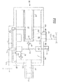
- FIG. 2 illustrates an embodiment of the pressure regulating valve 26 which may be utilized in the Figure 1 system.
- a sense piston 45 may see the pressure on the line 32. As this pressure increases, the sense piston 45 is biased to the right against a valve spool 34.
- Spool 34 includes a valve body and main regulating chamber 52. Regulating main chamber 52 is shown communicating a discharge pressure tap or supply line 125 through a main supply port 111 to a main return line 27 through a main return port 99. As shown, an outer land 50 of the spool 34 is driven to the left or right to block or open the connection between ports 111 and 99.
- a spring 54 mounted about a spring support stem 61 drives the spool 34 to the left as shown in this Figure and against the force from the sense piston 45.
- the spring 54 thus acts in opposition to a pressure increase on the line 32.
- the spool 34 is driven to positions at which it communicates more of the flow from main supply line 125 to the main return line 27.
- the spring 54 drives the spool 34 to positions wherein less of the connection to main return line 27 is open and more is blocked by the land 50 of the spool 34. In this manner, the pressure reaching the heat exchanger 30 is regulated, and unduly high or low pressures do not reach the heat exchanger 30.
- the spool 34 may move at excessively high speeds and, thus, a damper function is provided in the pressure regulating valve 26.
- the damper function is provided by opposed damper volumes or chambers 60/69 and 62.
- the chamber 62 resists movement of the spool 34 to the left.
- the opposed chamber 60 is formed about the spring stem 61 and further includes a chamber 69. The combined chamber 60 and 69 resist movement of the spool 34 to the right.
- connection line 70 connects the chambers 62 and 69 to the return line 27. Damping orifices 66 and 68 resist the flow of the oil from damping chambers 62 and 69 to the connection line 70. This thus serves to limit the speed of movement of the spool 34. As shown, the connection line 70 communicates with the return line 27.
- connection line 70 and the orifices 66 and 68 are preferably within the upper vertical half of a housing 100 for the pressure regulating valve 26. More preferably, they are within an upper 45 degrees either side of vertical and, even more preferably, the passages are mounted at a vertically uppermost or top dead center location on the housing 100. In this manner, any air entrained in the oil within the damping chambers 62 and 60/69 will tend to flow into the connection line 70 and be returned to the sump.
- damper supply line 36 Further urging the air out of the damping chamber volumes is a damper supply line 36.
- the damper supply line 36 may be taken from the discharge line 25 in one embodiment and may be filtered before passing through an orifice 38 and into a damper supply chamber 40 formed within the spool 34. Chamber 40 communicates with a tap 56, which also is returned to the line 27 leading back to the sump 19.
- Chamber 40 communicates with a damper supply passage 42 that passes through a check valve 44 into the chamber 60 and then chamber 69.
- a similar check valve 64 regulates the flow of supply oil through passage 63 into the chamber 62.
- the check valves 64/44 need not be extremely fluid tight, but rather simply need to serve as a resistance to flow from the oil leaving the chambers 62 and 60/69.
- the back-flow resistance of the check valve should be at least an order-of-magnitude greater than the flow resistance of the damper orifice 66 and 68.
- the orifice 38 has an impedance of at least one order of magnitude higher than a return-to-case impedance through a tap 56 to line 27. This ensures that the pressure in chamber 40 is at least one order of magnitude lower than a supply pressure seen on the main supply line 125, thus not significantly skewing an equilibrium position of spool 34, as balanced between pressure 32 and spring 54.
- the tap line 125 communicates with the discharge line 25, which communicates into the main regulating chamber 52.
- the entire flow on the line 25 does not pass through the main regulating chamber 52.
- Figure 3 shows another embodiment 126. Much of the embodiment 126 is similar to Figure 2 and, thus, those portions are identified by the same reference numerals.
- the sense piston 145 now includes an internal passage 140 and a transfer tube 147.
- the transfer tube 147 extends into a bore 149 in the spool 134.
- the passage 140 through the tube 147 connects into the connection passage 42, which can then supply the oil through the check valves 64 and 44 as in the Figure 2 embodiment.
- An orifice 138 is designed to have the similar impedance factor as the orifice 38.
- the supply of oil into the damper chambers 62 and 60/69 ensures that the oil found in those chambers will be relatively air free compared to the prior art and will further serve to drive the air upwardly through the damping orifices 66 and 68 and to the return line 27.
- pressure regulating valves 26 and 126 may be utilized in a generator system, such as shown in Figure 1 , they may also have application in other hydraulic systems requiring a pressure regulating valve function.
Landscapes
- Engineering & Computer Science (AREA)
- General Engineering & Computer Science (AREA)
- Physics & Mathematics (AREA)
- Mechanical Engineering (AREA)
- Fluid Mechanics (AREA)
- General Physics & Mathematics (AREA)
- Automation & Control Theory (AREA)
- Fluid-Damping Devices (AREA)
- Safety Valves (AREA)
- Multiple-Way Valves (AREA)
Applications Claiming Priority (1)
| Application Number | Priority Date | Filing Date | Title |
|---|---|---|---|
| US13/950,611 US9316325B2 (en) | 2013-07-25 | 2013-07-25 | Air purging pressure regulating valve |
Publications (3)
| Publication Number | Publication Date |
|---|---|
| EP2829942A2 true EP2829942A2 (de) | 2015-01-28 |
| EP2829942A3 EP2829942A3 (de) | 2015-02-25 |
| EP2829942B1 EP2829942B1 (de) | 2019-01-02 |
Family
ID=51205255
Family Applications (1)
| Application Number | Title | Priority Date | Filing Date |
|---|---|---|---|
| EP14177120.4A Active EP2829942B1 (de) | 2013-07-25 | 2014-07-15 | Luftspülungsdruckregelventil |
Country Status (2)
| Country | Link |
|---|---|
| US (1) | US9316325B2 (de) |
| EP (1) | EP2829942B1 (de) |
Families Citing this family (2)
| Publication number | Priority date | Publication date | Assignee | Title |
|---|---|---|---|---|
| EP3246781B1 (de) | 2016-05-18 | 2020-06-24 | Microtecnica S.r.l. | Druckregelventil |
| GB2571533B (en) * | 2018-02-28 | 2022-06-08 | Safran Electrical & Power | A coolant system |
Family Cites Families (16)
| Publication number | Priority date | Publication date | Assignee | Title |
|---|---|---|---|---|
| US4161189A (en) | 1976-08-16 | 1979-07-17 | Massey-Ferguson Inc. | Control valve |
| US4168721A (en) | 1977-06-16 | 1979-09-25 | Massey-Ferguson Inc. | Pressure control valve |
| US4531709A (en) * | 1983-12-02 | 1985-07-30 | Dresser Industries, Inc. | Hydraulic control valve with fluid dampening system |
| DE4017074A1 (de) | 1990-05-26 | 1991-11-28 | Mann & Hummel Filter | Druckregelventil fuer die kurbelgehaeuseentlueftung an einer brennkraftmaschine |
| US5163706A (en) | 1991-04-24 | 1992-11-17 | General Motors Corporation | Electro-hydraulic pressure regulating valve assembly for a hydraulic damper |
| DE4115594A1 (de) | 1991-05-14 | 1992-11-19 | Bosch Gmbh Robert | Proportional-druckregelventil |
| JP3601554B2 (ja) | 1995-08-11 | 2004-12-15 | アイシン・エィ・ダブリュ株式会社 | 電磁式圧力調整弁 |
| DE19962960A1 (de) | 1999-12-24 | 2001-06-28 | Bosch Gmbh Robert | Druckregelventil und Verfahren zum Herstellen eines Druckregelventils |
| US6289919B1 (en) | 2000-06-05 | 2001-09-18 | Hamilton Sundstrand Corporation | Pressure regulating valve with integral damping |
| JP4030491B2 (ja) * | 2003-10-15 | 2008-01-09 | 株式会社ケーヒン | 常開型油圧制御弁 |
| JP3784797B2 (ja) * | 2003-10-15 | 2006-06-14 | 株式会社ケーヒン | 油圧制御弁のダンパ装置 |
| JP4258462B2 (ja) | 2004-11-19 | 2009-04-30 | セイコーエプソン株式会社 | 圧力調整弁、機能液供給装置および描画装置 |
| JP4770666B2 (ja) * | 2006-09-21 | 2011-09-14 | 株式会社デンソー | スプール弁 |
| US8485218B2 (en) * | 2009-05-06 | 2013-07-16 | Hamilton Sundstrand Corporation | Oil pressure regulating valve for generator applications |
| US8316880B2 (en) * | 2009-05-08 | 2012-11-27 | Hamilton Sundstrand Corporation | Oil filter bypass valve assembly for a generator |
| US8439073B2 (en) | 2010-09-10 | 2013-05-14 | Hamilton Sundstrand Corporation | Gate valve |
-
2013
- 2013-07-25 US US13/950,611 patent/US9316325B2/en active Active
-
2014
- 2014-07-15 EP EP14177120.4A patent/EP2829942B1/de active Active
Non-Patent Citations (1)
| Title |
|---|
| None |
Also Published As
| Publication number | Publication date |
|---|---|
| US20150027568A1 (en) | 2015-01-29 |
| US9316325B2 (en) | 2016-04-19 |
| EP2829942A3 (de) | 2015-02-25 |
| EP2829942B1 (de) | 2019-01-02 |
Similar Documents
| Publication | Publication Date | Title |
|---|---|---|
| US9068497B2 (en) | Oil supply system for an engine | |
| JP6147655B2 (ja) | ターボチャージャの潤滑油供給機構 | |
| US10794468B2 (en) | Hydraulic system for a transmission of a motor vehicle | |
| JP2014503748A (ja) | 選択可能な出口圧力を有する油ポンプ | |
| US8967195B2 (en) | Pressure relief valve with orifice | |
| KR20120027038A (ko) | 윤활유 펌프 시스템 | |
| US10662977B2 (en) | Vehicle hydraulic system | |
| US9482225B2 (en) | Gear pump, pumping apparatus including the same, and aircraft fuel system including gear pump | |
| CN105090426A (zh) | 包括热力阀的变速器液压控制系统 | |
| EP2829942B1 (de) | Luftspülungsdruckregelventil | |
| CN107061970B (zh) | 具有两件式安全阀的机动车润滑泵系统 | |
| CN106870357A (zh) | 可变排量叶片泵 | |
| US11022157B2 (en) | Cooling-prioritization valve for a hydraulic system of a motor vehicle transmission | |
| US20150338857A1 (en) | Pressure-regulating valves | |
| KR102836519B1 (ko) | 자동차 변속기의 유압 시스템용 시스템 압력 밸브 | |
| US10077834B2 (en) | Hydraulic control system for a transmission | |
| JP6258772B2 (ja) | 内燃機関の流量制御弁 | |
| JP6225009B2 (ja) | ターボチャージャの潤滑油供給機構 | |
| JPH01275905A (ja) | プライオリティ弁 | |
| JP6258773B2 (ja) | 内燃機関の流量制御弁 | |
| JP2016089632A (ja) | ターボチャージャの潤滑油供給機構 | |
| US11988277B2 (en) | Hydraulic system for a transmission of a motor vehicle | |
| KR102577037B1 (ko) | 오일펌프용 릴리프 밸브 | |
| US20140099223A1 (en) | Cold start valve and hydraulic arrangement having a cold start valve of this type | |
| JP6213358B2 (ja) | 車両用油圧制御装置 |
Legal Events
| Date | Code | Title | Description |
|---|---|---|---|
| PUAL | Search report despatched |
Free format text: ORIGINAL CODE: 0009013 |
|
| 17P | Request for examination filed |
Effective date: 20140715 |
|
| AK | Designated contracting states |
Kind code of ref document: A2 Designated state(s): AL AT BE BG CH CY CZ DE DK EE ES FI FR GB GR HR HU IE IS IT LI LT LU LV MC MK MT NL NO PL PT RO RS SE SI SK SM TR |
|
| AX | Request for extension of the european patent |
Extension state: BA ME |
|
| PUAI | Public reference made under article 153(3) epc to a published international application that has entered the european phase |
Free format text: ORIGINAL CODE: 0009012 |
|
| AK | Designated contracting states |
Kind code of ref document: A3 Designated state(s): AL AT BE BG CH CY CZ DE DK EE ES FI FR GB GR HR HU IE IS IT LI LT LU LV MC MK MT NL NO PL PT RO RS SE SI SK SM TR |
|
| AX | Request for extension of the european patent |
Extension state: BA ME |
|
| RIC1 | Information provided on ipc code assigned before grant |
Ipc: G05D 16/10 20060101AFI20150119BHEP |
|
| R17P | Request for examination filed (corrected) |
Effective date: 20150804 |
|
| RBV | Designated contracting states (corrected) |
Designated state(s): AL AT BE BG CH CY CZ DE DK EE ES FI FR GB GR HR HU IE IS IT LI LT LU LV MC MK MT NL NO PL PT RO RS SE SI SK SM TR |
|
| GRAP | Despatch of communication of intention to grant a patent |
Free format text: ORIGINAL CODE: EPIDOSNIGR1 |
|
| STAA | Information on the status of an ep patent application or granted ep patent |
Free format text: STATUS: GRANT OF PATENT IS INTENDED |
|
| INTG | Intention to grant announced |
Effective date: 20180726 |
|
| GRAS | Grant fee paid |
Free format text: ORIGINAL CODE: EPIDOSNIGR3 |
|
| GRAA | (expected) grant |
Free format text: ORIGINAL CODE: 0009210 |
|
| STAA | Information on the status of an ep patent application or granted ep patent |
Free format text: STATUS: THE PATENT HAS BEEN GRANTED |
|
| AK | Designated contracting states |
Kind code of ref document: B1 Designated state(s): AL AT BE BG CH CY CZ DE DK EE ES FI FR GB GR HR HU IE IS IT LI LT LU LV MC MK MT NL NO PL PT RO RS SE SI SK SM TR |
|
| REG | Reference to a national code |
Ref country code: GB Ref legal event code: FG4D |
|
| REG | Reference to a national code |
Ref country code: CH Ref legal event code: EP Ref country code: AT Ref legal event code: REF Ref document number: 1085183 Country of ref document: AT Kind code of ref document: T Effective date: 20190115 |
|
| REG | Reference to a national code |
Ref country code: DE Ref legal event code: R096 Ref document number: 602014038984 Country of ref document: DE |
|
| REG | Reference to a national code |
Ref country code: IE Ref legal event code: FG4D |
|
| REG | Reference to a national code |
Ref country code: NL Ref legal event code: MP Effective date: 20190102 |
|
| REG | Reference to a national code |
Ref country code: LT Ref legal event code: MG4D |
|
| REG | Reference to a national code |
Ref country code: AT Ref legal event code: MK05 Ref document number: 1085183 Country of ref document: AT Kind code of ref document: T Effective date: 20190102 |
|
| PG25 | Lapsed in a contracting state [announced via postgrant information from national office to epo] |
Ref country code: NL Free format text: LAPSE BECAUSE OF FAILURE TO SUBMIT A TRANSLATION OF THE DESCRIPTION OR TO PAY THE FEE WITHIN THE PRESCRIBED TIME-LIMIT Effective date: 20190102 |
|
| PG25 | Lapsed in a contracting state [announced via postgrant information from national office to epo] |
Ref country code: NO Free format text: LAPSE BECAUSE OF FAILURE TO SUBMIT A TRANSLATION OF THE DESCRIPTION OR TO PAY THE FEE WITHIN THE PRESCRIBED TIME-LIMIT Effective date: 20190402 Ref country code: FI Free format text: LAPSE BECAUSE OF FAILURE TO SUBMIT A TRANSLATION OF THE DESCRIPTION OR TO PAY THE FEE WITHIN THE PRESCRIBED TIME-LIMIT Effective date: 20190102 Ref country code: PT Free format text: LAPSE BECAUSE OF FAILURE TO SUBMIT A TRANSLATION OF THE DESCRIPTION OR TO PAY THE FEE WITHIN THE PRESCRIBED TIME-LIMIT Effective date: 20190502 Ref country code: SE Free format text: LAPSE BECAUSE OF FAILURE TO SUBMIT A TRANSLATION OF THE DESCRIPTION OR TO PAY THE FEE WITHIN THE PRESCRIBED TIME-LIMIT Effective date: 20190102 Ref country code: PL Free format text: LAPSE BECAUSE OF FAILURE TO SUBMIT A TRANSLATION OF THE DESCRIPTION OR TO PAY THE FEE WITHIN THE PRESCRIBED TIME-LIMIT Effective date: 20190102 Ref country code: ES Free format text: LAPSE BECAUSE OF FAILURE TO SUBMIT A TRANSLATION OF THE DESCRIPTION OR TO PAY THE FEE WITHIN THE PRESCRIBED TIME-LIMIT Effective date: 20190102 Ref country code: LT Free format text: LAPSE BECAUSE OF FAILURE TO SUBMIT A TRANSLATION OF THE DESCRIPTION OR TO PAY THE FEE WITHIN THE PRESCRIBED TIME-LIMIT Effective date: 20190102 |
|
| PG25 | Lapsed in a contracting state [announced via postgrant information from national office to epo] |
Ref country code: LV Free format text: LAPSE BECAUSE OF FAILURE TO SUBMIT A TRANSLATION OF THE DESCRIPTION OR TO PAY THE FEE WITHIN THE PRESCRIBED TIME-LIMIT Effective date: 20190102 Ref country code: HR Free format text: LAPSE BECAUSE OF FAILURE TO SUBMIT A TRANSLATION OF THE DESCRIPTION OR TO PAY THE FEE WITHIN THE PRESCRIBED TIME-LIMIT Effective date: 20190102 Ref country code: IS Free format text: LAPSE BECAUSE OF FAILURE TO SUBMIT A TRANSLATION OF THE DESCRIPTION OR TO PAY THE FEE WITHIN THE PRESCRIBED TIME-LIMIT Effective date: 20190502 Ref country code: GR Free format text: LAPSE BECAUSE OF FAILURE TO SUBMIT A TRANSLATION OF THE DESCRIPTION OR TO PAY THE FEE WITHIN THE PRESCRIBED TIME-LIMIT Effective date: 20190403 Ref country code: BG Free format text: LAPSE BECAUSE OF FAILURE TO SUBMIT A TRANSLATION OF THE DESCRIPTION OR TO PAY THE FEE WITHIN THE PRESCRIBED TIME-LIMIT Effective date: 20190402 Ref country code: RS Free format text: LAPSE BECAUSE OF FAILURE TO SUBMIT A TRANSLATION OF THE DESCRIPTION OR TO PAY THE FEE WITHIN THE PRESCRIBED TIME-LIMIT Effective date: 20190102 |
|
| REG | Reference to a national code |
Ref country code: DE Ref legal event code: R097 Ref document number: 602014038984 Country of ref document: DE |
|
| PG25 | Lapsed in a contracting state [announced via postgrant information from national office to epo] |
Ref country code: DK Free format text: LAPSE BECAUSE OF FAILURE TO SUBMIT A TRANSLATION OF THE DESCRIPTION OR TO PAY THE FEE WITHIN THE PRESCRIBED TIME-LIMIT Effective date: 20190102 Ref country code: IT Free format text: LAPSE BECAUSE OF FAILURE TO SUBMIT A TRANSLATION OF THE DESCRIPTION OR TO PAY THE FEE WITHIN THE PRESCRIBED TIME-LIMIT Effective date: 20190102 Ref country code: AT Free format text: LAPSE BECAUSE OF FAILURE TO SUBMIT A TRANSLATION OF THE DESCRIPTION OR TO PAY THE FEE WITHIN THE PRESCRIBED TIME-LIMIT Effective date: 20190102 Ref country code: EE Free format text: LAPSE BECAUSE OF FAILURE TO SUBMIT A TRANSLATION OF THE DESCRIPTION OR TO PAY THE FEE WITHIN THE PRESCRIBED TIME-LIMIT Effective date: 20190102 Ref country code: CZ Free format text: LAPSE BECAUSE OF FAILURE TO SUBMIT A TRANSLATION OF THE DESCRIPTION OR TO PAY THE FEE WITHIN THE PRESCRIBED TIME-LIMIT Effective date: 20190102 Ref country code: RO Free format text: LAPSE BECAUSE OF FAILURE TO SUBMIT A TRANSLATION OF THE DESCRIPTION OR TO PAY THE FEE WITHIN THE PRESCRIBED TIME-LIMIT Effective date: 20190102 Ref country code: SK Free format text: LAPSE BECAUSE OF FAILURE TO SUBMIT A TRANSLATION OF THE DESCRIPTION OR TO PAY THE FEE WITHIN THE PRESCRIBED TIME-LIMIT Effective date: 20190102 Ref country code: AL Free format text: LAPSE BECAUSE OF FAILURE TO SUBMIT A TRANSLATION OF THE DESCRIPTION OR TO PAY THE FEE WITHIN THE PRESCRIBED TIME-LIMIT Effective date: 20190102 |
|
| PLBE | No opposition filed within time limit |
Free format text: ORIGINAL CODE: 0009261 |
|
| STAA | Information on the status of an ep patent application or granted ep patent |
Free format text: STATUS: NO OPPOSITION FILED WITHIN TIME LIMIT |
|
| PG25 | Lapsed in a contracting state [announced via postgrant information from national office to epo] |
Ref country code: SM Free format text: LAPSE BECAUSE OF FAILURE TO SUBMIT A TRANSLATION OF THE DESCRIPTION OR TO PAY THE FEE WITHIN THE PRESCRIBED TIME-LIMIT Effective date: 20190102 |
|
| 26N | No opposition filed |
Effective date: 20191003 |
|
| PG25 | Lapsed in a contracting state [announced via postgrant information from national office to epo] |
Ref country code: SI Free format text: LAPSE BECAUSE OF FAILURE TO SUBMIT A TRANSLATION OF THE DESCRIPTION OR TO PAY THE FEE WITHIN THE PRESCRIBED TIME-LIMIT Effective date: 20190102 Ref country code: MC Free format text: LAPSE BECAUSE OF FAILURE TO SUBMIT A TRANSLATION OF THE DESCRIPTION OR TO PAY THE FEE WITHIN THE PRESCRIBED TIME-LIMIT Effective date: 20190102 |
|
| REG | Reference to a national code |
Ref country code: CH Ref legal event code: PL |
|
| PG25 | Lapsed in a contracting state [announced via postgrant information from national office to epo] |
Ref country code: TR Free format text: LAPSE BECAUSE OF FAILURE TO SUBMIT A TRANSLATION OF THE DESCRIPTION OR TO PAY THE FEE WITHIN THE PRESCRIBED TIME-LIMIT Effective date: 20190102 |
|
| REG | Reference to a national code |
Ref country code: BE Ref legal event code: MM Effective date: 20190731 |
|
| PG25 | Lapsed in a contracting state [announced via postgrant information from national office to epo] |
Ref country code: BE Free format text: LAPSE BECAUSE OF NON-PAYMENT OF DUE FEES Effective date: 20190731 Ref country code: LU Free format text: LAPSE BECAUSE OF NON-PAYMENT OF DUE FEES Effective date: 20190715 Ref country code: CH Free format text: LAPSE BECAUSE OF NON-PAYMENT OF DUE FEES Effective date: 20190731 Ref country code: LI Free format text: LAPSE BECAUSE OF NON-PAYMENT OF DUE FEES Effective date: 20190731 |
|
| PG25 | Lapsed in a contracting state [announced via postgrant information from national office to epo] |
Ref country code: IE Free format text: LAPSE BECAUSE OF NON-PAYMENT OF DUE FEES Effective date: 20190715 |
|
| PG25 | Lapsed in a contracting state [announced via postgrant information from national office to epo] |
Ref country code: CY Free format text: LAPSE BECAUSE OF FAILURE TO SUBMIT A TRANSLATION OF THE DESCRIPTION OR TO PAY THE FEE WITHIN THE PRESCRIBED TIME-LIMIT Effective date: 20190102 |
|
| PG25 | Lapsed in a contracting state [announced via postgrant information from national office to epo] |
Ref country code: MT Free format text: LAPSE BECAUSE OF FAILURE TO SUBMIT A TRANSLATION OF THE DESCRIPTION OR TO PAY THE FEE WITHIN THE PRESCRIBED TIME-LIMIT Effective date: 20190102 Ref country code: HU Free format text: LAPSE BECAUSE OF FAILURE TO SUBMIT A TRANSLATION OF THE DESCRIPTION OR TO PAY THE FEE WITHIN THE PRESCRIBED TIME-LIMIT; INVALID AB INITIO Effective date: 20140715 |
|
| PG25 | Lapsed in a contracting state [announced via postgrant information from national office to epo] |
Ref country code: MK Free format text: LAPSE BECAUSE OF FAILURE TO SUBMIT A TRANSLATION OF THE DESCRIPTION OR TO PAY THE FEE WITHIN THE PRESCRIBED TIME-LIMIT Effective date: 20190102 |
|
| P01 | Opt-out of the competence of the unified patent court (upc) registered |
Effective date: 20230522 |
|
| PGFP | Annual fee paid to national office [announced via postgrant information from national office to epo] |
Ref country code: GB Payment date: 20250619 Year of fee payment: 12 |
|
| PGFP | Annual fee paid to national office [announced via postgrant information from national office to epo] |
Ref country code: FR Payment date: 20250619 Year of fee payment: 12 |
|
| PGFP | Annual fee paid to national office [announced via postgrant information from national office to epo] |
Ref country code: DE Payment date: 20250620 Year of fee payment: 12 |