EP2829782B1 - Sattel für einen Abzweigungsanschluss - Google Patents
Sattel für einen Abzweigungsanschluss Download PDFInfo
- Publication number
- EP2829782B1 EP2829782B1 EP13177523.1A EP13177523A EP2829782B1 EP 2829782 B1 EP2829782 B1 EP 2829782B1 EP 13177523 A EP13177523 A EP 13177523A EP 2829782 B1 EP2829782 B1 EP 2829782B1
- Authority
- EP
- European Patent Office
- Prior art keywords
- saddle
- groove
- seal
- cheek
- course
- Prior art date
- Legal status (The legal status is an assumption and is not a legal conclusion. Google has not performed a legal analysis and makes no representation as to the accuracy of the status listed.)
- Active
Links
Images

Classifications
-
- F—MECHANICAL ENGINEERING; LIGHTING; HEATING; WEAPONS; BLASTING
- F16—ENGINEERING ELEMENTS AND UNITS; GENERAL MEASURES FOR PRODUCING AND MAINTAINING EFFECTIVE FUNCTIONING OF MACHINES OR INSTALLATIONS; THERMAL INSULATION IN GENERAL
- F16K—VALVES; TAPS; COCKS; ACTUATING-FLOATS; DEVICES FOR VENTING OR AERATING
- F16K25/00—Details relating to contact between valve members and seats
-
- F—MECHANICAL ENGINEERING; LIGHTING; HEATING; WEAPONS; BLASTING
- F16—ENGINEERING ELEMENTS AND UNITS; GENERAL MEASURES FOR PRODUCING AND MAINTAINING EFFECTIVE FUNCTIONING OF MACHINES OR INSTALLATIONS; THERMAL INSULATION IN GENERAL
- F16J—PISTONS; CYLINDERS; SEALINGS
- F16J15/00—Sealings
- F16J15/02—Sealings between relatively-stationary surfaces
- F16J15/021—Sealings between relatively-stationary surfaces with elastic packing
- F16J15/022—Sealings between relatively-stationary surfaces with elastic packing characterised by structure or material
-
- F—MECHANICAL ENGINEERING; LIGHTING; HEATING; WEAPONS; BLASTING
- F16—ENGINEERING ELEMENTS AND UNITS; GENERAL MEASURES FOR PRODUCING AND MAINTAINING EFFECTIVE FUNCTIONING OF MACHINES OR INSTALLATIONS; THERMAL INSULATION IN GENERAL
- F16L—PIPES; JOINTS OR FITTINGS FOR PIPES; SUPPORTS FOR PIPES, CABLES OR PROTECTIVE TUBING; MEANS FOR THERMAL INSULATION IN GENERAL
- F16L17/00—Joints with packing adapted to sealing by fluid pressure
- F16L17/02—Joints with packing adapted to sealing by fluid pressure with sealing rings arranged between outer surface of pipe and inner surface of sleeve or socket
- F16L17/025—Joints with packing adapted to sealing by fluid pressure with sealing rings arranged between outer surface of pipe and inner surface of sleeve or socket the sealing rings having radially directed ribs
-
- F—MECHANICAL ENGINEERING; LIGHTING; HEATING; WEAPONS; BLASTING
- F16—ENGINEERING ELEMENTS AND UNITS; GENERAL MEASURES FOR PRODUCING AND MAINTAINING EFFECTIVE FUNCTIONING OF MACHINES OR INSTALLATIONS; THERMAL INSULATION IN GENERAL
- F16L—PIPES; JOINTS OR FITTINGS FOR PIPES; SUPPORTS FOR PIPES, CABLES OR PROTECTIVE TUBING; MEANS FOR THERMAL INSULATION IN GENERAL
- F16L17/00—Joints with packing adapted to sealing by fluid pressure
- F16L17/02—Joints with packing adapted to sealing by fluid pressure with sealing rings arranged between outer surface of pipe and inner surface of sleeve or socket
- F16L17/03—Joints with packing adapted to sealing by fluid pressure with sealing rings arranged between outer surface of pipe and inner surface of sleeve or socket having annular axial lips
- F16L17/035—Joints with packing adapted to sealing by fluid pressure with sealing rings arranged between outer surface of pipe and inner surface of sleeve or socket having annular axial lips the sealing rings having two lips parallel to each other
-
- F—MECHANICAL ENGINEERING; LIGHTING; HEATING; WEAPONS; BLASTING
- F16—ENGINEERING ELEMENTS AND UNITS; GENERAL MEASURES FOR PRODUCING AND MAINTAINING EFFECTIVE FUNCTIONING OF MACHINES OR INSTALLATIONS; THERMAL INSULATION IN GENERAL
- F16L—PIPES; JOINTS OR FITTINGS FOR PIPES; SUPPORTS FOR PIPES, CABLES OR PROTECTIVE TUBING; MEANS FOR THERMAL INSULATION IN GENERAL
- F16L41/00—Branching pipes; Joining pipes to walls
- F16L41/08—Joining pipes to walls or pipes, the joined pipe axis being perpendicular to the plane of a wall or to the axis of another pipe
- F16L41/12—Joining pipes to walls or pipes, the joined pipe axis being perpendicular to the plane of a wall or to the axis of another pipe using attaching means embracing the pipe
-
- F—MECHANICAL ENGINEERING; LIGHTING; HEATING; WEAPONS; BLASTING
- F16—ENGINEERING ELEMENTS AND UNITS; GENERAL MEASURES FOR PRODUCING AND MAINTAINING EFFECTIVE FUNCTIONING OF MACHINES OR INSTALLATIONS; THERMAL INSULATION IN GENERAL
- F16L—PIPES; JOINTS OR FITTINGS FOR PIPES; SUPPORTS FOR PIPES, CABLES OR PROTECTIVE TUBING; MEANS FOR THERMAL INSULATION IN GENERAL
- F16L47/00—Connecting arrangements or other fittings specially adapted to be made of plastics or to be used with pipes made of plastics
- F16L47/26—Connecting arrangements or other fittings specially adapted to be made of plastics or to be used with pipes made of plastics for branching pipes; for joining pipes to walls; Adaptors therefor
- F16L47/28—Joining pipes to walls or to other pipes, the axis of the joined pipe being perpendicular to the wall or to the axis of the other pipe
- F16L47/30—Joining pipes to walls or to other pipes, the axis of the joined pipe being perpendicular to the wall or to the axis of the other pipe using attaching means embracing the pipe
Definitions
- the invention relates to a saddle, in particular a clamping saddle for plastic pipes containing a Abzweigansatz, a saddle, central axes (X), (Y) and (Z) and a groove for the arrangement of a seal and an assembly comprising the saddle and the seal.
- Saddles of this type are known from the prior art. They are used to connect branch pipes to media-carrying pipes. Usually tapping fittings are used which are fastened by means of such saddles on the media-carrying pipe, whether by clamps or by other means of attachment. Furthermore, such saddles also serve to connect the branching lines or other fittings such as valves, etc.
- the CH 589 250 discloses a branch fitting, which is composed of a lower half-shell and the saddle or upper half-shell, which can be clamped around the base pipe.
- a seal runs around the connection opening for the branch around. It serves to seal the gap between the saddle and the base pipeline.
- the groove in the saddle slicing plane 90 ° to the pipe axis has a different cross-sectional area and cross-sectional contour than in the saddle slicing plane along the pipe axis.
- This in turn has the consequence that at the extreme points of Nutverlaufs, along the saddle sectional plane, 90 ° to the pipeline, the O-ring can be flushed laterally, since there the angle between the outer wall of the groove and the tangent to the pipe outer surface is maximally pointed, which promotes rinsing at this position.
- the inner cheek of the groove prevents the O-ring from being able to adapt to the geometrically optimal requirements for it.
- the EP 2 090 816 B1 discloses a seal which serves to seal a pipe and a tapping sleeve to be connected thereto. Due to the pre-curvature of the seal, compressions of the seal should be avoided and thus a gap formation can be prevented. In addition, the specific design of this seal should ensure the tightness. A disadvantage of this seal are the high mounting requirements, so that the seal is properly installed.
- DE 11 11 469 B and DE also have saddles for connection to piping and appropriate seals with the designated grooves, with hardly an optimal tightness can be guaranteed at elevated internal pressures.
- the present invention provides a better sealing performance when lifting the saddle, which can occur due to increasing internal pressure or change in the thermal state.
- the inner cheek of the groove over the entire course of the groove perpendicular to the inner surface of the saddle piece is arranged, wherein the outer cheek of the groove extends at no position of the entire course of the groove parallel to the inner cheek.
- the conditions for the seal are therefore the same at every position of Nutverlaufs.
- the inner surface of the saddle corresponds to the outer surface of the tube to which the saddle is attached, whereby the inner cheek is also directed perpendicular to the outer surface of the tube.
- the saddle is preferably made of plastic and in particular by the injection molding process.
- Preferred plastics used for this purpose are engineering plastics, in particular POM, PP GF 30 or PVC.
- a preferred embodiment is that the contour of the groove cross-section or the shape over the entire course of the groove is constant. The shape of the groove is therefore the same at each position, whereby the corresponding seal receives constant conditions. The pressure on the seal is thus the same everywhere, whereby critical points at which the seal tends to flush out as known from the prior art, can be avoided.
- the groove runs constantly along the inner surface of the saddle piece. According to the size of the saddle or the size of the branch pipe to be connected and its bore and the pipe diameter of the pipe to which the saddle is fastened, the cross-sectional contour of the groove and thus also of the corresponding seal results.
- ⁇ arcsin ((inner diameter connecting pipe (d2)) / (outside diameter pipe to which the saddle is attached (D1))) + about 5 °
- the groove is arranged concentrically, radially offset from the inner diameter of the pipe to be connected so as not to directly affect the lateral surface of the bore.
- the concentric offset to the lateral surface of the connection bore of the groove may also be less than or greater than 5 °. It is preferably in a range of 2-10 °, corresponding to the groove closer or farther to the lateral surface of the bore, passing through the saddle along the Central axis (Y) protrudes.
- the angle ⁇ between the inner cheek of the groove and outer cheek, over the entire course of the groove at least 20 °.
- the angle does not exceed the amount of 45 °.
- the cross-sectional contour and thus also the cross-sectional area of the groove is dependent on the dimension of the saddle or the arrangement of the groove with respect to the center axis (Y) of the saddle and the diameter of the tube to which the saddle is attached. Thus arise according to the sizes different angles.
- the definition of the contour is based on the extreme point, which lies on the cutting plane of the saddle 90 ° to the axis of the tube to which the saddle is attached.
- the outer cheek runs parallel to the axis of the saddle or at right angles to the transverse axis of the tube.
- the inner cheek is perpendicular to the inner surface of the saddle piece or the outer surface of the tube, with usually 1 ° deviation of the vertical course for optimal demolding or as Entformungselle is tolerated.
- the depth of the groove is carried out according to the seal.
- the invention is additionally distinguished by the fact that the cross-sectional area is constant.
- the inner surface of the saddle piece corresponds to the outer surface of the tube on which the saddle or clamping saddle is arranged.
- the seal has an angle ⁇ which corresponds to the angle ⁇ of the groove. Furthermore, a preload on the seal is effected during assembly of the saddle to ensure optimum sealing behavior.
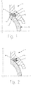
- a saddle (1) can be seen for a tapping fitting known in the art.
- an O-ring (8) is used, whereby other seals could be used which are also known from the prior art.
- Most such saddles (1) are made of plastic by the Spritzgeiss vide. This in turn requires that the saddle (1) is malleable, or the cores can be removed. Due to this, the course of the inner and outer cheeks of the (6, 7) groove (4) is parallel to each other and to Center axis (Y) of the saddle (1), which allows easy molding.
- a disadvantage is the resulting arrangement of the O-ring (8) in this groove (4).
- the cross-sectional area and the cross-sectional contour of the groove (4) changes over the Nutverlauf.
- the cross-sectional area and the contour of the groove (4) along the cutting plane of the saddle (1) parallel to the axis (Z) of the pipe do not correspond to the same area and contour as in FIG Fig. 1 in which the sectional plane of the saddle (1) 90 ° to the tube axis (Z) is shown.
- the seal (8) is not subject to optimum installation conditions over the entire course of the groove (4).
- FIG. 2 shows a groove (4), the constant for the arrangement of a seal or an O-ring entire course of the groove (4), whereby the seal is subject to the same conditions everywhere.
- This shape of the groove (4) is injection molding technology not or only with enormous effort to produce, as by the alignment of the outer cheek (7) perpendicular to the inner surface (9) of the saddle piece (3) creates an undercut, whereby the injection molded part is no longer ausformbar ,
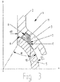
- Fig. 3 shows the sectional view analogous to Fig. 1 and 2 , It can be seen that the inner wall (6) of the groove (4) over the entire Nutverlauf perpendicular to the inner surface (9) of the saddle piece (3) is directed, which gives the seal (11) the possibility of optimal deployment without as from The prior art known to be restricted or limited.
- the preload is evenly distributed on the seal on the circumference.
- the formability is given when the inner cheek (6) over the entire course of the groove (4) constant perpendicular to the inner surface (9) of the Saddle piece (3) is directed.
- the outer cheek (7) extends in the extreme point (E) parallel to the central axis (Y) of the saddle (1) as in Fig. 3 shown where a tolerance of about 1 ° draft angle may be present.
- the groove (4) runs constantly with the same contour and surface, which has the advantage that the seal (11) is not squashed or squeezed unevenly anywhere.
- the angle ⁇ results according to the arrangement of the inner cheek (6) of the groove (4) in the saddle piece (3), which is defined by the inner diameter (d2) of the bore of the branch set with the concentric spacing to the outer surface of the bore (d2) of approx 5 ° and the diameter of the tube (5) on which the saddle (1) is fixed.
- the angle ( ⁇ ) remains constant over the course of the groove (4).
- Fig. 4 shows the saddle (1) in a 90 ° rotated sectional view Fig. 3 , It can be seen that the groove (4) in this position has the same contour as well as the same cross-sectional area.
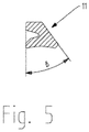
- Fig. 5 shows the cross-sectional area of a seal (11) according to the invention.
- the seal is made of a flexible plastic that can be easily inserted into the groove (4).
- the angle ⁇ of the groove corresponds to the angle ⁇ of the seal (11).
- the seal (11) has a shape which makes it possible to give a preload on the seal (11) when fastening the saddle (1).
- the seal is made of elastomers, in particular EPDM or FPM.
- the entire configuration of sealing groove and seal allows to use a non-preloaded seal. Thus, the installation of the seal with respect to its position in the sealing groove is not critical.
Landscapes
- Engineering & Computer Science (AREA)
- General Engineering & Computer Science (AREA)
- Mechanical Engineering (AREA)
- Physics & Mathematics (AREA)
- Fluid Mechanics (AREA)
- Branch Pipes, Bends, And The Like (AREA)
- Gasket Seals (AREA)
- Bridges Or Land Bridges (AREA)
Priority Applications (6)
| Application Number | Priority Date | Filing Date | Title |
|---|---|---|---|
| EP13177523.1A EP2829782B1 (de) | 2013-07-23 | 2013-07-23 | Sattel für einen Abzweigungsanschluss |
| ES13177523.1T ES2671939T3 (es) | 2013-07-23 | 2013-07-23 | Silleta para una conexión de bifurcación |
| AU2014203263A AU2014203263B2 (en) | 2013-07-23 | 2014-06-16 | Saddle for a branch connection |
| RU2014124857A RU2666028C2 (ru) | 2013-07-23 | 2014-06-18 | Седло для ответвительного соединения |
| IL233646A IL233646A (he) | 2013-07-23 | 2014-07-14 | אוכף לחיבור ענף |
| US14/334,834 US9255641B2 (en) | 2013-07-23 | 2014-07-18 | Saddle for a branch connection |
Applications Claiming Priority (1)
| Application Number | Priority Date | Filing Date | Title |
|---|---|---|---|
| EP13177523.1A EP2829782B1 (de) | 2013-07-23 | 2013-07-23 | Sattel für einen Abzweigungsanschluss |
Publications (2)
| Publication Number | Publication Date |
|---|---|
| EP2829782A1 EP2829782A1 (de) | 2015-01-28 |
| EP2829782B1 true EP2829782B1 (de) | 2018-04-04 |
Family
ID=48875543
Family Applications (1)
| Application Number | Title | Priority Date | Filing Date |
|---|---|---|---|
| EP13177523.1A Active EP2829782B1 (de) | 2013-07-23 | 2013-07-23 | Sattel für einen Abzweigungsanschluss |
Country Status (6)
| Country | Link |
|---|---|
| US (1) | US9255641B2 (he) |
| EP (1) | EP2829782B1 (he) |
| AU (1) | AU2014203263B2 (he) |
| ES (1) | ES2671939T3 (he) |
| IL (1) | IL233646A (he) |
| RU (1) | RU2666028C2 (he) |
Families Citing this family (8)
| Publication number | Priority date | Publication date | Assignee | Title |
|---|---|---|---|---|
| ES2990983T3 (es) | 2016-03-01 | 2024-12-02 | Fischer G Rohrleitungssysteme Ag | Herramienta de pelar y cortar |
| EP3550291A1 (de) | 2018-04-05 | 2019-10-09 | Georg Fischer Rohrleitungssysteme AG | Befestigungsvorrichtung für messgeräte an rohren |
| ES2930261T3 (es) | 2018-12-13 | 2022-12-09 | Fischer G Rohrleitungssysteme Ag | Compensador de longitud |
| EP3816621A1 (de) | 2019-10-30 | 2021-05-05 | Georg Fischer Rohrleitungssysteme AG | Prüfung einer muffenschweissung |
| EP3816620B1 (de) | 2019-10-30 | 2025-07-02 | Georg Fischer Rohrleitungssysteme AG | Schweissnahtprüfkette |
| KR102702884B1 (ko) * | 2021-11-26 | 2024-09-05 | 주식회사 화승알앤에이 | 에어컨 배관 시스템 및 이의 제작 방법 |
| US20240003455A1 (en) * | 2022-06-30 | 2024-01-04 | A. Y. Mcdonald Mfg. Co. | Hybrid direct tap corporation stop |
| US12297691B2 (en) * | 2023-05-11 | 2025-05-13 | Applied Materials, Inc. | Seal mechanism for load port doors |
Family Cites Families (17)
| Publication number | Priority date | Publication date | Assignee | Title |
|---|---|---|---|---|
| US931011A (en) * | 1908-09-08 | 1909-08-10 | Charles Gilbert Hawley | Muffler cut-out for automobiles. |
| US1641879A (en) * | 1924-03-06 | 1927-09-06 | Gurdon G Brady | Pipe saddle |
| US1770960A (en) * | 1926-10-29 | 1930-07-22 | Mueller Co | Plumbing service clamp |
| US2684859A (en) * | 1950-03-31 | 1954-07-27 | Lock Joint Pipe Co | Saddle type branch pipe connection |
| US2973976A (en) * | 1957-08-19 | 1961-03-07 | William F Steinen | Nozzle mounting adapter for in line pipe and tube installations |
| DE1111469B (de) * | 1958-08-25 | 1961-07-20 | Rheinisches Metallwerk Gmbh | Rohranbohrschelle, insbesondere fuer Versorgungsleitungen aus Kunststoff |
| US3737180A (en) * | 1971-03-22 | 1973-06-05 | Kurier Corp | Pipe clamp |
| US3807435A (en) * | 1972-06-05 | 1974-04-30 | United States Pipe Foundry | Compression seal tapping sleeve |
| NL176883C (nl) | 1974-09-13 | 1985-06-17 | Polva Nederland Bv | Aftakverbinding aan een hoofdleiding. |
| GB1512546A (en) * | 1974-10-01 | 1978-06-01 | Francis R | Pipe tapping bands |
| US3999785A (en) * | 1974-11-18 | 1976-12-28 | Victaulic Company Of Canada, Ltd. | Mechanical pipe outlet |
| SU646133A1 (ru) * | 1976-08-01 | 1979-02-05 | Специальное Конструкторское Бюро "Ленгидросталь" | Шарнирное соединение трубопроводов |
| DE3213212C1 (de) * | 1982-04-08 | 1983-07-07 | Rehau Plastiks Ag & Co, 8673 Rehau | Rohrabzweig |
| SU1425407A1 (ru) * | 1986-03-20 | 1988-09-23 | Ленинградский Филиал Проектно-Технологического Института "Энергомонтажпроект" | Разъемное соединение штуцера с трубопроводом |
| JP5236962B2 (ja) | 2008-02-18 | 2013-07-17 | 株式会社ミツトヨ | 被測定物の表裏面測定方法 |
| DK2090816T3 (da) * | 2008-02-18 | 2010-09-13 | Freudenberg Carl Kg | Krum tætning til en anboringsbøjle |
| AU2010200139A1 (en) * | 2009-01-19 | 2010-08-05 | Fieldmour Engineering Pty. Limited | Method and apparatus to join PVC pipe to metal fittings |
-
2013
- 2013-07-23 EP EP13177523.1A patent/EP2829782B1/de active Active
- 2013-07-23 ES ES13177523.1T patent/ES2671939T3/es active Active
-
2014
- 2014-06-16 AU AU2014203263A patent/AU2014203263B2/en not_active Ceased
- 2014-06-18 RU RU2014124857A patent/RU2666028C2/ru active
- 2014-07-14 IL IL233646A patent/IL233646A/he active IP Right Grant
- 2014-07-18 US US14/334,834 patent/US9255641B2/en active Active
Non-Patent Citations (1)
| Title |
|---|
| None * |
Also Published As
| Publication number | Publication date |
|---|---|
| US9255641B2 (en) | 2016-02-09 |
| ES2671939T3 (es) | 2018-06-11 |
| RU2666028C2 (ru) | 2018-09-05 |
| RU2014124857A (ru) | 2015-12-27 |
| AU2014203263B2 (en) | 2018-12-20 |
| IL233646A (he) | 2017-11-30 |
| US20150028581A1 (en) | 2015-01-29 |
| AU2014203263A1 (en) | 2015-02-12 |
| EP2829782A1 (de) | 2015-01-28 |
Similar Documents
| Publication | Publication Date | Title |
|---|---|---|
| EP2829782B1 (de) | Sattel für einen Abzweigungsanschluss | |
| EP3114378B1 (de) | Dichtung | |
| DE102013009650A1 (de) | Ventil | |
| WO2015135812A1 (de) | Kupplung für rohrelemente | |
| EP2775187B1 (de) | Vorrichtung für eine schlaucharmatur | |
| DE3443942C2 (de) | Rohrverbindung mit mindestens einem Abzweigstutzen | |
| DE202007010592U1 (de) | Anordnung zur Befestigung einer Leitung mit einem profilierten Außendurchmesser | |
| EP3746692B1 (de) | Wasserleitung mit rohrfitting | |
| DE3719585C2 (de) | Lösbare dichte Verbindung zweier benachbarter Rohrleitungen | |
| DE102010016972A1 (de) | Anschlussverbindung für ein Rohr | |
| EP2812619A1 (de) | Rohrkupplung | |
| DE2500552C2 (de) | Sicherungsventil fuer rohr- bzw. schlauchbrueche | |
| DE102014217410B4 (de) | Fluidleitende Verbindungsanordnung sowie Klemmring | |
| EP2366930A1 (de) | Vorrichtung zum Verbinden mit einer Rohr- oder Schlauchleitung, insbesondere Klemmringverschraubung | |
| DE102007023160A1 (de) | Hydraulik- und/oder Pneumatikvorrichtung sowie Hydraulik- und/oder Pneumatiksystem | |
| DE19544222A1 (de) | Vorrichtung zum Anschließen einer Fluidleitung an ein fluidführendes Bauteil | |
| DE3402583C2 (de) | Verfahren zum Erstellen einer Rohrverbindung und dafür geeignete Rohranschlußvorrichtung | |
| DE202016000436U1 (de) | Rohrkupplung zum Verbinden von zwei röhrenförmigen Körpern | |
| DE202015101609U1 (de) | Verteilervorrichtung | |
| DE202017000814U1 (de) | Dichteinsatz zum Abdichten einer Leitung, insbesondere mit profilierter Außenfläche | |
| DE102010048290B4 (de) | SAE-Schlaucharmatur mit Druckmessanschluss | |
| DE202010000135U1 (de) | Anschlussverbindung für einen Wellschlauch | |
| DE2260728A1 (de) | Dichtung fuer anschlussgewinde bei armaturen, fittings oder dergleichen | |
| DE202013010918U1 (de) | Vorrichtung zum Abdichten von Rohrdurchführungen | |
| WO2025256846A1 (de) | Rohrverbindungsteil |
Legal Events
| Date | Code | Title | Description |
|---|---|---|---|
| 17P | Request for examination filed |
Effective date: 20130723 |
|
| AK | Designated contracting states |
Kind code of ref document: A1 Designated state(s): AL AT BE BG CH CY CZ DE DK EE ES FI FR GB GR HR HU IE IS IT LI LT LU LV MC MK MT NL NO PL PT RO RS SE SI SK SM TR |
|
| AX | Request for extension of the european patent |
Extension state: BA ME |
|
| PUAI | Public reference made under article 153(3) epc to a published international application that has entered the european phase |
Free format text: ORIGINAL CODE: 0009012 |
|
| R17P | Request for examination filed (corrected) |
Effective date: 20150715 |
|
| RBV | Designated contracting states (corrected) |
Designated state(s): AL AT BE BG CH CY CZ DE DK EE ES FI FR GB GR HR HU IE IS IT LI LT LU LV MC MK MT NL NO PL PT RO RS SE SI SK SM TR |
|
| 17Q | First examination report despatched |
Effective date: 20170418 |
|
| GRAP | Despatch of communication of intention to grant a patent |
Free format text: ORIGINAL CODE: EPIDOSNIGR1 |
|
| RIC1 | Information provided on ipc code assigned before grant |
Ipc: F16L 47/28 20060101ALI20171123BHEP Ipc: F16L 47/30 20060101ALI20171123BHEP Ipc: F16J 15/02 20060101ALI20171123BHEP Ipc: F16L 41/12 20060101ALI20171123BHEP Ipc: F16L 17/035 20060101AFI20171123BHEP Ipc: F16L 17/025 20060101ALI20171123BHEP |
|
| INTG | Intention to grant announced |
Effective date: 20171213 |
|
| GRAS | Grant fee paid |
Free format text: ORIGINAL CODE: EPIDOSNIGR3 |
|
| GRAA | (expected) grant |
Free format text: ORIGINAL CODE: 0009210 |
|
| AK | Designated contracting states |
Kind code of ref document: B1 Designated state(s): AL AT BE BG CH CY CZ DE DK EE ES FI FR GB GR HR HU IE IS IT LI LT LU LV MC MK MT NL NO PL PT RO RS SE SI SK SM TR |
|
| REG | Reference to a national code |
Ref country code: GB Ref legal event code: FG4D Free format text: NOT ENGLISH |
|
| REG | Reference to a national code |
Ref country code: CH Ref legal event code: EP Ref country code: CH Ref legal event code: NV Representative=s name: GEORG FISCHER AG, CH |
|
| REG | Reference to a national code |
Ref country code: AT Ref legal event code: REF Ref document number: 985960 Country of ref document: AT Kind code of ref document: T Effective date: 20180415 |
|
| REG | Reference to a national code |
Ref country code: DE Ref legal event code: R096 Ref document number: 502013009822 Country of ref document: DE |
|
| REG | Reference to a national code |
Ref country code: IE Ref legal event code: FG4D Free format text: LANGUAGE OF EP DOCUMENT: GERMAN |
|
| REG | Reference to a national code |
Ref country code: ES Ref legal event code: FG2A Ref document number: 2671939 Country of ref document: ES Kind code of ref document: T3 Effective date: 20180611 |
|
| REG | Reference to a national code |
Ref country code: NL Ref legal event code: FP |
|
| REG | Reference to a national code |
Ref country code: FR Ref legal event code: PLFP Year of fee payment: 6 |
|
| REG | Reference to a national code |
Ref country code: LT Ref legal event code: MG4D |
|
| PG25 | Lapsed in a contracting state [announced via postgrant information from national office to epo] |
Ref country code: NO Free format text: LAPSE BECAUSE OF FAILURE TO SUBMIT A TRANSLATION OF THE DESCRIPTION OR TO PAY THE FEE WITHIN THE PRESCRIBED TIME-LIMIT Effective date: 20180704 Ref country code: PL Free format text: LAPSE BECAUSE OF FAILURE TO SUBMIT A TRANSLATION OF THE DESCRIPTION OR TO PAY THE FEE WITHIN THE PRESCRIBED TIME-LIMIT Effective date: 20180404 Ref country code: LT Free format text: LAPSE BECAUSE OF FAILURE TO SUBMIT A TRANSLATION OF THE DESCRIPTION OR TO PAY THE FEE WITHIN THE PRESCRIBED TIME-LIMIT Effective date: 20180404 Ref country code: SE Free format text: LAPSE BECAUSE OF FAILURE TO SUBMIT A TRANSLATION OF THE DESCRIPTION OR TO PAY THE FEE WITHIN THE PRESCRIBED TIME-LIMIT Effective date: 20180404 Ref country code: AL Free format text: LAPSE BECAUSE OF FAILURE TO SUBMIT A TRANSLATION OF THE DESCRIPTION OR TO PAY THE FEE WITHIN THE PRESCRIBED TIME-LIMIT Effective date: 20180404 Ref country code: BG Free format text: LAPSE BECAUSE OF FAILURE TO SUBMIT A TRANSLATION OF THE DESCRIPTION OR TO PAY THE FEE WITHIN THE PRESCRIBED TIME-LIMIT Effective date: 20180704 Ref country code: FI Free format text: LAPSE BECAUSE OF FAILURE TO SUBMIT A TRANSLATION OF THE DESCRIPTION OR TO PAY THE FEE WITHIN THE PRESCRIBED TIME-LIMIT Effective date: 20180404 |
|
| PG25 | Lapsed in a contracting state [announced via postgrant information from national office to epo] |
Ref country code: HR Free format text: LAPSE BECAUSE OF FAILURE TO SUBMIT A TRANSLATION OF THE DESCRIPTION OR TO PAY THE FEE WITHIN THE PRESCRIBED TIME-LIMIT Effective date: 20180404 Ref country code: LV Free format text: LAPSE BECAUSE OF FAILURE TO SUBMIT A TRANSLATION OF THE DESCRIPTION OR TO PAY THE FEE WITHIN THE PRESCRIBED TIME-LIMIT Effective date: 20180404 Ref country code: RS Free format text: LAPSE BECAUSE OF FAILURE TO SUBMIT A TRANSLATION OF THE DESCRIPTION OR TO PAY THE FEE WITHIN THE PRESCRIBED TIME-LIMIT Effective date: 20180404 Ref country code: GR Free format text: LAPSE BECAUSE OF FAILURE TO SUBMIT A TRANSLATION OF THE DESCRIPTION OR TO PAY THE FEE WITHIN THE PRESCRIBED TIME-LIMIT Effective date: 20180705 |
|
| PG25 | Lapsed in a contracting state [announced via postgrant information from national office to epo] |
Ref country code: PT Free format text: LAPSE BECAUSE OF FAILURE TO SUBMIT A TRANSLATION OF THE DESCRIPTION OR TO PAY THE FEE WITHIN THE PRESCRIBED TIME-LIMIT Effective date: 20180806 |
|
| REG | Reference to a national code |
Ref country code: DE Ref legal event code: R097 Ref document number: 502013009822 Country of ref document: DE |
|
| PG25 | Lapsed in a contracting state [announced via postgrant information from national office to epo] |
Ref country code: EE Free format text: LAPSE BECAUSE OF FAILURE TO SUBMIT A TRANSLATION OF THE DESCRIPTION OR TO PAY THE FEE WITHIN THE PRESCRIBED TIME-LIMIT Effective date: 20180404 Ref country code: DK Free format text: LAPSE BECAUSE OF FAILURE TO SUBMIT A TRANSLATION OF THE DESCRIPTION OR TO PAY THE FEE WITHIN THE PRESCRIBED TIME-LIMIT Effective date: 20180404 Ref country code: SK Free format text: LAPSE BECAUSE OF FAILURE TO SUBMIT A TRANSLATION OF THE DESCRIPTION OR TO PAY THE FEE WITHIN THE PRESCRIBED TIME-LIMIT Effective date: 20180404 Ref country code: CZ Free format text: LAPSE BECAUSE OF FAILURE TO SUBMIT A TRANSLATION OF THE DESCRIPTION OR TO PAY THE FEE WITHIN THE PRESCRIBED TIME-LIMIT Effective date: 20180404 Ref country code: RO Free format text: LAPSE BECAUSE OF FAILURE TO SUBMIT A TRANSLATION OF THE DESCRIPTION OR TO PAY THE FEE WITHIN THE PRESCRIBED TIME-LIMIT Effective date: 20180404 |
|
| PLBE | No opposition filed within time limit |
Free format text: ORIGINAL CODE: 0009261 |
|
| STAA | Information on the status of an ep patent application or granted ep patent |
Free format text: STATUS: NO OPPOSITION FILED WITHIN TIME LIMIT |
|
| PG25 | Lapsed in a contracting state [announced via postgrant information from national office to epo] |
Ref country code: SM Free format text: LAPSE BECAUSE OF FAILURE TO SUBMIT A TRANSLATION OF THE DESCRIPTION OR TO PAY THE FEE WITHIN THE PRESCRIBED TIME-LIMIT Effective date: 20180404 |
|
| 26N | No opposition filed |
Effective date: 20190107 |
|
| PG25 | Lapsed in a contracting state [announced via postgrant information from national office to epo] |
Ref country code: LU Free format text: LAPSE BECAUSE OF NON-PAYMENT OF DUE FEES Effective date: 20180723 Ref country code: MC Free format text: LAPSE BECAUSE OF FAILURE TO SUBMIT A TRANSLATION OF THE DESCRIPTION OR TO PAY THE FEE WITHIN THE PRESCRIBED TIME-LIMIT Effective date: 20180404 |
|
| REG | Reference to a national code |
Ref country code: BE Ref legal event code: MM Effective date: 20180731 |
|
| REG | Reference to a national code |
Ref country code: IE Ref legal event code: MM4A |
|
| PG25 | Lapsed in a contracting state [announced via postgrant information from national office to epo] |
Ref country code: IE Free format text: LAPSE BECAUSE OF NON-PAYMENT OF DUE FEES Effective date: 20180723 |
|
| PG25 | Lapsed in a contracting state [announced via postgrant information from national office to epo] |
Ref country code: BE Free format text: LAPSE BECAUSE OF NON-PAYMENT OF DUE FEES Effective date: 20180731 Ref country code: SI Free format text: LAPSE BECAUSE OF FAILURE TO SUBMIT A TRANSLATION OF THE DESCRIPTION OR TO PAY THE FEE WITHIN THE PRESCRIBED TIME-LIMIT Effective date: 20180404 |
|
| REG | Reference to a national code |
Ref country code: AT Ref legal event code: MM01 Ref document number: 985960 Country of ref document: AT Kind code of ref document: T Effective date: 20180723 |
|
| PG25 | Lapsed in a contracting state [announced via postgrant information from national office to epo] |
Ref country code: AT Free format text: LAPSE BECAUSE OF NON-PAYMENT OF DUE FEES Effective date: 20180723 |
|
| PG25 | Lapsed in a contracting state [announced via postgrant information from national office to epo] |
Ref country code: MT Free format text: LAPSE BECAUSE OF FAILURE TO SUBMIT A TRANSLATION OF THE DESCRIPTION OR TO PAY THE FEE WITHIN THE PRESCRIBED TIME-LIMIT Effective date: 20180404 |
|
| PG25 | Lapsed in a contracting state [announced via postgrant information from national office to epo] |
Ref country code: TR Free format text: LAPSE BECAUSE OF FAILURE TO SUBMIT A TRANSLATION OF THE DESCRIPTION OR TO PAY THE FEE WITHIN THE PRESCRIBED TIME-LIMIT Effective date: 20180404 |
|
| PG25 | Lapsed in a contracting state [announced via postgrant information from national office to epo] |
Ref country code: HU Free format text: LAPSE BECAUSE OF FAILURE TO SUBMIT A TRANSLATION OF THE DESCRIPTION OR TO PAY THE FEE WITHIN THE PRESCRIBED TIME-LIMIT; INVALID AB INITIO Effective date: 20130723 |
|
| PG25 | Lapsed in a contracting state [announced via postgrant information from national office to epo] |
Ref country code: MK Free format text: LAPSE BECAUSE OF NON-PAYMENT OF DUE FEES Effective date: 20180404 Ref country code: CY Free format text: LAPSE BECAUSE OF FAILURE TO SUBMIT A TRANSLATION OF THE DESCRIPTION OR TO PAY THE FEE WITHIN THE PRESCRIBED TIME-LIMIT Effective date: 20180404 |
|
| PG25 | Lapsed in a contracting state [announced via postgrant information from national office to epo] |
Ref country code: IS Free format text: LAPSE BECAUSE OF FAILURE TO SUBMIT A TRANSLATION OF THE DESCRIPTION OR TO PAY THE FEE WITHIN THE PRESCRIBED TIME-LIMIT Effective date: 20180804 |
|
| PGFP | Annual fee paid to national office [announced via postgrant information from national office to epo] |
Ref country code: NL Payment date: 20200727 Year of fee payment: 8 |
|
| PGFP | Annual fee paid to national office [announced via postgrant information from national office to epo] |
Ref country code: GB Payment date: 20200727 Year of fee payment: 8 Ref country code: FR Payment date: 20200723 Year of fee payment: 8 Ref country code: ES Payment date: 20200922 Year of fee payment: 8 |
|
| REG | Reference to a national code |
Ref country code: NL Ref legal event code: MM Effective date: 20210801 |
|
| GBPC | Gb: european patent ceased through non-payment of renewal fee |
Effective date: 20210723 |
|
| PG25 | Lapsed in a contracting state [announced via postgrant information from national office to epo] |
Ref country code: GB Free format text: LAPSE BECAUSE OF NON-PAYMENT OF DUE FEES Effective date: 20210723 |
|
| PG25 | Lapsed in a contracting state [announced via postgrant information from national office to epo] |
Ref country code: NL Free format text: LAPSE BECAUSE OF NON-PAYMENT OF DUE FEES Effective date: 20210801 Ref country code: FR Free format text: LAPSE BECAUSE OF NON-PAYMENT OF DUE FEES Effective date: 20210731 |
|
| REG | Reference to a national code |
Ref country code: ES Ref legal event code: FD2A Effective date: 20221005 |
|
| PG25 | Lapsed in a contracting state [announced via postgrant information from national office to epo] |
Ref country code: ES Free format text: LAPSE BECAUSE OF NON-PAYMENT OF DUE FEES Effective date: 20210724 |
|
| P01 | Opt-out of the competence of the unified patent court (upc) registered |
Effective date: 20230529 |
|
| PGFP | Annual fee paid to national office [announced via postgrant information from national office to epo] |
Ref country code: DE Payment date: 20250722 Year of fee payment: 13 |
|
| PGFP | Annual fee paid to national office [announced via postgrant information from national office to epo] |
Ref country code: IT Payment date: 20250724 Year of fee payment: 13 |
|
| PGFP | Annual fee paid to national office [announced via postgrant information from national office to epo] |
Ref country code: CH Payment date: 20250801 Year of fee payment: 13 |