EP2829702A1 - Turbinengehäuseanordnung - Google Patents
Turbinengehäuseanordnung Download PDFInfo
- Publication number
- EP2829702A1 EP2829702A1 EP13764393.8A EP13764393A EP2829702A1 EP 2829702 A1 EP2829702 A1 EP 2829702A1 EP 13764393 A EP13764393 A EP 13764393A EP 2829702 A1 EP2829702 A1 EP 2829702A1
- Authority
- EP
- European Patent Office
- Prior art keywords
- exhaust gas
- turbine housing
- scroll
- exhaust
- housing assembly
- Prior art date
- Legal status (The legal status is an assumption and is not a legal conclusion. Google has not performed a legal analysis and makes no representation as to the accuracy of the status listed.)
- Granted
Links
- 239000002184 metal Substances 0.000 claims abstract description 31
- 229910052751 metal Inorganic materials 0.000 claims abstract description 31
- 238000012545 processing Methods 0.000 claims abstract description 19
- 239000000470 constituent Substances 0.000 claims abstract description 15
- 238000004891 communication Methods 0.000 claims abstract description 8
- 239000000463 material Substances 0.000 claims description 14
- PXHVJJICTQNCMI-UHFFFAOYSA-N Nickel Chemical compound [Ni] PXHVJJICTQNCMI-UHFFFAOYSA-N 0.000 claims description 10
- 229910052759 nickel Inorganic materials 0.000 claims description 5
- 238000004519 manufacturing process Methods 0.000 abstract description 17
- 238000005520 cutting process Methods 0.000 abstract description 5
- 238000003466 welding Methods 0.000 description 10
- 230000002787 reinforcement Effects 0.000 description 8
- 238000003780 insertion Methods 0.000 description 4
- 230000037431 insertion Effects 0.000 description 4
- 238000005452 bending Methods 0.000 description 2
- 238000005266 casting Methods 0.000 description 2
- 238000000034 method Methods 0.000 description 2
- 229910000831 Steel Inorganic materials 0.000 description 1
- 229910001566 austenite Inorganic materials 0.000 description 1
- 230000007423 decrease Effects 0.000 description 1
- 230000003247 decreasing effect Effects 0.000 description 1
- 238000012986 modification Methods 0.000 description 1
- 230000004048 modification Effects 0.000 description 1
- 238000003825 pressing Methods 0.000 description 1
- 238000004080 punching Methods 0.000 description 1
- 229910001220 stainless steel Inorganic materials 0.000 description 1
- 239000010935 stainless steel Substances 0.000 description 1
- 239000010959 steel Substances 0.000 description 1
- 238000011144 upstream manufacturing Methods 0.000 description 1
Images


Classifications
-
- F—MECHANICAL ENGINEERING; LIGHTING; HEATING; WEAPONS; BLASTING
- F01—MACHINES OR ENGINES IN GENERAL; ENGINE PLANTS IN GENERAL; STEAM ENGINES
- F01D—NON-POSITIVE DISPLACEMENT MACHINES OR ENGINES, e.g. STEAM TURBINES
- F01D25/00—Component parts, details, or accessories, not provided for in, or of interest apart from, other groups
- F01D25/24—Casings; Casing parts, e.g. diaphragms, casing fastenings
-
- F—MECHANICAL ENGINEERING; LIGHTING; HEATING; WEAPONS; BLASTING
- F01—MACHINES OR ENGINES IN GENERAL; ENGINE PLANTS IN GENERAL; STEAM ENGINES
- F01D—NON-POSITIVE DISPLACEMENT MACHINES OR ENGINES, e.g. STEAM TURBINES
- F01D17/00—Regulating or controlling by varying flow
- F01D17/10—Final actuators
- F01D17/12—Final actuators arranged in stator parts
- F01D17/14—Final actuators arranged in stator parts varying effective cross-sectional area of nozzles or guide conduits
-
- F—MECHANICAL ENGINEERING; LIGHTING; HEATING; WEAPONS; BLASTING
- F01—MACHINES OR ENGINES IN GENERAL; ENGINE PLANTS IN GENERAL; STEAM ENGINES
- F01D—NON-POSITIVE DISPLACEMENT MACHINES OR ENGINES, e.g. STEAM TURBINES
- F01D9/00—Stators
- F01D9/02—Nozzles; Nozzle boxes; Stator blades; Guide conduits, e.g. individual nozzles
- F01D9/026—Scrolls for radial machines or engines
-
- F—MECHANICAL ENGINEERING; LIGHTING; HEATING; WEAPONS; BLASTING
- F05—INDEXING SCHEMES RELATING TO ENGINES OR PUMPS IN VARIOUS SUBCLASSES OF CLASSES F01-F04
- F05D—INDEXING SCHEME FOR ASPECTS RELATING TO NON-POSITIVE-DISPLACEMENT MACHINES OR ENGINES, GAS-TURBINES OR JET-PROPULSION PLANTS
- F05D2220/00—Application
- F05D2220/40—Application in turbochargers
-
- F—MECHANICAL ENGINEERING; LIGHTING; HEATING; WEAPONS; BLASTING
- F05—INDEXING SCHEMES RELATING TO ENGINES OR PUMPS IN VARIOUS SUBCLASSES OF CLASSES F01-F04
- F05D—INDEXING SCHEME FOR ASPECTS RELATING TO NON-POSITIVE-DISPLACEMENT MACHINES OR ENGINES, GAS-TURBINES OR JET-PROPULSION PLANTS
- F05D2230/00—Manufacture
- F05D2230/20—Manufacture essentially without removing material
- F05D2230/23—Manufacture essentially without removing material by permanently joining parts together
- F05D2230/232—Manufacture essentially without removing material by permanently joining parts together by welding
-
- F—MECHANICAL ENGINEERING; LIGHTING; HEATING; WEAPONS; BLASTING
- F05—INDEXING SCHEMES RELATING TO ENGINES OR PUMPS IN VARIOUS SUBCLASSES OF CLASSES F01-F04
- F05D—INDEXING SCHEME FOR ASPECTS RELATING TO NON-POSITIVE-DISPLACEMENT MACHINES OR ENGINES, GAS-TURBINES OR JET-PROPULSION PLANTS
- F05D2250/00—Geometry
- F05D2250/50—Inlet or outlet
- F05D2250/51—Inlet
Definitions
- the present invention relates to a turbine housing assembly which includes a plurality of constituent members connected to one another to constitute a turbine housing into which a turbine wheel rotated by exhaust gas introduced from an engine may be inserted.
- turbocharger in which a turbine wheel is rotated by utilizing energy of exhaust gas introduced from an engine to rotate a compressor wheel disposed coaxially with the turbine wheel, so that pressurized air is supplied to an air-intake manifold, thereby improving output.
- a turbine housing made of sheet metal has been increasingly used in the place of a conventional turbine housing made by casting.
- Patent Document 1 discloses a turbine housing which includes a scroll part formed by bringing two right-and-left sheet metal members each having a plate-like shape or a bowl-like shape in contact with each other, and welding them in the circumferential direction, the scroll part having an exhaust gas flow path of a spiral shape formed inside.
- Patent Document 2 discloses a turbine housing including a housing of a scroll-like shape made of sheet metal and having an exhaust gas flow path of a spiral shape formed therein and an outer shell made of sheet metal, the outer shell being configured to cover the housing of a scroll-like shape.
- the manufacture of the scroll part requires troublesome steps because the scroll part is formed by preparing two right-and-left sheet metal members each having a complex shape processed into a plate-like shape or a bowl-like shape, bringing the two members into contact with each other, and welding them in the circumferential direction. Further, although the scroll part made of sheet metal is directly connected to a bearing housing made by casting ( FIG. 3 ), there is no disclosure regarding details of the connecting part.
- the above described turbine housing of Patent Document 2 includes a housing, a bearing ring or the like fitted with one another, which negatively affects sealability of the housing with respect to exhaust gas.
- the turbine housing of Patent Document 3 it is necessary to provide an outer shell for covering the housing of a scroll-like shape, which raises a problem in that it is difficult to reduce the weight and heat capacity of the turbine housing sufficiently.
- the present invention was made in view of the above described problem of the prior art.
- An object is to provide a turbine housing assembly in which reduction of weight, facilitation of manufacture, cost-cutting, reduction of heat capacity are further promoted compared to a conventional turbine housing made of sheet metal, and a manufacturing method of the turbine housing assembly.
- a turbine housing assembly includes a plurality of constituent members connected to one another to constitute a turbine housing into which a turbine wheel rotated by exhaust gas introduced from an engine is inserted.
- the turbine housing assembly at least includes: a scroll part of a bottomed cylindrical shape that has a surrounding wall part and a bottom face part, the scroll part including: an exhaust gas flow path of a spiral shape formed inside the bottomed cylindrical shape and configured such that exhaust gas that has flowed in from an exhaust gas inlet flows through the exhaust gas flow path; and an exhaust gas outlet having a through hole formed on the bottom face part, the exhaust gas outlet being configured such that the exhaust gas that has flowed through the exhaust gas flow path flows out from the exhaust gas outlet; and an exhaust part of a tubular shape comprising a separate body separate from the scroll part, the scroll part being formed by processing a single piece of sheet metal so that, on a back face side of the bottom face part of the scroll part, a recess portion through which the exhaust gas outlet is formed and a
- a turbine housing is broken down into modules such as the scroll part inside which the exhaust gas flow path of a spiral shape is formed and the exhaust part of a tubular shape, and the scroll part is formed by processing a single piece of sheet metal. Further, the recess portion of the scroll part and the end portion of the exhaust part are connected to each other in the turbine axial direction, so that the exhaust part and the exhaust gas outlet of the scroll part are in communication in a state where the gap is formed between the outer circumferential face of the exhaust part and the projecting portion of the scroll part.
- a turbine housing is broken down into modules such as the scroll part and the exhaust part, the scroll part being formed by processing a single piece of sheet metal, it is possible to reduce the heat capacity and weight of the turbine housing. Also, since the scroll part is formed by processing a single piece of sheet metal, its manufacture is facilitated.
- a turbine housing is broken down into modules such as the scroll part and the exhaust part, the exhaust part being brought into communication with the exhaust gas outlet of the scroll part in a state where the gap is formed between the outer circumferential face of the exhaust part and the projecting portion of the scroll part, it becomes difficult for the exhaust gas having a high temperature and flowing through the exhaust gas flow path to affect the exhaust part.
- the exhaust part of a material having lower heat resistance than that of the scroll part, i.e., a less expensive material containing less nickel than the scroll part. As a result, it is possible to reduce the cost of the turbine housing.
- a rib is formed between the outer circumferential face of the exhaust part and the projecting portion of the scroll part.
- the turbine housing assembly further includes a connection part connectable to a bearing housing that houses a bearing for supporting a rotation shaft of the turbine wheel, the connection part being formed by processing a single piece of sheet metal so as to have a separate body separate from the scroll part, and that the scroll part and the connection part are each welded to an annular lid part that is orthogonal to the turbine axial direction so as to be connected to each other in the turbine axial direction via the annular lid part.
- each constituent member included in the turbine housing assembly of the present invention is formed into a simple shape, thereby facilitating the manufacture of each constituent member.
- constituent members included in the turbine housing assembly of the present invention such as the connection part, the annular lid part, the scroll part and the exhaust part are all connected in the turbine axial direction. As a result, assembling property of the turbine housing assembly is improved.
- a turbine housing is broken down into modules such as the scroll part inside which the exhaust gas flow path of a spiral shape is formed, the exhaust part of a tubular shape, and the connection part configured connectable to a bearing housing, it is possible to configure the turbine housing assembly of the present invention as an assembly of a plurality of standardized constituent modules. As a result, it possible to facilitate the manufacture.
- connection part is also formed by processing a single piece of sheet metal.
- the connection part is formed by processing a single piece of sheet metal, its manufacture is facilitated.
- the turbine housing is broken down into modules such as the scroll part, the exhaust part and the connection part, the scroll part and the connection part being connected to each other by welding, the sealability is enhanced and thus the conventional outer shell is no longer required. As a result, it is possible to reduce the weight and heat capacity of the turbine housing.
- the turbine housing is broken down into modules such as the scroll part, the exhaust part and the connection part, the scroll part and the connection part being connected to each other in the turbine axial direction via the annular lid part that is orthogonal to the turbine axial direction, it is possible to block the influence of the exhaust gas having a high temperature in the scroll part by the annular lid part.
- the turbine housing assembly of the present invention with the above configuration includes a variable nozzle mechanism that adjusts flow of the exhaust gas flowing into the turbine wheel, the variable nozzle mechanism being inserted into the scroll part and the connection part.
- the turbine housing assembly constitutes a turbine housing of a variable geometry turbocharger.
- the present invention it is possible to provide a turbine housing assembly in which reduction of weight, facilitation of manufacture, cost-cutting, reduction of heat capacity are even more promoted compared to a conventional turbine housing made of sheet metal, and a manufacturing method of the turbine housing assembly.
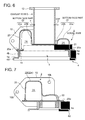
- FIG. 1 is a perspective view of a turbine housing assembly of the present invention.
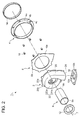
- FIG. 2 is an exploded perspective view of the turbine housing assembly of the present invention.
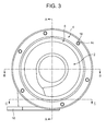
- FIG. 3 is a front view of the turbine housing assembly of the present invention.
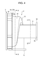
- FIG. 4 is a side view of the turbine housing assembly of the present invention.
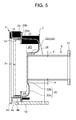
- FIGs. 5 to 9 are cross-sectional views taken along lines A-A to E-E of FIGs. 3 and 4 .
- a turbine housing assembly 1 of the present invention is a turbine housing of a VG (variable geometry) turbocharger including a variable nozzle mechanism, for instance.
- the VG turbocharger includes a variable nozzle mechanism in a turbine housing and controls the amount of exhaust gas flow to be introduced by adjusting the opening degree of the nozzles in the variable nozzle mechanism according to the conditions of the engine. Then, the VG turbocharger controls the supply pressure to the optimum pressure by increasing or decreasing the rotation speed of a turbine wheel by the amount of exhaust gas flow.
- a turbine housing assembly 1 of the present invention is configured as illustrated in FIG. 1 by assembling a plurality of constituent members such as a scroll part 2, a connection part 4, an annular lid part 6, and an exhaust part 8 as illustrated in FIG. 2 . Then, as illustrated in FIG. 1 , a variable nozzle mechanism 3 and a turbine wheel 5 are inserted into the assembled turbine housing assembly 1 from the front side thereof. Further, a bearing housing (not illustrated) for housing a bearing that rotatably supports a rotation shaft of the turbine wheel 5 is connected to the front side of the assembled turbine housing assembly 1.
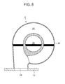
- the scroll part 2 has a bottomed cylindrical shape including a surrounding wall part 20 and a bottom face part 22. Further, as illustrated in FIG. 8 , an exhaust gas flow path 2A is formed into a spiral shape along the surrounding wall part 20 inside the scroll part 2 of a bottomed cylindrical shape, while an exhaust gas outlet 2B is disposed on the bottom face part 22, the exhaust gas outlet 2B having a through hole thereon at a position surrounded by the exhaust gas flow path 2A formed into a spiral shape.
- the bottom face 22a of the exhaust gas flow path 2A of a spiral shape has a shape projecting toward the back face side of the bottom face part 22. Further, a cross-section of the flow path is formed so as to become shallow monotonically in a predetermined turning direction. Accordingly, the back face side of the bottom face part 22 is formed to have an uneven surface, including a recess portion 22b through which the exhaust gas outlet 2B is formed and a projecting portion 22a formed into a projecting shape that surrounds the recess portion 22b.
- a flange portion 20a is formed on an edge of the surrounding wall part 20, the flange portion 20a protruding outward in a direction substantially perpendicular with respect to the surrounding wall part 20. Also, a plurality of positioning portions 20b are formed on the flange portion 20a with equal intervals in the circumferential direction, the positioning portions 20b protruding outward from the flange portion 20a.
- an exhaust gas outlet 24 is formed on the upstream end of the exhaust gas flow path 2A.
- an engine-side flange portion 10 of a flat plate-like shape is connected by, for instance, welding.
- the engine-side flange portion 10 has bolt insertion holes 10b formed thereon so as to be fastened to an exhaust duct (not illustrated) by bolts. Accordingly, exhaust gas having a high temperature discharged from the engine flows through the exhaust duct to be introduced into the exhaust gas flow path 2A, passing through the exhaust gas inlet 24 from an opening 10a of the engine-side flange portion 10.
- the introduced exhaust gas is, after rotating the above described turbine wheel 5, discharged from the exhaust gas outlet 2B.
- the connection part 4 includes a flange portion 4a of an annular and flat plate-like shape and a protruding portion 4b of an annular shape protruding perpendicularly with respect to the flange portion 4a.
- the flange portion 4a has a plurality of bushing insertion holes 4c formed thereon with equal intervals in the circumferential direction of the flange portion 4a. It is configured such that a threaded bushing 16 that has a cylindrical shape and threads formed on its hole is inserted into each of the bushing insertion holes 4c.
- the threaded bushings 16 are used as bolt holes for fastening the above described bearing housing and the connection part 4 by bolts.
- the annular lid part 6 includes a flat plate-like part 6a of an annular shape and positioning portions 6b protruding outward from the flat plate-like part 6a.
- the positioning portions 6b are disposed on the positions corresponding to the positioning portions 20b of the scroll part 2 and the bushing insertion holes 4c of the connection part 4 described above with the same intervals as the above.
- the scroll part 2, the connection part 4, and the annular lid part 6 are each formed by processing a single piece of sheet metal. That is, each of the above is formed by plastic-deforming a flat plate-like piece of sheet metal into a predetermined shape by processes such as bending and pressing, or by partially cutting-off unnecessary portions by processes such as punching. Further, as a material of the scroll part 2, connection part 4, and annular lid part 6, for instance, a heat-resistant steel such as austenite stainless steel may be suitably used.
- the exhaust part 8 is formed into a tubular shape. Further, an end portion 8a of the exhaust part 8 is connected to the recess portion 22b at the back face side of the bottom face part 22 of the scroll part 2 described above by welding for instance, to be in communication with the exhaust gas outlet 2B. Meanwhile, to the other end portion 8b of the exhaust part 8, a muffler-side flange portion 12 including an annular and flat plate-like member is connected by, for instance, welding.
- exhaust gas that has flowed through the exhaust part 8 passes through the muffler-side exhaust duct to be discharged outside of the vehicle from a muffler.
- a gap "a" is formed between the projecting portion 22a and the outer circumferential face of the exhaust part 8 connected to the recess portion 22b of the scroll part 2.
- the gap "a" between the outer circumferential face of the exhaust part 8 and the projecting portion 22a means a distance which separates the outer circumferential face of the exhaust part 8 and the projecting portion 22a in a direction perpendicular to the outer surface of the exhaust part 8.
- the temperature of the exhaust gas flowing into the exhaust part 8 is lower than that of the exhaust gas flowing through the exhaust gas flow path 2A by approximately 100 degrees. Accordingly, with the exhaust part 8 and the scroll part 2 being connected so that the gap "a" is formed between the outer circumferential face of the exhaust part 8 and the projecting portion 22a, it becomes difficult for the exhaust gas having a high temperature and flowing through the exhaust gas flow path 2A to affect the exhaust part 8.
- a material of the exhaust part 8 in accordance with the temperature of the exhaust gas that passes through the exhaust part 8.
- it is possible to form the exhaust part 8 of a material having less heat resistance than that of the scroll part 2 specifically, a stainless material that contains less nickel and is less expensive).
- reinforcement ribs 25 are disposed on the inner circumferential side of the projecting portion 22a of the scroll part 2.
- the reinforcement ribs 25 are connected to the outer circumferential face of the exhaust part 8 by, for instance, welding.
- a plurality of (for instance, three) reinforcement ribs 25 are disposed with equal intervals in the circumferential direction.
- the reinforcement ribs 25 of the present embodiment are provided integrally with the projecting portion 22a of the scroll part 2.
- the present invention is not limited to this.
- the reinforcement ribs 25 may be provided integrally with the exhaust part 8 and connected to the inner circumferential side of the projecting portion 22a.
- the reinforcement ribs 25 may be provided separately from the scroll part 2 and the exhaust part 8, and connected to the inner circumferential side of the projecting portion 22a and the outer circumferential face of the exhaust part 8.
- a ring member 14 of an annular shape is inserted to be fitted into the connection part 4 from the front side thereof.
- the ring member 14 is inserted to and fitted at a position where it contacts the annular lid part 6.
- the variable nozzle mechanism 3 is inserted into the inner circumferential side of the ring member 14.
- a turbine housing is broken down into modules such as the scroll part 2 inside which the exhaust gas flow path of a spiral shape is formed and the exhaust part 8 of a tubular shape, the scroll part 2 being formed by processing a single piece of sheet metal.
- the recess portion 20b of the scroll part 2 and the end portion 8a of the exhaust part 8 are connected to each other in the turbine axial direction, so that the exhaust part 8 is brought into communication with the exhaust gas outlet 2B of the scroll part 2 in a state where the gap "a" is formed between the outer circumferential face of the exhaust part 8 and the projecting portion 20a of the scroll part 2.
- the scroll part 2 being formed by processing a single piece of sheet metal, it is possible to reduce the heat capacity and weight of the turbine housing. Also, since the scroll part 2 is formed by processing a single piece of sheet metal, its manufacture is facilitated.
- connection part 4 is formed by processing a single piece of sheet metal and includes a separate body separate from the scroll part 2. Also, the scroll part 2 and the connection part 4 are connected to each other in the turbine axial direction via the annular lid part 6 that is orthogonal to the turbine axial direction.
- each constituent member of the turbine housing assembly 1 of the present invention into a simple shape, thereby facilitating manufacture of each constituent member.
- the scroll part 2 and the connection part 4 are connected in the turbine axial direction via the annular lid part 6 orthogonal to the turbine axial direction line 7, the constituent members such as the connection part 4, the annular lid part 6, the scroll part 2, and the exhaust part 8 are all connected in the turbine axial direction. As a result, the assembling property of the turbine housing assembly 1 is improved.
- a turbine housing is broken down into modules such as the scroll part 2 inside which the exhaust gas flow path 2A of a spiral shape is formed, the exhaust part 8 of a tubular shape, and the connection part 4 connectable to a bearing housing, it is possible to configure the turbine housing assembly 1 of the present invention as an assembly of a plurality of standardized constituent modules. As a result, it is possible to facilitate manufacture of a turbine housing.
- connection part 4 is formed by processing a single piece of sheet metal as well as the scroll part 2, it is possible to reduce the heat capacity and weight of the turbine housing. Also, since the connection part 4 is formed by processing a single piece of sheet metal, its manufacture is facilitated.
- connection part 4 of a stainless material having lower heat resistance than that of the scroll part 2, i.e., a less expensive stainless material containing less nickel than the scroll part 2. As a result, it is possible to reduce the cost of the turbine housing compared to the case where a whole turbine housing is formed of a single material.
- the annular lid part 6 since the annular lid part 6 has a separate body separate from the scroll part 2 and the connection part 4, it is possible to form each constituent member such as the scroll part 2, the connection part 4, and the annular lid part 6 into a simple shape, thereby facilitating the manufacture of each constituent member. Also at this time, forming the annular lid part 6 by processing a single piece of sheet metal also contributes to reduction of the weight and heat capacity of the turbine housing.
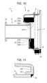
- FIG. 10 is a cross-sectional view of a turbine housing assembly of another embodiment of the present invention.
- the scroll part 2 of the present invention may include a fit-in portion 22c formed on the bottom face part 22, the fit-in portion 22c being formed by bending the bottom face part 22 around the exhaust gas outlet 2B toward the back face side so that the end portion 8a of the exhaust part 8 can be inserted and fitted therein.
- a fit-in portion 22c it is possible to insert and fit the end portion 8a of the exhaust part 8 into the fit-in portion 22c to connect the end portion 8a to the inner circumferential side of the fit-in portion 22c by a fillet weld 23 as illustrated in FIG. 11 , for instance.
- a fillet weld 23 as illustrated in FIG. 11
- the present invention can be suitably used as a turbine housing assembly for a turbocharger, preferably a turbine housing assembly for a VG turbocharger to be mounted on a vehicle.
Landscapes
- Engineering & Computer Science (AREA)
- Mechanical Engineering (AREA)
- General Engineering & Computer Science (AREA)
- Supercharger (AREA)
Applications Claiming Priority (2)
| Application Number | Priority Date | Filing Date | Title |
|---|---|---|---|
| JP2012068210A JP5986767B2 (ja) | 2012-03-23 | 2012-03-23 | タービンハウジングアセンブリ |
| PCT/JP2013/058396 WO2013141380A1 (ja) | 2012-03-23 | 2013-03-22 | タービンハウジングアセンブリ |
Publications (3)
| Publication Number | Publication Date |
|---|---|
| EP2829702A1 true EP2829702A1 (de) | 2015-01-28 |
| EP2829702A4 EP2829702A4 (de) | 2016-06-22 |
| EP2829702B1 EP2829702B1 (de) | 2020-02-19 |
Family
ID=49222828
Family Applications (1)
| Application Number | Title | Priority Date | Filing Date |
|---|---|---|---|
| EP13764393.8A Active EP2829702B1 (de) | 2012-03-23 | 2013-03-22 | Turbinengehäuseanordnung |
Country Status (5)
| Country | Link |
|---|---|
| US (1) | US9708932B2 (de) |
| EP (1) | EP2829702B1 (de) |
| JP (1) | JP5986767B2 (de) |
| CN (1) | CN104379898B (de) |
| WO (1) | WO2013141380A1 (de) |
Families Citing this family (13)
| Publication number | Priority date | Publication date | Assignee | Title |
|---|---|---|---|---|
| WO2015097890A1 (ja) | 2013-12-27 | 2015-07-02 | 三菱重工業株式会社 | タービンハウジング |
| JP2015203398A (ja) * | 2014-04-16 | 2015-11-16 | カルソニックカンセイ株式会社 | ターボチャージャ |
| JP2015214967A (ja) * | 2014-04-22 | 2015-12-03 | カルソニックカンセイ株式会社 | ターボチャージャ |
| US10519806B2 (en) * | 2015-11-06 | 2019-12-31 | Calsonic Kansei Corporation | Turbine housing |
| JP6542640B2 (ja) * | 2015-11-06 | 2019-07-10 | カルソニックカンセイ株式会社 | タービンハウジング |
| CN105370625A (zh) * | 2015-11-27 | 2016-03-02 | 无锡蠡湖增压技术股份有限公司 | 一种冷加工的压气机壳 |
| US10472988B2 (en) | 2017-01-30 | 2019-11-12 | Garrett Transportation I Inc. | Sheet metal turbine housing and related turbocharger systems |
| US10494955B2 (en) | 2017-01-30 | 2019-12-03 | Garrett Transportation I Inc. | Sheet metal turbine housing with containment dampers |
| US10436069B2 (en) * | 2017-01-30 | 2019-10-08 | Garrett Transportation I Inc. | Sheet metal turbine housing with biaxial volute configuration |
| US10544703B2 (en) | 2017-01-30 | 2020-01-28 | Garrett Transportation I Inc. | Sheet metal turbine housing with cast core |
| US10690144B2 (en) | 2017-06-27 | 2020-06-23 | Garrett Transportation I Inc. | Compressor housings and fabrication methods |
| US11136997B2 (en) * | 2019-07-23 | 2021-10-05 | Ford Global Technologies, Llc | Methods and systems for a compressor housing |
| US11732729B2 (en) | 2021-01-26 | 2023-08-22 | Garrett Transportation I Inc | Sheet metal turbine housing |
Family Cites Families (14)
| Publication number | Priority date | Publication date | Assignee | Title |
|---|---|---|---|---|
| JPS61132800A (ja) | 1984-11-29 | 1986-06-20 | Mitsubishi Heavy Ind Ltd | 過給機用コンプレツサ−ハウジング及びその製造方法 |
| US4850797A (en) * | 1988-01-21 | 1989-07-25 | Benson Steven R | Double chambered turbine housing and seal |
| DE10061846B4 (de) * | 2000-12-12 | 2004-09-09 | Daimlerchrysler Ag | Abgasturbolader für eine Brennkraftmaschine |
| DE10218436C1 (de) | 2002-04-25 | 2003-08-14 | Benteler Automobiltechnik Gmbh | Abgasturbine für einen Turbolader |
| GB0223756D0 (en) * | 2002-10-14 | 2002-11-20 | Holset Engineering Co | Compressor |
| EP1460237B1 (de) * | 2003-03-19 | 2010-05-12 | ABB Turbo Systems AG | Abgasturbinengehäuse |
| DE10325649B4 (de) * | 2003-06-06 | 2014-10-23 | Ihi Charging Systems International Gmbh | Abgasturbine für einen Abgasturbolader |
| DE10352960B4 (de) * | 2003-11-13 | 2006-06-14 | Benteler Automobiltechnik Gmbh | Gehäuseanordnung für den Turbolader einer Brennkraftmaschine |
| DE102004039477B4 (de) | 2004-08-14 | 2015-01-08 | Ihi Charging Systems International Gmbh | Turbinengehäuse für einen Abgasturbolader |
| JP4634319B2 (ja) * | 2006-02-23 | 2011-02-16 | アイシン高丘株式会社 | タービンハウジング |
| JP4835330B2 (ja) * | 2006-08-31 | 2011-12-14 | トヨタ自動車株式会社 | タービンハウジング |
| WO2010052911A1 (ja) | 2008-11-05 | 2010-05-14 | 株式会社Ihi | ターボチャージャ |
| US8372335B2 (en) * | 2010-01-14 | 2013-02-12 | Honeywell International Inc. | Austenitic ductile cast iron |
| JP5769407B2 (ja) * | 2010-02-01 | 2015-08-26 | 三菱重工業株式会社 | 板金タービンハウジング |
-
2012
- 2012-03-23 JP JP2012068210A patent/JP5986767B2/ja active Active
-
2013
- 2013-03-22 US US14/386,425 patent/US9708932B2/en active Active
- 2013-03-22 EP EP13764393.8A patent/EP2829702B1/de active Active
- 2013-03-22 WO PCT/JP2013/058396 patent/WO2013141380A1/ja not_active Ceased
- 2013-03-22 CN CN201380015195.0A patent/CN104379898B/zh active Active
Also Published As
| Publication number | Publication date |
|---|---|
| CN104379898B (zh) | 2018-10-12 |
| EP2829702A4 (de) | 2016-06-22 |
| US9708932B2 (en) | 2017-07-18 |
| WO2013141380A1 (ja) | 2013-09-26 |
| JP2013199864A (ja) | 2013-10-03 |
| EP2829702B1 (de) | 2020-02-19 |
| US20150044034A1 (en) | 2015-02-12 |
| CN104379898A (zh) | 2015-02-25 |
| JP5986767B2 (ja) | 2016-09-06 |
Similar Documents
| Publication | Publication Date | Title |
|---|---|---|
| US9835165B2 (en) | Turbine housing assembly and manufacturing method of turbine housing assembly | |
| EP2829702B1 (de) | Turbinengehäuseanordnung | |
| US7862295B2 (en) | Device for guiding a stream of air entering a combustion chamber of a turbomachine | |
| US10041389B2 (en) | Valve housing and valve | |
| US20110120124A1 (en) | Exhaust gas turbocharger | |
| JP2008025575A (ja) | ターボ機械用のディフューザ/ガイドベーンアセンブリ | |
| EP2531701B1 (de) | Turbolader und gehäuse für ein turboladerrad | |
| JP2008025579A5 (de) | ||
| US20160003259A1 (en) | Turbocharger | |
| US20140196978A1 (en) | Silencer and method for manufacturing the same | |
| JP5242107B2 (ja) | 環状のターボ機械燃焼室 | |
| EP3085919A1 (de) | Variable düseneinheit turbolader mit variabler geometrie | |
| US11484934B2 (en) | Manufacturing method of casing | |
| EP3382209B1 (de) | Zentrifugalverdichter und superlader | |
| EP2821618B1 (de) | Turbolader-turbinenrotor und herstellungsverfahren dafür | |
| US9963983B2 (en) | Turbocharger | |
| EP3473354A1 (de) | Hohles produkt und verfahren zur herstellung des produkts | |
| JP6320281B2 (ja) | タービンハウジング | |
| JPWO2015097890A1 (ja) | タービンハウジング | |
| US10532500B2 (en) | Hollow product and method of making the product |
Legal Events
| Date | Code | Title | Description |
|---|---|---|---|
| PUAI | Public reference made under article 153(3) epc to a published international application that has entered the european phase |
Free format text: ORIGINAL CODE: 0009012 |
|
| 17P | Request for examination filed |
Effective date: 20140922 |
|
| AK | Designated contracting states |
Kind code of ref document: A1 Designated state(s): AL AT BE BG CH CY CZ DE DK EE ES FI FR GB GR HR HU IE IS IT LI LT LU LV MC MK MT NL NO PL PT RO RS SE SI SK SM TR |
|
| AX | Request for extension of the european patent |
Extension state: BA ME |
|
| DAX | Request for extension of the european patent (deleted) | ||
| RA4 | Supplementary search report drawn up and despatched (corrected) |
Effective date: 20160524 |
|
| RIC1 | Information provided on ipc code assigned before grant |
Ipc: F02C 6/12 20060101ALI20160518BHEP Ipc: F02B 39/00 20060101AFI20160518BHEP Ipc: F01D 9/02 20060101ALI20160518BHEP |
|
| RAP1 | Party data changed (applicant data changed or rights of an application transferred) |
Owner name: MITSUBISHI HEAVY INDUSTRIES ENGINE & TURBOCHARGER, |
|
| GRAP | Despatch of communication of intention to grant a patent |
Free format text: ORIGINAL CODE: EPIDOSNIGR1 |
|
| STAA | Information on the status of an ep patent application or granted ep patent |
Free format text: STATUS: GRANT OF PATENT IS INTENDED |
|
| INTG | Intention to grant announced |
Effective date: 20191010 |
|
| GRAS | Grant fee paid |
Free format text: ORIGINAL CODE: EPIDOSNIGR3 |
|
| GRAA | (expected) grant |
Free format text: ORIGINAL CODE: 0009210 |
|
| STAA | Information on the status of an ep patent application or granted ep patent |
Free format text: STATUS: THE PATENT HAS BEEN GRANTED |
|
| AK | Designated contracting states |
Kind code of ref document: B1 Designated state(s): AL AT BE BG CH CY CZ DE DK EE ES FI FR GB GR HR HU IE IS IT LI LT LU LV MC MK MT NL NO PL PT RO RS SE SI SK SM TR |
|
| REG | Reference to a national code |
Ref country code: GB Ref legal event code: FG4D |
|
| REG | Reference to a national code |
Ref country code: CH Ref legal event code: EP |
|
| REG | Reference to a national code |
Ref country code: DE Ref legal event code: R096 Ref document number: 602013066136 Country of ref document: DE |
|
| REG | Reference to a national code |
Ref country code: AT Ref legal event code: REF Ref document number: 1235223 Country of ref document: AT Kind code of ref document: T Effective date: 20200315 |
|
| REG | Reference to a national code |
Ref country code: IE Ref legal event code: FG4D |
|
| REG | Reference to a national code |
Ref country code: NL Ref legal event code: MP Effective date: 20200219 |
|
| PG25 | Lapsed in a contracting state [announced via postgrant information from national office to epo] |
Ref country code: NO Free format text: LAPSE BECAUSE OF FAILURE TO SUBMIT A TRANSLATION OF THE DESCRIPTION OR TO PAY THE FEE WITHIN THE PRESCRIBED TIME-LIMIT Effective date: 20200519 Ref country code: FI Free format text: LAPSE BECAUSE OF FAILURE TO SUBMIT A TRANSLATION OF THE DESCRIPTION OR TO PAY THE FEE WITHIN THE PRESCRIBED TIME-LIMIT Effective date: 20200219 Ref country code: RS Free format text: LAPSE BECAUSE OF FAILURE TO SUBMIT A TRANSLATION OF THE DESCRIPTION OR TO PAY THE FEE WITHIN THE PRESCRIBED TIME-LIMIT Effective date: 20200219 |
|
| REG | Reference to a national code |
Ref country code: LT Ref legal event code: MG4D |
|
| PG25 | Lapsed in a contracting state [announced via postgrant information from national office to epo] |
Ref country code: BG Free format text: LAPSE BECAUSE OF FAILURE TO SUBMIT A TRANSLATION OF THE DESCRIPTION OR TO PAY THE FEE WITHIN THE PRESCRIBED TIME-LIMIT Effective date: 20200519 Ref country code: GR Free format text: LAPSE BECAUSE OF FAILURE TO SUBMIT A TRANSLATION OF THE DESCRIPTION OR TO PAY THE FEE WITHIN THE PRESCRIBED TIME-LIMIT Effective date: 20200520 Ref country code: SE Free format text: LAPSE BECAUSE OF FAILURE TO SUBMIT A TRANSLATION OF THE DESCRIPTION OR TO PAY THE FEE WITHIN THE PRESCRIBED TIME-LIMIT Effective date: 20200219 Ref country code: IS Free format text: LAPSE BECAUSE OF FAILURE TO SUBMIT A TRANSLATION OF THE DESCRIPTION OR TO PAY THE FEE WITHIN THE PRESCRIBED TIME-LIMIT Effective date: 20200619 Ref country code: LV Free format text: LAPSE BECAUSE OF FAILURE TO SUBMIT A TRANSLATION OF THE DESCRIPTION OR TO PAY THE FEE WITHIN THE PRESCRIBED TIME-LIMIT Effective date: 20200219 Ref country code: HR Free format text: LAPSE BECAUSE OF FAILURE TO SUBMIT A TRANSLATION OF THE DESCRIPTION OR TO PAY THE FEE WITHIN THE PRESCRIBED TIME-LIMIT Effective date: 20200219 |
|
| PG25 | Lapsed in a contracting state [announced via postgrant information from national office to epo] |
Ref country code: NL Free format text: LAPSE BECAUSE OF FAILURE TO SUBMIT A TRANSLATION OF THE DESCRIPTION OR TO PAY THE FEE WITHIN THE PRESCRIBED TIME-LIMIT Effective date: 20200219 |
|
| PG25 | Lapsed in a contracting state [announced via postgrant information from national office to epo] |
Ref country code: CZ Free format text: LAPSE BECAUSE OF FAILURE TO SUBMIT A TRANSLATION OF THE DESCRIPTION OR TO PAY THE FEE WITHIN THE PRESCRIBED TIME-LIMIT Effective date: 20200219 Ref country code: SK Free format text: LAPSE BECAUSE OF FAILURE TO SUBMIT A TRANSLATION OF THE DESCRIPTION OR TO PAY THE FEE WITHIN THE PRESCRIBED TIME-LIMIT Effective date: 20200219 Ref country code: DK Free format text: LAPSE BECAUSE OF FAILURE TO SUBMIT A TRANSLATION OF THE DESCRIPTION OR TO PAY THE FEE WITHIN THE PRESCRIBED TIME-LIMIT Effective date: 20200219 Ref country code: PT Free format text: LAPSE BECAUSE OF FAILURE TO SUBMIT A TRANSLATION OF THE DESCRIPTION OR TO PAY THE FEE WITHIN THE PRESCRIBED TIME-LIMIT Effective date: 20200712 Ref country code: SM Free format text: LAPSE BECAUSE OF FAILURE TO SUBMIT A TRANSLATION OF THE DESCRIPTION OR TO PAY THE FEE WITHIN THE PRESCRIBED TIME-LIMIT Effective date: 20200219 Ref country code: EE Free format text: LAPSE BECAUSE OF FAILURE TO SUBMIT A TRANSLATION OF THE DESCRIPTION OR TO PAY THE FEE WITHIN THE PRESCRIBED TIME-LIMIT Effective date: 20200219 Ref country code: RO Free format text: LAPSE BECAUSE OF FAILURE TO SUBMIT A TRANSLATION OF THE DESCRIPTION OR TO PAY THE FEE WITHIN THE PRESCRIBED TIME-LIMIT Effective date: 20200219 Ref country code: ES Free format text: LAPSE BECAUSE OF FAILURE TO SUBMIT A TRANSLATION OF THE DESCRIPTION OR TO PAY THE FEE WITHIN THE PRESCRIBED TIME-LIMIT Effective date: 20200219 Ref country code: LT Free format text: LAPSE BECAUSE OF FAILURE TO SUBMIT A TRANSLATION OF THE DESCRIPTION OR TO PAY THE FEE WITHIN THE PRESCRIBED TIME-LIMIT Effective date: 20200219 |
|
| REG | Reference to a national code |
Ref country code: CH Ref legal event code: PL |
|
| REG | Reference to a national code |
Ref country code: AT Ref legal event code: MK05 Ref document number: 1235223 Country of ref document: AT Kind code of ref document: T Effective date: 20200219 |
|
| REG | Reference to a national code |
Ref country code: DE Ref legal event code: R097 Ref document number: 602013066136 Country of ref document: DE |
|
| PG25 | Lapsed in a contracting state [announced via postgrant information from national office to epo] |
Ref country code: MC Free format text: LAPSE BECAUSE OF FAILURE TO SUBMIT A TRANSLATION OF THE DESCRIPTION OR TO PAY THE FEE WITHIN THE PRESCRIBED TIME-LIMIT Effective date: 20200219 |
|
| REG | Reference to a national code |
Ref country code: BE Ref legal event code: MM Effective date: 20200331 |
|
| PLBE | No opposition filed within time limit |
Free format text: ORIGINAL CODE: 0009261 |
|
| STAA | Information on the status of an ep patent application or granted ep patent |
Free format text: STATUS: NO OPPOSITION FILED WITHIN TIME LIMIT |
|
| PG25 | Lapsed in a contracting state [announced via postgrant information from national office to epo] |
Ref country code: LU Free format text: LAPSE BECAUSE OF NON-PAYMENT OF DUE FEES Effective date: 20200322 |
|
| 26N | No opposition filed |
Effective date: 20201120 |
|
| PG25 | Lapsed in a contracting state [announced via postgrant information from national office to epo] |
Ref country code: AT Free format text: LAPSE BECAUSE OF FAILURE TO SUBMIT A TRANSLATION OF THE DESCRIPTION OR TO PAY THE FEE WITHIN THE PRESCRIBED TIME-LIMIT Effective date: 20200219 Ref country code: IT Free format text: LAPSE BECAUSE OF FAILURE TO SUBMIT A TRANSLATION OF THE DESCRIPTION OR TO PAY THE FEE WITHIN THE PRESCRIBED TIME-LIMIT Effective date: 20200219 Ref country code: CH Free format text: LAPSE BECAUSE OF NON-PAYMENT OF DUE FEES Effective date: 20200331 Ref country code: IE Free format text: LAPSE BECAUSE OF NON-PAYMENT OF DUE FEES Effective date: 20200322 Ref country code: LI Free format text: LAPSE BECAUSE OF NON-PAYMENT OF DUE FEES Effective date: 20200331 |
|
| PG25 | Lapsed in a contracting state [announced via postgrant information from national office to epo] |
Ref country code: PL Free format text: LAPSE BECAUSE OF FAILURE TO SUBMIT A TRANSLATION OF THE DESCRIPTION OR TO PAY THE FEE WITHIN THE PRESCRIBED TIME-LIMIT Effective date: 20200219 Ref country code: SI Free format text: LAPSE BECAUSE OF FAILURE TO SUBMIT A TRANSLATION OF THE DESCRIPTION OR TO PAY THE FEE WITHIN THE PRESCRIBED TIME-LIMIT Effective date: 20200219 Ref country code: BE Free format text: LAPSE BECAUSE OF NON-PAYMENT OF DUE FEES Effective date: 20200331 |
|
| PGFP | Annual fee paid to national office [announced via postgrant information from national office to epo] |
Ref country code: FR Payment date: 20210210 Year of fee payment: 9 |
|
| PGFP | Annual fee paid to national office [announced via postgrant information from national office to epo] |
Ref country code: GB Payment date: 20210310 Year of fee payment: 9 |
|
| PG25 | Lapsed in a contracting state [announced via postgrant information from national office to epo] |
Ref country code: TR Free format text: LAPSE BECAUSE OF FAILURE TO SUBMIT A TRANSLATION OF THE DESCRIPTION OR TO PAY THE FEE WITHIN THE PRESCRIBED TIME-LIMIT Effective date: 20200219 Ref country code: MT Free format text: LAPSE BECAUSE OF FAILURE TO SUBMIT A TRANSLATION OF THE DESCRIPTION OR TO PAY THE FEE WITHIN THE PRESCRIBED TIME-LIMIT Effective date: 20200219 Ref country code: CY Free format text: LAPSE BECAUSE OF FAILURE TO SUBMIT A TRANSLATION OF THE DESCRIPTION OR TO PAY THE FEE WITHIN THE PRESCRIBED TIME-LIMIT Effective date: 20200219 |
|
| PG25 | Lapsed in a contracting state [announced via postgrant information from national office to epo] |
Ref country code: MK Free format text: LAPSE BECAUSE OF FAILURE TO SUBMIT A TRANSLATION OF THE DESCRIPTION OR TO PAY THE FEE WITHIN THE PRESCRIBED TIME-LIMIT Effective date: 20200219 Ref country code: AL Free format text: LAPSE BECAUSE OF FAILURE TO SUBMIT A TRANSLATION OF THE DESCRIPTION OR TO PAY THE FEE WITHIN THE PRESCRIBED TIME-LIMIT Effective date: 20200219 |
|
| GBPC | Gb: european patent ceased through non-payment of renewal fee |
Effective date: 20220322 |
|
| PG25 | Lapsed in a contracting state [announced via postgrant information from national office to epo] |
Ref country code: GB Free format text: LAPSE BECAUSE OF NON-PAYMENT OF DUE FEES Effective date: 20220322 Ref country code: FR Free format text: LAPSE BECAUSE OF NON-PAYMENT OF DUE FEES Effective date: 20220331 |
|
| PGFP | Annual fee paid to national office [announced via postgrant information from national office to epo] |
Ref country code: DE Payment date: 20250128 Year of fee payment: 13 |