EP2829656B1 - Dispositif destiné à l'installation guidée par amortissement d'oscillations d'une unité de capteur ou de commutation sur un rail de roulement - Google Patents
Dispositif destiné à l'installation guidée par amortissement d'oscillations d'une unité de capteur ou de commutation sur un rail de roulement Download PDFInfo
- Publication number
- EP2829656B1 EP2829656B1 EP14177600.5A EP14177600A EP2829656B1 EP 2829656 B1 EP2829656 B1 EP 2829656B1 EP 14177600 A EP14177600 A EP 14177600A EP 2829656 B1 EP2829656 B1 EP 2829656B1
- Authority
- EP
- European Patent Office
- Prior art keywords
- fastening element
- fastening
- rail
- switching
- sensor unit
- Prior art date
- Legal status (The legal status is an assumption and is not a legal conclusion. Google has not performed a legal analysis and makes no representation as to the accuracy of the status listed.)
- Active
Links
Images
Classifications
-
- E—FIXED CONSTRUCTIONS
- E01—CONSTRUCTION OF ROADS, RAILWAYS, OR BRIDGES
- E01B—PERMANENT WAY; PERMANENT-WAY TOOLS; MACHINES FOR MAKING RAILWAYS OF ALL KINDS
- E01B26/00—Tracks or track components not covered by any one of the preceding groups
-
- F—MECHANICAL ENGINEERING; LIGHTING; HEATING; WEAPONS; BLASTING
- F16—ENGINEERING ELEMENTS AND UNITS; GENERAL MEASURES FOR PRODUCING AND MAINTAINING EFFECTIVE FUNCTIONING OF MACHINES OR INSTALLATIONS; THERMAL INSULATION IN GENERAL
- F16F—SPRINGS; SHOCK-ABSORBERS; MEANS FOR DAMPING VIBRATION
- F16F1/00—Springs
- F16F1/36—Springs made of rubber or other material having high internal friction, e.g. thermoplastic elastomers
- F16F1/38—Springs made of rubber or other material having high internal friction, e.g. thermoplastic elastomers with a sleeve of elastic material between a rigid outer sleeve and a rigid inner sleeve or pin, i.e. bushing-type
-
- F—MECHANICAL ENGINEERING; LIGHTING; HEATING; WEAPONS; BLASTING
- F16—ENGINEERING ELEMENTS AND UNITS; GENERAL MEASURES FOR PRODUCING AND MAINTAINING EFFECTIVE FUNCTIONING OF MACHINES OR INSTALLATIONS; THERMAL INSULATION IN GENERAL
- F16F—SPRINGS; SHOCK-ABSORBERS; MEANS FOR DAMPING VIBRATION
- F16F15/00—Suppression of vibrations in systems; Means or arrangements for avoiding or reducing out-of-balance forces, e.g. due to motion
- F16F15/02—Suppression of vibrations of non-rotating, e.g. reciprocating systems; Suppression of vibrations of rotating systems by use of members not moving with the rotating systems
- F16F15/04—Suppression of vibrations of non-rotating, e.g. reciprocating systems; Suppression of vibrations of rotating systems by use of members not moving with the rotating systems using elastic means
- F16F15/08—Suppression of vibrations of non-rotating, e.g. reciprocating systems; Suppression of vibrations of rotating systems by use of members not moving with the rotating systems using elastic means with rubber springs ; with springs made of rubber and metal
-
- B—PERFORMING OPERATIONS; TRANSPORTING
- B61—RAILWAYS
- B61L—GUIDING RAILWAY TRAFFIC; ENSURING THE SAFETY OF RAILWAY TRAFFIC
- B61L1/00—Devices along the route controlled by interaction with the vehicle or train
- B61L1/02—Electric devices associated with track, e.g. rail contacts
-
- B—PERFORMING OPERATIONS; TRANSPORTING
- B61—RAILWAYS
- B61L—GUIDING RAILWAY TRAFFIC; ENSURING THE SAFETY OF RAILWAY TRAFFIC
- B61L1/00—Devices along the route controlled by interaction with the vehicle or train
- B61L1/16—Devices for counting axles; Devices for counting vehicles
-
- B—PERFORMING OPERATIONS; TRANSPORTING
- B61—RAILWAYS
- B61L—GUIDING RAILWAY TRAFFIC; ENSURING THE SAFETY OF RAILWAY TRAFFIC
- B61L3/00—Devices along the route for controlling devices on the vehicle or train, e.g. to release brake or to operate a warning signal
- B61L3/02—Devices along the route for controlling devices on the vehicle or train, e.g. to release brake or to operate a warning signal at selected places along the route, e.g. intermittent control simultaneous mechanical and electrical control
- B61L3/08—Devices along the route for controlling devices on the vehicle or train, e.g. to release brake or to operate a warning signal at selected places along the route, e.g. intermittent control simultaneous mechanical and electrical control controlling electrically
- B61L3/12—Devices along the route for controlling devices on the vehicle or train, e.g. to release brake or to operate a warning signal at selected places along the route, e.g. intermittent control simultaneous mechanical and electrical control controlling electrically using magnetic or electrostatic induction; using radio waves
- B61L3/126—Constructional details
Definitions
- the present invention relates to a device for the vibration-damped attachment of a switching or sensor unit to a running rail.
- switching or sensor unit may in particular mean a rail switch for train location, direction detection, speed measurement, axle counting or the like, which in the following will only be referred to as "unit".
- a fastening device of the type mentioned shows, for example, the document DE 3816791 A1 , It discloses a device for fastening a housing to a running rail whose housing is fastened via a bracket to the rail web of a running rail. The rail was pierced to attach a fastener and then connected by a screw mechanism to the console. The attachment of the housing to the console via two height-adjustable threaded bolt. Each threaded bolt has an internal thread for receiving a mounting screw Mistake. The threaded bolts are set via threaded inserts in the console threaded inserts with screw-clamping areas in the console. To adjust the height of the housing, the fastening screws are loosened, then the threaded bolts screwed deeper into the console and then tightened the mounting screws again.
- the fastening device DE 3816791 A1 In addition to its complexity by the multi-part design and the complex assembly, considerable disadvantages and sets the housing to be fastened to the running rail, in particular when passing a rail vehicle, considerable mechanical vibrations.
- CH332 699 A discloses a device for vibration-damped mounting a sensor unit according to the preamble of claim 1.
- the previous fastening methods suggest that particularly vulnerable components such as electronic components and the like with an elastic mass to coat. This is production-consuming and yet does not eliminate the burden of other fracture-prone components of the wheel sensor.
- additional design measures are necessary because the sheath claimed additional volume.
- the volume of construction is limited by the application, namely the attachment below the functional surface of the rail, it is necessary to use the available space as efficiently as possible.
- the functional surface is defined upwards by the horizontal running line of the periphery of the wheel flange of a rail vehicle wheel.
- a fastening device with the features of claim 1. Accordingly, it is provided that a device for vibration-damped mounting of a switching or sensor unit on a running rail has a first fastening element which can be fastened to the running rail, a second fastening element for retaining receptacle the switching or sensor unit, and a damping element, wherein the first and the second fastening element are interconnected by means of the damping element arranged between them.
- the first fastening element which serves for fastening to the running rail, can be connected to the rail element in any manner known per se by means of a clamp, a screw connection, or another conventional but detachable method.
- a clamp a screw connection
- a weld a riveting, or a bond
- these connection methods are disadvantageous in that they are not or only with great effort solvable again, which would pose a problem in a preparation of the ballast bed as the switching or sensor units must then be removed regularly.
- a parenthesis is already out of the document AT 394172 B known, which is received only on the clamping mechanism of a jaw, which can be placed on the side of the rail on the rail and clamped by a trained under the rail tie rod against at least one attacking on the other side of the rail foot chuck.
- a staple offers the advantage that it is easy and above all to install quickly and can be subsequently added with little effort
- a gland in practice for fixed equipment is common and easy to install after drilling through the rail web and also subsequently solvable. Since welding and riveting are cohesive processes, they offer the advantage of high strength, but can only be removed again with great effort. Bonding offers the advantage of fast manufacturability.
- the second fastening element engages around at least a part of the first fastening element.
- a flange is provided on the first fastening element at the end of the rail facing the end, which rests in the installed state on the web of the running rail.
- the flange is usually dimensioned in cooperation with a screw connection so that a sufficient restoring moment is achieved for the load case and a permanent connection is ensured.
- a welding or gluing of the flange with the web of the rail is conceivable.
- the damping element consists essentially of an elastic polymer.
- an elastic polymer is inexpensive and easy to manufacture.
- An elasticity optimized for the load case is chosen so that it compensates for the mechanical vibrations induced by the rail vehicle and keeps it away from the unit.
- a polymer is readily moldable in the manufacturing state and usually adhesive until polymerization, whereby the two fasteners can be assembled by the damping element before mounting to the rail to a single assembly. This in turn offers the advantage of simplified handling and assembly.
- a Shore hardness of 80 could be used.
- the damping element is formed as a damping material layer on the lateral surface of the first fastening element is.
- a corresponding layer is easy to apply and to manufacture.
- a damping material strip which is executed on its surface with an adhesive layer and could be glued on site to the first fastener before a larger diameter than the outer diameter of the first fastener executed second fastener is adhered to the first fastener.
- Another production variant could make use of the good plasticity of the polymer in the not yet polymerized state in order to form a damping layer which is free of voids and bubbles and thus achieves the most homogeneous possible damping behavior.
- the first fastening element and the second fastening element is sleeve-shaped.
- a rectangular expression would be conceivable; However, preference is given to a cylindrical shape for strength and material saving reasons.
- the invention also provides that the first fastener bolt-shaped and the second fastener is sleeve-shaped.
- the first fastening element and the second fastening element are arranged one inside the other about a common axis of symmetry, and that the damping element between the outside of the first fastening element and the inside of the second fastening element is arranged. As a result, this results in a coaxial arrangement of the two fastening elements to each other, wherein the damping element or the damping layer is also at least partially coaxially therebetween.
- a removable device is to be preferred. Accordingly, a preferred embodiment is provided in which the first fastening element by means of a screw or a bolt which (r) the sleeve of the first fastening element and a corresponding bore in the web of the running rail penetrates axially and can be fastened to the running rail.
- first fastening element and the second fastening element are cylindrical. These cylindrical components are easy to manufacture and so at least for the second fastener and the production of a corresponding sleeve, a pressing or deep-drawing process is conceivable.
- a thickening is formed at the ends of the second fastening element. This avoids tilting during assembly and achieves, for example, faster assembly without the aid of lubricants. Furthermore, the advantageous positioning of the second fastening element within the housing is thereby achieved, which is then fixed by casting with a matched in their mechanical properties to the load case, the passing of one or more rail vehicles, potting compound.
- sealing collar likewise of different diameter, is mounted on the thickenings of the second fastening element (outer diameter B and G).
- the second fastening element to the first fastening element in the context of the elasticity of the damping element is arranged horizontally, vertically and laterally freely movable.
- the device with the unit is connected such that it is arranged laterally from the running rail and below the line of movement of the wheel flange of a vehicle rail driving the vehicle and spaced from this line of movement.
- At least one elastic sealing disc is arranged between the flange and the switching or sensor unit.
- the flange is dimensioned such that it serves as an abutment for the sealing washer and additionally compensates for vibrations in cooperation with the elastic sealing washer in the direction of the axis of symmetry.
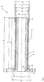
- FIG. 1 shows a cross section of an embodiment of a device 1 according to the invention.
- the fastening device 1 has a first fastening element 2, to which the rail 3 end facing a flange 8 is formed.
- the flange has a height I for a given diameter A and has a transition region 10 between flange 8 and outer diameter D of the first fastening element 2.
- an elastic, polymeric damping element 6 is arranged coaxial between the first fastening element 2 and the second fastening element 4. Also, this damping element 6 surrounds the fastening element 2 over its entire axial length. In principle, it would also be conceivable to mount the damping element 6 only in longitudinal or transverse strips on the lateral surface of the sleeve of the fastening element 2. However, a melting of the damping layer to form the damping element 6 is to give preference, resulting in a continuous functional adhesive surface of length K. The functional height of the damping element 6 results from the difference between the diameters D and E. As shown, the functional adhesive surface of the length K can also extend over the entire length J of the second fastening element 4.
- the difference between the dimensions L and M results in a defined free space lying in front of the transition region 10 to the flange 8.
- the radius of the transition region 10 is dimensioned such that, depending on the metal or metal alloy selected for the first fastening element 2, cracking in the transition region 10 is precluded.
- the materials used may be of non-metallic origin and may be formed of a non-ferromagnetic material in order to exclude interference between the switching or sensor unit 22 with the rail vehicle to be detected.
- the damping element 6 and the resulting between the outer diameters D and E thickness of the damping element 6 is selected such that for the load case in the context of elasticity of the damping element 6 horizontal, vertical and lateral clearance is ensured.
- the second fastening element has at its the flange 8 and the side of the rail 3 facing side a thickening 12 which is adapted to receive the housing of a switching or sensor unit 22.
- This first thickening 12 is defined by the outer diameter B and is larger than the outer diameter G of the flange facing away from thickening 14 of the second fastening element 4 in the illustrated embodiment.
- This realization achieved by the different design of the outer diameter B and G, a determination of the preferred mounting sequence.
- tongue and groove elements are conceivable which save additional fastening materials.
- the outer surface of the second fastening element 4 is defined by the outer diameter F and the inner surface of the second fastening element 4 by the inner diameter E.
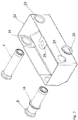
- FIG. 2 shows a perspective view of the embodiment according to FIG. 1 with a housing of a switching or sensor unit.
- the flange 8 of the first fastening element 2 and the second fastening element 4 can be seen, which are joined together to form a common assembly.
- the perspective shows elastic sealing discs 16 and 20 of different diameters, which in cooperation with the flange 8 or the first or second fastening element 2 and 4, and the housing of the switching or sensor unit 22 in coaxial and partly also in the radial direction oscillations additionally compensate.
- a housing bore 28 which, in cooperation with the thickening 12, is adapted to receive the housing of a switching or sensor unit 22.
- a cable bushing 26 serves as a receptacle for the passage of a connecting cable of the switching or sensor unit 22 in order to ensure the correct positioning of the connection cable before the subsequent fixing.
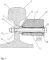
- FIG. 3 shows a cross section of a running rail to illustrate the attachment of a preferred embodiment of the fastening device.
- the running rail 3 has a rail head 11, a rail foot 13 and a rail web 9 connecting the two.
- the rail web 9 is penetrated in a suitable for the operation of the switching or sensor unit 22 position by a hole 7.
- the fastening device 1 of the switching or sensor unit 22 is screwed with a screw connection, consisting of a screw shaft with a head 21, a washer 23 and a nut 24.
- a leveling element 32 serves to approximate the first fastener to the rail web.
Landscapes
- Engineering & Computer Science (AREA)
- General Engineering & Computer Science (AREA)
- Mechanical Engineering (AREA)
- Chemical & Material Sciences (AREA)
- Combustion & Propulsion (AREA)
- Physics & Mathematics (AREA)
- Acoustics & Sound (AREA)
- Aviation & Aerospace Engineering (AREA)
- Architecture (AREA)
- Civil Engineering (AREA)
- Structural Engineering (AREA)
- Railway Tracks (AREA)
- Vibration Prevention Devices (AREA)
Claims (11)
- Dispositif pour le montage antivibratoire d'un ensemble commutateur ou capteur (22) sur un rail de roulement (3), comportant un premier élément de fixation (2) qui est susceptible d'être fixé sur le rail de roulement (3), un second élément de fixation (4) pour recevoir l'ensemble commutateur ou capteur (22) en le retenant, et un élément amortisseur (6), le premier et le second élément de fixation (2 ; 4) étant reliés l'un à l'autre au moyen de l'élément amortisseur (6) agencé entre eux,
caractérisé en ce que
le premier élément de fixation (2) est réalisé en forme de goujon ou de douille et le second élément de fixation (4) est réalisé en forme de douille, et
un épaississement (12, 14) est réalisé respectivement aux extrémités du second élément de fixation (2) et le diamètre extérieur (B) du premier épaississement (12) est supérieur au diamètre extérieur (G) du second épaississement (14). - Dispositif de fixation selon la revendication 1,
caractérisé en ce que
le second élément de fixation (4) enserre au moins une partie du premier élément de fixation (2). - Dispositif de fixation selon la revendication 1 ou 2,
caractérisé en ce que
à l'extrémité tournée vers le rail de roulement (3), le premier élément de fixation (2) présente une bride (8) qui, dans l'état intégré, est en appui contre le rail de roulement (3). - Dispositif de fixation selon l'une des revendications 1 à 3,
caractérisé en ce que
l'élément amortisseur (6) est constitué sensiblement en un polymère élastique. - Dispositif de fixation selon l'une des revendications 1 à 4,
caractérisé en ce que
l'élément amortisseur (6) est réalisé sous forme de couche d'amortissement sur la surface enveloppe du premier élément de fixation (2). - Dispositif de fixation selon l'une des revendications précédentes,
caractérisé en ce que
le premier élément de fixation (2) et le second élément de fixation (4) sont agencés l'un dans l'autre autour d'un axe de symétrie commun (5), et l'élément amortisseur (6) est agencé entre la face extérieure du premier élément de fixation (2) et la face intérieure du second élément de fixation (4). - Dispositif de fixation selon l'une des revendications précédentes,
caractérisé en ce que
le premier élément de fixation (2) est susceptible d'être fixé au rail de roulement au moyen d'une vis ou d'un boulon qui traverse axialement la douille du premier élément de fixation (2) ainsi qu'un perçage correspondant (7) dans l'âme (9) du rail de roulement. - Dispositif de fixation selon l'une des revendications précédentes,
caractérisé en ce que
le premier élément de fixation (2) et le second élément de fixation (4) sont réalisés cylindriques. - Dispositif de fixation selon l'une des revendications précédentes,
caractérisé en ce que
le second élément de fixation (4) est agencé de façon librement mobile dans le sens horizontal, vertical et latéral par rapport au premier élément de fixation (2) dans les limites de l'élasticité de l'élément amortisseur (6). - Dispositif de fixation selon l'une des revendications précédentes,
caractérisé en ce que
le dispositif est susceptible d'être relié à l'ensemble commutateur ou capteur (22) de telle sorte que l'ensemble commutateur ou capteur (22) est agencé latéralement à côté du rail de roulement (3) et au-dessous de la ligne de mouvement du boudin d'une roue de véhicule roulant sur le rail de roulement (3) et est espacé de cette ligne de mouvement. - Dispositif de fixation selon l'une des revendications précédentes,
caractérisé en ce que
au moins une rondelle d'étanchéité élastique (16, 20) est agencée entre la bride (8) et l'ensemble commutateur ou capteur (22).
Applications Claiming Priority (1)
| Application Number | Priority Date | Filing Date | Title |
|---|---|---|---|
| DE201310012084 DE102013012084B4 (de) | 2013-07-22 | 2013-07-22 | Vorrichtung zum schwingungsgedämpften Anbringen einer Schalt- oder Sensoreinheit an einer Fahrschiene |
Publications (2)
| Publication Number | Publication Date |
|---|---|
| EP2829656A1 EP2829656A1 (fr) | 2015-01-28 |
| EP2829656B1 true EP2829656B1 (fr) | 2018-09-05 |
Family
ID=51210334
Family Applications (1)
| Application Number | Title | Priority Date | Filing Date |
|---|---|---|---|
| EP14177600.5A Active EP2829656B1 (fr) | 2013-07-22 | 2014-07-18 | Dispositif destiné à l'installation guidée par amortissement d'oscillations d'une unité de capteur ou de commutation sur un rail de roulement |
Country Status (2)
| Country | Link |
|---|---|
| EP (1) | EP2829656B1 (fr) |
| DE (1) | DE102013012084B4 (fr) |
Families Citing this family (4)
| Publication number | Priority date | Publication date | Assignee | Title |
|---|---|---|---|---|
| CN114688433B (zh) * | 2022-03-22 | 2022-11-25 | 北京理工大学 | 一种传感器保护装置及采用该装置的传感器装配方法 |
| DE102024127484A1 (de) | 2024-09-23 | 2026-03-26 | Pintsch Gmbh | Anordnung und Verfahren zur Erkennung möglicher Positionierungsprobleme für an einer Fahrzeugschiene angebrachte Geräte und Gerätehalterungen |
| DE102024127483A1 (de) | 2024-09-23 | 2026-03-26 | Pintsch Gmbh | Grundhalterung für Gerätehalterungen für Fahrzeugschienen |
| DE102024127482A1 (de) | 2024-09-23 | 2026-03-26 | Pintsch Gmbh | Höhenverstellbare Gerätehalterung für Fahrzeugschienen |
Citations (3)
| Publication number | Priority date | Publication date | Assignee | Title |
|---|---|---|---|---|
| US1758712A (en) * | 1924-09-13 | 1930-05-13 | Fred C Morris | Antirattling bushing |
| US3009746A (en) * | 1959-07-20 | 1961-11-21 | Fred L Haushalter | Bearing structure |
| US20090289399A1 (en) * | 2007-01-22 | 2009-11-26 | Toyo Tire & Rubber Co., Ltd. | Vibration-isolating bush |
Family Cites Families (7)
| Publication number | Priority date | Publication date | Assignee | Title |
|---|---|---|---|---|
| CH332699A (de) * | 1954-08-18 | 1958-09-15 | Siemens Ag | Impulsgeber für Eisenbahnsicherungseinrichtungen, insbesondere für Achszähler |
| DE2504804A1 (de) * | 1975-02-05 | 1976-08-19 | Knorr Bremse Gmbh | Scheibenbremse fuer schienenfahrzeuge |
| DE3234651A1 (de) * | 1982-09-18 | 1984-05-10 | Dr. H. Tiefenbach Gmbh & Co, 4300 Essen | Schiene mit einem induktiven schienenschalter |
| DE3816791A1 (de) | 1988-05-17 | 1989-11-30 | Siemens Ag | Einrichtung zur befestigung eines gehaeuses an einer fahrschiene |
| AT394172B (de) | 1988-12-14 | 1992-02-10 | Josef Frauscher Fa Ing | Vorrichtung zum befestigen von schalt- und messgeraeten an den schienen von gleiswegen |
| DE4114316C1 (en) * | 1991-05-02 | 1992-07-09 | Duerkopp Adler Ag, 4800 Bielefeld, De | Damping installation for industrial sewing machine - has at least one rubber-metal sleeve on horizontal bolt to damp horizontal and vertical directions |
| WO2012075401A1 (fr) * | 2010-12-03 | 2012-06-07 | Metrom Rail, Llc | Système de détection et de sécurité de ligne de chemin de fer |
-
2013
- 2013-07-22 DE DE201310012084 patent/DE102013012084B4/de active Active
-
2014
- 2014-07-18 EP EP14177600.5A patent/EP2829656B1/fr active Active
Patent Citations (3)
| Publication number | Priority date | Publication date | Assignee | Title |
|---|---|---|---|---|
| US1758712A (en) * | 1924-09-13 | 1930-05-13 | Fred C Morris | Antirattling bushing |
| US3009746A (en) * | 1959-07-20 | 1961-11-21 | Fred L Haushalter | Bearing structure |
| US20090289399A1 (en) * | 2007-01-22 | 2009-11-26 | Toyo Tire & Rubber Co., Ltd. | Vibration-isolating bush |
Also Published As
| Publication number | Publication date |
|---|---|
| DE102013012084A1 (de) | 2015-01-22 |
| DE102013012084B4 (de) | 2015-04-30 |
| EP2829656A1 (fr) | 2015-01-28 |
Similar Documents
| Publication | Publication Date | Title |
|---|---|---|
| DE9409087U1 (de) | Haltevorrichtung für eine Mutter | |
| DE102015118314A1 (de) | Verfahren zum Befestigen eines Befestigungselements an einer Montageschiene sowie Befestigungselement | |
| DE102007041949B3 (de) | Befestiger | |
| EP2829656B1 (fr) | Dispositif destiné à l'installation guidée par amortissement d'oscillations d'une unité de capteur ou de commutation sur un rail de roulement | |
| DE102008057107A1 (de) | Wegmesssystem für ein Kupplungsausrücksystem | |
| WO2008125076A1 (fr) | Ressort à lame constitué d'un matériau composite fibres-matière plastique et élément d'application d'une force pour ce ressort | |
| EP3032113B1 (fr) | Procede de fixation d'un element de fixation sur un rail de montage et element de fixation | |
| EP3272566B1 (fr) | Véhicule doté d'un réservoir de véhicule et armature pour un réservoir de véhicule | |
| DE60314209T2 (de) | Verfahren und Vorrichtung zur Vermeidung von inneren Luftspalten in Gehäusen von magnetischen Sensoren | |
| DE102009026245A1 (de) | Vorrichtung zur Befestigung eines Anbauteils, z. B. einer Reling, an einer Fahrzeugkarosserie | |
| DE19639075B4 (de) | Befestigungseinrichtung für einen Sensor | |
| EP1261511A1 (fr) | Systeme d'essuie-glace et son procede de realisation, notamment pour une automobile | |
| DE202015103074U1 (de) | Befestigungsvorrichtung für eine Toiletteneinheit | |
| EP1903219A2 (fr) | Dispositif pour la fixation d'un composant sur un élément de support | |
| DE102007028164A1 (de) | Anordnung in einem Kraftfahrzeug | |
| EP3126575A1 (fr) | Corniche de pont et ensemble de fixation d'une corniche de pont | |
| DE102007033385B4 (de) | Vorrichtung zur Reduzierung der Relativbewegung von Bauteilen | |
| DE102010019926A1 (de) | Befestigungsanordnung zum lösbaren Befestigen eines Anbauteils | |
| DE102018107320B4 (de) | Kraftmesseinrichtung | |
| DE602005005089T2 (de) | Befestigungsgabelverbindung und montage eines teils an einem träger mittels der verbindung | |
| BE1030168B1 (de) | Lenksäule für ein Kraftfahrzeug und Verfahren zur Herstellung einer elektrisch verstellbaren Lenksäule | |
| DE102005024441B4 (de) | Herzstückblock | |
| DE102019112664A1 (de) | Drehzahlsensor, Fixiereinrichtung für einen Drehzahlsensor, Aufnahmevorrichtung für einen Drehzahlsensor, Sensorsystem mit einer Aufnahmevorrichtung und einem Drehzahlsensor und Verfahren zum verdrehsicheren Positionieren eines Drehzahlsensors | |
| EP1949041A1 (fr) | Capteur d'acceleration et garniture de pare-chocs | |
| DE202009002137U1 (de) | Pfostenträger |
Legal Events
| Date | Code | Title | Description |
|---|---|---|---|
| 17P | Request for examination filed |
Effective date: 20140718 |
|
| AK | Designated contracting states |
Kind code of ref document: A1 Designated state(s): AL AT BE BG CH CY CZ DE DK EE ES FI FR GB GR HR HU IE IS IT LI LT LU LV MC MK MT NL NO PL PT RO RS SE SI SK SM TR |
|
| AX | Request for extension of the european patent |
Extension state: BA ME |
|
| PUAI | Public reference made under article 153(3) epc to a published international application that has entered the european phase |
Free format text: ORIGINAL CODE: 0009012 |
|
| R17P | Request for examination filed (corrected) |
Effective date: 20150717 |
|
| RBV | Designated contracting states (corrected) |
Designated state(s): AL AT BE BG CH CY CZ DE DK EE ES FI FR GB GR HR HU IE IS IT LI LT LU LV MC MK MT NL NO PL PT RO RS SE SI SK SM TR |
|
| 17Q | First examination report despatched |
Effective date: 20160418 |
|
| STAA | Information on the status of an ep patent application or granted ep patent |
Free format text: STATUS: EXAMINATION IS IN PROGRESS |
|
| GRAP | Despatch of communication of intention to grant a patent |
Free format text: ORIGINAL CODE: EPIDOSNIGR1 |
|
| STAA | Information on the status of an ep patent application or granted ep patent |
Free format text: STATUS: GRANT OF PATENT IS INTENDED |
|
| INTG | Intention to grant announced |
Effective date: 20180307 |
|
| GRAS | Grant fee paid |
Free format text: ORIGINAL CODE: EPIDOSNIGR3 |
|
| GRAA | (expected) grant |
Free format text: ORIGINAL CODE: 0009210 |
|
| STAA | Information on the status of an ep patent application or granted ep patent |
Free format text: STATUS: THE PATENT HAS BEEN GRANTED |
|
| AK | Designated contracting states |
Kind code of ref document: B1 Designated state(s): AL AT BE BG CH CY CZ DE DK EE ES FI FR GB GR HR HU IE IS IT LI LT LU LV MC MK MT NL NO PL PT RO RS SE SI SK SM TR |
|
| REG | Reference to a national code |
Ref country code: GB Ref legal event code: FG4D Free format text: NOT ENGLISH |
|
| REG | Reference to a national code |
Ref country code: CH Ref legal event code: EP |
|
| REG | Reference to a national code |
Ref country code: AT Ref legal event code: REF Ref document number: 1037950 Country of ref document: AT Kind code of ref document: T Effective date: 20180915 |
|
| REG | Reference to a national code |
Ref country code: IE Ref legal event code: FG4D Free format text: LANGUAGE OF EP DOCUMENT: GERMAN |
|
| REG | Reference to a national code |
Ref country code: DE Ref legal event code: R096 Ref document number: 502014009361 Country of ref document: DE |
|
| REG | Reference to a national code |
Ref country code: CH Ref legal event code: NV Representative=s name: FELBER UND PARTNER AG, CH |
|
| REG | Reference to a national code |
Ref country code: NL Ref legal event code: MP Effective date: 20180905 |
|
| REG | Reference to a national code |
Ref country code: LT Ref legal event code: MG4D |
|
| PG25 | Lapsed in a contracting state [announced via postgrant information from national office to epo] |
Ref country code: RS Free format text: LAPSE BECAUSE OF FAILURE TO SUBMIT A TRANSLATION OF THE DESCRIPTION OR TO PAY THE FEE WITHIN THE PRESCRIBED TIME-LIMIT Effective date: 20180905 Ref country code: FI Free format text: LAPSE BECAUSE OF FAILURE TO SUBMIT A TRANSLATION OF THE DESCRIPTION OR TO PAY THE FEE WITHIN THE PRESCRIBED TIME-LIMIT Effective date: 20180905 Ref country code: BG Free format text: LAPSE BECAUSE OF FAILURE TO SUBMIT A TRANSLATION OF THE DESCRIPTION OR TO PAY THE FEE WITHIN THE PRESCRIBED TIME-LIMIT Effective date: 20181205 Ref country code: NO Free format text: LAPSE BECAUSE OF FAILURE TO SUBMIT A TRANSLATION OF THE DESCRIPTION OR TO PAY THE FEE WITHIN THE PRESCRIBED TIME-LIMIT Effective date: 20181205 Ref country code: SE Free format text: LAPSE BECAUSE OF FAILURE TO SUBMIT A TRANSLATION OF THE DESCRIPTION OR TO PAY THE FEE WITHIN THE PRESCRIBED TIME-LIMIT Effective date: 20180905 Ref country code: GR Free format text: LAPSE BECAUSE OF FAILURE TO SUBMIT A TRANSLATION OF THE DESCRIPTION OR TO PAY THE FEE WITHIN THE PRESCRIBED TIME-LIMIT Effective date: 20181206 Ref country code: LT Free format text: LAPSE BECAUSE OF FAILURE TO SUBMIT A TRANSLATION OF THE DESCRIPTION OR TO PAY THE FEE WITHIN THE PRESCRIBED TIME-LIMIT Effective date: 20180905 |
|
| PG25 | Lapsed in a contracting state [announced via postgrant information from national office to epo] |
Ref country code: HR Free format text: LAPSE BECAUSE OF FAILURE TO SUBMIT A TRANSLATION OF THE DESCRIPTION OR TO PAY THE FEE WITHIN THE PRESCRIBED TIME-LIMIT Effective date: 20180905 Ref country code: AL Free format text: LAPSE BECAUSE OF FAILURE TO SUBMIT A TRANSLATION OF THE DESCRIPTION OR TO PAY THE FEE WITHIN THE PRESCRIBED TIME-LIMIT Effective date: 20180905 Ref country code: LV Free format text: LAPSE BECAUSE OF FAILURE TO SUBMIT A TRANSLATION OF THE DESCRIPTION OR TO PAY THE FEE WITHIN THE PRESCRIBED TIME-LIMIT Effective date: 20180905 |
|
| PG25 | Lapsed in a contracting state [announced via postgrant information from national office to epo] |
Ref country code: IS Free format text: LAPSE BECAUSE OF FAILURE TO SUBMIT A TRANSLATION OF THE DESCRIPTION OR TO PAY THE FEE WITHIN THE PRESCRIBED TIME-LIMIT Effective date: 20190105 Ref country code: CZ Free format text: LAPSE BECAUSE OF FAILURE TO SUBMIT A TRANSLATION OF THE DESCRIPTION OR TO PAY THE FEE WITHIN THE PRESCRIBED TIME-LIMIT Effective date: 20180905 Ref country code: NL Free format text: LAPSE BECAUSE OF FAILURE TO SUBMIT A TRANSLATION OF THE DESCRIPTION OR TO PAY THE FEE WITHIN THE PRESCRIBED TIME-LIMIT Effective date: 20180905 Ref country code: PL Free format text: LAPSE BECAUSE OF FAILURE TO SUBMIT A TRANSLATION OF THE DESCRIPTION OR TO PAY THE FEE WITHIN THE PRESCRIBED TIME-LIMIT Effective date: 20180905 Ref country code: RO Free format text: LAPSE BECAUSE OF FAILURE TO SUBMIT A TRANSLATION OF THE DESCRIPTION OR TO PAY THE FEE WITHIN THE PRESCRIBED TIME-LIMIT Effective date: 20180905 Ref country code: ES Free format text: LAPSE BECAUSE OF FAILURE TO SUBMIT A TRANSLATION OF THE DESCRIPTION OR TO PAY THE FEE WITHIN THE PRESCRIBED TIME-LIMIT Effective date: 20180905 Ref country code: EE Free format text: LAPSE BECAUSE OF FAILURE TO SUBMIT A TRANSLATION OF THE DESCRIPTION OR TO PAY THE FEE WITHIN THE PRESCRIBED TIME-LIMIT Effective date: 20180905 Ref country code: IT Free format text: LAPSE BECAUSE OF FAILURE TO SUBMIT A TRANSLATION OF THE DESCRIPTION OR TO PAY THE FEE WITHIN THE PRESCRIBED TIME-LIMIT Effective date: 20180905 |
|
| PG25 | Lapsed in a contracting state [announced via postgrant information from national office to epo] |
Ref country code: SM Free format text: LAPSE BECAUSE OF FAILURE TO SUBMIT A TRANSLATION OF THE DESCRIPTION OR TO PAY THE FEE WITHIN THE PRESCRIBED TIME-LIMIT Effective date: 20180905 Ref country code: SK Free format text: LAPSE BECAUSE OF FAILURE TO SUBMIT A TRANSLATION OF THE DESCRIPTION OR TO PAY THE FEE WITHIN THE PRESCRIBED TIME-LIMIT Effective date: 20180905 Ref country code: PT Free format text: LAPSE BECAUSE OF FAILURE TO SUBMIT A TRANSLATION OF THE DESCRIPTION OR TO PAY THE FEE WITHIN THE PRESCRIBED TIME-LIMIT Effective date: 20190105 |
|
| REG | Reference to a national code |
Ref country code: DE Ref legal event code: R097 Ref document number: 502014009361 Country of ref document: DE |
|
| PLBE | No opposition filed within time limit |
Free format text: ORIGINAL CODE: 0009261 |
|
| STAA | Information on the status of an ep patent application or granted ep patent |
Free format text: STATUS: NO OPPOSITION FILED WITHIN TIME LIMIT |
|
| PG25 | Lapsed in a contracting state [announced via postgrant information from national office to epo] |
Ref country code: DK Free format text: LAPSE BECAUSE OF FAILURE TO SUBMIT A TRANSLATION OF THE DESCRIPTION OR TO PAY THE FEE WITHIN THE PRESCRIBED TIME-LIMIT Effective date: 20180905 |
|
| 26N | No opposition filed |
Effective date: 20190606 |
|
| PG25 | Lapsed in a contracting state [announced via postgrant information from national office to epo] |
Ref country code: SI Free format text: LAPSE BECAUSE OF FAILURE TO SUBMIT A TRANSLATION OF THE DESCRIPTION OR TO PAY THE FEE WITHIN THE PRESCRIBED TIME-LIMIT Effective date: 20180905 |
|
| PG25 | Lapsed in a contracting state [announced via postgrant information from national office to epo] |
Ref country code: MC Free format text: LAPSE BECAUSE OF FAILURE TO SUBMIT A TRANSLATION OF THE DESCRIPTION OR TO PAY THE FEE WITHIN THE PRESCRIBED TIME-LIMIT Effective date: 20180905 |
|
| GBPC | Gb: european patent ceased through non-payment of renewal fee |
Effective date: 20190718 |
|
| PG25 | Lapsed in a contracting state [announced via postgrant information from national office to epo] |
Ref country code: TR Free format text: LAPSE BECAUSE OF FAILURE TO SUBMIT A TRANSLATION OF THE DESCRIPTION OR TO PAY THE FEE WITHIN THE PRESCRIBED TIME-LIMIT Effective date: 20180905 |
|
| REG | Reference to a national code |
Ref country code: BE Ref legal event code: MM Effective date: 20190731 |
|
| PG25 | Lapsed in a contracting state [announced via postgrant information from national office to epo] |
Ref country code: GB Free format text: LAPSE BECAUSE OF NON-PAYMENT OF DUE FEES Effective date: 20190718 |
|
| PG25 | Lapsed in a contracting state [announced via postgrant information from national office to epo] |
Ref country code: LU Free format text: LAPSE BECAUSE OF NON-PAYMENT OF DUE FEES Effective date: 20190718 Ref country code: BE Free format text: LAPSE BECAUSE OF NON-PAYMENT OF DUE FEES Effective date: 20190731 |
|
| PG25 | Lapsed in a contracting state [announced via postgrant information from national office to epo] |
Ref country code: FR Free format text: LAPSE BECAUSE OF NON-PAYMENT OF DUE FEES Effective date: 20190731 |
|
| PG25 | Lapsed in a contracting state [announced via postgrant information from national office to epo] |
Ref country code: IE Free format text: LAPSE BECAUSE OF NON-PAYMENT OF DUE FEES Effective date: 20190718 |
|
| PG25 | Lapsed in a contracting state [announced via postgrant information from national office to epo] |
Ref country code: CY Free format text: LAPSE BECAUSE OF FAILURE TO SUBMIT A TRANSLATION OF THE DESCRIPTION OR TO PAY THE FEE WITHIN THE PRESCRIBED TIME-LIMIT Effective date: 20180905 |
|
| PG25 | Lapsed in a contracting state [announced via postgrant information from national office to epo] |
Ref country code: HU Free format text: LAPSE BECAUSE OF FAILURE TO SUBMIT A TRANSLATION OF THE DESCRIPTION OR TO PAY THE FEE WITHIN THE PRESCRIBED TIME-LIMIT; INVALID AB INITIO Effective date: 20140718 Ref country code: MT Free format text: LAPSE BECAUSE OF FAILURE TO SUBMIT A TRANSLATION OF THE DESCRIPTION OR TO PAY THE FEE WITHIN THE PRESCRIBED TIME-LIMIT Effective date: 20180905 |
|
| PG25 | Lapsed in a contracting state [announced via postgrant information from national office to epo] |
Ref country code: MK Free format text: LAPSE BECAUSE OF FAILURE TO SUBMIT A TRANSLATION OF THE DESCRIPTION OR TO PAY THE FEE WITHIN THE PRESCRIBED TIME-LIMIT Effective date: 20180905 |
|
| P01 | Opt-out of the competence of the unified patent court (upc) registered |
Effective date: 20230601 |
|
| PGFP | Annual fee paid to national office [announced via postgrant information from national office to epo] |
Ref country code: DE Payment date: 20250829 Year of fee payment: 12 |
|
| PGFP | Annual fee paid to national office [announced via postgrant information from national office to epo] |
Ref country code: AT Payment date: 20250826 Year of fee payment: 12 |
|
| PGFP | Annual fee paid to national office [announced via postgrant information from national office to epo] |
Ref country code: CH Payment date: 20250825 Year of fee payment: 12 |