EP2829656B1 - Device for the vibration-damped attachment of a switching or sensor unit to a rail - Google Patents
Device for the vibration-damped attachment of a switching or sensor unit to a rail Download PDFInfo
- Publication number
- EP2829656B1 EP2829656B1 EP14177600.5A EP14177600A EP2829656B1 EP 2829656 B1 EP2829656 B1 EP 2829656B1 EP 14177600 A EP14177600 A EP 14177600A EP 2829656 B1 EP2829656 B1 EP 2829656B1
- Authority
- EP
- European Patent Office
- Prior art keywords
- fastening element
- fastening
- rail
- switching
- sensor unit
- Prior art date
- Legal status (The legal status is an assumption and is not a legal conclusion. Google has not performed a legal analysis and makes no representation as to the accuracy of the status listed.)
- Active
Links
Images
Classifications
-
- E—FIXED CONSTRUCTIONS
- E01—CONSTRUCTION OF ROADS, RAILWAYS, OR BRIDGES
- E01B—PERMANENT WAY; PERMANENT-WAY TOOLS; MACHINES FOR MAKING RAILWAYS OF ALL KINDS
- E01B26/00—Tracks or track components not covered by any one of the preceding groups
-
- F—MECHANICAL ENGINEERING; LIGHTING; HEATING; WEAPONS; BLASTING
- F16—ENGINEERING ELEMENTS AND UNITS; GENERAL MEASURES FOR PRODUCING AND MAINTAINING EFFECTIVE FUNCTIONING OF MACHINES OR INSTALLATIONS; THERMAL INSULATION IN GENERAL
- F16F—SPRINGS; SHOCK-ABSORBERS; MEANS FOR DAMPING VIBRATION
- F16F1/00—Springs
- F16F1/36—Springs made of rubber or other material having high internal friction, e.g. thermoplastic elastomers
- F16F1/38—Springs made of rubber or other material having high internal friction, e.g. thermoplastic elastomers with a sleeve of elastic material between a rigid outer sleeve and a rigid inner sleeve or pin, i.e. bushing-type
-
- F—MECHANICAL ENGINEERING; LIGHTING; HEATING; WEAPONS; BLASTING
- F16—ENGINEERING ELEMENTS AND UNITS; GENERAL MEASURES FOR PRODUCING AND MAINTAINING EFFECTIVE FUNCTIONING OF MACHINES OR INSTALLATIONS; THERMAL INSULATION IN GENERAL
- F16F—SPRINGS; SHOCK-ABSORBERS; MEANS FOR DAMPING VIBRATION
- F16F15/00—Suppression of vibrations in systems; Means or arrangements for avoiding or reducing out-of-balance forces, e.g. due to motion
- F16F15/02—Suppression of vibrations of non-rotating, e.g. reciprocating systems; Suppression of vibrations of rotating systems by use of members not moving with the rotating systems
- F16F15/04—Suppression of vibrations of non-rotating, e.g. reciprocating systems; Suppression of vibrations of rotating systems by use of members not moving with the rotating systems using elastic means
- F16F15/08—Suppression of vibrations of non-rotating, e.g. reciprocating systems; Suppression of vibrations of rotating systems by use of members not moving with the rotating systems using elastic means with rubber springs ; with springs made of rubber and metal
-
- B—PERFORMING OPERATIONS; TRANSPORTING
- B61—RAILWAYS
- B61L—GUIDING RAILWAY TRAFFIC; ENSURING THE SAFETY OF RAILWAY TRAFFIC
- B61L1/00—Devices along the route controlled by interaction with the vehicle or train
- B61L1/02—Electric devices associated with track, e.g. rail contacts
-
- B—PERFORMING OPERATIONS; TRANSPORTING
- B61—RAILWAYS
- B61L—GUIDING RAILWAY TRAFFIC; ENSURING THE SAFETY OF RAILWAY TRAFFIC
- B61L1/00—Devices along the route controlled by interaction with the vehicle or train
- B61L1/16—Devices for counting axles; Devices for counting vehicles
-
- B—PERFORMING OPERATIONS; TRANSPORTING
- B61—RAILWAYS
- B61L—GUIDING RAILWAY TRAFFIC; ENSURING THE SAFETY OF RAILWAY TRAFFIC
- B61L3/00—Devices along the route for controlling devices on the vehicle or train, e.g. to release brake or to operate a warning signal
- B61L3/02—Devices along the route for controlling devices on the vehicle or train, e.g. to release brake or to operate a warning signal at selected places along the route, e.g. intermittent control simultaneous mechanical and electrical control
- B61L3/08—Devices along the route for controlling devices on the vehicle or train, e.g. to release brake or to operate a warning signal at selected places along the route, e.g. intermittent control simultaneous mechanical and electrical control controlling electrically
- B61L3/12—Devices along the route for controlling devices on the vehicle or train, e.g. to release brake or to operate a warning signal at selected places along the route, e.g. intermittent control simultaneous mechanical and electrical control controlling electrically using magnetic or electrostatic induction; using radio waves
- B61L3/126—Constructional details
Definitions
- the present invention relates to a device for the vibration-damped attachment of a switching or sensor unit to a running rail.
- switching or sensor unit may in particular mean a rail switch for train location, direction detection, speed measurement, axle counting or the like, which in the following will only be referred to as "unit".
- a fastening device of the type mentioned shows, for example, the document DE 3816791 A1 , It discloses a device for fastening a housing to a running rail whose housing is fastened via a bracket to the rail web of a running rail. The rail was pierced to attach a fastener and then connected by a screw mechanism to the console. The attachment of the housing to the console via two height-adjustable threaded bolt. Each threaded bolt has an internal thread for receiving a mounting screw Mistake. The threaded bolts are set via threaded inserts in the console threaded inserts with screw-clamping areas in the console. To adjust the height of the housing, the fastening screws are loosened, then the threaded bolts screwed deeper into the console and then tightened the mounting screws again.
- the fastening device DE 3816791 A1 In addition to its complexity by the multi-part design and the complex assembly, considerable disadvantages and sets the housing to be fastened to the running rail, in particular when passing a rail vehicle, considerable mechanical vibrations.
- CH332 699 A discloses a device for vibration-damped mounting a sensor unit according to the preamble of claim 1.
- the previous fastening methods suggest that particularly vulnerable components such as electronic components and the like with an elastic mass to coat. This is production-consuming and yet does not eliminate the burden of other fracture-prone components of the wheel sensor.
- additional design measures are necessary because the sheath claimed additional volume.
- the volume of construction is limited by the application, namely the attachment below the functional surface of the rail, it is necessary to use the available space as efficiently as possible.
- the functional surface is defined upwards by the horizontal running line of the periphery of the wheel flange of a rail vehicle wheel.
- a fastening device with the features of claim 1. Accordingly, it is provided that a device for vibration-damped mounting of a switching or sensor unit on a running rail has a first fastening element which can be fastened to the running rail, a second fastening element for retaining receptacle the switching or sensor unit, and a damping element, wherein the first and the second fastening element are interconnected by means of the damping element arranged between them.
- the first fastening element which serves for fastening to the running rail, can be connected to the rail element in any manner known per se by means of a clamp, a screw connection, or another conventional but detachable method.
- a clamp a screw connection
- a weld a riveting, or a bond
- these connection methods are disadvantageous in that they are not or only with great effort solvable again, which would pose a problem in a preparation of the ballast bed as the switching or sensor units must then be removed regularly.
- a parenthesis is already out of the document AT 394172 B known, which is received only on the clamping mechanism of a jaw, which can be placed on the side of the rail on the rail and clamped by a trained under the rail tie rod against at least one attacking on the other side of the rail foot chuck.
- a staple offers the advantage that it is easy and above all to install quickly and can be subsequently added with little effort
- a gland in practice for fixed equipment is common and easy to install after drilling through the rail web and also subsequently solvable. Since welding and riveting are cohesive processes, they offer the advantage of high strength, but can only be removed again with great effort. Bonding offers the advantage of fast manufacturability.
- the second fastening element engages around at least a part of the first fastening element.
- a flange is provided on the first fastening element at the end of the rail facing the end, which rests in the installed state on the web of the running rail.
- the flange is usually dimensioned in cooperation with a screw connection so that a sufficient restoring moment is achieved for the load case and a permanent connection is ensured.
- a welding or gluing of the flange with the web of the rail is conceivable.
- the damping element consists essentially of an elastic polymer.
- an elastic polymer is inexpensive and easy to manufacture.
- An elasticity optimized for the load case is chosen so that it compensates for the mechanical vibrations induced by the rail vehicle and keeps it away from the unit.
- a polymer is readily moldable in the manufacturing state and usually adhesive until polymerization, whereby the two fasteners can be assembled by the damping element before mounting to the rail to a single assembly. This in turn offers the advantage of simplified handling and assembly.
- a Shore hardness of 80 could be used.
- the damping element is formed as a damping material layer on the lateral surface of the first fastening element is.
- a corresponding layer is easy to apply and to manufacture.
- a damping material strip which is executed on its surface with an adhesive layer and could be glued on site to the first fastener before a larger diameter than the outer diameter of the first fastener executed second fastener is adhered to the first fastener.
- Another production variant could make use of the good plasticity of the polymer in the not yet polymerized state in order to form a damping layer which is free of voids and bubbles and thus achieves the most homogeneous possible damping behavior.
- the first fastening element and the second fastening element is sleeve-shaped.
- a rectangular expression would be conceivable; However, preference is given to a cylindrical shape for strength and material saving reasons.
- the invention also provides that the first fastener bolt-shaped and the second fastener is sleeve-shaped.
- the first fastening element and the second fastening element are arranged one inside the other about a common axis of symmetry, and that the damping element between the outside of the first fastening element and the inside of the second fastening element is arranged. As a result, this results in a coaxial arrangement of the two fastening elements to each other, wherein the damping element or the damping layer is also at least partially coaxially therebetween.
- a removable device is to be preferred. Accordingly, a preferred embodiment is provided in which the first fastening element by means of a screw or a bolt which (r) the sleeve of the first fastening element and a corresponding bore in the web of the running rail penetrates axially and can be fastened to the running rail.
- first fastening element and the second fastening element are cylindrical. These cylindrical components are easy to manufacture and so at least for the second fastener and the production of a corresponding sleeve, a pressing or deep-drawing process is conceivable.
- a thickening is formed at the ends of the second fastening element. This avoids tilting during assembly and achieves, for example, faster assembly without the aid of lubricants. Furthermore, the advantageous positioning of the second fastening element within the housing is thereby achieved, which is then fixed by casting with a matched in their mechanical properties to the load case, the passing of one or more rail vehicles, potting compound.
- sealing collar likewise of different diameter, is mounted on the thickenings of the second fastening element (outer diameter B and G).
- the second fastening element to the first fastening element in the context of the elasticity of the damping element is arranged horizontally, vertically and laterally freely movable.
- the device with the unit is connected such that it is arranged laterally from the running rail and below the line of movement of the wheel flange of a vehicle rail driving the vehicle and spaced from this line of movement.
- At least one elastic sealing disc is arranged between the flange and the switching or sensor unit.
- the flange is dimensioned such that it serves as an abutment for the sealing washer and additionally compensates for vibrations in cooperation with the elastic sealing washer in the direction of the axis of symmetry.
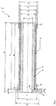
- FIG. 1 shows a cross section of an embodiment of a device 1 according to the invention.
- the fastening device 1 has a first fastening element 2, to which the rail 3 end facing a flange 8 is formed.
- the flange has a height I for a given diameter A and has a transition region 10 between flange 8 and outer diameter D of the first fastening element 2.
- an elastic, polymeric damping element 6 is arranged coaxial between the first fastening element 2 and the second fastening element 4. Also, this damping element 6 surrounds the fastening element 2 over its entire axial length. In principle, it would also be conceivable to mount the damping element 6 only in longitudinal or transverse strips on the lateral surface of the sleeve of the fastening element 2. However, a melting of the damping layer to form the damping element 6 is to give preference, resulting in a continuous functional adhesive surface of length K. The functional height of the damping element 6 results from the difference between the diameters D and E. As shown, the functional adhesive surface of the length K can also extend over the entire length J of the second fastening element 4.
- the difference between the dimensions L and M results in a defined free space lying in front of the transition region 10 to the flange 8.
- the radius of the transition region 10 is dimensioned such that, depending on the metal or metal alloy selected for the first fastening element 2, cracking in the transition region 10 is precluded.
- the materials used may be of non-metallic origin and may be formed of a non-ferromagnetic material in order to exclude interference between the switching or sensor unit 22 with the rail vehicle to be detected.
- the damping element 6 and the resulting between the outer diameters D and E thickness of the damping element 6 is selected such that for the load case in the context of elasticity of the damping element 6 horizontal, vertical and lateral clearance is ensured.
- the second fastening element has at its the flange 8 and the side of the rail 3 facing side a thickening 12 which is adapted to receive the housing of a switching or sensor unit 22.
- This first thickening 12 is defined by the outer diameter B and is larger than the outer diameter G of the flange facing away from thickening 14 of the second fastening element 4 in the illustrated embodiment.
- This realization achieved by the different design of the outer diameter B and G, a determination of the preferred mounting sequence.
- tongue and groove elements are conceivable which save additional fastening materials.
- the outer surface of the second fastening element 4 is defined by the outer diameter F and the inner surface of the second fastening element 4 by the inner diameter E.
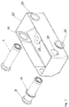
- FIG. 2 shows a perspective view of the embodiment according to FIG. 1 with a housing of a switching or sensor unit.
- the flange 8 of the first fastening element 2 and the second fastening element 4 can be seen, which are joined together to form a common assembly.
- the perspective shows elastic sealing discs 16 and 20 of different diameters, which in cooperation with the flange 8 or the first or second fastening element 2 and 4, and the housing of the switching or sensor unit 22 in coaxial and partly also in the radial direction oscillations additionally compensate.
- a housing bore 28 which, in cooperation with the thickening 12, is adapted to receive the housing of a switching or sensor unit 22.
- a cable bushing 26 serves as a receptacle for the passage of a connecting cable of the switching or sensor unit 22 in order to ensure the correct positioning of the connection cable before the subsequent fixing.
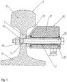
- FIG. 3 shows a cross section of a running rail to illustrate the attachment of a preferred embodiment of the fastening device.
- the running rail 3 has a rail head 11, a rail foot 13 and a rail web 9 connecting the two.
- the rail web 9 is penetrated in a suitable for the operation of the switching or sensor unit 22 position by a hole 7.
- the fastening device 1 of the switching or sensor unit 22 is screwed with a screw connection, consisting of a screw shaft with a head 21, a washer 23 and a nut 24.
- a leveling element 32 serves to approximate the first fastener to the rail web.
Landscapes
- Engineering & Computer Science (AREA)
- General Engineering & Computer Science (AREA)
- Mechanical Engineering (AREA)
- Chemical & Material Sciences (AREA)
- Combustion & Propulsion (AREA)
- Physics & Mathematics (AREA)
- Acoustics & Sound (AREA)
- Aviation & Aerospace Engineering (AREA)
- Architecture (AREA)
- Civil Engineering (AREA)
- Structural Engineering (AREA)
- Railway Tracks (AREA)
- Vibration Prevention Devices (AREA)
Description
Die vorliegende Erfindung betrifft eine Vorrichtung zum schwingungsgedämpften Anbringen einer Schalt- oder Sensoreinheit an einer Fahrschiene.The present invention relates to a device for the vibration-damped attachment of a switching or sensor unit to a running rail.
Unter dem Begriff Schalt- oder Sensoreinheit kann insbesondere ein Schienenschalter zur Zugortung, Richtungserkennung, Geschwindigkeitsmessung, Achszählung oder dergleichen gemeint sein, welcher im Folgenden nur noch als "Einheit" bezeichnet werden soll.The term switching or sensor unit may in particular mean a rail switch for train location, direction detection, speed measurement, axle counting or the like, which in the following will only be referred to as "unit".
Aus dem Stand der Technik sind bereits Befestigungsvorrichtungen an Fahrschienen, insbesondere zur Befestigung von Schalt- und Messgeräten, bekannt.Fastening devices on rails, in particular for fastening of switching and measuring devices, are already known from the prior art.
Eine Befestigungsvorrichtung der eingangs genannten Art zeigt beispielsweise die Druckschrift
Die Befestigungsvorrichtung aus
Es ist daher die Aufgabe der vorliegenden Erfindung, eine Schalt- oder Sensor-Einheit schwingungstechnisch von der Schiene zu entkoppeln und eine Befestigungsvorrichtung für einen solchen Sensor an einer Fahrschiene in vorteilhafter Weise dahingehend weiterzubilden, dass sie einfach und kostengünstig herzustellen und zu montieren ist, und dass die Zuverlässigkeit und Haltbarkeit von zu befestigenden Sendern und Messgeräten verbessert und gleichzeitig ein möglichst geringes Bauvolumen beansprucht wird.It is therefore an object of the present invention to decouple a switching or sensor unit vibrationally from the rail and an attachment device for such a sensor on a running rail in an advantageous manner to the effect that it is simple and inexpensive to manufacture and assemble, and that the reliability and durability of transmitters and measuring devices to be fastened improved and at the same time the lowest possible construction volume is claimed.
Diese Aufgabe wird erfindungsgemäß durch eine Befestigungsvorrichtung mit den Merkmalen des Anspruchs 1 gelöst. Demnach ist vorgesehen, dass eine Vorrichtung zum schwingungsgedämpften Anbringen einer Schalt- oder Sensoreinheit an einer Fahrschiene ein erstes Befestigungselement aufweist, welches an der Fahrschiene befestigbar ist, ein zweites Befestigungselement zur halternden Aufnahme der Schalt- oder Sensoreinheit, und ein Dämpfungselement, wobei das erste und das zweite Befestigungselement mittels des zwischen ihnen angeordneten Dämpfungselements miteinander verbunden sind.This object is achieved by a fastening device with the features of
Dadurch ergibt sich insbesondere der Vorteil, dass für den Lastfall, der Vorbeifahrt eines oder mehrerer Schienenfahrzeuge, eine weitestgehende mechanische Entkopplung zwischen der Fahrschiene und der Schalt- oder Sensor-Einheit erzielt wird. Die in der Einheit befindlichen Bauteile erreichen so eine längere Lebensdauer und können weniger aufwändig gegen Erschütterungen abgesichert werden. Daraus sich ergebender zusätzlicher Bauraum kann entsprechend für weitere technische Lösungen genutzt werden. Gleichzeitig wird die Messgenauigkeit der in der Schalt- oder Sensoreinheit enthaltenen Sensoren im Vergleich mit einer nicht schwingungsgedämpften Befestigungsvorrichtung idealerweise nicht verringert.This results in particular the advantage that for the load case, the passage of one or more rail vehicles, a largely mechanical decoupling between the rail and the switching or sensor unit is achieved. The components contained in the unit thus achieve a longer service life and can be less costly secured against vibrations. Resulting additional space can be used accordingly for other technical solutions. At the same time, the measuring accuracy of the sensors contained in the switching or sensor unit is ideally not reduced in comparison with a non-vibration-damping fastening device.
Das erste Befestigungselement, welches zur Befestigung an der Fahrschiene dient, kann auf beliebige und in an sich bekannter Weise mittels einer Klammer, einer Verschraubung, oder einer anderen gebräuchlichen, aber wieder lösbaren Methode mit dem Schienenelement verbunden werden. Grundsätzlich ist zwar auch eine Schweißung, eine Nietung, oder eine Klebung denkbar; diese Verbindungsmethoden sind allerdings insofern von Nachteil, dass sie nicht oder nur mit größerem Aufwand wieder lösbar sind, was sich bei einer Aufbereitung des Gleisschotterbettes als Problem darstellen würde, da die Schalt- oder Sensor-Einheiten dann regelmäßig ausgebaut werden müssen. Darüber hinaus bestünde die Gefahr, einen Sensor durch Schweißen thermisch zu zerstören.The first fastening element, which serves for fastening to the running rail, can be connected to the rail element in any manner known per se by means of a clamp, a screw connection, or another conventional but detachable method. In principle, although a weld, a riveting, or a bond is conceivable; However, these connection methods are disadvantageous in that they are not or only with great effort solvable again, which would pose a problem in a preparation of the ballast bed as the switching or sensor units must then be removed regularly. In addition, there would be a risk of thermally destroying a sensor by welding.
Eine Klammerung ist bereits aus der Druckschrift
Vorteilhafte Weiterbildungen der Erfindung sind in den Unteransprüchen angegeben.Advantageous developments of the invention are specified in the subclaims.
Um eine effektive Entkopplung des ersten und des zweiten Befestigungselements zu erreichen, ist vorgesehen, dass das zweite Befestigungselement wenigstens einen Teil des ersten Befestigungselements umgreift. Dies hat den Vorteil, dass man bei der Wahl des Fertigungsverfahrens und der Ausgestaltung des Übergangs zwischen dem Dämpfungselement und den Befestigungselementen mehr konstruktiven Freiraum erhält. So wäre eine bereits vorgefertigte Baugruppe aus den beiden Befestigungselementen und dem Dämpfungselement vorstellbar, bei der das zweite Befestigungselement geschlossen oder mehrteilig ausgeführt und das Dämpfungselement in geeigneter Weise vorgespannt ist. Grundsätzlich könnte das zweite Befestigungselement auch geschlitzt ausgeführt sein, was sich allerdings fertigungstechnisch als aufwändiger erweist.In order to achieve an effective decoupling of the first and the second fastening element, it is provided that the second fastening element engages around at least a part of the first fastening element. This has the advantage that you get more constructive freedom in the choice of manufacturing process and the design of the transition between the damping element and the fasteners. Thus, an already prefabricated assembly of the two fastening elements and the damping element would be conceivable in which the second fastening element is closed or executed in several parts and the damping element is biased in a suitable manner. In principle, the second fastening element could also be designed slotted, which, however, proves to be more expensive to produce.
Um eine gute Haltewirkung des ersten Befestigungselements an der Fahrschiene zu erreichen, ist am ersten Befestigungselement an dem der Fahrschiene zugewandten Ende ein Flansch vorgesehen, der im eingebauten Zustand an dem Steg der Fahrschiene anliegt. Der Flansch ist in der Regel im Zusammenwirken mit einer Schraubverbindung so dimensioniert, dass für den Lastfall ein ausreichendes Rückstellmoment erzielt wird und eine dauerhafte Verbindung gewährleistet ist. Allerdings ist auch eine Verschweißung oder Verklebung des Flansches mit dem Steg der Fahrschiene denkbar.In order to achieve a good holding action of the first fastening element on the running rail, a flange is provided on the first fastening element at the end of the rail facing the end, which rests in the installed state on the web of the running rail. The flange is usually dimensioned in cooperation with a screw connection so that a sufficient restoring moment is achieved for the load case and a permanent connection is ensured. However, a welding or gluing of the flange with the web of the rail is conceivable.
In bevorzugter Weise ist vorgesehen, dass das Dämpfungselement im Wesentlichen aus einem elastischen Polymer besteht. Ein derartiges elastisches Polymer ist kostengünstig und leicht herzustellen. Eine für den Lastfall optimierte Elastizität ist so gewählt, dass sie die vom Schienenfahrzeug induzierten, mechanischen Schwingungen kompensiert und von der Einheit fern hält. Ein Polymer ist im Herstellungszustand gut formbar und in der Regel bis zur Polymerisation adhäsiv, wodurch die beiden Befestigungsmittel durch das Dämpfungselement bereits vor dem Anbau an die Fahrschiene zu einer einzigen Baugruppe zusammengefügt werden können. Dies wiederum bietet den Vorteil einer vereinfachten Handhabung und Montage. Im Fall des zu verwendenden Elastomers könnte beispielsweise eine Shore-Härte von 80 Anwendung finden.Preferably, it is provided that the damping element consists essentially of an elastic polymer. Such an elastic polymer is inexpensive and easy to manufacture. An elasticity optimized for the load case is chosen so that it compensates for the mechanical vibrations induced by the rail vehicle and keeps it away from the unit. A polymer is readily moldable in the manufacturing state and usually adhesive until polymerization, whereby the two fasteners can be assembled by the damping element before mounting to the rail to a single assembly. This in turn offers the advantage of simplified handling and assembly. For example, in the case of the elastomer to be used, a Shore hardness of 80 could be used.
Des Weiteren kann vorgesehen sein, dass das Dämpfungselement als Dämpfungsmaterialschicht auf der Mantelfläche des ersten Befestigungselements ausgebildet ist. Eine entsprechende Schicht ist leicht aufzubringen und zu fertigen. Denkbar wären auch ein Dämpfungsmaterialstreifen, der auf seiner Oberfläche mit einer adhäsiven Schicht ausgeführt ist und noch vor Ort an das erste Befestigungselement aufgeklebt werden könnte, bevor ein im Durchmesser größer als der Außendurchmesser des ersten Befestigungselements ausgeführtes zweites Befestigungselement auf das erste Befestigungselement aufgeklebt wird. Eine weitere Herstellungsvariante könnte sich die gute Formbarkeit des Polymers im noch nicht polymerisierten Zustand zunutze machen, um eine Dämpfungsschicht auszubilden, die frei von Lunkern und Bläschen ist und so ein möglichst homogenes Dämpfungsverhalten erzielt. Erfindungsgemäß ist vorgesehen, dass das erste Befestigungselement und das zweite Befestigungselement hülsenförmig ausgebildet ist. Grundsätzlich wäre eine rechteckige Ausprägung denkbar; allerdings ist einer zylindrischen Ausprägung aus Festigkeits- und Materialersparnisgründen der Vorzug zu geben. Um mehr konstruktiven Spielraum bei der Ausgestaltung der Befestigung des ersten Befestigungselements an der Fahrschiene zu erhalten, ist erfindungsgemäß auch vorgesehen, dass das erste Befestigungselement bolzenförmig und das zweite Befestigungselement hülsenförmig ausgebildet ist. In besonders bevorzugter Weise ist vorgesehen, dass das erste Befestigungselement und das zweite Befestigungselement ineinander um eine gemeinsame Symmetrieachse angeordnet sind, und dass das Dämpfungselement zwischen der Außenseite des ersten Befestigungselements und der Innenseite des zweiten Befestigungselements angeordnet ist. Das führt im Ergebnis zu einer koaxialen Anordnung der beiden Befestigungselemente zueinander, wobei das Dämpfungselement bzw. die Dämpfungsschicht ebenfalls wenigstens teilweise koaxial dazwischen liegt.Furthermore, it can be provided that the damping element is formed as a damping material layer on the lateral surface of the first fastening element is. A corresponding layer is easy to apply and to manufacture. Also conceivable would be a damping material strip, which is executed on its surface with an adhesive layer and could be glued on site to the first fastener before a larger diameter than the outer diameter of the first fastener executed second fastener is adhered to the first fastener. Another production variant could make use of the good plasticity of the polymer in the not yet polymerized state in order to form a damping layer which is free of voids and bubbles and thus achieves the most homogeneous possible damping behavior. According to the invention it is provided that the first fastening element and the second fastening element is sleeve-shaped. Basically, a rectangular expression would be conceivable; However, preference is given to a cylindrical shape for strength and material saving reasons. In order to obtain more design freedom in the design of the attachment of the first fastener to the running rail, the invention also provides that the first fastener bolt-shaped and the second fastener is sleeve-shaped. In a particularly preferred manner it is provided that the first fastening element and the second fastening element are arranged one inside the other about a common axis of symmetry, and that the damping element between the outside of the first fastening element and the inside of the second fastening element is arranged. As a result, this results in a coaxial arrangement of the two fastening elements to each other, wherein the damping element or the damping layer is also at least partially coaxially therebetween.
Mit dem Ziel, die Wartungsfreundlichkeit der erfindungsgemäßen Vorrichtung weiter zu erhöhen, ist einer demontierbaren Vorrichtung der Vorzug zu geben. Entsprechend ist eine bevorzugte Ausprägung vorgesehen, bei der das erste Befestigungselement mittels einer Schraube oder eines Schraubbolzens, welche(r) die Hülse des ersten Befestigungselements sowie eine korrespondierende Bohrung im Steg der Fahrschiene axial durchdringt und an der Fahrschiene befestigbar ist.With the aim of further increasing the ease of maintenance of the device according to the invention, a removable device is to be preferred. Accordingly, a preferred embodiment is provided in which the first fastening element by means of a screw or a bolt which (r) the sleeve of the first fastening element and a corresponding bore in the web of the running rail penetrates axially and can be fastened to the running rail.
Im Weiteren ist vorzugsweise vorgesehen, dass das erste Befestigungselement und das zweite Befestigungselement zylindrisch ausgebildet sind. Diese zylindrischen Bauteile sind leicht zu fertigen und so ist mindestens für das zweite Befestigungselement und die Herstellung einer entsprechenden Hülse ein Press- oder Tiefziehverfahren denkbar.Furthermore, it is preferably provided that the first fastening element and the second fastening element are cylindrical. These cylindrical components are easy to manufacture and so at least for the second fastener and the production of a corresponding sleeve, a pressing or deep-drawing process is conceivable.
Um die Anbringung einer Einheit am zweiten Befestigungselement zu gewährleisten und beispielsweise ein Gehäuse auf das zweite Befestigungselement leicht aufstecken zu können, ist erfindungsgemäß vorgesehen, dass an den Enden des zweiten Befestigungselements eine Verdickung ausgebildet ist. Damit wird ein Verkanten bei der Montage vermieden und beispielsweise eine schnellere Montierbarkeit ohne Zuhilfenahme von Gleit- oder Schmiermitteln erreicht. Des Weiteren wird dadurch die vorteilhafte Positionierung des zweiten Befestigungselements innerhalb des Gehäuses erreicht, welches dann durch Vergießen mit einer in ihren mechanischen Eigenschaften auf den Lastfall, der Vorbeifahrt eines oder mehrerer Schienenfahrzeuge, abgestimmten Vergußmasse fixiert wird. Um eine völlige Abdichtung der Verankerung der verbundenen Befestigungselemente mit dem Gehäuse zu erreichen, ist eine Variante denkbar, in der Dichtungskragen, ebenfalls mit unterschiedlichem Durchmesser, an den Verdickungen des zweiten Befestigungselements (Außendurchmesser B und G) montiert werden.In order to ensure the attachment of a unit to the second fastening element and, for example, to easily attach a housing to the second fastening element, it is provided according to the invention that a thickening is formed at the ends of the second fastening element. This avoids tilting during assembly and achieves, for example, faster assembly without the aid of lubricants. Furthermore, the advantageous positioning of the second fastening element within the housing is thereby achieved, which is then fixed by casting with a matched in their mechanical properties to the load case, the passing of one or more rail vehicles, potting compound. In order to achieve complete sealing of the anchoring of the connected fastening elements with the housing, a variant is conceivable in which sealing collar, likewise of different diameter, is mounted on the thickenings of the second fastening element (outer diameter B and G).
In besonders bevorzugter Weise ist vorgesehen, dass das zweite Befestigungselement zum ersten Befestigungselement im Rahmen der Elastizität des Dämpfungselements horizontal, vertikal und lateral frei beweglich angeordnet ist. Als wesentliches Konstruktionsmerkmal ist bei der Dimensionierung für den bevorzugten Lastfall hierauf zu achten.In a particularly preferred manner, it is provided that the second fastening element to the first fastening element in the context of the elasticity of the damping element is arranged horizontally, vertically and laterally freely movable. As an essential design feature, attention must be paid when dimensioning for the preferred load case.
Weiter ist vorzugsweise vorgesehen, dass die Vorrichtung mit der Einheit derart verbindbar ist, dass diese seitlich von der Fahrschiene und unterhalb der Bewegungslinie des Spurkranzes eines die Fahrschiene befahrenden Fahrzeugrades angeordnet und von dieser Bewegungslinie beabstandet ist.Further, it is preferably provided that the device with the unit is connected such that it is arranged laterally from the running rail and below the line of movement of the wheel flange of a vehicle rail driving the vehicle and spaced from this line of movement.
Schließlich ist es möglich, dass zwischen dem Flansch und der Schalt- oder Sensoreinheit mindestens eine elastische Dichtungsscheibe angeordnet ist. Der Flansch ist dabei derart dimensioniert, dass er als Widerlager für die Dichtungsscheibe dient und im Zusammenwirken mit der elastischen Dichtungsscheibe in Richtung der Symmetrieachse verlaufende Schwingungen zusätzlich kompensiert. Im Folgenden wird ein bevorzugtes Ausführungsbeispiel der Erfindung anhand einer Zeichnung näher erläutert.Finally, it is possible that at least one elastic sealing disc is arranged between the flange and the switching or sensor unit. The flange is dimensioned such that it serves as an abutment for the sealing washer and additionally compensates for vibrations in cooperation with the elastic sealing washer in the direction of the axis of symmetry. In the following, a preferred embodiment of the invention will be explained in more detail with reference to a drawing.
Es zeigt:
- Fig 1.
- Einen Längsschnitt der Befestigungsvorrichtung gemäß der Erfindung;
- Fig 2.
- Eine perspektivische Darstellung des Ausführungsbeispiels gemäß
Fig. 1 mit einem Gehäuse für eine Schalt- oder Sensoreinheit; und - Fig 3.
- Einen Querschnitt durch eine Fahrschiene, durch die Befestigungsvorrichtung und das Gehäuse zur Verdeutlichung einer bevorzugten Anbringung der erfindungsgemäßen Befestigungsvorrichtung an der Fahrschiene.
- Fig. 1
- A longitudinal section of the fastening device according to the invention;
- Fig. 2
- A perspective view of the embodiment according to
Fig. 1 with a housing for a switching or sensor unit; and - Fig. 3
- A cross section through a running rail, through the fastening device and the housing to illustrate a preferred attachment of the fastening device according to the invention on the running rail.
Die Befestigungsvorrichtung 1 weist ein erstes Befestigungselement 2 auf, an derem der Fahrschiene 3 zugewandten Ende ein Flansch 8 ausgebildet ist. Der Flansch hat bei gegebenem Durchmesser A eine Höhe I und weist einen Übergansbereich 10 zwischen Flansch 8 und Außendurchmesser D des ersten Befestigunselements 2 auf.The
Koaxial um eine gemeinsame Symmetrieachse 5 und in radialer Richtung außen um das erste Befestigungselement 2 herum ist ein zweites Befestigungselement 4 angeordnet, welches ebenfalls hülsenförmig ausgebildet ist, und das Befestigungselement 2 auf seiner gesamten axialen Länge umgreift.Coaxially about a common axis of
Ebenfalls koaxial zwischen dem ersten Befestigungselement 2 und dem zweiten Befestigungselement 4 ist ein elastisches, polymeres Dämpfungselement 6 angeordnet. Auch dieses Dämpfungselement 6 umgreift das Befestigungselement 2 auf seiner gesamten axialen Länge. Grundsätzlich wäre auch denkbar, das Dämpfungselement 6 lediglich in Längs- oder Querstreifen auf die Mantelfläche der Hülse des Befestigungselements 2 anzubringen. Allerdings ist einer Aufschmelzung der Dämpfungsschicht zur Bildung des Dämpfungselements 6 der Vorzug zu geben, woraus sich eine durchgängige Funktionsklebefläche der Länge K ergibt. Die Funktionshöhe des Dämpfungselements 6 ergibt sich aus der Differenz der Durchmesser D und E. Die Funktionsklebefläche der Länge K kann sich wie gezeigt auch über die gesamte Länge J des zweiten Befestigungselements 4 erstrecken. Tut sie dies nicht, ergibt sich aus der Differenz der Bemaßungen L und M ein vor dem Übergangsbereich 10 zum Flansch 8 liegender, definierter Freiraum. Der Radius des Übergangsbereichs 10 ist derart dimensioniert, dass, in Abhängigkeit von dem für das erste Befestigungselement 2 gewählte Metall oder Metalllegierung eine Rissbildung im Übergangsbereich 10 ausgeschlossen ist. Generell ist auch denkbar, dass die verwendeten Materialien nichtmetallischen Ursprungs sein können und derart aus einem nicht ferromagnetischen Material ausgebildet sein können, um Interferenzen zwischen der Schalt- oder Sensoreinheit 22 mit dem zu erfassenden Schienenfahrzeug auszuschließen. In jedem Fall ist das Dämpfungselement 6 und die zwischen den Außendurchmessern D und E resultierende Dicke des Dämpfungselements 6 derart gewählt, dass für den Lastfall im Rahmen der Elastizität des Dämpfungselements 6 horizontale, vertikale und laterale Freigängigkeit sichergestellt ist.Also coaxial between the
Das zweite Befestigungselement weist an seinem dem Flansch 8 und dem der Fahrschiene 3 zugewandten Seite eine Verdickung 12 auf, die dazu geeignet ist das Gehäuse einer Schalt- oder Sensoreinheit 22 aufzunehmen. Diese erste Verdickung 12 ist über den Außendurchmesser B festgelegt und ist im dargestellten Ausführungsbeispiel größer als der Außendurchmesser G der dem Flansch abgewandten Verdickung 14 des zweiten Befestigungselements 4. Diese Realisierung erreicht durch die unterschiedliche Auslegung der Außendurchmesser B und G eine Festlegung der bevorzugten Montagereihenfolge. Gleichermaßen sind Nut- und Federelemente denkbar, die zusätzliche Befestigungsmaterialien einsparen. Im Wesentlichen ist die Außenfläche des zweiten Befestigungselements 4 über den Außendurchmesser F und die Innenfläche des zweiten Befestigungselements 4 über den Innendurchmesser E definiert.The second fastening element has at its the
Darauf ist der Flansch 8 des ersten Befestigungselements 2 und das zweite Befestigungselement 4 zu sehen, welche zu einer gemeinsamen Baugruppe zusammengefügt sind. Die Perspektive zeigt elastische Dichtungsscheiben 16 und 20 unterschiedlichen Durchmessers, die im Zusammenwirken mit dem Flansch 8 oder dem ersten oder zweiten Befestigungselement 2 und 4, und dem Gehäuse der Schalt- oder Sensoreinheit 22 in koaxialer und zum Teil auch in radialer Richtung verlaufende Schwingungen zusätzlich kompensieren. Eine Gehäusebohrung 28, die im Zusammenwirken mit der Verdickung 12 dazu geeignet ist, das Gehäuse einer Schalt- oder Sensoreinheit 22 aufzunehmen. Eine Kabeldurchführung 26 dient als Aufnahme für die Durchführung eines Anschlusskabels der Schalt- oder Sensoreinheit 22, um vor dem anschließenden Fixieren die korrekte Positionierung des Anschlusskabels zu gewährleisten.On it, the
Die Fahrschiene 3 weist einen Schienenkopf 11, einen Schienenfuß 13 und einen die Beiden verbindenden Schienensteg 9 auf. Der Schienensteg 9 wird in einer für den Betrieb der Schalt- oder Sensoreinheit 22 geeigneten Position von einer Bohrung 7 durchdrungen. Die Befestigungsvorrichtung 1 der Schalt- oder Sensoreinheit 22 wird mit einer Schraubverbindung, bestehend aus einem Schraubenschaft mit Kopf 21, einer Unterlegscheibe 23 und einer Mutter 24, verschraubt. Da Schienenelemente in der Herstellung gewalzt werden, dient ein Nivellierungselement 32 der Angleichung des ersten Befestigungselements an dem Schienensteg. Für die Herstellung der Verschraubung kontert ein Halteblech 30 den Schraubenschaft mit Kopf 21. Eine schützende Vergußmasse 17, bestehend aus einem elastischen, nichtleitenden Material, ummantelt nicht dargestellte elektronische Bauteile und füllt den Innenraum der Schalt- oder Sensoreinheit vollständig aus. Sie dient vor allem dem Schutz vor wechselnden Witterungseinflüssen wie Feuchtigkeit, Druck und Temperatur.The running
- 11
- Befestigungsvorrichtungfastening device
- 22
- Erstes BefestigungselementFirst fastening element
- 33
- Fahrschienerunning rail
- 44
- Zweites BefestigungselementSecond fastening element
- 55
- Symmetrieachseaxis of symmetry
- 66
- Dämpfungselementdamping element
- 77
- Bohrungdrilling
- 88th
- Flanschflange
- 99
- Stegweb
- 1010
- ÜbergangsbereichTransition area
- 1111
- Kopfhead
- 1212
- Flansch zugewandte VerdickungFlange facing thickening
- 1313
- Fußfoot
- 1414
- Flansch abgewandte VerdickungFlange facing away thickening
- 16, 2016, 20
- elastische Dichtungsscheibeelastic sealing washer
- 1717
- Vergußmassesealing compound
- 2121
- Schraubenschaft mit KopfScrew shaft with head
- 2222
- Schalt- oder SensoreinheitSwitch or sensor unit
- 2323
- Unterlegscheibewasher
- 2424
- Muttermother
- 2626
- KabeldurchführungGrommet
- 2828
- Gehäusebohrunghousing bore
- 3030
- HalteblechHalteblech
- 3232
- Nivellierungselementleveling element
- AA
- Außendurchmesserouter diameter
- BB
- Außendurchmesserouter diameter
- CC
- InnendurchmesserInner diameter
- DD
- Außendurchmesserouter diameter
- Ee
- InnendurchmesserInner diameter
- FF
- Außendurchmesserouter diameter
- GG
- Außendurchmesserouter diameter
- HH
- Länge des ersten BefestigungselementsLength of the first fastener
- II
- Tiefe des Flanschs des ersten BefestigungselementsDepth of the flange of the first fastener
- JJ
- Länge des zweiten BefestigungselementsLength of the second fastener
- KK
- Funktionslänge des DämpfungselementsFunction length of the damping element
- LL
- Abstand zwischen Anschlag des Flansches und zweitem BefestigungselementDistance between stop of the flange and second fastening element
- MM
- Abstand zwischen Funktionslänge und Anschlag des FlanschesDistance between functional length and stop of the flange
Claims (11)
- A device for the vibration-damped attachment of a switching or sensor unit (22) to a rail (3) having a first fastening element (2) which is attachable to the rail (3), a second fastening element (4) for securely receiving the switching or sensor unit (22), and a damping element (6), wherein the first and the second fastening element (2; 4) are connected by means of the damping element (6) arranged between them,
characterized in that
the first fastening element (2) is of bolt-shaped configuration and the second fastening element (4) is of sleeve-shaped configuration, and wherein a thickening (12, 14) is formed on the respective ends of the second fastening element (2) and the outer diameter (B) of the first thickening (12) is larger than the outer diameter (G) of the second thickening (14). - The fastening device according to claim 1,
characterized in that
the second fastening element (4) engages around at least a portion of the first fastening element (2). - The fastening device according to claim 1 or 2,
characterized in that
the first fastening element (2) comprises a flange (8) on the end facing the rail (3) which abuts against the rail (3) in the installed state. - The fastening device according to one of claims 1 to 3,
characterized in that
the damping element (6) substantially consists of an elastic polymer. - The fastening device according to one of claims 1 to 4,
characterized in that
the damping element (6) is designed as a damping layer on the lateral surface of the first fastening element (2). - The fastening device according to one of the preceding claims,
characterized in that
the first fastening element (2) and the second fastening element (4) are arranged one inside the other about a common axis of symmetry (5) and the damping element (6) is arranged between the outer side of the first fastening element (2) and the inner side of the second fastening element (4). - The fastening device according to one of the preceding claims,
characterized in that
the first fastening element (2) is attachable to the rail (3) by means of a screw or a bolt which axially penetrates the sleeve of the first fastening element (2) as well as a corresponding bore (7) in the bar (9) of the rail. - The fastening device according to one of the preceding claims,
characterized in that
the first fastening element (2) and the second fastening element (4) are of cylindrical configuration. - The fastening device according to one of the preceding claims,
characterized in that
the second fastening element (4) is disposed so as to be freely movable horizontally, vertically and laterally relative to the first fastening element (2) within the range of the elasticity of the damping element (6). - The fastening device according to one of the preceding claims,
characterized in that
the device with the switching or sensor unit (22) is connectable such that the switching or sensor unit (22) is arranged to the side of the rail (3) and below the line of movement of the wheel flange of a vehicle wheel traveling on the rail (3) and disposed at a distance from said line of movement. - The fastening device according to one of the preceding claims,
characterized in that
at least one elastic gasket (16, 20) is arranged between the flange (8) and the switching or sensor unit (22).
Applications Claiming Priority (1)
| Application Number | Priority Date | Filing Date | Title |
|---|---|---|---|
| DE201310012084 DE102013012084B4 (en) | 2013-07-22 | 2013-07-22 | Device for the vibration-damped attachment of a switching or sensor unit to a running rail |
Publications (2)
| Publication Number | Publication Date |
|---|---|
| EP2829656A1 EP2829656A1 (en) | 2015-01-28 |
| EP2829656B1 true EP2829656B1 (en) | 2018-09-05 |
Family
ID=51210334
Family Applications (1)
| Application Number | Title | Priority Date | Filing Date |
|---|---|---|---|
| EP14177600.5A Active EP2829656B1 (en) | 2013-07-22 | 2014-07-18 | Device for the vibration-damped attachment of a switching or sensor unit to a rail |
Country Status (2)
| Country | Link |
|---|---|
| EP (1) | EP2829656B1 (en) |
| DE (1) | DE102013012084B4 (en) |
Families Citing this family (4)
| Publication number | Priority date | Publication date | Assignee | Title |
|---|---|---|---|---|
| CN114688433B (en) * | 2022-03-22 | 2022-11-25 | 北京理工大学 | Sensor protection device and sensor assembly method adopting same |
| DE102024127482A1 (en) | 2024-09-23 | 2026-03-26 | Pintsch Gmbh | Height-adjustable device mount for vehicle rails |
| DE102024127484A1 (en) | 2024-09-23 | 2026-03-26 | Pintsch Gmbh | Arrangement and method for detecting possible positioning problems for devices and device holders attached to a vehicle rail |
| DE102024127483A1 (en) | 2024-09-23 | 2026-03-26 | Pintsch Gmbh | Base bracket for device holders for vehicle rails |
Citations (3)
| Publication number | Priority date | Publication date | Assignee | Title |
|---|---|---|---|---|
| US1758712A (en) * | 1924-09-13 | 1930-05-13 | Fred C Morris | Antirattling bushing |
| US3009746A (en) * | 1959-07-20 | 1961-11-21 | Fred L Haushalter | Bearing structure |
| US20090289399A1 (en) * | 2007-01-22 | 2009-11-26 | Toyo Tire & Rubber Co., Ltd. | Vibration-isolating bush |
Family Cites Families (7)
| Publication number | Priority date | Publication date | Assignee | Title |
|---|---|---|---|---|
| CH332699A (en) * | 1954-08-18 | 1958-09-15 | Siemens Ag | Pulse generator for railway safety devices, in particular for axle counters |
| DE2504804A1 (en) * | 1975-02-05 | 1976-08-19 | Knorr Bremse Gmbh | DISC BRAKE FOR RAIL VEHICLES |
| DE3234651A1 (en) * | 1982-09-18 | 1984-05-10 | Dr. H. Tiefenbach Gmbh & Co, 4300 Essen | Rail with an inductive rail switch |
| DE3816791A1 (en) | 1988-05-17 | 1989-11-30 | Siemens Ag | DEVICE FOR FASTENING A HOUSING ON A DRIVE RAIL |
| AT394172B (en) * | 1988-12-14 | 1992-02-10 | Josef Frauscher Fa Ing | DEVICE FOR FASTENING SWITCHING AND MEASURING DEVICES ON THE RAILS OF RAILWAYS |
| DE4114316C1 (en) * | 1991-05-02 | 1992-07-09 | Duerkopp Adler Ag, 4800 Bielefeld, De | Damping installation for industrial sewing machine - has at least one rubber-metal sleeve on horizontal bolt to damp horizontal and vertical directions |
| US8752797B2 (en) * | 2010-12-03 | 2014-06-17 | Metrom Rail, Llc | Rail line sensing and safety system |
-
2013
- 2013-07-22 DE DE201310012084 patent/DE102013012084B4/en active Active
-
2014
- 2014-07-18 EP EP14177600.5A patent/EP2829656B1/en active Active
Patent Citations (3)
| Publication number | Priority date | Publication date | Assignee | Title |
|---|---|---|---|---|
| US1758712A (en) * | 1924-09-13 | 1930-05-13 | Fred C Morris | Antirattling bushing |
| US3009746A (en) * | 1959-07-20 | 1961-11-21 | Fred L Haushalter | Bearing structure |
| US20090289399A1 (en) * | 2007-01-22 | 2009-11-26 | Toyo Tire & Rubber Co., Ltd. | Vibration-isolating bush |
Also Published As
| Publication number | Publication date |
|---|---|
| DE102013012084B4 (en) | 2015-04-30 |
| DE102013012084A1 (en) | 2015-01-22 |
| EP2829656A1 (en) | 2015-01-28 |
Similar Documents
| Publication | Publication Date | Title |
|---|---|---|
| DE9409087U1 (en) | Holding device for a mother | |
| DE102015118314A1 (en) | Method for attaching a fastener to a mounting rail and fastener | |
| DE102007041949B3 (en) | fasteners | |
| DE102013012084B4 (en) | Device for the vibration-damped attachment of a switching or sensor unit to a running rail | |
| DE102008057107A1 (en) | Position measuring system for clutch disengaging system in motor vehicle, has fastening element comprising plugging region gripped by through-hole formed in magnet and pluggable into mounting hole | |
| WO2008125076A1 (en) | Leaf spring made of a fiber-plastic composite and force transmission element therefor | |
| EP3032113B1 (en) | Method for fixing a fixing element to a fixing rail and fixing element | |
| EP3272566B1 (en) | Vehicle with a vehicle tank and reinforcement for a vehicle tank | |
| DE102009026245A1 (en) | Device for fixing an attachment, z. B. a railing on a vehicle body | |
| DE19639075B4 (en) | Fastening device for a sensor | |
| EP1261511A1 (en) | Window wiper system and method for the production thereof, especially for a motor vehicle | |
| DE102019112664A1 (en) | Speed sensor, fixing device for a speed sensor, receiving device for a speed sensor, sensor system with a receiving device and a speed sensor and method for the rotationally secure positioning of a speed sensor | |
| DE202015103074U1 (en) | Fastening device for a toilet unit | |
| EP1903219A2 (en) | Fastening device for fastening a component to a support part | |
| DE102007028164A1 (en) | Arrangement for use in motor vehicle, has self-tapping or self-grooving screw, which is formed as mass pin, which has receiver for cable shoe in end area turned away from support structure | |
| EP3126575A1 (en) | Bridge cap and fastening unit for fastening a bridge cap | |
| DE102007033385B4 (en) | Device for reducing the relative movement of components | |
| DE102010019926A1 (en) | Fastening arrangement for use in motor vehicle, has fastening element brought into position in which element is engaged to openings, where changing of distance of openings is caused through rotation of fastening element around axis | |
| DE102009030769A1 (en) | Fastening arrangement for fastening attachment part at extruded aluminum profile for e.g. door, has attachment part connectable with fastening part with profile after fixing bearing, and securing element securing position of bearing | |
| DE602005005089T2 (en) | FASTENING FORK CONNECTION AND ASSEMBLY OF A PART TO A SUPPORT THROUGH THE CONNECTION | |
| DE102005024441B4 (en) | Heart block | |
| WO2007054397A1 (en) | Acceleration sensor and bumper cover | |
| DE202009002137U1 (en) | post support | |
| EP1529968A1 (en) | Fastening device | |
| DE102012019253A1 (en) | Spacer for attaching an object to a wall provided with insulation |
Legal Events
| Date | Code | Title | Description |
|---|---|---|---|
| 17P | Request for examination filed |
Effective date: 20140718 |
|
| AK | Designated contracting states |
Kind code of ref document: A1 Designated state(s): AL AT BE BG CH CY CZ DE DK EE ES FI FR GB GR HR HU IE IS IT LI LT LU LV MC MK MT NL NO PL PT RO RS SE SI SK SM TR |
|
| AX | Request for extension of the european patent |
Extension state: BA ME |
|
| PUAI | Public reference made under article 153(3) epc to a published international application that has entered the european phase |
Free format text: ORIGINAL CODE: 0009012 |
|
| R17P | Request for examination filed (corrected) |
Effective date: 20150717 |
|
| RBV | Designated contracting states (corrected) |
Designated state(s): AL AT BE BG CH CY CZ DE DK EE ES FI FR GB GR HR HU IE IS IT LI LT LU LV MC MK MT NL NO PL PT RO RS SE SI SK SM TR |
|
| 17Q | First examination report despatched |
Effective date: 20160418 |
|
| STAA | Information on the status of an ep patent application or granted ep patent |
Free format text: STATUS: EXAMINATION IS IN PROGRESS |
|
| GRAP | Despatch of communication of intention to grant a patent |
Free format text: ORIGINAL CODE: EPIDOSNIGR1 |
|
| STAA | Information on the status of an ep patent application or granted ep patent |
Free format text: STATUS: GRANT OF PATENT IS INTENDED |
|
| INTG | Intention to grant announced |
Effective date: 20180307 |
|
| GRAS | Grant fee paid |
Free format text: ORIGINAL CODE: EPIDOSNIGR3 |
|
| GRAA | (expected) grant |
Free format text: ORIGINAL CODE: 0009210 |
|
| STAA | Information on the status of an ep patent application or granted ep patent |
Free format text: STATUS: THE PATENT HAS BEEN GRANTED |
|
| AK | Designated contracting states |
Kind code of ref document: B1 Designated state(s): AL AT BE BG CH CY CZ DE DK EE ES FI FR GB GR HR HU IE IS IT LI LT LU LV MC MK MT NL NO PL PT RO RS SE SI SK SM TR |
|
| REG | Reference to a national code |
Ref country code: GB Ref legal event code: FG4D Free format text: NOT ENGLISH |
|
| REG | Reference to a national code |
Ref country code: CH Ref legal event code: EP |
|
| REG | Reference to a national code |
Ref country code: AT Ref legal event code: REF Ref document number: 1037950 Country of ref document: AT Kind code of ref document: T Effective date: 20180915 |
|
| REG | Reference to a national code |
Ref country code: IE Ref legal event code: FG4D Free format text: LANGUAGE OF EP DOCUMENT: GERMAN |
|
| REG | Reference to a national code |
Ref country code: DE Ref legal event code: R096 Ref document number: 502014009361 Country of ref document: DE |
|
| REG | Reference to a national code |
Ref country code: CH Ref legal event code: NV Representative=s name: FELBER UND PARTNER AG, CH |
|
| REG | Reference to a national code |
Ref country code: NL Ref legal event code: MP Effective date: 20180905 |
|
| REG | Reference to a national code |
Ref country code: LT Ref legal event code: MG4D |
|
| PG25 | Lapsed in a contracting state [announced via postgrant information from national office to epo] |
Ref country code: RS Free format text: LAPSE BECAUSE OF FAILURE TO SUBMIT A TRANSLATION OF THE DESCRIPTION OR TO PAY THE FEE WITHIN THE PRESCRIBED TIME-LIMIT Effective date: 20180905 Ref country code: FI Free format text: LAPSE BECAUSE OF FAILURE TO SUBMIT A TRANSLATION OF THE DESCRIPTION OR TO PAY THE FEE WITHIN THE PRESCRIBED TIME-LIMIT Effective date: 20180905 Ref country code: BG Free format text: LAPSE BECAUSE OF FAILURE TO SUBMIT A TRANSLATION OF THE DESCRIPTION OR TO PAY THE FEE WITHIN THE PRESCRIBED TIME-LIMIT Effective date: 20181205 Ref country code: NO Free format text: LAPSE BECAUSE OF FAILURE TO SUBMIT A TRANSLATION OF THE DESCRIPTION OR TO PAY THE FEE WITHIN THE PRESCRIBED TIME-LIMIT Effective date: 20181205 Ref country code: SE Free format text: LAPSE BECAUSE OF FAILURE TO SUBMIT A TRANSLATION OF THE DESCRIPTION OR TO PAY THE FEE WITHIN THE PRESCRIBED TIME-LIMIT Effective date: 20180905 Ref country code: GR Free format text: LAPSE BECAUSE OF FAILURE TO SUBMIT A TRANSLATION OF THE DESCRIPTION OR TO PAY THE FEE WITHIN THE PRESCRIBED TIME-LIMIT Effective date: 20181206 Ref country code: LT Free format text: LAPSE BECAUSE OF FAILURE TO SUBMIT A TRANSLATION OF THE DESCRIPTION OR TO PAY THE FEE WITHIN THE PRESCRIBED TIME-LIMIT Effective date: 20180905 |
|
| PG25 | Lapsed in a contracting state [announced via postgrant information from national office to epo] |
Ref country code: HR Free format text: LAPSE BECAUSE OF FAILURE TO SUBMIT A TRANSLATION OF THE DESCRIPTION OR TO PAY THE FEE WITHIN THE PRESCRIBED TIME-LIMIT Effective date: 20180905 Ref country code: AL Free format text: LAPSE BECAUSE OF FAILURE TO SUBMIT A TRANSLATION OF THE DESCRIPTION OR TO PAY THE FEE WITHIN THE PRESCRIBED TIME-LIMIT Effective date: 20180905 Ref country code: LV Free format text: LAPSE BECAUSE OF FAILURE TO SUBMIT A TRANSLATION OF THE DESCRIPTION OR TO PAY THE FEE WITHIN THE PRESCRIBED TIME-LIMIT Effective date: 20180905 |
|
| PG25 | Lapsed in a contracting state [announced via postgrant information from national office to epo] |
Ref country code: IS Free format text: LAPSE BECAUSE OF FAILURE TO SUBMIT A TRANSLATION OF THE DESCRIPTION OR TO PAY THE FEE WITHIN THE PRESCRIBED TIME-LIMIT Effective date: 20190105 Ref country code: CZ Free format text: LAPSE BECAUSE OF FAILURE TO SUBMIT A TRANSLATION OF THE DESCRIPTION OR TO PAY THE FEE WITHIN THE PRESCRIBED TIME-LIMIT Effective date: 20180905 Ref country code: NL Free format text: LAPSE BECAUSE OF FAILURE TO SUBMIT A TRANSLATION OF THE DESCRIPTION OR TO PAY THE FEE WITHIN THE PRESCRIBED TIME-LIMIT Effective date: 20180905 Ref country code: PL Free format text: LAPSE BECAUSE OF FAILURE TO SUBMIT A TRANSLATION OF THE DESCRIPTION OR TO PAY THE FEE WITHIN THE PRESCRIBED TIME-LIMIT Effective date: 20180905 Ref country code: RO Free format text: LAPSE BECAUSE OF FAILURE TO SUBMIT A TRANSLATION OF THE DESCRIPTION OR TO PAY THE FEE WITHIN THE PRESCRIBED TIME-LIMIT Effective date: 20180905 Ref country code: ES Free format text: LAPSE BECAUSE OF FAILURE TO SUBMIT A TRANSLATION OF THE DESCRIPTION OR TO PAY THE FEE WITHIN THE PRESCRIBED TIME-LIMIT Effective date: 20180905 Ref country code: EE Free format text: LAPSE BECAUSE OF FAILURE TO SUBMIT A TRANSLATION OF THE DESCRIPTION OR TO PAY THE FEE WITHIN THE PRESCRIBED TIME-LIMIT Effective date: 20180905 Ref country code: IT Free format text: LAPSE BECAUSE OF FAILURE TO SUBMIT A TRANSLATION OF THE DESCRIPTION OR TO PAY THE FEE WITHIN THE PRESCRIBED TIME-LIMIT Effective date: 20180905 |
|
| PG25 | Lapsed in a contracting state [announced via postgrant information from national office to epo] |
Ref country code: SM Free format text: LAPSE BECAUSE OF FAILURE TO SUBMIT A TRANSLATION OF THE DESCRIPTION OR TO PAY THE FEE WITHIN THE PRESCRIBED TIME-LIMIT Effective date: 20180905 Ref country code: SK Free format text: LAPSE BECAUSE OF FAILURE TO SUBMIT A TRANSLATION OF THE DESCRIPTION OR TO PAY THE FEE WITHIN THE PRESCRIBED TIME-LIMIT Effective date: 20180905 Ref country code: PT Free format text: LAPSE BECAUSE OF FAILURE TO SUBMIT A TRANSLATION OF THE DESCRIPTION OR TO PAY THE FEE WITHIN THE PRESCRIBED TIME-LIMIT Effective date: 20190105 |
|
| REG | Reference to a national code |
Ref country code: DE Ref legal event code: R097 Ref document number: 502014009361 Country of ref document: DE |
|
| PLBE | No opposition filed within time limit |
Free format text: ORIGINAL CODE: 0009261 |
|
| STAA | Information on the status of an ep patent application or granted ep patent |
Free format text: STATUS: NO OPPOSITION FILED WITHIN TIME LIMIT |
|
| PG25 | Lapsed in a contracting state [announced via postgrant information from national office to epo] |
Ref country code: DK Free format text: LAPSE BECAUSE OF FAILURE TO SUBMIT A TRANSLATION OF THE DESCRIPTION OR TO PAY THE FEE WITHIN THE PRESCRIBED TIME-LIMIT Effective date: 20180905 |
|
| 26N | No opposition filed |
Effective date: 20190606 |
|
| PG25 | Lapsed in a contracting state [announced via postgrant information from national office to epo] |
Ref country code: SI Free format text: LAPSE BECAUSE OF FAILURE TO SUBMIT A TRANSLATION OF THE DESCRIPTION OR TO PAY THE FEE WITHIN THE PRESCRIBED TIME-LIMIT Effective date: 20180905 |
|
| PG25 | Lapsed in a contracting state [announced via postgrant information from national office to epo] |
Ref country code: MC Free format text: LAPSE BECAUSE OF FAILURE TO SUBMIT A TRANSLATION OF THE DESCRIPTION OR TO PAY THE FEE WITHIN THE PRESCRIBED TIME-LIMIT Effective date: 20180905 |
|
| GBPC | Gb: european patent ceased through non-payment of renewal fee |
Effective date: 20190718 |
|
| PG25 | Lapsed in a contracting state [announced via postgrant information from national office to epo] |
Ref country code: TR Free format text: LAPSE BECAUSE OF FAILURE TO SUBMIT A TRANSLATION OF THE DESCRIPTION OR TO PAY THE FEE WITHIN THE PRESCRIBED TIME-LIMIT Effective date: 20180905 |
|
| REG | Reference to a national code |
Ref country code: BE Ref legal event code: MM Effective date: 20190731 |
|
| PG25 | Lapsed in a contracting state [announced via postgrant information from national office to epo] |
Ref country code: GB Free format text: LAPSE BECAUSE OF NON-PAYMENT OF DUE FEES Effective date: 20190718 |
|
| PG25 | Lapsed in a contracting state [announced via postgrant information from national office to epo] |
Ref country code: LU Free format text: LAPSE BECAUSE OF NON-PAYMENT OF DUE FEES Effective date: 20190718 Ref country code: BE Free format text: LAPSE BECAUSE OF NON-PAYMENT OF DUE FEES Effective date: 20190731 |
|
| PG25 | Lapsed in a contracting state [announced via postgrant information from national office to epo] |
Ref country code: FR Free format text: LAPSE BECAUSE OF NON-PAYMENT OF DUE FEES Effective date: 20190731 |
|
| PG25 | Lapsed in a contracting state [announced via postgrant information from national office to epo] |
Ref country code: IE Free format text: LAPSE BECAUSE OF NON-PAYMENT OF DUE FEES Effective date: 20190718 |
|
| PG25 | Lapsed in a contracting state [announced via postgrant information from national office to epo] |
Ref country code: CY Free format text: LAPSE BECAUSE OF FAILURE TO SUBMIT A TRANSLATION OF THE DESCRIPTION OR TO PAY THE FEE WITHIN THE PRESCRIBED TIME-LIMIT Effective date: 20180905 |
|
| PG25 | Lapsed in a contracting state [announced via postgrant information from national office to epo] |
Ref country code: HU Free format text: LAPSE BECAUSE OF FAILURE TO SUBMIT A TRANSLATION OF THE DESCRIPTION OR TO PAY THE FEE WITHIN THE PRESCRIBED TIME-LIMIT; INVALID AB INITIO Effective date: 20140718 Ref country code: MT Free format text: LAPSE BECAUSE OF FAILURE TO SUBMIT A TRANSLATION OF THE DESCRIPTION OR TO PAY THE FEE WITHIN THE PRESCRIBED TIME-LIMIT Effective date: 20180905 |
|
| PG25 | Lapsed in a contracting state [announced via postgrant information from national office to epo] |
Ref country code: MK Free format text: LAPSE BECAUSE OF FAILURE TO SUBMIT A TRANSLATION OF THE DESCRIPTION OR TO PAY THE FEE WITHIN THE PRESCRIBED TIME-LIMIT Effective date: 20180905 |
|
| P01 | Opt-out of the competence of the unified patent court (upc) registered |
Effective date: 20230601 |
|
| PGFP | Annual fee paid to national office [announced via postgrant information from national office to epo] |
Ref country code: DE Payment date: 20250829 Year of fee payment: 12 |
|
| PGFP | Annual fee paid to national office [announced via postgrant information from national office to epo] |
Ref country code: AT Payment date: 20250826 Year of fee payment: 12 |
|
| PGFP | Annual fee paid to national office [announced via postgrant information from national office to epo] |
Ref country code: CH Payment date: 20250825 Year of fee payment: 12 |
|
| REG | Reference to a national code |
Ref country code: CH Ref legal event code: U11 Free format text: ST27 STATUS EVENT CODE: U-0-0-U10-U11 (AS PROVIDED BY THE NATIONAL OFFICE) Effective date: 20260807 |