EP2829485A1 - Bottle crate with height-adjustable framework insert - Google Patents
Bottle crate with height-adjustable framework insert Download PDFInfo
- Publication number
- EP2829485A1 EP2829485A1 EP13177716.1A EP13177716A EP2829485A1 EP 2829485 A1 EP2829485 A1 EP 2829485A1 EP 13177716 A EP13177716 A EP 13177716A EP 2829485 A1 EP2829485 A1 EP 2829485A1
- Authority
- EP
- European Patent Office
- Prior art keywords
- truss
- bottle crate
- bottle
- insert
- guide
- Prior art date
- Legal status (The legal status is an assumption and is not a legal conclusion. Google has not performed a legal analysis and makes no representation as to the accuracy of the status listed.)
- Granted
Links
Images


Classifications
-
- B—PERFORMING OPERATIONS; TRANSPORTING
- B65—CONVEYING; PACKING; STORING; HANDLING THIN OR FILAMENTARY MATERIAL
- B65D—CONTAINERS FOR STORAGE OR TRANSPORT OF ARTICLES OR MATERIALS, e.g. BAGS, BARRELS, BOTTLES, BOXES, CANS, CARTONS, CRATES, DRUMS, JARS, TANKS, HOPPERS, FORWARDING CONTAINERS; ACCESSORIES, CLOSURES, OR FITTINGS THEREFOR; PACKAGING ELEMENTS; PACKAGES
- B65D1/00—Containers having bodies formed in one piece, e.g. by casting metallic material, by moulding plastics, by blowing vitreous material, by throwing ceramic material, by moulding pulped fibrous material, by deep-drawing operations performed on sheet material
- B65D1/22—Boxes or like containers with side walls of substantial depth for enclosing contents
- B65D1/24—Boxes or like containers with side walls of substantial depth for enclosing contents with moulded compartments or partitions
- B65D1/243—Crates for bottles or like containers
-
- B—PERFORMING OPERATIONS; TRANSPORTING
- B65—CONVEYING; PACKING; STORING; HANDLING THIN OR FILAMENTARY MATERIAL
- B65D—CONTAINERS FOR STORAGE OR TRANSPORT OF ARTICLES OR MATERIALS, e.g. BAGS, BARRELS, BOTTLES, BOXES, CANS, CARTONS, CRATES, DRUMS, JARS, TANKS, HOPPERS, FORWARDING CONTAINERS; ACCESSORIES, CLOSURES, OR FITTINGS THEREFOR; PACKAGING ELEMENTS; PACKAGES
- B65D25/00—Details of other kinds or types of rigid or semi-rigid containers
- B65D25/02—Internal fittings
- B65D25/10—Devices to locate articles in containers
-
- B—PERFORMING OPERATIONS; TRANSPORTING
- B65—CONVEYING; PACKING; STORING; HANDLING THIN OR FILAMENTARY MATERIAL
- B65D—CONTAINERS FOR STORAGE OR TRANSPORT OF ARTICLES OR MATERIALS, e.g. BAGS, BARRELS, BOTTLES, BOXES, CANS, CARTONS, CRATES, DRUMS, JARS, TANKS, HOPPERS, FORWARDING CONTAINERS; ACCESSORIES, CLOSURES, OR FITTINGS THEREFOR; PACKAGING ELEMENTS; PACKAGES
- B65D2501/00—Containers having bodies formed in one piece
- B65D2501/24—Boxes or like containers with moulded compartments or partitions
- B65D2501/24006—Details relating to bottle crates
- B65D2501/24012—Materials
- B65D2501/24019—Mainly plastics
-
- B—PERFORMING OPERATIONS; TRANSPORTING
- B65—CONVEYING; PACKING; STORING; HANDLING THIN OR FILAMENTARY MATERIAL
- B65D—CONTAINERS FOR STORAGE OR TRANSPORT OF ARTICLES OR MATERIALS, e.g. BAGS, BARRELS, BOTTLES, BOXES, CANS, CARTONS, CRATES, DRUMS, JARS, TANKS, HOPPERS, FORWARDING CONTAINERS; ACCESSORIES, CLOSURES, OR FITTINGS THEREFOR; PACKAGING ELEMENTS; PACKAGES
- B65D2501/00—Containers having bodies formed in one piece
- B65D2501/24—Boxes or like containers with moulded compartments or partitions
- B65D2501/24006—Details relating to bottle crates
- B65D2501/2405—Construction
- B65D2501/24063—Construction of the walls
- B65D2501/2407—Apertured
-
- B—PERFORMING OPERATIONS; TRANSPORTING
- B65—CONVEYING; PACKING; STORING; HANDLING THIN OR FILAMENTARY MATERIAL
- B65D—CONTAINERS FOR STORAGE OR TRANSPORT OF ARTICLES OR MATERIALS, e.g. BAGS, BARRELS, BOTTLES, BOXES, CANS, CARTONS, CRATES, DRUMS, JARS, TANKS, HOPPERS, FORWARDING CONTAINERS; ACCESSORIES, CLOSURES, OR FITTINGS THEREFOR; PACKAGING ELEMENTS; PACKAGES
- B65D2501/00—Containers having bodies formed in one piece
- B65D2501/24—Boxes or like containers with moulded compartments or partitions
- B65D2501/24006—Details relating to bottle crates
- B65D2501/2405—Construction
- B65D2501/24121—Construction of the bottom
- B65D2501/24133—Grid, mesh
-
- B—PERFORMING OPERATIONS; TRANSPORTING
- B65—CONVEYING; PACKING; STORING; HANDLING THIN OR FILAMENTARY MATERIAL
- B65D—CONTAINERS FOR STORAGE OR TRANSPORT OF ARTICLES OR MATERIALS, e.g. BAGS, BARRELS, BOTTLES, BOXES, CANS, CARTONS, CRATES, DRUMS, JARS, TANKS, HOPPERS, FORWARDING CONTAINERS; ACCESSORIES, CLOSURES, OR FITTINGS THEREFOR; PACKAGING ELEMENTS; PACKAGES
- B65D2501/00—Containers having bodies formed in one piece
- B65D2501/24—Boxes or like containers with moulded compartments or partitions
- B65D2501/24006—Details relating to bottle crates
- B65D2501/2405—Construction
- B65D2501/24146—Connection between walls or of walls with bottom
- B65D2501/24152—Integral
-
- B—PERFORMING OPERATIONS; TRANSPORTING
- B65—CONVEYING; PACKING; STORING; HANDLING THIN OR FILAMENTARY MATERIAL
- B65D—CONTAINERS FOR STORAGE OR TRANSPORT OF ARTICLES OR MATERIALS, e.g. BAGS, BARRELS, BOTTLES, BOXES, CANS, CARTONS, CRATES, DRUMS, JARS, TANKS, HOPPERS, FORWARDING CONTAINERS; ACCESSORIES, CLOSURES, OR FITTINGS THEREFOR; PACKAGING ELEMENTS; PACKAGES
- B65D2501/00—Containers having bodies formed in one piece
- B65D2501/24—Boxes or like containers with moulded compartments or partitions
- B65D2501/24006—Details relating to bottle crates
- B65D2501/24197—Arrangements for locating the bottles
- B65D2501/24203—Construction of locating arrangements
- B65D2501/2421—Partitions
- B65D2501/24216—Partitions forming square or rectangular cells
-
- B—PERFORMING OPERATIONS; TRANSPORTING
- B65—CONVEYING; PACKING; STORING; HANDLING THIN OR FILAMENTARY MATERIAL
- B65D—CONTAINERS FOR STORAGE OR TRANSPORT OF ARTICLES OR MATERIALS, e.g. BAGS, BARRELS, BOTTLES, BOXES, CANS, CARTONS, CRATES, DRUMS, JARS, TANKS, HOPPERS, FORWARDING CONTAINERS; ACCESSORIES, CLOSURES, OR FITTINGS THEREFOR; PACKAGING ELEMENTS; PACKAGES
- B65D2501/00—Containers having bodies formed in one piece
- B65D2501/24—Boxes or like containers with moulded compartments or partitions
- B65D2501/24006—Details relating to bottle crates
- B65D2501/24197—Arrangements for locating the bottles
- B65D2501/24203—Construction of locating arrangements
- B65D2501/2421—Partitions
- B65D2501/24222—Partitions forming cells having a curved shape
-
- B—PERFORMING OPERATIONS; TRANSPORTING
- B65—CONVEYING; PACKING; STORING; HANDLING THIN OR FILAMENTARY MATERIAL
- B65D—CONTAINERS FOR STORAGE OR TRANSPORT OF ARTICLES OR MATERIALS, e.g. BAGS, BARRELS, BOTTLES, BOXES, CANS, CARTONS, CRATES, DRUMS, JARS, TANKS, HOPPERS, FORWARDING CONTAINERS; ACCESSORIES, CLOSURES, OR FITTINGS THEREFOR; PACKAGING ELEMENTS; PACKAGES
- B65D2501/00—Containers having bodies formed in one piece
- B65D2501/24—Boxes or like containers with moulded compartments or partitions
- B65D2501/24006—Details relating to bottle crates
- B65D2501/24197—Arrangements for locating the bottles
- B65D2501/24203—Construction of locating arrangements
- B65D2501/24286—Adjustable or removable constructions
-
- B—PERFORMING OPERATIONS; TRANSPORTING
- B65—CONVEYING; PACKING; STORING; HANDLING THIN OR FILAMENTARY MATERIAL
- B65D—CONTAINERS FOR STORAGE OR TRANSPORT OF ARTICLES OR MATERIALS, e.g. BAGS, BARRELS, BOTTLES, BOXES, CANS, CARTONS, CRATES, DRUMS, JARS, TANKS, HOPPERS, FORWARDING CONTAINERS; ACCESSORIES, CLOSURES, OR FITTINGS THEREFOR; PACKAGING ELEMENTS; PACKAGES
- B65D2501/00—Containers having bodies formed in one piece
- B65D2501/24—Boxes or like containers with moulded compartments or partitions
- B65D2501/24006—Details relating to bottle crates
- B65D2501/24197—Arrangements for locating the bottles
- B65D2501/24337—Means for accommodating bottles of different sizes
-
- B—PERFORMING OPERATIONS; TRANSPORTING
- B65—CONVEYING; PACKING; STORING; HANDLING THIN OR FILAMENTARY MATERIAL
- B65D—CONTAINERS FOR STORAGE OR TRANSPORT OF ARTICLES OR MATERIALS, e.g. BAGS, BARRELS, BOTTLES, BOXES, CANS, CARTONS, CRATES, DRUMS, JARS, TANKS, HOPPERS, FORWARDING CONTAINERS; ACCESSORIES, CLOSURES, OR FITTINGS THEREFOR; PACKAGING ELEMENTS; PACKAGES
- B65D2501/00—Containers having bodies formed in one piece
- B65D2501/24—Boxes or like containers with moulded compartments or partitions
- B65D2501/24006—Details relating to bottle crates
- B65D2501/24363—Handles
- B65D2501/24541—Hand holes
-
- B—PERFORMING OPERATIONS; TRANSPORTING
- B65—CONVEYING; PACKING; STORING; HANDLING THIN OR FILAMENTARY MATERIAL
- B65D—CONTAINERS FOR STORAGE OR TRANSPORT OF ARTICLES OR MATERIALS, e.g. BAGS, BARRELS, BOTTLES, BOXES, CANS, CARTONS, CRATES, DRUMS, JARS, TANKS, HOPPERS, FORWARDING CONTAINERS; ACCESSORIES, CLOSURES, OR FITTINGS THEREFOR; PACKAGING ELEMENTS; PACKAGES
- B65D2501/00—Containers having bodies formed in one piece
- B65D2501/24—Boxes or like containers with moulded compartments or partitions
- B65D2501/24006—Details relating to bottle crates
- B65D2501/24554—Stacking means
- B65D2501/24585—Stacking means for stacking or joining the crates together one upon the other, in the upright or upside-down position
- B65D2501/24598—Crates presenting a continuous stacking profile along the upper edge of at least two opposite side walls
Landscapes
- Engineering & Computer Science (AREA)
- Mechanical Engineering (AREA)
- Ceramic Engineering (AREA)
- Details Of Rigid Or Semi-Rigid Containers (AREA)
Abstract
Offenbart ist ein Flaschenkasten (2) mit einem entnehmbaren, insbesondere gitter- oder lochplattenförmigen, Fachwerkeinsatz (10), vorzugsweise aus Kunststoff, zur Aufnahme von Flaschen (14) oder Dosen. Erfindungsgemäß ist der Fachwerkeinsatz (10) im Flaschenkasten (2) zumindest über eine bestimmte Höhe vertikal geführt, wobei die Führungen (20, 22, 30) von Flaschenkasten (2) und Fachwerkeinsatz (10) derart zusammenwirken, dass der in einer ersten Ausrichtung eingesetzte Fachwerkeinsatz (10) über zumindest ein erstes Führungspaar (20, 30) bis zum Flaschenkastenboden (4) absenkbar ist und in einer zu der ersten Ausrichtung gedrehten oder gewendeten zweiten Ausrichtung über zumindest ein zweites Führungspaar (22, 30) nur bis zumindest einer vom Flaschenkastenboden (4) beabstandeten vorbestimmten Höhenposition (H) absenkbar ist.Disclosed is a bottle crate (2) with a removable, in particular grid or plate-shaped, lattice insert (10), preferably made of plastic, for receiving bottles (14) or cans. According to the invention, the trussed insert (10) in the bottle crate (2) is guided vertically at least over a certain height, wherein the guides (20, 22, 30) of bottle crate (2) and lattice truss (10) cooperate in such a way that the one used in a first orientation Trussed insert (10) via at least a first guide pair (20, 30) to the bottle case bottom (4) is lowered and in a rotated to the first orientation or second orientation about at least a second guide pair (22, 30) only to at least one of the bottle case bottom (4) spaced-apart predetermined height position (H) is lowered.
Description
Die vorliegende Erfindung betrifft einen Flaschenkasten mit einem Fachwerkeinsatz gemäß dem Oberbegriff des Anspruchs 1.The present invention relates to a bottle crate with a truss insert according to the preamble of claim 1.
Einfache Flaschenkasteneinsätze bzw. Fachwerkeinsätze zum Einsetzen in das Innere eines Flaschenkastens sind z. B. aus
Mittlerweile werden mit Flaschenkästen nicht nur unterschiedliche Flaschengrößen, sondern auch in Kartonagen zusammengefasste Getränkeverbünde, z. B. sogenannten Sixpacks, ausgeliefert. Die aus dem Stand der Technik bekannten Fachwerkeinsätze können hierfür nicht verwendet werden und müssen entnommen werden. Wenn anschließend die leeren Einzelflaschen zurücktransportiert werden sollen, fehlt jedoch das entnommene Fachwerk, das verhindert, dass die Flaschen beim Transport nicht hin- und herrutschen und gegeneinander schlagen.Meanwhile, with crates not only different bottle sizes, but also summarized in cardboard packaging groups, eg. B. so-called six-packs delivered. The truss inserts known from the prior art can not be used for this purpose and must be removed. However, if the empty single bottles are to be transported back afterwards, the removed truss is missing, which prevents the bottles from sliding back and forth during transport and striking against each other.
Aufgabe der vorliegenden Erfindung ist es, einen gegenüber dem Stand der Technik verbesserten und anwenderfreundlicheren Flaschenkasten mit einem Fachwerkeinsatz bereitzustellen, der sich sowohl zum Transport von einem Flaschen- oder Dosenverbund sowie anderen Gegenständen als auch zum Transport von einzelnen Flaschen bzw. Dosen gleichermaßen eignet.Object of the present invention is to provide a comparison with the prior art improved and more user-friendly bottle crate with a truss insert, which is equally suitable for transporting a bottle or can composite and other objects as well as for the transport of individual bottles or cans.
Diese Aufgabe wird durch die Merkmale des Anspruchs 1 gelöst. Vorteilhafte Weiterbildungen sind Gegenstand der Unteransprüche.This object is solved by the features of claim 1. Advantageous developments are the subject of the dependent claims.
Ein erfindungsgemäßer Flaschenkasten weist einen entnehmbaren Fachwerkeinsatz zur Aufnahme von Flaschen oder Dosen auf. Unter "entnehmbar" bzw. einer "Entnehmbarkeit" wird hier im Gegensatz zu "demontierbar" bzw. einer "Demontierbarkeit" eine Geeignetheit im Sinne einer geometrischen Ausgestaltung zum vorzugsweise werkzeuglosen Herausnehmen verstanden. Dabei ist der Fachwerkeinsatz im Flaschenkasten zumindest über eine bestimmte Höhe vertikal geführt, wobei die Führungen von Flaschenkasten und Fachwerkeinsatz derart zusammenwirken, dass der in einer ersten Ausrichtung eingesetzte Fachwerkeinsatz über zumindest ein erstes Führungspaar (bzw. über das Zusammenwirken dieses ersten Führungspaares) bis zum Flaschenkastenboden absenkbar ist und in einer zu der ersten Ausrichtung gedrehten oder gewendeten zweiten Ausrichtung über zumindest ein zweites Führungspaar (bzw. über das Zusammenwirken dieses zweiten Führungspaares) nur bis zumindest einer vom Flaschenkastenboden beabstandeten vorbestimmten Höhe oder Höhenposition absenkbar ist.An inventive bottle crate has a removable truss insert for receiving bottles or cans. By "removable" or a "removability" is understood here as opposed to "removable" or a "disassembly" a suitability in terms of a geometric configuration for preferably tool-free removal. Here, the truss used in the bottle crate is at least over a certain height guided vertically, the guides of bottle crate and truss work cooperate such that the used in a first orientation truss insert via at least a first pair of guides (or on the interaction of this first pair of guides) to the bottle case bottom can be lowered and lowered in a first orientation to the first orientation or turned second orientation on at least one second pair of guides (or on the interaction of this second pair of guides) only until at least one of the bottle crate floor spaced predetermined height or height position is lowered.
Somit kann der Fachwerkeinsatz, je nachdem wie dieser in den Flaschenkasten eingesetzt wird, entweder bis zum Boden abgesenkt werden, so dass er am Flaschenkastenboden aufliegt oder sich zumindest in dieser Nähe befindet, oder in eine Position oder Höhe, in welcher er vom Boden beabstandet ist, gebracht werden. D.h., der erfindungsgemäße Flaschenkasten weist somit einen höhenverstellbaren Fachwerkeinsatz auf, der in Abhängigkeit von dessen Ausrichtung in zwei unterschiedliche Höhenpositionen gebracht werden kann und in diesen schwerkraftbedingt verbleibt. Der Fachwerkeinsatz dient wie bei einem gewöhnlichen Flaschenkasten zur Aufnahme und zur seitlichen Abstützung bzw. Trennung der in den Flaschenkasten gestellten Flaschen oder Dosen. Da das Fachwerk höhenverstellbar ist, kann die Führungsebene des Fachwerkeinsatzes verändert werden.Thus, depending on how it is inserted into the bottle crate, the truss can be lowered either to the ground, so that it rests on the bottle case bottom or at least in this vicinity, or in a position or height in which it is spaced from the ground , to be brought. In other words, the bottle crate according to the invention thus has a height-adjustable truss insert which, depending on its orientation, can be brought into two different height positions and remain in them due to gravity. The half-timbered insert serves as an ordinary bottle crate for receiving and lateral support or separation of bottles or cans placed in the bottle crate. Since the truss is height adjustable, the management level of the truss use can be changed.
Aufgrund der Möglichkeit, den Fachwerkeinsatz bis zum Flaschenkastenboden absenken zu können, können mit dem Flaschenkasten Getränkeverbünde aus mehreren in Kartonage umhüllten Flaschen oder Dosen auf das abgesenkte Fachwerk gestellt werden und können somit in dem Flaschenkasten vollständig aufgenommen werden. Bei einem Flaschenkasten mit keinem höhenverstellbaren Fachwerk würden diese unter Umständen über den oberen Flaschenkastenrand hervorragen, weshalb diese Kästen nicht übereinander gestapelt werden könnten.Due to the possibility of being able to lower the trussing work to the bottom of the bottle crate, beverage crates made from several bottles or cans wrapped in cardboard can be placed on the lowered truss with the bottle crate can be placed and thus can be completely absorbed in the bottle crate. In a bottle crate with no height-adjustable truss would this possibly protrude above the upper edge of the bottle crate, which is why these boxes could not be stacked.
Wenn die Kartonage von den Getränkeverbünden entfernt wurde und die Flaschen oder Dosen geleert wurden, können diese auch als Einzelflaschen oder Dosen sicher mit dem erfindungsgemäßen Flaschenkasten transportiert werden, da bei dem erfindungsgemäßen Flaschenkasten der Fachwerkeinsatz entnommen, anders ausgerichtet und in eine vom Flaschenboden beabstandete Position gebracht werden kann, in welcher die Einzelflaschen bzw. Dosen durch das Fachwerk seitlich gestützt werden. Somit kann der erfindungsgemäße Flaschenkasten eine Vielzahl an einzelnen Flaschen oder Dosen aufnehmen und voneinander trennen, so dass die Flaschen bzw. Dosen beim Transport nicht gegeneinander schlagen und wohlmöglich zu Bruch gehen.If the cardboard was removed from the beverage associations and the bottles or cans were emptied, they can also be transported as individual bottles or cans safely with the bottle case according to the invention, as taken in the bottle case of the invention, the truss used, oriented differently and placed in a spaced position from the bottom of the bottle can be, in which the individual bottles or cans are laterally supported by the truss. Thus, the bottle case according to the invention can accommodate a variety of individual bottles or cans and separate from each other, so that the bottles or cans do not hit each other during transport and probably go to breakage.
Bei dem Fachwerkeinsatz kann es sich um ein gitter- oder lochplattenförmigen Einsatz handeln, der eine Vielzahl an Öffnungen, Durchbrüchen oder Flaschennestern aufweist, in welche Flaschen oder Dosen getrennt voneinander gestellt werden können. Der Fachwerkeinsatz kann in seiner Dicke bzw. Höhe so bemessen sein, dass er einerseits nicht viel Platz verbraucht, wenn er auf den Flaschenboden abgesenkt wird, andererseits ausreichende vertikale Führungsflächen oder Abschnitte aufweist, um ein Verkippen oder Verklemmen des Fachwerkeinsatzes beim Anheben oder Absenken des Flaschenkastens zu vermeiden.The truss insert may be a grid or plate-shaped insert having a plurality of openings, apertures or bottle nests into which bottles or cans may be placed separately. The truss can be sized in thickness or height so that on the one hand not much space consumed when it is lowered to the bottom of the bottle, on the other hand sufficient vertical guide surfaces or sections to tilt or jamming of the truss insert when lifting or lowering the bottle crate to avoid.
Der Fachwerkeinsatz kann durch Drehen oder Wenden unterschiedlich ausgerichtet werden und je nach Ausrichtung verschieden tief im Flaschenkasten abgesenkt werden. Hierzu muss der Fachwerkeinsatz entweder um 180° um eine vertikale Achse (Höhenachse) oder eine horizontale Achse (Querachse) rotiert werden. Dieses Prinzip, zumindest was die Drehung um die vertikale Achse betrifft, ist in ähnlicher Form von Drehstapelbehältern bekannt, wobei es hier nicht darauf ankommt, den Behälter in unterschiedlichen Höhen innerhalb des anderen Behälters nesten zu können.The half-timbered insert can be aligned differently by turning or turning and, depending on the orientation, lowered to different depths in the bottle crate. For this, the half-timbered insert must be rotated either by 180 ° about a vertical axis (height axis) or a horizontal axis (transverse axis). This principle, at least as far as the rotation about the vertical axis is concerned, is known in a similar form from rotary stacking containers, whereby it does not matter here to be able to nest the container at different heights within the other container.
Erfindungsgemäß wirken somit ein Innenprofil des Flaschenkastens mit einem Außenprofil des Fachwerkeinsatzes derart zusammen, dass der Fachwerkeinsatz in Abhängigkeit von dessen Ausrichtung entweder bis zum Flaschenkastenboden oder nur bis zu einer vorbestimmten Höhenposition absenkbar ist.According to the invention thus act an inner profile of the bottle crate with an outer profile of the truss insert such that the truss insert is lowered depending on its orientation either to the bottle case bottom or only up to a predetermined height position.
Im Gegensatz zu einem fest im Flaschenkasten integrierten Fachwerk ermöglicht der erfindungsgemäße Flaschenkasten auch noch den Austausch des Fachwerkeinsatzes gegen einen anderen Fachwerkeinsatz mit geeigneten und auf den Flaschenkasten abgestimmten Führungselementen, um so den Flaschenkasten für andere Flaschengrößen und -zahlen einsetzen zu können. Somit ermöglicht der erfindungsgemäße Flaschenkasten zum einen den Austausch des Fachwerkeinsatzes in Abhängigkeit der zu transportierenden Flaschen- oder Dosengrößen und darüber hinaus auch noch die Möglichkeit, die jeweiligen Flaschen- bzw. Dosengrößen im Getränkeverbund und als Einzelflaschen sicher zu transportieren.In contrast to a fixed integrated in the bottle crate truss bottle invention also allows the replacement of the truss insert against another truss use with suitable and matched to the bottle crate guide elements so as to use the bottle crate for other bottle sizes and numbers. Thus, the bottle crate according to the invention allows for a replacement of the truss use depending on the transported bottle or can sizes and beyond also the ability to safely transport the respective bottle or can sizes in the beverage network and as single bottles.
Die Austauschbarkeit des Fachwerkeinsatzes hat ferner den Vorteil, dass bei Beschädigung des Fachwerks nicht der gesamte Flaschenkasten, sondern lediglich der Fachwerkeinsatz ausgetauscht werden kann, wodurch Kosten eingespart werden können. Ferner sind der Flaschenkasten und der Fachwerkeinsatz als separate Teile leichter zu fertigen als ein integriertes Bauteil.The interchangeability of the truss use also has the advantage that in case of damage to the truss not the entire bottle crate, but only the truss can be replaced, which costs can be saved. Furthermore, the bottle crate and truss as a separate parts are easier to manufacture than an integrated component.
Gemäß einem Aspekt der Erfindung sind das erste Führungspaar, welches das Absenken bis zum Flaschenkastenboden ermöglicht, und das zweite Führungspaar, welches das Absenken nur bis zu einer vorbestimmten Höhe ermöglicht, asymmetrisch ausgebildet. Das Innenprofil des Flaschenkastens und/oder das Außenprofil des Fachwerkeinsatzes können somit asymmetrisch ausgebildet sein. Durch die Asymmetrie der Führungspaarungen wirken je nach Ausrichtung des Fachwerkeinsatzes unterschiedliche Führungspaare zusammen. Somit ist es nicht notwendig, am Flaschenkasten oder am Fachwerkeinsatz irgendwelche Veränderungen vorzunehmen, um die Höhenverstellung des Fachwerkeinsatzes zu ermöglichen. Diese Höhenverstellung basiert allein auf der Drehung oder Wendung desselben Fachwerkeinsatzes.According to one aspect of the invention, the first guide pair, which allows the lowering to the bottle case bottom, and the second guide pair, which allows the lowering only up to a predetermined height, are formed asymmetrically. The inner profile of the bottle crate and / or the outer profile of the truss insert can thus be designed asymmetrically. Due to the asymmetry of the guide pairings, different pairs of guides act together, depending on the orientation of the truss insert. Thus, it is not necessary to make any changes to the bottle crate or truss used to allow the height adjustment of the truss insert. This height adjustment is based solely on the rotation or turn of the same truss use.
Gemäß einem Aspekt der Erfindung kann das erste Führungspaar durch ein erstes fachwerkseitiges Führungselement und ein bis zum Flaschenkastenboden reichendes erstes kastenseitiges Führungselement gebildet werden. Ferner kann das zweite Führungspaar durch das erste oder ein zweites fachwerkseitiges Führungselement und ein nur bis zur vorbestimmten Höhenposition reichendes zweites kastenseitiges Führungselement gebildet werden. Somit ermöglichen die fachwerk- und kastenseitigen Führungselemente nicht nur eine vertikale Führung des Fachwerkeinsatzes beim Anheben oder Absenken, sondern begrenzen zugleich den Freiheitsgrad des Fachwerkeinsatzes im Flaschenkasten. So kann die Höhenbegrenzung allein durch die Ausgestaltung der kastenseitigen Führungselemente realisiert werden.According to one aspect of the invention, the first guide pair may be formed by a first truss-side guide element and a first box-side guide element extending to the bottle case bottom. Furthermore, the second guide pair can be formed by the first or a second framework-side guide element and a second box-side guide element reaching only up to the predetermined height position. Thus, the truss and box side guide elements not only allow vertical guidance of the truss insert when raising or lowering, but also limit the degree of freedom of the truss insert in the bottle crate. Thus, the height limit can be realized solely by the design of the box-side guide elements.
Gemäß einem Aspekt der Erfindung weist das erste fachwerkseitige Führungselement einen an einer Umfangs- bzw. Außenseite des Fachwerkeinsatzes oder an einer Innenseite bzw. Innenfläche einer Pinolenaufnahme des Fachwerkeinsatzes ausgebildeten Führungszapfen oder Führungsvorsprung auf. Die kastenseitigen Führungselemente können entsprechend in Form und Position komplementär am Flaschenkasten ausgebildet sein. So kann das erste kastenseitige Führungselement ein an einer Seiteninnenwand oder einer Pinole des Flaschenkastens ausgebildete und bis zum Flaschenkastenboden reichende erste kastenseitige Führungsnut aufweisen. Das zweite kastenseitige Führungselement kann eine an einer Seiteninnenwand oder einer Pinole des Flaschenkastens ausgebildete und nur bis zur vorbestimmten Höhenposition reichende zweite Führungsnut aufweisen. Dabei wirkt in der ersten Ausrichtung des Fachwerkeinsatzes der fachwerkseitige Führungszapfen oder -vorsprung mit der kastenseitigen ersten Führungsnut zusammen bzw. greift in diese ein und in der zweiten Ausrichtung des Fachwerkeinsatzes wirkt der fachwerkseitige Führungszapfen oder -vorsprung mit der kastenseitigen zweiten Führungsnut zusammen oder greift in diese ein. Alternativ können Führungszapfen oder -vorsprünge kastenseitig ausgebildet sein und die entsprechenden Führungsnuten fachwerkseitig ausgebildet sein, sofern sichergestellt ist, dass der Fachwerkeinsatz in Abhängigkeit von dessen Ausrichtung in unterschiedliche Höhenpositionen gebracht werden kann.According to one aspect of the invention, the first truss-side guide element has a guide pin or guide projection formed on a peripheral or outer side of the truss insert or on an inner side or inner surface of a quill receptacle of the truss insert. The box-side guide elements can be designed correspondingly in shape and position complementary to the bottle crate. Thus, the first box-side guide element may have a first box-side guide groove formed on a side inner wall or quill of the bottle crate and extending to the bottle case bottom. The second box-side guide element may have a formed on a side inner wall or quill of the bottle crate and only reaching to the predetermined height position second guide groove. In the first orientation of the truss use, the truss-side guide pin or projection cooperates with or engages the box-side first guide groove and, in the second alignment of the trussed insert, the truss-side guide pin or projection interacts with or engages with the box-side second guide groove one. Alternatively, guide pins or projections may be formed on the box side and the corresponding guide grooves formed lattice-side, if it is ensured that the truss can be placed in different height positions depending on its orientation.
Solche Führungszapfen oder -vorsprünge bzw. Führungsnuten sind fertigungstechnisch leicht herzustellen, so dass mit geringem Aufwand ein vielfältig einsetzbarer Flaschenkasten bereitgestellt werden kann.Such guide pins or protrusions or guide grooves are easy to produce in terms of production, so that a versatile bottle crate can be provided with little effort.
Gemäß einem Aspekt der Erfindung reicht die erste und/oder zweite Führungsnut nicht bis zum oberen Flaschenkastenrand. Anders gesagt laufen die Führungsnuten nach oben hin nicht aus, sondern sind geschlossen. Dadurch kann sichergestellt werden, dass der Fachwerkeinsatz nicht aus den Führungen bzw. dem Flaschenkasten rutscht, wenn dieser z. B. zu Reinigungszwecken auf den Kopf gestellt wird. Zum Entnehmen des Fachwerkeinsatzes muss dieser lediglich etwas gekippt werden, so dass die entsprechenden Führungselemente freigegeben werden.According to one aspect of the invention, the first and / or second guide groove does not extend to the upper edge of the bottle crate. In other words, the guide grooves do not run upwards but are closed. This can ensure that the truss does not slip out of the guides or the bottle crate, if this z. B. is made for cleaning purposes upside down. To remove the truss insert this must only be tilted slightly, so that the corresponding guide elements are released.
Gemäß einem Aspekt der Erfindung weist der Fachwerkeinsatz auf einer ersten Seite eine flache Auflagefläche und auf einer gegenüberliegenden Seite zwischen den Aufnahmeöffnungen bzw. Flaschennestern ausgebildete Einführschrägen auf. So kann in der ersten Ausrichtung des Fachwerkeinsatzes die flache Auflagefläche nach oben weisen bzw. die Einführschrägen nach unten weisen und in der zweiten Ausrichtung die Einführschrägen nach oben weisen und die flache Auflagefläche nach unten bzw. zum Flaschenboden hin weisen. Wenn mit dem Flaschenkasten in Kartonagen verpackte Getränkeverbünde transportiert werden sollen, muss das Fachwerk eine entsprechende flache oder ebene Auflagefläche bieten. Um andererseits das Einstellen von Einzelflaschen in das Fachwerk zu erleichtern, ist es hilfreich, wenn der Fachwerkeinsatz entsprechende Einführschrägen aufweist. Durch die Abstimmung der Führungspaare mit der Oberflächengestaltung des Fachwerkeinsatzes kann erreicht werden, dass in der bis zum Boden abgesenkten Position des Fachwerkeinsatzes die flache Auflagefläche für die Getränkeverbünde nach oben weist und in der angehobenen Position die Einführschrägen zum Einstellen der Einzelflaschen nach oben weisen.According to one aspect of the invention, the truss used on a first side of a flat support surface and on an opposite side formed between the receiving openings or bottle nests insertion bevels. Thus, in the first orientation of the truss insert the flat support surface facing up or have the insertion slopes down and in the second orientation, the insertion slopes facing up and the flat bearing surface down or to the bottom of the bottle have. If beverage containers packaged in cartons are to be transported with the bottle crate, the truss must offer a corresponding flat or level bearing surface. On the other hand, to facilitate the setting of individual bottles in the truss, it is helpful if the truss has corresponding insertion bevels. By coordinating the pairs of guides with the surface design of the truss use can be achieved that in the lowered position to the ground of the truss insert, the flat support surface for the beverage associations facing up and in the raised position, the insertion bevels for adjusting the bottles have upwards.
Gemäß einem Aspekt der Erfindung kann die Oberfläche das Flaschenkastenbodens im Wesentlichen komplementär zu der zweiten Seite des Fachwerkeinsatzes bzw. zur Seite, welche die Einführschrägen aufweist, ausgebildet sein. Diese können durch Erhabenheiten, etwa hervorstehende Stege oder Rippen ausgebildet sein. Die Stege können dabei aufeinander zu laufen und die Erhabenheit an einer einzigen oder mehren Stellen erzwingen. Beispielsweise können sie pyramidenähnlich ausgebildet und ausgerichtet sein. Sie definieren dabei zumindest theoretische Schrägen und/oder Flächen zur Rutschrichtungsvorgabe / Rutschführung der Gebinde, wie Flaschen. Dadurch wird erreicht, dass der Fachwerkeinsatz flächig am Flaschenkastenboden und nicht nur auf den Einführschrägen aufliegt. Ferner kann durch der Fachwerkeinsatz auch weiter im Flaschenkasten abgesenkt werden.According to one aspect of the invention, the surface may be the bottle crate bottom substantially complementary to the second side of the truss bit or to the side having the insertion bevels formed. These can be due to grandeur, such as protruding ridges or ribs be educated. The webs can run towards each other and enforce the grandeur at a single or multiple sites. For example, they may be pyramid-shaped and aligned. They define at least theoretical bevels and / or surfaces for slip direction setting / slide guidance of the containers, such as bottles. This ensures that the truss used rests flat on the bottle case bottom and not only on the insertion bevels. Furthermore, it can also be lowered by the truss in the bottle crate.
Gemäß einem Aspekt der Erfindung ist der Fachwerkeinsatz in der vorbestimmten Höhenposition und/oder der auf den Flaschenkastenboden abgesenkten Position feststellbar. Auch wenn über die Führungspaare der Fachwerkeinsatz in der vorbestimmten Höhe oder am Flaschenkastenboden allein durch die Schwerkraft verbleibt, kann es in manchen Situationen vorteilhaft sein, wenn der Fachwerkeinsatz in einer oder beiden Positionen arretierbar ist. Dies ist z. B. der Fall, wenn der Flaschenkasten zum Reinigen auf den Kopf gestellt werden muss. Darüber hinaus kann auch sichergestellt werden, dass der Fachwerkeinsatz beim Transport in seiner gewünschten Position bleibt, z. B. wenn der Flaschenkasten beim Tragen gekippt wird. Die lösbare Arretierung des Fachwerkeinsatzes in einer bestimmten Position kann mittels Verriegelungs- oder Verrastungsmechanismen erzielt werden.According to one aspect of the invention, the truss is detectable in the predetermined height position and / or lowered to the bottle case bottom position. Even if gravity remains on the guide pairs of the lattice work in the predetermined height or the bottle crate floor alone, it may be advantageous in some situations when the truss is locked in one or both positions. This is z. As is the case when the bottle crate must be turned upside down for cleaning. In addition, it can also be ensured that the truss used remains in its desired position during transport, z. B. when the bottle case is tilted while wearing. The releasable locking of the truss insert in a certain position can be achieved by means of locking or Verrastungsmechanismen.
Gemäß einem Aspekt der Erfindung weist das Fachwerk zumindest ein Verriegelungs- oder Verrastungselement auf, das zumindest mit einer entsprechenden im Flaschenkasten ausgebildeten Verriegelungs- oder Rastgeometrie formschlüssig zusammenwirken kann, wenn der Fachwerkeinsatz in die vorbestimmte Höhenposition oder die abgesenkte Position gebracht wird.According to one aspect of the invention, the truss has at least one locking or latching element, which can cooperate form-fitting at least with a corresponding formed in the bottle crate locking or locking geometry when the truss is placed in the predetermined height position or the lowered position.
Gemäß einem Aspekt der Erfindung kann die Verriegelung oder Verrastung selbsttätig erfolgen, so dass man auf irgendwelche Handgriffe zum Verriegeln des Fachwerkeinsatzes verzichten kann. Hierfür kann gemäß einem Aspekt der Erfindung ein fachwerkseitiges und/oder flaschenkastenseitiges Verriegelungselement federelastisch vorgespannt sein. Die Vorspannung kann in Querrichtung des Flaschenkastens erfolgen. Über die federelastische Vorspannung kann die Verriegelungskraft bzw. die Entriegelungskraft eingestellt werden, so dass der Fachwerkeinsatz auch wieder entriegelt werden kann, ohne spezielle Handgriffe.According to one aspect of the invention, the locking or latching can be done automatically, so that you can do without any handles for locking the truss insert. For this purpose, according to one aspect of the invention, a truss-side and / or bottle box-side locking element can be resiliently biased. The bias can be done in the transverse direction of the bottle crate. About the elastic preload, the Locking force and the unlocking force can be adjusted so that the truss can also be unlocked again, without special operations.
Um ein versehentliches Lösen aufgrund von Stößen auf den Fachwerkeinsatz zu verhindern, kann die Verriegelung der Gestalt sein, dass die Verriegelung selbsttätig erfolgt, wenn der Fachwerkeinsatz in die bestimmte Position gebracht wird, jedoch nur durch manuelles Betätigen des einen oder der mehreren Verriegelungselemente entriegelt werden kann.To prevent inadvertent disengagement due to impacts on the truss insert, the latch may be of the form that locking occurs automatically when the truss is moved to the specified position, but can only be unlocked by manual actuation of the one or more latch members ,
Gemäß einem Aspekt der Erfindung kann das zumindest eine fachwerkseitige Verriegelungselement als eine vorspringende Federlasche ausgebildet sein, die in eine entsprechende Ausnehmung, die am Flaschenkasten vorgesehen ist, eingreift. Diese Ausnehmung kann an einer vom Flaschenkastenboden vorspringenden Führungssäule bzw. Pinole ausgebildet sein und/oder an einem oder mehreren Seitenwandabschnitten des Flaschenkastens ausgebildet sein.According to one aspect of the invention, the at least one lattice-side locking element may be formed as a projecting spring tab, which engages in a corresponding recess which is provided on the bottle crate. This recess may be formed on a projecting from the bottle case bottom guide column or quill and / or be formed on one or more side wall portions of the bottle crate.
Anstelle von Verriegelungselementen können auch entsprechende Verrastungselemente und -geometrien an den entsprechenden Bauteilen vorgesehen sein.Instead of locking elements and corresponding latching elements and geometries can be provided on the corresponding components.
Gemäß einem Aspekt der Erfindung wird das zumindest eine Verriegelungselement bzw. das zumindest eine Verrastungselement selbsttätig entriegelt oder freigegeben, wenn eine vorbestimmte Kraft auf den Fachwerkeinsatz in Höhenrichtung aufgebracht wird. Dadurch kann der Anwender den Fachwerkeinsatz durch ledigliches Hochziehen oder Niederdrücken in unterschiedliche Positionen bringen. Da der Fachwerkeinsatz im normalen Einsatz viel öfter abgesenkt und angehoben wird als ganz aus dem Flaschenkasten entnommen wird, kann das Zusammenwirken der Verriegelungs- bzw. Verrastungselemente in der vorbestimmten Höhenposition derart abgestimmt werden, dass die Kraft zum Freigeben des Fachwerkeinsatzes in Absenkungsrichtung kleiner als die notwendige Kraft zum Freigeben des Fachwerkeinsatzes in Anhebungsrichtung bzw. Herausnahmerichtung ist. Dadurch kann sichergestellt werden, dass beim Hochziehen des Fachwerkeinsatzes dieser nicht versehentlich ganz aus dem Flaschenkasten herausgenommen wird. Alternativ kann die Verriegelung der Gestalt sein, dass zum Herausnehmen des Fachwerkeinsatzes die Verriegelungselemente manuell betätigt werden müssen, während zum Absenken des Fachwerkeinsatzes lediglich eine vorbestimmte Entriegelungskraft auf den Fachwerkeinsatz aufgebracht werden muss und die Verriegelungselemente selbsttätig den Fachwerkeinsatz freigeben.According to one aspect of the invention, the at least one locking element or the at least one locking element is automatically unlocked or released when a predetermined force is applied to the truss in the vertical direction. This allows the user to bring the half-timbered insert by simply pulling up or down in different positions. Since the half-timbered insert is lowered and raised much more often than is completely removed from the bottle crate, the interaction of the locking or Verrastungselemente in the predetermined height position can be adjusted so that the force to release the truss in the lowering direction smaller than the necessary Force to release the truss use in lifting direction or take-out direction is. This can ensure that when pulling up the truss insert this is not accidentally removed completely from the bottle crate. Alternatively, the lock may be of the shape that for removing the truss insert, the locking elements must be manually operated, while lowering the truss insert only a predetermined unlocking force must be applied to the truss and the locking elements automatically release the truss use.
Ein zusätzlicher oder eigenständiger Aspekt der Erfindung betrifft einen Satz von erfindungsgemäßen Fachwerkeinsätzen, wobei die Fachwerkeinsätze identische Verriegelungs- oder Verrastungselemente aufweisen und sich in Anzahl und Größe der Öffnungen oder Ausnehmungen zur Aufnahme von Flaschen und Dosen unterscheiden. Durch die Verwendung standardgemäßer Verriegelungs- und Führungsabschnitte können diese mit dem gleichen Flaschenkasten verwendet werden, um so den Flaschenkasten an unterschiedliche Flaschengröße anzupassen.An additional or independent aspect of the invention relates to a set of truss inserts according to the invention, wherein the truss inserts have identical locking or latching elements and differ in number and size of the openings or recesses for receiving bottles and cans. By using standard locking and guiding sections, these can be used with the same bottle crate to adapt the bottle crate to different bottle sizes.
Gemäß einem Aspekt der Erfindung können die Einsätze in Abhängigkeit von Anzahl und/oder Größe der Flaschenaufnahme unterschiedlich gestaltet sein, wodurch es zu weniger Verwechselungen beim Austauschen der Fachwerkeinsätze kommt.According to one aspect of the invention, the inserts may be designed differently depending on the number and / or size of the bottle receptacle, resulting in less confusion when replacing the truss inserts.
Ein vorteilhaftes Ausführungsbeispiel ist auch dadurch gekennzeichnet, dass der Fachwerkeinsatz Einführschrägen oder Einführstege / -rippen zum Zentrieren von Gebinden, wie Flaschen, aufweist.An advantageous embodiment is also characterized in that the truss insert insertion bevels or Einführstege / ribs for centering of containers, such as bottles, has.
Auch ist es von Vorteil, wenn das zumindest eine Verriegelungselement als ein vom Fachwerkeinsatz und dem den Flaschenkasten ausformenden Material separates Bauteil ausgebildet ist, welches vorzugsweise unter Vorspannung zwischen dem Fachwerkeinsatz und dem Flaschenkasten eingesetzt ist.It is also advantageous if the at least one locking element is designed as a separate component from the truss and the material forming the bottle crate, which is preferably inserted under bias between the truss and the bottle crate.
Die Erfindung wird anhand mehrerer Ausführungsformen unter Bezugnahme auf die beigefügten Zeichnungen beschrieben. Es zeigen:
-
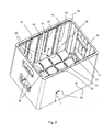
Fig. 1 zeigt eine perspektivische Ansicht eines Flaschenkastens mit einem eingesetzten Fachwerkeinsatz in einer abgesenkten Position; -
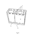
Fig. 2 zeigt den Flaschenkasten derFig. 1 ohne Fachwerkeinsatz; -
Fig. 3 zeigt eine perspektivische Ansicht eines Fachwerkeinsatzes gemäß einer ersten Ausführungsform; -
Fig. 4 zeigt eine Detailquerschnittsansicht einen Bodenabschnitts des Flaschenkastens mit dem Fachwerkeinsatz gemäß der ersten Ausführungsform; -
Fig. 5 zeigt eine perspektivische Ansicht eines Fachwerkeinsatzes gemäß einer zweiten Ausführungsform; -
Fig. 6 zeigt eine perspektivische Ansicht eines Fachwerkeinsatzes gemäß einer dritten Ausführungsform; -
Fig. 7 zeigt eine perspektivische Querschnittsansicht des Fachwerkeinsatzes gemäß der dritten Ausführungsform in einer abgesenkten Position; -
Fig. 8 zeigt eine perspektivische Querschnittsansicht des Fachwerkeinsatzes gemäß der dritten Ausführungsform in einer angehobenen und verriegelten Position; -
Fig. 9 zeigt eine perspektivische Querschnittsansicht gemäßFig. 7 mit zwei Flaschenverbünden; und -
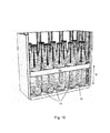
Fig. 10 zeigt eine perspektivische Querschnittsansicht gemäßFig. 8 mit Einzelflaschen
-
Fig. 1 shows a perspective view of a bottle crate with an inserted truss insert in a lowered position; -
Fig. 2 shows the bottle crate theFig. 1 without truss work; -
Fig. 3 shows a perspective view of a truss insert according to a first embodiment; -
Fig. 4 shows a detail cross-sectional view of a bottom portion of the bottle crate with the truss insert according to the first embodiment; -
Fig. 5 shows a perspective view of a truss insert according to a second embodiment; -
Fig. 6 shows a perspective view of a truss insert according to a third embodiment; -
Fig. 7 shows a perspective cross-sectional view of the truss insert according to the third embodiment in a lowered position; -
Fig. 8 shows a perspective cross-sectional view of the truss insert according to the third embodiment in a raised and locked position; -
Fig. 9 shows a perspective cross-sectional view according toFig. 7 with two bottle assemblies; and -
Fig. 10 shows a perspective cross-sectional view according toFig. 8 with single bottles
Die
Bei dem Fachwerkeinsatz 10 handelt es um ein separat zum Flaschenkasten 2 hergestelltes Bauteil, das von oben in den Flaschenkasten 2 eingesetzt und auch wieder aus diesem herausgenommen werden kann. Flaschenkasten 2 und Fachwerkeinsatz 10 können aus Kunststoff, insbesondere im Spritzgießverfahren, herstellt sein.In the
Der Fachwerkeinsatz 10 ist an den beiden gegenüberliegenden langen Seitenwänden 6 vertikal geführt und zu den beiden gegenüberliegenden kurzen Seitenwänden 8 etwas beabstandet. An der Innenseite 16 der langen Seitenwände 6 sind mehrere Führungsnuten 18, 20 und 22 ausgebildet. Diese Führungsnuten 18, 20 und 22 werden mit Bezug auf die
Die
Es ist auch möglich, dass verriegelnde Vorsprünge an einer Wandung des Flaschenkastens 2 in gegengleiche Ausnehmungen dieser Wandung zugewandten Seite des Fachwerkeinsatzes 10 vorhanden sind und dadurch das Verriegelungsprinzip umgekehrt wird. Diese Prinzipumkehr ist jedoch in den Figuren nicht wiedergegeben.It is also possible that locking projections on a wall of the
Zu beachten ist, dass die langen Führungsnuten 20 und die kurzen Führungsnuten 22 auf der gegenüberliegenden langen Seitenwand 6 genau anders herum ausgebildet sind, so dass, wenn der Fachwerkeinsatz 10 in der Ausrichtung, wie sie in der
Die langen und kurzen Führungsnuten 20, 22 sind etwas hinterschnitten und haben ein T-Profil, so dass die beispielsweise entsprechend T-förmig ausgebildeten Vorsprünge 30 in den Führungsnuten 20 und 22 zwar vertikal beweglich, aber in Querrichtung gefangen sind.. Die T-Förmigkeit ist optional und in den Figuren nicht visualisiert. Diese Führungsnuten 20 und 22 können alternativ auch rund, eckig oder schwalbenschwanzförmig ausgebildet sind. In dem gezeigten Ausführungsbeispiel laufen die langen und kurzen Führungsnuten 20, 22 nach oben offen aus. Alternativ hierzu können eine oder mehrere der Nuten 20, 22 auch oben am Flaschenkastenrand 24 geschlossen sein, so dass der Fachwerkeinsatz 10 nur durch leichtes Kippen aus dem Flaschenkasten 2 herausgenommen werden kann.The long and
Aus der
Am Flaschenkastenboden 4 sind in einer gitterförmigen Anordnung, welche der Fachwerkaufteilung des Fachwerkeinsatzes 10 entspricht, Fachwerkrippen oder Vorsprünge 36 ausgebildet, welche in den Kreuzungspunkten abgeschrägt sind und in den Flaschenkastenboden 4 übergehen. Die Fachwerkrippen 36 sind im Wesentlichen komplementär zu der Oberflächengestaltung der einen Seite des Fachwerkeinsatzes 10 (obere Seite in der
Die Einführschrägen 38 sind kreuzförmige ansteigende Rippen im Kreuzungspunkt der Fachwerkunterteilungen 40. Bei Versuch eine Flasche 14 in eine der Öffnungen 12 einzustellen, lenken zwei benachbarte Einführschrägen den Flaschenboden zur nächsten Öffnung 12.The
Die andere Seite des Fachwerkeinsatzes 10, d.h. die Unterseite in der
In der
Die
Es sei darauf hingewiesen, dass das Zusammenspiel von Nut und Vorsprung auch derart sein kann, dass die Nut am Fachwerkeinsatz vorhanden ist und der Vorsprung an einer Innenwandung des Flaschenkastens ausgebildet ist.It should be noted that the interaction of groove and projection can also be such that the groove is present on the truss insert and the projection is formed on an inner wall of the bottle crate.
Auch ist es möglich, dass ein separates Bauteil sowohl in Nuten des Fachwerkeinsatzes als auch in Nuten des Flaschenkastens eingreift.It is also possible that a separate component engages both in grooves of the truss insert as well as in grooves of the bottle crate.
In all diesen Fällen kann der Vorsprung T-förmig oder schwalbenschwanzartig ausgeformt sein. Gegengleiche Nuten ermöglichen dann einen Hinterschnitt und/oder ein Hintergreifen.In all these cases, the projection may be T-shaped or dovetail-shaped. Opposite grooves then allow an undercut and / or a grip behind.
Der in der
Die
Wenn der Fachwerkeinsatz 50 mit einer bestimmten Kraft nach oben gezogen bzw. nach unten gedrückt wird, weichen die federelastischen Verriegelungszungen 54 aus und geben den Fachwerkeinsatz 50 frei.When the
Aus der
Der Vollständigkeit halber sei erwähnt, dass es sich im Gegensatz zum Fachwerkeinsatz 10 der ersten Ausführungsform beim Fachwerkeinsatz 50 der zweiten Ausführungsform um keinen Wendefachwerkeinsatz handelt und der Fachwerkeinsatz 50 in der in der
Die
Der Fachwerkeinsatz 60 hat eine rechteckige plattenförmige Grundform, welche eine Vielzahl an Öffnungen 64 aufweist, die Flaschennester bilden. An den kurzen Seiten des Fachwerkeinsatzes 60 ist jeweils ein zur Mitte symmetrisch angeordnetes Paar von Schnappelementen 66 angeordnet, welche selbsttätig in entsprechende Ausnehmungen 68 einrasten, welche auf der Höhe H an der Innenseite der kurzen Seitenwand des Flaschenkastens 62 ausgebildet sind.The
Zum Entriegeln der Schnappelemente 66 müssen diese, wie in der
Wenn der Fachwerkeinsatz 60, wie in der
Der Fachwerkeinsatz 60 weist auf der langen Seite eine Vielzahl an Gleitflächenabschnitten 74, die an entsprechenden Innenflächenabschnitten 76 der langen Seitenwand des Flaschenkastens 62 entlang gleiten. Darüber hinaus ist der Fachwerkeinsatz 60 auch abschnittsweise an den kurzen Seiten des Flaschenkastens 62 geführt.The
Die
Bei der ersten Ausführungsform dagegen muss der Fachwerkeinsatz 10 zunächst entnommen, um 180° um die horizontale Achse A gewendet werden und wieder eingesetzt werden. Aufgrund des Zusammenwirkens der unterschiedlichen Führungspaarungen verbleibt der Fachwerkeinsatz 10 in der Höhe H, welche für den Transport der Einzelflaschen geeignet ist.In the first embodiment, however, the
Es wurden bevorzugte Ausführungsformen der Erfindung beschrieben, jedoch sind diverse Abwandlungen innerhalb des Schutzbereichs, der durch die beigefügten Ansprüche definiert wird, möglich.Preferred embodiments of the invention have been described, but various modifications are possible within the scope defined by the appended claims.
So kann beispielsweise der Fachwerkeinsatz für eine größere Anzahl kleinerer Flaschen und auch für eine kleinere Anzahl größerer Flaschen ausgelegt sein. Solange die Außenabmessungen oder zumindest die Führungsabschnitte oder Verriegelungselemente entsprechend gleich gestaltet sind, können verschiedenste Fachwerkeinsätze mit dem gleichen beschriebenen Flaschenkasten verwendet werden.Thus, for example, the truss insert can be designed for a larger number of smaller bottles and also for a smaller number of larger bottles. As long as the outer dimensions or at least the guide portions or locking elements are designed according to the same, a variety of trusses can be used with the same described bottle crate.
Der Flaschenkasten 2 der ersten Ausführungsform ist sowohl für einen Fachwerkeinsatz 10 gemäß der ersten Ausführungsform als auch für einen Fachwerkeinsatz 50 der zweiten Ausführungsform ausgelegt. Der Flaschenkasten 2 kann jedoch auch nur für jeweils eine Ausführungsform ausgelegt sein, so dass z. B. bei der Verwendung des Fachwerkeinsatzes 10 die Hauptführungsnut 18 und die Ausnehmungen 26 und 28 und bei der Verwendung eines Fachwerkeinsatzes 50 die langen und kurzen Führungsnuten 20, 22 und die Fachwerkeinsätze 36 entfallen können. Darüber hinaus können die Merkmale auch anders kombiniert sein.The
Die Führung und/oder Verrastung des Fachwerkeinsatzes 10 könnte anstatt an den Seitenwänden 6 zusätzlich oder alternative auch an sogenannten Holmen oder Pinolen mittig im Flaschenkasten erfolgen.The guide and / or locking the
Die Seiten des Wendefachwerkeinsatzes 10 der ersten Ausführungsform können auch unterschiedlich farblich gestaltet werden, um den Fachwerkeinsatz 10 entsprechend der gewünschten Verwendung leichter ausrichten zu können.The sides of the turning
In der ersten Ausführungsform erfolgt die Führung des Fachwerkeinsatzes 10 ausschließlich über die langen Seitenwände 6. Alternativ können die Führungen und die Verriegelungen auch an der kurzen Seite ausgebildet sein. Alternativ kann die Führung an den langen Seiten und die Verriegelung an den kurzen Seiten bzw. umgekehrt erfolgen.In the first embodiment, the guide of the
Claims (15)
der Fachwerkeinsatz (10) im Flaschenkasten (2) zumindest über eine bestimmte Höhe vertikal geführt ist, wobei die Führungen (20, 22, 30) von Flaschenkasten (2) und Fachwerkeinsatz (10) derart zusammenwirken, dass der in einer ersten Ausrichtung eingesetzte Fachwerkeinsatz (10) über zumindest ein erstes Führungspaar (20, 30) bis zum Flaschenkastenboden (4) absenkbar ist und in einer zu der ersten Ausrichtung gedrehten oder gewendeten zweiten Ausrichtung über zumindest ein zweites Führungspaar (22, 30) nur bis zumindest einer vom Flaschenkastenboden (4) beabstandeten vorbestimmten Höhenposition (H) absenkbar ist.Bottle crate (2) with a removable, in particular grid or plate-shaped, lattice insert (10), preferably made of plastic, for receiving bottles (14) or cans, characterized in that
the truss (10) in the bottle crate (2) is guided vertically at least over a certain height, wherein the guides (20, 22, 30) of bottle crate (2) and truss (10) cooperate such that the truss used in a first orientation (10) can be lowered to at least a first guide pair (20, 30) to the bottle case bottom (4) and in a rotated to the first orientation or second orientation about at least a second guide pair (22, 30) only to at least one of the bottle case bottom ( 4) spaced predetermined height position (H) is lowered.
das erste Führungspaar (20, 30) durch ein erstes fachwerkseitiges Führungselement (30) und ein bis zum Flaschenkastenboden (4) reichendes erstes kastenseitiges Führungselement (20) gebildet wird; und
das zweite Führungspaar (22, 30) durch das erste fachwerkseitige Führungselement (30) und ein nur bis zur vorbestimmten Höhenposition (H) reichendes zweites kastenseitiges Führungselement (22) gebildet wird.Bottle crate (2) according to one of the preceding claims, characterized in that
the first guide pair (20, 30) is formed by a first truss-side guide element (30) and a first box-side guide element (20) extending to the bottle case bottom (4); and
the second guide pair (22, 30) is formed by the first truss-side guide element (30) and a second box-side guide element (22) extending only up to the predetermined height position (H).
das erste fachwerkseitige Führungselement (30) einen an einer Umfangsseite (34) des Fachwerkeinsatzes (10) oder an einer Innenfläche einer Pinolenaufnahme des Fachwerkeinsatzes (10) ausgebildeten Führungszapfen oder -vorsprung (30) aufweist,
das erste kastenseitige Führungselement (20) eine an einer Seiteninnenwand (16) oder einer Pinole des Flaschenkastens (2) ausgebildete und bis zum Flaschenkastenboden (4) reichende erste kastenseitige Führungsnut (20) aufweist;
das zweite kastenseitige Führungselement (22) eine an einer Seiteninnenwand (16) oder einer Pinole des Flaschenkastens (2) ausgebildete und nur bis zur vorbestimmten Höhenposition (H) reichende zweite Führungsnut (22) aufweist, wobei
in der ersten Ausrichtung das Fachwerkeinsatzes (10) der fachwerkseitige Führungszapfen oder -vorsprung (30) mit der kastenseitigen ersten Führungsnut (20) zusammenwirkt oder in diese eingreift; und
in der zweiten Ausrichtung das Fachwerkeinsatzes (10) der fachwerkseitige Führungszapfen oder -vorsprung (30) mit der kastenseitigen zweiten Führungsnut (22) zusammenwirkt oder in diese eingreift.Bottle crate according to claim 3, characterized in that
the first truss-side guide element (30) has a guide pin or projection (30) formed on a peripheral side (34) of the truss insert (10) or on an inner surface of a quill receptacle of the truss insert (10),
the first box-side guide element (20) has a first box-side guide groove (20) formed on a side inner wall (16) or quill of the bottle crate (2) and extending to the bottle crate floor (4);
the second box-side guide element (22) has a second guide groove (22) formed on a side inner wall (16) or a quill of the bottle crate (2) and reaching only up to the predetermined height position (H), wherein
in the first orientation, the truss insert (10) of the truss-side guide pin or projection (30) cooperates with or engages with the box-side first guide groove (20); and
in the second orientation, the truss insert (10) of the truss-side guide pin or projection (30) cooperates with or engages in the box-side second guide groove (22).
Priority Applications (1)
| Application Number | Priority Date | Filing Date | Title |
|---|---|---|---|
| EP13177716.1A EP2829485B1 (en) | 2013-07-23 | 2013-07-23 | Bottle crate with height-adjustable framework insert |
Applications Claiming Priority (1)
| Application Number | Priority Date | Filing Date | Title |
|---|---|---|---|
| EP13177716.1A EP2829485B1 (en) | 2013-07-23 | 2013-07-23 | Bottle crate with height-adjustable framework insert |
Publications (2)
| Publication Number | Publication Date |
|---|---|
| EP2829485A1 true EP2829485A1 (en) | 2015-01-28 |
| EP2829485B1 EP2829485B1 (en) | 2017-08-30 |
Family
ID=48914054
Family Applications (1)
| Application Number | Title | Priority Date | Filing Date |
|---|---|---|---|
| EP13177716.1A Not-in-force EP2829485B1 (en) | 2013-07-23 | 2013-07-23 | Bottle crate with height-adjustable framework insert |
Country Status (1)
| Country | Link |
|---|---|
| EP (1) | EP2829485B1 (en) |
Cited By (15)
| Publication number | Priority date | Publication date | Assignee | Title |
|---|---|---|---|---|
| WO2015094708A1 (en) * | 2013-12-16 | 2015-06-25 | Poly Flex Products, Inc. | Industrial container having removable dunnage |
| EP3124390A1 (en) * | 2015-07-31 | 2017-02-01 | D.W. Plastics | Bottle crate with removable divider element |
| USD904829S1 (en) | 2018-12-11 | 2020-12-15 | Yeti Coolers, Llc | Container accessories |
| USD907445S1 (en) | 2018-12-11 | 2021-01-12 | Yeti Coolers, Llc | Container accessories |
| US11203465B2 (en) | 2017-06-12 | 2021-12-21 | Yeti Coolers, Llc | Container and latching system |
| USD946894S1 (en) | 2017-06-12 | 2022-03-29 | Yeti Coolers, Llc | Container |
| USD951643S1 (en) | 2020-06-30 | 2022-05-17 | Yeti Coolers, Llc | Luggage |
| USD954436S1 (en) | 2020-06-30 | 2022-06-14 | Yeti Coolers, Llc | Luggage |
| USD960648S1 (en) | 2020-12-16 | 2022-08-16 | Yeti Coolers, Llc | Container accessory |
| USD961926S1 (en) | 2020-06-30 | 2022-08-30 | Yeti Coolers, Llc | Luggage |
| USD963344S1 (en) | 2020-06-30 | 2022-09-13 | Yeti Coolers, Llc | Luggage |
| US11517086B2 (en) | 2019-01-06 | 2022-12-06 | Yeti Coolers, Llc | Luggage system |
| USD985937S1 (en) | 2020-12-16 | 2023-05-16 | Yeti Coolers, Llc | Container |
| US11685573B2 (en) | 2017-06-12 | 2023-06-27 | Yeti Coolers, Llc | Carry strap for container |
| USD994438S1 (en) | 2020-12-16 | 2023-08-08 | Yeti Coolers, Llc | Container |
Citations (10)
| Publication number | Priority date | Publication date | Assignee | Title |
|---|---|---|---|---|
| US2119889A (en) | 1935-05-03 | 1938-06-07 | American Steel & Wire Co | Partition |
| DE1748170U (en) | 1957-03-29 | 1957-07-04 | Schaefer Kg Fritz | USE FOR BOTTLE CRATES. |
| GB873288A (en) | 1959-02-11 | 1961-07-19 | W E Amies & Company Ltd | Improvements in crates for bottles |
| DE1839065U (en) | 1961-06-16 | 1961-10-05 | Karl Henninger | PLASTIC BOTTLE CRATE. |
| AT315724B (en) * | 1970-11-09 | 1974-06-10 | Utz Ag Georg | Stackable Harass for bottles, cans or the like. |
| US4113329A (en) * | 1977-05-12 | 1978-09-12 | Dare Pafco, Inc. | Multi-tray basket |
| US5392915A (en) * | 1993-09-03 | 1995-02-28 | Rehrig-Pacific Company, Inc. | Crate apparatus with adjustable lid |
| EP0655397A1 (en) | 1993-11-25 | 1995-05-31 | Schoeller-Plast S.A. | Bottle crate and insertable partition |
| AU716767B2 (en) * | 1996-03-06 | 2000-03-09 | Otto Plastics Pty Ltd | A crate with slidable side barrier |
| EP1637470A1 (en) | 2004-09-17 | 2006-03-22 | Berndt & Partner GmbH | Insert for a crate |
-
2013
- 2013-07-23 EP EP13177716.1A patent/EP2829485B1/en not_active Not-in-force
Patent Citations (10)
| Publication number | Priority date | Publication date | Assignee | Title |
|---|---|---|---|---|
| US2119889A (en) | 1935-05-03 | 1938-06-07 | American Steel & Wire Co | Partition |
| DE1748170U (en) | 1957-03-29 | 1957-07-04 | Schaefer Kg Fritz | USE FOR BOTTLE CRATES. |
| GB873288A (en) | 1959-02-11 | 1961-07-19 | W E Amies & Company Ltd | Improvements in crates for bottles |
| DE1839065U (en) | 1961-06-16 | 1961-10-05 | Karl Henninger | PLASTIC BOTTLE CRATE. |
| AT315724B (en) * | 1970-11-09 | 1974-06-10 | Utz Ag Georg | Stackable Harass for bottles, cans or the like. |
| US4113329A (en) * | 1977-05-12 | 1978-09-12 | Dare Pafco, Inc. | Multi-tray basket |
| US5392915A (en) * | 1993-09-03 | 1995-02-28 | Rehrig-Pacific Company, Inc. | Crate apparatus with adjustable lid |
| EP0655397A1 (en) | 1993-11-25 | 1995-05-31 | Schoeller-Plast S.A. | Bottle crate and insertable partition |
| AU716767B2 (en) * | 1996-03-06 | 2000-03-09 | Otto Plastics Pty Ltd | A crate with slidable side barrier |
| EP1637470A1 (en) | 2004-09-17 | 2006-03-22 | Berndt & Partner GmbH | Insert for a crate |
Cited By (23)
| Publication number | Priority date | Publication date | Assignee | Title |
|---|---|---|---|---|
| WO2015094708A1 (en) * | 2013-12-16 | 2015-06-25 | Poly Flex Products, Inc. | Industrial container having removable dunnage |
| EP3124390A1 (en) * | 2015-07-31 | 2017-02-01 | D.W. Plastics | Bottle crate with removable divider element |
| US11203465B2 (en) | 2017-06-12 | 2021-12-21 | Yeti Coolers, Llc | Container and latching system |
| US11685573B2 (en) | 2017-06-12 | 2023-06-27 | Yeti Coolers, Llc | Carry strap for container |
| USD946894S1 (en) | 2017-06-12 | 2022-03-29 | Yeti Coolers, Llc | Container |
| USD907445S1 (en) | 2018-12-11 | 2021-01-12 | Yeti Coolers, Llc | Container accessories |
| USD929814S1 (en) | 2018-12-11 | 2021-09-07 | Yeti Coolers, Llc | Container accessories |
| USD925991S1 (en) | 2018-12-11 | 2021-07-27 | Yeti Coolers, Llc | Container accessories |
| USD925299S1 (en) | 2018-12-11 | 2021-07-20 | Yeti Coolers, Llc | Container accessories |
| USD962010S1 (en) | 2018-12-11 | 2022-08-30 | Yeti Coolers, Llc | Divider accessory |
| USD904829S1 (en) | 2018-12-11 | 2020-12-15 | Yeti Coolers, Llc | Container accessories |
| USD959208S1 (en) | 2018-12-11 | 2022-08-02 | Yeti Coolers, Llc | Caddy accessory |
| USD960656S1 (en) | 2018-12-11 | 2022-08-16 | Yeti Coolers, Llc | Bag accessory |
| US11517086B2 (en) | 2019-01-06 | 2022-12-06 | Yeti Coolers, Llc | Luggage system |
| USD954436S1 (en) | 2020-06-30 | 2022-06-14 | Yeti Coolers, Llc | Luggage |
| USD961926S1 (en) | 2020-06-30 | 2022-08-30 | Yeti Coolers, Llc | Luggage |
| USD963344S1 (en) | 2020-06-30 | 2022-09-13 | Yeti Coolers, Llc | Luggage |
| USD951643S1 (en) | 2020-06-30 | 2022-05-17 | Yeti Coolers, Llc | Luggage |
| USD960648S1 (en) | 2020-12-16 | 2022-08-16 | Yeti Coolers, Llc | Container accessory |
| USD985937S1 (en) | 2020-12-16 | 2023-05-16 | Yeti Coolers, Llc | Container |
| USD994438S1 (en) | 2020-12-16 | 2023-08-08 | Yeti Coolers, Llc | Container |
| USD1014969S1 (en) | 2020-12-16 | 2024-02-20 | Yeti Coolers, Llc | Container |
| USD1014965S1 (en) | 2020-12-16 | 2024-02-20 | Yeti Coolers, Llc | Container |
Also Published As
| Publication number | Publication date |
|---|---|
| EP2829485B1 (en) | 2017-08-30 |
Similar Documents
| Publication | Publication Date | Title |
|---|---|---|
| EP2829485B1 (en) | Bottle crate with height-adjustable framework insert | |
| EP2829484B1 (en) | Bottle crate with height-adjustable framework insert | |
| EP0389802B1 (en) | Divisible container, especially a bottle crate | |
| DE202014103695U1 (en) | Stackable container | |
| WO2018010858A1 (en) | Stackable system container | |
| EP1157934B1 (en) | Stackable transport container | |
| EP2878550A1 (en) | Pallet | |
| EP3636559B1 (en) | Stackable box | |
| EP1733975A1 (en) | Collapsible Container | |
| EP3587294B1 (en) | Stackable container with connection mechanism | |
| DE2525169C3 (en) | Plastic bottle crate with locking device | |
| DE102019111950A1 (en) | Stackable storage unit and stack of storage units | |
| DE19713691C2 (en) | container | |
| EP0374774A2 (en) | Crates with horizontal gripping elements | |
| EP2840034A1 (en) | Latch device for locking and unlocking collapsible or folding side walls of a container | |
| DE2104389A1 (en) | Bottle crate designed as a bottle carrier and stacking crate at the same time | |
| EP0698558A2 (en) | Stackable transportcontainer | |
| EP2565130B1 (en) | Insert for a transport and storage container | |
| EP1713696B1 (en) | Storage bin | |
| DE102006016031A1 (en) | Stackable transport container | |
| DE202004016511U1 (en) | Transport and storage container for use as e.g. pay-off package, has two sets of side walls that are arranged opposite to each other, where two sets of side walls are formed in concave cross section at interior of container | |
| DE102015009734B4 (en) | Stackable single packaging | |
| DE202004014340U1 (en) | Stack nest containers | |
| EP3012205B1 (en) | Divisible crate for bottles | |
| AT413689B (en) | ZERLEGBARE BOX |
Legal Events
| Date | Code | Title | Description |
|---|---|---|---|
| 17P | Request for examination filed |
Effective date: 20130723 |
|
| AK | Designated contracting states |
Kind code of ref document: A1 Designated state(s): AL AT BE BG CH CY CZ DE DK EE ES FI FR GB GR HR HU IE IS IT LI LT LU LV MC MK MT NL NO PL PT RO RS SE SI SK SM TR |
|
| AX | Request for extension of the european patent |
Extension state: BA ME |
|
| PUAI | Public reference made under article 153(3) epc to a published international application that has entered the european phase |
Free format text: ORIGINAL CODE: 0009012 |
|
| R17P | Request for examination filed (corrected) |
Effective date: 20150629 |
|
| RBV | Designated contracting states (corrected) |
Designated state(s): AL AT BE BG CH CY CZ DE DK EE ES FI FR GB GR HR HU IE IS IT LI LT LU LV MC MK MT NL NO PL PT RO RS SE SI SK SM TR |
|
| 17Q | First examination report despatched |
Effective date: 20151116 |
|
| REG | Reference to a national code |
Ref country code: DE Ref legal event code: R079 Ref document number: 502013008189 Country of ref document: DE Free format text: PREVIOUS MAIN CLASS: B65D0001240000 Ipc: B65D0025100000 |
|
| GRAP | Despatch of communication of intention to grant a patent |
Free format text: ORIGINAL CODE: EPIDOSNIGR1 |
|
| RIC1 | Information provided on ipc code assigned before grant |
Ipc: B65D 25/10 20060101AFI20170216BHEP Ipc: B65D 1/24 20060101ALI20170216BHEP |
|
| INTG | Intention to grant announced |
Effective date: 20170310 |
|
| GRAS | Grant fee paid |
Free format text: ORIGINAL CODE: EPIDOSNIGR3 |
|
| GRAA | (expected) grant |
Free format text: ORIGINAL CODE: 0009210 |
|
| AK | Designated contracting states |
Kind code of ref document: B1 Designated state(s): AL AT BE BG CH CY CZ DE DK EE ES FI FR GB GR HR HU IE IS IT LI LT LU LV MC MK MT NL NO PL PT RO RS SE SI SK SM TR |
|
| REG | Reference to a national code |
Ref country code: GB Ref legal event code: FG4D Free format text: NOT ENGLISH |
|
| REG | Reference to a national code |
Ref country code: CH Ref legal event code: EP |
|
| REG | Reference to a national code |
Ref country code: AT Ref legal event code: REF Ref document number: 923296 Country of ref document: AT Kind code of ref document: T Effective date: 20170915 |
|
| REG | Reference to a national code |
Ref country code: IE Ref legal event code: FG4D Free format text: LANGUAGE OF EP DOCUMENT: GERMAN |
|
| REG | Reference to a national code |
Ref country code: DE Ref legal event code: R096 Ref document number: 502013008189 Country of ref document: DE |
|
| REG | Reference to a national code |
Ref country code: NL Ref legal event code: FP |
|
| REG | Reference to a national code |
Ref country code: LT Ref legal event code: MG4D |
|
| PG25 | Lapsed in a contracting state [announced via postgrant information from national office to epo] |
Ref country code: NO Free format text: LAPSE BECAUSE OF FAILURE TO SUBMIT A TRANSLATION OF THE DESCRIPTION OR TO PAY THE FEE WITHIN THE PRESCRIBED TIME-LIMIT Effective date: 20171130 Ref country code: HR Free format text: LAPSE BECAUSE OF FAILURE TO SUBMIT A TRANSLATION OF THE DESCRIPTION OR TO PAY THE FEE WITHIN THE PRESCRIBED TIME-LIMIT Effective date: 20170830 Ref country code: SE Free format text: LAPSE BECAUSE OF FAILURE TO SUBMIT A TRANSLATION OF THE DESCRIPTION OR TO PAY THE FEE WITHIN THE PRESCRIBED TIME-LIMIT Effective date: 20170830 Ref country code: LT Free format text: LAPSE BECAUSE OF FAILURE TO SUBMIT A TRANSLATION OF THE DESCRIPTION OR TO PAY THE FEE WITHIN THE PRESCRIBED TIME-LIMIT Effective date: 20170830 Ref country code: FI Free format text: LAPSE BECAUSE OF FAILURE TO SUBMIT A TRANSLATION OF THE DESCRIPTION OR TO PAY THE FEE WITHIN THE PRESCRIBED TIME-LIMIT Effective date: 20170830 |
|
| PG25 | Lapsed in a contracting state [announced via postgrant information from national office to epo] |
Ref country code: RS Free format text: LAPSE BECAUSE OF FAILURE TO SUBMIT A TRANSLATION OF THE DESCRIPTION OR TO PAY THE FEE WITHIN THE PRESCRIBED TIME-LIMIT Effective date: 20170830 Ref country code: GR Free format text: LAPSE BECAUSE OF FAILURE TO SUBMIT A TRANSLATION OF THE DESCRIPTION OR TO PAY THE FEE WITHIN THE PRESCRIBED TIME-LIMIT Effective date: 20171201 Ref country code: ES Free format text: LAPSE BECAUSE OF FAILURE TO SUBMIT A TRANSLATION OF THE DESCRIPTION OR TO PAY THE FEE WITHIN THE PRESCRIBED TIME-LIMIT Effective date: 20170830 Ref country code: LV Free format text: LAPSE BECAUSE OF FAILURE TO SUBMIT A TRANSLATION OF THE DESCRIPTION OR TO PAY THE FEE WITHIN THE PRESCRIBED TIME-LIMIT Effective date: 20170830 Ref country code: IS Free format text: LAPSE BECAUSE OF FAILURE TO SUBMIT A TRANSLATION OF THE DESCRIPTION OR TO PAY THE FEE WITHIN THE PRESCRIBED TIME-LIMIT Effective date: 20171230 Ref country code: BG Free format text: LAPSE BECAUSE OF FAILURE TO SUBMIT A TRANSLATION OF THE DESCRIPTION OR TO PAY THE FEE WITHIN THE PRESCRIBED TIME-LIMIT Effective date: 20171130 |
|
| PG25 | Lapsed in a contracting state [announced via postgrant information from national office to epo] |
Ref country code: DK Free format text: LAPSE BECAUSE OF FAILURE TO SUBMIT A TRANSLATION OF THE DESCRIPTION OR TO PAY THE FEE WITHIN THE PRESCRIBED TIME-LIMIT Effective date: 20170830 Ref country code: CZ Free format text: LAPSE BECAUSE OF FAILURE TO SUBMIT A TRANSLATION OF THE DESCRIPTION OR TO PAY THE FEE WITHIN THE PRESCRIBED TIME-LIMIT Effective date: 20170830 Ref country code: RO Free format text: LAPSE BECAUSE OF FAILURE TO SUBMIT A TRANSLATION OF THE DESCRIPTION OR TO PAY THE FEE WITHIN THE PRESCRIBED TIME-LIMIT Effective date: 20170830 Ref country code: PL Free format text: LAPSE BECAUSE OF FAILURE TO SUBMIT A TRANSLATION OF THE DESCRIPTION OR TO PAY THE FEE WITHIN THE PRESCRIBED TIME-LIMIT Effective date: 20170830 |
|
| PG25 | Lapsed in a contracting state [announced via postgrant information from national office to epo] |
Ref country code: SK Free format text: LAPSE BECAUSE OF FAILURE TO SUBMIT A TRANSLATION OF THE DESCRIPTION OR TO PAY THE FEE WITHIN THE PRESCRIBED TIME-LIMIT Effective date: 20170830 Ref country code: IT Free format text: LAPSE BECAUSE OF FAILURE TO SUBMIT A TRANSLATION OF THE DESCRIPTION OR TO PAY THE FEE WITHIN THE PRESCRIBED TIME-LIMIT Effective date: 20170830 Ref country code: EE Free format text: LAPSE BECAUSE OF FAILURE TO SUBMIT A TRANSLATION OF THE DESCRIPTION OR TO PAY THE FEE WITHIN THE PRESCRIBED TIME-LIMIT Effective date: 20170830 Ref country code: SM Free format text: LAPSE BECAUSE OF FAILURE TO SUBMIT A TRANSLATION OF THE DESCRIPTION OR TO PAY THE FEE WITHIN THE PRESCRIBED TIME-LIMIT Effective date: 20170830 |
|
| REG | Reference to a national code |
Ref country code: DE Ref legal event code: R097 Ref document number: 502013008189 Country of ref document: DE |
|
| PLBE | No opposition filed within time limit |
Free format text: ORIGINAL CODE: 0009261 |
|
| STAA | Information on the status of an ep patent application or granted ep patent |
Free format text: STATUS: NO OPPOSITION FILED WITHIN TIME LIMIT |
|
| 26N | No opposition filed |
Effective date: 20180531 |
|
| PG25 | Lapsed in a contracting state [announced via postgrant information from national office to epo] |
Ref country code: SI Free format text: LAPSE BECAUSE OF FAILURE TO SUBMIT A TRANSLATION OF THE DESCRIPTION OR TO PAY THE FEE WITHIN THE PRESCRIBED TIME-LIMIT Effective date: 20170830 |
|
| PG25 | Lapsed in a contracting state [announced via postgrant information from national office to epo] |
Ref country code: MT Free format text: LAPSE BECAUSE OF FAILURE TO SUBMIT A TRANSLATION OF THE DESCRIPTION OR TO PAY THE FEE WITHIN THE PRESCRIBED TIME-LIMIT Effective date: 20170830 |
|
| REG | Reference to a national code |
Ref country code: CH Ref legal event code: PL |
|
| GBPC | Gb: european patent ceased through non-payment of renewal fee |
Effective date: 20180723 |
|
| PG25 | Lapsed in a contracting state [announced via postgrant information from national office to epo] |
Ref country code: MC Free format text: LAPSE BECAUSE OF FAILURE TO SUBMIT A TRANSLATION OF THE DESCRIPTION OR TO PAY THE FEE WITHIN THE PRESCRIBED TIME-LIMIT Effective date: 20170830 Ref country code: LU Free format text: LAPSE BECAUSE OF NON-PAYMENT OF DUE FEES Effective date: 20180723 |
|
| REG | Reference to a national code |
Ref country code: IE Ref legal event code: MM4A |
|
| PG25 | Lapsed in a contracting state [announced via postgrant information from national office to epo] |
Ref country code: CH Free format text: LAPSE BECAUSE OF NON-PAYMENT OF DUE FEES Effective date: 20180731 Ref country code: GB Free format text: LAPSE BECAUSE OF NON-PAYMENT OF DUE FEES Effective date: 20180723 Ref country code: FR Free format text: LAPSE BECAUSE OF NON-PAYMENT OF DUE FEES Effective date: 20180731 Ref country code: LI Free format text: LAPSE BECAUSE OF NON-PAYMENT OF DUE FEES Effective date: 20180731 Ref country code: IE Free format text: LAPSE BECAUSE OF NON-PAYMENT OF DUE FEES Effective date: 20180723 |
|
| PGFP | Annual fee paid to national office [announced via postgrant information from national office to epo] |
Ref country code: NL Payment date: 20190722 Year of fee payment: 7 |
|
| REG | Reference to a national code |
Ref country code: AT Ref legal event code: MM01 Ref document number: 923296 Country of ref document: AT Kind code of ref document: T Effective date: 20180723 |
|
| PGFP | Annual fee paid to national office [announced via postgrant information from national office to epo] |
Ref country code: DE Payment date: 20190628 Year of fee payment: 7 |
|
| PGFP | Annual fee paid to national office [announced via postgrant information from national office to epo] |
Ref country code: BE Payment date: 20190722 Year of fee payment: 7 |
|
| PG25 | Lapsed in a contracting state [announced via postgrant information from national office to epo] |
Ref country code: AT Free format text: LAPSE BECAUSE OF NON-PAYMENT OF DUE FEES Effective date: 20180723 |
|
| PG25 | Lapsed in a contracting state [announced via postgrant information from national office to epo] |
Ref country code: TR Free format text: LAPSE BECAUSE OF FAILURE TO SUBMIT A TRANSLATION OF THE DESCRIPTION OR TO PAY THE FEE WITHIN THE PRESCRIBED TIME-LIMIT Effective date: 20170830 |
|
| PG25 | Lapsed in a contracting state [announced via postgrant information from national office to epo] |
Ref country code: HU Free format text: LAPSE BECAUSE OF FAILURE TO SUBMIT A TRANSLATION OF THE DESCRIPTION OR TO PAY THE FEE WITHIN THE PRESCRIBED TIME-LIMIT; INVALID AB INITIO Effective date: 20130723 Ref country code: PT Free format text: LAPSE BECAUSE OF FAILURE TO SUBMIT A TRANSLATION OF THE DESCRIPTION OR TO PAY THE FEE WITHIN THE PRESCRIBED TIME-LIMIT Effective date: 20170830 |
|
| PG25 | Lapsed in a contracting state [announced via postgrant information from national office to epo] |
Ref country code: MK Free format text: LAPSE BECAUSE OF NON-PAYMENT OF DUE FEES Effective date: 20170830 Ref country code: CY Free format text: LAPSE BECAUSE OF FAILURE TO SUBMIT A TRANSLATION OF THE DESCRIPTION OR TO PAY THE FEE WITHIN THE PRESCRIBED TIME-LIMIT Effective date: 20170830 |
|
| PG25 | Lapsed in a contracting state [announced via postgrant information from national office to epo] |
Ref country code: AL Free format text: LAPSE BECAUSE OF FAILURE TO SUBMIT A TRANSLATION OF THE DESCRIPTION OR TO PAY THE FEE WITHIN THE PRESCRIBED TIME-LIMIT Effective date: 20170830 |
|
| REG | Reference to a national code |
Ref country code: DE Ref legal event code: R119 Ref document number: 502013008189 Country of ref document: DE |
|
| REG | Reference to a national code |
Ref country code: NL Ref legal event code: MM Effective date: 20200801 |
|
| REG | Reference to a national code |
Ref country code: BE Ref legal event code: MM Effective date: 20200731 |
|
| PG25 | Lapsed in a contracting state [announced via postgrant information from national office to epo] |
Ref country code: NL Free format text: LAPSE BECAUSE OF NON-PAYMENT OF DUE FEES Effective date: 20200801 |
|
| PG25 | Lapsed in a contracting state [announced via postgrant information from national office to epo] |
Ref country code: BE Free format text: LAPSE BECAUSE OF NON-PAYMENT OF DUE FEES Effective date: 20200731 Ref country code: DE Free format text: LAPSE BECAUSE OF NON-PAYMENT OF DUE FEES Effective date: 20210202 |