EP2829477B1 - Machine de remplissage rotative - Google Patents
Machine de remplissage rotative Download PDFInfo
- Publication number
- EP2829477B1 EP2829477B1 EP13382300.5A EP13382300A EP2829477B1 EP 2829477 B1 EP2829477 B1 EP 2829477B1 EP 13382300 A EP13382300 A EP 13382300A EP 2829477 B1 EP2829477 B1 EP 2829477B1
- Authority
- EP
- European Patent Office
- Prior art keywords
- displacement
- joined
- spindle
- package
- filling
- Prior art date
- Legal status (The legal status is an assumption and is not a legal conclusion. Google has not performed a legal analysis and makes no representation as to the accuracy of the status listed.)
- Active
Links
Images


Classifications
-
- B—PERFORMING OPERATIONS; TRANSPORTING
- B65—CONVEYING; PACKING; STORING; HANDLING THIN OR FILAMENTARY MATERIAL
- B65B—MACHINES, APPARATUS OR DEVICES FOR, OR METHODS OF, PACKAGING ARTICLES OR MATERIALS; UNPACKING
- B65B43/00—Forming, feeding, opening or setting-up containers or receptacles in association with packaging
- B65B43/42—Feeding or positioning bags, boxes, or cartons in the distended, opened, or set-up state; Feeding preformed rigid containers, e.g. tins, capsules, glass tubes, glasses, to the packaging position; Locating containers or receptacles at the filling position; Supporting containers or receptacles during the filling operation
- B65B43/50—Feeding or positioning bags, boxes, or cartons in the distended, opened, or set-up state; Feeding preformed rigid containers, e.g. tins, capsules, glass tubes, glasses, to the packaging position; Locating containers or receptacles at the filling position; Supporting containers or receptacles during the filling operation using rotary tables or turrets
-
- B—PERFORMING OPERATIONS; TRANSPORTING
- B65—CONVEYING; PACKING; STORING; HANDLING THIN OR FILAMENTARY MATERIAL
- B65B—MACHINES, APPARATUS OR DEVICES FOR, OR METHODS OF, PACKAGING ARTICLES OR MATERIALS; UNPACKING
- B65B3/00—Packaging plastic material, semiliquids, liquids or mixed solids and liquids, in individual containers or receptacles, e.g. bags, sacks, boxes, cartons, cans, or jars
- B65B3/04—Methods of, or means for, filling the material into the containers or receptacles
- B65B3/10—Methods of, or means for, filling the material into the containers or receptacles by application of pressure to material
- B65B3/12—Methods of, or means for, filling the material into the containers or receptacles by application of pressure to material mechanically, e.g. by pistons or pumps
-
- B—PERFORMING OPERATIONS; TRANSPORTING
- B65—CONVEYING; PACKING; STORING; HANDLING THIN OR FILAMENTARY MATERIAL
- B65B—MACHINES, APPARATUS OR DEVICES FOR, OR METHODS OF, PACKAGING ARTICLES OR MATERIALS; UNPACKING
- B65B43/00—Forming, feeding, opening or setting-up containers or receptacles in association with packaging
- B65B43/42—Feeding or positioning bags, boxes, or cartons in the distended, opened, or set-up state; Feeding preformed rigid containers, e.g. tins, capsules, glass tubes, glasses, to the packaging position; Locating containers or receptacles at the filling position; Supporting containers or receptacles during the filling operation
- B65B43/54—Means for supporting containers or receptacles during the filling operation
- B65B43/60—Means for supporting containers or receptacles during the filling operation rotatable
- B65B43/62—Means for supporting containers or receptacles during the filling operation rotatable about an axis located at the filling position, e.g. the axis of the container or receptacle
-
- B—PERFORMING OPERATIONS; TRANSPORTING
- B65—CONVEYING; PACKING; STORING; HANDLING THIN OR FILAMENTARY MATERIAL
- B65B—MACHINES, APPARATUS OR DEVICES FOR, OR METHODS OF, PACKAGING ARTICLES OR MATERIALS; UNPACKING
- B65B39/00—Nozzles, funnels or guides for introducing articles or materials into containers or wrappers
- B65B2039/009—Multiple outlets
-
- B—PERFORMING OPERATIONS; TRANSPORTING
- B65—CONVEYING; PACKING; STORING; HANDLING THIN OR FILAMENTARY MATERIAL
- B65B—MACHINES, APPARATUS OR DEVICES FOR, OR METHODS OF, PACKAGING ARTICLES OR MATERIALS; UNPACKING
- B65B3/00—Packaging plastic material, semiliquids, liquids or mixed solids and liquids, in individual containers or receptacles, e.g. bags, sacks, boxes, cartons, cans, or jars
- B65B3/26—Methods or devices for controlling the quantity of the material fed or filled
- B65B3/30—Methods or devices for controlling the quantity of the material fed or filled by volumetric measurement
Definitions
- the present invention refers to a rotary filling machine, which offers a large number of benefits in the packaging of monophase and multiphase products, at the level of medium and high speed industrial production.
- the present invention has been especially designed to be applied to high and medium speed packaging lines in general, which is particularly suited to the packaging of cosmetic, alimentary, pharmaceutical or other home cleaning products, amongst others.
- New forms of presentation bestow various benefits on the packaged products, at both aesthetic and operational level.
- Aesthetic benefits are particularly relevant, making said products more commercially attractive within an increasingly demanding and selective market.
- Operational benefits mainly relate to a suitable way of using the product, enabling the various compositions from which it is formed to be conveniently mixed, in order to achieve the optimal effect expected from the same.
- inline fillers in which all filling stations are aligned and parallel to the production line. These machines only facilitate low and medium speed production, with a maximum of 150 units being produced per minute. These machines operate in an indexing manner. In other words, the various operations or stages (loading packages, filling, unloading packages etc.,) involved are carried out intermittently according to a sequential order. In turn, this simplifies the number of mechanisms and controls, which is why, within the range of speeds within which work can be carried out, it is usually the most profitable option.
- the rotary filling machines consist of a filling carrousel, in which the various filling stations, with their corresponding dosage means, are located in the same diameter. Said carrousel rotates constantly.
- the packages are introduced from the production line to the filling carrousel, known as an "infeed starwheel”. The packages are thus deposited on a base, which can be displaced in the direction of a vertical axis. Once the process has come to an end, the packages are extracted from the carrousel by means of an "outfeed starwheel". Both starwheels rotate in synchronisation with the filling carrousel and are tangent with the production line.
- a machine formed in a production line in this way is capable of reaching very high speeds (1000 units per minute).
- the main advantage of it stems from the fact that the package always moves at a constant speed and the machine maintains a constant rotational movement, thus preventing the packages from stopping or being removed alongside the problems resulting in the event of demanding high speeds from inline fillers.
- the rotary filling machine object of the present invention, resolves the problems set out above, via a formation which amplifies the relative movements between the package and the dosage means, thus achieving medium and high speed levels of industrial production and a greater number of benefits in the packaging of monophase and multiphase products. It may, for example, improve the distribution of a monophase product, exerting a centrifugal force on the same or create a countless number of filling patterns for a multiphase product in a package.
- the rotary filling machine, object of the present invention is of the variety comprising:
- each filling station comprises:
- the carrousel preferably comprises:
- the dosage means are preferably configured to administer the dosages of a product, formed by a plurality of compositions, which are supplied separately, it being possible to have two, three, four or more compositions.
- said dosage means comprise:
- the measuring units are charged with measuring the amount of each composition to be filled at each instant or moment of the process.
- Those which use dosage cylinders or other positive displacement dosage pumps are amongst the most common, in addition to those which use flow meters.
- the first kind measure the flow by calculating the volume displaced by said positive displacement pumps, for example, the displacement of a piston within a dosage cylinder is known, as well as the volume displaced by the same. In these cases, the pump regulation is carried out by regulating the speed of the corresponding positive displacement pump.
- the second type use flow meters to measure the flow, whilst they are regulated by means of proportional valves. In order to increase the pressure, closed-loop controls are usually applied between the flow meter and the aperture or close of the proportional valve.
- the dosage means preferably comprise a final flexible channel for each composition, configured to facilitate the displacement of the filling head piece on the horizontal plane.
- the rotation means are configured to rotate the package on the carrousel, comprising:
- the vertical bar is arranged perpendicularly between the first disc and second disc, joined to the same via a first lower tread element and a first upper tread element respectively, whilst the rotation mechanism comprises:
- the vertical displacement means preferably comprise:
- the elevator spindle is arranged perpendicularly between the first disc and second disc, joined to the same via a second lower tread element and a second upper tread element, respectively, whilst the vertical transfer cart is joined to the vertical bar.
- the elevator mechanism comprises:
- the horizontal displacement means are preferably based on the movement of the filling head piece of the dosage means on the horizontal plane, the package remaining fixed on said plane.
- the horizontal displacement means comprise:
- the horizontal displacement means comprise:
- the lateral transfer cart is preferably joined to the carrousel and to the front transfer cart, whilst said front transfer cart is joined to the filling head piece.
- the horizontal displacement means are based on the movement of the package on the horizontal plane, the dosage means remaining fixed.
- control means of the machine, object of the present invention comprise all automatisms, visualisation devices and devices for introducing operational information, process hardware and software necessary for correct operation and functioning of the method and apparatus of the present invention.
- the machine, object of the present invention makes it possible to perform various movements, namely rotating the package, vertical displacement (Z) and horizontal displacement (X and Y), either simultaneously or alternately. That is to say, depending on the complexity of the filling pattern, any of the following groups of movements may be required in order to obtain it:
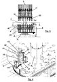
- Figures 1, 2 and 3 are a perspective, plan and profile view, respectively of the machine (1), object of the present invention.
- the rotary filling machine object of the present invention is of the variety comprising:
- each filling station (5) comprises:
- a lower portion of the filling station (5) is arranged on a lower portion of the carrousel (6), which in accordance with the present example, comprises:
- An upper portion of the filling station (5) is arranged on an upper portion of the carrousel (6), which in accordance with the present example, comprises:
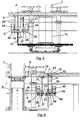
- FIGS 4 , 5 and 6 illustrate the rotation means (40) and vertical displacement means (60) of a filling station (5) in more detail.
- the rotation means (40) are configured to rotate the package (2) on the carrousel (6), comprising:
- the vertical bar (41) is arranged perpendicularly between the first disc (8) and the second disc (9), joined to the same via a first lower tread element (51) and a first upper tread element (52), respectively, whilst the rotation mechanism (44), comprises:
- the vertical displacement means (20) comprise:
- the elevator spindle (21) is arranged perpendicularly between the first disc (8) and the second disc (9), joined to the same via a second lower tread element (31) and a second upper tread element (32) respectively, whilst the vertical transfer cart (23) is joined to the vertical bar (41).
- the elevator mechanism (24) comprises:
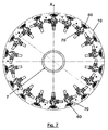
- Figure 7 shows how the filling stations (5) are arranged in relation to the carrousel (6), wherein the dosage means (60) and horizontal displacement means (70) can be observed.
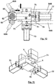
- FIGs 8 and 9 are more detailed representations of the dosage means (60). As can be seen, they are configured to administer the dosage of a product (100), formed by a plurality of compositions (100A, 100B), which are supplied separately (see Figures 12A and 13A ).
- the dosage means (60) comprise:
- the dosage means (60) comprise a final flexible channel (65A, 65B) for each composition (100A, 100B), configured to facilitate the displacement of the filling head piece (62) on the horizontal plane (XY).
- Figures 10 and 11 represent the horizontal displacement (70) in greater detail. As can be seen, in accordance with the present example, they are based on the movement of the filling head piece (62) of the dosage means (60) on the horizontal plane (XY), the package (2) remaining fixed on said plane.
- the horizontal displacement means (70) comprise:
- the horizontal displacement means (70) comprise:
- the lateral transfer cart (72) is preferably joined to the carrousel (6) and to the front transfer cart (76), whilst said front transfer cart (76) is joined to the filling head piece (62).
- Figure 12A is a front schematic view of the generation of a first example of a filling pattern. Arrows have been used in this figure to indicate the direction of all of the movements involved in generating it.
- the filling pattern has a first composition (100A) with a helical form variable diameter, along the length of the package (2), absorbed in a second composition (100B).
- the relative vertical distance (dZ) between the package (2) and the output mouthpiece (63) in the direction of the vertical axis (Z) varies from the bottom of the package (2) to beyond its mouth, according to the level represented in said figure.
- Figure 12C is a lateral view of the result obtained using this first example of a filling pattern.
- Figure 13A is a front schematic view of the generation of a second example of a filling pattern (100). Arrows are contained therein in order to represent the direction of all the movements involved in generating it.
- the filling pattern has a first composition (100B), divided into at least two parts absorbed in a second composition (100A).
- the relative vertical distance (dZ) between the package (2) and the output mouthpiece (63) in the direction of the vertical axis (Z) varies from the bottom of the package (2) to beyond its mouth, according to the level shown in said figure.
- Figure 13C is a side view of the result obtained using this second example of a filling pattern.
Landscapes
- Engineering & Computer Science (AREA)
- Mechanical Engineering (AREA)
- Auxiliary Devices For And Details Of Packaging Control (AREA)
- Basic Packing Technique (AREA)
- Filling Of Jars Or Cans And Processes For Cleaning And Sealing Jars (AREA)
Claims (12)
- Machine de remplissage rotative, comprenant :• une étoile d'entrée rotative (3) configurée pour fournir des paquets (2) ;• un carrousel de remplissage rotatif (6) sur lequel une pluralité de stations de remplissage (5) sont disposées diamétralement à celui-ci, chacune desquelles est configurée pour recevoir un paquet (2) provenant de l'étoile d'entrée (3), dans lequel chaque station de remplissage (5) comprend :• des moyens de dosage (60) configurés pour administrer le dosage d'un produit (100) à l'intérieur du paquet (2) ;• des moyens de déplacement vertical (20) configurés pour varier la distance relative entre le paquet (2) et les moyens de dosage (60) dans la direction d'un axe vertical (Z) et ;• des moyens de rotation (40), configurés pour fournir un mouvement de rotation relative (R) entre le paquet (2) et les moyens de dosage (60), autour de l'axe vertical (Z), dans laquelle les moyens de rotation (40) sont configurés pour faire tourner le paquet (2) par rapport au carrousel (6) ; et• une étoile de sortie rotative (4), configurée pour retirer les paquets (2) du carrousel de remplissage (6), dans laquelle aussi bien les étoiles d'entrée (3) que de sortie (4) sont configurées pour tourner en synchronisation avec le carrousel de remplissage (6) ;ladite machine (1) étant caractérisée en ce que chaque station de remplissage (5) comprend :• des moyens de déplacement horizontal (70) configurés pour varier la distance relative entre le paquet (2) et les moyens de dosage (60) sur un plan horizontal (XY) perpendiculaire à l'axe vertical (Z) ;et en ce que les moyens de rotation (40) comprennent :• une barre verticale (41) reliée au carrousel (6), qui est coaxiale à l'axe vertical (Z) et a de la liberté de rotation axiale ;• une base de rotation (43) disposée sur une extrémité supérieur (42) de la barre vertical (41), configurée pour recevoir un paquet (2) provenant de l'étoile d'entrée (3) et ;• un mécanisme de rotation (44), configuré pour faire tourner la barre verticale (41).
- Machine de remplissage rotative selon la revendication 1, caractérisée en ce que le carrousel (6) comprend :• une colonne rotative centrale (7) et ;• un premier (8) et deuxième (9) disques, concentriques à la colonne centrale (7) et reliés à celle-ci, disposés de manière à être parallèles dans une portion inférieure (7L) de ladite colonne.
- Machine de remplissage rotative selon l'une quelconque des revendications 1 à 2, caractérisée en ce que les moyens de dosage (60) sont configurés pour administrer le dosage d'un produit (100) constitué par une pluralité de compositions (100A, 100B) qui sont fournies séparément.
- Machine de remplissage rotative selon la revendication 3, caractérisée en ce que les moyens de dosage (60) comprennent :• une unité de mesure (61A, 61 B) pour chaque composition (100A, 100B), configuré pour réguler l'écoulement de celle-ci ;• une pièce de tête de remplissage (62), qui a un embout de sortie (63), configurée pour administrer le dosage de chaque composition (100A, 100B) et qui est orientée vers l'embouchure du paquet (2) et ;• un canal de distribution (64A, 64B) pour chaque composition (100A, 100B) configuré pour distribuer l'écoulement à l'unité de mesure (61A, 61 B).
- Machine de remplissage rotative selon la revendication 4, caractérisée en ce que les moyens de dosage (60) comprennent un canal flexible final (65A, 65B) pour chaque composition (100A, 100B), configuré pour faciliter le déplacement de la pièce de tête de remplissage (62) sur le plan horizontal (XY).
- Machine de remplissage rotative selon la revendication 2, caractérisée en ce que la barre verticale (41) est disposée perpendiculairement entre le premier disque (8) et le deuxième disque (9), reliée à ceux-ci par un premier élément à bande de roulement inférieur (51) et un premier élément à bande de roulement supérieur (52), respectivement et également caractérisée en ce que le mécanisme de rotation (44) comprend :• un mécanisme d'entrainement en rotation (45) qui est relié au premier disque (8) ;• une première roue motrice (46) actionnée par le mécanisme d'entrainement en rotation (45) et ;• une première roue menée (47) concentrique à la barre verticale (41) et reliée à celle-ci, qui s'engage à la première roue motrice (46) par une première courroie de transmission (48), dans laquelle la première roue motrice (46) et la première roue menée (47) sont disposées sous ledit premier disque (8).
- Dispositif de remplissage rotatif selon l'une quelconque des revendications 1 à 6, caractérisé en ce que les moyens de déplacement vertical (20) comprennent :• une broche élévatrice (21) reliée au carrousel (6), qui est parallèle à l'axe vertical (Z) et a de la liberté de rotation axiale ;• un chariot de transfert vertical (23), traversé par la broche élévatrice (21), qui peut être déplacé le long de sa longueur, dont le déplacement est transmis au paquet (2) et ;• un mécanisme d'élévation (24) configuré pour faire tourner la broche élévatrice (21) et qui donne lieu au déplacement contrôlé du chariot de transfert vertical (23) le long de la longueur de ladite broche élévatrice (21).
- Machine de remplissage rotative selon les revendications 2 et 7, caractérisée en ce que la broche élévatrice (21) est disposée perpendiculairement entre le premier disque (8) et le deuxième disque (9), reliée à ceux-ci par un deuxième élément à bande de roulement inférieur (31) et un deuxième élément à bande de roulement supérieur (32) respectivement et caractérisée en ce que le chariot de transfert vertical (23) est relié à la barre verticale (41).
- Machine de remplissage rotative selon la revendication 8, caractérisée en ce que le mécanisme d'élévation (24) comprend :• un mécanisme d'entrainement en élévation (25), qui est relié au premier disque (8) ;• une deuxième roue motrice (226), actionnée par le mécanisme d'entrainement en élévation (25) ;• une deuxième roue menée (27) concentrique à la broche élévatrice (21) et reliée à celle-ci, qui s'engage à la première roue motrice (26), par une deuxième courroie de transmission (28), dans laquelle la deuxième roue motrice (26) et la deuxième roue menée (27) sont disposées sous ledit premier disque (8) et ;• une barre de guidage (29), qui est disposée perpendiculairement entre le premier disque (8) et le deuxième disque (9), de manière à être reliée à ceux-ci, traversée par le chariot de transfert vertical (23), afin de guider son déplacement.
- Machine de remplissage rotative selon l'une quelconque des revendications 4 à 5, caractérisée en ce que les moyens de déplacement horizontal (70) comprennent :• une broche latérale (71) parallèle à l'axe Y du plan horizontal (XY) ;• un chariot de transfert latéral (72) traversé par la broche latérale (71), qui peut se déplacer le long de sa longueur et dont le déplacement est transféré à la pièce de tête de remplissage (62) des moyens de dosage (60) et ;• un mécanisme de déplacement latéral (73), configuré pour faire tourner la broche latérale (71) et donner lieu au déplacement contrôlé du chariot de transfert latéral (72) le long de la longueur de ladite broche latérale (71).
- Machine de remplissage rotative selon la revendication 10, caractérisée en ce que les moyens de déplacement horizontal (70) comprennent :• une broche avant (75) parallèle à l'axe X du plan horizontal (XY) ;• un chariot de transfert avant (76), traversé par la broche latérale (75) qui peut être déplacée le long de sa longueur, dont le déplacement est transféré à la pièce de tête de remplissage des moyens de dosage (60) et ;• un mécanisme de déplacement avant (77) configuré pour faire tourner la broche avant (75) et donner lieu au déplacement contrôlée du chariot de transfert avant (76) le long de la longueur de ladite broche avant (75).
- Machine de remplissage rotative selon la revendication 11, caractérisée en ce que le chariot de transfert latéral (72) est relié au carrousel (6) et au chariot de transfert avant (76) et caractérisée en ce que ledit chariot de transfert avant (76) est relié à la pièce de tête de remplissage (62).
Priority Applications (6)
| Application Number | Priority Date | Filing Date | Title |
|---|---|---|---|
| EP13382300.5A EP2829477B1 (fr) | 2013-07-24 | 2013-07-24 | Machine de remplissage rotative |
| PL13382300.5T PL2829477T3 (pl) | 2013-07-24 | 2013-07-24 | Maszyna napełniająca rotacyjna |
| DK13382300.5T DK2829477T3 (en) | 2013-07-24 | 2013-07-24 | Rotary Filling machine |
| ES13382300.5T ES2583013T3 (es) | 2013-07-24 | 2013-07-24 | Máquina rotativa de llenado |
| CA2857137A CA2857137A1 (fr) | 2013-07-24 | 2014-07-18 | Machine rotative de remplissage |
| US14/339,973 US9567123B2 (en) | 2013-07-24 | 2014-07-24 | Rotary filling machine |
Applications Claiming Priority (1)
| Application Number | Priority Date | Filing Date | Title |
|---|---|---|---|
| EP13382300.5A EP2829477B1 (fr) | 2013-07-24 | 2013-07-24 | Machine de remplissage rotative |
Publications (2)
| Publication Number | Publication Date |
|---|---|
| EP2829477A1 EP2829477A1 (fr) | 2015-01-28 |
| EP2829477B1 true EP2829477B1 (fr) | 2016-04-27 |
Family
ID=49486422
Family Applications (1)
| Application Number | Title | Priority Date | Filing Date |
|---|---|---|---|
| EP13382300.5A Active EP2829477B1 (fr) | 2013-07-24 | 2013-07-24 | Machine de remplissage rotative |
Country Status (6)
| Country | Link |
|---|---|
| US (1) | US9567123B2 (fr) |
| EP (1) | EP2829477B1 (fr) |
| CA (1) | CA2857137A1 (fr) |
| DK (1) | DK2829477T3 (fr) |
| ES (1) | ES2583013T3 (fr) |
| PL (1) | PL2829477T3 (fr) |
Families Citing this family (9)
| Publication number | Priority date | Publication date | Assignee | Title |
|---|---|---|---|---|
| US10524980B2 (en) * | 2016-09-13 | 2020-01-07 | Vanrx Pharmasystems, Inc. | Apparatus and method for aseptically filling pharmaceutical containers with a pharmaceutical fluid using rotary stage |
| ES2879295T3 (es) * | 2017-04-28 | 2021-11-22 | Volpak Sau | Una máquina de envasado automática para llenar una bolsa hecha de un material termosellable con una dosis de un producto suelto |
| US10919750B2 (en) | 2017-06-06 | 2021-02-16 | Pacific Packaging Machinery, Llc | Rotary filling machine |
| IT202000018850A1 (it) * | 2020-07-31 | 2022-01-31 | Gd Spa | Unità e metodo di movimentazione e riempimento di un contenitore ed apparato di produzione di articoli ad essi correlati |
| CN112607074B (zh) * | 2020-12-15 | 2023-04-28 | 安徽中一智能科技有限公司 | 高速包装机的液体物料自动定量输出机构 |
| CN114348353B (zh) * | 2021-12-06 | 2024-03-01 | 湖南浩森胶业有限公司 | 一种速粘胶包装熔接系统 |
| CN117775362A (zh) * | 2022-12-02 | 2024-03-29 | 周淑叶 | 一种采样试管灌装装置 |
| CN117775363B (zh) * | 2024-01-30 | 2026-03-27 | 中博瑞康(上海)生物技术有限公司 | 一种细胞液的分装方法 |
| CN117885960B (zh) * | 2024-01-24 | 2025-12-26 | 楚天科技股份有限公司 | 一种粉体填充机构 |
Family Cites Families (12)
| Publication number | Priority date | Publication date | Assignee | Title |
|---|---|---|---|---|
| US3892264A (en) * | 1973-10-10 | 1975-07-01 | Federal Manufacturing Company | Method and apparatus for filling bottles |
| US4159028A (en) * | 1977-03-28 | 1979-06-26 | Almay, Inc. | Method of forming and containerizing a multiphase cosmetic composition |
| US4966205A (en) * | 1988-02-02 | 1990-10-30 | Pola Chemical Industries Ltd. | Method and apparatus for charging transparent material |
| DE59800608D1 (de) * | 1997-08-18 | 2001-05-17 | Benhil Gasti Verpackungsmaschi | Vorrichtung und Verfahren zum dosierten Abfüllen von flüssigen bis pastösen Produkten |
| US6065508A (en) * | 1998-11-06 | 2000-05-23 | Pneumatic Scale Corporation | Filler product supply apparatus and method |
| US6516838B2 (en) * | 1999-07-28 | 2003-02-11 | Patrick Thibiant | Apparatus and process for forming novel spiral compositions |
| ATE294739T1 (de) * | 2002-09-26 | 2005-05-15 | Tecniche Costec S R L Costruzi | Drehtischfüllmaschine |
| CN1780601B (zh) * | 2003-05-01 | 2010-05-12 | 宝洁公司 | 在视觉上截然不同的多液相组合物 |
| DE102006033511A1 (de) * | 2006-07-20 | 2008-01-24 | Khs Ag | Behandlungsmaschine |
| WO2010101576A1 (fr) * | 2009-03-06 | 2010-09-10 | Colgate-Palmolive Company | Appareil et procédé pour le remplissage d'un récipient avec au moins deux composants d'une composition |
| US8386072B1 (en) * | 2009-04-20 | 2013-02-26 | Pneumatic Scale Corporation | Dual meter filler apparatus and method |
| DK2639163T3 (en) * | 2012-03-15 | 2014-12-08 | Antonio Mengibar S A | Method and apparatus for generating a filling pattern for filling containers |
-
2013
- 2013-07-24 EP EP13382300.5A patent/EP2829477B1/fr active Active
- 2013-07-24 PL PL13382300.5T patent/PL2829477T3/pl unknown
- 2013-07-24 DK DK13382300.5T patent/DK2829477T3/en active
- 2013-07-24 ES ES13382300.5T patent/ES2583013T3/es active Active
-
2014
- 2014-07-18 CA CA2857137A patent/CA2857137A1/fr not_active Abandoned
- 2014-07-24 US US14/339,973 patent/US9567123B2/en active Active
Also Published As
| Publication number | Publication date |
|---|---|
| US9567123B2 (en) | 2017-02-14 |
| DK2829477T3 (en) | 2016-08-15 |
| CA2857137A1 (fr) | 2015-01-24 |
| EP2829477A1 (fr) | 2015-01-28 |
| ES2583013T3 (es) | 2016-09-16 |
| US20150027585A1 (en) | 2015-01-29 |
| PL2829477T3 (pl) | 2016-10-31 |
Similar Documents
| Publication | Publication Date | Title |
|---|---|---|
| EP2829477B1 (fr) | Machine de remplissage rotative | |
| CA2808954C (fr) | Procede et appareil permettant de generer un schema de remplissage pour le remplissage de contenants | |
| RU2474531C2 (ru) | Система многоструйного заполнения емкостей | |
| DE60336462D1 (de) | Abfüllmachine für Kapseln | |
| CN104276537B (zh) | 高速灌装旋盖系统 | |
| DE602009000746D1 (de) | Gerät zum Zubereiten und Verteilen von Infusionsprodukte, insbesondere Kaffee, in veränderbaren volumetrischen Mengen | |
| CN103754411A (zh) | 全自动纸盒开装封贴带一体机 | |
| RU2706626C2 (ru) | Способ изготовления наполненного и закрытого контейнера, устройство для осуществления способа и контейнер, изготовленный указанным способом | |
| EP3386903B1 (fr) | Tireuse comprenant au moins deux micro-caroussels pour fluides additifs et procédé correspondant | |
| CN103342327A (zh) | 颗粒香辣酱称量灌装生产线 | |
| CN202807126U (zh) | 一种版块式物料连续高速装盒机 | |
| CN202704022U (zh) | 安瓿瓶自动印字入托装置 | |
| CN203698739U (zh) | 全自动纸盒开装封贴带一体机 | |
| CN106697397B (zh) | 定向旋转送版装置 | |
| CN106586110A (zh) | 转瓶机构及其无损伤进瓶装置 | |
| CN104309825A (zh) | 颗粒胶囊包装机 | |
| CN202848049U (zh) | 一种定量药品包装装置 | |
| CN206151877U (zh) | 一种双动式胶囊加药装置 | |
| CN203486192U (zh) | 多规格易更换双位装箱理料机 | |
| ITMN20080015A1 (it) | Dispositivo di riempimento di contenitori mediante un prodotto contenente un componente principale ed almeno un componente additivo variabile. | |
| CN105857790A (zh) | 一种粉剂灌装机不等速进出瓶传动机构 | |
| CN204623874U (zh) | 电磁离合器控制式螺杆计量装置 | |
| CN202080458U (zh) | 注射器摆料机的工件输送机构 | |
| CN103448945B (zh) | 多规格易更换双位装箱理料机 | |
| CN105292529A (zh) | 一种药品包装机械 |
Legal Events
| Date | Code | Title | Description |
|---|---|---|---|
| 17P | Request for examination filed |
Effective date: 20130724 |
|
| AK | Designated contracting states |
Kind code of ref document: A1 Designated state(s): AL AT BE BG CH CY CZ DE DK EE ES FI FR GB GR HR HU IE IS IT LI LT LU LV MC MK MT NL NO PL PT RO RS SE SI SK SM TR |
|
| AX | Request for extension of the european patent |
Extension state: BA ME |
|
| PUAI | Public reference made under article 153(3) epc to a published international application that has entered the european phase |
Free format text: ORIGINAL CODE: 0009012 |
|
| R17P | Request for examination filed (corrected) |
Effective date: 20150622 |
|
| RBV | Designated contracting states (corrected) |
Designated state(s): AL AT BE BG CH CY CZ DE DK EE ES FI FR GB GR HR HU IE IS IT LI LT LU LV MC MK MT NL NO PL PT RO RS SE SI SK SM TR |
|
| REG | Reference to a national code |
Ref country code: DE Ref legal event code: R079 Ref document number: 602013006980 Country of ref document: DE Free format text: PREVIOUS MAIN CLASS: B65B0003040000 Ipc: B65B0003120000 |
|
| GRAP | Despatch of communication of intention to grant a patent |
Free format text: ORIGINAL CODE: EPIDOSNIGR1 |
|
| RIC1 | Information provided on ipc code assigned before grant |
Ipc: B65B 3/12 20060101AFI20151021BHEP Ipc: B65B 43/60 20060101ALI20151021BHEP Ipc: B65B 43/50 20060101ALI20151021BHEP Ipc: B65B 39/00 20060101ALN20151021BHEP Ipc: B65B 3/30 20060101ALN20151021BHEP |
|
| RIC1 | Information provided on ipc code assigned before grant |
Ipc: B65B 39/00 20060101ALN20151112BHEP Ipc: B65B 43/50 20060101ALI20151112BHEP Ipc: B65B 3/12 20060101AFI20151112BHEP Ipc: B65B 43/60 20060101ALI20151112BHEP Ipc: B65B 3/30 20060101ALN20151112BHEP |
|
| INTG | Intention to grant announced |
Effective date: 20151126 |
|
| GRAS | Grant fee paid |
Free format text: ORIGINAL CODE: EPIDOSNIGR3 |
|
| GRAA | (expected) grant |
Free format text: ORIGINAL CODE: 0009210 |
|
| AK | Designated contracting states |
Kind code of ref document: B1 Designated state(s): AL AT BE BG CH CY CZ DE DK EE ES FI FR GB GR HR HU IE IS IT LI LT LU LV MC MK MT NL NO PL PT RO RS SE SI SK SM TR |
|
| REG | Reference to a national code |
Ref country code: GB Ref legal event code: FG4D |
|
| REG | Reference to a national code |
Ref country code: CH Ref legal event code: EP |
|
| REG | Reference to a national code |
Ref country code: AT Ref legal event code: REF Ref document number: 794487 Country of ref document: AT Kind code of ref document: T Effective date: 20160515 |
|
| REG | Reference to a national code |
Ref country code: IE Ref legal event code: FG4D |
|
| REG | Reference to a national code |
Ref country code: FR Ref legal event code: PLFP Year of fee payment: 4 |
|
| REG | Reference to a national code |
Ref country code: DE Ref legal event code: R096 Ref document number: 602013006980 Country of ref document: DE |
|
| REG | Reference to a national code |
Ref country code: NL Ref legal event code: FP |
|
| REG | Reference to a national code |
Ref country code: DK Ref legal event code: T3 Effective date: 20160812 |
|
| REG | Reference to a national code |
Ref country code: LT Ref legal event code: MG4D |
|
| REG | Reference to a national code |
Ref country code: AT Ref legal event code: MK05 Ref document number: 794487 Country of ref document: AT Kind code of ref document: T Effective date: 20160427 |
|
| REG | Reference to a national code |
Ref country code: ES Ref legal event code: FG2A Ref document number: 2583013 Country of ref document: ES Kind code of ref document: T3 Effective date: 20160916 |
|
| PG25 | Lapsed in a contracting state [announced via postgrant information from national office to epo] |
Ref country code: FI Free format text: LAPSE BECAUSE OF FAILURE TO SUBMIT A TRANSLATION OF THE DESCRIPTION OR TO PAY THE FEE WITHIN THE PRESCRIBED TIME-LIMIT Effective date: 20160427 Ref country code: LT Free format text: LAPSE BECAUSE OF FAILURE TO SUBMIT A TRANSLATION OF THE DESCRIPTION OR TO PAY THE FEE WITHIN THE PRESCRIBED TIME-LIMIT Effective date: 20160427 Ref country code: NO Free format text: LAPSE BECAUSE OF FAILURE TO SUBMIT A TRANSLATION OF THE DESCRIPTION OR TO PAY THE FEE WITHIN THE PRESCRIBED TIME-LIMIT Effective date: 20160727 |
|
| PG25 | Lapsed in a contracting state [announced via postgrant information from national office to epo] |
Ref country code: LV Free format text: LAPSE BECAUSE OF FAILURE TO SUBMIT A TRANSLATION OF THE DESCRIPTION OR TO PAY THE FEE WITHIN THE PRESCRIBED TIME-LIMIT Effective date: 20160427 Ref country code: HR Free format text: LAPSE BECAUSE OF FAILURE TO SUBMIT A TRANSLATION OF THE DESCRIPTION OR TO PAY THE FEE WITHIN THE PRESCRIBED TIME-LIMIT Effective date: 20160427 Ref country code: PT Free format text: LAPSE BECAUSE OF FAILURE TO SUBMIT A TRANSLATION OF THE DESCRIPTION OR TO PAY THE FEE WITHIN THE PRESCRIBED TIME-LIMIT Effective date: 20160829 Ref country code: GR Free format text: LAPSE BECAUSE OF FAILURE TO SUBMIT A TRANSLATION OF THE DESCRIPTION OR TO PAY THE FEE WITHIN THE PRESCRIBED TIME-LIMIT Effective date: 20160728 Ref country code: RS Free format text: LAPSE BECAUSE OF FAILURE TO SUBMIT A TRANSLATION OF THE DESCRIPTION OR TO PAY THE FEE WITHIN THE PRESCRIBED TIME-LIMIT Effective date: 20160427 Ref country code: AT Free format text: LAPSE BECAUSE OF FAILURE TO SUBMIT A TRANSLATION OF THE DESCRIPTION OR TO PAY THE FEE WITHIN THE PRESCRIBED TIME-LIMIT Effective date: 20160427 Ref country code: SE Free format text: LAPSE BECAUSE OF FAILURE TO SUBMIT A TRANSLATION OF THE DESCRIPTION OR TO PAY THE FEE WITHIN THE PRESCRIBED TIME-LIMIT Effective date: 20160427 |
|
| PG25 | Lapsed in a contracting state [announced via postgrant information from national office to epo] |
Ref country code: BE Free format text: LAPSE BECAUSE OF FAILURE TO SUBMIT A TRANSLATION OF THE DESCRIPTION OR TO PAY THE FEE WITHIN THE PRESCRIBED TIME-LIMIT Effective date: 20160427 |
|
| REG | Reference to a national code |
Ref country code: DE Ref legal event code: R097 Ref document number: 602013006980 Country of ref document: DE |
|
| PG25 | Lapsed in a contracting state [announced via postgrant information from national office to epo] |
Ref country code: EE Free format text: LAPSE BECAUSE OF FAILURE TO SUBMIT A TRANSLATION OF THE DESCRIPTION OR TO PAY THE FEE WITHIN THE PRESCRIBED TIME-LIMIT Effective date: 20160427 Ref country code: SK Free format text: LAPSE BECAUSE OF FAILURE TO SUBMIT A TRANSLATION OF THE DESCRIPTION OR TO PAY THE FEE WITHIN THE PRESCRIBED TIME-LIMIT Effective date: 20160427 Ref country code: CZ Free format text: LAPSE BECAUSE OF FAILURE TO SUBMIT A TRANSLATION OF THE DESCRIPTION OR TO PAY THE FEE WITHIN THE PRESCRIBED TIME-LIMIT Effective date: 20160427 Ref country code: RO Free format text: LAPSE BECAUSE OF FAILURE TO SUBMIT A TRANSLATION OF THE DESCRIPTION OR TO PAY THE FEE WITHIN THE PRESCRIBED TIME-LIMIT Effective date: 20160427 |
|
| PG25 | Lapsed in a contracting state [announced via postgrant information from national office to epo] |
Ref country code: SM Free format text: LAPSE BECAUSE OF FAILURE TO SUBMIT A TRANSLATION OF THE DESCRIPTION OR TO PAY THE FEE WITHIN THE PRESCRIBED TIME-LIMIT Effective date: 20160427 |
|
| REG | Reference to a national code |
Ref country code: CH Ref legal event code: PL |
|
| PLBE | No opposition filed within time limit |
Free format text: ORIGINAL CODE: 0009261 |
|
| STAA | Information on the status of an ep patent application or granted ep patent |
Free format text: STATUS: NO OPPOSITION FILED WITHIN TIME LIMIT |
|
| PG25 | Lapsed in a contracting state [announced via postgrant information from national office to epo] |
Ref country code: MC Free format text: LAPSE BECAUSE OF FAILURE TO SUBMIT A TRANSLATION OF THE DESCRIPTION OR TO PAY THE FEE WITHIN THE PRESCRIBED TIME-LIMIT Effective date: 20160427 |
|
| 26N | No opposition filed |
Effective date: 20170130 |
|
| PG25 | Lapsed in a contracting state [announced via postgrant information from national office to epo] |
Ref country code: LI Free format text: LAPSE BECAUSE OF NON-PAYMENT OF DUE FEES Effective date: 20160731 Ref country code: CH Free format text: LAPSE BECAUSE OF NON-PAYMENT OF DUE FEES Effective date: 20160731 |
|
| REG | Reference to a national code |
Ref country code: IE Ref legal event code: MM4A |
|
| PG25 | Lapsed in a contracting state [announced via postgrant information from national office to epo] |
Ref country code: SI Free format text: LAPSE BECAUSE OF FAILURE TO SUBMIT A TRANSLATION OF THE DESCRIPTION OR TO PAY THE FEE WITHIN THE PRESCRIBED TIME-LIMIT Effective date: 20160427 |
|
| REG | Reference to a national code |
Ref country code: FR Ref legal event code: PLFP Year of fee payment: 5 |
|
| PG25 | Lapsed in a contracting state [announced via postgrant information from national office to epo] |
Ref country code: IE Free format text: LAPSE BECAUSE OF NON-PAYMENT OF DUE FEES Effective date: 20160724 |
|
| PG25 | Lapsed in a contracting state [announced via postgrant information from national office to epo] |
Ref country code: LU Free format text: LAPSE BECAUSE OF NON-PAYMENT OF DUE FEES Effective date: 20160724 |
|
| PG25 | Lapsed in a contracting state [announced via postgrant information from national office to epo] |
Ref country code: HU Free format text: LAPSE BECAUSE OF FAILURE TO SUBMIT A TRANSLATION OF THE DESCRIPTION OR TO PAY THE FEE WITHIN THE PRESCRIBED TIME-LIMIT; INVALID AB INITIO Effective date: 20130724 |
|
| PG25 | Lapsed in a contracting state [announced via postgrant information from national office to epo] |
Ref country code: MT Free format text: LAPSE BECAUSE OF NON-PAYMENT OF DUE FEES Effective date: 20160731 Ref country code: IS Free format text: LAPSE BECAUSE OF FAILURE TO SUBMIT A TRANSLATION OF THE DESCRIPTION OR TO PAY THE FEE WITHIN THE PRESCRIBED TIME-LIMIT Effective date: 20160427 Ref country code: MK Free format text: LAPSE BECAUSE OF FAILURE TO SUBMIT A TRANSLATION OF THE DESCRIPTION OR TO PAY THE FEE WITHIN THE PRESCRIBED TIME-LIMIT Effective date: 20160427 Ref country code: CY Free format text: LAPSE BECAUSE OF FAILURE TO SUBMIT A TRANSLATION OF THE DESCRIPTION OR TO PAY THE FEE WITHIN THE PRESCRIBED TIME-LIMIT Effective date: 20160427 |
|
| REG | Reference to a national code |
Ref country code: FR Ref legal event code: PLFP Year of fee payment: 6 |
|
| PG25 | Lapsed in a contracting state [announced via postgrant information from national office to epo] |
Ref country code: BG Free format text: LAPSE BECAUSE OF FAILURE TO SUBMIT A TRANSLATION OF THE DESCRIPTION OR TO PAY THE FEE WITHIN THE PRESCRIBED TIME-LIMIT Effective date: 20160427 |
|
| PG25 | Lapsed in a contracting state [announced via postgrant information from national office to epo] |
Ref country code: AL Free format text: LAPSE BECAUSE OF FAILURE TO SUBMIT A TRANSLATION OF THE DESCRIPTION OR TO PAY THE FEE WITHIN THE PRESCRIBED TIME-LIMIT Effective date: 20160427 Ref country code: TR Free format text: LAPSE BECAUSE OF FAILURE TO SUBMIT A TRANSLATION OF THE DESCRIPTION OR TO PAY THE FEE WITHIN THE PRESCRIBED TIME-LIMIT Effective date: 20160427 |
|
| PGFP | Annual fee paid to national office [announced via postgrant information from national office to epo] |
Ref country code: PL Payment date: 20250519 Year of fee payment: 13 |
|
| PGFP | Annual fee paid to national office [announced via postgrant information from national office to epo] |
Ref country code: GB Payment date: 20250604 Year of fee payment: 13 |
|
| PGFP | Annual fee paid to national office [announced via postgrant information from national office to epo] |
Ref country code: NL Payment date: 20250613 Year of fee payment: 13 |
|
| PGFP | Annual fee paid to national office [announced via postgrant information from national office to epo] |
Ref country code: ES Payment date: 20250805 Year of fee payment: 13 |
|
| PGFP | Annual fee paid to national office [announced via postgrant information from national office to epo] |
Ref country code: DK Payment date: 20250725 Year of fee payment: 13 Ref country code: DE Payment date: 20250528 Year of fee payment: 13 |
|
| PGFP | Annual fee paid to national office [announced via postgrant information from national office to epo] |
Ref country code: IT Payment date: 20250623 Year of fee payment: 13 |
|
| PGFP | Annual fee paid to national office [announced via postgrant information from national office to epo] |
Ref country code: FR Payment date: 20250725 Year of fee payment: 13 |