EP2829477B1 - Rotary filling machine - Google Patents
Rotary filling machine Download PDFInfo
- Publication number
- EP2829477B1 EP2829477B1 EP13382300.5A EP13382300A EP2829477B1 EP 2829477 B1 EP2829477 B1 EP 2829477B1 EP 13382300 A EP13382300 A EP 13382300A EP 2829477 B1 EP2829477 B1 EP 2829477B1
- Authority
- EP
- European Patent Office
- Prior art keywords
- displacement
- joined
- spindle
- package
- filling
- Prior art date
- Legal status (The legal status is an assumption and is not a legal conclusion. Google has not performed a legal analysis and makes no representation as to the accuracy of the status listed.)
- Active
Links
Images


Classifications
-
- B—PERFORMING OPERATIONS; TRANSPORTING
- B65—CONVEYING; PACKING; STORING; HANDLING THIN OR FILAMENTARY MATERIAL
- B65B—MACHINES, APPARATUS OR DEVICES FOR, OR METHODS OF, PACKAGING ARTICLES OR MATERIALS; UNPACKING
- B65B43/00—Forming, feeding, opening or setting-up containers or receptacles in association with packaging
- B65B43/42—Feeding or positioning bags, boxes, or cartons in the distended, opened, or set-up state; Feeding preformed rigid containers, e.g. tins, capsules, glass tubes, glasses, to the packaging position; Locating containers or receptacles at the filling position; Supporting containers or receptacles during the filling operation
- B65B43/50—Feeding or positioning bags, boxes, or cartons in the distended, opened, or set-up state; Feeding preformed rigid containers, e.g. tins, capsules, glass tubes, glasses, to the packaging position; Locating containers or receptacles at the filling position; Supporting containers or receptacles during the filling operation using rotary tables or turrets
-
- B—PERFORMING OPERATIONS; TRANSPORTING
- B65—CONVEYING; PACKING; STORING; HANDLING THIN OR FILAMENTARY MATERIAL
- B65B—MACHINES, APPARATUS OR DEVICES FOR, OR METHODS OF, PACKAGING ARTICLES OR MATERIALS; UNPACKING
- B65B3/00—Packaging plastic material, semiliquids, liquids or mixed solids and liquids, in individual containers or receptacles, e.g. bags, sacks, boxes, cartons, cans, or jars
- B65B3/04—Methods of, or means for, filling the material into the containers or receptacles
- B65B3/10—Methods of, or means for, filling the material into the containers or receptacles by application of pressure to material
- B65B3/12—Methods of, or means for, filling the material into the containers or receptacles by application of pressure to material mechanically, e.g. by pistons or pumps
-
- B—PERFORMING OPERATIONS; TRANSPORTING
- B65—CONVEYING; PACKING; STORING; HANDLING THIN OR FILAMENTARY MATERIAL
- B65B—MACHINES, APPARATUS OR DEVICES FOR, OR METHODS OF, PACKAGING ARTICLES OR MATERIALS; UNPACKING
- B65B43/00—Forming, feeding, opening or setting-up containers or receptacles in association with packaging
- B65B43/42—Feeding or positioning bags, boxes, or cartons in the distended, opened, or set-up state; Feeding preformed rigid containers, e.g. tins, capsules, glass tubes, glasses, to the packaging position; Locating containers or receptacles at the filling position; Supporting containers or receptacles during the filling operation
- B65B43/54—Means for supporting containers or receptacles during the filling operation
- B65B43/60—Means for supporting containers or receptacles during the filling operation rotatable
- B65B43/62—Means for supporting containers or receptacles during the filling operation rotatable about an axis located at the filling position, e.g. the axis of the container or receptacle
-
- B—PERFORMING OPERATIONS; TRANSPORTING
- B65—CONVEYING; PACKING; STORING; HANDLING THIN OR FILAMENTARY MATERIAL
- B65B—MACHINES, APPARATUS OR DEVICES FOR, OR METHODS OF, PACKAGING ARTICLES OR MATERIALS; UNPACKING
- B65B39/00—Nozzles, funnels or guides for introducing articles or materials into containers or wrappers
- B65B2039/009—Multiple outlets
-
- B—PERFORMING OPERATIONS; TRANSPORTING
- B65—CONVEYING; PACKING; STORING; HANDLING THIN OR FILAMENTARY MATERIAL
- B65B—MACHINES, APPARATUS OR DEVICES FOR, OR METHODS OF, PACKAGING ARTICLES OR MATERIALS; UNPACKING
- B65B3/00—Packaging plastic material, semiliquids, liquids or mixed solids and liquids, in individual containers or receptacles, e.g. bags, sacks, boxes, cartons, cans, or jars
- B65B3/26—Methods or devices for controlling the quantity of the material fed or filled
- B65B3/30—Methods or devices for controlling the quantity of the material fed or filled by volumetric measurement
Definitions
- the present invention refers to a rotary filling machine, which offers a large number of benefits in the packaging of monophase and multiphase products, at the level of medium and high speed industrial production.
- the present invention has been especially designed to be applied to high and medium speed packaging lines in general, which is particularly suited to the packaging of cosmetic, alimentary, pharmaceutical or other home cleaning products, amongst others.
- New forms of presentation bestow various benefits on the packaged products, at both aesthetic and operational level.
- Aesthetic benefits are particularly relevant, making said products more commercially attractive within an increasingly demanding and selective market.
- Operational benefits mainly relate to a suitable way of using the product, enabling the various compositions from which it is formed to be conveniently mixed, in order to achieve the optimal effect expected from the same.
- inline fillers in which all filling stations are aligned and parallel to the production line. These machines only facilitate low and medium speed production, with a maximum of 150 units being produced per minute. These machines operate in an indexing manner. In other words, the various operations or stages (loading packages, filling, unloading packages etc.,) involved are carried out intermittently according to a sequential order. In turn, this simplifies the number of mechanisms and controls, which is why, within the range of speeds within which work can be carried out, it is usually the most profitable option.
- the rotary filling machines consist of a filling carrousel, in which the various filling stations, with their corresponding dosage means, are located in the same diameter. Said carrousel rotates constantly.
- the packages are introduced from the production line to the filling carrousel, known as an "infeed starwheel”. The packages are thus deposited on a base, which can be displaced in the direction of a vertical axis. Once the process has come to an end, the packages are extracted from the carrousel by means of an "outfeed starwheel". Both starwheels rotate in synchronisation with the filling carrousel and are tangent with the production line.
- a machine formed in a production line in this way is capable of reaching very high speeds (1000 units per minute).
- the main advantage of it stems from the fact that the package always moves at a constant speed and the machine maintains a constant rotational movement, thus preventing the packages from stopping or being removed alongside the problems resulting in the event of demanding high speeds from inline fillers.
- the rotary filling machine object of the present invention, resolves the problems set out above, via a formation which amplifies the relative movements between the package and the dosage means, thus achieving medium and high speed levels of industrial production and a greater number of benefits in the packaging of monophase and multiphase products. It may, for example, improve the distribution of a monophase product, exerting a centrifugal force on the same or create a countless number of filling patterns for a multiphase product in a package.
- the rotary filling machine, object of the present invention is of the variety comprising:
- each filling station comprises:
- the carrousel preferably comprises:
- the dosage means are preferably configured to administer the dosages of a product, formed by a plurality of compositions, which are supplied separately, it being possible to have two, three, four or more compositions.
- said dosage means comprise:
- the measuring units are charged with measuring the amount of each composition to be filled at each instant or moment of the process.
- Those which use dosage cylinders or other positive displacement dosage pumps are amongst the most common, in addition to those which use flow meters.
- the first kind measure the flow by calculating the volume displaced by said positive displacement pumps, for example, the displacement of a piston within a dosage cylinder is known, as well as the volume displaced by the same. In these cases, the pump regulation is carried out by regulating the speed of the corresponding positive displacement pump.
- the second type use flow meters to measure the flow, whilst they are regulated by means of proportional valves. In order to increase the pressure, closed-loop controls are usually applied between the flow meter and the aperture or close of the proportional valve.
- the dosage means preferably comprise a final flexible channel for each composition, configured to facilitate the displacement of the filling head piece on the horizontal plane.
- the rotation means are configured to rotate the package on the carrousel, comprising:
- the vertical bar is arranged perpendicularly between the first disc and second disc, joined to the same via a first lower tread element and a first upper tread element respectively, whilst the rotation mechanism comprises:
- the vertical displacement means preferably comprise:
- the elevator spindle is arranged perpendicularly between the first disc and second disc, joined to the same via a second lower tread element and a second upper tread element, respectively, whilst the vertical transfer cart is joined to the vertical bar.
- the elevator mechanism comprises:
- the horizontal displacement means are preferably based on the movement of the filling head piece of the dosage means on the horizontal plane, the package remaining fixed on said plane.
- the horizontal displacement means comprise:
- the horizontal displacement means comprise:
- the lateral transfer cart is preferably joined to the carrousel and to the front transfer cart, whilst said front transfer cart is joined to the filling head piece.
- the horizontal displacement means are based on the movement of the package on the horizontal plane, the dosage means remaining fixed.
- control means of the machine, object of the present invention comprise all automatisms, visualisation devices and devices for introducing operational information, process hardware and software necessary for correct operation and functioning of the method and apparatus of the present invention.
- the machine, object of the present invention makes it possible to perform various movements, namely rotating the package, vertical displacement (Z) and horizontal displacement (X and Y), either simultaneously or alternately. That is to say, depending on the complexity of the filling pattern, any of the following groups of movements may be required in order to obtain it:
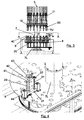
- Figures 1, 2 and 3 are a perspective, plan and profile view, respectively of the machine (1), object of the present invention.
- the rotary filling machine object of the present invention is of the variety comprising:
- each filling station (5) comprises:
- a lower portion of the filling station (5) is arranged on a lower portion of the carrousel (6), which in accordance with the present example, comprises:
- An upper portion of the filling station (5) is arranged on an upper portion of the carrousel (6), which in accordance with the present example, comprises:
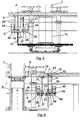
- FIGS 4 , 5 and 6 illustrate the rotation means (40) and vertical displacement means (60) of a filling station (5) in more detail.
- the rotation means (40) are configured to rotate the package (2) on the carrousel (6), comprising:
- the vertical bar (41) is arranged perpendicularly between the first disc (8) and the second disc (9), joined to the same via a first lower tread element (51) and a first upper tread element (52), respectively, whilst the rotation mechanism (44), comprises:
- the vertical displacement means (20) comprise:
- the elevator spindle (21) is arranged perpendicularly between the first disc (8) and the second disc (9), joined to the same via a second lower tread element (31) and a second upper tread element (32) respectively, whilst the vertical transfer cart (23) is joined to the vertical bar (41).
- the elevator mechanism (24) comprises:
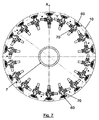
- Figure 7 shows how the filling stations (5) are arranged in relation to the carrousel (6), wherein the dosage means (60) and horizontal displacement means (70) can be observed.
- FIGs 8 and 9 are more detailed representations of the dosage means (60). As can be seen, they are configured to administer the dosage of a product (100), formed by a plurality of compositions (100A, 100B), which are supplied separately (see Figures 12A and 13A ).
- the dosage means (60) comprise:
- the dosage means (60) comprise a final flexible channel (65A, 65B) for each composition (100A, 100B), configured to facilitate the displacement of the filling head piece (62) on the horizontal plane (XY).
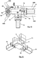
- Figures 10 and 11 represent the horizontal displacement (70) in greater detail. As can be seen, in accordance with the present example, they are based on the movement of the filling head piece (62) of the dosage means (60) on the horizontal plane (XY), the package (2) remaining fixed on said plane.
- the horizontal displacement means (70) comprise:
- the horizontal displacement means (70) comprise:
- the lateral transfer cart (72) is preferably joined to the carrousel (6) and to the front transfer cart (76), whilst said front transfer cart (76) is joined to the filling head piece (62).
- Figure 12A is a front schematic view of the generation of a first example of a filling pattern. Arrows have been used in this figure to indicate the direction of all of the movements involved in generating it.
- the filling pattern has a first composition (100A) with a helical form variable diameter, along the length of the package (2), absorbed in a second composition (100B).
- the relative vertical distance (dZ) between the package (2) and the output mouthpiece (63) in the direction of the vertical axis (Z) varies from the bottom of the package (2) to beyond its mouth, according to the level represented in said figure.
- Figure 12C is a lateral view of the result obtained using this first example of a filling pattern.
- Figure 13A is a front schematic view of the generation of a second example of a filling pattern (100). Arrows are contained therein in order to represent the direction of all the movements involved in generating it.
- the filling pattern has a first composition (100B), divided into at least two parts absorbed in a second composition (100A).
- the relative vertical distance (dZ) between the package (2) and the output mouthpiece (63) in the direction of the vertical axis (Z) varies from the bottom of the package (2) to beyond its mouth, according to the level shown in said figure.
- Figure 13C is a side view of the result obtained using this second example of a filling pattern.
Landscapes
- Engineering & Computer Science (AREA)
- Mechanical Engineering (AREA)
- Auxiliary Devices For And Details Of Packaging Control (AREA)
- Basic Packing Technique (AREA)
- Filling Of Jars Or Cans And Processes For Cleaning And Sealing Jars (AREA)
Description
- The present invention refers to a rotary filling machine, which offers a large number of benefits in the packaging of monophase and multiphase products, at the level of medium and high speed industrial production.
- The present invention has been especially designed to be applied to high and medium speed packaging lines in general, which is particularly suited to the packaging of cosmetic, alimentary, pharmaceutical or other home cleaning products, amongst others.
- The packaging industry is constantly developing in the pursuit of more efficient packaging processes, which are more environmentally friendly and offer a greater level of care and conservation as far as the products to be packaged are concerned. Over recent years, said development has tended decisively towards obtaining new forms of presentation, especially in the cosmetic sector, which combine both the external design of the package itself and the arrangement of the product contained therein, the latter aspect relating directly to filling technologies (machinery and processes).
- New forms of presentation bestow various benefits on the packaged products, at both aesthetic and operational level. Aesthetic benefits are particularly relevant, making said products more commercially attractive within an increasingly demanding and selective market. Operational benefits mainly relate to a suitable way of using the product, enabling the various compositions from which it is formed to be conveniently mixed, in order to achieve the optimal effect expected from the same.
- Meanwhile, packaging design and filling technologies have been developed in order to find these new forms of presentation. Nevertheless, even if said developments do not seem to present limits in terms of package design, existing filling technologies continue to present significant technical drawbacks.
- Therefore, pieces of apparatus which make it possible to fill a package with two or more compositions, which usually have distinct physical and chemical properties, in accordance with a product contained therein, which has a certain filling pattern, is known.
- The technology used to this effect constitutes inline fillers, in which all filling stations are aligned and parallel to the production line. These machines only facilitate low and medium speed production, with a maximum of 150 units being produced per minute. These machines operate in an indexing manner. In other words, the various operations or stages (loading packages, filling, unloading packages etc.,) involved are carried out intermittently according to a sequential order. In turn, this simplifies the number of mechanisms and controls, which is why, within the range of speeds within which work can be carried out, it is usually the most profitable option.
- Nevertheless, when it comes to filling packages at higher speeds or in other words, filling more than 150 units per minute, with two or more compositions, formed inside a filling pattern, the technical difficulty increases.
- In monophase products formed by one single composition and even for multiphase products formed by more than one composition, which do not generate filling patterns but are rather only mixed just before being introduced into the package, this technical jump is achieved using rotary filling machines, also known as "rotary fillers". These machines work continuously or in other words, the various operations or stages (loading packages, filling, unloading packages etc.,) carried out are done so on various packages simultaneously.
- The rotary filling machines, such as the one shown in document
US8386072B1 , consist of a filling carrousel, in which the various filling stations, with their corresponding dosage means, are located in the same diameter. Said carrousel rotates constantly. The packages are introduced from the production line to the filling carrousel, known as an "infeed starwheel". The packages are thus deposited on a base, which can be displaced in the direction of a vertical axis. Once the process has come to an end, the packages are extracted from the carrousel by means of an "outfeed starwheel". Both starwheels rotate in synchronisation with the filling carrousel and are tangent with the production line. - A machine formed in a production line in this way is capable of reaching very high speeds (1000 units per minute). The main advantage of it stems from the fact that the package always moves at a constant speed and the machine maintains a constant rotational movement, thus preventing the packages from stopping or being removed alongside the problems resulting in the event of demanding high speeds from inline fillers.
- Nevertheless, in contrast to inline fillers, the various operations are not carried out in an index-linked way but rather continuously. As a result, not all the packages are filled at the same time, but rather each one of the packages in the carrousel can be found at a different stage of the filling cycle, for example. The filling stations therefore operate independently. In other words, each one of them should be configured to carry out as many operations as necessary in order to fill each package. Therefore, bearing in mind that the filling stations which make it possible to generate filling patterns require a significant number of operations and have a considerable number of compositions linked to them, their use in rotary filling machines is somewhat complicated at a technical level and gives rise to extremely elevated costs.
- Mainly for this reason, the existence of rotary filling machines which facilitate rotational movement between the package and dosage means, around the vertical axis and at the same time the possibility of varying the relative distance between the package and the dosage means in a horizontal plane perpendicular to said vertical axis, is not recognised for the filling of packages with two or more compositions, which form a complex filling pattern therein.
- The rotary filling machine, object of the present invention, resolves the problems set out above, via a formation which amplifies the relative movements between the package and the dosage means, thus achieving medium and high speed levels of industrial production and a greater number of benefits in the packaging of monophase and multiphase products. It may, for example, improve the distribution of a monophase product, exerting a centrifugal force on the same or create a countless number of filling patterns for a multiphase product in a package.
- The rotary filling machine, object of the present invention, is of the variety comprising:
- a rotating infeed starwheel, configured to supply packages;
- a rotating filling carousel, upon which a plurality of filling stations are arranged diametrically to the same, each one of them being configured to receive a package coming from the infeed starwheel, wherein each filling station comprises:
- dosage means configured to administer the dosage of a product inside the package;
- vertical displacement means, configured to vary the relative distance between the package and the dosage means, in the direction of a vertical axis and;
- rotation means, configured to provide a relative rotation movement between the package and the dosage means, around the vertical axis, wherein the rotation means are configured to rotate the package in relation to the carrousel; and
- a rotating outfeed starwheel configured to remove the packages from the filling carousel, wherein both infeed and outfeed starwheels are configured to rotate in synchronisation with the filling carrousel.
- In addition, each filling station comprises:
- horizontal displacement means, configured to vary the relative distance between the package and the dosage means on a horizontal plane, which is perpendicular to the vertical axis.
- Of the wide range of possibilities available for constructing the carrousel, the carrousel preferably comprises:
- a central rotating column and;
- a first and second disc which are concentric to the central column and joined to the same, arranged in such a way that they are parallel in a lower portion of said column.
- The dosage means are preferably configured to administer the dosages of a product, formed by a plurality of compositions, which are supplied separately, it being possible to have two, three, four or more compositions. In accordance with a preferred embodiment, said dosage means comprise:
- a measuring unit for each composition, configured to regulate the flow of the same;
- a filling head piece, which has an output mouthpiece, configured to administer the dosage of each composition and orientated towards the mouth of the package and;
- a distribution channel for each composition, configured to distribute the flow to the measuring unit.
- The measuring units are charged with measuring the amount of each composition to be filled at each instant or moment of the process. Those which use dosage cylinders or other positive displacement dosage pumps (peristaltic pumps, gear pumps etc.,) are amongst the most common, in addition to those which use flow meters. The first kind measure the flow by calculating the volume displaced by said positive displacement pumps, for example, the displacement of a piston within a dosage cylinder is known, as well as the volume displaced by the same. In these cases, the pump regulation is carried out by regulating the speed of the corresponding positive displacement pump. The second type use flow meters to measure the flow, whilst they are regulated by means of proportional valves. In order to increase the pressure, closed-loop controls are usually applied between the flow meter and the aperture or close of the proportional valve.
- The dosage means preferably comprise a final flexible channel for each composition, configured to facilitate the displacement of the filling head piece on the horizontal plane.
- The rotation means are configured to rotate the package on the carrousel, comprising:
- a vertical bar joined to the carrousel, coaxial to the vertical axis and with freedom of axial rotation;
- a rotation base arranged on an upper end of the vertical bar, configured to receive a package coming from the infeed starwheel and;
- a rotation mechanism configured to rotate the vertical bar.
- In accordance with one particular embodiment, the vertical bar is arranged perpendicularly between the first disc and second disc, joined to the same via a first lower tread element and a first upper tread element respectively, whilst the rotation mechanism comprises:
- a rotation drive, which is joined to the first disc;
- a first motor wheel driven by the rotation drive and;
- a first driven wheel, concentric to the vertical bar and joined to the same, which engages with the first motor wheel through a first transmission belt, wherein the first motor wheel and the first driven wheel are arranged below said first disc.
- The vertical displacement means preferably comprise:
- an elevator spindle, joined to the carrousel, parallel to the vertical axis and with freedom of axial rotation;
- a vertical transfer cart, crossed by the elevator spindle and which may be displaced along the length of the same, the displacement of which is transmitted to the package and;
- an elevator mechanism, configured to rotate the elevator spindle and give rise to the controlled displacement of the vertical transfer cart along the length of said elevator spindle.
- In accordance with a particular embodiment, the elevator spindle is arranged perpendicularly between the first disc and second disc, joined to the same via a second lower tread element and a second upper tread element, respectively, whilst the vertical transfer cart is joined to the vertical bar.
- In turn, the elevator mechanism comprises:
- an elevator drive, which is joined to the first disc;
- a second motor wheel, driven by the elevator drive;
- a second driven wheel, concentric to the elevator spindle and joined to the same, which engages with the second motor wheel via a second transmission belt, wherein the second motor wheel and the second driven wheel are arranged below said first disc and;
- a guide bar located perpendicularly between the first disc and second disc, joined to the same and crossed by the vertical transfer cart, in order to guide the displacement of the same.
- The horizontal displacement means are preferably based on the movement of the filling head piece of the dosage means on the horizontal plane, the package remaining fixed on said plane. In this sense, the horizontal displacement means comprise:
- a lateral spindle parallel to the Y axis of the horizontal plane;
- a lateral transfer cart, crossed by the lateral spindle and which may be displaced along the length of the same, the displacement of which is transmitted to the filling head piece of the dosage means and;
- a lateral displacement mechanism, configured to rotate the lateral spindle and give rise to the controlled displacement of the lateral transfer cart along the length of said lateral spindle.
- In turn, the horizontal displacement means comprise:
- a front spindle parallel to the X axis of the horizontal plane;
- a front transfer cart, crossed by the lateral spindle and which may be displaced along the length of the same, the displacement of which is transmitted to the filling head piece of the dosage means and;
- a front displacement mechanism, configured to rotate the front spindle and give rise to the controlled displacement of the front transfer cart along the length of said front spindle.
- Of the various possible fixation options for the horizontal displacement means, the lateral transfer cart is preferably joined to the carrousel and to the front transfer cart, whilst said front transfer cart is joined to the filling head piece.
- In accordance with other design possibilities, the horizontal displacement means are based on the movement of the package on the horizontal plane, the dosage means remaining fixed.
- Both the rotation of the package and the variation of the relative vertical and horizontal distances between the package and the dosage means are carried out in a controlled way, the angle of rotation of the package and the relative vertical and horizontal distances between the same and the mouthpiece being known at all times. For this reason, rotation, vertical displacement and horizontal displacement mechanisms are preferably employed, formed by servomotors that can be controlled in terms of both speed and position.
- The control means of the machine, object of the present invention, comprise all automatisms, visualisation devices and devices for introducing operational information, process hardware and software necessary for correct operation and functioning of the method and apparatus of the present invention.
- The machine, object of the present invention, makes it possible to perform various movements, namely rotating the package, vertical displacement (Z) and horizontal displacement (X and Y), either simultaneously or alternately. That is to say, depending on the complexity of the filling pattern, any of the following groups of movements may be required in order to obtain it:
- a) Rotation + Horizontal displacement (X or Y);
- b) Rotation + Horizontal displacement X + Horizontal displacement Y;
- c) Vertical displacement Z + Horizontal displacement (X or Y);
- d) Vertical displacement Z + Horizontal displacement X + Horizontal displacement Y;
- e) Rotation + Vertical displacement Z+ Horizontal displacement (X or Y) and;
- f) Rotation + Vertical displacement Z + Horizontal displacement X + Horizontal displacement Y.
- Below is a brief description of a series of drawings which facilitate a better understanding of the invention, relating specifically to a preferred embodiment of said invention and providing a non-limiting example thereof.
-
Figure 1 is a perspective view of the machine, object of the present invention. -
Figure 2 is a plan view ofFigure 1 . -
Figure 3 is a profile view ofFigure 1 . -
Figure 4 is a perspective view of the rotation means and vertical displacement of a filling station. -
Figure 5 is a profile view of the rotation means of a filling station. -
Figure 6 is a longitudinal cross-section of the rotation means of a filling station. -
Figure 7 is a sectioned view ofFigure 3 , according to the cut line A-A. -
Figure 8 is a front view of a filling station. -
Figure 9 is a profile view of a filling station. -
Figure 10 is a sectioned view ofFigure 9 , according to the cut line B-B. -
Figure 11 is a perspective view of a detail of the horizontal displacement means. -
Figure 12A is a front schematic view of the generation of a first example of a filling pattern. -
Figure 12B is a sectioned view ofFigure 12A , according to the cut line C-C. -
Figure 12C is a side view of a package, which shows the result of applying the first example of a filling pattern. -
Figure 13A is a front schematic view of the generation of a second example of a filling pattern. -
Figure 13B is a sectioned view ofFigure 13A , according to the cut-line D-D. -
Figure 13C is a side view of a package which shows the result of applying the second example of a filling pattern. -
Figures 1, 2 and3 are a perspective, plan and profile view, respectively of the machine (1), object of the present invention. As can be seen, the rotary filling machine object of the present invention, is of the variety comprising: - a rotating infeed starwhell (3), configured to supply packages (2);
- a rotating filling carrousel (6), upon which a plurality of filling stations (5) are located diametrically to the same, each one of which is configured to receive a package (2) coming from the infeed starwheel (3), wherein each filling station (5) comprises:
- dosage means (60) configured to administer the dosage of a product (100) inside the package (2) (see
figures 12C and13C ); - vertical displacement means (20) configured to vary the relative distance between the package (2) and the dosage means (60) in the direction of a vertical axis (Z) and;
- rotation means (40), configured to provide a relative rotation movement (R) between the package (2) and the dosage means (60), around the vertical axis (Z), wherein the rotation means (40) are configured to rotate the package (2) in relation to the carrousel (6); and
- dosage means (60) configured to administer the dosage of a product (100) inside the package (2) (see
- a rotating outfeed starwheel (4) configured to remove the packages (2) from the filling carrousel (6), wherein both infeed (3) and outfeed (4) starwheels are configured to rotate in synchronisation with the filling carrousel (6).
- In addition, each filling station (5) comprises:
- horizontal displacement means (70) (see
Figures 7 to 11 ) configured to vary the relative distance between the package (2) and the dosage means (60) on a horizontal plane (XY) perpendicular to the vertical axis (Z). - A lower portion of the filling station (5) is arranged on a lower portion of the carrousel (6), which in accordance with the present example, comprises:
- a central rotating column (7) and;
- a first (8) and second disk (9), concentric to the central column (7) and joined to the same, arranged in such a way that they are parallel in a lower portion (7L) of said column (7).
- An upper portion of the filling station (5) is arranged on an upper portion of the carrousel (6), which in accordance with the present example, comprises:
- a third (10) and fourth (11) disc concentric to the central column (7) and joined to the same, arranged in such a way that they are parallel in an upper portion (7U) of said column (7).
-
Figures 4 ,5 and 6 illustrate the rotation means (40) and vertical displacement means (60) of a filling station (5) in more detail. As can be seen, the rotation means (40) are configured to rotate the package (2) on the carrousel (6), comprising: - a vertical bar (41) joined to the carrousel (6), coaxial to the vertical axis (Z) with freedom of axial movement;
- a rotation base (43) arranged on an upper end (42) of the vertical bar (41), configured to receive a package (2) coming from the infeed starwheel (3) and;
- a rotation mechanism (44), configured to rotate the vertical bar (41).
- The vertical bar (41) is arranged perpendicularly between the first disc (8) and the second disc (9), joined to the same via a first lower tread element (51) and a first upper tread element (52), respectively, whilst the rotation mechanism (44), comprises:
- a rotation drive (45), which is joined to the first disc (8);
- a first motor wheel (46) driven by the rotation drive (45) and;
- a first driven wheel (47), concentric to the vertical bar (41) and joined to the same, which engages with the first motor wheel (46) via a first transmission belt (48), wherein the first motor wheel (46) and the first driven wheel (47) are arranged below said first disc (8).
- In turn, the vertical displacement means (20) comprise:
- an elevator spindle (21) joined to the carrousel (6), parallel to the vertical axis (Z) and with freedom of axial rotation;
- a vertical transfer cart (23), crossed by the elevator spindle (21) and which may be displaced along the length of the same, the displacement of which is transmitted to the package (2) and;
- an elevator mechanism (24) configured to rotate the elevator spindle (21) and give rise to the controlled displacement of the vertical transfer cart (23) along the length of said elevator spindle (21).
- The elevator spindle (21) is arranged perpendicularly between the first disc (8) and the second disc (9), joined to the same via a second lower tread element (31) and a second upper tread element (32) respectively, whilst the vertical transfer cart (23) is joined to the vertical bar (41).
- In turn, the elevator mechanism (24) comprises:
- an elevator drive (25), which is joined to the first disc (8);
- a second motor wheel (26) driven by the elevator drive (25);
- a second driven wheel (27), concentric to the elevator spindle (21) and joined to the same, which engages with the second motor wheel (26) via a second transmission belt (28), wherein the second motor wheel (26) and the second driven wheel (27) are arranged below said first disc (8) and;
- a guide bar (29) which is arranged perpendicularly between the first disc (8) and the second disc (9) in such a way that it is joined to the same, crossed by the vertical transfer cart (23), in order to guide the displacement of the same.
-
Figure 7 shows how the filling stations (5) are arranged in relation to the carrousel (6), wherein the dosage means (60) and horizontal displacement means (70) can be observed. -
Figures 8 and 9 are more detailed representations of the dosage means (60). As can be seen, they are configured to administer the dosage of a product (100), formed by a plurality of compositions (100A, 100B), which are supplied separately (seeFigures 12A and13A ). The dosage means (60) comprise: - a measuring unit (61A, 61B) for each composition (100A, 100B), configured to regulate the flow of the same;
- a filling head piece (62) which has an output mouthpiece (63), configured to administer the dosage of each composition (100A, 100B), which is orientated towards the mouth of the package (2) and;
- a distribution channel (64A, 64B) for each composition (100A, 100B), configured to distribute the flow to the measuring unit (61A, 61B).
- In turn, the dosage means (60) comprise a final flexible channel (65A, 65B) for each composition (100A, 100B), configured to facilitate the displacement of the filling head piece (62) on the horizontal plane (XY).
-
Figures 10 and 11 represent the horizontal displacement (70) in greater detail. As can be seen, in accordance with the present example, they are based on the movement of the filling head piece (62) of the dosage means (60) on the horizontal plane (XY), the package (2) remaining fixed on said plane. In this sense, the horizontal displacement means (70) comprise: - a lateral spindle (71), parallel to the Y axis of the horizontal plane (XY);
- a lateral transfer cart (72), crossed by the lateral spindle (71), which may be displaced along the length of the same, the displacement of which is transmitted to the filling head piece (62) of the dosage means (60) and;
- a lateral displacement mechanism (73), configured to rotate the lateral spindle (71) and give rise to the controlled displacement of the lateral transfer cart (72) along the length of said lateral spindle (71).
- In turn, the horizontal displacement means (70) comprise:
- a front spindle (75) parallel to the X axis of the horizontal plane (XY);
- a front transfer cart (76) crossed by the lateral spindle (75), which may be displaced along the length of the same, the displacement of which is transmitted to the filling head piece (62) of the dosage means (60) and;
- a front displacement mechanism (77), configured to rotate the front spindle (75) and give rise to the controlled displacement of the front transfer cart (76) along the length of said front spindle (75).
- Of the various possible fixation options for the horizontal displacement means (70), the lateral transfer cart (72) is preferably joined to the carrousel (6) and to the front transfer cart (76), whilst said front transfer cart (76) is joined to the filling head piece (62).
-
Figure 12A is a front schematic view of the generation of a first example of a filling pattern. Arrows have been used in this figure to indicate the direction of all of the movements involved in generating it. According to this first example, the filling pattern has a first composition (100A) with a helical form variable diameter, along the length of the package (2), absorbed in a second composition (100B). - The relative vertical distance (dZ) between the package (2) and the output mouthpiece (63) in the direction of the vertical axis (Z) varies from the bottom of the package (2) to beyond its mouth, according to the level represented in said figure.
- In
Figure 12B , it is possible to observe that the relative horizontal distance (dX, dY) between the package (2) and the output mouthpiece (63) varies from the internal contour of the package (2) to the external contour of the mouthpiece (63). In the mouthpiece (63) section, it is possible to observe the openings through which the dosage of each composition (100A, 100B) is administered. -
Figure 12C is a lateral view of the result obtained using this first example of a filling pattern. -
Figure 13A is a front schematic view of the generation of a second example of a filling pattern (100). Arrows are contained therein in order to represent the direction of all the movements involved in generating it. According to this second example, the filling pattern has a first composition (100B), divided into at least two parts absorbed in a second composition (100A). - The relative vertical distance (dZ) between the package (2) and the output mouthpiece (63) in the direction of the vertical axis (Z) varies from the bottom of the package (2) to beyond its mouth, according to the level shown in said figure.
- In
Figure 13B , it is possible to observe that the relative horizontal distance (dX, dY) between the package (2) and the output mouthpiece (63) varies from the internal contour of the package (2) to the external contour of the mouthpiece (63). In the mouthpiece (63) section, it is possible to observe the openings through which the dosage of each composition (100A, 100B) is administered. The dosage of the first composition (100A) is administered through the two lateral openings. -
Figure 13C is a side view of the result obtained using this second example of a filling pattern.
Claims (12)
- Rotary filling machine, comprising:• a rotating infeed starwheel (3) configured to supply packages (2);• a rotating filling carrousel (6) upon which a plurality of filling stations (5) are arranged diametrically to the same, each one of which is configured to receive a package (2) coming from the infeed starwheel (3), wherein each filling station (5) comprises:• dosage means (60), configured to administer the dosage of a product (100) inside the package (2);• vertical displacement means (20) configured to vary the relative distance between the package (2) and the dosage means (60) in the direction of a vertical axis (Z) and;• rotation means (40), configured to provide a relative rotation movement (R) between the package (2) and the dosage means (60), around the vertical axis (Z), wherein the rotation means (40) are configured to rotate the package (2) in relation to the carrousel (6); and• a rotating outfeed starwheel (4), configured to remove the packages (2) from the filling carrousel (6), wherein both infeed (3) and outfeed (4) starwheels are configured to rotate in synchronisation with the filling carrousel (6); said machine (1) being characterised in that each filling station (5) comprises:• horizontal displacement means (70), configured to vary the relative distance between the package (2) and the dosage means (60) on a horizontal plane (XY) perpendicular to the vertical axis (Z);and in that the rotation means (40) comprise:• a vertical bar (41) joined to the carrousel (6), which is coaxial to the vertical axis (Z) and has freedom of axial rotation;• a rotation base (43) arranged on an upper end (42) of the vertical bar (41), configured to receive a package (2) coming from the infeed starwheel (3) and;• a rotation mechanism (44), configured to rotate the vertical bar (41).
- Rotary filling machine according to claim 1, characterised in that the carrousel (6) comprises:• a central rotating column (7) and;• a first (8) and second (9) disc, concentric to the central column (7) and joined to the same, arranged in such a way that they are parallel in a lower portion (7L) of said column (7).
- Rotary filling machine according to any of the claims 1 to 2, characterised in that the dosage means (60) are configured to administer the dosage of a product (100) formed by a plurality of compositions (100A, 100B) which are supplied separately.
- Rotary filling machine according to claim 3, characterised in that the dosage means (60) comprise:• a measuring unit (61A, 61B) for each composition (100A, 100B), configured to regulate the flow of the same;• a filling head piece (62), which has an output mouthpiece (63), configured to administer the dosage of each composition (100A, 100B) and which is orientated towards the mouth of the package (2) and;• a distribution channel (64A, 64B) for each composition (100A, 100B), configured to distribute the flow to the measuring unit (61A, 61B).
- Rotary filling machine according to claim 4, characterised in that the dosage means (60) comprise a final flexible channel (65A, 65B) for each composition (100A, 100B), configured to facilitate the displacement of the filling head piece (62) on the horizontal plane (XY).
- Rotary filling machine according to claim 2, characterised in that the vertical bar (41) is arranged perpendicularly between the first disc (8) and the second disc (9), joined to the same via a first lower tread element (51) and a first upper tread element (52), respectively and also characterised in that the rotation mechanism (44) comprises:• a rotation drive (45) which is joined to the first disc (8);• a first motor wheel (46) driven by the rotation drive (45) and;• a first driven wheel (47) concentric to the vertical bar (41) and joined to the same, which engages with the first motor wheel (46) via a first transmission belt (48), wherein the first motor wheel (46) and the first driven wheel (47) are arranged below said first disc (8).
- Rotary filling device according to any of the claims 1 to 6 characterised in that the vertical displacement means (20) comprise:• an elevator spindle (21) joined to the carrousel (6), which is parallel to the vertical axis (Z) and has freedom of axial rotation;• a vertical transfer cart (23), crossed by the elevator spindle (21), which can be displaced along the length of the same, the displacement of which is transmitted to the package (2) and;• an elevation mechanism (24) configured to rotate the elevator spindle (21) and give rise to the controlled displacement of the vertical transfer cart (23) along the length of said elevator spindle (21).
- Rotary filling machine according to claims 2 and 7, characterised in that the elevator spindle (21) is arranged perpendicularly between the first disc (8) and the second disc (9), joined to the same via a second lower tread element (31) and a second upper tread element (32) respectively and characterised in that the vertical transfer cart (23) is joined to the vertical bar (41).
- Rotary filling machine according to claim 8, characterised in that the elevator mechanism (24) comprises:• an elevator drive (25), which is joined to the first disc (8);• a second motor wheel (26), driven by the elevator drive (25);• a second driven wheel (27), concentric to the elevator spindle (21) and joined to the same, which engages with the first motor wheel (26), via a second transmission belt (28), wherein the second motor wheel (26) and the second driven wheel (27) are arranged below said first disc (8) and;• a guide bar (29), which is arranged perpendicularly between the first disc (8) and the second disk (9), in such a way that it is joined to the same, crossed by the vertical transfer cart (23), in order to guide the displacement of the same.
- Rotary filling machine according to any of the claims 4 to 5 characterised in that the horizontal displacement means (70) comprise:• a lateral spindle (71) parallel to the Y axis of the horizontal plane (XY);• a lateral transfer cart (72), crossed by the lateral spindle (71), which may be displaced along the length of the same and the displacement of which is transferred to the filling head piece (62) of the dosage means (60) and;• a lateral displacement mechanism (73), configured to rotate the lateral spindle (71) and give rise to the controlled displacement of the lateral transfer cart (72) along the length of said lateral spindle (71).
- Rotary filling machine according to claim 10, characterised in that the horizontal displacement means (70) comprise:• a front spindle (75) parallel to the X axis of the horizontal plane (XY);• a front transfer cart (76), crossed by the lateral spindle (75) which may be displaced along the length of the same, the displacement of which is transferred to the filling head piece (62) of the dosage means (60) and;• a front displacement mechanism (77), configured to rotate the front spindle (75) and give rise to the controlled displacement of the front transfer cart (76) along the length of said front spindle (75).
- Rotary filling machine according to claim 11, characterised in that the lateral transfer cart (72) is joined to the carrousel (6) and to the front transfer cart (76) and characterised in that said front transfer cart (76) is joined to the filling head piece (62).
Priority Applications (6)
| Application Number | Priority Date | Filing Date | Title |
|---|---|---|---|
| EP13382300.5A EP2829477B1 (en) | 2013-07-24 | 2013-07-24 | Rotary filling machine |
| PL13382300.5T PL2829477T3 (en) | 2013-07-24 | 2013-07-24 | Rotary filling machine |
| DK13382300.5T DK2829477T3 (en) | 2013-07-24 | 2013-07-24 | Rotary Filling machine |
| ES13382300.5T ES2583013T3 (en) | 2013-07-24 | 2013-07-24 | Rotary filling machine |
| CA2857137A CA2857137A1 (en) | 2013-07-24 | 2014-07-18 | Rotary filling machine |
| US14/339,973 US9567123B2 (en) | 2013-07-24 | 2014-07-24 | Rotary filling machine |
Applications Claiming Priority (1)
| Application Number | Priority Date | Filing Date | Title |
|---|---|---|---|
| EP13382300.5A EP2829477B1 (en) | 2013-07-24 | 2013-07-24 | Rotary filling machine |
Publications (2)
| Publication Number | Publication Date |
|---|---|
| EP2829477A1 EP2829477A1 (en) | 2015-01-28 |
| EP2829477B1 true EP2829477B1 (en) | 2016-04-27 |
Family
ID=49486422
Family Applications (1)
| Application Number | Title | Priority Date | Filing Date |
|---|---|---|---|
| EP13382300.5A Active EP2829477B1 (en) | 2013-07-24 | 2013-07-24 | Rotary filling machine |
Country Status (6)
| Country | Link |
|---|---|
| US (1) | US9567123B2 (en) |
| EP (1) | EP2829477B1 (en) |
| CA (1) | CA2857137A1 (en) |
| DK (1) | DK2829477T3 (en) |
| ES (1) | ES2583013T3 (en) |
| PL (1) | PL2829477T3 (en) |
Families Citing this family (9)
| Publication number | Priority date | Publication date | Assignee | Title |
|---|---|---|---|---|
| US10524980B2 (en) * | 2016-09-13 | 2020-01-07 | Vanrx Pharmasystems, Inc. | Apparatus and method for aseptically filling pharmaceutical containers with a pharmaceutical fluid using rotary stage |
| ES2879295T3 (en) * | 2017-04-28 | 2021-11-22 | Volpak Sau | An automatic packaging machine to fill a bag made of a heat sealable material with a dose of a loose product |
| US10919750B2 (en) | 2017-06-06 | 2021-02-16 | Pacific Packaging Machinery, Llc | Rotary filling machine |
| IT202000018850A1 (en) * | 2020-07-31 | 2022-01-31 | Gd Spa | UNIT AND METHOD OF HANDLING AND FILLING A CONTAINER AND PRODUCTION APPARATUS FOR RELATED ITEMS |
| CN112607074B (en) * | 2020-12-15 | 2023-04-28 | 安徽中一智能科技有限公司 | Automatic quantitative output mechanism for liquid materials of high-speed packaging machine |
| CN114348353B (en) * | 2021-12-06 | 2024-03-01 | 湖南浩森胶业有限公司 | Quick adhesive packaging welding system |
| CN117775362A (en) * | 2022-12-02 | 2024-03-29 | 周淑叶 | A sampling test tube filling device |
| CN117775363B (en) * | 2024-01-30 | 2026-03-27 | 中博瑞康(上海)生物技术有限公司 | A method for dispensing cell fluid |
| CN117885960B (en) * | 2024-01-24 | 2025-12-26 | 楚天科技股份有限公司 | A powder filling mechanism |
Family Cites Families (12)
| Publication number | Priority date | Publication date | Assignee | Title |
|---|---|---|---|---|
| US3892264A (en) * | 1973-10-10 | 1975-07-01 | Federal Manufacturing Company | Method and apparatus for filling bottles |
| US4159028A (en) * | 1977-03-28 | 1979-06-26 | Almay, Inc. | Method of forming and containerizing a multiphase cosmetic composition |
| US4966205A (en) * | 1988-02-02 | 1990-10-30 | Pola Chemical Industries Ltd. | Method and apparatus for charging transparent material |
| DE59800608D1 (en) * | 1997-08-18 | 2001-05-17 | Benhil Gasti Verpackungsmaschi | Device and method for the metered filling of liquid to pasty products |
| US6065508A (en) * | 1998-11-06 | 2000-05-23 | Pneumatic Scale Corporation | Filler product supply apparatus and method |
| US6516838B2 (en) * | 1999-07-28 | 2003-02-11 | Patrick Thibiant | Apparatus and process for forming novel spiral compositions |
| ATE294739T1 (en) * | 2002-09-26 | 2005-05-15 | Tecniche Costec S R L Costruzi | ROTARY TABLE FILLING MACHINE |
| CN1780601B (en) * | 2003-05-01 | 2010-05-12 | 宝洁公司 | Visually distinct multi-liquid compositions |
| DE102006033511A1 (en) * | 2006-07-20 | 2008-01-24 | Khs Ag | treatment machine |
| WO2010101576A1 (en) * | 2009-03-06 | 2010-09-10 | Colgate-Palmolive Company | Apparatus and method for filling a container with at least two components of a composition |
| US8386072B1 (en) * | 2009-04-20 | 2013-02-26 | Pneumatic Scale Corporation | Dual meter filler apparatus and method |
| DK2639163T3 (en) * | 2012-03-15 | 2014-12-08 | Antonio Mengibar S A | Method and apparatus for generating a filling pattern for filling containers |
-
2013
- 2013-07-24 EP EP13382300.5A patent/EP2829477B1/en active Active
- 2013-07-24 PL PL13382300.5T patent/PL2829477T3/en unknown
- 2013-07-24 DK DK13382300.5T patent/DK2829477T3/en active
- 2013-07-24 ES ES13382300.5T patent/ES2583013T3/en active Active
-
2014
- 2014-07-18 CA CA2857137A patent/CA2857137A1/en not_active Abandoned
- 2014-07-24 US US14/339,973 patent/US9567123B2/en active Active
Also Published As
| Publication number | Publication date |
|---|---|
| US9567123B2 (en) | 2017-02-14 |
| DK2829477T3 (en) | 2016-08-15 |
| CA2857137A1 (en) | 2015-01-24 |
| EP2829477A1 (en) | 2015-01-28 |
| ES2583013T3 (en) | 2016-09-16 |
| US20150027585A1 (en) | 2015-01-29 |
| PL2829477T3 (en) | 2016-10-31 |
Similar Documents
| Publication | Publication Date | Title |
|---|---|---|
| EP2829477B1 (en) | Rotary filling machine | |
| CA2808954C (en) | Method and apparatus for generating a filling pattern for filling containers | |
| RU2474531C2 (en) | System of multi-jet filling of containers | |
| DE60336462D1 (en) | Filling machine for capsules | |
| CN104276537B (en) | High-speed canning spiral cover system | |
| DE602009000746D1 (en) | Apparatus for preparing and distributing infusion products, in particular coffee, in variable volumetric quantities | |
| CN103754411A (en) | Full-automatic paper box opening, paper box casing and adhesive tape sealing integrated machine | |
| RU2706626C2 (en) | Method for manufacturing filled and closed container, device for implementing method and container made by said method | |
| EP3386903B1 (en) | Bottling machine comprising at least two micro-carousels for additive fluids, and related method | |
| CN103342327A (en) | Weighing and filling production line of particle hot and spicy sauce | |
| CN202807126U (en) | Section type material continuous high-speed boxing machine | |
| CN202704022U (en) | Ampoule bottle automatic lettering and loading device | |
| CN203698739U (en) | Full-automatic carton unpacking and tape sealing all-in-one machine | |
| CN106697397B (en) | Directional-rotation send an edition device | |
| CN106586110A (en) | Bottle rotating mechanism and damage-free bottle feeding device adopting same | |
| CN104309825A (en) | Granular capsule packaging machine | |
| CN202848049U (en) | Quantitative medicine packaging device | |
| CN206151877U (en) | Double acting type capsule charge device | |
| CN203486192U (en) | Double-position encasing tidying machine with various specifications and easy replacement | |
| ITMN20080015A1 (en) | FILLING DEVICE FOR CONTAINERS THROUGH A PRODUCT CONTAINING A MAIN COMPONENT AND AT LEAST ONE VARIABLE ADDITIVE COMPONENT. | |
| CN105857790A (en) | Variable-speed bottle feeding/discharging transmission mechanism of powder filling machine | |
| CN204623874U (en) | Magnetic clutch controls formula screw metering system | |
| CN202080458U (en) | Workpiece conveying mechanism for injector swing machine | |
| CN103448945B (en) | Many specifications easily change dibit vanning arranging machine | |
| CN105292529A (en) | Medicine packaging machine |
Legal Events
| Date | Code | Title | Description |
|---|---|---|---|
| 17P | Request for examination filed |
Effective date: 20130724 |
|
| AK | Designated contracting states |
Kind code of ref document: A1 Designated state(s): AL AT BE BG CH CY CZ DE DK EE ES FI FR GB GR HR HU IE IS IT LI LT LU LV MC MK MT NL NO PL PT RO RS SE SI SK SM TR |
|
| AX | Request for extension of the european patent |
Extension state: BA ME |
|
| PUAI | Public reference made under article 153(3) epc to a published international application that has entered the european phase |
Free format text: ORIGINAL CODE: 0009012 |
|
| R17P | Request for examination filed (corrected) |
Effective date: 20150622 |
|
| RBV | Designated contracting states (corrected) |
Designated state(s): AL AT BE BG CH CY CZ DE DK EE ES FI FR GB GR HR HU IE IS IT LI LT LU LV MC MK MT NL NO PL PT RO RS SE SI SK SM TR |
|
| REG | Reference to a national code |
Ref country code: DE Ref legal event code: R079 Ref document number: 602013006980 Country of ref document: DE Free format text: PREVIOUS MAIN CLASS: B65B0003040000 Ipc: B65B0003120000 |
|
| GRAP | Despatch of communication of intention to grant a patent |
Free format text: ORIGINAL CODE: EPIDOSNIGR1 |
|
| RIC1 | Information provided on ipc code assigned before grant |
Ipc: B65B 3/12 20060101AFI20151021BHEP Ipc: B65B 43/60 20060101ALI20151021BHEP Ipc: B65B 43/50 20060101ALI20151021BHEP Ipc: B65B 39/00 20060101ALN20151021BHEP Ipc: B65B 3/30 20060101ALN20151021BHEP |
|
| RIC1 | Information provided on ipc code assigned before grant |
Ipc: B65B 39/00 20060101ALN20151112BHEP Ipc: B65B 43/50 20060101ALI20151112BHEP Ipc: B65B 3/12 20060101AFI20151112BHEP Ipc: B65B 43/60 20060101ALI20151112BHEP Ipc: B65B 3/30 20060101ALN20151112BHEP |
|
| INTG | Intention to grant announced |
Effective date: 20151126 |
|
| GRAS | Grant fee paid |
Free format text: ORIGINAL CODE: EPIDOSNIGR3 |
|
| GRAA | (expected) grant |
Free format text: ORIGINAL CODE: 0009210 |
|
| AK | Designated contracting states |
Kind code of ref document: B1 Designated state(s): AL AT BE BG CH CY CZ DE DK EE ES FI FR GB GR HR HU IE IS IT LI LT LU LV MC MK MT NL NO PL PT RO RS SE SI SK SM TR |
|
| REG | Reference to a national code |
Ref country code: GB Ref legal event code: FG4D |
|
| REG | Reference to a national code |
Ref country code: CH Ref legal event code: EP |
|
| REG | Reference to a national code |
Ref country code: AT Ref legal event code: REF Ref document number: 794487 Country of ref document: AT Kind code of ref document: T Effective date: 20160515 |
|
| REG | Reference to a national code |
Ref country code: IE Ref legal event code: FG4D |
|
| REG | Reference to a national code |
Ref country code: FR Ref legal event code: PLFP Year of fee payment: 4 |
|
| REG | Reference to a national code |
Ref country code: DE Ref legal event code: R096 Ref document number: 602013006980 Country of ref document: DE |
|
| REG | Reference to a national code |
Ref country code: NL Ref legal event code: FP |
|
| REG | Reference to a national code |
Ref country code: DK Ref legal event code: T3 Effective date: 20160812 |
|
| REG | Reference to a national code |
Ref country code: LT Ref legal event code: MG4D |
|
| REG | Reference to a national code |
Ref country code: AT Ref legal event code: MK05 Ref document number: 794487 Country of ref document: AT Kind code of ref document: T Effective date: 20160427 |
|
| REG | Reference to a national code |
Ref country code: ES Ref legal event code: FG2A Ref document number: 2583013 Country of ref document: ES Kind code of ref document: T3 Effective date: 20160916 |
|
| PG25 | Lapsed in a contracting state [announced via postgrant information from national office to epo] |
Ref country code: FI Free format text: LAPSE BECAUSE OF FAILURE TO SUBMIT A TRANSLATION OF THE DESCRIPTION OR TO PAY THE FEE WITHIN THE PRESCRIBED TIME-LIMIT Effective date: 20160427 Ref country code: LT Free format text: LAPSE BECAUSE OF FAILURE TO SUBMIT A TRANSLATION OF THE DESCRIPTION OR TO PAY THE FEE WITHIN THE PRESCRIBED TIME-LIMIT Effective date: 20160427 Ref country code: NO Free format text: LAPSE BECAUSE OF FAILURE TO SUBMIT A TRANSLATION OF THE DESCRIPTION OR TO PAY THE FEE WITHIN THE PRESCRIBED TIME-LIMIT Effective date: 20160727 |
|
| PG25 | Lapsed in a contracting state [announced via postgrant information from national office to epo] |
Ref country code: LV Free format text: LAPSE BECAUSE OF FAILURE TO SUBMIT A TRANSLATION OF THE DESCRIPTION OR TO PAY THE FEE WITHIN THE PRESCRIBED TIME-LIMIT Effective date: 20160427 Ref country code: HR Free format text: LAPSE BECAUSE OF FAILURE TO SUBMIT A TRANSLATION OF THE DESCRIPTION OR TO PAY THE FEE WITHIN THE PRESCRIBED TIME-LIMIT Effective date: 20160427 Ref country code: PT Free format text: LAPSE BECAUSE OF FAILURE TO SUBMIT A TRANSLATION OF THE DESCRIPTION OR TO PAY THE FEE WITHIN THE PRESCRIBED TIME-LIMIT Effective date: 20160829 Ref country code: GR Free format text: LAPSE BECAUSE OF FAILURE TO SUBMIT A TRANSLATION OF THE DESCRIPTION OR TO PAY THE FEE WITHIN THE PRESCRIBED TIME-LIMIT Effective date: 20160728 Ref country code: RS Free format text: LAPSE BECAUSE OF FAILURE TO SUBMIT A TRANSLATION OF THE DESCRIPTION OR TO PAY THE FEE WITHIN THE PRESCRIBED TIME-LIMIT Effective date: 20160427 Ref country code: AT Free format text: LAPSE BECAUSE OF FAILURE TO SUBMIT A TRANSLATION OF THE DESCRIPTION OR TO PAY THE FEE WITHIN THE PRESCRIBED TIME-LIMIT Effective date: 20160427 Ref country code: SE Free format text: LAPSE BECAUSE OF FAILURE TO SUBMIT A TRANSLATION OF THE DESCRIPTION OR TO PAY THE FEE WITHIN THE PRESCRIBED TIME-LIMIT Effective date: 20160427 |
|
| PG25 | Lapsed in a contracting state [announced via postgrant information from national office to epo] |
Ref country code: BE Free format text: LAPSE BECAUSE OF FAILURE TO SUBMIT A TRANSLATION OF THE DESCRIPTION OR TO PAY THE FEE WITHIN THE PRESCRIBED TIME-LIMIT Effective date: 20160427 |
|
| REG | Reference to a national code |
Ref country code: DE Ref legal event code: R097 Ref document number: 602013006980 Country of ref document: DE |
|
| PG25 | Lapsed in a contracting state [announced via postgrant information from national office to epo] |
Ref country code: EE Free format text: LAPSE BECAUSE OF FAILURE TO SUBMIT A TRANSLATION OF THE DESCRIPTION OR TO PAY THE FEE WITHIN THE PRESCRIBED TIME-LIMIT Effective date: 20160427 Ref country code: SK Free format text: LAPSE BECAUSE OF FAILURE TO SUBMIT A TRANSLATION OF THE DESCRIPTION OR TO PAY THE FEE WITHIN THE PRESCRIBED TIME-LIMIT Effective date: 20160427 Ref country code: CZ Free format text: LAPSE BECAUSE OF FAILURE TO SUBMIT A TRANSLATION OF THE DESCRIPTION OR TO PAY THE FEE WITHIN THE PRESCRIBED TIME-LIMIT Effective date: 20160427 Ref country code: RO Free format text: LAPSE BECAUSE OF FAILURE TO SUBMIT A TRANSLATION OF THE DESCRIPTION OR TO PAY THE FEE WITHIN THE PRESCRIBED TIME-LIMIT Effective date: 20160427 |
|
| PG25 | Lapsed in a contracting state [announced via postgrant information from national office to epo] |
Ref country code: SM Free format text: LAPSE BECAUSE OF FAILURE TO SUBMIT A TRANSLATION OF THE DESCRIPTION OR TO PAY THE FEE WITHIN THE PRESCRIBED TIME-LIMIT Effective date: 20160427 |
|
| REG | Reference to a national code |
Ref country code: CH Ref legal event code: PL |
|
| PLBE | No opposition filed within time limit |
Free format text: ORIGINAL CODE: 0009261 |
|
| STAA | Information on the status of an ep patent application or granted ep patent |
Free format text: STATUS: NO OPPOSITION FILED WITHIN TIME LIMIT |
|
| PG25 | Lapsed in a contracting state [announced via postgrant information from national office to epo] |
Ref country code: MC Free format text: LAPSE BECAUSE OF FAILURE TO SUBMIT A TRANSLATION OF THE DESCRIPTION OR TO PAY THE FEE WITHIN THE PRESCRIBED TIME-LIMIT Effective date: 20160427 |
|
| 26N | No opposition filed |
Effective date: 20170130 |
|
| PG25 | Lapsed in a contracting state [announced via postgrant information from national office to epo] |
Ref country code: LI Free format text: LAPSE BECAUSE OF NON-PAYMENT OF DUE FEES Effective date: 20160731 Ref country code: CH Free format text: LAPSE BECAUSE OF NON-PAYMENT OF DUE FEES Effective date: 20160731 |
|
| REG | Reference to a national code |
Ref country code: IE Ref legal event code: MM4A |
|
| PG25 | Lapsed in a contracting state [announced via postgrant information from national office to epo] |
Ref country code: SI Free format text: LAPSE BECAUSE OF FAILURE TO SUBMIT A TRANSLATION OF THE DESCRIPTION OR TO PAY THE FEE WITHIN THE PRESCRIBED TIME-LIMIT Effective date: 20160427 |
|
| REG | Reference to a national code |
Ref country code: FR Ref legal event code: PLFP Year of fee payment: 5 |
|
| PG25 | Lapsed in a contracting state [announced via postgrant information from national office to epo] |
Ref country code: IE Free format text: LAPSE BECAUSE OF NON-PAYMENT OF DUE FEES Effective date: 20160724 |
|
| PG25 | Lapsed in a contracting state [announced via postgrant information from national office to epo] |
Ref country code: LU Free format text: LAPSE BECAUSE OF NON-PAYMENT OF DUE FEES Effective date: 20160724 |
|
| PG25 | Lapsed in a contracting state [announced via postgrant information from national office to epo] |
Ref country code: HU Free format text: LAPSE BECAUSE OF FAILURE TO SUBMIT A TRANSLATION OF THE DESCRIPTION OR TO PAY THE FEE WITHIN THE PRESCRIBED TIME-LIMIT; INVALID AB INITIO Effective date: 20130724 |
|
| PG25 | Lapsed in a contracting state [announced via postgrant information from national office to epo] |
Ref country code: MT Free format text: LAPSE BECAUSE OF NON-PAYMENT OF DUE FEES Effective date: 20160731 Ref country code: IS Free format text: LAPSE BECAUSE OF FAILURE TO SUBMIT A TRANSLATION OF THE DESCRIPTION OR TO PAY THE FEE WITHIN THE PRESCRIBED TIME-LIMIT Effective date: 20160427 Ref country code: MK Free format text: LAPSE BECAUSE OF FAILURE TO SUBMIT A TRANSLATION OF THE DESCRIPTION OR TO PAY THE FEE WITHIN THE PRESCRIBED TIME-LIMIT Effective date: 20160427 Ref country code: CY Free format text: LAPSE BECAUSE OF FAILURE TO SUBMIT A TRANSLATION OF THE DESCRIPTION OR TO PAY THE FEE WITHIN THE PRESCRIBED TIME-LIMIT Effective date: 20160427 |
|
| REG | Reference to a national code |
Ref country code: FR Ref legal event code: PLFP Year of fee payment: 6 |
|
| PG25 | Lapsed in a contracting state [announced via postgrant information from national office to epo] |
Ref country code: BG Free format text: LAPSE BECAUSE OF FAILURE TO SUBMIT A TRANSLATION OF THE DESCRIPTION OR TO PAY THE FEE WITHIN THE PRESCRIBED TIME-LIMIT Effective date: 20160427 |
|
| PG25 | Lapsed in a contracting state [announced via postgrant information from national office to epo] |
Ref country code: AL Free format text: LAPSE BECAUSE OF FAILURE TO SUBMIT A TRANSLATION OF THE DESCRIPTION OR TO PAY THE FEE WITHIN THE PRESCRIBED TIME-LIMIT Effective date: 20160427 Ref country code: TR Free format text: LAPSE BECAUSE OF FAILURE TO SUBMIT A TRANSLATION OF THE DESCRIPTION OR TO PAY THE FEE WITHIN THE PRESCRIBED TIME-LIMIT Effective date: 20160427 |
|
| PGFP | Annual fee paid to national office [announced via postgrant information from national office to epo] |
Ref country code: PL Payment date: 20250519 Year of fee payment: 13 |
|
| PGFP | Annual fee paid to national office [announced via postgrant information from national office to epo] |
Ref country code: GB Payment date: 20250604 Year of fee payment: 13 |
|
| PGFP | Annual fee paid to national office [announced via postgrant information from national office to epo] |
Ref country code: NL Payment date: 20250613 Year of fee payment: 13 |
|
| PGFP | Annual fee paid to national office [announced via postgrant information from national office to epo] |
Ref country code: ES Payment date: 20250805 Year of fee payment: 13 |
|
| PGFP | Annual fee paid to national office [announced via postgrant information from national office to epo] |
Ref country code: DK Payment date: 20250725 Year of fee payment: 13 Ref country code: DE Payment date: 20250528 Year of fee payment: 13 |
|
| PGFP | Annual fee paid to national office [announced via postgrant information from national office to epo] |
Ref country code: IT Payment date: 20250623 Year of fee payment: 13 |
|
| PGFP | Annual fee paid to national office [announced via postgrant information from national office to epo] |
Ref country code: FR Payment date: 20250725 Year of fee payment: 13 |