EP2829236B1 - Punktionsinstrument und punktionsvorrichtung - Google Patents
Punktionsinstrument und punktionsvorrichtung Download PDFInfo
- Publication number
- EP2829236B1 EP2829236B1 EP13764048.8A EP13764048A EP2829236B1 EP 2829236 B1 EP2829236 B1 EP 2829236B1 EP 13764048 A EP13764048 A EP 13764048A EP 2829236 B1 EP2829236 B1 EP 2829236B1
- Authority
- EP
- European Patent Office
- Prior art keywords
- needle
- puncture
- extension
- main body
- living body
- Prior art date
- Legal status (The legal status is an assumption and is not a legal conclusion. Google has not performed a legal analysis and makes no representation as to the accuracy of the status listed.)
- Active
Links
Images


Classifications
-
- A—HUMAN NECESSITIES
- A61—MEDICAL OR VETERINARY SCIENCE; HYGIENE
- A61B—DIAGNOSIS; SURGERY; IDENTIFICATION
- A61B17/00—Surgical instruments, devices or methods
- A61B17/34—Trocars; Puncturing needles
- A61B17/3417—Details of tips or shafts, e.g. grooves, expandable, bendable; Multiple coaxial sliding cannulas, e.g. for dilating
-
- A—HUMAN NECESSITIES
- A61—MEDICAL OR VETERINARY SCIENCE; HYGIENE
- A61B—DIAGNOSIS; SURGERY; IDENTIFICATION
- A61B17/00—Surgical instruments, devices or methods
- A61B17/04—Surgical instruments, devices or methods for suturing wounds; Holders or packages for needles or suture materials
- A61B17/0482—Needle or suture guides
-
- A—HUMAN NECESSITIES
- A61—MEDICAL OR VETERINARY SCIENCE; HYGIENE
- A61B—DIAGNOSIS; SURGERY; IDENTIFICATION
- A61B17/00—Surgical instruments, devices or methods
- A61B17/34—Trocars; Puncturing needles
- A61B17/3417—Details of tips or shafts, e.g. grooves, expandable, bendable; Multiple coaxial sliding cannulas, e.g. for dilating
- A61B17/3421—Cannulas
-
- A—HUMAN NECESSITIES
- A61—MEDICAL OR VETERINARY SCIENCE; HYGIENE
- A61B—DIAGNOSIS; SURGERY; IDENTIFICATION
- A61B17/00—Surgical instruments, devices or methods
- A61B17/04—Surgical instruments, devices or methods for suturing wounds; Holders or packages for needles or suture materials
- A61B17/06—Needles ; Sutures; Needle-suture combinations; Holders or packages for needles or suture materials
- A61B17/06066—Needles, e.g. needle tip configurations
- A61B17/06109—Big needles, either gripped by hand or connectable to a handle
-
- A—HUMAN NECESSITIES
- A61—MEDICAL OR VETERINARY SCIENCE; HYGIENE
- A61B—DIAGNOSIS; SURGERY; IDENTIFICATION
- A61B17/00—Surgical instruments, devices or methods
- A61B17/12—Surgical instruments, devices or methods for ligaturing or otherwise compressing tubular parts of the body, e.g. blood vessels or umbilical cord
- A61B17/12009—Implements for ligaturing other than by clamps or clips, e.g. using a loop with a slip knot
-
- A—HUMAN NECESSITIES
- A61—MEDICAL OR VETERINARY SCIENCE; HYGIENE
- A61B—DIAGNOSIS; SURGERY; IDENTIFICATION
- A61B17/00—Surgical instruments, devices or methods
- A61B17/34—Trocars; Puncturing needles
- A61B17/3417—Details of tips or shafts, e.g. grooves, expandable, bendable; Multiple coaxial sliding cannulas, e.g. for dilating
- A61B17/3421—Cannulas
- A61B17/3423—Access ports, e.g. toroid shape introducers for instruments or hands
-
- A—HUMAN NECESSITIES
- A61—MEDICAL OR VETERINARY SCIENCE; HYGIENE
- A61B—DIAGNOSIS; SURGERY; IDENTIFICATION
- A61B17/00—Surgical instruments, devices or methods
- A61B17/42—Gynaecological or obstetrical instruments or methods
-
- A—HUMAN NECESSITIES
- A61—MEDICAL OR VETERINARY SCIENCE; HYGIENE
- A61F—FILTERS IMPLANTABLE INTO BLOOD VESSELS; PROSTHESES; DEVICES PROVIDING PATENCY TO, OR PREVENTING COLLAPSING OF, TUBULAR STRUCTURES OF THE BODY, e.g. STENTS; ORTHOPAEDIC, NURSING OR CONTRACEPTIVE DEVICES; FOMENTATION; TREATMENT OR PROTECTION OF EYES OR EARS; BANDAGES, DRESSINGS OR ABSORBENT PADS; FIRST-AID KITS
- A61F2/00—Filters implantable into blood vessels; Prostheses, i.e. artificial substitutes or replacements for parts of the body; Appliances for connecting them with the body; Devices providing patency to, or preventing collapsing of, tubular structures of the body, e.g. stents
- A61F2/0004—Closure means for urethra or rectum, i.e. anti-incontinence devices or support slings against pelvic prolapse
- A61F2/0031—Closure means for urethra or rectum, i.e. anti-incontinence devices or support slings against pelvic prolapse for constricting the lumen; Support slings for the urethra
- A61F2/0036—Closure means for urethra or rectum, i.e. anti-incontinence devices or support slings against pelvic prolapse for constricting the lumen; Support slings for the urethra implantable
- A61F2/0045—Support slings
-
- A—HUMAN NECESSITIES
- A61—MEDICAL OR VETERINARY SCIENCE; HYGIENE
- A61F—FILTERS IMPLANTABLE INTO BLOOD VESSELS; PROSTHESES; DEVICES PROVIDING PATENCY TO, OR PREVENTING COLLAPSING OF, TUBULAR STRUCTURES OF THE BODY, e.g. STENTS; ORTHOPAEDIC, NURSING OR CONTRACEPTIVE DEVICES; FOMENTATION; TREATMENT OR PROTECTION OF EYES OR EARS; BANDAGES, DRESSINGS OR ABSORBENT PADS; FIRST-AID KITS
- A61F2/00—Filters implantable into blood vessels; Prostheses, i.e. artificial substitutes or replacements for parts of the body; Appliances for connecting them with the body; Devices providing patency to, or preventing collapsing of, tubular structures of the body, e.g. stents
- A61F2/02—Prostheses implantable into the body
-
- A—HUMAN NECESSITIES
- A61—MEDICAL OR VETERINARY SCIENCE; HYGIENE
- A61B—DIAGNOSIS; SURGERY; IDENTIFICATION
- A61B17/00—Surgical instruments, devices or methods
- A61B17/34—Trocars; Puncturing needles
- A61B17/3468—Trocars; Puncturing needles for implanting or removing devices, e.g. prostheses, implants, seeds, wires
-
- A—HUMAN NECESSITIES
- A61—MEDICAL OR VETERINARY SCIENCE; HYGIENE
- A61B—DIAGNOSIS; SURGERY; IDENTIFICATION
- A61B17/00—Surgical instruments, devices or methods
- A61B2017/00743—Type of operation; Specification of treatment sites
- A61B2017/00805—Treatment of female stress urinary incontinence
-
- A—HUMAN NECESSITIES
- A61—MEDICAL OR VETERINARY SCIENCE; HYGIENE
- A61B—DIAGNOSIS; SURGERY; IDENTIFICATION
- A61B17/00—Surgical instruments, devices or methods
- A61B2017/00831—Material properties
-
- A—HUMAN NECESSITIES
- A61—MEDICAL OR VETERINARY SCIENCE; HYGIENE
- A61B—DIAGNOSIS; SURGERY; IDENTIFICATION
- A61B17/00—Surgical instruments, devices or methods
- A61B17/04—Surgical instruments, devices or methods for suturing wounds; Holders or packages for needles or suture materials
- A61B17/06—Needles ; Sutures; Needle-suture combinations; Holders or packages for needles or suture materials
- A61B17/06004—Means for attaching suture to needle
- A61B2017/06042—Means for attaching suture to needle located close to needle tip
-
- A—HUMAN NECESSITIES
- A61—MEDICAL OR VETERINARY SCIENCE; HYGIENE
- A61B—DIAGNOSIS; SURGERY; IDENTIFICATION
- A61B17/00—Surgical instruments, devices or methods
- A61B17/12—Surgical instruments, devices or methods for ligaturing or otherwise compressing tubular parts of the body, e.g. blood vessels or umbilical cord
- A61B2017/12004—Surgical instruments, devices or methods for ligaturing or otherwise compressing tubular parts of the body, e.g. blood vessels or umbilical cord for haemostasis, for prevention of bleeding
-
- A—HUMAN NECESSITIES
- A61—MEDICAL OR VETERINARY SCIENCE; HYGIENE
- A61B—DIAGNOSIS; SURGERY; IDENTIFICATION
- A61B17/00—Surgical instruments, devices or methods
- A61B17/34—Trocars; Puncturing needles
- A61B17/3417—Details of tips or shafts, e.g. grooves, expandable, bendable; Multiple coaxial sliding cannulas, e.g. for dilating
- A61B17/3421—Cannulas
- A61B2017/3443—Cannulas with means for adjusting the length of a cannula
-
- A—HUMAN NECESSITIES
- A61—MEDICAL OR VETERINARY SCIENCE; HYGIENE
- A61B—DIAGNOSIS; SURGERY; IDENTIFICATION
- A61B17/00—Surgical instruments, devices or methods
- A61B17/34—Trocars; Puncturing needles
- A61B17/3417—Details of tips or shafts, e.g. grooves, expandable, bendable; Multiple coaxial sliding cannulas, e.g. for dilating
- A61B2017/3454—Details of tips
-
- A—HUMAN NECESSITIES
- A61—MEDICAL OR VETERINARY SCIENCE; HYGIENE
- A61B—DIAGNOSIS; SURGERY; IDENTIFICATION
- A61B90/00—Instruments, implements or accessories specially adapted for surgery or diagnosis and not covered by any of the groups A61B1/00 - A61B50/00, e.g. for luxation treatment or for protecting wound edges
- A61B90/08—Accessories or related features not otherwise provided for
- A61B2090/0801—Prevention of accidental cutting or pricking
Definitions
- the present invention relates to a puncture device and a puncture apparatus.
- urine leakage is caused by application of abdominal pressure during a normal exercise or by laughing, coughing, sneezing and the like.
- the cause of this may be, for example, that the pelvic floor muscle which is a muscle for supporting the urethra is loosened by birth or the like.
- a surgical treatment is effective, in which there is used, for example, a belt-shaped living body tissue supporting indwelling article called "sling.”
- the sling is indwelled inside the body and the urethra is supported by the sling (for example, refer to Patent Document 1).
- an operator would incise the vagina with a surgical knife, dissect a region between the urethra and the vagina, and communicate the dissected region and the outside with each other through an obturator foramen using a puncture needle or the like. Then, in such a state, the sling is indwelled into the body.
- vagina is incised once, then there is the possibility that there may occur such a situation that the sling is exposed to the inside of the vagina from a wound caused by the incision thereof, and there is the possibility that complications may be caused by an infection from the wound or the like. Further, since the vagina is incised, there is such a defect that the invasion is great and the burden on the patient is heavy. Further, there is the possibility that the urethra or the like may be damaged in the course of the procedure by the operator, and also there is the possibility that the operator itself may be damaged at its fingertip.
- Patent Document 1 Japanese Patent Laid-Open No. 2010-99499 .
- WO2008042433 discloses a sling delivery device couplable to a sling assembly wherein the surgical sling includes a guide tube and an extendible shaft section movable inside the guide tube. At least a portion of the shaft may be made of a shape memory material and can, when extended, assume a shape different from the shape of the guide tube in which the shaft is housed. This allows the extended shaft to navigate along a path that tracks close to bone structures and prevents damage to surrounding tissue.
- An object of the present invention is to provide a puncture device and a puncture apparatus by which a living body tissue (biological tissue)supporting indwelling article can be implanted into a living body, in which the burden on the patient is light, the safety of the patient is high and also the safety of the operator is high, and which is compatible also with a patient whose subcutaneous tissue has a comparatively great thickness.
- a living body tissue biological tissue
- a puncture device includes:
- the puncture device of the present disclosure is configured such that the needle main body has a hollow portion, and the extension needle is inserted in the hollow portion of the needle main body for movement along the longitudinal direction of the needle main body.
- the puncture device of the present disclosure is configured such that the needle main body has, at the distal end thereof, an opening which communicates with the hollow portion, and the extension needle has, at a distal end thereof, a needle tip capable of puncturing the living body tissue, the needle tip protruding from the opening of the needle main body when the extension needle is positioned on the most proximal end side with respect to the needle main body.
- the puncture device of the present disclosure is configured such that the extension means has an elongated form and is inserted into the hollow portion of the needle main body to push the extension needle to move the extension needle.
- the puncture device of the present disclosure is configured such that the extension needle has a hollow portion, and the extension means is inserted into the hollow portion of the extension needle to push a distal end portion of the extension needle to move the extension needle.
- the puncture device of the present disclosure further includes an elongated living body tissue supporting indwelling article for being implanted into a living body and supporting a living body tissue.
- the puncture device of the present disclosure is configured such that the extension means has, at a distal end portion thereof, an engaging portion for engaging with the living body tissue supporting indwelling article.
- the puncture device of the present disclosure is configured such that the extension needle is separable from the needle main body.
- the puncture device of the present disclosure is configured such that the needle main body and the extension needle individually have a flattened shape as viewed in a longitudinal direction thereof.
- the puncture device of the present disclosure is configured such that the needle main body and the extension needle individually have a portion curved along a longitudinal direction thereof.
- the puncture device of the present disclosure is configured such that the needle main body and the extension needle are individually provided for rotational movement.
- a puncture apparatus includes:
- the puncture apparatus of the present disclosure further includes:
- the puncture apparatus of the present disclosure is configured such that the puncture device has a shaft portion serving as a rotational shaft for the rotational movement, and the restriction means includes supporting members which support the shaft portion for rotational movement and respectively support the urethral-insertion member and the vaginal insertion member.
- the present invention it is possible to implant a living body tissue supporting indwelling article into a living body readily, and when the living body tissue supporting indwelling article is implanted, the burden on the patient is light and the safety of the patient is high. Also the safety of the operator is high. Further, the puncture device and the puncture apparatus can cope also with a patient who has a comparatively thick subcutaneous tissue.
- the puncture apparatus includes the restriction means for restricting the positional relation between the puncture needle and the urethral-insertion member such that, when the shaft portion rotationally moves and the puncture needle punctures the living body tissue, the needle tip of the extension needle passes the farther-position side from the center of a portion, which is curved in an arc, of the extension needle, than the urethral-insertion member, for example, when the puncture apparatus is to be used for the treatment of woman's urinary incontinence, the urethral-insertion member of the puncture apparatus is inserted into a urethra, and the puncture needle is rotationally moved so that the living body is punctured by the puncture needle.
- the puncture needle can puncture the living body avoiding the urethra. Consequently, the puncture needle can be prevented from puncturing the urethra. Further, it is possible to prevent a fingertip of the operator from being punctured by the puncture needle.
- the puncture needle can be extended, the puncture device and the puncture apparatus can cope even with a patient who has a comparatively thick subcutaneous tissue.
- the living body tissue supporting indwelling article for the treatment of urinary incontinence when the living body tissue supporting indwelling article for the treatment of urinary incontinence is to be implanted, no incision of the vaginal wall is required, and the living body tissue supporting indwelling article can be implanted by a low invasive manual procedure. Further, such a situation that, as in a case in which the vagina is incised, the living body tissue supporting indwelling article is exposed to the inside of the vagina through a wound caused by the incision or that such complications as an infection from the wound occur can be prevented. Therefore, the living body tissue supporting indwelling article can be implanted in very high safety and with certainty.
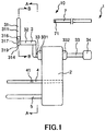
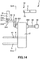
- FIG. 1 is a lateral view depicting a first embodiment of the puncture apparatus of the present invention
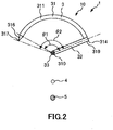
- FIG. 2 is a cross sectional view taken along line A-A in FIG. 1
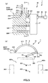
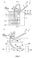
- FIG. 3 is a cross sectional view taken along line B-B in FIG. 1 of a puncture needle of the puncture apparatus according to the invention depicted in FIG. 1
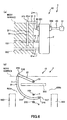
- FIG. 4 is a cross sectional view depicting a state in which a balloon catheter is inserted in a urethral-insertion member of the puncture apparatus depicted in FIG. 1
- FIGS. 5 to 8 are views illustrating an operation procedure of the puncture apparatus depicted in FIG. 1
- FIGS. 9 to 13 are cross sectional views illustrating the operation procedures of the puncture apparatus depicted in FIG. 1 .
- FIG. 5(a) , FIG. 6(a) , FIG. 7(a) and FIG. 8(a) are lateral views;
- FIG. 5(b) is a cross sectional view taken along line C-C in FIG. 5(a) ;
- FIG. 6(b) is a cross sectional view taken along line D-D in of FIG. 6(a) ;
- FIG. 7(b) is a cross sectional view taken along line E-E in FIG. 7(a) ;
- FIG. 8(b) is a cross sectional view taken along line F-F in FIG. 8(a) .
- FIGS. 9 to 13 are views corresponding to the cross sectional view taken along line C-C in FIG. 5(a) .
- FIG. 5(b) , FIG. 6(b) , FIG. 7(b) , FIG. 8(b) and FIGS. 9 to 13 slanting lines for a living body are omitted so as to be easily viewable.
- FIG. 5(b) , FIG. 6(b) , FIG. 7(b) , FIG. 8(b) and FIGS. 9 to 13 in order to facilitate understandings, a puncture member, a pusher, a living body tissue supporting indwelling article and so forth which are originally hidden by the living body and are invisible are depicted.
- the puncture apparatus 1 depicted in the figures is an apparatus to be used for the treatment of woman's urinary incontinence, namely, to be used when a living body tissue supporting indwelling article for the treatment of urinary incontinence is implanted into the inside of the living body.
- the living body tissue supporting indwelling article is a implantable tool for the treatment of woman's urinary incontinence, namely, a tool to be implanted into the living body for supporting the urethra (living body tissue), for example, a tool for supporting, for example, when it is intended to move the urethra to the vaginal wall side, the urethra tension-free or so as to pull the urethra in a direction in which the urethra is spaced away from the vaginal wall.
- urethra living body tissue
- a living body tissue supporting indwelling article 8 includes a main body portion 80 having a belt-like shape, a string 81 fixed to one end portion of the main body portion 80, and another string 82 fixed to the other end portion of the main body portion 80.
- the living body tissue supporting indwelling article 8 is called "sling."
- the main body portion 80 has a net-like form and can be configured, for example, as an article braided in a net-like form (lattice form) of crossing liner bodies, namely, as a braided body having a net-like form.
- the liner bodies may be, for example, those having a circular transverse sectional shape, those having a flattened transverse sectional shape, namely, those of a belt-like form (ribbon form), and so forth.
- constituent material of the main body portion 80 of the living body tissue supporting indwelling article 8 is not limited particularly, and it is possible to use, for example, various kinds of resin materials and the like which have biocompatibility.
- constituent materials of the strings 81 and 82 are not limited particularly, and it is possible to use, for example, various kinds of resin materials, fibers and the like.
- main body portion 80 is not limited to that of a net-like form described hereinabove.
- the puncture apparatus 1 includes a puncture needle 31 for puncturing a living body tissue, a puncture member 3 including a shaft portion 33 and a connection portion 32 for connecting the puncture needle 31 and the shaft portion 33 to each other, and a punctual device 10 including the living body tissue supporting indwelling article 8.
- the connection portion 32 connects the shaft portion 33 and a needle main body 311, to be described later, of the puncture needle 31 to each other.
- the puncture apparatus 1 further includes a urethral-insertion member 4 of a longitudinal shape for being inserted into a urethra, a vaginal-insertion member 5 of a longitudinal shape for being inserted into a vagina, and a supporting member
- the urethral-insertion member 4 is firmly fixed to the supporting member 2.
- the urethral-insertion member 4 may be removably provided on the supporting member 2.
- the urethral-insertion member 4 has a straight tubular shape, and an opening at the proximal end thereof is open at the proximal end face of the supporting member 2.
- a balloon catheter 11 which includes an expandable and contractible balloon 111 at the distal end portion thereof as depicted in FIG. 4 .
- the balloon 111 in a contracted state is indicated by a solid line
- the balloon 111 in an expanded state is indicated by an alternate long and two-short dashes line.
- the balloon 111 of the balloon catheter 11 functions as a restriction unit for restricting the position of the urethral-insertion member 4 in the axial direction (longitudinal direction) inside the urethra. More specifically, when the puncture apparatus 1 is to be used, the balloon 111 is inserted into the bladder of a patient, and the positional relation in the axial direction between the balloon catheter 11 and the urethral-insertion member 4 is fixed. Besides, the balloon 111 is caught by the bladder neck in a state in which the balloon 111 is expanded, and consequently, the position of the urethral-insertion member 4 with respect to the bladder and the urethra is fixed.
- a balloon expanding tool such as, for example, a syringe not depicted is connected to a port not depicted which communicates with a lumen not depicted which communicates with the balloon 111 of the balloon catheter 11. Then, operating fluid supplied from the balloon expanding tool is sent into or extracted from the inside of the balloon 111 thorough the aforementioned lumen to carry out expansion and contraction of the balloon 111.
- the operating fluid for the expansion of the balloon it is possible to use liquid such as, for example, physiological salt solution or gas.
- the balloon catheter 11 for the urination of the patient when the puncture apparatus 1 is to be used.
- a marker 41 is provided at an outer circumferential portion of the urethral-insertion member 4.
- the marker 41 is arranged such that the marker 41 is positioned at the urethral orifice when the urethral-insertion member 4 is inserted into the urethra and the distal end portion of the urethral-insertion member 4 is positioned just in front of the bladder.
- the vaginal-insertion member 5 is firmly fixed to the supporting member 2.
- the vaginal-insertion member 5 may otherwise be removably provided on the supporting member 2.
- the vaginal-insertion member 5 has a form of a straight bar. Further, the distal end portion of the vaginal-insertion member 5 is rounded. Consequently, it is possible to insert the vaginal-insertion member 5 smoothly into the vagina.
- vaginal-insertion member 5 is arranged in a spaced relationship by a predetermined distance from the urethral-insertion member 4 below the urethral-insertion member 4 such that the axial line thereof and the axial line of the urethral-insertion member 4 extend in parallel to each other.
- constituent materials of the vaginal-insertion member 5, the urethral-insertion member 4 and the supporting member 2 are not limited specifically, and it is possible to use, for example, various kinds of resin materials.
- the puncture member 3 is provided for rotation at the shaft portion 33 thereof on the supporting member 2.
- the shaft portion 33 is arranged in a spaced relationship by a predetermined distance from the urethral-insertion member 4 above the urethral-insertion member 4 such that the axial line thereof and the axial line of the urethral-insertion member 4 extend in parallel to each other. Further, as viewed from the axial direction of the shaft portion 33, the shaft portion 33, urethral-insertion member 4 and vaginal-insertion member 5 lie on a straight line.
- the shaft portion 33 passes through the supporting member 2 in the leftward and rightward direction in FIG. 1 .
- a flange 331 and another flange 332 are formed, respectively, with the supporting member 2 interposed therebetween. The movement of the shaft portion 33 in the axial direction with respect to the supporting member 2 is blocked by the flanges 331 and 332.
- the puncture needle 31 includes the needle main body 311 for puncturing a living body tissue, and an extension needle 316 provided for relative movement to the needle main body 311 along a longitudinal direction of the needle main body 311 to puncture a living body tissue.
- the puncture needle 31 is extended by movement of the extension needle 316 in a direction toward the distal end of the needle main body 311 with respect to the needle main body 311.
- the puncture device 10 includes, as extension means for moving the extension needle 316 in the direction toward the distal end of the needle main body 311 with respect to the needle main body 311 to extend the puncture needle 31, a pusher 7 for pushing the extension needle 316 in the direction toward the distal end of the needle main body 311.
- the needle main body 311 has a hollow portion 312 extending from the proximal end to the distal end thereof and has a tubular shape.
- the needle main body 311 has an opening 313, which communicates with the hollow portion 312, at the distal end thereof, and has another opening 314, which communicates with the hollow portion 312, at the proximal end thereof.
- the extension needle 316 is inserted in the hollow portion 312 of the needle main body 311 for movement along a longitudinal direction of the needle main body 311. Further, the extension needle 316 can be removed from the opening 313 of the needle main body 311.
- extension needle 316 has a sharp needle tip 317 at the distal end thereof, and the needle tip 317 protrudes in a direction toward the distal end from the opening 313 of the needle main body 311.
- the state of the puncture needle 31 depicted in FIG. 3 is an initial state of the puncture needle 31, and when the puncture needle 31 is in the initial state, the extension needle 316 is positioned on the most proximal end side with respect to the needle main body 311. Further, in the initial state of the puncture needle 31, the needle tip 317 of the extension needle 316 protrudes in the direction toward the distal end from the opening 313 of the needle main body 311. In particular, the needle tip 317 of the extension needle 316 normally protrudes in the direction toward the distal end from the opening 313 of the needle main body 311.
- the extension needle 316 has a hollow portion 318 extending from the proximal end to the distal end portion thereof, and has, at the proximal end thereof, an opening 319 which communicates with the hollow portion 318.
- the opening 319 configures an entrance for the pusher 7 when the pusher 7 is inserted into the hollow portion 318. It is to be noted that the distal end portion of the extension needle 316 is closed up.
- an attachment portion 315 is formed over a circumference on an outer periphery of a distal end portion of the extension needle 316 such that the distal end of the needle main body 311 attaches to the attachment portion 315 in the initial state depicted in FIG. 3 in which the extension needle 316 is inserted in the hollow portion 312 of the needle main body 311. Consequently, when the shaft portion 33 is moved rotationally clockwise in FIG. 3 to move (rotate) the needle main body 311 clockwise in FIG. 3 , the extension needle 316 moves clockwise in FIG. 3 integrally with the needle main body 311.
- the pusher 7 has an elongated shape and is inserted from the opening 319 into the hollow portion 312 of the needle main body 311, namely, into the hollow portion 318 of the extension needle 316 to push a distal end portion of the extension needle 316 to move the extension needle 316 in the direction toward the distal end thereof.
- the pusher 7 has a transverse sectional shape corresponding to a transverse sectional shape of the hollow portion 318 of the extension needle 316. Further, the pusher 7 has flexibility so as to be compatible with the shape of the needle main body 311 and the extension needle 316. Note that, since the distal end portion of the extension needle 316 is closed up, the distal end portion of the pusher 7 attaches to the distal end portion of the extension needle 316 and can push the distal end portion of the extension needle 316.
- the pusher 7 has, at a distal end portion thereof, a through-hole 71 as an engaging portion for engaging with the living body tissue supporting indwelling article 8.
- the through-hole 71 extends through the pusher 7 in a direction perpendicular to the longitudinal direction of the pusher 7.
- one of the string 81 and the string 82 of the living body tissue supporting indwelling article 8 is inserted and engaged so that the string 81 or the string 82 is held for removal (refer to FIG. 11 ).
- constituent material of the pusher 7 is not limited specifically, and, for example, various resin materials, various metal materials and so forth can be used.
- the pusher 7 When the puncture needle 31 is to be extended, the pusher 7 is inserted into the hollow portion 318 through the opening 319 of the extension needle 316, and the extension needle 316 is pushed by the pusher 7 to move in the direction toward the distal end.
- the extension needle 316 since the extension needle 316 is positioned on the inner circumference side of the needle main body 311, the contact area between the extension needle 316 and the living body tissue can be made comparatively small and the puncture needle 31 can be extended readily and smoothly. Further, the burden on the patient can be reduced.
- the puncture needle 31, namely, the needle main body 311 and the extension needle 316 are curved in an arc centered at the shaft portion 33 along a longitudinal direction thereof. Further, in FIG. 1 , an axial line of the puncture needle 31 and an axial line of the shaft portion 33 cross orthogonally with each other. Consequently, when the puncture member 3 moves rotationally, the needle tip 317 of the extension needle 316 moves along the arc in a plane perpendicular to the axial line of the shaft portion 33, namely, in a plane having a normal line on the axial line.
- the needle tip 317 of the extension needle 316 is directed toward the counterclockwise direction in FIG. 2 .
- the direction of the needle tip 317 is not limited, and the needle tip 317 may be directed otherwise toward the clockwise direction in FIG. 2 .
- the puncture needle 31 is arranged on the proximal end side in the axial direction of the urethral-insertion member 4 with respect to the distal end portion of the urethral-insertion member 4.
- the puncture needle 31 may otherwise be arranged at the same position as that of the distal end portion of the urethral-insertion member 4 in the axial direction of the urethral-insertion member 4, or may be arranged at the distal end side with respect to the distal end portion of the urethral-insertion member 4.
- the supporting member 2 restricts the positional relation between the puncture member 3 (puncture needle 31) and the urethral-insertion member 4 such that, when the shaft portion 33, namely, the puncture member 3, moves rotationally and the puncture needle 31 punctures the living body tissue, the needle tip 317 of the extension needle 316 passes a farther-position side from the center 310 of the puncture needle 31 (extension needle 316) than the urethral-insertion member 4 or an extension line of the urethral-insertion member 4, namely, passes below the urethral-insertion member 4 or an extension line of the same.
- the center 310 of the puncture needle 31 is the center of the arc of the puncture needle 31.
- the center 310 of the puncture needle 31 is the center of the rotational movement of the puncture needle 31 (puncture member 3).
- the supporting member 2 restricts the positional relation between the puncture member 3 (puncture needle 31) and the vaginal-insertion member 5 such that, when the shaft portion 33, namely, the puncture member 3 moves rotationally and the puncture needle 31 punctures the biological issue, the needle tip 317 of the extension needle 316 does not collide with the vaginal-insertion member 5 and an extension line of the same.
- the supporting member 2 restricts the positional relation among the puncture member 3 (puncture needle 31), urethral-insertion member 4 and vaginal-insertion member 5 such that, when the puncture member 3 moves rotationally and the puncture needle 31 punctures the living body tissue, the needle tip 317 of the extension needle 316 passes a position between the urethral-insertion member 4 or the extension line of the same and the vaginal-insertion member 5 or the extension line of the same.
- the puncture needle 31 can puncture the living body tissue avoiding the urethra and the vaginal wall, and it is possible to prevent the puncture needle 31 from puncturing the urethra and from puncturing the vaginal wall. Further, since the puncture needle 31 is extended, it can cope also with a patient whose thickness of the subcutaneous tissue is comparatively great.
- the orbit of the needle tip 317 of the extension needle 316 is determined, also the operator itself can be prevented from being punctured at its fingertip by the puncture needle 31 and is safe.
- the center angle ⁇ 1 of the above-described arc of the needle main body 311, the center angle ⁇ 2 of the arc of the extension needle 316 and the center angle ⁇ 3 of the arc of the puncture needle 31 in a state in which the puncture needle 31 is extended most are not limited specifically but can be set suitably in accordance with various conditions.
- the angles mentioned are set such that, when the living body tissue is punctured by the puncture needle 31, the puncture needle 31 can enter into the body of the patient from the body surface on one side, pass below the urethra and protrude to outside of the body from the body surface on the other side.
- ⁇ 3 minus ⁇ 1 equals to ⁇ 2.
- the center angle ⁇ 1 of the arc of the needle main body 311 preferably is 95 to 180°, and more preferably is 120 to 150°.
- the center angle ⁇ 3 of the arc of the puncture needle 31 in the state in which the puncture needle 31 is extended most preferably is 190 to 270°, and more preferably is 200 to 250°.
- the puncture needle 31 can reliably enter into the body from the body face on one side of the patient, pass below the urethra and protrude to the outside of the body from the body surface on the other side.
- a grip unit 34 is provided as an operation unit for operating the puncture member 3 rotationally.
- the shape of the grip unit 34 is a rectangular solid.
- the grip unit 34 is gripped by the fingers of a hand and is moved rotationally in a predetermined direction. Note that it is needless to say that the shape of the grip unit 34 is not to be limited to this.
- connection portion 32 in the present embodiment has an L shape.
- a distal end portion of the connection portion 32 is fixed to a proximal end portion of the needle main body 311, and a proximal end portion of the connection portion 32 is fixed to a distal end portion of the shaft portion 33.
- the puncture needle 31 and the shaft portion 33 can be spaced by a predetermined distance from each other in the axial direction of the shaft portion 33.
- connection portion 32 and the needle main body 311 may otherwise be integrated with each other, and the connection portion 32 and the shaft portion 33 may otherwise be integrated with each other. Further, the needle main body 311, connection portion 32 and shaft portion 33 may otherwise be integrated with one another.
- connection portion 32 is not limited to this.
- constituent material of the puncture member 3 is not limited specifically, and such various metal materials as stainless steel, aluminum or aluminum alloy and titanium or titanium alloy can be used as the constituent material of the puncture member 3.
- the puncture apparatus 1 is mounted on a patient as depicted in FIG. 5 . More specifically, the urethral-insertion member 4 of the puncture apparatus 1 is inserted into the urethra 100 of the patient and the vaginal-insertion member 5 is inserted into the vagina 200 of the patient. At the time, the insertion is carried out such that the marker 41 is positioned at the urethral orifice or on the front side of the urethral orifice. Consequently, the distal end portion of the urethral-insertion member 4 can be arranged on the front side of the bladder.
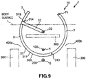
- the grip unit 34 is grasped as depicted in FIG. 6 and rotationally moves the puncture member 3 counterclockwise in FIG. 6(b) .
- the needle tip 317 of the puncture needle 31 moves counterclockwise in FIG. 6(b) along the arc thereof; punctures the body surface at an inguinal region of the patient on the left side in FIG. 6(b) or at a region in the vicinity of the same; enters into the body; passes an obturator foramen 400a of a pelvis 300; passes below the urethra 100, namely, passes between the urethra 100 and the vagina 200; and passes an obturator foramen 400b of the pelvis 300.
- the pusher 7 is inserted into the hollow portion 318 through the opening 319 of the extension needle 316 as depicted in FIGS. 7 and 8 , and the distal end portion of the extension needle 316 is pushed in a direction toward the distal end by the pusher 7 so that the extension needle 316 is moved in the direction toward the distal end.
- the needle tip 317 of the extension needle moves counterclockwise in FIG. 8(b) along the arc thereof and protrudes to the outside of the body from an inguinal region on the right side in FIG. 8(b) or at a region in the vicinity of the same.
- the distal end portion of the pusher 7 protrudes to the outside of the body from the body surface together with the extension needle 316. Consequently, in the patient, a through-hole 500 is formed which extends from the body surface at an inguinal region on the left side in FIG. 8(b) or at a region in the vicinity of the same to the body surface at an inguinal region on the right side in FIG.
- the living body tissue supporting indwelling article 8 is implanted in the through-hole 500.
- extension needle 316 is pulled in a direction toward the distal end so as to be removed from the opening 313 of the needle main body 311 as depicted in FIG. 9 .
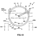
- the grip unit 34 is grasped and the puncture member 3 is rotated clockwise in FIG. 10 .
- the distal end portion of the needle main body 311 moves along the arc thereof clockwise in FIG. 10 ; passes below the urethra 100, namely, passes between the urethra 100 and the vagina 200; passes the obturator foramen 400a of the pelvis 300; and goes out to the outside of the body from the inguinal region on the left side in FIG. 10 or from the body surface in a region in the vicinity of the same. In other words, the needle main body 311 is pulled out to the outside of the body.
- an end portion of one of the strings 81 and 82 of the living body tissue supporting indwelling article 8 in the configuration depicted in FIG. 11 , an end portion of the string 81, is inserted into the through-hole 71 of the pusher 7 as depicted in FIG. 11 . Consequently, the end portion of the string 81 is engaged with the through-hole 71 of the pusher 7 and is held for removal by the distal end portion of the pusher 7.
- the puncture apparatus 1 is removed from the patient.
- the urethral-insertion member 4 is pulled out from within the urethra 100 and the vaginal insertion member 5 is pulled out from within the vagina 200 of the patient.
- the string 81 is pulled while the string 82 is pulled, and the main body portion 80 of the living body tissue supporting indwelling article 8 is inserted into the through-hole 500 formed in the patient. Then, while the end portion of the main body portion 80 on the right side in FIG. 12 is left outside the body, the end portion of the main body portion 80 on the left side in FIG. 12 is pulled out from the through-hole 500 to the outside of the body.
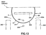
- the strings 81 and 82 are individually pulled by predetermined force as depicted in FIG. 13 to adjust the position of the main body portion 80 of the living body tissue supporting indwelling article 8 with respect to the urethra 100. Then, unnecessary portions of the living body tissue supporting indwelling article 8 are cut away and predetermined treatment is carried out, thereby ending the manual procedure.
- the puncture apparatus 1 when the living body tissue supporting indwelling article 8 is to be indwelled, the indwelling operation can be carried out only by a low invasive manual procedure such as puncturing of the puncture needle 31. Since it is not necessary to carry out a high invasive incision or the like, the burden on the patient is light and also the safety of the patient is high.
- the puncture needle 31 it is possible to puncture the living body by the puncture needle 31 avoiding the urethra and the vaginal wall, and it is possible to prevent the puncture needle 31 from puncturing the urethra and puncturing the vaginal wall. Therefore, safety can be achieved. Further, since the puncture needle 31 extends, it can cope also with a patient who has a comparatively thick subcutaneous issue. Also the operator itself can prevent its fingertip from being punctured by the puncture needle 31. Therefore, safety can be achieved.
- the living body tissue supporting indwelling article 8 can be implanted in very high safety and can with certainty.
- the puncture hole formed in the patient by the puncture needle 31 is a through-hole
- the puncture hole is not limited to this and may not extend through the patient.
- the urethral-insertion member is not limited to that of a tubular shape, and may be, for example, a solid member or may be a hollow member which is closed up at one or both of the distal end portion and the proximal end portion thereof.
- an expandable and contractible balloon may be provided as a restriction unit for restricting the position of the urethral-insertion member in the axial direction inside the urethra.
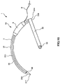
- FIG. 14 is a side elevational view depicting a second embodiment of the puncture apparatus of the present disclosure
- FIG. 15 is a sectional view taken along line G-G in FIG. 14 .
- the puncture needle 31 namely, the needle main body 311 and the extension needle 316
- the puncture needle 31 have a flattened shape as viewed in a longitudinal direction thereof.
- transverse sectional shapes of the needle main body 311 and the extension needle 316 correspond to the transverse sectional shape of the main body portion 80 of the living body tissue supporting indwelling article 8.
- the puncture apparatus 1 can form, in a patient, a through-hole 500 of a shape corresponding to that of the main body portion 80 of the living body tissue supporting indwelling article 8, and the living body tissue supporting indwelling article 8 can be implanted more readily and appropriately.
- FIG. 16 is a sectional view depicting a third embodiment of the puncture apparatus of the present invention.
- FIG. 16 corresponds to FIG. 2 for the first embodiment and depicts a portion of the puncture member.
- the puncture apparatus 1 of the third embodiment includes a sheath 6 of a tubular shape provided for movement along a longitudinal direction of the puncture needle 31 of the puncture member 3, and a pusher 9 for pushing the sheath 6 to move in a direction toward the distal end of the puncture needle 31.
- the length of the sheath 6 is set shorter than that of the needle main body 311. Further, the sheath 6 has a shape corresponding to a portion of the needle main body 311 and is curved in an arc.
- a pusher similar to the pusher 7 in the first embodiment can be used. Further, a distal end as one end portion of the pusher 9 is fixed to a proximal end portion of the sheath 6. Further, graduations not depicted which indicate the position of the sheath 6 with respect to the puncture needle 31 are provided on the pusher 9.
- grooves 35 and 36 are formed on an outer circumferential face of the needle main body 311 and the extension needle 316 along a longitudinal direction of the same.
- the groove 35 and the groove 36 are formed at positions similar to each other and pass each other when the extension needle 316 is moved in a direction toward the distal end of the needle main body 311 with respect to the needle main body 311.
- the grooves 35 and 36 in the present embodiment individually have a straight shape, the shape of the grooves 35 and 36 is not limited to this, and some other shape such as, for example, a spiral shape may be applied.
- the puncture apparatus 1 for example, if a blood vessel or the like of a patient is punctured by the needle tip 317 of the extension needle of the puncture needle 31 and the patient suffers from bleeding, then the blood flows in a direction toward the proximal end along the grooves 35 and 36. In particular, back flash of the blood occurs. Consequently, it can be grasped that the living body of the patient is bleeding, namely, that a blood vessel or the like of the patient has been punctured by the needle tip 317 of the extension needle.
- the sheath 6 would be pushed in a direction toward the distal end by the pusher 9 so as to move in the direction toward the distal end along the puncture needle 31 until the sheath 6 is arranged at the location at which the patient is bleeding. Consequently, the bleeding can be stopped.
- the sheath 6 may have, for example, a lumen along which liquid such as medical solution is to flow. Further, on a side face of the sheath 6, one or a plurality of side holes communicating with the lumen may be formed.
- the means for stopping bleeding is not limited to the sheath 6, and, for example, an expandable and contractible balloon may be provided on the sheath 6.
- the puncture device and the puncture apparatus of the present invention have been described on the basis of the embodiments depicted in the drawings, the present invention is not limited to them, and the configuration of each unit can be replaced with an arbitrary configuration having a similar function. Further, other arbitrary constructions may be added to the present invention.
- the puncture needle is not limited to this, and, for example, the needle main body may be inserted in the hollow portion of the extension needle.
- the outside-inside positional relationship of the needle main body and the extension needle may be reverse to that in the embodiments.
- one of the extension needle and the needle main body may be solid.
- the extension needle may be inseparable from the needle main body.
- the puncture needle namely, the needle main body and the extension needle, may individually have a linear shape.
- the extension means may be configured such that the extension means pushes the proximal end of the extension needle to move the extension needle.
- the extension means may be fixedly mounted on or integrated with the extension needle.
- the extension means may be fixedly mounted on or integrated with the proximal end side of the extension needle.
- the living body tissue supporting indwelling article may be accommodated in the hollow portion of the puncture needle.
- the puncture device and the puncture apparatus of the present disclosure are applied to an apparatus which is used when a living body tissue supporting indwelling article which can be implanted for the treatment of the woman's urinary incontinence is implanted into the living body.
- the application of the puncture device and the puncture apparatus of the present disclosure is not limited to this.
- the target of the application of the present disclosure includes an excretory disorder along with the weakening of the pelvic floor muscle group (urinary urgency, frequent urination, urinary incontinence, fecal incontinence, urinary retention, dysuria or the like), and a pelvic floor disorder including pelvic organ prolapse, vesicovaginal fistula, urethrovaginal fistula, pelvic pain or the like.
- pelvic organ prolapse there are include disorders of cystocele, enterocele, rectocele, hysterocele and the like.
- bladder, vagina, uterus, bowel and the like there are included bladder, vagina, uterus, bowel and the like.
- lessactive tissues there are included bones, muscles, fascias, ligaments and the like.
- pelvic floor disorders there are included an obturator fascia, a coccygeus fascia, a cardinal ligament, an uterosacral ligament, a sacrotuberous ligament and the like.
- a retropubic sling surgery for the procedure for interlocking an overactive tissue in the pelvic floor disorder with the lessactive tissue, there are included a retropubic sling surgery, a transobturator sling surgery (transobturator sling surgery, transobturator tape: TOT), a tension-free vaginal mesh (Tension-free Vaginal Mesh: TVM) surgery, a uterosacral ligament suspension (Uterosacral Ligament Suspension: USLS) surgery, a sacrospinous ligament fixation (Sacrospinous Ligament Fixation: SSLF) surgery, an iliococcygeus fascia fixation surgery, a coccygeus fascia fixation surgery, and the like.
- a puncture device of the present disclosure includes:
- a puncture apparatus of the present disclosure includes:
- the puncture device and the puncture apparatus can cope also with a patient who has a comparatively thick subcutaneous tissue.
- the puncture apparatus includes the restriction means for restricting the positional relation between the puncture needle and the urethral-insertion member such that, when the shaft portion rotationally moves and the puncture needle punctures the living body tissue, the needle tip of the extension needle passes the farther-position side from the center of a portion, which is curved in an arc, of the extension needle, than the urethral-insertion member, for example, when the puncture apparatus is to be used for the treatment of woman's urinary incontinence, the urethral-insertion member of the puncture apparatus is inserted into a urethra, and the puncture needle is rotationally moved so that the living body is punctured by the puncture needle.
- the puncture needle can puncture the living body avoiding the urethra. Consequently, the puncture needle can be prevented from puncturing the urethra. Further, it is possible to prevent a fingertip of the operator from being punctured by the puncture needle.
- the puncture needle can be extended, the puncture device and the puncture apparatus can cope even with a patient who has a comparatively thick subcutaneous tissue.
- the living body tissue supporting indwelling article for the treatment of urinary incontinence when the living body tissue supporting indwelling article for the treatment of urinary incontinence is to be implanted, no incision of the vaginal wall is required, and the living body tissue supporting indwelling article can be implanted by a low invasive manual procedure. Further, such a situation that, as in a case in which the vagina is incised, the living body tissue supporting indwelling article is exposed to the inside of the vagina through a wound caused by the incision or that such complications as an infection from the wound occur can be prevented. Therefore, the living body tissue supporting indwelling article can be implanted in very high safety and with certainty.
- the present disclosure has industrial applicability.
Landscapes
- Health & Medical Sciences (AREA)
- Life Sciences & Earth Sciences (AREA)
- Surgery (AREA)
- Veterinary Medicine (AREA)
- Animal Behavior & Ethology (AREA)
- Public Health (AREA)
- General Health & Medical Sciences (AREA)
- Engineering & Computer Science (AREA)
- Biomedical Technology (AREA)
- Heart & Thoracic Surgery (AREA)
- Molecular Biology (AREA)
- Nuclear Medicine, Radiotherapy & Molecular Imaging (AREA)
- Medical Informatics (AREA)
- Pathology (AREA)
- Vascular Medicine (AREA)
- Transplantation (AREA)
- Cardiology (AREA)
- Oral & Maxillofacial Surgery (AREA)
- Reproductive Health (AREA)
- Urology & Nephrology (AREA)
- Gynecology & Obstetrics (AREA)
- Pregnancy & Childbirth (AREA)
- Surgical Instruments (AREA)
Claims (10)
- Punktionsvorrichtung (10) umfassend:eine Punktionsnadel (31) miteinem Nadelhauptkörper (311) zum Punktieren eines lebenden Körpergewebes, undeine ausfahrbare Nadel (316), die in den Nadelhauptkörper (311) einsetzbar ist und für eine Bewegung relativ zu dem Nadelhauptkörper (311) entlang einer Längsrichtung des Nadelhauptkörpers (311) zum Punktieren des lebenden Körpergewebes vorgesehen ist; undein Ausfahrmittel zum Bewegen der ausfahrbaren Nadel (316) in eine Richtung zu einem distalen Ende des Nadelhauptkörpers (311) in Bezug auf den Nadelhauptkörper (311), um die Punktionsnadel (31) auszufahren,dadurch gekennzeichnet, dass die ausfahrbare Nadel (316) einen hohlen Abschnitt (318) besitzt, der sich vom proximalen Ende zum distalen Ende der Nadel erstreckt, und das Ausfahrmittel in den hohlen Abschnitt (318) der ausfahrbaren Nadel (316) eingesetzt ist, um einen distalen Endabschnitt der ausfahrbaren Nadel (316) zu schieben, um die ausfahrbare Nadel (316) zu bewegen.
- Punktionsvorrichtung (10) nach Anspruch 1,
wobei der Nadelhauptkörper (311) einen hohlen Abschnitt (312) besitzt und die ausfahrbare Nadel (316) in den hohlen Abschnitt (312, 318) des Nadelhauptkörpers (311) eingesetzt ist, um sich entlang der Längsrichtung des Nadelhauptkörpers (311) zu bewegen. - Punktionsvorrichtung (10) nach Anspruch 2,
wobei der Nadelhauptkörper (311) an seinem distalen Ende eine Öffnung (313, 314, 319) besitzt, die mit dem hohlen Abschnitt (312) in Verbindung steht,
und die ausfahrbare Nadel (316) an ihrem distalen Ende eine Nadelspitze (317) besitzt, die in der Lage ist, das lebende Körpergewebe zu punktieren, wobei die Nadelspitze (317) aus der Öffnung (313, 314, 319) des Nadelhauptkörpers (311) herausragt, wenn die ausfahrbare Nadel (316) auf der ganz proximal gelegenen Stirnseite in Bezug auf den Nadelhauptkörper (311) positioniert ist. - Punktionsvorrichtung (10) nach Anspruch 2 oder 3, wobei das Ausfahrmittel eine langgestreckte Form besitzt und in den hohlen Abschnitt (312) des Nadelhauptkörpers (311) eingesetzt ist, um die ausfahrbare Nadel (316) zu schieben, um die ausfahrbare Nadel (316) zu bewegen.
- Punktionsvorrichtung (10) nach einem der Ansprüche 1 bis 4, ferner umfassend einen langgestreckten, lebendes Körpergewebe stützenden Verweilgegenstand (8), der in einen lebenden Körper implantiert werden soll und ein lebendes Körpergewebe stützt.
- Punktionsvorrichtung (10) nach Anspruch 5,
wobei das Ausfahrmittel an seinem distalen Endabschnitt einen Eingriffsabschnitt besitzt, der in den lebendes Körpergewebe stützenden Verweilgegenstand (8) eingreifen soll. - Punktionsvorrichtung (10) nach einem der Ansprüche 1 bis 6, wobei die ausfahrbare Nadel (316) von dem Nadelhauptkörper (311) getrennt werden kann.
- Punktionsvorrichtung (10) nach einem der Ansprüche 1 bis 7, wobei der Nadelhauptkörper (311) und die ausfahrbare Nadel (316) bei Betrachtung in ihrer Längsrichtung jeweils eine abgeflachte Form haben.
- Punktionsvorrichtung (10) nach einem der Ansprüche 1 bis 8, wobei der Nadelhauptkörper (311) und die ausfahrbare Nadel (316) jeweils einen entlang ihrer Längsrichtung gebogenen Abschnitt besitzen.
- Punktionsvorrichtung (10) nach Anspruch 9,
wobei der Nadelhauptkörper (311) und die ausfahrbare Nadel (316) jeweils für eine Drehbewegung vorgesehen sind.
Applications Claiming Priority (2)
| Application Number | Priority Date | Filing Date | Title |
|---|---|---|---|
| JP2012068399 | 2012-03-23 | ||
| PCT/JP2013/057061 WO2013141119A1 (ja) | 2012-03-23 | 2013-03-13 | 穿刺器具および穿刺装置 |
Publications (3)
| Publication Number | Publication Date |
|---|---|
| EP2829236A1 EP2829236A1 (de) | 2015-01-28 |
| EP2829236A4 EP2829236A4 (de) | 2016-03-02 |
| EP2829236B1 true EP2829236B1 (de) | 2019-06-26 |
Family
ID=49222579
Family Applications (1)
| Application Number | Title | Priority Date | Filing Date |
|---|---|---|---|
| EP13764048.8A Active EP2829236B1 (de) | 2012-03-23 | 2013-03-13 | Punktionsinstrument und punktionsvorrichtung |
Country Status (5)
| Country | Link |
|---|---|
| US (1) | US9955995B2 (de) |
| EP (1) | EP2829236B1 (de) |
| JP (1) | JP6130355B2 (de) |
| CN (1) | CN104203120A (de) |
| WO (1) | WO2013141119A1 (de) |
Families Citing this family (10)
| Publication number | Priority date | Publication date | Assignee | Title |
|---|---|---|---|---|
| US8911464B2 (en) * | 2012-03-23 | 2014-12-16 | Terumo Kabushiki Kaisha | Puncture apparatus |
| EP2862521A4 (de) * | 2012-06-14 | 2016-04-06 | Terumo Corp | Punktionsvorrichtung |
| WO2014162422A1 (ja) * | 2013-04-01 | 2014-10-09 | テルモ株式会社 | 穿刺針組立体 |
| WO2014162429A1 (ja) * | 2013-04-01 | 2014-10-09 | テルモ株式会社 | 挿入具および穿刺装置 |
| US10265097B2 (en) * | 2014-09-25 | 2019-04-23 | Cardiac Pacemakers, Inc. | Needle assembly with retractable cutting edge |
| KR102883778B1 (ko) | 2017-09-22 | 2025-11-12 | 더 트러스티스 오브 더 유니버시티 오브 펜실베니아 | Ii형 점액다당류증의 치료를 위한 유전자 요법 |
| TR202012933A2 (tr) * | 2020-08-17 | 2020-10-21 | Orhan Seyfi Aksakal | Geliştirilmiş Güvenli Doku Tünel Açıcısı |
| CN112168311B (zh) * | 2020-10-16 | 2022-03-08 | 王芳 | 一种产科临产用防外流破膜装置 |
| CN117653230A (zh) * | 2022-09-01 | 2024-03-08 | 江苏风和医疗器材股份有限公司 | 用于外科手术的缝合器及穿刺器 |
| CN118648958B (zh) * | 2024-08-19 | 2024-12-20 | 苏州市美新迪斯医疗科技有限公司 | 一种环甲膜穿刺装置及其使用方法 |
Family Cites Families (14)
| Publication number | Priority date | Publication date | Assignee | Title |
|---|---|---|---|---|
| DK166600B1 (da) * | 1991-01-17 | 1993-06-21 | Therkel Bisgaard | Vaerktoejssaet til brug ved suturering i dybe operationsaabninger eller legemshulrum |
| CA2100238A1 (en) * | 1992-08-03 | 1994-02-04 | Michael Haroldsen | Needles made from non-round stock |
| US5458609A (en) * | 1992-09-04 | 1995-10-17 | Laurus Medical Corporation | Surgical needle and retainer system |
| SE503271C2 (sv) | 1994-08-30 | 1996-04-29 | Medscand Ab | Instrumentarium för behandling av urininkontinens hos kvinnor samt sätt för sådan behandling |
| EP1402822B1 (de) * | 1997-02-13 | 2013-10-02 | Boston Scientific Limited | Perkutane und hiatale Geräte zur Verwendung bei Minimal-Invasierbeckenchirurgie |
| AU6329498A (en) * | 1997-02-13 | 1998-09-08 | Boston Scientific Ireland Limited, Barbados Head Office | Percutaneous and hiatal devices and methods for use in minimally invasive pelvicsurgery |
| US6596001B2 (en) * | 2000-05-01 | 2003-07-22 | Ethicon, Inc. | Aiming device for surgical instrument and method for use for treating female urinary incontinence |
| CN1277512C (zh) * | 2000-11-20 | 2006-10-04 | 伊西康公司 | 治疗女性尿失禁的医用器械及方法 |
| US6911003B2 (en) | 2002-03-07 | 2005-06-28 | Ams Research Corporation | Transobturator surgical articles and methods |
| JP4476630B2 (ja) | 2002-03-07 | 2010-06-09 | エーエムエス・リサーチ・コーポレーション | 閉鎖膜経由での手術器具および方法 |
| US8439820B2 (en) * | 2004-05-06 | 2013-05-14 | Boston Scientific Scimed, Inc. | Systems and methods for sling delivery and placement |
| EP1948073B1 (de) * | 2005-11-14 | 2014-03-19 | C.R.Bard, Inc. | Bandankersystem |
| US8974367B2 (en) * | 2006-10-03 | 2015-03-10 | Boston Scientific Scimed, Inc. | Coaxial device for delivering an implant to a patient's pelvic region |
| EP2194913A1 (de) * | 2007-09-21 | 2010-06-16 | AMS Research Corporation | Beckenbodenbehandlungen und relevante werkzeuge und implantate |
-
2013
- 2013-03-13 EP EP13764048.8A patent/EP2829236B1/de active Active
- 2013-03-13 JP JP2014506170A patent/JP6130355B2/ja not_active Expired - Fee Related
- 2013-03-13 CN CN201380015768.XA patent/CN104203120A/zh active Pending
- 2013-03-13 WO PCT/JP2013/057061 patent/WO2013141119A1/ja not_active Ceased
-
2014
- 2014-09-23 US US14/494,384 patent/US9955995B2/en active Active
Non-Patent Citations (1)
| Title |
|---|
| None * |
Also Published As
| Publication number | Publication date |
|---|---|
| EP2829236A4 (de) | 2016-03-02 |
| WO2013141119A1 (ja) | 2013-09-26 |
| CN104203120A (zh) | 2014-12-10 |
| JPWO2013141119A1 (ja) | 2015-08-03 |
| US9955995B2 (en) | 2018-05-01 |
| JP6130355B2 (ja) | 2017-05-17 |
| US20150011820A1 (en) | 2015-01-08 |
| EP2829236A1 (de) | 2015-01-28 |
Similar Documents
| Publication | Publication Date | Title |
|---|---|---|
| EP2829236B1 (de) | Punktionsinstrument und punktionsvorrichtung | |
| JP6051226B2 (ja) | 穿刺装置 | |
| US10548702B2 (en) | Systems and methods for sling delivery and placement | |
| JP6092367B2 (ja) | 穿刺装置 | |
| US9999491B2 (en) | Puncture device and puncture apparatus | |
| US20160106529A1 (en) | Systems and methods employing a push tube for delivering a urethral sling | |
| US9498210B2 (en) | Puncture apparatus | |
| US9017357B1 (en) | Puncture apparatus | |
| JP2015058121A (ja) | インプラントおよびインプラントの留置方法 | |
| US20160287286A1 (en) | Urethral-insertion device | |
| US9011475B1 (en) | Puncture apparatus | |
| WO2014162425A1 (ja) | 医療用具 | |
| WO2014162423A1 (ja) | 医療用具 | |
| JP2015058323A (ja) | インプラントの留置方法 | |
| WO2015137116A1 (ja) | 穿刺部材 | |
| WO2015041140A1 (ja) | 穿刺装置および穿刺方法 | |
| US20160193024A1 (en) | Medical tube assembly and puncture apparatus | |
| WO2014162424A1 (ja) | チューブ組立体 | |
| US20170000596A1 (en) | Puncture member |
Legal Events
| Date | Code | Title | Description |
|---|---|---|---|
| PUAI | Public reference made under article 153(3) epc to a published international application that has entered the european phase |
Free format text: ORIGINAL CODE: 0009012 |
|
| 17P | Request for examination filed |
Effective date: 20140912 |
|
| AK | Designated contracting states |
Kind code of ref document: A1 Designated state(s): AL AT BE BG CH CY CZ DE DK EE ES FI FR GB GR HR HU IE IS IT LI LT LU LV MC MK MT NL NO PL PT RO RS SE SI SK SM TR |
|
| AX | Request for extension of the european patent |
Extension state: BA ME |
|
| DAX | Request for extension of the european patent (deleted) | ||
| RIC1 | Information provided on ipc code assigned before grant |
Ipc: A61B 17/00 20060101AFI20151002BHEP Ipc: A61B 17/04 20060101ALI20151002BHEP |
|
| RA4 | Supplementary search report drawn up and despatched (corrected) |
Effective date: 20160128 |
|
| RIC1 | Information provided on ipc code assigned before grant |
Ipc: A61B 17/00 20060101AFI20160122BHEP Ipc: A61B 17/04 20060101ALI20160122BHEP |
|
| R17P | Request for examination filed (corrected) |
Effective date: 20140912 |
|
| GRAP | Despatch of communication of intention to grant a patent |
Free format text: ORIGINAL CODE: EPIDOSNIGR1 |
|
| STAA | Information on the status of an ep patent application or granted ep patent |
Free format text: STATUS: GRANT OF PATENT IS INTENDED |
|
| INTG | Intention to grant announced |
Effective date: 20190118 |
|
| GRAS | Grant fee paid |
Free format text: ORIGINAL CODE: EPIDOSNIGR3 |
|
| GRAA | (expected) grant |
Free format text: ORIGINAL CODE: 0009210 |
|
| STAA | Information on the status of an ep patent application or granted ep patent |
Free format text: STATUS: THE PATENT HAS BEEN GRANTED |
|
| AK | Designated contracting states |
Kind code of ref document: B1 Designated state(s): AL AT BE BG CH CY CZ DE DK EE ES FI FR GB GR HR HU IE IS IT LI LT LU LV MC MK MT NL NO PL PT RO RS SE SI SK SM TR |
|
| REG | Reference to a national code |
Ref country code: GB Ref legal event code: FG4D |
|
| REG | Reference to a national code |
Ref country code: CH Ref legal event code: EP |
|
| REG | Reference to a national code |
Ref country code: AT Ref legal event code: REF Ref document number: 1147378 Country of ref document: AT Kind code of ref document: T Effective date: 20190715 |
|
| REG | Reference to a national code |
Ref country code: DE Ref legal event code: R096 Ref document number: 602013057117 Country of ref document: DE |
|
| REG | Reference to a national code |
Ref country code: IE Ref legal event code: FG4D |
|
| REG | Reference to a national code |
Ref country code: NL Ref legal event code: MP Effective date: 20190626 |
|
| PG25 | Lapsed in a contracting state [announced via postgrant information from national office to epo] |
Ref country code: FI Free format text: LAPSE BECAUSE OF FAILURE TO SUBMIT A TRANSLATION OF THE DESCRIPTION OR TO PAY THE FEE WITHIN THE PRESCRIBED TIME-LIMIT Effective date: 20190626 Ref country code: NO Free format text: LAPSE BECAUSE OF FAILURE TO SUBMIT A TRANSLATION OF THE DESCRIPTION OR TO PAY THE FEE WITHIN THE PRESCRIBED TIME-LIMIT Effective date: 20190926 Ref country code: AL Free format text: LAPSE BECAUSE OF FAILURE TO SUBMIT A TRANSLATION OF THE DESCRIPTION OR TO PAY THE FEE WITHIN THE PRESCRIBED TIME-LIMIT Effective date: 20190626 Ref country code: SE Free format text: LAPSE BECAUSE OF FAILURE TO SUBMIT A TRANSLATION OF THE DESCRIPTION OR TO PAY THE FEE WITHIN THE PRESCRIBED TIME-LIMIT Effective date: 20190626 Ref country code: HR Free format text: LAPSE BECAUSE OF FAILURE TO SUBMIT A TRANSLATION OF THE DESCRIPTION OR TO PAY THE FEE WITHIN THE PRESCRIBED TIME-LIMIT Effective date: 20190626 Ref country code: LT Free format text: LAPSE BECAUSE OF FAILURE TO SUBMIT A TRANSLATION OF THE DESCRIPTION OR TO PAY THE FEE WITHIN THE PRESCRIBED TIME-LIMIT Effective date: 20190626 |
|
| REG | Reference to a national code |
Ref country code: LT Ref legal event code: MG4D |
|
| PG25 | Lapsed in a contracting state [announced via postgrant information from national office to epo] |
Ref country code: RS Free format text: LAPSE BECAUSE OF FAILURE TO SUBMIT A TRANSLATION OF THE DESCRIPTION OR TO PAY THE FEE WITHIN THE PRESCRIBED TIME-LIMIT Effective date: 20190626 Ref country code: BG Free format text: LAPSE BECAUSE OF FAILURE TO SUBMIT A TRANSLATION OF THE DESCRIPTION OR TO PAY THE FEE WITHIN THE PRESCRIBED TIME-LIMIT Effective date: 20190926 Ref country code: GR Free format text: LAPSE BECAUSE OF FAILURE TO SUBMIT A TRANSLATION OF THE DESCRIPTION OR TO PAY THE FEE WITHIN THE PRESCRIBED TIME-LIMIT Effective date: 20190927 Ref country code: LV Free format text: LAPSE BECAUSE OF FAILURE TO SUBMIT A TRANSLATION OF THE DESCRIPTION OR TO PAY THE FEE WITHIN THE PRESCRIBED TIME-LIMIT Effective date: 20190626 |
|
| REG | Reference to a national code |
Ref country code: AT Ref legal event code: MK05 Ref document number: 1147378 Country of ref document: AT Kind code of ref document: T Effective date: 20190626 |
|
| PG25 | Lapsed in a contracting state [announced via postgrant information from national office to epo] |
Ref country code: RO Free format text: LAPSE BECAUSE OF FAILURE TO SUBMIT A TRANSLATION OF THE DESCRIPTION OR TO PAY THE FEE WITHIN THE PRESCRIBED TIME-LIMIT Effective date: 20190626 Ref country code: CZ Free format text: LAPSE BECAUSE OF FAILURE TO SUBMIT A TRANSLATION OF THE DESCRIPTION OR TO PAY THE FEE WITHIN THE PRESCRIBED TIME-LIMIT Effective date: 20190626 Ref country code: SK Free format text: LAPSE BECAUSE OF FAILURE TO SUBMIT A TRANSLATION OF THE DESCRIPTION OR TO PAY THE FEE WITHIN THE PRESCRIBED TIME-LIMIT Effective date: 20190626 Ref country code: NL Free format text: LAPSE BECAUSE OF FAILURE TO SUBMIT A TRANSLATION OF THE DESCRIPTION OR TO PAY THE FEE WITHIN THE PRESCRIBED TIME-LIMIT Effective date: 20190626 Ref country code: AT Free format text: LAPSE BECAUSE OF FAILURE TO SUBMIT A TRANSLATION OF THE DESCRIPTION OR TO PAY THE FEE WITHIN THE PRESCRIBED TIME-LIMIT Effective date: 20190626 Ref country code: EE Free format text: LAPSE BECAUSE OF FAILURE TO SUBMIT A TRANSLATION OF THE DESCRIPTION OR TO PAY THE FEE WITHIN THE PRESCRIBED TIME-LIMIT Effective date: 20190626 Ref country code: PT Free format text: LAPSE BECAUSE OF FAILURE TO SUBMIT A TRANSLATION OF THE DESCRIPTION OR TO PAY THE FEE WITHIN THE PRESCRIBED TIME-LIMIT Effective date: 20191028 |
|
| PG25 | Lapsed in a contracting state [announced via postgrant information from national office to epo] |
Ref country code: IS Free format text: LAPSE BECAUSE OF FAILURE TO SUBMIT A TRANSLATION OF THE DESCRIPTION OR TO PAY THE FEE WITHIN THE PRESCRIBED TIME-LIMIT Effective date: 20191026 Ref country code: SM Free format text: LAPSE BECAUSE OF FAILURE TO SUBMIT A TRANSLATION OF THE DESCRIPTION OR TO PAY THE FEE WITHIN THE PRESCRIBED TIME-LIMIT Effective date: 20190626 Ref country code: ES Free format text: LAPSE BECAUSE OF FAILURE TO SUBMIT A TRANSLATION OF THE DESCRIPTION OR TO PAY THE FEE WITHIN THE PRESCRIBED TIME-LIMIT Effective date: 20190626 |
|
| PG25 | Lapsed in a contracting state [announced via postgrant information from national office to epo] |
Ref country code: TR Free format text: LAPSE BECAUSE OF FAILURE TO SUBMIT A TRANSLATION OF THE DESCRIPTION OR TO PAY THE FEE WITHIN THE PRESCRIBED TIME-LIMIT Effective date: 20190626 |
|
| PG25 | Lapsed in a contracting state [announced via postgrant information from national office to epo] |
Ref country code: PL Free format text: LAPSE BECAUSE OF FAILURE TO SUBMIT A TRANSLATION OF THE DESCRIPTION OR TO PAY THE FEE WITHIN THE PRESCRIBED TIME-LIMIT Effective date: 20190626 Ref country code: DK Free format text: LAPSE BECAUSE OF FAILURE TO SUBMIT A TRANSLATION OF THE DESCRIPTION OR TO PAY THE FEE WITHIN THE PRESCRIBED TIME-LIMIT Effective date: 20190626 |
|
| PG25 | Lapsed in a contracting state [announced via postgrant information from national office to epo] |
Ref country code: IS Free format text: LAPSE BECAUSE OF FAILURE TO SUBMIT A TRANSLATION OF THE DESCRIPTION OR TO PAY THE FEE WITHIN THE PRESCRIBED TIME-LIMIT Effective date: 20200224 |
|
| REG | Reference to a national code |
Ref country code: DE Ref legal event code: R097 Ref document number: 602013057117 Country of ref document: DE |
|
| PLBE | No opposition filed within time limit |
Free format text: ORIGINAL CODE: 0009261 |
|
| STAA | Information on the status of an ep patent application or granted ep patent |
Free format text: STATUS: NO OPPOSITION FILED WITHIN TIME LIMIT |
|
| PG2D | Information on lapse in contracting state deleted |
Ref country code: IS |
|
| 26N | No opposition filed |
Effective date: 20200603 |
|
| PG25 | Lapsed in a contracting state [announced via postgrant information from national office to epo] |
Ref country code: SI Free format text: LAPSE BECAUSE OF FAILURE TO SUBMIT A TRANSLATION OF THE DESCRIPTION OR TO PAY THE FEE WITHIN THE PRESCRIBED TIME-LIMIT Effective date: 20190626 |
|
| PG25 | Lapsed in a contracting state [announced via postgrant information from national office to epo] |
Ref country code: MC Free format text: LAPSE BECAUSE OF FAILURE TO SUBMIT A TRANSLATION OF THE DESCRIPTION OR TO PAY THE FEE WITHIN THE PRESCRIBED TIME-LIMIT Effective date: 20190626 |
|
| REG | Reference to a national code |
Ref country code: CH Ref legal event code: PL |
|
| REG | Reference to a national code |
Ref country code: BE Ref legal event code: MM Effective date: 20200331 |
|
| PG25 | Lapsed in a contracting state [announced via postgrant information from national office to epo] |
Ref country code: LU Free format text: LAPSE BECAUSE OF NON-PAYMENT OF DUE FEES Effective date: 20200313 |
|
| PG25 | Lapsed in a contracting state [announced via postgrant information from national office to epo] |
Ref country code: IE Free format text: LAPSE BECAUSE OF NON-PAYMENT OF DUE FEES Effective date: 20200313 Ref country code: LI Free format text: LAPSE BECAUSE OF NON-PAYMENT OF DUE FEES Effective date: 20200331 Ref country code: CH Free format text: LAPSE BECAUSE OF NON-PAYMENT OF DUE FEES Effective date: 20200331 |
|
| PG25 | Lapsed in a contracting state [announced via postgrant information from national office to epo] |
Ref country code: BE Free format text: LAPSE BECAUSE OF NON-PAYMENT OF DUE FEES Effective date: 20200331 |
|
| GBPC | Gb: european patent ceased through non-payment of renewal fee |
Effective date: 20200313 |
|
| PG25 | Lapsed in a contracting state [announced via postgrant information from national office to epo] |
Ref country code: GB Free format text: LAPSE BECAUSE OF NON-PAYMENT OF DUE FEES Effective date: 20200313 |
|
| PG25 | Lapsed in a contracting state [announced via postgrant information from national office to epo] |
Ref country code: MT Free format text: LAPSE BECAUSE OF FAILURE TO SUBMIT A TRANSLATION OF THE DESCRIPTION OR TO PAY THE FEE WITHIN THE PRESCRIBED TIME-LIMIT Effective date: 20190626 Ref country code: CY Free format text: LAPSE BECAUSE OF FAILURE TO SUBMIT A TRANSLATION OF THE DESCRIPTION OR TO PAY THE FEE WITHIN THE PRESCRIBED TIME-LIMIT Effective date: 20190626 |
|
| PG25 | Lapsed in a contracting state [announced via postgrant information from national office to epo] |
Ref country code: MK Free format text: LAPSE BECAUSE OF FAILURE TO SUBMIT A TRANSLATION OF THE DESCRIPTION OR TO PAY THE FEE WITHIN THE PRESCRIBED TIME-LIMIT Effective date: 20190626 |
|
| PGFP | Annual fee paid to national office [announced via postgrant information from national office to epo] |
Ref country code: DE Payment date: 20250128 Year of fee payment: 13 |
|
| PGFP | Annual fee paid to national office [announced via postgrant information from national office to epo] |
Ref country code: FR Payment date: 20250210 Year of fee payment: 13 |
|
| PGFP | Annual fee paid to national office [announced via postgrant information from national office to epo] |
Ref country code: IT Payment date: 20250211 Year of fee payment: 13 |