US6911003B2 - Transobturator surgical articles and methods - Google Patents
Transobturator surgical articles and methods Download PDFInfo
- Publication number
- US6911003B2 US6911003B2 US10/377,101 US37710103A US6911003B2 US 6911003 B2 US6911003 B2 US 6911003B2 US 37710103 A US37710103 A US 37710103A US 6911003 B2 US6911003 B2 US 6911003B2
- Authority
- US
- United States
- Prior art keywords
- needle
- sling
- instrument
- incision
- patient
- Prior art date
- Legal status (The legal status is an assumption and is not a legal conclusion. Google has not performed a legal analysis and makes no representation as to the accuracy of the status listed.)
- Expired - Lifetime, expires
Links
Images


Classifications
-
- A—HUMAN NECESSITIES
- A61—MEDICAL OR VETERINARY SCIENCE; HYGIENE
- A61F—FILTERS IMPLANTABLE INTO BLOOD VESSELS; PROSTHESES; DEVICES PROVIDING PATENCY TO, OR PREVENTING COLLAPSING OF, TUBULAR STRUCTURES OF THE BODY, e.g. STENTS; ORTHOPAEDIC, NURSING OR CONTRACEPTIVE DEVICES; FOMENTATION; TREATMENT OR PROTECTION OF EYES OR EARS; BANDAGES, DRESSINGS OR ABSORBENT PADS; FIRST-AID KITS
- A61F2/00—Filters implantable into blood vessels; Prostheses, i.e. artificial substitutes or replacements for parts of the body; Appliances for connecting them with the body; Devices providing patency to, or preventing collapsing of, tubular structures of the body, e.g. stents
- A61F2/0004—Closure means for urethra or rectum, i.e. anti-incontinence devices or support slings against pelvic prolapse
- A61F2/0031—Closure means for urethra or rectum, i.e. anti-incontinence devices or support slings against pelvic prolapse for constricting the lumen; Support slings for the urethra
- A61F2/0036—Closure means for urethra or rectum, i.e. anti-incontinence devices or support slings against pelvic prolapse for constricting the lumen; Support slings for the urethra implantable
- A61F2/0045—Support slings
-
- A—HUMAN NECESSITIES
- A61—MEDICAL OR VETERINARY SCIENCE; HYGIENE
- A61B—DIAGNOSIS; SURGERY; IDENTIFICATION
- A61B17/00—Surgical instruments, devices or methods
- A61B17/04—Surgical instruments, devices or methods for suturing wounds; Holders or packages for needles or suture materials
- A61B17/0401—Suture anchors, buttons or pledgets, i.e. means for attaching sutures to bone, cartilage or soft tissue; Instruments for applying or removing suture anchors
-
- A—HUMAN NECESSITIES
- A61—MEDICAL OR VETERINARY SCIENCE; HYGIENE
- A61B—DIAGNOSIS; SURGERY; IDENTIFICATION
- A61B17/00—Surgical instruments, devices or methods
- A61B17/04—Surgical instruments, devices or methods for suturing wounds; Holders or packages for needles or suture materials
- A61B17/0487—Suture clamps, clips or locks, e.g. for replacing suture knots; Instruments for applying or removing suture clamps, clips or locks
-
- A—HUMAN NECESSITIES
- A61—MEDICAL OR VETERINARY SCIENCE; HYGIENE
- A61B—DIAGNOSIS; SURGERY; IDENTIFICATION
- A61B17/00—Surgical instruments, devices or methods
- A61B17/04—Surgical instruments, devices or methods for suturing wounds; Holders or packages for needles or suture materials
- A61B17/06—Needles ; Sutures; Needle-suture combinations; Holders or packages for needles or suture materials
- A61B17/06066—Needles, e.g. needle tip configurations
- A61B17/06109—Big needles, either gripped by hand or connectable to a handle
-
- A—HUMAN NECESSITIES
- A61—MEDICAL OR VETERINARY SCIENCE; HYGIENE
- A61B—DIAGNOSIS; SURGERY; IDENTIFICATION
- A61B17/00—Surgical instruments, devices or methods
- A61B17/04—Surgical instruments, devices or methods for suturing wounds; Holders or packages for needles or suture materials
- A61B17/0469—Suturing instruments for use in minimally invasive surgery, e.g. endoscopic surgery
-
- A—HUMAN NECESSITIES
- A61—MEDICAL OR VETERINARY SCIENCE; HYGIENE
- A61B—DIAGNOSIS; SURGERY; IDENTIFICATION
- A61B17/00—Surgical instruments, devices or methods
- A61B17/04—Surgical instruments, devices or methods for suturing wounds; Holders or packages for needles or suture materials
- A61B17/0482—Needle or suture guides
-
- A—HUMAN NECESSITIES
- A61—MEDICAL OR VETERINARY SCIENCE; HYGIENE
- A61B—DIAGNOSIS; SURGERY; IDENTIFICATION
- A61B17/00—Surgical instruments, devices or methods
- A61B17/04—Surgical instruments, devices or methods for suturing wounds; Holders or packages for needles or suture materials
- A61B17/06—Needles ; Sutures; Needle-suture combinations; Holders or packages for needles or suture materials
- A61B17/06066—Needles, e.g. needle tip configurations
-
- A—HUMAN NECESSITIES
- A61—MEDICAL OR VETERINARY SCIENCE; HYGIENE
- A61B—DIAGNOSIS; SURGERY; IDENTIFICATION
- A61B17/00—Surgical instruments, devices or methods
- A61B17/30—Surgical pincettes, i.e. surgical tweezers without pivotal connections
-
- A—HUMAN NECESSITIES
- A61—MEDICAL OR VETERINARY SCIENCE; HYGIENE
- A61B—DIAGNOSIS; SURGERY; IDENTIFICATION
- A61B17/00—Surgical instruments, devices or methods
- A61B17/32—Surgical cutting instruments
- A61B17/3209—Incision instruments
- A61B17/3211—Surgical scalpels, knives; Accessories therefor
-
- A—HUMAN NECESSITIES
- A61—MEDICAL OR VETERINARY SCIENCE; HYGIENE
- A61B—DIAGNOSIS; SURGERY; IDENTIFICATION
- A61B17/00—Surgical instruments, devices or methods
- A61B2017/00743—Type of operation; Specification of treatment sites
- A61B2017/00805—Treatment of female stress urinary incontinence
-
- A—HUMAN NECESSITIES
- A61—MEDICAL OR VETERINARY SCIENCE; HYGIENE
- A61B—DIAGNOSIS; SURGERY; IDENTIFICATION
- A61B17/00—Surgical instruments, devices or methods
- A61B2017/00831—Material properties
- A61B2017/00946—Material properties malleable
-
- A—HUMAN NECESSITIES
- A61—MEDICAL OR VETERINARY SCIENCE; HYGIENE
- A61B—DIAGNOSIS; SURGERY; IDENTIFICATION
- A61B17/00—Surgical instruments, devices or methods
- A61B17/04—Surgical instruments, devices or methods for suturing wounds; Holders or packages for needles or suture materials
- A61B17/0401—Suture anchors, buttons or pledgets, i.e. means for attaching sutures to bone, cartilage or soft tissue; Instruments for applying or removing suture anchors
- A61B2017/0417—T-fasteners
-
- A—HUMAN NECESSITIES
- A61—MEDICAL OR VETERINARY SCIENCE; HYGIENE
- A61B—DIAGNOSIS; SURGERY; IDENTIFICATION
- A61B17/00—Surgical instruments, devices or methods
- A61B17/04—Surgical instruments, devices or methods for suturing wounds; Holders or packages for needles or suture materials
- A61B17/06—Needles ; Sutures; Needle-suture combinations; Holders or packages for needles or suture materials
- A61B17/06004—Means for attaching suture to needle
- A61B2017/06009—Means for attaching suture to needle having additional means for releasably clamping the suture to the needle, e.g. actuating rod slideable within the needle
-
- A—HUMAN NECESSITIES
- A61—MEDICAL OR VETERINARY SCIENCE; HYGIENE
- A61B—DIAGNOSIS; SURGERY; IDENTIFICATION
- A61B17/00—Surgical instruments, devices or methods
- A61B17/04—Surgical instruments, devices or methods for suturing wounds; Holders or packages for needles or suture materials
- A61B17/06—Needles ; Sutures; Needle-suture combinations; Holders or packages for needles or suture materials
- A61B17/06066—Needles, e.g. needle tip configurations
- A61B2017/06076—Needles, e.g. needle tip configurations helically or spirally coiled
-
- A—HUMAN NECESSITIES
- A61—MEDICAL OR VETERINARY SCIENCE; HYGIENE
- A61B—DIAGNOSIS; SURGERY; IDENTIFICATION
- A61B17/00—Surgical instruments, devices or methods
- A61B17/32—Surgical cutting instruments
- A61B2017/320056—Tunnelers
-
- A—HUMAN NECESSITIES
- A61—MEDICAL OR VETERINARY SCIENCE; HYGIENE
- A61B—DIAGNOSIS; SURGERY; IDENTIFICATION
- A61B50/00—Containers, covers, furniture or holders specially adapted for surgical or diagnostic appliances or instruments, e.g. sterile covers
- A61B50/30—Containers specially adapted for packaging, protecting, dispensing, collecting or disposing of surgical or diagnostic appliances or instruments
-
- A—HUMAN NECESSITIES
- A61—MEDICAL OR VETERINARY SCIENCE; HYGIENE
- A61B—DIAGNOSIS; SURGERY; IDENTIFICATION
- A61B90/00—Instruments, implements or accessories specially adapted for surgery or diagnosis and not covered by any of the groups A61B1/00 - A61B50/00, e.g. for luxation treatment or for protecting wound edges
- A61B90/02—Devices for expanding tissue, e.g. skin tissue
-
- A—HUMAN NECESSITIES
- A61—MEDICAL OR VETERINARY SCIENCE; HYGIENE
- A61F—FILTERS IMPLANTABLE INTO BLOOD VESSELS; PROSTHESES; DEVICES PROVIDING PATENCY TO, OR PREVENTING COLLAPSING OF, TUBULAR STRUCTURES OF THE BODY, e.g. STENTS; ORTHOPAEDIC, NURSING OR CONTRACEPTIVE DEVICES; FOMENTATION; TREATMENT OR PROTECTION OF EYES OR EARS; BANDAGES, DRESSINGS OR ABSORBENT PADS; FIRST-AID KITS
- A61F2/00—Filters implantable into blood vessels; Prostheses, i.e. artificial substitutes or replacements for parts of the body; Appliances for connecting them with the body; Devices providing patency to, or preventing collapsing of, tubular structures of the body, e.g. stents
- A61F2/02—Prostheses implantable into the body
- A61F2/30—Joints
- A61F2002/30001—Additional features of subject-matter classified in A61F2/28, A61F2/30 and subgroups thereof
- A61F2002/30667—Features concerning an interaction with the environment or a particular use of the prosthesis
- A61F2002/30708—Means for distinguishing between left-sided and right-sided devices, Sets comprising both left-sided and right-sided prosthetic parts
-
- A—HUMAN NECESSITIES
- A61—MEDICAL OR VETERINARY SCIENCE; HYGIENE
- A61F—FILTERS IMPLANTABLE INTO BLOOD VESSELS; PROSTHESES; DEVICES PROVIDING PATENCY TO, OR PREVENTING COLLAPSING OF, TUBULAR STRUCTURES OF THE BODY, e.g. STENTS; ORTHOPAEDIC, NURSING OR CONTRACEPTIVE DEVICES; FOMENTATION; TREATMENT OR PROTECTION OF EYES OR EARS; BANDAGES, DRESSINGS OR ABSORBENT PADS; FIRST-AID KITS
- A61F2250/00—Special features of prostheses classified in groups A61F2/00 - A61F2/26 or A61F2/82 or A61F9/00 or A61F11/00 or subgroups thereof
- A61F2250/0058—Additional features; Implant or prostheses properties not otherwise provided for
- A61F2250/0084—Means for distinguishing between left-sided and right-sided devices; Sets comprising both left-sided and right-sided prosthetic parts
-
- Y—GENERAL TAGGING OF NEW TECHNOLOGICAL DEVELOPMENTS; GENERAL TAGGING OF CROSS-SECTIONAL TECHNOLOGIES SPANNING OVER SEVERAL SECTIONS OF THE IPC; TECHNICAL SUBJECTS COVERED BY FORMER USPC CROSS-REFERENCE ART COLLECTIONS [XRACs] AND DIGESTS
- Y10—TECHNICAL SUBJECTS COVERED BY FORMER USPC
- Y10S—TECHNICAL SUBJECTS COVERED BY FORMER USPC CROSS-REFERENCE ART COLLECTIONS [XRACs] AND DIGESTS
- Y10S128/00—Surgery
- Y10S128/25—Artificial sphincters and devices for controlling urinary incontinence
Definitions
- Urinary incontinence is a significant health concern worldwide.
- needles, suture passers and ligature carriers are utilized in a variety of procedures, many of which are designed to treat incontinence.
- Examples of such surgical instruments included Stamey needles, Raz needles, and Pereyra needles. See Stamey, Endoscopic Suspension of the Vesical Neck for Urinary Incontinence in Females , Ann. Surgery, pp. 465-471, October 1980; and Pereyra, A Simplified Surgical Procedure for the Correction of Stress Incontinence in Women , West. J. Surg., Obstetrics & Gynecology, pp. 243-246, July-August 1961.
- a pubovaginal sling procedure is a surgical method involving the placement of a sling to stabilize or support the bladder neck or urethra.
- Some pubovaginal sling procedures extend a sling from the rectus fascia in the abdominal region, to a position below the urethra, and back again to the rectus fascia. Although serious complications associated with sling procedures are infrequent, they do occur. Complications include urethral obstruction, prolonged urinary retention, bladder perforations, damage to surrounding tissue, and sling erosion.
- the Tension-free Vaginal Tape (TVT) procedure (available from Ethicon, of New Jersey) utilizes a ProleneTM nonabsorbable, polypropylene mesh. Problems with the TVT procedure are documented in the literature and patents. Problems associated with the TVT procedures and the like are acknowledged and described in PCT publication nos. PCT WO 00/74613 and PCT WO 00/74594, U.S. Pat. Nos. 6,273,852; 6,406,423; and 6,478,727, and published U.S. patent application Ser. Nos. 2002-0091373-A1, 2002-0107430-A1, 2002-0099258-A1 and 2002-0099259-A1.
- a significant percentage of pubovaginal sling procedures are conducted after previous pelvic surgery.
- a pubovaginal sling procedure can be particularly challenging if the patient has scarring as a result of previous pelvic surgeries or other anatomical problems.
- the additional complications presented by significant scarring present surgeons with a greater surgical challenge and may lead some surgeons to forego an otherwise beneficial sling procedure. Unfortunately, this reduces a patient's options for treating incontinence.
- an incision is made in the perineal skin facing the obturator and in the groin.
- the Emmet needle is first inserted through the cutaneous incision.
- the Emmet needle is first introduced perpendicular to the perineum for about 15 mm (passing through the internal obturator muscle as far as just outside the ischiopubic branch).
- the Emmet needle is then allowed to describe its curvature.
- the free end of the tape is then slipped into the eyelet of the needle.
- the needle/tape connection is thus reversible as one merely needs to unthread the tape from the eyelet to separate the tape from the needle. Separation of the tape and needle while both are within the body is undesirable as it would require the needle to be repassed through the body.
- the needle with the tape extending through the eyelet is then pulled back though the skin incision.
- the eyelet and threaded tape present a sudden discontinuity encountered by the tissue that can make tape and needle passage inconvenient and unnecessarily irritative or traumatic to tissue. Additionally, the final placement of the sling may not be optimum in this procedure.
- the present invention comprises a novel surgical instrument for treating incontinence.
- the instrument comprises a handle portion, and a needle portion with a distal region.
- the novel instrument has substantial structure in three dimensions.
- the needle portion is sized and shaped to extend between an incision substantially adjacent the patient's obturator foramen and a vaginal incision.
- the needle portion also has structure near the distal region for associating the instrument with an implantable material for treating the incontinence.
- the needle portion includes a portion that is substantially helically shaped, more preferably, it is a variable helix shape.
- the structure for associating the instrument with an implantable material can comprise an eyelet or a dilator or other structure.
- the handle portion is preferably elongate along a handle axis
- the needle portion includes a substantially straight spacer portion along the handle axis, and a variable spiral portion extending from the spacer portion.
- the variable spiral portion preferably has a tissue clearance depth of greater than about 1.5 inches and less than about 2.5 inches, and a maximum width of greater than about 1.25 inches and less than about 3 inches.
- the handle portion is elongate defining a mid plane
- the distal end of the novel needle includes a distal tip situated substantially near an extension of the mid plane that is spaced from the handle portion.
- the present invention comprises a surgical instrument comprising first and second ends, the instrument having a portion that is sized and shaped to extend between a vaginal incision and an incision substantially adjacent the patient's obturator foramen.
- One of the ends has a handle, at least the other end having securement surfaces for snap fitting the instrument to another surgical component used to treat incontinence.
- the snap fit preferably provides a substantially permanent attachment between the instrument and the other surgical component.
- the other surgical component comprises a dilator of a sling assembly.
- the instrument and the dilator preferably have complementary engagement surfaces for resisting separation of the instrument from the dilator once they are snap fitted together.
- the novel instrument comprises a handle portion, a needle portion having an extension portion (e.g. a substantially straight portion) projecting from the handle portion and a variable spiral portion with a distal region.
- the variable spiral portion is sized and shaped to extend between an incision substantially adjacent the patient's obturator foramen and a vaginal incision.
- the needle portion has structure in the distal region for associating the instrument with an implantable material for treating incontinence.
- the present invention comprises a surgical assembly for treating incontinence.
- the assembly includes a surgical instrument having a handle portion, a needle portion having substantial structure in three dimensions and a distal region.
- the needle portion has a portion that is sized and shaped to extend between an incision substantially adjacent a patient's obturator foramen and a vaginal incision.
- the assembly may also include an implantable synthetic material and a sheath situated about the implantable synthetic material.
- the needle portion has structure in the distal region for associating the instrument with the implantable synthetic material.
- the assembly may further including a dilator.
- needle may comprise an eyelet.
- the dilator When the assembly includes a dilator, the dilator preferably has engagement surfaces for connecting the dilator to the instrument.
- the dilator is preferably operatively associated with the sheath and implantable material.
- the structure of the needle portion in the distal region comprises surfaces complementary with the engagement surfaces of the dilator for resisting separation of the instrument from the dilator once they are engaged.
- the needle portion is sized and shaped for a predetermined side of a patient, and the handle portion includes indicia indicating the predetermined side of the patient.
- the present invention comprises a surgical assembly comprising a first surgical instrument for use on a right side of a patient.
- the first surgical instrument comprises a handle portion and a needle portion having substantial structure in three dimensions and a distal region.
- the needle portion has a portion that is sized and shaped to extend between an incision substantially adjacent the obturator foramen on the patient's right side and a vaginal incision.
- the assembly also has a second surgical instrument for use on a left side of a patient.
- the second surgical instrument comprises a handle portion and a needle portion having substantial structure in three dimensions and a distal region.
- the needle portion of the second instrument has a portion that is sized and shaped to extend between an incision substantially adjacent the obturator foramen on the patient's left side and a vaginal incision.
- the handle portion of the first surgical instrument includes indicia indicating the first surgical instrument is for use on the right side of the patient
- the handle portion of the second surgical instrument includes indicia indicating the second surgical instrument is for use on the left side of the patient.
- the assembly may also include an implantable knitted polypropylene material, and a sheath situated about the implantable synthetic material.
- the first and second surgical instruments may include an eyelet for receiving a suture to tie the surgical instrument to the implantable material.
- the assembly can have first and second dilators for associating the first and second surgical instruments with the implantable material.
- the present invention comprises a surgical instrument for treating incontinence comprising a needle sized and shaped to either a) initially extend through an incision substantially adjacent a patient's obturator foramen and then through a vaginal incision, or b) initially extend through a vaginal incision and subsequently through an incision substantially adjacent a patient's obturator foramen.
- a surgical instrument need not have substantial structure in three dimensions.
- the needle comprises a pair of ends having surfaces for affording association with either an implantable sling material or a removable handle.
- the needle is sized and shaped for use on either the patient's right side or left side.
- the present invention comprises methods for treating incontinence. Some methods may utilize substantially three dimensional needles, others need not require three dimension needles and other methods may utilize either three dimensional needles or substantially flat needles or both.
- One method comprises the steps of creating a vaginal incision, creating an incision substantially adjacent the patient's obturator foramen, providing an elongate surgical instrument comprising first and second regions, with at least one of the regions having securement surfaces, providing a sling assembly having an implantable sling for treating the incontinence, the sling assembly having surfaces complementary to the securement surfaces, passing the instrument between the incisions, then snap fitting the instrument to the sling assembly to provide a substantially permanent attachment between the instrument and the assembly, then passing the implantable material through tissue from the vaginal incision toward the incision substantially adjacent the patient's obturator foramen.
- a method comprises the steps of creating a vaginal incision, creating an incision substantially adjacent the patient's obturator foramen, providing an elongate surgical instrument comprising first and second regions, the instrument having substantial structure in three dimensions, providing an implant for treating the incontinence, passing the first region between the incisions, then associating the implant with the instrument, and passing the implant through tissue and through the patient's obturator foramen with the instrument.
- the step of providing an elongate surgical instrument includes the step of providing an instrument with a portion that is substantially helically shaped, and the step of passing the implant through tissue includes the step of passing the implant along a substantially three dimensional or helical path.
- the step of providing an elongate surgical instrument preferably includes the step of providing an instrument with an elongate handle portion having an axis, and the step of passing the instrument between the incisions preferably includes the step of rolling the instrument about the axis of the handle portion.
- the method comprises the steps of creating a vaginal incision, creating an incision substantially adjacent the patient's obturator foramen, providing an elongate surgical instrument comprising a handle portion, a needle portion having an extension portion projecting from the handle portion and a variable spiral portion with a distal end, providing an implant for treating the incontinence, passing at least a portion of the variable spiral portion between the incisions by initially passing the distal end through the incision substantially adjacent the patient's obturator foramen and then through the vaginal incision, then associating the implant with a portion of the instrument that has emerged from the vaginal incision, and then moving the distal region of the instrument with the implant associated therewith from the vaginal incision toward the patient's obturator foramen to pass the implant through tissue.
- the step of associating the implant with a portion of the instrument that has emerged from the vaginal incision includes the step of using a suture to tie the implant to an eyelet in
- the method comprises the steps of creating a vaginal incision, creating an incision substantially adjacent the patient's obturator foramen, providing an elongate surgical instrument comprising first and second regions, providing an assembly having an implant for treating incontinence, initially passing the first region of the instrument initially through the vaginal incision toward the incision substantially adjacent the patient's obturator foramen in a path through the patient's obturator foramen until the first region of the instrument emerges from the incision substantially adjacent the patient's obturator foramen, leaving the second region of the needle projecting from the vaginal incision, then associating the second region of the instrument that projects from the vaginal incision with the assembly, and then moving the instrument out of the patient's body to pass the implant through tissue from the vaginal incision toward the incision substantially adjacent the patient's obturator foramen to place the implant in a therapeutically effective position.
- the present invention comprises the ornamental design for a surgical instrument, as shown in FIGS. 39 through 45 and described in the Brief Description of the Drawings. Also, the present invention comprises the ornamental design for a surgical instrument, as shown in FIGS. 46 through 52 and described in the Brief Description of the Drawings.
- FIG. 1 is a side view of a surgical needle according to one aspect of the present invention
- FIG. 2 is a perspective view of a needle, sling and additional optional elements for use in a kit according to an aspect of the present invention
- FIG. 3 is a top view of a kit according to one embodiment of the present invention.
- FIGS. 4 through 10 are schematic views sequentially showing a surgical procedure in accordance with one aspect of the present invention, wherein:
- FIG. 4 shows a needle just passing an incision on the right side of a patient's body with the tip of the needle shown in dotted lines;
- FIG. 4A is a schematic view of an alternate approach, presented as an alternative to the step shown in FIG. 4 , showing an inside-out approach using the needle of FIG. 1 , which may be preferred by some surgeon's whose dominant hand is the right hand, the handle shown being a detachable handle that is movable from one region of the needle to the other, with solid lines being used to show the initial position of the handle and dashed lines and an arrow used to show a second position of the handle;
- FIG. 5 illustrates a needle just passing an incision on the left side of a patient's body with the tip of the needle and part of the surgeon's finger shown in dotted lines;
- FIG. 6 illustrates one side of a sling assembly and the needle of FIG. 5 as it emerges from the patient's vagina;
- FIG. 7 shows the sling system of FIG. 6 after it is attached to the needle of FIG. 6 ;
- FIG. 8 is a perspective view of a sling assembly being pulled through the body by a needle in accordance with the present invention
- FIG. 9 is a schematic view of the approximate relative positions of the pubic bone and the sling after the sling is inserted according to one aspect of the present invention.
- FIG. 10 is an enlarged schematic view showing portions of FIG. 9 ;
- FIG. 11 is a schematic view of another embodiment of the present invention.
- FIG. 12 is a top view of another embodiment of sling for use in accordance with the present invention.
- FIG. 13A is a front view of an optional handle suitable for use with the present invention.
- FIG. 13B is a side view of the handle of FIG. 13A ;
- FIG. 14 is a perspective view of the handle of FIGS. 13A and 13B ;
- FIG. 15 is a perspective view of a surgical instrument particularly suitable for use on a right side of a patient's body, according to one aspect of the present invention.
- FIG. 16 is an end view of the needle of FIG. 15 ;
- FIG. 17 is a front view of the needle of FIG. 15 ;
- FIG. 18 is a bottom view of the needle of FIG. 15 ;
- FIG. 15A is a perspective view of a surgical instrument particularly suitable for use on a right side of a patient's body, which needle is similar, but not identical to the needle of FIG. 15 ;
- FIG. 16A is an end view of the needle of FIG. 15A ;
- FIG. 17A is a front view of the needle of FIG. 15A ;
- FIG. 18A is a bottom view of the needle of FIG. 15A ;
- FIG. 19 is a perspective view of a surgical instrument particularly suitable for use on a left side of a patient's body, according to one aspect of the present invention.
- FIG. 20 is an end view of the needle of FIG. 19 ;
- FIG. 21 is a front view of the needle of FIG. 19 ;
- FIG. 22 is a bottom view of the needle of FIG. 19 ;
- FIG. 19A is a perspective view of a surgical instrument particularly suitable for use on a left side of a patient's body, which needle is similar, but not identical to the needle of FIG. 19 ;
- FIG. 20A is an end view of the needle of FIG. 19A ;
- FIG. 20B is an end view of another embodiment of needle according to the present invention.
- FIG. 21A is a front view of the needle of FIG. 19A ;
- FIG. 22A is a bottom view of the needle of FIG. 19A ;
- FIG. 23 is a perspective view of a short dilator for use in accordance with an aspect of the present invention.
- FIG. 23A is a sectional view of another embodiment of dilator in proximity with another embodiment of a needle.
- FIG. 23B is a sectional view of another version of a dilator and the needle of FIG. 23 A.
- FIG. 23C is a sectional view of another embodiment of a dilator and needle combination.
- FIG. 24 is an enlarged, sectional view of an internal portion of the dilator of FIG. 23 in accordance with an aspect of the present invention.
- FIG. 25 is sectional view of the dilator of FIG. 23 in accordance with an aspect of the present invention.
- FIGS. 25A and 26 are another sectional view of the dilator of FIG. 23 illustrating different features
- FIG. 26A is a sectional view illustrating a specially designed distal region of a needle inserted into the dilator of FIG. 25 ;
- FIG. 27 is a side view of a distal region of a needle according to the present invention; showing a specially designed shape that is complementary to inner surfaces of the dilator of FIG. 23 ;
- FIG. 28 is a perspective view of one embodiment of a sling assembly according to the present invention.
- FIG. 29 is a side view of the sling assembly of FIG. 28 ;
- FIG. 30 is a side view of a sling and tensioning suture according to an aspect of the present invention.
- FIG. 31 is a schematic illustration of anatomical features, showing a pubic bone with dashed lines and incisions;
- FIG. 32 is a schematic illustration of the relative positions of the patient's pubic bone and a novel needle according to the present invention, after at least partially inserting the needle;
- FIG. 33 is a schematic illustration of the relative positions of the patient's pubic bone and a novel needle according to the present invention, after at least partially inserting the needle;
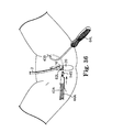
- FIGS. 34 through 38 are perspective views sequentially showing a surgical procedure in accordance with another aspect of the present invention, wherein:
- FIG. 34 shows a needle just passing an incision on the right side of a patient's body with the tip of the needle shown in dotted lines;
- FIG. 35 illustrates a needle just passing an incision on the left side of a patient's body with the tip of the needle and part of the surgeon's finger shown in dotted lines;
- FIG. 36 illustrates one side of a sling assembly and the needle of FIG. 35 as it emerges from the patient's vagina;
- FIG. 37 shows the sling assembly of FIG. 36 after it is attached to the needle of FIG. 36 ;
- FIG. 38 is a perspective view of a sling assembly being pulled through the body by a needle in accordance with the present invention.
- FIG. 39 is a perspective view of a design of a surgical instrument according to another aspect of the present invention.
- FIG. 40 is a top view of the instrument of FIG. 39 ;
- FIG. 41 is a bottom view of the instrument of FIG. 39 ;
- FIG. 42 is a front view of the instrument of FIG. 39 ;
- FIG. 43 is a rear view of the instrument of FIG. 39 ;
- FIG. 44 is a right end view of the instrument of FIG. 39 ;
- FIG. 45 is a left end view of the instrument of FIG. 39 ;
- FIG. 46 is a perspective view of a design of a instrument according to another aspect of the present invention.
- FIG. 47 is a top view of the instrument of FIG. 46 ;
- FIG. 48 is a bottom view of the instrument of FIG. 46 ;
- FIG. 49 is a front view of the instrument of FIG. 46 ;
- FIG. 50 is a rear view of the instrument of FIG. 46 ;
- FIG. 51 is a right end view of the instrument of FIG. 46 ;
- FIG. 52 is a left end view of the instrument of FIG. 46 ;
- FIG. 53 is a perspective view of a system for use in an inside out procedure according to the present invention that includes a portion that is at least partially reusable;
- FIG. 54 is a perspective view of a universal system capable of use in inside-out and outside in approaches according to the present invention, which system includes a needle having two regions capable of attachment to either a handle or a sling assembly;
- FIGS. 55-57 sequentially illustrate use of the system of FIG. 54 wherein:
- FIG. 55 illustrates passage of the needles using inside-out approaches
- FIG. 56 illustrates the needles after the handles have been removed, in preparation for attachment of a sling assembly on the regions of the needles previously occupied by the handles;
- FIG. 57 illustrates the system during implantation of the sling
- FIG. 58 is a schematic illustration of the system of FIG. 54 used in an inside-out approach (the right side of the patient) and an outside-in (the left side of the patient) approach;
- FIGS. 59-61 sequentially illustrate the system of FIG. 54 used in outside-in approaches wherein:
- FIG. 59 illustrates the needles inserted initially through the patient's skin and thereafter emerging from a vaginal incision
- FIG. 60 illustrates the system just prior to attachment of a sling assembly
- FIG. 61 illustrates the system of FIG. 54 during implantation of the sling
- FIG. 62 is a perspective view of another embodiment of surgical assembly according to the present invention, with a needle suitable for an outside-in approach (e.g. on the left side of the patient's body) and a sling assembly with a needle attached thereto suitable for an inside-out approach (e.g. through the right side of the patient's body);
- FIG. 63 is a perspective view of an alternative embodiment of sling assembly for use in accordance with the present invention.
- FIG. 64 is a perspective view of an alternative embodiment of sling assembly for use in accordance with the present invention, which assembly does not include a sheath;
- FIG. 65 is a perspective view of an alternative embodiment of sling assembly for use in accordance with the present invention.
- FIG. 66 is a top plan view of an alternative embodiment of sling assembly for use in accordance with the present invention.
- FIG. 67 is a top plan view of an alternative embodiment of sling assembly for use in accordance with the present invention.
- the present invention is directed to surgical instruments, assemblies and implantable articles for treating pelvic floor disorders such as incontinence or stress urinary incontinence (SUI) in both men and women.
- the present invention is also directed to improved surgical procedures that utilize the surgical articles.
- FIG. 1 is a side view of a sling assembly guide or needle 60 according to one aspect of the present invention.
- the needle 60 is preferably sized and shaped to be suitable for initial insertion through obturator fascia (see FIGS. 4 through 8 ).
- the needle 60 has a length sufficient to extend from the initial incision 400 adjacent the anterior side of the pubic bone, through the obturator foramen 3 (e.g. see FIG. 9 ) portion of the pubic bone to a position on the posterior side of the pubic bone, and to then emerge from a vaginal incision.
- FIG. 1 is a side view or a species of the present invention, the present invention is not limited to the particular shape disclosed. It is expressly understood that a large number of different sizes, shapes and dimensions of needles are suitable for the present invention.
- the needle 60 is preferably sized and shaped to pass through the obturator foramen 3 along a path that is substantially free of vascular and nerve structures.
- the size and shape of the needle 60 help avoid the sensitive structures.
- the path may be in a region between the superior pubic ramus and the inferior pubic ramus (see e.g. FIGS. 4 through 10 ).
- the tip of the needle is preferably substantially blunt to help avoid damage to the sensitive structures. Alternatively, the tip may be slightly sharpened to assist in the initial passage of the needle.
- the needle 60 comprises three substantial linear portions 60 A, 60 B and 60 C; each situated at an angle relative to the other linear portions. Preferably, the angles are different.
- the needle 60 preferably includes a leading portion 60 A, an intermediate portion 60 B and a trailing portion 60 C.
- the leading portion 60 A of the needle 60 is sized to extend through the initial incision 400 .
- the cross-sectional shape of the needle 60 is preferably substantially circular, but other cross sectional shapes such as, but not limited to, elliptical, polygonal, square and triangular are also contemplated herein.
- the diameter of the leading portion 60 A is less than 5 mm, more preferably less than 4 mm, and even more preferably less than 3.5 mm to avoid damaging or displacing tissue.
- the sudden angle between the intermediate portion 60 B of the needle and the leading portion 60 A helps the surgeon avoid sudden lurches of the needle after the region 58 passes through the obturator fascia, as the intermediate 60 B or trailing 60 C portions of the needle can be grasped or abut external portions of the patient to stop an undesirable, sudden lurch through tissue.
- the angle also helps the surgeon steer the needle 60 along a desired or predetermined path.
- the angle between the intermediate portion 60 B and the trailing portion 60 C is preferably greater than ninety degrees, more preferably, it is greater than one hundred and twenty degrees.
- the length of the trailing portion 60 C should be sufficient to allow the surgeon to leverage the end of region 58 of the needle and drive it along its predetermined, desired path. This geometry helps direct the end of the region 58 back toward the surgeon. This geometry also helps the surgeon pass the needle through this portion of the body and emerge from the vagina without undue tissue trauma.
- FIG. 3 illustrates a kit 15 according to an aspect of the present invention.
- the kit 15 preferably comprises an implantable material (e.g. a sling mesh provided as part of a sling assembly 46 ), at least one (preferably two) optional handle 64 , and at least one (preferably two) needle 60 .
- an implantable material e.g. a sling mesh provided as part of a sling assembly 46
- at least one (preferably two) optional handle 64 e.g. a sling mesh provided as part of a sling assembly 46
- at least one (preferably two) optional handle 64 e.g. a sling mesh provided as part of a sling assembly 46
- at least one (preferably two) optional handle 64 e.g. a sling mesh provided as part of a sling assembly 46
- at least one (preferably two) optional handle 64 e.g. a sling mesh provided as part of a sling assembly 46
- at least one (preferably two) optional handle 64
- the handle 64 is entirely optional.
- the handle may be removably attached to the needle, or it may be repositionably attached to the needle. Alternatively, the handle may be permanently attached to the needle 60 .
- FIGS. 13 and 14 illustrate an optional shape of handle 64 A suitable for permanent attachment to the needle 60 .
- Other suitable handles are disclosed, for example, in U.S. Provisional Patent Application Nos. 60/347,494; 60/336,884 and 60/343,658.
- the needle 60 is preferably made of a durable, biocompatable surgical instrument material such as, but not limited to, stainless steel (e.g. 316 stainless steel or 17-4 stainless steel), titanium, Nitinol, polymers, plastics and other materials, including combinations of materials.
- the needle 60 should have sufficient structural integrity to withstand the various forces (e.g. forces caused by dilator attachment, and penetration/passage of the needle 60 through the various tissues) without undergoing any significant structural deformation.
- the needles 60 could be sufficiently malleable to allow a practitioner or user of the device to modify the needle 60 to a desired shape and, thereby, optimize the procedural approach.
- Needles 60 may be disposable or reusable (e.g. sterilizable by steam sterilization procedures).
- the needles 60 may be provided in a kit, such as any of the kits described in any of published U.S. patent application Ser. Nos. 2002-0151762-A1; 2002-0147382-A1; 2002-0107430-A1, -2002-0099258-A1 and -2002-0099259-A1; and U.S. Provisional Application Ser. Nos. 60/263,472, filed Jan. 23, 2001; 60/269,829, filed Feb. 20, 2001; 60/281,350, filed Apr. 4, 2001; 60/295,068, filed Jun. 1, 2001; 60/306,915, filed Jul. 20, 2001, and U.S. Provisional Patent Application No. 60/332,330, filed Nov. 20, 2001.
- kit includes the needle 60 and other needles (not shown, but for example including the needles shown in published U.S. patent application Ser. No. -2002-0099258-A1) designed for placing a sling from the abdominal rectus fascia, under the urethra, and then back to the rectus fascia. If a traditional pubovaginal sling procedure seems to be an option for a patient but, during or prior to the surgical procedure, it becomes apparent that excessive scar tissue (e.g. due to a previous surgery) exists and would render the traditional procedure less desirable or impossible, then the needle 60 may be used in an alternative approach. Since the needles 60 are also provided in a kit, the surgeon has the option of conducting an alternative surgical procedure with the needles 60 .
- a needle may optionally include the capacity to deliver a medicament (e.g. anesthesia) during the surgical procedure.
- a medicament e.g. anesthesia
- the needle 60 may be hollow with an open end.
- the needle may have a connector for associating with a medicament reservoir and delivery mechanism (e.g. a syringe).
- the present invention may be utilized in conjunction with a wide variety of sling materials and sling assemblies.
- the sling may be integral, monolithic, or a composite of different components or segments of different components.
- Suitable non-synthetic materials include allografts, homografts, heterografts, autologous tissues, cadaveric fascia, autodermal grafts, dermal collagen grafts, autofascial heterografts, whole skin grafts, porcine dermal collagen, lyophilized aortic homografts, preserved dural homografts, bovine pericardium and fascia lata.
- Suitable synthetic materials for a sling include polymerics, metals and plastics and any combination of such materials.
- non-absorbable materials include MarlexTM (polypropylene) available from Bard of Covington, R.I., ProleneTM (polypropylene) and Mersilene (polyethylene terphthalate) Hernia Mesh available from Ethicon, of New Jersey, Gore-TexTM (expanded polytetrafluoroethylene) available from W. L. Gore and associates, Phoenix, Ariz., and the polypropylene sling available in the SPARCTM sling system, available from American Medical Systems, Inc. of Minnetonka, Minn.
- absorbable materials include DexonTM (polyglycolic acid) available from Davis and Geck of Danbury, Conn., and VicrylTM available from Ethicon.
- suitable materials include those disclosed in U.S. patent application Ser. No. 2002/0072694.
- More specific examples of synthetic sling materials include, but are not limited to polypropylene, cellulose, polyvinyl, silicone, polytetrafluoroethylene, polygalactin, Silastic, carbon-fiber, polyethylene, nylon, polyester (e.g. dacron) PLLA and PGA.
- the sling material may be resorbable, absorbable or non-absorbable. Optionally, some portions may be absorbable and other portions may be non-absorbable.
- the synthetic slings may be knitted, woven, sprayed or punched from a blank. Some slings may be sufficiently robust to be inserted without a protective sleeve. In other embodiments, some synthetic slings may have an associated protective sleeve (described in greater detail below) to assist with the implantation.
- the sling may comprise a mesh material.
- the mesh material comprises one or more woven, knitted or inter-linked filaments or fibers that form multiple fiber junctions throughout the mesh.
- the fiber junctions may be formed via weaving, knitting, braiding, bonding, ultrasonic welding or other junction forming techniques, including combinations thereof.
- the size of the resultant openings or pores of the mesh may be sufficient to allow tissue in-growth and fixation within surrounding tissue.
- the holes may comprise polygonal shaped holes with diagonals of 0.132 inches and 0.076 inches.
- the quantity and type of fiber junctions, fiber weave, pattern, and material type influence various sling properties or characteristics.
- the mesh may be woven polypropylene monofilament, knitted with a warp tricot.
- the stitch count may be 27.5 courses/inch (+ or ⁇ 2 courses) and 13 wales/inch (+ or ⁇ 2 wales).
- the thickness of this example is 0.024 inches.
- This embodiment of sling is preferably associated with a protective sleeve (described in greater detail below). Non-mesh sling configurations are also included within the scope of the invention.
- the sling mesh 42 A is preferably elastic, as opposed to the substantially inelastic mesh available in Europe as Uratape® from Porges, and the tape described in Published U.S. patent application Ser. No. 2002/0099260.
- a mesh may be tested to determine whether it is elastic using a series IX Automated Materials Testing System (an Instron), available from Instron Corporation. A 1 cm wide sample of the mesh may be placed in the Instron with a crosshead speed set at 5 in/min and a gauge length of 1 inch.
- An elastic mesh exhibits at least a 7% elongation under a 1 ⁇ 2 pound load, more preferably about a 10% elongation under a 1 ⁇ 2 pound load, and more preferably about 14% under the 1 ⁇ 2 pound load.
- An inelastic mesh exhibits less than an 7% elongation under a 1 ⁇ 2 pound load.
- the mid-portion of the sling mesh (the portion designed to reside underneath the midurethra) is preferably substantially free of any silicone coatings.
- the mid-portion of the sling may comprise a non-synthetic material, constructed according to the teachings of U.S. Provisional Patent Appl. No. 60/405,139, filed Aug. 22, 2002.
- Other suitable synthetic slings are described in published U.S. Pat. No. 2002-0138025-A1, published Sep. 26, 2002.
- the sling material may have one or more substances associated therewith through a process such as coating or they may be incorporated into the raw material of the sling.
- appropriate substances include, without limitation, drugs, hormones, antibiotics, antimicrobial substances, dyes, silicone elastomers, polyurethanes, radiopaque filaments or substances, anti-bacterial substances, chemicals or agents, including any combinations thereof.
- the substances may be used to enhance treatment effects, reduce potential sling rejection by the body, reduce the chances of tissue erosion, enhance visualization, indicate proper sling orientation, resist infection or other effects.
- the slings are preferably rectangular for treating SUI in females, other shapes are also contemplated.
- the slings may be any of a wide variety of shapes.
- the sling may be of the general shape of the slings described and shown in Moir et al., The Gauze - Hammock Operation , Journal of Obstetrics and Gynaecology of the British Commonwealth, Volume 75, No. 1, Pps. 1-9 (1968).
- FIG. 12 shows a sling 90 with a shape other than a purely rectangular shape.
- This embodiment of sling 90 includes a mid portion that is wider than the remaining portions of the sling 90 .
- the mid portion is preferably placed under the urethra 16 , along the mid portion of the urethra.
- FIG. 2 illustrates a sling assembly 46 comprising sling 42 and sheath 44 .
- the overall dimensions of the sling assembly 46 are sufficient to extend from a superficial incision 400 near the obturator fascia (see FIGS. 4 through 8 ), to an undersurface of the urethra 16 and back to another incision 400 in obturator fascia that is opposite the first incision.
- the size of the sling can take into account the imprecision associated with the range of human anatomy sizes.
- the sheath length of the assembly of the present invention is approximately within the range of 10 cm to 50 cm, sheath width is approximately within the range of 1.0 cm to 2 cm, and sheath material thickness is approximately within the range of 0.127 mm to 0.203 mm, respectively.
- the associated sling 42 has a length, width and thickness approximately within the range of 7 cm to 50 cm; 1.0 cm to 2 cm; and 0.508 mm to 0.711 mm, respectively.
- the sling 42 of the present invention can be implanted without the need for bone screws.
- the precise, final location of the sling 42 will depend on a variety of factors including the particular surgical procedure(s) performed, and any preconditions of the patient such as scar tissue or previous surgeries.
- the sling may be placed near the bladder neck.
- the sling 42 has a tensioning filament or suture T as disclosed, for example, in U.S. Published patent application Ser. No.-2002-0107430-A1.
- the tensioning suture T may be constructed from a permanent or absorbable material.
- the sling 42 comprises a substantially elastic, polypropylene sling such as a sling constructed from the polypropylene sling material available in the SPARC Sling System, available from American Medical Systems of Minnetonka, Minn.
- FIG. 30 illustrates an embodiment with the tensioning filament T extending along end portions, but not extending along a mid-portion of the sling.
- the sling 42 A comprises a polypropylene sling mesh 42 A. It is constructed of polypropylene monofilament that is precut to about 1.1 cm width ⁇ 35 cm length.
- the tensioning filaments T in this embodiment are fixed at each end to the sling material (e.g. a polypropylene mesh) by welding (e.g. ultrasonic), knotting, anchoring, adhering (e.g. with and adhesive) or the like.
- Absorbable tensioning sutures T are threaded into the length of the sling mesh 42 A from each end to allow for tensioning adjustment of the sling mesh 42 A after placement in the patient is achieved.
- the mid portion of the sling mesh 42 A is preferably free of the tensioning sutures T. For example, approximately 5 mm may separate the ends of the two tensioning sutures T.
- Two plastic sheaths 44 A that overlap in the center of the sling mesh cover the sling mesh and protect it during placement.
- the plastic covering over the mesh is designed to minimize the risk of contamination.
- a protective sheath 44 is preferred, especially when the sling 42 is elastic.
- a sheath is particularly desirable when the sling is elastic as the sheath 44 assists in introduction of the sling within tissue and avoids damage to the elastic sling material.
- the sheath 44 is used during insertion of a synthetic sling 42 . After the sling 42 is implanted, the sheath 44 is removed and discarded.
- the protective sheath 44 is constructed of a material that affords visual examination of the implantable sling material 42 and that affords convenient passage of the assembly 46 through tissue of the patient.
- the sheath 44 is made of polyethylene. Other materials including, without limitation, polypropylene, nylon, polyester or Teflon may also be used to construct the sheath 44 .
- the sheath 44 should also conveniently separate from the sling material 42 after the sling 42 is implanted without materially changing the position of the sling 42 .
- the sheath 44 may comprise two elongate, separable sections.
- portions of the sheath 44 may detachably and telescopically overlap near the middle portion of the sling or it may be slit (e.g. longitudinally or perpendicular to the longitudinal axis) to afford convenient separation.
- the present invention comprises a dilator 54 ( FIG. 2 ) for use in a surgical sling procedure.
- the dilator is optional according to some aspects of the present invention as, for example, the sling and/or protective sheath may be directly connected to a novel needle of the present invention by virtue of an eyelet in the needle or other arrangements disclosed in greater detail below.
- the dilator 54 comprises a body portion having first end portion 56 and second end portion 52 opposite the first end portion 56 .
- the first end portion 56 has surfaces for associating the dilator with a needle (e.g. region 58 of needle 60 ).
- the second end portion 52 has sling association means for associating the article with a sling, sling assembly or component thereof.
- the sling association means may comprise a hole 90 .
- the dilator 54 comprises a short article that dilates a needle track for ease of sling introduction and positioning within the patient.
- Region 58 of the needle 60 is preferably keyed to allow for convenient, secure attachment of the needle 60 relative to the dilator 54 .
- the attachment is permanent.
- the kit shown in FIG. 3 includes two dilators 54 .
- the dilators 54 atraumatically create and/or expand the passageway through the tissues for sling assembly delivery.
- the dilator 54 is preferably short relative to a needle 60 for ease of passage of the assembly and to reduce the overall amount of tissue that is deflected at one time.
- the dilator is less than 2.5 inches in length, and more preferably, it is less than one inch in length, even more preferably, it is less than 0.7 inches in length.
- the maximum radius of a dilator 54 is preferably less than 10 mm, more preferably less than 7.5 mm, even more preferably less than about 5 mm.
- the tip or leading end of the dilator 54 is preferably blunt, as, in preferred embodiments, the leading tip of the dilator 54 will pass through tissue that has already been pierced by a needle 60 .
- the dilator 54 may be made from a variety of biocompatible and sterilizable materials including, without limitation, acetal, polycarbonate, polypropylene, Delrin®, Acrylonitrile-Butadiene-Styrene (ABS), polyethylene, nylon and any combination of biocompatible materials.
- the dilator 54 preferably includes means for associating with a surgical needle 60 .
- the association means affords a permanent affixation between the dilator 54 and the needle 60 .
- permanent affixation it is meant that it would be very difficult to manually separate the dilator from the needle after they have become permanently affixed.
- the surgeon cuts an end of the sling 42 as described more fully below.
- the association means preferably affords quick and convenient attachment of the dilator 54 to the needle 60 to avoid wasting time in the midst of a surgical procedure. The attachment should also be secure to avoid separation of the needle 60 and dilator 54 while the combination is passed through tissue.
- the means comprises a shoulder surface on the needle and complementary slot surfaces on the dilator 54 .
- the dilator 54 may be approximately 3.1 cm (1.2 inches) in length.
- the dilator 54 preferably includes a gentle taper near its first end 56 .
- the dilator is sized and shaped to provide atraumatic passage through body tissue.
- the taper and relatively smooth outer surface of the dilator 54 facilitate atraumatic passage of the dilator 54 and attached sling assembly 46 through the various tissues of the patient.
- the presence of the dilator 54 allows a gentle transition between the diameter of the needle, to the shape of the dilator, and finally to the sling assembly 46 .
- the attachment of the dilator 54 to the needle 60 is a substantially linear fashion, as opposed to a twisting or screw-like attachment.
- the attachment is a snap-fit attachment to save time during the surgical procedure.
- the second end 52 of the dilator 54 associates the dilator with one end of a sling 42 , or sheath 44 or sling assembly 46 .
- the sheath 44 or sling 42 is preferably attached to the dilator 54 via a first opening or through-hole located near the second end 52 of the dilator 54 .
- the opening operates as a universal sling material or assembly attachment point which can receive a variety of materials, such as fascia, autologous materials, synthetics, biologic tissues and any other similar tissues, including any combinations.
- the end portion 48 or 50 of one end of the sheath 44 is threaded through the opening of the dilator 54 and secured to the sheath 44 , thereby forming a loop.
- ends 48 or 50 may be fastened onto the sheath 44 via ultrasonic welding, bonding, melting, suturing, sealing or other attachment techniques.
- the end 52 of the dilator 54 preferably includes a cut-away section to provide room to receive sling assembly material to reduce the overall profile of the sling assembly experienced by tissue during sling passage. Therefore, when the sheath is attached to the cut-away section, the additional sheath material is not apt to significantly increase the relative thickness, diameter or profile of the dilator 54 .
- the dilator 54 is preferably preattached to the sling assembly 46 .
- the sling 42 itself may be attached to the dilator, e.g. with a suture threaded through the opening of the dilator and tied to the sling.
- One or more longitudinal slots located on the outer surface of the dilator 54 allow the wall of the dilator 54 to expand in a radially outward direction when the first end of the needle 60 is inserted into the opening of the dilator 54 .
- a shoulder of the dilator 54 passes the recess of the needle 60
- the wall of the dilator 54 collapses around the needle 60 as the shoulder seats into the recess, thereby securing the dilator 54 on the needle 60 and blocking separation of the dilator 54 and needle 60 .
- a portion of the dilator 54 includes a taper having a decreasing profile toward the second end 56 of the dilator 54 .
- the taper preferably gently cams tissue out of the path of the sling assembly 46 as the sling assembly is inserted in the body.
- the taper is also sized and shaped to reduce the amount of friction or resistance as the device is drawn through the tissues of the patient. The amount of force required to manipulate the device through the tissues is thereby reduced. This in turn provides the user of the assembly with additional control over device insertion and maneuverability through tissue and within the patient.
- other dilator profiles such as conical, flared, frusto-conical, pyramid-shaped, elliptical or other applicable profiles may also be used.
- a surgical kit according to the present invention may optionally include additional accessories.
- a surgical drape specifically designed for urological procedures such as a sling procedure may be included in a kit of the present invention.
- a drape is disclosed in published U.S. patent application Ser. No. 2002-078964-A1.
- an article for objectively setting tension of the sling such as one of the articles described in U.S. patent application Ser. No. 09/968,239, filed Oct. 1, 2001 may be included in the kit.
- kits according to the present invention preferably include at least two needles.
- the needles may be substantially identical, in other instances, they may be different.
- Two or more needles reduce the need to reuse a non-sterile needle at a different location with a patient, thereby eliminating cross contamination issues.
- Additional needles, handles, dilators and other elements may also be included for surgical convenience, for avoidance of contamination from one portion of the body to another, for ease of manufacturing or sterilization or for surgical requirements.
- two different types of needles may be included in a kit.
- One type of needle may be suitable for an outside-in (e.g. from the skin incision toward a vaginal incision) approach.
- Another type may be suitable for an inside-out (e.g.
- a universal needle e.g. one suitable for both an inside out and an outside in approach
- FIG. 53 illustrates a system 101 for use in an inside-out procedure.
- the system 101 comprises a pair of needles 109 that are sized and shaped for the inside-out approach.
- the system 101 also includes a sling assembly comprising a sling 111 , and protective sheath 113 .
- the sling assembly may be permanently attached to the needles 109 at regions 117 .
- the needle 109 can include specially shaped structure (e.g. an eyelet) in region 117 that affords association between the needle 109 and sling or sling assembly after passage of the needle 109 .
- the system 101 may optionally include releasable handle portions 119 that can be releasably attached to the needles 109 at ends 121 .
- FIG. 54 illustrates a system 102 for use in either an inside-out procedure or an outside-in procedure.
- the system 102 comprises a sling assembly 146 having a sling material 142 , a sheath 144 and dilators 154 .
- the system includes a handle portion 164 that is at least partially reusable.
- Needles 162 are suitable for either an inside-out or outside in procedure.
- the regions 158 of the needles 162 may be attachable to either a dilator 154 or the handle portion 164 .
- the needles may be attachable to the implantable material itself or a sling and protective sleeve assembly without any dilator.
- the system 102 allows the needles to be passed through tissue without requiring that they be attached to a sling or sling assembly. Thus, if the initial passage is not deemed to be optimum, the needles may be repassed without subjecting the sling or sling assembly to damage during the initial passage.
- FIGS. 55-57 sequentially illustrate use of the system 102 using an inside-out approach.
- FIG. 55 illustrates passage of the needles 162 using inside-out approaches.
- the handles 164 are optional. If they are used, they are removed once the needles 162 have emerged from the skin incision.
- FIG. 56 illustrates the needles 162 after the handles 164 have been removed, in preparation for attachment of a sling assembly 146 on the regions 158 of the needles 162 previously occupied by the handles 164 .
- FIG. 57 illustrates the system 102 during implantation of the sling.
- FIG. 58 is a schematic illustration of the system 102 used in an inside-out approach (the right side of the patient) and an outside-in (the left side of the patient) approach.
- This combination may be utilized, by a right-handed surgeon who prefers to pass the leading edge of the needle with his or her dominant hand. Alternatively, the combination may be reversed for a left-handed surgeon.
- the remainder of the surgical procedure may be substantially identical to that depicted in FIGS. 56 and 57 .
- the handle 164 utilized on the right side of the patient's body may optionally be placed on the other side of the needle after it emerges from the patient's body to conveniently assist the surgeon in moving the needle 162 and sling assembly 146 through the tissue.
- FIGS. 59-61 sequentially illustrate the system 102 used in outside-in approaches.
- FIG. 59 illustrates the needles 162 inserted initially through the patient's skin and thereafter emerging from a vaginal incision.
- FIG. 60 illustrates the system 102 just prior to attachment of a sling assembly 146 .
- FIG. 61 illustrates the system 102 during implantation of the sling.
- the system 200 comprises a needle 262 suitable for an outside-in approach on the left side of the patient's body and associated handle 264 .
- the system 200 also includes a sling assembly 246 comprising a sling 242 , protective sheath 244 and dilator 254 at one region.
- the dilator 254 is designed to mate with the region 258 of the needle 262 .
- a needle 265 may be permanently attached to the sling assembly 246 .
- the needle 265 is sized and shaped to be suitable for an inside-out approach on the right side of a patient's body.
- the needle 265 includes a leading region 266 suitable for that purpose.
- the leading region 206 may include a portion that is blunt or, alternatively somewhat sharpened.
- the system 200 is particularly suitable for a surgeon that desires to initially pass needles with his or her dominant hand.
- the depicted system 200 is suitable for a right-handed surgeon.
- a mirror image or reverse system is particularly suitable for a left handed surgeon that desires to initially pass a needle with his or her left hand.
- the system 200 could include a detachable handle for the needle 265 to assist in passage of the needle 265 .
- the needle 264 may be omitted from the system.
- the needle 265 may be used to pass the sling initially using an outside-in approach on one side of the body and then continuing to insert the sling using an inside out approach on the other side of the body.
- a kit comprises two surgical instruments such as those shown in FIGS. 15-22 , and a polypropylene sling mesh assembly with attached dilators as shown in FIG. 28 .
- Such a kit may be provided for the placement of a pubourethral sling for the treatment of female stress urinary incontinence (SUI) resulting from urethral hypermobility and/or intrinsic sphincter deficiency.
- SUPI female stress urinary incontinence
- a dilator used for associating the sling with the surgical instrument is shown in FIG. 23 A.
- Dilator 54 is shown having a diameter X that is substantially the same as the diameter x of the needle 60 .
- the system can avoid subjecting tissue to a sudden discontinuity as it moves through tissue. This low profile can assist in effectively and efficiently implanting the sling material.
- the dilator is shown having a diameter that matches the diameter of the needle at one end thereof, and gets larger towards the other end.
- FIG. 23C another low profile dialator and needle combination is shown.
- any flats on the needle and on the mating surfaces within the connector have been removed.
- the removal of any flats allows the needle and connector to be quickly and easily connected without worrying about proper orientation of the connector relative to the needle.
- This embodiment also allows the connector to rotate during passage within the body and thus may decrease the resistance of the passage of the needle once the connector has been attached to the needle end.
- the needle end is recessed and the connector's leading edge may be hidden in this recess rather than extending beyond the diameter of the needle. This embodiment avoids any exposed edge or lip at the interface of the connector and needle.
- the smaller profile further provides less dilation by the connector during withdrawal and reduces the resistance to withdrawal of the needle once the connector has been attached.
- the smaller connector creates a smaller opening the body during passage which may aid in the anchoring of the sling into the area of deployment.
- the smaller channel that the sling is placed in may provide greater anchoring forces on the sling immediately after deployment and before ingrowth.
- the overall amount of the connector that extends beyond the tip of the needle and the overall length of the connector is shortened in this embodiment. Because the connector is relatively straight, any amount that the connector extends beyond the tip of the needle may actually increase the resistance during withdrawal and may actually result in more trauma and dilation to the tissue than may be desired.
- kits of the present invention may be packaged together, separately or in subassemblies depending on a variety of factors such as shelf life and sterilization requirements. They may be assembled at the manufacturing location or at the healthcare location. Any suitable sterilization procedure may be utilized to sterilize the contents of a kit. Suitable sterilization techniques include, but are not limited to steam, ethylene oxide, electron beam, vapor (e.g. hydrogen peroxide or peracetic acid), gamma or plasma procedures.
- the surgical instrument may be reusable or single use devices.
- FIG. 11 shows another embodiment of the present invention.
- the Figure is schematic and is not to scale. Some features are exaggerated or omitted to illustrate or emphasize other details.
- the vaginal incision is only shown schematically and should not be interpreted as identifying a preferred size, shape or location of the incision.
- the needle 60 acts as a surgical guide needle (e.g. with a diameter of about 4 mm, or less, preferably about 3 mm) for a relatively larger sling transport needle 604 (e.g. with a diameter of about 5 mm or less).
- the sling transport member has a sling assembly 610 (e.g. a sling mesh and insertion sheath) attached thereto.
- the sling transport needle 604 may have a more exaggerated hook shape, similar to the shape shown in PCT WO 02/39890.
- the guide needle 60 serves a different purpose than the surgical transport needle 604 .
- the surgical guide needle 60 is preferably small and has a blunt tip.
- the blunt tip is initially inserted through incision 400 adjacent obturator fascia and then through a vaginal incision. Inserting a small, blunt needle in this fashion provides the surgeon with additional control in maneuvering through the anatomy of a patent and in avoiding sensitive tissue.
- a surgical kit may include a dilator 54 for placement on a tip of needle 60 .
- the sling transport needle 604 may optionally include a sharp tip.
- the dilator 54 receives the tip of the needle 604 .
- a technique of pushing sideways on the sling transport needle 604 with one hand while steering the tip of the needle 604 by holding guide needle 60 with the other hand may be used to implant the sling.
- the dilator 54 may include surfaces for firmly engaging and attaching to needle 604 .
- Those surfaces can include mechanical interlocking structures, grasping structures or interlocking structures.
- the needle 60 need not have specially shaped surfaces 58 for engaging the dilator and can instead have cylindrical surfaces adapted to be received within the dilator.
- a novel needle 60 R according to the present invention.
- the needle 60 R is particularly suitable for passage on the right side of a patient's body, initially from an incision in the region of the patient's obturator foramen and subsequently emerging through a vaginal incision.
- the needle 60 R includes a handle 64 R and a leading region 62 R.
- the leading region 62 R includes a substantially blunt distal tip 63 R and specially designed surfaces 67 R and 65 R suitable for mating with complementary surfaces on a dilator or connector (described in more detail below).
- a novel needle of the present invention may utilize an eyelet in the distal region to afford a suture attachment to a sling or sling assembly without the use of a dilator.
- the needle 60 R has substantial structure in three dimensions, as opposed to, for example, the substantially flat needle shown in FIG. 1 (or an Emmet needle) that only includes substantial structure in two dimensions. Having substantial structure in three dimensions helps the surgeon pass the needle through the obturator foramen and subsequently through a vaginal incision by affording greater surgeon control.
- the handle of the needle allows the surgeon to move the distal end of the needle with an ergonomic wrist roll action
- FIGS. 15A , 16 A, 17 A and 18 A show another embodiment of novel needle 60 R′ that is similar, but not identical to the needle 60 R.
- the needle 60 R′ is also particularly suitable for passage on the right side of a patient's body, initially from an incision in the region of the patient's obturator foramen and subsequently emerging through a vaginal incision.
- FIGS. 19 , 20 , 21 and 22 show another novel needle 60 L according to the present invention.
- the needle 60 L is particularly suitable for passage on the left side of a patient's body, initially from an incision in the region of the patient's obturator foramen and subsequently emerging through a vaginal incision.
- the needle 60 L includes a handle portion 64 L and a leading region 62 L.
- the needle 60 R includes substantial structure in three dimensions.
- FIGS. 19A , 20 A, 21 A and 22 A show another embodiment of novel needle 60 L′ that is similar, but not identical to the needle 60 L.
- the needle 60 L′ is also particularly suitable for passage on the left side of a patient's body, initially from an incision in the region of the patient's obturator foramen and subsequently emerging through a vaginal incision.
- the instruments in FIGS. 15-22 are shown with indicator marks 66 , 68 and 70 .
- the indicator marks may be used by the surgeon to determine how far the need has been advanced into the patient.
- the indicator marks may, as examples, be mechanically or laser etched into the needle portion of the instruments. Marks may be placed at even spacings (e.g. every millimeter) to provide a visual measure of the distance the needle has been advanced. As an alternative, different regions of the needle may be color coded to provide a further visual indication to the surgeon of how far the needle has advanced into the patient.
- novel needle 64 L′′ is substantially similar to the needle 64 L′, except that the tip T of the needle lies substantially in the plane P of the handle H of the needle 64 L′′. It is believed that such an arrangement of the elements may assist some surgeons in conjuring a mental image of the location of the tip T of the needle 64 L′′ relative to the body while the needle is being passed through a patient outside the surgeon's direct vision. The arrangement of the tip and the handle affords visual feedback concerning the approximate location of the tip of the needle when the tip is not under direct vision.
- this needle 64 L′′ includes an eyelet E for threading a suture so that the needle 64 L′′ can be tied to an implantable material or assembly such as a knitted polypropylene sling with an associated sheath.
- the handle of the instrument has been marked with an indicator 72 to provide a visual indication for the surgeon of the rotational location of the tip 62 of the needle.
- the visual indication is the letter T on the side of the handle on which the needle ends.
- FIGS. 63 through 67 show various embodiments of sling assemblies suitable for use in the present invention. These assemblies may be used in systems that do not include a dilator.
- FIG. 63 illustrates a sling assembly 300 having sutures 306 for threading through an eyelet of a needle to associate the assembly 300 with a needle.
- the assembly 300 may comprise a composite assembly with synthetic portions 308 and a non-synthetic mid portion 309 connected with fasteners 303 .
- FIG. 64 shows a sling assembly 320 comprising only a synthetic mesh material 322 .
- Sutures 6 may be threaded through an eyelet of a needle to associate the assembly 320 with a needle.
- a sheath may be added to the assembly 320 , especially when the mesh 322 is elastic.
- FIG. 65 illustrates a sling assembly 330 comprising a non-synthetic sling 332 .
- Sutures 336 may be threaded through an eyelet of a needle to associate the assembly 330 with a needle.
- suture anchors or pledgets may be utilized to avoid suture pull through.
- FIG. 66 illustrates a sling assembly 340 comprising a sling mesh 342 and a sheath 344 .
- the ends of the sling mesh 342 may be attached to the ends of the sheath 340 by welding, suturing, or other suitable means.
- Sutures 346 may be tied about the ends of the sheath 344 to form a dilator-like structure for pushing tissue out of the way of the assembly 340 during implantation.
- the sutures 346 may be threaded through an eyelet of a needle to associate the assembly 340 with a needle.
- FIG. 66 also shows a tensioning suture, but this is optional and can be omitted.
- FIG. 67 illustrates another sling assembly 350 comprising a synthetic mesh 352 and a sheath 354 .
- Sutures 356 may be threaded through an eyelet of a needle to associate the sling 352 with a needle.
- Sutures 358 may be tied about the ends of the sheath 354 to form a dilator-like structure for pushing tissue out of the way of the assembly 350 during implantation.
- FIG. 67 also shows a tensioning suture T′, but this is optional and can be omitted.
- the handles of the surgical instruments shown in FIGS. 15-20B includes indicia indicating the proper side of the patient.
- the indicia may be any suitable information conveying word, symbol or depiction.
- the indicia may simply be “right” or “left.”
- the indicia may include a drawing similar to FIG. 32 .
- the indicia may include a drawing similar to FIG. 33 .
- the various embodiment of three dimensional needles described above preferably include a substantially straight spacer portion emerging from an end of the handle portion preferably along the handle axis. This helps afford convenient passage of the needle using an ergonomic wrist roll adopted by some surgeons.
- the three dimensional needles also include a structure that can be described as a variable spiral portion extending from the distal end of the straight spacer portion. As shown, the spiral portion is preferably variable as the angle of the spiral portion changes between the end of the extension portion and the distal end of the needle. The shape of the spiral portions help avoid over insertion of the needle into the body which helps avoid damage to the sensitive structures in this region of the body.
- the variable spiral portions of the three dimensional needles have tissue clearance depth TCD of greater than about 0.5 inches and less than about 2.5 inches, more preferably the tissue clearance depth is between 0.75 inches and about 2.25 inches, more preferably it is between about 1.5 and 2 inches, and even more preferably it is about 2 inches.
- the tissue clearance depth TCD is the distance between the end of the extension portion and a point along an extension of the axis of the straight spacer portion which is defined by a line that is normal to the axis and that intersects the distal tip of the needle.
- the tissue clearance depth TCD helps space the distal tip of the needle from the distal end of the extension portion to reduce interference in needle passage by the distal end of the extension portion.
- variable spiral portions of the three dimensional needles have a maximum width MW that is preferably great enough to afford passage around the inferior pubic ramus and through the natural opening of the pubic bone, but small enough to avoid sensitive structure in this region of the body.
- the maximum width MW is greater than about 1.25 inches and less than about 3 inches, more preferably, it is between about 2 and about 2.225 inches and more preferably, it is about 2.15 inches.
- the dilator 54 S includes a hole 90 S for receiving a sling or a sheath or both in order to associate the dilator with a sheath.
- a shorter dilator is preferred to reduce tissue trauma and afford convenient, easy passage.
- Rotation of a helical needle can cause a substantially straight dilator to skid or plow through tissue instead of moving in a direction parallel to the longitudinal axis of the dilator.
- a shorter dilator will reduce tissue trauma associated with such plowing or skidding.
- a slightly curved or arcuate dilator may be used to reduce plowing or skidding.
- the length L of a substantially straight dilator 54 S is substantially short, preferably less than about 30 mm (1.2 inches) more preferably less than about 18 mm, 0.7 inches.
- the outermost diameter D of the dilator 54 S is preferably less than about 6 mm 0.24 inches, more preferably less than about 5 mm, even more preferably, less than about 4 mm.
- the dilator 54 S preferably has surfaces 51 S that provide a smooth transition between the needle (e.g. 60 L) and the sling assembly.
- the angle theta is preferably less than about 15 degrees and more preferably less than about 12 degrees.
- one substantially straight dilator 54 S may be used with either a left or a right side needle.
- a combination includes a distal region of the needle that is substantially straight.
- This length (e.g. L′′ in FIG. 26A ) is preferably short, preferably less than 0.9 inches, more preferably less than 0.8 inches, more preferably about 0.42 inches.
- the length L′ in FIG. 25 may be 0.3 inches.
- the dilator is preferably capable of being “permanently affixed” to the needle.
- the needle is attached to the dilator without a suture.
- FIG. 26A illustrates one example of a permanently affixed needle and sling assembly.
- permanent affixation it is meant that it would be very difficult to manually separate the dilator from the needle after they have become permanently affixed.
- a cut is made through the mesh and protective sleeve) to separate the mesh from the needle/dilator subassembly.
- the connection between the needle and dilator preferably affords quick and convenient attachment of the dilator to the needle to avoid wasting time in the midst of a surgical procedure.
- the attachment should also be secure to avoid separation of the needle and dilator while the combination is passed through tissue.
- the dilator 54 S includes an internal stop surface 57 S that is complementary with specially shaped surfaces on a needle (e.g. 62 R, FIG. 27 ). As best seen in FIG. 26A , the stop surface 57 S is designed to engage complementary shoulder surface (e.g. 65 R, FIG. 27 ) to achieve the desired convenient, but permanent affixation.
- a needle e.g. 62 R, FIG. 27
- complementary shoulder surface e.g. 65 R, FIG. 27
- the needle is attached to the dilator without any screw-type connector.
- the connection is a snap-fit, quick connection for secure, convenient use by the surgeon.
- the connection is a press on connection that does not require substantial rotation of elements (especially elements that are within the body) as such a connection is less likely to displace a needle or otherwise injure the patient.
- the dilators 54 S may form a portion of a sling assembly that includes synthetic sling end portions 42 A′, sheaths 44 A′ covering at least some of the sling end portions 42 A′ and a non-synthetic mid-portion 45 ′.
- a composite sling assembly may be assembled by the surgeon or provided preassembled using the teachings or components of published U.S. patent application Ser. Nos. 2002-0147382-A1 or 2002-0082619-A1, or U.S. patent application Ser. No. 10/335,119, filed Dec. 31, 2002.
- the present invention comprises the ornamental design for a surgical instrument, as shown in FIGS. 39 through 45 and described in the Brief Description of the Drawings.
- the present invention comprises the ornamental design for a surgical instrument, as shown in FIGS. 46 through 52 and described in the Brief Description of the Drawings.
- FIGS. 39-52 The broken line showing in FIGS. 39-52 are for illustrative purposes only and form no part of the claimed design.
- the above-described surgical instruments may be disposable or reusable.
- portions of the surgical instrument may be reusable (sterilizable) and other components may be disposable.
- the present invention utilizes an obturator passage of the needle, preferably in a direction from the anterior to the posterior side of the pubic bone.
- An obturator approach affords a sling procedure where previous scarring in the region of the retropubic space or other anatomical features would prevent or restrict a traditional pubovaginal sling procedure.
- An obturator approach is also likely to avoid bladder perforations, a possible but rare complication with some prior art pubovaginal procedures. It may also be more convenient to conduct a concomitant repair (e.g. cystocele repair) with a sling inserted with a side approach as the sling is placed in a more horizontal position (e.g. see FIGS. 9 and 10 ) than the U-shaped sling procedures of the prior art.
- a concomitant repair e.g. cystocele repair
- a catheter 2 e.g. Foley
- a small incision e.g. a transverse incision
- the amount of dissection may vary according to surgeon preference.
- dissection is sufficient to allow the surgeon's finger to meet the end of the region 58 of the needle 60 just after it passes through the obturator fascia.
- Two small stab incisions 400 are also made near the obturator fascia to afford needle entry.
- the precise location of the stab incisions 400 may vary according to surgeon preference. For example, some surgeons may place the incision adjacent the obturator opening of the pubic bone. Other surgeons may slightly offset the incision in order to use the bias provided by the patient's tissue to urge the tip of the needle in a direction toward the posterior surface of the pubic bone.
- the end of region 58 of needle 60 is shown just passing an incision 400 on the patient's right side.
- the surgeon's finger is initially placed in the vaginal incision sufficient to meet the end of region 58 of the needle 60 after it passes through the obturator fascia and the obturator foramen 3 (see FIG. 9 ).
- a path for the needle 60 through the obturator foramen 3 that is substantially free of vascular and nerve passages is selected.
- the surgeon preferably initially identifies the anatomical structures of the pelvis such as the ischial tuberosity and obturator foramen 3 by palpation of the tissue.
- FIG. 5 shows the end of region 58 of needle 60 just passing an incision 400 on the patient's left side.
- the surgeon seeks to use the posterior portion of the patient's pubic bone as an anatomical guide to controllably move the tip of region 58 of the needle toward the vaginal incision and to help avoid damaging structures.
- the surgeon exploits the tactile feel provided by the posterior portion of the pubic bone to controllably pass the tip of the needle 60 . This approach is preferred as it helps keep the needle 60 away from the bladder and other vulnerable tissues.
- FIG. 6 illustrates the needle of FIG. 5 as it emerges from a vaginal incision.
- the shape and size of needles 60 help provide precise passage of the needles 60 to the vaginal incision. The steps described above are repeated as needed for both sides of the urethra 16 .
- FIG. 6 also illustrates one side of a sling assembly 46 prior to association with the needle 60 .
- FIG. 7 is a perspective view of one side of a sling system after it is associated with needle 60 .
- the dilators 54 of the sling assembly 46 are preferably snapped irreversibly into place on the needles 60 for a secure connection.
- the plastic sheath 44 is oriented so that an optional center orientation indicia (e.g. a blue mark) is facing away from the surgical field, toward the surgeon.
- an optional center orientation indicia e.g. a blue mark
- the sling assembly 46 is properly oriented so that the sling assembly 46 is not twisted when attached to the dilators 54 . After the dilators 54 and sling assembly 46 are properly positioned, dilators 54 and sling assembly 46 are pulled through the tissues of the patient.
- the needles are pulled through the incisions 400 , taking care to avoid contact with sensitive tissue.
- the sling is then clamped with surgical clamps (not shown).
- the attached dilators 54 and sling assembly 46 are atraumatically pulled through the needle paths, advancing the sling assembly 46 adjacent to and beneath the urethra 16 or target site.
- a portion of each end of the sling assembly 46 extending beyond the incisions 400 is clamped and then cut to release the needles 60 and attached dilators 54 .
- the sling is placed in a therapeutically effective position.
- FIGS. 9 and 10 show one example of a therapeutically effective position. Other positions are contemplated herein. The precise anatomical position will depend upon a variety of factors including the type and degree of anatomical damage or insufficiency, location of significant scar tissue, whether the sling procedure is combined with other procedures and other surgeon decisions.
- the sling is placed midurethra, without tension, but in position to support the midurethra.
- the sling could be placed to support the bladder neck and/or UV junction.
- the overlapping portion of the sheath 44 located near the center of the sling assembly 46 and an optional tensioning member may then be used to center and properly position the sling assembly 46 under the midurethra.
- the sheath 44 is then removed.
- Sling tension may be tightened by placing a device, such as a clamp, across one or both ends of the sling 42 .
- a device such as a clamp
- the surgeon grasps the mesh and tensioning filament together adjacent the incision 400 and pulls to increase the degree of tightness of the mesh.
- the plastic sheath 44 is removed from the sling mesh 42 by pulling on both sides of the sheath 44 , preferably one at a time.
- a forceps or other blunt instrument may be placed between the sling and the urethra.
- FIGS. 9 and 10 illustrate one embodiment of the final placement of the sling 42 relative to anatomical structures such as the pubic bone, urethra and vagina.
- the sling is flatter than the U-shaped slings of the prior art which extend to the rectus fascia of the patient's abdomen.
- a method includes the steps of providing a surgical kit comprising at least one guide needle 60 constructed for an obturator approach, and at least one sling transport needle 604 with a sharp tip, a sling 610 attached to the sling transport needle 604 , and a dilator 54 having tip receiving surfaces for receiving the sharp tip of the sling transport needle 604 .
- the needle 60 has a relatively small diameter (e.g. less than 4 mm).
- the method includes the steps of creating at least one vaginal incision, creating two obturator stab incisions, and initially passing a guide needle 60 through the obturator incision and then through the vaginal incision.
- the dilator 54 is then attached or associated with the needle 60 .
- Needles 604 are initially guided through a vaginal incision and toward one of the obturator incisions 400 . Guiding the sharp tip of the large sling transport needle 604 in this fashion is believed to help avoid contact between the sharp tip of needle 604 and sensitive structures.
- the adapter with receiving surfaces may be integrally formed in the needle 604 to avoid the need to separately attach the adapter to the needle 604 .
- FIG. 4A shows an alternative step according to an aspect of a method according to the present invention.
- the sling assembly may then be attached to the end of the needle previously occupied by a removable and repositionable handle 64 .
- the handle 64 may then optionally be placed on the other end of the needle 60 to assist the surgeon in passing the sling assembly and needle through the body. This is shown by the arrow in FIG. 4A adjacent the dotted line showing of the handle 64 .
- the method preferably includes the step of removing the handle 64 and attaching an end of the sling assembly to the region of the needle previously occupied by the handle 64 .
- the needle tip and attached sling assembly are then passed completely through the body, in substantially the same direction as the initial insertion, to place one side of the sling assembly.
- the needle 60 is a universal needle (i.e. one that can be utilized for either an “outside-in” surgical approach or an “inside-out” approach).
- FIGS. 31-38 there is shown another embodiment of method according to the present invention.
- This embodiment is believed to be suitable for patients under local, regional or general anesthesia.
- This embodiment utilizes needles specially shaped for use on a predetermined side (e.g. right or left) of the patient.
- a small incision may be made in the anterior vaginal wall followed by pariurethral dissection. Two small stab incisions are also made above the obturator foramen for instrument passage.
- the patient is preferably placed in a modified lithotomy position with hips flexed, legs elevated.
- the bladder is emptied and a weighted vaginal retractor may be used.
- the surgeon palpates the inferior portion of the ischiopubic ramus, palpates the edge of the bone and notes where the ischiopubic branch gets wider and the obturator membrane is tactily sensed. Just below this location and lateral to the bone is a preferred mark for the skin incisions. The surgeon preferably confirms that both marks lie in a straight line approximately at the level of the clitoris.
- the surgeon may draw a vertical mark approximately 0.5 cm below the meatus.
- the incision may be approximately 2 cm in length.
- An Allis forceps may be placed on the incision margin to expose the incision.
- the surgeon incises the vaginal wall and extend the dissection laterally (pariurethral) with, for example, a Metzenbaum scissors.
- the surgeon then may dissect the pariurethral attachment to the vagina.
- the surgeon may then insert the tip of a blunt instrument (e.g. the Metzenbaum scissors laterally), spread and advance the scissors until the tip of the scissors touches the inferior portion of the bone (about 1-1.5 cm). This may be accomplished bilaterally.
- the vaginal dissection is preferably large enough for a finger tip to enter in both directions.
- the instrument is then passed through the obturator foramen.
- the surgeon preferably palpates the interior portion of the ischiopubic ramus, palpates the edge of the bone and preferably moves his or her finger cephalad until muscle firmness is felt. Just below this location and lateral to the bone may be the mark for the skin incisions. The surgeon may confirm that both marks lie approximately in a straight line at the level of the clitoris.
- the surgeon may then insert the index finger into the vaginal dissection and probe to the ipsilateral outer obturator foramen mark to confirm needle path.
- the surgeon makes a small vertical skin incision on the same side over the skin mark denoting the foramen. If patient side specific instruments are used (e.g. those shown in FIGS. 15 - 22 ), the instrument designated for the patients left side 60 L may be removed from the package. The surgeon points the instrument tip perpendicular to the skin and proceeds to the level of the obturator fascia.
- the surgeon moves the finger laterally to meet the needle tip (see FIG. 35 ).
- the surgeon preferably keeps his or her right hand on the needle handle and left index finger in the vaginal incision.
- the surgeon's left thumb may optionally be on the outside curve of the needle 60 L to control the needle movement.
- the surgeon's left thumb preferably pushes the needle through the muscles and obturator fascia.
- the needle tip preferably penetrates until resistance of the tissue stops—about 0.5 cm.
- the surgeon then preferably immediately locates the ischial pubic ramus with the needle tip 62 L and rotates the needle handle 64 L (see FIG. 33 ) to allow the needle to follow the posterior ischial pubic ramus surface.
- the index finger tip should palpate the needle tip. If not, the surgeon should move the needle to meet the finger tip. If the needle tip cannot be located, then the needle should be withdrawn just behind the ischial pubic ramus and advanced again.
- the surgeon preferably guides the instrument tip medially towards the vaginal incision until the instrument tip extends through the incision (see FIG. 36 ).
- One dilating connector 54 S should be attached to each of the instruments 60 L and 60 R on the regions protruding from the vagina.
- the surgeon orients these markings on the sheath facing outward, away from the urethra 16 . The surgeon may use the markings to help ensure that the sling mesh lies flat and that the mesh is not twisted prior to attaching the second dilator 54 S as the dilators cannot be removed once they are snapped into place.
- the surgeon preferably keeps the centering marks on the plastic sheath in the midline. This is repeated on the contralateral side.
- vaginal retraction has been used, it should be removed to adjust the tension of the sling.
- the sling may be finely tensioned by placing a blunt instrument (e.g. a Metzenbaum scissors or small instrument) between the sling and urethra.
- a blunt instrument e.g. a Metzenbaum scissors or small instrument
- the surgeon removes the plastic protective sheaths 44 A and discards them.
- the position of the sling can be improved by the cough test after filling up the bladder, at the discretion of the surgeon.
- the surgeon place an instrument (e.g. Metzenbaum clamp) between the sling mesh and the urethra.
- the surgeon ensures that both the mesh and the tensioning suture are located beneath the clamp.
- the clamp may be used to pull down and loosen the sling mesh as desired.
- the surgeon places a clamp (e.g. hemostat) across the sling mesh at the lateral incisions 400 .
- the surgeon ensures that both the tensioning suture and the complete width of the sling are captured within the clamp.
- the sling mesh may be rolled around the clamp to improve the grip.
- the surgeon pulls up to tighten the sling mesh as desired. If needed, this can be repeated on the contralateral side.
- the surgeon trims the sling mesh at the level of the subcutaneous tissue. A multi-layer closure of the vaginal incision and the skin incisions may then be completed.
Landscapes
- Health & Medical Sciences (AREA)
- Life Sciences & Earth Sciences (AREA)
- Surgery (AREA)
- General Health & Medical Sciences (AREA)
- Public Health (AREA)
- Biomedical Technology (AREA)
- Heart & Thoracic Surgery (AREA)
- Veterinary Medicine (AREA)
- Engineering & Computer Science (AREA)
- Animal Behavior & Ethology (AREA)
- Molecular Biology (AREA)
- Nuclear Medicine, Radiotherapy & Molecular Imaging (AREA)
- Medical Informatics (AREA)
- Urology & Nephrology (AREA)
- Cardiology (AREA)
- Oral & Maxillofacial Surgery (AREA)
- Transplantation (AREA)
- Vascular Medicine (AREA)
- Rheumatology (AREA)
- Prostheses (AREA)
- Surgical Instruments (AREA)
Abstract
Description
Claims (14)
Priority Applications (29)
| Application Number | Priority Date | Filing Date | Title |
|---|---|---|---|
| US10/377,101 US6911003B2 (en) | 2002-03-07 | 2003-03-03 | Transobturator surgical articles and methods |
| AU2003213688A AU2003213688B2 (en) | 2002-03-07 | 2003-03-04 | Transobturator surgical articles and methods |
| PCT/US2003/006465 WO2003075792A1 (en) | 2002-03-07 | 2003-03-04 | Transobturator surgical articles and methods |
| CA2478448A CA2478448C (en) | 2002-03-07 | 2003-03-04 | Transobturator surgical articles and methods |
| JP2003574070A JP4476630B2 (en) | 2002-03-07 | 2003-03-04 | Surgical instruments and methods via the closure membrane |
| FR0302854A FR2838953B1 (en) | 2002-03-07 | 2003-03-07 | TRANS-OBSTRUCTIVE SURGICAL METHODS AND ARTICLES |
| EP07100732.2A EP1782759B1 (en) | 2002-03-07 | 2003-03-07 | Transobturator surgical articles |
| ES03005147T ES2262457T1 (en) | 2002-03-07 | 2003-03-07 | ARTICLES AND SURGICAL METHODS TRANSOBTURADORES. |
| DE20320507U DE20320507U1 (en) | 2002-03-07 | 2003-03-07 | Surgical instrument for implanting implantable material to treat incontinence, comprises handle portion, and second portion having substantial structure in three dimensions and distal region |
| EP03005147A EP1342454B1 (en) | 2002-03-07 | 2003-03-07 | Transobturator surgical articles |
| DE60313688T DE60313688T2 (en) | 2002-03-07 | 2003-03-07 | Transobturatore surgical items |
| AT03005147T ATE361717T1 (en) | 2002-03-07 | 2003-03-07 | TRANSOBTURATOR SURGICAL ITEMS |
| AU2003228315A AU2003228315A1 (en) | 2002-05-14 | 2003-03-14 | Transobturator surgical articles and methods |
| PCT/US2003/007992 WO2003096930A1 (en) | 2002-05-14 | 2003-03-14 | Transobturator surgical articles and methods |
| FR0305766A FR2839639A1 (en) | 2002-05-14 | 2003-05-14 | Surgical instrument for implanting implantable material to treat incontinence, comprises handle portion, and second portion having substantial structure in three dimensions and distal region |
| FR0312980A FR2844991B1 (en) | 2002-03-07 | 2003-11-05 | SURGICAL INSTRUMENT FOR TREATING INCONTINENCE |
| FR0312975A FR2844987B1 (en) | 2002-03-07 | 2003-11-05 | SURGICAL INSTRUMENT FOR THE TREATMENT OF URINARY INCONTINENCE |
| FR0312976A FR2844988B1 (en) | 2002-03-07 | 2003-11-05 | SURGICAL TOOL FOR TREATING INCONTINENCE |
| FR0312978A FR2844989B1 (en) | 2002-03-07 | 2003-11-05 | SURGICAL INSTRUMENT FOR TREATING INCONTINENCE |
| FR0312979A FR2844990B1 (en) | 2002-03-07 | 2003-11-05 | SURGICAL INSTRUMENT FOR TREATING INCONTINENCE |
| US11/064,875 US7686760B2 (en) | 2002-03-07 | 2005-02-24 | Transobturator surgical articles and methods |
| US11/346,750 US8968178B2 (en) | 2002-03-07 | 2006-02-03 | Transobturator surgical articles and methods |
| AU2009200022A AU2009200022B2 (en) | 2002-03-07 | 2009-01-02 | Transobturator surgical articles and methods |
| JP2010000708A JP5383515B2 (en) | 2002-03-07 | 2010-01-05 | Surgical instruments and methods via the closure membrane |
| US12/694,717 US8043204B2 (en) | 2002-03-07 | 2010-01-27 | Transobturator surgical articles and methods |
| AU2010202854A AU2010202854B2 (en) | 2002-03-07 | 2010-07-06 | Transobturator surgical articles and methods |
| US13/236,287 US8864648B2 (en) | 2002-03-07 | 2011-09-19 | Transobturator surgical articles and methods |
| US14/518,159 US9433487B2 (en) | 2002-03-07 | 2014-10-20 | Transobturator surgical articles and methods |
| US15/255,950 US20160367350A1 (en) | 2002-03-07 | 2016-09-02 | Transobturator surgical articles and methods |
Applications Claiming Priority (6)
| Application Number | Priority Date | Filing Date | Title |
|---|---|---|---|
| US36280602P | 2002-03-07 | 2002-03-07 | |
| US38079702P | 2002-05-14 | 2002-05-14 | |
| US40200702P | 2002-08-08 | 2002-08-08 | |
| US41486502P | 2002-09-30 | 2002-09-30 | |
| US10/306,179 US7070556B2 (en) | 2002-03-07 | 2002-11-27 | Transobturator surgical articles and methods |
| US10/377,101 US6911003B2 (en) | 2002-03-07 | 2003-03-03 | Transobturator surgical articles and methods |
Related Parent Applications (1)
| Application Number | Title | Priority Date | Filing Date |
|---|---|---|---|
| US10/306,179 Continuation-In-Part US7070556B2 (en) | 2001-01-23 | 2002-11-27 | Transobturator surgical articles and methods |
Related Child Applications (2)
| Application Number | Title | Priority Date | Filing Date |
|---|---|---|---|
| US10/386,897 Continuation-In-Part US20030176875A1 (en) | 2002-03-07 | 2003-03-11 | Transobturator surgical articles and methods |
| US11/064,875 Continuation US7686760B2 (en) | 2002-03-07 | 2005-02-24 | Transobturator surgical articles and methods |
Publications (2)
| Publication Number | Publication Date |
|---|---|
| US20030212305A1 US20030212305A1 (en) | 2003-11-13 |
| US6911003B2 true US6911003B2 (en) | 2005-06-28 |
Family
ID=29408159
Family Applications (6)
| Application Number | Title | Priority Date | Filing Date |
|---|---|---|---|
| US10/377,101 Expired - Lifetime US6911003B2 (en) | 2002-03-07 | 2003-03-03 | Transobturator surgical articles and methods |
| US11/064,875 Active 2026-10-30 US7686760B2 (en) | 2002-03-07 | 2005-02-24 | Transobturator surgical articles and methods |
| US12/694,717 Active US8043204B2 (en) | 2002-03-07 | 2010-01-27 | Transobturator surgical articles and methods |
| US13/236,287 Expired - Lifetime US8864648B2 (en) | 2002-03-07 | 2011-09-19 | Transobturator surgical articles and methods |
| US14/518,159 Expired - Fee Related US9433487B2 (en) | 2002-03-07 | 2014-10-20 | Transobturator surgical articles and methods |
| US15/255,950 Abandoned US20160367350A1 (en) | 2002-03-07 | 2016-09-02 | Transobturator surgical articles and methods |
Family Applications After (5)
| Application Number | Title | Priority Date | Filing Date |
|---|---|---|---|
| US11/064,875 Active 2026-10-30 US7686760B2 (en) | 2002-03-07 | 2005-02-24 | Transobturator surgical articles and methods |
| US12/694,717 Active US8043204B2 (en) | 2002-03-07 | 2010-01-27 | Transobturator surgical articles and methods |
| US13/236,287 Expired - Lifetime US8864648B2 (en) | 2002-03-07 | 2011-09-19 | Transobturator surgical articles and methods |
| US14/518,159 Expired - Fee Related US9433487B2 (en) | 2002-03-07 | 2014-10-20 | Transobturator surgical articles and methods |
| US15/255,950 Abandoned US20160367350A1 (en) | 2002-03-07 | 2016-09-02 | Transobturator surgical articles and methods |
Country Status (4)
| Country | Link |
|---|---|
| US (6) | US6911003B2 (en) |
| AU (1) | AU2003228315A1 (en) |
| FR (1) | FR2839639A1 (en) |
| WO (1) | WO2003096930A1 (en) |
Cited By (226)
| Publication number | Priority date | Publication date | Assignee | Title |
|---|---|---|---|---|
| US20040087970A1 (en) * | 2001-03-09 | 2004-05-06 | Chu Michael S.H. | Systems, methods and devices relating to delivery of medical implants |
| US20040172048A1 (en) * | 2001-03-30 | 2004-09-02 | James Browning | Surgical implant |
| US20050021086A1 (en) * | 2002-08-29 | 2005-01-27 | Jean De Leval | Surgical procedure for the treatment of female urinary incontinence: tension-free inside-out transobturator urethral suspension |
| US20050065395A1 (en) * | 2003-09-22 | 2005-03-24 | Ams Research Corporation | Prolapse repair |
| US20050098460A1 (en) * | 2003-11-12 | 2005-05-12 | Smith Daniel J. | Packaging assembly for surgical instruments |
| US20050131393A1 (en) * | 2001-03-09 | 2005-06-16 | Scimed Life Systems, Inc. | Systems, methods and devices relating to delivery of medical implants |
| US20050131391A1 (en) * | 2001-03-09 | 2005-06-16 | Scimed Life Systems, Inc. | Systems, methods and devices relating to delivery of medical implants |
| US20050131392A1 (en) * | 2001-03-09 | 2005-06-16 | Scimed Life Systems, Inc. | Systems, methods and devices relating to delivery of medical implants |
| US20050250977A1 (en) * | 2004-05-07 | 2005-11-10 | Ams Research Corporation | Method and apparatus for cystocele repair |
| US20050256366A1 (en) * | 2004-05-06 | 2005-11-17 | Chu Michael S H | Systems and methods employing a push tube for delivering a urethral sling |
| US20050277807A1 (en) * | 2004-05-06 | 2005-12-15 | Maclean Brian | Systems and methods for sling delivery and placement |
| US20060015069A1 (en) * | 2002-08-02 | 2006-01-19 | C.R. Bard, Inc. | Transobturator introducer system for sling suspension system |
| US20060058578A1 (en) * | 2002-04-11 | 2006-03-16 | Gyne Ideas Limited | Apparatus and method for treating female urinary incontinence |
| US20060089525A1 (en) * | 2004-06-14 | 2006-04-27 | Boston Scientific Scimed, Inc. | Systems, methods and devices relating to implantable supportive slings |
| US20060089524A1 (en) * | 2004-10-25 | 2006-04-27 | Chu Michael S H | Systems and methods for sling delivery and placement |
| US20060122457A1 (en) * | 2004-10-05 | 2006-06-08 | Kovac S R | Method for supporting vaginal cuff |
| US20060135882A1 (en) * | 2004-10-15 | 2006-06-22 | Baxano, Inc. | Devices and methods for selective surgical removal of tissue |
| US20060205995A1 (en) * | 2000-10-12 | 2006-09-14 | Gyne Ideas Limited | Apparatus and method for treating female urinary incontinence |
| US20060229493A1 (en) * | 2005-04-06 | 2006-10-12 | Boston Scientific Scimed, Inc. | Systems, devices, and methods for sub-urethral support |
| US20060235262A1 (en) * | 2005-02-04 | 2006-10-19 | Arnal Kevin R | Needle design for male transobturator sling |
| US20060258898A1 (en) * | 2005-04-29 | 2006-11-16 | Montpetit Karen P | Pelvic floor health articles and procedures |
| US20060287571A1 (en) * | 2005-02-04 | 2006-12-21 | Christian Gozzi | Transobturator methods for installing sling to treat incontinence, and related devices |
| US20070015957A1 (en) * | 2005-07-15 | 2007-01-18 | Boston Scientific Scimed, Inc. | Tension-adjustable surgical sling assembly |
| US20070038017A1 (en) * | 2005-08-11 | 2007-02-15 | Boston Scientific Scimed, Inc. | Tubular implantable sling and related delivery systems, methods and devices |
| US20070055093A1 (en) * | 2005-09-08 | 2007-03-08 | Jean-Marc Beraud | Implantable warp knitted fabric |
| WO2007059368A1 (en) | 2005-11-11 | 2007-05-24 | Ams Research Corporation | Integral sling connection system and method |
| US20070123746A1 (en) * | 2005-11-16 | 2007-05-31 | Boston Scientific Scimed, Inc. | Devices for minimally invasive pelvic surgery |
| US20070161849A1 (en) * | 2005-09-28 | 2007-07-12 | Goldberg Roger P | Apparatus and method for suspending a uterus |
| US20070173879A1 (en) * | 2006-01-23 | 2007-07-26 | Rajesh Pandey | Surgical tool |
| US20070183358A1 (en) * | 2006-02-03 | 2007-08-09 | Zhijun Cai | Distributed architecture and methods for broadcast/multicast service |
| US20070213734A1 (en) * | 2006-03-13 | 2007-09-13 | Bleich Jeffery L | Tissue modification barrier devices and methods |
| US20070260288A1 (en) * | 2006-03-03 | 2007-11-08 | Yossi Gross | Apparatus for treating stress and urge incontinence |
| US20070265675A1 (en) * | 2006-05-09 | 2007-11-15 | Ams Research Corporation | Testing Efficacy of Therapeutic Mechanical or Electrical Nerve or Muscle Stimulation |
| WO2007079385A3 (en) * | 2005-12-28 | 2007-12-13 | Bard Inc C R | Apparatus and method for introducing implants |
| WO2007145913A1 (en) | 2006-06-05 | 2007-12-21 | Ams Research Corporation | Electrical muscle stimulation to treat fecal incontinence and/or pelvic prolapse |
| US20080004487A1 (en) * | 2006-06-29 | 2008-01-03 | Haverfield Maxwell E | Method of treating anal incontinence |
| US20080009667A1 (en) * | 2006-06-08 | 2008-01-10 | Ams Research Corporation | Methods and apparatus for prolapse repair and hysterectomy |
| US20080009914A1 (en) * | 2006-07-10 | 2008-01-10 | Ams Research Corporation | Systems and Methods for Implanting Tissue Stimulation Electrodes in the Pelvic Region |
| US20080009665A1 (en) * | 2006-02-14 | 2008-01-10 | Caldera Medical, Inc. | Implantable Sling For The Treatment Of Incontinence And Method Of Using The Same |
| WO2008013867A1 (en) | 2006-07-25 | 2008-01-31 | Ams Research Corporation | Surgical articles and methods for treating pelvic conditions |
| US20080045782A1 (en) * | 2006-06-26 | 2008-02-21 | Ams Research Corporation | Floating Sling for Treatment of Incontinence |
| US20080051812A1 (en) * | 2006-08-01 | 2008-02-28 | Baxano, Inc. | Multi-Wire Tissue Cutter |
| US20080082105A1 (en) * | 2006-10-03 | 2008-04-03 | Boston Scientific Scimed, Inc. | Systems, devices and methods for treating pelvic floor disorders |
| US20080177132A1 (en) * | 2006-11-06 | 2008-07-24 | Caldera Medical, Inc. | Implants And Procedures For Treatment Of Pelvic Floor Disorders |
| US20080210247A1 (en) * | 2007-03-02 | 2008-09-04 | Jean De Leval | Surgical technique and tools for use in treatment of male urinary incontinence |
| US20080242918A1 (en) * | 1998-10-06 | 2008-10-02 | Ams Research Corporation | Incontinence Treatment Device |
| US20080269547A1 (en) * | 2007-02-26 | 2008-10-30 | Hortenstine Jay S | Adjustable Incontinence Apparatus |
| US20080269548A1 (en) * | 2007-04-28 | 2008-10-30 | Vecchiotti Richard G | Dynamic and adjustable support devices |
| US20080287971A1 (en) * | 2007-05-15 | 2008-11-20 | Generic Medical Devices | Needle instruments and implantable sling assembly; kits comprising these components; and methods for use |
| US20080312660A1 (en) * | 2007-06-15 | 2008-12-18 | Baxano, Inc. | Devices and methods for measuring the space around a nerve root |
| US20080312652A1 (en) * | 2007-03-20 | 2008-12-18 | Bell Stephen G | Reverse Sealing And Dissection Instrument |
| US20090005634A1 (en) * | 2006-01-10 | 2009-01-01 | Ajay Rane | Multi-Leveled Transgluteal Tension-Free Levatorplasty For Treatment of Rectocele |
| WO2009005714A2 (en) | 2007-06-29 | 2009-01-08 | Ams Research Corporation | Surgical articles and methods for treating pelvic conditions |
| US20090012353A1 (en) * | 2006-01-10 | 2009-01-08 | Beyer Roger D | Apparatus for Posterior Pelvic Floor Repair |
| US20090062600A1 (en) * | 2006-01-10 | 2009-03-05 | Hallum Alton V | Levator for Repair of Perineal Prolapse |
| US7513865B2 (en) | 2005-12-20 | 2009-04-07 | Boston Scientific Scimed, Inc. | Flattened tubular mesh sling and related methods |
| US7527633B2 (en) | 2000-06-05 | 2009-05-05 | Boston Scientific Scimed Inc. | Methods and devices for the treatment of urinary incontinence |
| US20090157091A1 (en) * | 2006-04-04 | 2009-06-18 | Ams Research Corporation | Apparatus for Implanting Neural Stimulation Leads |
| US20090156891A1 (en) * | 2007-12-12 | 2009-06-18 | Ams Research Corporation | Prolapse and Perineal Repair Concepts |
| US20090171143A1 (en) * | 2007-12-28 | 2009-07-02 | Chu Michael S H | Devices and method for treating pelvic dysfunctions |
| US20090171140A1 (en) * | 2007-12-28 | 2009-07-02 | Chu Michael S H | Devices and methods for delivering female pelvic floor implants |
| US20090171142A1 (en) * | 2007-12-28 | 2009-07-02 | Chu Michael S H | Devices and methods for treating pelvic floor dysfunctions |
| US20090192528A1 (en) * | 2008-01-29 | 2009-07-30 | Biomet Biologics, Inc. | Method and device for hernia repair |
| US7578819B2 (en) | 2005-05-16 | 2009-08-25 | Baxano, Inc. | Spinal access and neural localization |
| US20090216253A1 (en) * | 2007-12-13 | 2009-08-27 | Bell Stephen G | Methods and Apparatus for Treating Ventral Wall Hernia |
| US20090216073A1 (en) * | 2008-02-27 | 2009-08-27 | Ralph Zipper | Devices and Methods for Placing Slings and Other Materials |
| US20090254145A1 (en) * | 1998-10-06 | 2009-10-08 | Ams Research Corporation | Pelvic disorder treatment |
| US20090318752A1 (en) * | 2006-03-15 | 2009-12-24 | C. R. Bard, Inc. | Implants for the treatment of pelvic floor disorders |
| US20090326573A1 (en) * | 2006-03-16 | 2009-12-31 | Dennis Miller | System and Method for Treating Tissue Wall Prolapse |
| US20100049289A1 (en) * | 2007-07-10 | 2010-02-25 | Ams Research Corporation | Tissue anchor |
| US20100114510A1 (en) * | 2007-03-30 | 2010-05-06 | Ams Research Corporation | Methods and apparatus for monitoring battery charge depletion |
| US7738969B2 (en) | 2004-10-15 | 2010-06-15 | Baxano, Inc. | Devices and methods for selective surgical removal of tissue |
| US20100191046A1 (en) * | 2009-01-05 | 2010-07-29 | Caldera Medical, Inc. | Implants And Procedures For Supporting Anatomical Structures |
| WO2010093421A2 (en) | 2009-02-10 | 2010-08-19 | Ams Research Corporation | Surgical articles and methods for treating urinary incontinence |
| US20100241105A1 (en) * | 2005-08-04 | 2010-09-23 | C.R. Bard, Inc. | System for introducing implants |
| US20100256442A1 (en) * | 2006-02-16 | 2010-10-07 | Ogdahl Jason W | Surgical Articles and Methods for Treating Pelvic Conditions |
| US20100268018A1 (en) * | 2009-04-17 | 2010-10-21 | Boston Scientific Scimed, Inc. | Delivery sleeve for pelvic floor implants |
| US20100280308A1 (en) * | 2000-10-12 | 2010-11-04 | Gyne Ideas Ltd. | Apparatus and method for treating female urinary incontinence |
| US7857813B2 (en) | 2006-08-29 | 2010-12-28 | Baxano, Inc. | Tissue access guidewire system and method |
| US20110015738A1 (en) * | 2008-01-23 | 2011-01-20 | Ams Research Corporation | Inflatable medical implant system |
| US7887538B2 (en) | 2005-10-15 | 2011-02-15 | Baxano, Inc. | Methods and apparatus for tissue modification |
| US7909753B1 (en) | 2005-10-05 | 2011-03-22 | Ams Research Corporation | Connector for mesh support insertion |
| US7918849B2 (en) | 2004-10-15 | 2011-04-05 | Baxano, Inc. | Devices and methods for tissue access |
| US20110082331A1 (en) * | 2008-05-29 | 2011-04-07 | Karen Pilney Montpetit | Minimally invasive levator avulsion repair |
| US20110082328A1 (en) * | 2007-01-03 | 2011-04-07 | Christian Gozzi | Methods for installing sling to treat fecal incontinence, and related devices |
| US7938830B2 (en) | 2004-10-15 | 2011-05-10 | Baxano, Inc. | Powered tissue modification devices and methods |
| US7959577B2 (en) | 2007-09-06 | 2011-06-14 | Baxano, Inc. | Method, system, and apparatus for neural localization |
| US7972262B2 (en) | 2001-01-23 | 2011-07-05 | Ams Research Corporation | Sling assembly with secure and convenient attachment |
| US7975698B2 (en) | 2004-05-21 | 2011-07-12 | Coloplast A/S | Implant for treatment of vaginal and/or uterine prolapse |
| US20110201876A1 (en) * | 2008-08-25 | 2011-08-18 | Ams Research Corporation | Minimally invasive implant and method |
| US20110230703A1 (en) * | 2010-03-16 | 2011-09-22 | John Young | Surgical instrument and method for the treatment of urinary incontinence |
| US8033983B2 (en) | 2001-03-09 | 2011-10-11 | Boston Scientific Scimed, Inc. | Medical implant |
| US8043205B2 (en) | 2005-07-13 | 2011-10-25 | Boston Scientific Scimed, Inc. | Snap fit sling anchor system |
| US20110263927A1 (en) * | 2001-07-27 | 2011-10-27 | Boston Scientific Scimed, Inc. | Medical slings |
| US8048080B2 (en) | 2004-10-15 | 2011-11-01 | Baxano, Inc. | Flexible tissue rasp |
| WO2011143572A1 (en) | 2010-05-13 | 2011-11-17 | Ams Research Corporation | Implantable mechanical support |
| US8062300B2 (en) | 2006-05-04 | 2011-11-22 | Baxano, Inc. | Tissue removal with at least partially flexible devices |
| US8062298B2 (en) | 2005-10-15 | 2011-11-22 | Baxano, Inc. | Flexible tissue removal devices and methods |
| US20110306988A1 (en) * | 2010-06-10 | 2011-12-15 | Boston Scientific Scimed, Inc. | Dual offset arc needle for anchor placement of a male incontinence sling |
| US8088060B2 (en) | 2000-03-15 | 2012-01-03 | Orbusneich Medical, Inc. | Progenitor endothelial cell capturing with a drug eluting implantable medical device |
| US8092456B2 (en) | 2005-10-15 | 2012-01-10 | Baxano, Inc. | Multiple pathways for spinal nerve root decompression from a single access point |
| US8123671B2 (en) | 2005-08-04 | 2012-02-28 | C.R. Bard, Inc. | Pelvic implant systems and methods |
| US8167785B2 (en) | 2000-10-12 | 2012-05-01 | Coloplast A/S | Urethral support system |
| US8192436B2 (en) | 2007-12-07 | 2012-06-05 | Baxano, Inc. | Tissue modification devices |
| US8206281B2 (en) | 2004-04-30 | 2012-06-26 | Ams Research Corporation | Method and apparatus for treating pelvic organ prolapse |
| US8206280B2 (en) | 2007-11-13 | 2012-06-26 | C. R. Bard, Inc. | Adjustable tissue support member |
| US8221397B2 (en) | 2004-10-15 | 2012-07-17 | Baxano, Inc. | Devices and methods for tissue modification |
| US20120215059A1 (en) * | 2003-10-03 | 2012-08-23 | Boston Scientific Scimed, Inc. | Systems and methods for delivering a medical implant to an anatomical location in a patient |
| US8257356B2 (en) | 2004-10-15 | 2012-09-04 | Baxano, Inc. | Guidewire exchange systems to treat spinal stenosis |
| US8277426B2 (en) | 2009-09-30 | 2012-10-02 | Wilcox Heather J | Male urinary incontinence device |
| US8298187B2 (en) | 2009-07-07 | 2012-10-30 | Cook Medical Technologies Llc | Fluid injection device |
| US8366712B2 (en) | 2005-10-15 | 2013-02-05 | Baxano, Inc. | Multiple pathways for spinal nerve root decompression from a single access point |
| WO2013020134A1 (en) | 2011-08-04 | 2013-02-07 | Ams Research Corporation | Pelvic implant system and method |
| US8380312B2 (en) | 2009-12-31 | 2013-02-19 | Ams Research Corporation | Multi-zone stimulation implant system and method |
| US8388514B2 (en) | 2006-10-26 | 2013-03-05 | Ams Research Corporation | Surgical articles and methods for treating pelvic conditions |
| US8394102B2 (en) | 2009-06-25 | 2013-03-12 | Baxano, Inc. | Surgical tools for treatment of spinal stenosis |
| US8398641B2 (en) | 2008-07-01 | 2013-03-19 | Baxano, Inc. | Tissue modification devices and methods |
| US20130079586A1 (en) * | 2011-03-30 | 2013-03-28 | Ams Research Corporation | Expandable Implant System |
| US8409206B2 (en) | 2008-07-01 | 2013-04-02 | Baxano, Inc. | Tissue modification devices and methods |
| US8430881B2 (en) | 2004-10-15 | 2013-04-30 | Baxano, Inc. | Mechanical tissue modification devices and methods |
| US8449512B2 (en) | 2010-04-09 | 2013-05-28 | Davinci Biomedical Research Products Inc. | Stoma stabilitating device and method |
| US8460169B2 (en) | 2006-06-22 | 2013-06-11 | Ams Research Corporation | Adjustable tension incontinence sling assemblies |
| US20130150662A1 (en) * | 2011-12-09 | 2013-06-13 | Alfred P. Intoccia, Jr. | Bodily implants and methods for delivery and placement of bodily implants into a patient's body |
| US8465504B2 (en) | 2011-01-25 | 2013-06-18 | Isuturing, Llc | Devices and methods for continuous surgical suturing |
| US8469875B2 (en) | 2000-07-05 | 2013-06-25 | Coloplast A/S | Method and device for treating urinary incontinence |
| US8480559B2 (en) | 2006-09-13 | 2013-07-09 | C. R. Bard, Inc. | Urethral support system |
| US8535217B2 (en) | 2005-07-26 | 2013-09-17 | Ams Research Corporation | Methods and systems for treatment of prolapse |
| WO2013140818A1 (en) | 2012-03-23 | 2013-09-26 | Terumo Kabushiki Kaisha | Puncture apparatus |
| US8568416B2 (en) | 2004-10-15 | 2013-10-29 | Baxano Surgical, Inc. | Access and tissue modification systems and methods |
| US8602965B2 (en) | 2001-03-09 | 2013-12-10 | Boston Scientific Scimed, Inc. | System, methods and devices relating to delivery of medical implants |
| US8613745B2 (en) | 2004-10-15 | 2013-12-24 | Baxano Surgical, Inc. | Methods, systems and devices for carpal tunnel release |
| US8696542B2 (en) | 2008-12-23 | 2014-04-15 | Ams Research Corporation | Biased artificial sphincter cuff |
| US8709471B2 (en) | 2003-03-27 | 2014-04-29 | Coloplast A/S | Medicament delivery device and a method of medicament delivery |
| US8708885B2 (en) | 2007-09-21 | 2014-04-29 | Ams Research Corporation | Pelvic floor treatments and related tools and implants |
| WO2014066366A1 (en) | 2012-10-22 | 2014-05-01 | Ams Research Corporation | System and method for treatment of anal and fecal incontinence |
| US8727963B2 (en) | 2008-07-31 | 2014-05-20 | Ams Research Corporation | Methods and implants for treating urinary incontinence |
| US8801626B2 (en) | 2004-10-15 | 2014-08-12 | Baxano Surgical, Inc. | Flexible neural localization devices and methods |
| US8808162B2 (en) | 2011-03-28 | 2014-08-19 | Ams Research Corporation | Implants, tools, and methods for treatment of pelvic conditions |
| US8834350B2 (en) | 2006-06-16 | 2014-09-16 | Ams Research Corporation | Surgical implants, tools, and methods for treating pelvic conditions |
| WO2014146023A2 (en) | 2013-03-15 | 2014-09-18 | Ams Research Corporation | Surgical implant system and method |
| US8845512B2 (en) | 2005-11-14 | 2014-09-30 | C. R. Bard, Inc. | Sling anchor system |
| US8845639B2 (en) | 2008-07-14 | 2014-09-30 | Baxano Surgical, Inc. | Tissue modification devices |
| US8864650B2 (en) | 2005-06-21 | 2014-10-21 | Ams Research Corporation | Methods and apparatus for securing a urethral sling to a pubic bone |
| US8920306B2 (en) | 2007-12-28 | 2014-12-30 | Boston Scientific Scimed, Inc. | Devices and methods for delivering a pelvic implant |
| US8940017B2 (en) | 2008-07-31 | 2015-01-27 | Insightra Medical, Inc. | Implant for hernia repair |
| US8944990B2 (en) | 2008-10-27 | 2015-02-03 | Ams Research Corporation | Surgical needle and anchor system with retractable features |
| US8951185B2 (en) | 2007-10-26 | 2015-02-10 | Ams Research Corporation | Surgical articles and methods for treating pelvic conditions |
| US8968178B2 (en) | 2002-03-07 | 2015-03-03 | Ams Research Corporation | Transobturator surgical articles and methods |
| US8979732B2 (en) | 2004-05-07 | 2015-03-17 | Ams Research Corporation | Method and apparatus for treatment of vaginal anterior repairs |
| US9005222B2 (en) | 2002-08-02 | 2015-04-14 | Coloplast A/S | Self-anchoring sling and introducer system |
| US9011475B1 (en) | 2014-03-24 | 2015-04-21 | Terumo Kabushiki Kaisha | Puncture apparatus |
| US9017243B2 (en) | 2008-08-25 | 2015-04-28 | Ams Research Corporation | Minimally invasive implant and method |
| US9017357B1 (en) | 2014-03-24 | 2015-04-28 | Terumo Kabushiki Kaisha | Puncture apparatus |
| US9078727B2 (en) | 2006-03-16 | 2015-07-14 | Boston Scientific Scimed, Inc. | System and method for treating tissue wall prolapse |
| US9084678B2 (en) | 2012-01-20 | 2015-07-21 | Ams Research Corporation | Automated implantable penile prosthesis pump system |
| US9084664B2 (en) | 2006-05-19 | 2015-07-21 | Ams Research Corporation | Method and articles for treatment of stress urinary incontinence |
| US9089393B2 (en) | 2011-03-28 | 2015-07-28 | Ams Research Corporation | Implants, tools, and methods for treatment of pelvic conditions |
| US20150209129A1 (en) * | 2012-09-28 | 2015-07-30 | Sofradim Production | Packaging for a Hernia Repair Device |
| US9101386B2 (en) | 2004-10-15 | 2015-08-11 | Amendia, Inc. | Devices and methods for treating tissue |
| US9113989B2 (en) | 2007-08-14 | 2015-08-25 | The Board Of Trustees Of The Leland Stanford Junior University | Methods and devices for supporting, elevating, or compressing internal structures |
| US9113991B2 (en) | 2011-05-12 | 2015-08-25 | Boston Scientific Scimed, Inc. | Anchors for bodily implants and methods for anchoring bodily implants into a patient's body |
| US9144483B2 (en) | 2006-01-13 | 2015-09-29 | Boston Scientific Scimed, Inc. | Placing fixation devices |
| US9168120B2 (en) | 2011-09-09 | 2015-10-27 | Boston Scientific Scimed, Inc. | Medical device and methods of delivering the medical device |
| US9192458B2 (en) | 2012-02-09 | 2015-11-24 | Ams Research Corporation | Implants, tools, and methods for treatments of pelvic conditions |
| US9220887B2 (en) | 2011-06-09 | 2015-12-29 | Astora Women's Health LLC | Electrode lead including a deployable tissue anchor |
| US9237889B2 (en) | 2012-02-23 | 2016-01-19 | Northwestern University | Suture |
| EP2974692A1 (en) | 2005-07-25 | 2016-01-20 | Boston Scientific Limited | Pelvic floor repair system |
| US20160015414A1 (en) * | 2013-04-01 | 2016-01-21 | Terumo Kabushiki Kaisha | Medical device |
| US20160015386A1 (en) * | 2013-04-01 | 2016-01-21 | Terumo Kabushiki | Puncture needle assembly |
| US9247952B2 (en) | 2004-10-15 | 2016-02-02 | Amendia, Inc. | Devices and methods for tissue access |
| US20160051354A1 (en) * | 2013-05-02 | 2016-02-25 | Mangesh Patankar | Sling system with removable string |
| US9271754B2 (en) | 2010-12-16 | 2016-03-01 | Boston Scientific Scimed, Inc. | Movable curved needle for delivering implants and methods of delivering implants |
| US9314253B2 (en) | 2008-07-01 | 2016-04-19 | Amendia, Inc. | Tissue modification devices and methods |
| US9345473B2 (en) | 2009-12-30 | 2016-05-24 | Astora Women's Health, Llc | Implantable sling systems and methods |
| US9345472B2 (en) | 2011-09-02 | 2016-05-24 | Boston Scientific Scimed, Inc. | Multi-arm tool for delivering implants and methods thereof |
| US9351723B2 (en) | 2011-06-30 | 2016-05-31 | Astora Women's Health, Llc | Implants, tools, and methods for treatments of pelvic conditions |
| US9364308B2 (en) | 2009-12-30 | 2016-06-14 | Astora Women's Health, Llc | Implant systems with tensioning feedback |
| US9381076B2 (en) | 2010-02-23 | 2016-07-05 | Boston Scientific Scimed, Inc. | Surgical articles and methods |
| US9381075B2 (en) | 2011-01-31 | 2016-07-05 | Boston Scientific Scimed, Inc. | Deflection member for delivering implants and methods of delivering implants |
| US9387061B2 (en) | 2010-09-02 | 2016-07-12 | Boston Scientific Scimed, Inc. | Pelvic implants and methods of implanting the same |
| US9393091B2 (en) | 2009-12-31 | 2016-07-19 | Astora Women's Health, Llc | Suture-less tissue fixation for implantable device |
| US9402704B2 (en) | 2011-08-30 | 2016-08-02 | Boston Scientific Scimed, Inc. | Fecal incontinence treatment device and method |
| US9427573B2 (en) | 2007-07-10 | 2016-08-30 | Astora Women's Health, Llc | Deployable electrode lead anchor |
| US9445881B2 (en) | 2010-02-23 | 2016-09-20 | Boston Scientific Scimed, Inc. | Surgical articles and methods |
| US9456829B2 (en) | 2004-10-15 | 2016-10-04 | Amendia, Inc. | Powered tissue modification devices and methods |
| US9468512B2 (en) | 2010-10-06 | 2016-10-18 | Astora Women's Health, Llc | Implants with absorbable and non-absorbable features for the treatment of female pelvic conditions |
| US9474610B2 (en) | 2010-12-21 | 2016-10-25 | Boston Scientific Scimed, Inc. | Adjustable length rear tip extender for penile prosthesis |
| US9492191B2 (en) | 2011-08-04 | 2016-11-15 | Astora Women's Health, Llc | Tools and methods for treatment of pelvic conditions |
| US9498210B2 (en) | 2014-03-24 | 2016-11-22 | Terumo Kabushiki Kaisha | Puncture apparatus |
| US9522217B2 (en) | 2000-03-15 | 2016-12-20 | Orbusneich Medical, Inc. | Medical device with coating for capturing genetically-altered cells and methods for using same |
| US9539079B2 (en) | 2011-08-03 | 2017-01-10 | Emily R. Rolfes Meyering | Systems, methods, and implants for treating prolapse or incontinence |
| US9539433B1 (en) | 2009-03-18 | 2017-01-10 | Astora Women's Health, Llc | Electrode implantation in a pelvic floor muscular structure |
| US9549799B2 (en) | 2005-06-21 | 2017-01-24 | Boston Scientific Scimed, Inc. | Surgical kit for securing an implantable sling in a pubic region |
| US9572648B2 (en) | 2010-12-21 | 2017-02-21 | Justin M. Crank | Implantable slings and anchor systems |
| EP3132769A1 (en) | 2007-07-16 | 2017-02-22 | AMS Research Corporation | Surgical devices for treating pelvic conditions |
| US9616204B2 (en) | 2012-03-02 | 2017-04-11 | Cook Medical Technologies LLC. | Dilation cap for endoluminal device |
| US9636201B2 (en) | 2011-05-12 | 2017-05-02 | Boston Scientific Scimed, Inc. | Delivery members for delivering an implant into a body of a patient |
| US9713517B2 (en) | 2013-09-20 | 2017-07-25 | Terumo Kabushiki Kaisha | Method of placing implant indwelling |
| US9731112B2 (en) | 2011-09-08 | 2017-08-15 | Paul J. Gindele | Implantable electrode assembly |
| US9775602B2 (en) | 2011-01-25 | 2017-10-03 | Isuturing, Llc | Devices and methods for continuous surgical suturing |
| US9782245B2 (en) | 2011-03-30 | 2017-10-10 | James R. Mujwid | Implants, tools, and methods for treatment of pelvic conditions |
| US9782583B2 (en) | 2012-02-21 | 2017-10-10 | Virender K. Sharma | System and method for electrical stimulation of anorectal structures to treat urinary dysfunction |
| US9814555B2 (en) | 2013-03-12 | 2017-11-14 | Boston Scientific Scimed, Inc. | Medical device for pelvic floor repair and method of delivering the medical device |
| US9950160B2 (en) | 2012-02-21 | 2018-04-24 | Virender K. Sharma | System and method for electrical stimulation of anorectal structures to treat anal dysfunction |
| US9955995B2 (en) | 2012-03-23 | 2018-05-01 | Terumo Kabushiki Kaisha | Puncture device and puncture apparatus |
| US9962251B2 (en) | 2013-10-17 | 2018-05-08 | Boston Scientific Scimed, Inc. | Devices and methods for delivering implants |
| US9999491B2 (en) | 2012-03-30 | 2018-06-19 | Terumo Kabushiki Kaisha | Puncture device and puncture apparatus |
| US10022210B2 (en) | 2007-07-27 | 2018-07-17 | Boston Scientific Scimed, Inc. | Pelvic floor treatments and related tools and implants |
| US10028813B2 (en) | 2010-07-22 | 2018-07-24 | Boston Scientific Scimed, Inc. | Coated pelvic implant device and method |
| US10034735B2 (en) | 2011-03-28 | 2018-07-31 | Boston Scientific Scimed, Inc. | Implants, tools, and methods for treatments of pelvic conditions |
| US10058240B2 (en) | 2011-06-29 | 2018-08-28 | Boston Scientific Scimed, Inc. | Systems, implants, tools, and methods for treatments of pelvic conditions |
| US10098721B2 (en) | 2011-09-01 | 2018-10-16 | Boston Scientific Scimed, Inc. | Pelvic implant needle system and method |
| US10159553B2 (en) | 2008-01-29 | 2018-12-25 | Insightra Medical, Inc. | Fortified mesh for tissue repair |
| US10206674B2 (en) * | 2013-04-01 | 2019-02-19 | Terumo Kabushiki Kaisha | Puncture device |
| US10265152B2 (en) | 2011-10-13 | 2019-04-23 | Boston Scientific Scimed, Inc. | Pelvic implant sizing systems and methods |
| US10278694B2 (en) | 2012-02-23 | 2019-05-07 | Northwestern University | Indirect attachment of a needle to a mesh suture |
| US10376694B2 (en) | 2008-10-09 | 2019-08-13 | Virender K. Sharma | Method and apparatus for stimulating the vascular system |
| US10390813B2 (en) | 2011-08-05 | 2019-08-27 | Boston Scientific Scimed, Inc. | Systems, implants, tools, and methods for treatments of pelvic conditions |
| US10420582B2 (en) | 2015-07-14 | 2019-09-24 | Terumo Kabushiki Kaisha | Puncture apparatus |
| US20190290443A1 (en) * | 2016-10-06 | 2019-09-26 | Ajou University Industry-Academic Cooperation Foundation | Device for supporting hoop stress of meniscus |
| US10470861B2 (en) | 2009-12-30 | 2019-11-12 | Boston Scientific Scimed, Inc. | Elongate implant system and method for treating pelvic conditions |
| US10524830B2 (en) | 2012-12-27 | 2020-01-07 | Tc1 Llc | Surgical tunneler |
| US10576278B2 (en) | 2012-02-21 | 2020-03-03 | Virender K. Sharma | System and method for electrical stimulation of anorectal structures to treat urinary dysfunction |
| US10603489B2 (en) | 2008-10-09 | 2020-03-31 | Virender K. Sharma | Methods and apparatuses for stimulating blood vessels in order to control, treat, and/or prevent a hemorrhage |
| US10722691B2 (en) | 2015-07-14 | 2020-07-28 | Terumo Kabushiki Kaisha | Puncture apparatus |
| US11284983B2 (en) | 2011-07-22 | 2022-03-29 | Boston Scientific Scimed, Inc. | Pelvic implant system and method |
Families Citing this family (49)
| Publication number | Priority date | Publication date | Assignee | Title |
|---|---|---|---|---|
| US6638211B2 (en) | 2000-07-05 | 2003-10-28 | Mentor Corporation | Method for treating urinary incontinence in women and implantable device intended to correct urinary incontinence |
| WO2003073960A1 (en) | 2002-03-01 | 2003-09-12 | Ethicon, Inc. | Method and apparatus for treating pelvic organ prolapses in female patients |
| CA2520818A1 (en) | 2003-03-28 | 2004-10-28 | Analytic Biosurgical Solutions Abiss | Implant for treatment of a rectocele and device for placement of said implant |
| US7494495B2 (en) | 2003-03-28 | 2009-02-24 | Coloplast A/S | Method and implant for curing cystocele |
| US7361138B2 (en) | 2003-07-31 | 2008-04-22 | Scimed Life Systems, Inc. | Bioabsorbable casing for surgical sling assembly |
| US7524281B2 (en) | 2003-11-17 | 2009-04-28 | Boston Scientific Scimed, Inc. | Systems and methods relating to associating a medical implant with a delivery device |
| DE602005013351D1 (en) * | 2004-01-23 | 2009-04-30 | Ams Res Corp | TISSUE FASTENING AND CUTTING INSTRUMENT |
| US8751003B2 (en) * | 2004-02-11 | 2014-06-10 | Ethicon, Inc. | Conductive mesh for neurostimulation |
| US8165695B2 (en) | 2004-02-11 | 2012-04-24 | Ethicon, Inc. | System and method for selectively stimulating different body parts |
| US7979137B2 (en) | 2004-02-11 | 2011-07-12 | Ethicon, Inc. | System and method for nerve stimulation |
| FR2870450B1 (en) * | 2004-05-18 | 2007-04-20 | David Jean Marie Nocca | ADJUSTABLE PROSTHETIC STRIP |
| US20050288708A1 (en) * | 2004-06-25 | 2005-12-29 | Kammerer Gene W | Soft tissue fastener having integral biasing section |
| US7527588B2 (en) | 2004-09-15 | 2009-05-05 | Ethicon, Inc. | System and method for surgical implant placement |
| US7481314B2 (en) | 2005-02-02 | 2009-01-27 | Ethicon, Inc. | Packaging assembly for surgical mesh implants |
| US8588930B2 (en) * | 2005-06-07 | 2013-11-19 | Ethicon, Inc. | Piezoelectric stimulation device |
| US7935046B2 (en) * | 2005-08-11 | 2011-05-03 | Boston Scientific Scimed, Inc. | Systems, methods and devices relating to a removable sleeve for an implantable sling |
| US7763034B2 (en) * | 2006-01-24 | 2010-07-27 | Medtronic, Inc. | Transobturator lead implantation for pelvic floor stimulation |
| ITMI20060228A1 (en) * | 2006-02-09 | 2007-08-10 | Torelli Donato Piroli | SURGICAL INSTRUMENT FOR CORRECTION OF THE HYPERMOTILITY OF THE FEMALE URETHRA IN EFFORT URINARY INCONTINENCE |
| WO2007146784A2 (en) * | 2006-06-08 | 2007-12-21 | Ams Research Corporation | Method and apparatus for levator distension repair |
| BRPI0717454A2 (en) | 2006-10-18 | 2013-10-15 | Coloplast As | IMPLANTABLE DEVICES FOR INCONTINENCE TREATMENT AND METHODS FOR USING THEM |
| WO2008124056A1 (en) * | 2007-04-04 | 2008-10-16 | Ams Research Corporation | Kit for levator avulsion repair |
| US8954162B2 (en) * | 2007-04-25 | 2015-02-10 | Medtronic, Inc. | Medical device implantation |
| US9399130B2 (en) * | 2007-04-25 | 2016-07-26 | Medtronic, Inc. | Cannula configured to deliver test stimulation |
| US9561053B2 (en) * | 2007-04-25 | 2017-02-07 | Medtronic, Inc. | Implant tool to facilitate medical device implantation |
| US8926646B2 (en) | 2007-07-23 | 2015-01-06 | Heartware, Inc. | Surgical tool |
| WO2009018372A2 (en) | 2007-07-30 | 2009-02-05 | Glodberg Roger P | Apparatus and method for the treatment of stress urinary incontinence |
| US8352026B2 (en) | 2007-10-03 | 2013-01-08 | Ethicon, Inc. | Implantable pulse generators and methods for selective nerve stimulation |
| US20100298630A1 (en) * | 2007-12-07 | 2010-11-25 | Shawn Michael Wignall | Pelvic floor treatments and related tools and implants |
| US20100191038A1 (en) * | 2009-01-27 | 2010-07-29 | Coloplast A/S | Devices and tools for treatment of urinary incontinence |
| US9700336B2 (en) * | 2009-07-17 | 2017-07-11 | Peter Forsell | Surgical instrument |
| WO2011079222A2 (en) * | 2009-12-23 | 2011-06-30 | Boston Scientific Scimed, Inc. | Less traumatic method of delivery of mesh-based devices into human body |
| US8784296B2 (en) * | 2010-09-07 | 2014-07-22 | Coloplast A/S | Angled surgical introducer |
| WO2012083159A2 (en) | 2010-12-16 | 2012-06-21 | Ams Research Corporation | Surgical tools, systems, and related implants and methods |
| JP2014514008A (en) * | 2011-03-03 | 2014-06-19 | エンドゥ ファーマシューティカルズ,インコーポレイティド | System and method for treating urinary incontinence |
| US20120277583A1 (en) | 2011-04-29 | 2012-11-01 | Pneumoflex Systems, Llc | System and method for testing the gastric valve |
| US9232917B2 (en) | 2011-04-29 | 2016-01-12 | Pneumoflex Systems, Llc | Urinary catheter system for diagnosing a physiological abnormality such as stress urinary incontinence |
| US9622775B2 (en) * | 2012-10-24 | 2017-04-18 | Arthrex, Inc. | Methods and instruments for forming a posterior knee portal and for inserting a cannula |
| US10111651B2 (en) | 2012-11-02 | 2018-10-30 | Coloplast A/S | System and method of anchoring support material to tissue |
| US9241779B2 (en) | 2012-11-02 | 2016-01-26 | Coloplast A/S | Male incontinence treatment system |
| WO2014162423A1 (en) * | 2013-04-01 | 2014-10-09 | テルモ株式会社 | Medical device |
| US9480546B2 (en) | 2013-08-05 | 2016-11-01 | Coloplast A/S | Hysteropexy mesh apparatuses and methods |
| US9522000B2 (en) | 2013-11-08 | 2016-12-20 | Coloplast A/S | System and a method for surgical suture fixation |
| US9861461B2 (en) * | 2013-11-11 | 2018-01-09 | Joye Lowman | Stabilizer for the transvaginal placement of a midurethral sling |
| USD760381S1 (en) | 2014-06-25 | 2016-06-28 | Donald Fox | Orbital injection cannula |
| US10328271B2 (en) | 2015-11-12 | 2019-06-25 | Medtronic, Inc. | Implantable electrical stimulator with deflecting tip lead |
| CA3115045A1 (en) | 2018-11-13 | 2020-05-22 | Soranus Arge Ve Danismanlik Hizmetleri Sanayi Ticaret A.S. | Readjustable midurethral sling |
| CN113116425B (en) * | 2019-12-31 | 2024-11-19 | 杭州德晋医疗科技有限公司 | Valve Suture Devices |
| US12109099B1 (en) | 2020-09-04 | 2024-10-08 | Athena Surgical, LLC | Surgical implant delivery system and related methods |
| KR20230156944A (en) | 2021-03-12 | 2023-11-15 | 엠버 테라퓨틱스 리미티드 | Devices, systems and methods for controlling incontinence |
Citations (160)
| Publication number | Priority date | Publication date | Assignee | Title |
|---|---|---|---|---|
| US2738790A (en) | 1954-08-12 | 1956-03-20 | George P Pilling & Son Company | Suturing instrument |
| US3124136A (en) | 1964-03-10 | Method of repairing body tissue | ||
| US3182662A (en) | 1962-07-25 | 1965-05-11 | Vithal N Shirodkar | Plastic prosthesis useful in gynaecological surgery |
| US3311110A (en) | 1964-07-15 | 1967-03-28 | American Cyanamid Co | Flexible composite suture having a tandem linkage |
| US3384073A (en) | 1964-04-21 | 1968-05-21 | Ethicon Inc | Surgical device for correction of urinary incontinence |
| US3472232A (en) | 1967-05-31 | 1969-10-14 | Abbott Lab | Catheter insertion device |
| US3580313A (en) | 1969-01-07 | 1971-05-25 | Mcknight Charles A | Surgical instrument |
| US3763860A (en) | 1971-08-26 | 1973-10-09 | H Clarke | Laparoscopy instruments and method for suturing and ligation |
| US3789828A (en) | 1972-09-01 | 1974-02-05 | Heyer Schulte Corp | Urethral prosthesis |
| DE2305815A1 (en) | 1973-02-07 | 1974-08-08 | Kurt Seuberth | DEVICE FOR SEPARATING SURGICAL FEEDS |
| US3858783A (en) | 1972-11-20 | 1975-01-07 | Nikolai Nikolaevich Kapitanov | Surgical instrument for stitching up tissues with lengths of suture wire |
| US3924633A (en) | 1974-01-31 | 1975-12-09 | Cook Inc | Apparatus and method for suprapubic catheterization |
| US3995619A (en) | 1975-10-14 | 1976-12-07 | Glatzer Stephen G | Combination subcutaneous suture remover, biopsy sampler and syringe |
| US4019499A (en) | 1976-04-22 | 1977-04-26 | Heyer-Schulte Corporation | Compression implant for urinary incontinence |
| US4037603A (en) | 1975-05-13 | 1977-07-26 | Wendorff Erwin R | Metallic surgical suture |
| US4128100A (en) | 1976-10-08 | 1978-12-05 | Wendorff Erwin R | Suture |
| US4172458A (en) | 1977-11-07 | 1979-10-30 | Pereyra Armand J | Surgical ligature carrier |
| US4204541A (en) | 1977-01-24 | 1980-05-27 | Kapitanov Nikolai N | Surgical instrument for stitching up soft tissues with lengths of spiked suture material |
| US4235238A (en) | 1978-05-11 | 1980-11-25 | Olympus Optical Co., Ltd. | Apparatus for suturing coeliac tissues |
| US4246660A (en) | 1978-12-26 | 1981-01-27 | Queen's University At Kingston | Artificial ligament |
| US4265231A (en) | 1979-04-30 | 1981-05-05 | Scheller Jr Arnold D | Curved drill attachment for bone drilling uses |
| US4441497A (en) | 1982-10-21 | 1984-04-10 | Paudler Franklin T | Universal suture passer |
| US4509516A (en) | 1983-02-24 | 1985-04-09 | Stryker Corporation | Ligament tunneling instrument |
| SU1225547A1 (en) | 1984-08-03 | 1986-04-23 | Московский Городской Ордена Ленина И Ордена Трудового Красного Знамени Научно-Исследовательский Институт Скорой Помощи Им.Н.В.Склифосовского | Surgical instrument |
| US4632100A (en) | 1985-08-29 | 1986-12-30 | Marlowe E. Goble | Suture anchor assembly |
| US4775380A (en) | 1985-10-17 | 1988-10-04 | Seedhom Bahaa B | Surgical replacement of ligaments |
| US4857041A (en) | 1986-05-07 | 1989-08-15 | National Research Development Corporation | Urinary incontinence prostheses |
| US4865031A (en) | 1985-07-12 | 1989-09-12 | Keeffe Paul J O | Fabric and method of use for treatment of scars |
| US4920986A (en) | 1986-10-14 | 1990-05-01 | Zedlani Pty. Limited | Urinary incontinence device |
| US5053043A (en) | 1990-09-28 | 1991-10-01 | Vance Products Incorporated | Suture guide and method of placing sutures through a severed duct |
| US5085661A (en) | 1990-10-29 | 1992-02-04 | Gerald Moss | Surgical fastener implantation device |
| EP0470308A1 (en) | 1989-02-24 | 1992-02-12 | R. Laborie Medical Corporation | Surgical correction of female urinary stress incontinence and kit therefor |
| US5112344A (en) | 1988-10-04 | 1992-05-12 | Petros Peter E | Surgical instrument and method of utilization of such |
| US5123428A (en) | 1988-10-11 | 1992-06-23 | Schwarz Gerald R | Laparoscopically implanting bladder control apparatus |
| US5188636A (en) | 1992-05-07 | 1993-02-23 | Ethicon, Inc. | Purse string suture instrument |
| US5207694A (en) | 1992-06-18 | 1993-05-04 | Surgical Invent Ab | Method for performing a surgical occlusion, and kit and applicator for carrying out the method |
| US5209756A (en) | 1989-11-03 | 1993-05-11 | Bahaa Botros Seedhom | Ligament fixation staple |
| US5250033A (en) | 1992-10-28 | 1993-10-05 | Interventional Thermodynamics, Inc. | Peel-away introducer sheath having proximal fitting |
| WO1993019678A2 (en) | 1991-12-03 | 1993-10-14 | Vesitec Medical, Inc. | Surgical treatment of stress urinary incontinence |
| US5256133A (en) | 1990-09-05 | 1993-10-26 | Spitz Robert M | Device for correcting stress urinary incontinence |
| US5281237A (en) | 1992-09-25 | 1994-01-25 | Gimpelson Richard J | Surgical stitching device and method of use |
| DE4304353A1 (en) | 1992-10-24 | 1994-04-28 | Helmut Dipl Ing Wurster | Suturing device used in endoscopic surgical operations - has helical needle with fixed non-traumatic thread held and rotated by rollers attached to instrument head extended into patients body. |
| DE4220283C2 (en) | 1992-06-20 | 1994-05-19 | Singer Spezialnadelfab | Surgical needle-thread combination |
| US5328077A (en) | 1992-11-19 | 1994-07-12 | Lou Ek Seng | Method and apparatus for treating female urinary incontinence |
| US5336239A (en) | 1993-01-15 | 1994-08-09 | Gimpelson Richard J | Surgical needle |
| US5337736A (en) | 1992-09-30 | 1994-08-16 | Reddy Pratap K | Method of using a laparoscopic retractor |
| US5362294A (en) | 1992-09-25 | 1994-11-08 | Seitzinger Michael R | Sling for positioning internal organ during laparoscopic surgery and method of use |
| US5368595A (en) | 1990-09-06 | 1994-11-29 | United States Surgical Corporation | Implant assist apparatus |
| US5383904A (en) | 1992-10-13 | 1995-01-24 | United States Surgical Corporation | Stiffened surgical device |
| US5386836A (en) | 1986-10-14 | 1995-02-07 | Zedlani Pty Limited | Urinary incontinence device |
| EP0643945A2 (en) | 1993-08-20 | 1995-03-22 | United States Surgical Corporation | Apparatus and method for applying and adjusting an anchoring device |
| US5403328A (en) | 1992-04-22 | 1995-04-04 | United States Surgical Corporation | Surgical apparatus and method for suturing body tissue |
| EP0650703A1 (en) | 1993-07-06 | 1995-05-03 | Antoine Jean Henri Robert | Adjustable periurethral sphincter |
| US5413598A (en) | 1993-03-25 | 1995-05-09 | C. R. Bard, Inc. | Vascular graft |
| US5439467A (en) | 1991-12-03 | 1995-08-08 | Vesica Medical, Inc. | Suture passer |
| US5520700A (en) | 1992-11-13 | 1996-05-28 | Technion Research & Development Foundation, Ltd. | Stapler device particularly useful in medical suturing |
| US5520703A (en) | 1993-06-07 | 1996-05-28 | Essig; Mitchell N. | Laparoscopic deschamp and associated suturing technique |
| US5562685A (en) | 1994-09-16 | 1996-10-08 | General Surgical Innovations, Inc. | Surgical instrument for placing suture or fasteners |
| US5571139A (en) | 1995-05-19 | 1996-11-05 | Jenkins, Jr.; Joseph R. | Bidirectional suture anchor |
| US5591163A (en) | 1995-06-14 | 1997-01-07 | Incont, Inc. | Apparatus and method for laparoscopic urethropexy |
| WO1997016121A1 (en) | 1995-10-31 | 1997-05-09 | Karl Christopher Texler | Surgical instruments |
| US5628756A (en) | 1993-01-06 | 1997-05-13 | Smith & Nephew Richards Inc. | Knotted cable attachment apparatus formed of braided polymeric fibers |
| US5633286A (en) | 1977-03-17 | 1997-05-27 | Applied Elastomerics, Inc. | Gelatinous elastomer articles |
| US5662683A (en) | 1995-08-22 | 1997-09-02 | Ortho Helix Limited | Open helical organic tissue anchor and method of facilitating healing |
| US5669935A (en) | 1995-07-28 | 1997-09-23 | Ethicon, Inc. | One-way suture retaining device for braided sutures |
| US5683349A (en) | 1993-02-22 | 1997-11-04 | Valleylab Inc | Laparoscopic dissection tension retractor device and method |
| WO1998019606A1 (en) | 1996-11-08 | 1998-05-14 | Boston Scientific Corporation | Transvaginal anchor implantation device |
| WO1998035632A1 (en) | 1997-02-13 | 1998-08-20 | Boston Scientific Ireland Limited | Stabilization sling for use in minimally invasive pelvic surgery |
| WO1998035616A1 (en) | 1997-02-13 | 1998-08-20 | Boston Scientific Ireland Limited, Barbados Head Office | Percutaneous and hiatal devices and methods for use in minimally invasive pelvic surgery |
| US5810882A (en) | 1994-08-05 | 1998-09-22 | Origin Medsystems, Inc. | Surgical helical fastener with applicator and method of use |
| US5836315A (en) | 1991-12-03 | 1998-11-17 | Boston Scientific Technology, Inc. | Method of tensioning a suspended tissue mass |
| WO1998035606A3 (en) | 1997-02-13 | 1998-12-10 | Boston Scient Ireland Ltd | Method and apparatus for minimally invasive pelvic surgery |
| US5899909A (en) | 1994-08-30 | 1999-05-04 | Medscand Medical Ab | Surgical instrument for treating female urinary incontinence |
| US5904696A (en) | 1994-01-13 | 1999-05-18 | Ethicon, Inc. | Spiral surgical tack |
| US5919232A (en) | 1994-05-27 | 1999-07-06 | Cogent | Prosthetic fabric |
| US5934283A (en) | 1997-04-15 | 1999-08-10 | Uroplasty, Inc. | Pubovaginal sling device |
| US5935122A (en) | 1991-12-13 | 1999-08-10 | Endovascular Technologies, Inc. | Dual valve, flexible expandable sheath and method |
| US5944732A (en) | 1997-08-27 | 1999-08-31 | Medical Components, Inc. | Subcutaneous tunnelling device and methods of forming a subcutaneous tunnel |
| WO1999052450A1 (en) | 1998-04-16 | 1999-10-21 | Axya Medical, Inc. | A suture tensioning and fixation device |
| US5972000A (en) | 1992-11-13 | 1999-10-26 | Influence Medical Technologies, Ltd. | Non-linear anchor inserter device and bone anchors |
| US5988171A (en) | 1997-06-26 | 1999-11-23 | Influence Medical Technologies, Ltd. | Methods and devices for the treatment of airway obstruction, sleep apnea and snoring |
| US5992269A (en) | 1996-11-21 | 1999-11-30 | Puig; Ramon Brucart | Corkscrew |
| US5997554A (en) | 1995-06-14 | 1999-12-07 | Medworks Corporation | Surgical template and surgical method employing same |
| US6010447A (en) | 1998-07-31 | 2000-01-04 | Kardjian; Paul M. | Bladder sling |
| US6030393A (en) | 1998-09-15 | 2000-02-29 | Corlew; Earvin L. | Needle and procedure for relieving urinary incontinence |
| US6031148A (en) | 1990-12-06 | 2000-02-29 | W. L. Gore & Associates, Inc. | Implantable bioabsorbable article |
| WO2000013601A1 (en) | 1998-09-08 | 2000-03-16 | Pierson Raymond H Iii | Medical tensioning system |
| US6042536A (en) | 1998-08-13 | 2000-03-28 | Contimed, Inc. | Bladder sling |
| WO2000018319A1 (en) | 1998-09-30 | 2000-04-06 | Burger, Nicolaas, Daniel, Lombard | Distensible sling for urinary incontinence |
| US6048351A (en) | 1992-09-04 | 2000-04-11 | Scimed Life Systems, Inc. | Transvaginal suturing system |
| US6050937A (en) | 1998-09-21 | 2000-04-18 | Benderev; Theodore V. | Surgical tension/pressure monitor |
| US6068591A (en) | 1998-02-17 | 2000-05-30 | Bruckner; Norman I. | Pubo-urethral support harness apparatus for percutaneous treatment of female stress urinary incontinence |
| US6071290A (en) | 1995-09-26 | 2000-06-06 | Compton; Jeffrey Spencer | Surgical clip set |
| US6099538A (en) | 1999-02-02 | 2000-08-08 | T.A.G. Medical Products | Set of surgical tools and surgical method for connecting soft bone parts to one another or to connective tissue |
| US6117067A (en) | 1998-03-10 | 2000-09-12 | Gil-Vernet; Josema | Device for the height-adjustable fixing and support of internal anatomical organs |
| WO2000057812A1 (en) | 1999-03-26 | 2000-10-05 | Ethicon, Inc. | Knitted surgical mesh |
| WO2000064370A1 (en) | 1999-04-27 | 2000-11-02 | Sofradim Production | Device for treating a prolapse by vaginal suspension |
| WO2000074633A2 (en) | 1999-06-09 | 2000-12-14 | Ethicon, Inc. | Method and apparatus for adjusting flexible areal polymer implants |
| WO2000074594A1 (en) | 1999-06-09 | 2000-12-14 | Ethicon, Inc. | Surgical instrument for treating female urinary incontinence |
| WO2000074613A1 (en) | 1999-06-09 | 2000-12-14 | Ethicon, Inc. | Visually-directed surgical instrument and method for treating female urinary incontinence |
| US6168611B1 (en) | 1999-09-08 | 2001-01-02 | Syed Rizvi | Suturing needle assemblies and methods of use thereof |
| WO2001026581A1 (en) | 1999-10-11 | 2001-04-19 | Uromedica, Inc. | Adjustable implantable genitourinary device |
| US6221005B1 (en) | 1998-02-17 | 2001-04-24 | Norman I. Bruckner | Pubo-urethral support harness apparatus for percutaneous treatment of female stress urinary incontinence with urethal hypemobility |
| EP1093758A1 (en) | 1999-10-22 | 2001-04-25 | Kaladelfos, George | Suture insertion device for the treatment of urinary stress incontinence |
| US20010000533A1 (en) | 1997-03-18 | 2001-04-26 | Kovac S. Robert | Transvaginal bone anchor implantation device |
| WO2001039670A1 (en) | 1999-11-30 | 2001-06-07 | Shlomo Gabbay | Implantable support apparatus and method of using same |
| WO2001045589A1 (en) | 1999-12-22 | 2001-06-28 | Promedon | Sling with pad treatment of urinary incontinence |
| WO2001056499A1 (en) | 2000-01-31 | 2001-08-09 | Ethicon Gmbh | Areal implant with x-ray-visible elements |
| US6302840B1 (en) | 1998-09-21 | 2001-10-16 | Theodore V. Benderev | Surgical monitor |
| US6306079B1 (en) | 1999-12-07 | 2001-10-23 | Arnaldo F. Trabucco | Mesh pubovaginal sling |
| US6328744B1 (en) | 1999-06-04 | 2001-12-11 | American Medical Systems, Inc. | Bone suturing device |
| WO2002002031A1 (en) | 2000-07-05 | 2002-01-10 | Uronova Corp. | Implantable device for correcting urinary incontinence |
| US20020022841A1 (en) | 1997-03-18 | 2002-02-21 | Kovac S. Robert | Sling system for treating incontinence |
| US6352553B1 (en) | 1995-12-14 | 2002-03-05 | Gore Enterprise Holdings, Inc. | Stent-graft deployment apparatus and method |
| US20020028980A1 (en) | 2000-09-07 | 2002-03-07 | American Medical Systems | Implantable article and method |
| US6367353B2 (en) | 1998-02-17 | 2002-04-09 | Ramon Brucart Puig | Multipurpose screw |
| WO2002028312A1 (en) | 2000-10-05 | 2002-04-11 | Sofradim Production | Sub-urethral supporting assembly for treating female stress urinary incontinence |
| WO2002032284A2 (en) | 2000-10-18 | 2002-04-25 | Ethicon, Inc. | Apparatus and method for treating female urinary incontinence |
| WO2002034124A2 (en) | 2000-10-20 | 2002-05-02 | Ethicon Gmbh | System with a surgical needle and a handle |
| US6382214B1 (en) | 1998-04-24 | 2002-05-07 | American Medical Systems, Inc. | Methods and apparatus for correction of urinary and gynecological pathologies including treatment of male incontinence and female cystocele |
| US20020058959A1 (en) | 2000-11-15 | 2002-05-16 | Gellman Barry N. | Treating urinary incontinence |
| WO2002039890A2 (en) | 2000-11-20 | 2002-05-23 | Ethicon, Inc. | Surgical instrument and method for treating female urinary incontinence |
| US20020068948A1 (en) | 2000-05-01 | 2002-06-06 | Johan Stormby | Aiming device for surgical instrument and method for use for treating female urinary incontinence |
| US20020072694A1 (en) | 2000-09-07 | 2002-06-13 | Snitkin Eva S. | Coated sling material |
| US6406423B1 (en) | 2000-01-21 | 2002-06-18 | Sofradim Production | Method for surgical treatment of urinary incontinence and device for carrying out said method |
| US6406480B1 (en) | 1992-11-13 | 2002-06-18 | American Med Syst | Bone anchor inserter with retractable shield |
| US20020077526A1 (en) | 1999-06-09 | 2002-06-20 | Kammerer Gene W. | Surgical instrument and method for treating female urinary incontinence |
| WO2002026108A3 (en) | 2000-09-26 | 2002-06-20 | Ethicon Inc | Surgical apparatus and methods for delivery of a sling in the treatment of female urinary incontinence |
| US20020078964A1 (en) | 2000-10-09 | 2002-06-27 | American Medical Systems, Inc. | Pelvic surgery drape |
| US20020099259A1 (en) | 2001-01-23 | 2002-07-25 | Anderson Kimberly A. | Surgical instrument and method |
| US20020099260A1 (en) | 2000-07-05 | 2002-07-25 | Patrice Suslian | Method for treating urinary incontinence in women and implantable device intended to correct urinary incontinence |
| US20020099258A1 (en) | 2001-01-23 | 2002-07-25 | Staskin David R. | Sling delivery system and method of use |
| US20020107525A1 (en) | 2001-02-02 | 2002-08-08 | American Medical Systems, Inc. | Powered bone screw device |
| US20020115906A1 (en) | 2000-10-23 | 2002-08-22 | Ethicon, Inc. | Apparatus and method for the measurement and assessment of sling-tension for treatment of female urinary incontinence |
| US20020128670A1 (en) | 2000-11-22 | 2002-09-12 | Ulf Ulmsten | Surgical instrument and method for treating female urinary incontinence |
| WO2002071953A2 (en) | 2001-03-09 | 2002-09-19 | Scimed Life Systems, Inc. | System for implanting an implant and method thereof |
| US20020138025A1 (en) | 2001-03-09 | 2002-09-26 | Scimed Life Systems, Inc. | Medical slings |
| WO2002078552A1 (en) | 2001-03-28 | 2002-10-10 | George Kaladelfos | Treatment of vault prolapse |
| US20020147382A1 (en) | 2001-01-23 | 2002-10-10 | Neisz Johann J. | Surgical articles and methods |
| US20020151762A1 (en) | 2001-01-23 | 2002-10-17 | Rocheleau Gary A. | Sling assembly with secure and convenient attachment |
| US6478727B2 (en) | 2000-01-21 | 2002-11-12 | Sofradim Production | Percutaneous device and method for treating urinary stress incontinence in women using a sub-urethral tape |
| US6482214B1 (en) | 2000-04-27 | 2002-11-19 | Medtronic, Inc. | Intravascular seal with mesh reinforcement and method for using same |
| US20020188169A1 (en) | 1999-06-09 | 2002-12-12 | Kammerer Gene W. | Surgical instrument and method for treating female urinary incontinence |
| US6494906B1 (en) | 2000-07-25 | 2002-12-17 | Advanced Cardiovascular Systems, Inc. | Stent fold clip |
| US20030023137A1 (en) | 2001-07-27 | 2003-01-30 | Gellman Barry N. | Medical slings |
| WO2001078609A9 (en) | 2000-04-18 | 2003-02-06 | Orthopaedic Biosystems Ltd Inc | Method and apparatus for suturing |
| DE10138950A1 (en) | 2001-08-03 | 2003-02-20 | Aesculap Ag & Co Kg | Strip for treating urinary incontinence, especially for women, by implantation in abdomen, is flexible and preferably consists (partly) of resorbable material, e.g. polyvinyl alcohol |
| US6530943B1 (en) | 1999-12-15 | 2003-03-11 | Ethicon, Gmbh | Surgical needle for implanting a tape |
| US20030065246A1 (en) | 2001-07-27 | 2003-04-03 | Inman Mona J. | Surgical instruments |
| US20030065402A1 (en) | 2001-10-03 | 2003-04-03 | Ameican Medical Systems | Implantable article |
| US6582443B2 (en) | 2000-12-27 | 2003-06-24 | Ams Research Corporation | Apparatus and methods for enhancing the functional longevity and for facilitating the implantation of medical devices |
| US20030130670A1 (en) | 2001-01-23 | 2003-07-10 | Anderson Kimberly A. | Pelvic floor implant system and method of assembly |
| US20030149440A1 (en) | 1999-06-09 | 2003-08-07 | Ethicon, Inc. | Surgical instrument and method for treating female urinary incontinence |
| US20030176782A1 (en) | 2002-01-08 | 2003-09-18 | Joachim Graessner | Method for implementing a dynamic magnetic resonance measurement with the application of a contrast agent |
| US6626917B1 (en) | 1999-10-26 | 2003-09-30 | H. Randall Craig | Helical suture instrument |
| DE10211360A1 (en) | 2002-03-14 | 2003-10-09 | Ethicon Gmbh | Implantate band and surgical needle system to support female urethra has distal end region of needle narrower than implantate band |
| US6663633B1 (en) | 2000-10-25 | 2003-12-16 | Pierson, Iii Raymond H. | Helical orthopedic fixation and reduction device, insertion system, and associated methods |
| US6673010B2 (en) * | 2001-10-22 | 2004-01-06 | T. A. G. Medical Products Ltd. | Biological vessel suspending assembly and systems and methods utilizing same |
| WO2004016196A2 (en) | 2002-08-14 | 2004-02-26 | Boston Scientific Limited | Systems, methods and devices relating to delivery of medical implants |
| WO2004019786A1 (en) | 2002-08-29 | 2004-03-11 | Universite De Liege | Devices for surgical treatment of female urinary incontinence |
Family Cites Families (13)
| Publication number | Priority date | Publication date | Assignee | Title |
|---|---|---|---|---|
| US149440A (en) * | 1874-04-07 | Improvement in water-proof pastes | ||
| SU1342486A1 (en) | 1982-06-29 | 1987-10-07 | М.А. Мороз | Needle holder |
| WO1993017635A1 (en) | 1992-03-04 | 1993-09-16 | C.R. Bard, Inc. | Composite prosthesis and method for limiting the incidence of postoperative adhesions |
| CA2105347A1 (en) * | 1993-04-29 | 1994-10-30 | Gwendolyn Elizabeth Simpson | Modified lithotomy/pelviscopy surgical drape |
| US6264676B1 (en) | 1996-11-08 | 2001-07-24 | Scimed Life Systems, Inc. | Protective sheath for transvaginal anchor implantation devices |
| US5935138A (en) * | 1997-09-24 | 1999-08-10 | Ethicon, Inc. | Spiral needle for endoscopic surgery |
| US5992289A (en) * | 1998-02-17 | 1999-11-30 | Halliburton Energy Services, Inc. | Firing head with metered delay |
| US7131943B2 (en) * | 2000-03-09 | 2006-11-07 | Ethicon, Inc. | Surgical instrument and method for treating organ prolapse conditions |
| US6478803B1 (en) | 2000-05-19 | 2002-11-12 | Genzyme Corporation | Device for delivery of surgical materials |
| USD458679S1 (en) | 2001-01-18 | 2002-06-11 | Intratherapeutics, Inc. | Handle |
| US6595911B2 (en) * | 2001-04-03 | 2003-07-22 | Lovuolo Michael | Method and device for anchor implantation and support of bodily structures |
| JP4580756B2 (en) | 2002-07-23 | 2010-11-17 | コヴィディエン・アクチェンゲゼルシャフト | IVS obturator instrument and procedure |
| FR2843014B1 (en) | 2002-07-31 | 2005-06-10 | Cousin Biotech | DEVICE FOR TREATING FEMALE URINARY INCONTINENCE |
-
2003
- 2003-03-03 US US10/377,101 patent/US6911003B2/en not_active Expired - Lifetime
- 2003-03-14 WO PCT/US2003/007992 patent/WO2003096930A1/en not_active Ceased
- 2003-03-14 AU AU2003228315A patent/AU2003228315A1/en not_active Abandoned
- 2003-05-14 FR FR0305766A patent/FR2839639A1/en not_active Withdrawn
-
2005
- 2005-02-24 US US11/064,875 patent/US7686760B2/en active Active
-
2010
- 2010-01-27 US US12/694,717 patent/US8043204B2/en active Active
-
2011
- 2011-09-19 US US13/236,287 patent/US8864648B2/en not_active Expired - Lifetime
-
2014
- 2014-10-20 US US14/518,159 patent/US9433487B2/en not_active Expired - Fee Related
-
2016
- 2016-09-02 US US15/255,950 patent/US20160367350A1/en not_active Abandoned
Patent Citations (195)
| Publication number | Priority date | Publication date | Assignee | Title |
|---|---|---|---|---|
| US3124136A (en) | 1964-03-10 | Method of repairing body tissue | ||
| US2738790A (en) | 1954-08-12 | 1956-03-20 | George P Pilling & Son Company | Suturing instrument |
| US3182662A (en) | 1962-07-25 | 1965-05-11 | Vithal N Shirodkar | Plastic prosthesis useful in gynaecological surgery |
| US3384073A (en) | 1964-04-21 | 1968-05-21 | Ethicon Inc | Surgical device for correction of urinary incontinence |
| US3311110A (en) | 1964-07-15 | 1967-03-28 | American Cyanamid Co | Flexible composite suture having a tandem linkage |
| US3472232A (en) | 1967-05-31 | 1969-10-14 | Abbott Lab | Catheter insertion device |
| US3580313A (en) | 1969-01-07 | 1971-05-25 | Mcknight Charles A | Surgical instrument |
| US3763860A (en) | 1971-08-26 | 1973-10-09 | H Clarke | Laparoscopy instruments and method for suturing and ligation |
| US3789828A (en) | 1972-09-01 | 1974-02-05 | Heyer Schulte Corp | Urethral prosthesis |
| US3858783A (en) | 1972-11-20 | 1975-01-07 | Nikolai Nikolaevich Kapitanov | Surgical instrument for stitching up tissues with lengths of suture wire |
| DE2305815A1 (en) | 1973-02-07 | 1974-08-08 | Kurt Seuberth | DEVICE FOR SEPARATING SURGICAL FEEDS |
| US3924633A (en) | 1974-01-31 | 1975-12-09 | Cook Inc | Apparatus and method for suprapubic catheterization |
| US4037603A (en) | 1975-05-13 | 1977-07-26 | Wendorff Erwin R | Metallic surgical suture |
| US3995619A (en) | 1975-10-14 | 1976-12-07 | Glatzer Stephen G | Combination subcutaneous suture remover, biopsy sampler and syringe |
| US4019499A (en) | 1976-04-22 | 1977-04-26 | Heyer-Schulte Corporation | Compression implant for urinary incontinence |
| US4128100A (en) | 1976-10-08 | 1978-12-05 | Wendorff Erwin R | Suture |
| US4204541A (en) | 1977-01-24 | 1980-05-27 | Kapitanov Nikolai N | Surgical instrument for stitching up soft tissues with lengths of spiked suture material |
| US5633286A (en) | 1977-03-17 | 1997-05-27 | Applied Elastomerics, Inc. | Gelatinous elastomer articles |
| US5633286B1 (en) | 1977-03-17 | 2000-10-10 | Applied Elastomerics Inc | Gelatinous elastomer articles |
| US4172458A (en) | 1977-11-07 | 1979-10-30 | Pereyra Armand J | Surgical ligature carrier |
| US4235238A (en) | 1978-05-11 | 1980-11-25 | Olympus Optical Co., Ltd. | Apparatus for suturing coeliac tissues |
| US4246660A (en) | 1978-12-26 | 1981-01-27 | Queen's University At Kingston | Artificial ligament |
| US4265231A (en) | 1979-04-30 | 1981-05-05 | Scheller Jr Arnold D | Curved drill attachment for bone drilling uses |
| US4441497A (en) | 1982-10-21 | 1984-04-10 | Paudler Franklin T | Universal suture passer |
| US4509516A (en) | 1983-02-24 | 1985-04-09 | Stryker Corporation | Ligament tunneling instrument |
| SU1225547A1 (en) | 1984-08-03 | 1986-04-23 | Московский Городской Ордена Ленина И Ордена Трудового Красного Знамени Научно-Исследовательский Институт Скорой Помощи Им.Н.В.Склифосовского | Surgical instrument |
| US4865031A (en) | 1985-07-12 | 1989-09-12 | Keeffe Paul J O | Fabric and method of use for treatment of scars |
| US4632100A (en) | 1985-08-29 | 1986-12-30 | Marlowe E. Goble | Suture anchor assembly |
| US4775380A (en) | 1985-10-17 | 1988-10-04 | Seedhom Bahaa B | Surgical replacement of ligaments |
| US4857041A (en) | 1986-05-07 | 1989-08-15 | National Research Development Corporation | Urinary incontinence prostheses |
| US4920986A (en) | 1986-10-14 | 1990-05-01 | Zedlani Pty. Limited | Urinary incontinence device |
| US5386836A (en) | 1986-10-14 | 1995-02-07 | Zedlani Pty Limited | Urinary incontinence device |
| US5112344A (en) | 1988-10-04 | 1992-05-12 | Petros Peter E | Surgical instrument and method of utilization of such |
| US5123428A (en) | 1988-10-11 | 1992-06-23 | Schwarz Gerald R | Laparoscopically implanting bladder control apparatus |
| EP0470308A1 (en) | 1989-02-24 | 1992-02-12 | R. Laborie Medical Corporation | Surgical correction of female urinary stress incontinence and kit therefor |
| US5209756A (en) | 1989-11-03 | 1993-05-11 | Bahaa Botros Seedhom | Ligament fixation staple |
| US5256133A (en) | 1990-09-05 | 1993-10-26 | Spitz Robert M | Device for correcting stress urinary incontinence |
| US5368595A (en) | 1990-09-06 | 1994-11-29 | United States Surgical Corporation | Implant assist apparatus |
| US5053043A (en) | 1990-09-28 | 1991-10-01 | Vance Products Incorporated | Suture guide and method of placing sutures through a severed duct |
| US5085661A (en) | 1990-10-29 | 1992-02-04 | Gerald Moss | Surgical fastener implantation device |
| US6031148A (en) | 1990-12-06 | 2000-02-29 | W. L. Gore & Associates, Inc. | Implantable bioabsorbable article |
| US5611515A (en) | 1991-12-03 | 1997-03-18 | Boston Scientic Corporation | Bladder neck suspension procedure |
| US5836314A (en) | 1991-12-03 | 1998-11-17 | Boston Scientific Technology, Inc. | Surgical treatment of stress urinary incontinence |
| US5836315A (en) | 1991-12-03 | 1998-11-17 | Boston Scientific Technology, Inc. | Method of tensioning a suspended tissue mass |
| US5544664A (en) | 1991-12-03 | 1996-08-13 | Benderev; Theodore V. | Method of advancing a suture through tissue |
| US5842478A (en) | 1991-12-03 | 1998-12-01 | Boston Scientific Technology, Inc. | Method of securing a bone anchor |
| US5860425A (en) | 1991-12-03 | 1999-01-19 | Boston Scientific Technology, Inc. | Bladder neck suspension procedure |
| US5439467A (en) | 1991-12-03 | 1995-08-08 | Vesica Medical, Inc. | Suture passer |
| WO1993019678A2 (en) | 1991-12-03 | 1993-10-14 | Vesitec Medical, Inc. | Surgical treatment of stress urinary incontinence |
| US5935122A (en) | 1991-12-13 | 1999-08-10 | Endovascular Technologies, Inc. | Dual valve, flexible expandable sheath and method |
| US5403328A (en) | 1992-04-22 | 1995-04-04 | United States Surgical Corporation | Surgical apparatus and method for suturing body tissue |
| US5188636A (en) | 1992-05-07 | 1993-02-23 | Ethicon, Inc. | Purse string suture instrument |
| US5207694A (en) | 1992-06-18 | 1993-05-04 | Surgical Invent Ab | Method for performing a surgical occlusion, and kit and applicator for carrying out the method |
| DE4220283C2 (en) | 1992-06-20 | 1994-05-19 | Singer Spezialnadelfab | Surgical needle-thread combination |
| US6048351A (en) | 1992-09-04 | 2000-04-11 | Scimed Life Systems, Inc. | Transvaginal suturing system |
| US5362294A (en) | 1992-09-25 | 1994-11-08 | Seitzinger Michael R | Sling for positioning internal organ during laparoscopic surgery and method of use |
| US5281237A (en) | 1992-09-25 | 1994-01-25 | Gimpelson Richard J | Surgical stitching device and method of use |
| US5337736A (en) | 1992-09-30 | 1994-08-16 | Reddy Pratap K | Method of using a laparoscopic retractor |
| US5383904A (en) | 1992-10-13 | 1995-01-24 | United States Surgical Corporation | Stiffened surgical device |
| DE4304353A1 (en) | 1992-10-24 | 1994-04-28 | Helmut Dipl Ing Wurster | Suturing device used in endoscopic surgical operations - has helical needle with fixed non-traumatic thread held and rotated by rollers attached to instrument head extended into patients body. |
| US5250033A (en) | 1992-10-28 | 1993-10-05 | Interventional Thermodynamics, Inc. | Peel-away introducer sheath having proximal fitting |
| US5520700A (en) | 1992-11-13 | 1996-05-28 | Technion Research & Development Foundation, Ltd. | Stapler device particularly useful in medical suturing |
| US5972000A (en) | 1992-11-13 | 1999-10-26 | Influence Medical Technologies, Ltd. | Non-linear anchor inserter device and bone anchors |
| US6334446B1 (en) | 1992-11-13 | 2002-01-01 | American Medical Systems, Inc. | Medical sling procedures and anchor insertion methods and devices |
| US6406480B1 (en) | 1992-11-13 | 2002-06-18 | American Med Syst | Bone anchor inserter with retractable shield |
| US5807403A (en) | 1992-11-13 | 1998-09-15 | Technion Research And Development Foundation, Ltd. | Medical anchor device with suture thread and method for implantation into bone |
| US5328077A (en) | 1992-11-19 | 1994-07-12 | Lou Ek Seng | Method and apparatus for treating female urinary incontinence |
| US5628756A (en) | 1993-01-06 | 1997-05-13 | Smith & Nephew Richards Inc. | Knotted cable attachment apparatus formed of braided polymeric fibers |
| US5336239A (en) | 1993-01-15 | 1994-08-09 | Gimpelson Richard J | Surgical needle |
| US5683349A (en) | 1993-02-22 | 1997-11-04 | Valleylab Inc | Laparoscopic dissection tension retractor device and method |
| US5413598A (en) | 1993-03-25 | 1995-05-09 | C. R. Bard, Inc. | Vascular graft |
| US5520703A (en) | 1993-06-07 | 1996-05-28 | Essig; Mitchell N. | Laparoscopic deschamp and associated suturing technique |
| EP0650703A1 (en) | 1993-07-06 | 1995-05-03 | Antoine Jean Henri Robert | Adjustable periurethral sphincter |
| EP0643945A2 (en) | 1993-08-20 | 1995-03-22 | United States Surgical Corporation | Apparatus and method for applying and adjusting an anchoring device |
| US5562689A (en) | 1993-08-20 | 1996-10-08 | United States Surgical Corporation | Apparatus and method for applying and adjusting an anchoring device |
| US5904696A (en) | 1994-01-13 | 1999-05-18 | Ethicon, Inc. | Spiral surgical tack |
| US5919232A (en) | 1994-05-27 | 1999-07-06 | Cogent | Prosthetic fabric |
| US5810882A (en) | 1994-08-05 | 1998-09-22 | Origin Medsystems, Inc. | Surgical helical fastener with applicator and method of use |
| US5899909A (en) | 1994-08-30 | 1999-05-04 | Medscand Medical Ab | Surgical instrument for treating female urinary incontinence |
| US5562685A (en) | 1994-09-16 | 1996-10-08 | General Surgical Innovations, Inc. | Surgical instrument for placing suture or fasteners |
| US5571139A (en) | 1995-05-19 | 1996-11-05 | Jenkins, Jr.; Joseph R. | Bidirectional suture anchor |
| US5591163A (en) | 1995-06-14 | 1997-01-07 | Incont, Inc. | Apparatus and method for laparoscopic urethropexy |
| US5997554A (en) | 1995-06-14 | 1999-12-07 | Medworks Corporation | Surgical template and surgical method employing same |
| US5669935A (en) | 1995-07-28 | 1997-09-23 | Ethicon, Inc. | One-way suture retaining device for braided sutures |
| US5662683A (en) | 1995-08-22 | 1997-09-02 | Ortho Helix Limited | Open helical organic tissue anchor and method of facilitating healing |
| US6071290A (en) | 1995-09-26 | 2000-06-06 | Compton; Jeffrey Spencer | Surgical clip set |
| WO1997016121A1 (en) | 1995-10-31 | 1997-05-09 | Karl Christopher Texler | Surgical instruments |
| US6352553B1 (en) | 1995-12-14 | 2002-03-05 | Gore Enterprise Holdings, Inc. | Stent-graft deployment apparatus and method |
| WO1998019606A1 (en) | 1996-11-08 | 1998-05-14 | Boston Scientific Corporation | Transvaginal anchor implantation device |
| US6053935A (en) | 1996-11-08 | 2000-04-25 | Boston Scientific Corporation | Transvaginal anchor implantation device |
| US5992269A (en) | 1996-11-21 | 1999-11-30 | Puig; Ramon Brucart | Corkscrew |
| US6042534A (en) | 1997-02-13 | 2000-03-28 | Scimed Life Systems, Inc. | Stabilization sling for use in minimally invasive pelvic surgery |
| WO1998035632A1 (en) | 1997-02-13 | 1998-08-20 | Boston Scientific Ireland Limited | Stabilization sling for use in minimally invasive pelvic surgery |
| WO1998035606A3 (en) | 1997-02-13 | 1998-12-10 | Boston Scient Ireland Ltd | Method and apparatus for minimally invasive pelvic surgery |
| US20020055748A1 (en) | 1997-02-13 | 2002-05-09 | Gellman Barry N. | Devices for minimally invasive pelvic surgery |
| WO1998035616A1 (en) | 1997-02-13 | 1998-08-20 | Boston Scientific Ireland Limited, Barbados Head Office | Percutaneous and hiatal devices and methods for use in minimally invasive pelvic surgery |
| US20010000533A1 (en) | 1997-03-18 | 2001-04-26 | Kovac S. Robert | Transvaginal bone anchor implantation device |
| US20020022841A1 (en) | 1997-03-18 | 2002-02-21 | Kovac S. Robert | Sling system for treating incontinence |
| US5934283A (en) | 1997-04-15 | 1999-08-10 | Uroplasty, Inc. | Pubovaginal sling device |
| US5988171A (en) | 1997-06-26 | 1999-11-23 | Influence Medical Technologies, Ltd. | Methods and devices for the treatment of airway obstruction, sleep apnea and snoring |
| US5944732A (en) | 1997-08-27 | 1999-08-31 | Medical Components, Inc. | Subcutaneous tunnelling device and methods of forming a subcutaneous tunnel |
| US6367353B2 (en) | 1998-02-17 | 2002-04-09 | Ramon Brucart Puig | Multipurpose screw |
| US6068591A (en) | 1998-02-17 | 2000-05-30 | Bruckner; Norman I. | Pubo-urethral support harness apparatus for percutaneous treatment of female stress urinary incontinence |
| US6221005B1 (en) | 1998-02-17 | 2001-04-24 | Norman I. Bruckner | Pubo-urethral support harness apparatus for percutaneous treatment of female stress urinary incontinence with urethal hypemobility |
| US6117067A (en) | 1998-03-10 | 2000-09-12 | Gil-Vernet; Josema | Device for the height-adjustable fixing and support of internal anatomical organs |
| US6106545A (en) | 1998-04-16 | 2000-08-22 | Axya Medical, Inc. | Suture tensioning and fixation device |
| WO1999052450A1 (en) | 1998-04-16 | 1999-10-21 | Axya Medical, Inc. | A suture tensioning and fixation device |
| US6382214B1 (en) | 1998-04-24 | 2002-05-07 | American Medical Systems, Inc. | Methods and apparatus for correction of urinary and gynecological pathologies including treatment of male incontinence and female cystocele |
| US20030023136A1 (en) | 1998-04-24 | 2003-01-30 | Shlomo Raz | Methods and apparatus for correction of urinary and gynecological pathologies, including treatment of male incontinence, and female cystocele |
| US6502578B2 (en) | 1998-04-24 | 2003-01-07 | Ams Research Corporation | Method and apparatus for correction for gynecological pathologies including treatment of female cystocele |
| US6010447A (en) | 1998-07-31 | 2000-01-04 | Kardjian; Paul M. | Bladder sling |
| US6042536A (en) | 1998-08-13 | 2000-03-28 | Contimed, Inc. | Bladder sling |
| US6110101A (en) | 1998-08-13 | 2000-08-29 | Conticare Medical, Inc. | Bladder sling |
| WO2000013601A1 (en) | 1998-09-08 | 2000-03-16 | Pierson Raymond H Iii | Medical tensioning system |
| US6030393A (en) | 1998-09-15 | 2000-02-29 | Corlew; Earvin L. | Needle and procedure for relieving urinary incontinence |
| US6050937A (en) | 1998-09-21 | 2000-04-18 | Benderev; Theodore V. | Surgical tension/pressure monitor |
| US6302840B1 (en) | 1998-09-21 | 2001-10-16 | Theodore V. Benderev | Surgical monitor |
| WO2000018319A1 (en) | 1998-09-30 | 2000-04-06 | Burger, Nicolaas, Daniel, Lombard | Distensible sling for urinary incontinence |
| US6099538A (en) | 1999-02-02 | 2000-08-08 | T.A.G. Medical Products | Set of surgical tools and surgical method for connecting soft bone parts to one another or to connective tissue |
| WO2000057812A1 (en) | 1999-03-26 | 2000-10-05 | Ethicon, Inc. | Knitted surgical mesh |
| WO2000064370A1 (en) | 1999-04-27 | 2000-11-02 | Sofradim Production | Device for treating a prolapse by vaginal suspension |
| US6328744B1 (en) | 1999-06-04 | 2001-12-11 | American Medical Systems, Inc. | Bone suturing device |
| US20030149440A1 (en) | 1999-06-09 | 2003-08-07 | Ethicon, Inc. | Surgical instrument and method for treating female urinary incontinence |
| WO2000074594A1 (en) | 1999-06-09 | 2000-12-14 | Ethicon, Inc. | Surgical instrument for treating female urinary incontinence |
| US20020188169A1 (en) | 1999-06-09 | 2002-12-12 | Kammerer Gene W. | Surgical instrument and method for treating female urinary incontinence |
| WO2000074633A2 (en) | 1999-06-09 | 2000-12-14 | Ethicon, Inc. | Method and apparatus for adjusting flexible areal polymer implants |
| US6273852B1 (en) | 1999-06-09 | 2001-08-14 | Ethicon, Inc. | Surgical instrument and method for treating female urinary incontinence |
| US20030023138A1 (en) | 1999-06-09 | 2003-01-30 | Luscombe Brian H. | Surgical instrument and method for treating female urinary incontinence |
| WO2000074613A1 (en) | 1999-06-09 | 2000-12-14 | Ethicon, Inc. | Visually-directed surgical instrument and method for treating female urinary incontinence |
| US6475139B1 (en) | 1999-06-09 | 2002-11-05 | Ethicon, Inc. | Visually-directed surgical instrument and method for treating female urinary incontinence |
| US20020077526A1 (en) | 1999-06-09 | 2002-06-20 | Kammerer Gene W. | Surgical instrument and method for treating female urinary incontinence |
| US20010049467A1 (en) | 1999-06-09 | 2001-12-06 | Jorn Lehe | Surgical instrument and method for treating female urinary incontinence |
| US6168611B1 (en) | 1999-09-08 | 2001-01-02 | Syed Rizvi | Suturing needle assemblies and methods of use thereof |
| WO2001026581A1 (en) | 1999-10-11 | 2001-04-19 | Uromedica, Inc. | Adjustable implantable genitourinary device |
| EP1093758A1 (en) | 1999-10-22 | 2001-04-25 | Kaladelfos, George | Suture insertion device for the treatment of urinary stress incontinence |
| US6626917B1 (en) | 1999-10-26 | 2003-09-30 | H. Randall Craig | Helical suture instrument |
| WO2001039670A1 (en) | 1999-11-30 | 2001-06-07 | Shlomo Gabbay | Implantable support apparatus and method of using same |
| US6306079B1 (en) | 1999-12-07 | 2001-10-23 | Arnaldo F. Trabucco | Mesh pubovaginal sling |
| US6530943B1 (en) | 1999-12-15 | 2003-03-11 | Ethicon, Gmbh | Surgical needle for implanting a tape |
| WO2001045589A1 (en) | 1999-12-22 | 2001-06-28 | Promedon | Sling with pad treatment of urinary incontinence |
| US6478727B2 (en) | 2000-01-21 | 2002-11-12 | Sofradim Production | Percutaneous device and method for treating urinary stress incontinence in women using a sub-urethral tape |
| US6406423B1 (en) | 2000-01-21 | 2002-06-18 | Sofradim Production | Method for surgical treatment of urinary incontinence and device for carrying out said method |
| US20030036676A1 (en) | 2000-01-21 | 2003-02-20 | Sofradim Production | Percutaneous device and method for treating urinary stress incontinence in women using a sub-urethral tape |
| WO2001056499A1 (en) | 2000-01-31 | 2001-08-09 | Ethicon Gmbh | Areal implant with x-ray-visible elements |
| WO2001078609A9 (en) | 2000-04-18 | 2003-02-06 | Orthopaedic Biosystems Ltd Inc | Method and apparatus for suturing |
| US6482214B1 (en) | 2000-04-27 | 2002-11-19 | Medtronic, Inc. | Intravascular seal with mesh reinforcement and method for using same |
| US20020068948A1 (en) | 2000-05-01 | 2002-06-06 | Johan Stormby | Aiming device for surgical instrument and method for use for treating female urinary incontinence |
| US20020099260A1 (en) | 2000-07-05 | 2002-07-25 | Patrice Suslian | Method for treating urinary incontinence in women and implantable device intended to correct urinary incontinence |
| WO2002002031A1 (en) | 2000-07-05 | 2002-01-10 | Uronova Corp. | Implantable device for correcting urinary incontinence |
| US20030199732A1 (en) | 2000-07-05 | 2003-10-23 | Mentor Corporation, A Minnesota Corporation | Method for treating urinary incontinence in women and implantable device intended to correct urinary incontinence |
| US6638211B2 (en) * | 2000-07-05 | 2003-10-28 | Mentor Corporation | Method for treating urinary incontinence in women and implantable device intended to correct urinary incontinence |
| US6494906B1 (en) | 2000-07-25 | 2002-12-17 | Advanced Cardiovascular Systems, Inc. | Stent fold clip |
| US20020028980A1 (en) | 2000-09-07 | 2002-03-07 | American Medical Systems | Implantable article and method |
| US20020072694A1 (en) | 2000-09-07 | 2002-06-13 | Snitkin Eva S. | Coated sling material |
| US20020091373A1 (en) | 2000-09-26 | 2002-07-11 | Yitzhak Berger | Surgical apparatus and methods for delivery of a sling in the treatment of female urinary incontinence |
| WO2002026108A3 (en) | 2000-09-26 | 2002-06-20 | Ethicon Inc | Surgical apparatus and methods for delivery of a sling in the treatment of female urinary incontinence |
| US6638210B2 (en) * | 2000-09-26 | 2003-10-28 | Ethicon, Inc. | Surgical apparatus and methods for delivery of a sling in the treatment of female urinary incontinence |
| WO2002028312A1 (en) | 2000-10-05 | 2002-04-11 | Sofradim Production | Sub-urethral supporting assembly for treating female stress urinary incontinence |
| US20030004395A1 (en) | 2000-10-05 | 2003-01-02 | Sofradim Production | Suburethral support assembly in treatment of female urinary stress incontinence |
| US20020078964A1 (en) | 2000-10-09 | 2002-06-27 | American Medical Systems, Inc. | Pelvic surgery drape |
| WO2002032284A2 (en) | 2000-10-18 | 2002-04-25 | Ethicon, Inc. | Apparatus and method for treating female urinary incontinence |
| WO2002034124A2 (en) | 2000-10-20 | 2002-05-02 | Ethicon Gmbh | System with a surgical needle and a handle |
| US20020115906A1 (en) | 2000-10-23 | 2002-08-22 | Ethicon, Inc. | Apparatus and method for the measurement and assessment of sling-tension for treatment of female urinary incontinence |
| US6663633B1 (en) | 2000-10-25 | 2003-12-16 | Pierson, Iii Raymond H. | Helical orthopedic fixation and reduction device, insertion system, and associated methods |
| US20020058959A1 (en) | 2000-11-15 | 2002-05-16 | Gellman Barry N. | Treating urinary incontinence |
| WO2002039890A2 (en) | 2000-11-20 | 2002-05-23 | Ethicon, Inc. | Surgical instrument and method for treating female urinary incontinence |
| US20020128670A1 (en) | 2000-11-22 | 2002-09-12 | Ulf Ulmsten | Surgical instrument and method for treating female urinary incontinence |
| WO2002069781A3 (en) | 2000-11-22 | 2003-02-06 | Ethicon Inc | Improved surgical instrument and method for treating female urinary incontinence |
| US6582443B2 (en) | 2000-12-27 | 2003-06-24 | Ams Research Corporation | Apparatus and methods for enhancing the functional longevity and for facilitating the implantation of medical devices |
| US20020099258A1 (en) | 2001-01-23 | 2002-07-25 | Staskin David R. | Sling delivery system and method of use |
| US20030130670A1 (en) | 2001-01-23 | 2003-07-10 | Anderson Kimberly A. | Pelvic floor implant system and method of assembly |
| US20020107430A1 (en) | 2001-01-23 | 2002-08-08 | Neisz Johann J. | Implantable article and method |
| US20020099259A1 (en) | 2001-01-23 | 2002-07-25 | Anderson Kimberly A. | Surgical instrument and method |
| US20020151762A1 (en) | 2001-01-23 | 2002-10-17 | Rocheleau Gary A. | Sling assembly with secure and convenient attachment |
| US20020147382A1 (en) | 2001-01-23 | 2002-10-10 | Neisz Johann J. | Surgical articles and methods |
| US20030050530A1 (en) | 2001-01-23 | 2003-03-13 | Neisz Johann J. | Surgical articles and methods |
| US20030045774A1 (en) | 2001-01-23 | 2003-03-06 | Staskin David R. | Sling delivery system and method of use |
| US20020107525A1 (en) | 2001-02-02 | 2002-08-08 | American Medical Systems, Inc. | Powered bone screw device |
| US20030009181A1 (en) | 2001-03-09 | 2003-01-09 | Gellman Barry N. | System for implanting an implant and method thereof |
| US20020156487A1 (en) | 2001-03-09 | 2002-10-24 | Gellman Barry N. | System for implanting an implant and method thereof |
| US20020151910A1 (en) | 2001-03-09 | 2002-10-17 | Gellman Barry N. | System for implanting an implant and method thereof |
| US20020151909A1 (en) | 2001-03-09 | 2002-10-17 | Gellman Barry N. | System for implanting an implant and method thereof |
| US20020138025A1 (en) | 2001-03-09 | 2002-09-26 | Scimed Life Systems, Inc. | Medical slings |
| WO2002071953A2 (en) | 2001-03-09 | 2002-09-19 | Scimed Life Systems, Inc. | System for implanting an implant and method thereof |
| US20020156488A1 (en) | 2001-03-09 | 2002-10-24 | Gellman Barry N. | System for implanting an implant and method thereof |
| WO2002078552A1 (en) | 2001-03-28 | 2002-10-10 | George Kaladelfos | Treatment of vault prolapse |
| US20030023137A1 (en) | 2001-07-27 | 2003-01-30 | Gellman Barry N. | Medical slings |
| US20030065246A1 (en) | 2001-07-27 | 2003-04-03 | Inman Mona J. | Surgical instruments |
| DE10138950A1 (en) | 2001-08-03 | 2003-02-20 | Aesculap Ag & Co Kg | Strip for treating urinary incontinence, especially for women, by implantation in abdomen, is flexible and preferably consists (partly) of resorbable material, e.g. polyvinyl alcohol |
| US20030065402A1 (en) | 2001-10-03 | 2003-04-03 | Ameican Medical Systems | Implantable article |
| US6673010B2 (en) * | 2001-10-22 | 2004-01-06 | T. A. G. Medical Products Ltd. | Biological vessel suspending assembly and systems and methods utilizing same |
| US20030176782A1 (en) | 2002-01-08 | 2003-09-18 | Joachim Graessner | Method for implementing a dynamic magnetic resonance measurement with the application of a contrast agent |
| DE10211360A1 (en) | 2002-03-14 | 2003-10-09 | Ethicon Gmbh | Implantate band and surgical needle system to support female urethra has distal end region of needle narrower than implantate band |
| WO2004016196A2 (en) | 2002-08-14 | 2004-02-26 | Boston Scientific Limited | Systems, methods and devices relating to delivery of medical implants |
| WO2004019786A1 (en) | 2002-08-29 | 2004-03-11 | Universite De Liege | Devices for surgical treatment of female urinary incontinence |
Non-Patent Citations (158)
| Title |
|---|
| "Durasphere-Injectable Bulking Agent", Boston ScientificCorp., Marketing Material (2002) 1 page. |
| "Precision SpeedTac-Transvaginal Anchor System", Boston ScientificCorp., Marketing Material (2002) 1 page. |
| "Swiss LithoClast Ultra-Combination Ulrasonic and Pneumatic Urological Lithotriptor", Boston ScientificCorp., Marketing Material (2002) 1 page. |
| "Advantage A/T—Surgical Mesh Sling Kit", Boston ScientificCorp., Marketing Material (2002) 1 page. |
| "Safyre and Transobuturator", DVD. |
| "T-Sling (Totally Tension-free) Urinary Incontinence Procedure" Herniamesh USA Inc., Marketing Material (Jan. 2000), 2 pages. |
| "Urinary Incontinence: Easier Operation", Article from La Libre Belgigue, Wednesday, Oct. 15, 2003 (English Translation). |
| A. Ingelman-Sundberg, et al., "Surgical Treatment of Female Urinary Stress Incontinence" Contr. Gynec. Obstet. vol. 10, pp. 51-69 (Karger. Basel 1983). |
| Andrew Korda, et al., "Experience with Silastic Slings for Female Urinary Incontinence" Aust NZ J Obstet Gynaecol, 1989, vol. 29, pp. 150-154. |
| Arieh Bergman, M.D. et al., "Three surgical procedures for genuine stress incontinence: Five-year follow-up of a prospective randomized study", Am. J. Obstet Gynecol, vol. 173 No. 1, pp. 66-71, Jul. 1995. |
| Armand J. Pereyra, M.D., F.A.C.S., "A Simplified Surgical Procedure for the Correction of Stress Incontinence in Women" West J. Surg. Obst. & Gynec. pp. 223-226, Jul.-Aug. 1959. |
| Beck, Peter R. et al., Treatment of Urinary Stress Incontinence With Anterior Colporrhaphy, Obstetrics and Gynecology, vol. 59 (No. 3), pp. 269-274 (Mar. 1982). |
| Benderev, Theodore V., MD, A Modified Percutaneous Outpatient Bladder Neck Suspension System, Journal of Urology, vol. 152, pp. 2316-2320 Idec. 1994). |
| Bjame C. Eriksen, et al., "Long-Term Effectiveness of the Burch Colposuspension in Female Urinary Stress Incontinence" Acta Obstet Gynecol Scand 1990; 69 pp. 45-50. |
| Boston Scientifc Microvasive, "Stone Cone-Nitinol Urological Retrieval Coil", Boston ScientificCorp., Marketing Material (2002) 1 page. |
| Boston Scientific Microvasive, "Polaris-Dual Durometer Percuflex Ureteral Stent with HydroPlus Coating", Boston ScientificCorp., Marketing Material (2001) 1 page. |
| Boston Scientific Microvasive, "Precision Tact Transvaginal Anchor System—The Precise Approach to Transvaginal Sling Procedures" Boston Scientific Corp., Marketing Material (1998), 4 pages. |
| Boston Scientific Microvasive, "Precision Twist Transvaginal Anchor System—Low Profile Design for Precise Anchor Placement" Boston Scientific Corp., Marketing Material (2000), 2 pages. |
| Boston Scientific Microvasive, "Vesica Sling Kits with Press-In Percutaneous Anchor System—Simplifying Sling Procedures" Boston Scientific Corp., Marketing Material (1998), 4 pages. |
| C. Falconer et al., "Clinical Outcome and Changes in Connective Tissue Metabolism After Intravaginal Slingplasty in Stress Incontinent Women" International Urogynecol J, vol. 7, pp. 133-137, (1996). |
| C. Falconer, et al., "Influence of Different Sling Materials on Connective Tissue Metabolism in Stress Urinary Incontinent Women" International Urogynecology Journal, (2001) (Supp. 2) pp. S19-S23. |
| C. Paul Hodgkinson, M.D., et al., "Urinary Stress Incontinence in the Female-III. Round-ligament technic for retropublic suspension of the urethra" Obstetrics and Gynecology, vol. 10, No. 5, Nov. 1957, pp. 493-499. |
| C.B. Iglesla et al., "The Use of Mesh in Gynecologic Surgery", International Urogynecology Journal (1997) 8:105-115, ©1997 Springer-Verlag London Ltd. |
| C.C. Chu and L. Welch, "Characterization of Morphologic and Mechanical Properties of Surgical Mesh Fabrics", Journal of Biomedical Materials Research, vol. 19, 903-916 (1985), ©1985 John Wiley & Sons, Inc. |
| Charles F. McKiel, Jr. et al., "Marshall-Marchetti Procedure: Modification" 1st Journal in Urology, vol. 96, pp. 737-739, Nov. 1966, The Williams & Wilkins Co. |
| Chester C. Winter, M.D., "Peripubic Urethropexy for Urinary Stress Incontinence in Women" Urology vol. XX, No. 4, Oct. 1982. |
| Dargent, D., et al. Pose d'un ruban sous uretral oblique par voie obturatrice dans le traitement de l'incontinence urinair feminie, Gynecol Obstet Fertil 2002; 30: 576-582 (2002) (Provided in both French and English languages), 13 pages. |
| Das, Saki et al., Laparoscopic Colpo-Suspension, The Journal of Urology, vol. 154, pp. 1119-1121 (Sep. 1995). |
| David A. Richardson, M.D., et al., "Delayed Reaction to the Dacron Buttress Used in Urethropexy" The Journal of Reproductive Medicine, vol. 29 No. 9, Sep. 1984, pp. 689-692. |
| David H. Nichols, MD, FACOG, "The Mersilene Mesh Gauze-Hammock For Severe Urinary Stress Incontinence" Obstetrics and Gynecology, vol. 41, No. 1, pp. 88-93, Jan. 1973. |
| David R. Staskin, et al., "The Gore-tex sling procedure for female sphincteric incontinence: indications, technique, and results" World J Urol., 1997, vol. 15, pp. 295-299, Springer-Verlag. |
| de Leval, Jean "Novel Surgica Technique for the Treatment of Female Stress Urinary Incontinence: Transobturator Vaginal Tape Inside-Out", European Urology 44 (2003) 724-730. |
| Declaration of Johann J. Neisz with Attachment. |
| Delorme, "La bandelette trans-obturatrica: un procede mini-invasif pour traiter l'incontinence urinaire d'effort de la femme", Urologie de la Femme, 2001:11, pp. 1306-1313 with English Translation. |
| Delorme, Emmanuel et al., "Transobturator Tape (Uratape®): A New Minimally-Invasive Procedure to Treat Female Urinary Incontinence", European Urology 45 (2004) 203-207. |
| Edward J. McGuire, et al., "Pubovaginal Sling Procedure for Stress Incontinence" The Journal of Urology, vol. 119, pp. 82-84, Jan. 1978, The Williams & Wilkins Co. |
| Edward J. McGuire, et al., "Experience With Pubovaginal Slings for Urinary Incontinence at the University of Michigan" The Journal of Urology, vol. 138, pp. 525-526, Sep. 1987. |
| Edward J. McGuire, M.D., "Abdominal Procedures for Stress Incontinence" Symposium on Female Urology, Urologic Clinics of North America-vol. 12, No. 2, pp. 285-290, May 1985. |
| Fred E. Bryans, M.D., F.R.C.S.(C.), "Martex gauze hammock sling operation with Cooper's ligament attachment in the management of recurrent urinary stress incontinence" Am. J. Obstet. Gynecol., vol. 133, No. 3, pp. 292-294, Feb. 1, 1979. |
| G. A. J. McIndoe et al., National Women's Hospital, Auckland, "The Aldridge Sling Procedure in the Treatment of Urinary Stress Incontinence" Aust NZ J Obstet Gynaecol. 1987; 27: 238. |
| G. Narik, M.D., "A simplified sling operation suitable for routine use" The Am J. Obst. & Gynec., vol. 84, No. 3, pp. 400-405, Aug. 1, 1962. |
| George D. Webster, et al., "Voiding Dysfunction Following Cystourethropexy: Its Evaluation and Management" The Journal of Urology, vol. 144, Sep. 1990, pp. 670-673, American Urological Association, Inc. |
| Gija, Ivan et all, A Modified Raz Bladder Neck Suspension Operation (Transvaginal Burch), The Journal of Urology, vol. 153, pp. 1455-1457 (May 1995). |
| Gynecare TVT, "Tension-Free Support for Incontinence" Marketing Material, Gynecare Worldwide (Feb. 2002). 6 pages. |
| Gynecare, "TVT—Tension-Free Vaginal Tape, Minimally Invasive, Highly Effective Treatment for Female Stress Urinary Incontinence" Marketing Brochure, Ethicon, Inc. (1999) 6 pages. |
| H. Enzelsberger et al., "Urodynamic and Radiologic Parameters Before and After Loop Surgery for Recurrent Urinary Stress Incontinence" Acta Obstet Gynecol Scand 1990; 69 pp. 51-54. |
| H.P. Dietz et al., "Mechanical Properties of urogynecologic Implant Materials", International Urogynecology Journal (2003) 14:239-243. |
| Henry Roberts, M.D., M.R.C.O.G., "Cystourethrography in Women" Ethel Bovce University Fellowship vol. 25 No. 293, pp. 253-259, May 1952, University of Liverpool. |
| Holschneider, C.H., et al., The Modified Pereyra Procedure in Recurrent Stress Urinary Incontinence: A 15-year Review, obstetrics & Gynecology, vol. 83, No. 4, pp. 573-578 (Apr. 1994). |
| Horbach, Nicollette S., et al., Instruments and Methods, A Suburethral Sling Procedure with Polytetrafluoroethylene for the Treatment of Genuine Stress Incontinence in Patients with Low Urethral Closure Pressure, Obstetrics & Gynecology, vol. 71, No. 4, pp. 648-652 (Apr. 1998). |
| Irving L. Lichtenstein, M.D., et al., "The Tension-Free Hemioplasty" The American Journal of Surgery, vol. 157, Feb. 1989, pp. 188-193. |
| J. Chassar Moir, "The Gauze-Hammock Operation (A Modified Aldridge Sling Prcedure)" The Journal of Obstetrics and Gynaecology of the British Commonwealth, vol. 75 No. 1, pp. 1-9, Jan. 1968. |
| J. E. Morgan, M.D., "A sling operation, using Martex polypropylene mesh, for treatment of recurrent stress incontinence" Amer. J. Obstet. Gynec. vol. 106, No. 3, Feb. 15, 1970, pp. 369-377. |
| J. Kersey, "The gauze hammock sling operation in the treatment of stress incontinence" British Journal of Obstetrics and Gynaecology, vol. 90 pp. 945-949, Oct. 1983. |
| J.E. Morgan, M.D. "A sling operation, using Marlex Polypropylene mesh, for treatment of recurrent stress incontinence", American Journal of Obstetrics and Gynecology, Feb. 15, 1970, 106:3, pp. 369-377. |
| J.E. Morgan, M.D. et al., "The Varlex sting operation for the treatment of recurrent stress urinary incontinence: A 16-year review", American Journal of Obstetrics and Gynecology, Jan. 15, 1985, pp. 224-227. |
| Jeffrey P. Norris, M.D., et al., "Use of Synthetic Material in Sling Surgery: A Minimally Invasive Approach" Journal of Endourology, vol. 10 No. 3, pp. 227-230, Jun. 1996, Mary Ann Liebert, Inc. |
| Jeffrey R. Woodside, et al., "Suprapubic Endoscopic Vesical Neck Suspension for the Management of Urinary Incontinence in Myelodysplastic Girls" The Journal of Urology, vol. 135, pp. 97-99, Jan. 1986. |
| Jerry G. Blaivas, et al., "Pubovaginal Fascial Sling for the Treatment of Complicated Stress Urinary Incontinence" The Journal of Urology, vol. 145, Jun. 1991, pp. 1214-1218, American Urological Association, Inc. |
| John C. Burch, M.D., "Urethrovaginal fixation to Cooper's ligament for correction of stress incontinence, cystocele, and prolapse" Am. J. Obstet & Gynecol., vol. 81, No. 2, pp. 281-290, Feb. 1961. |
| John H. Ridley, M.D., "Appraisal of the Goebell-Frangenheim-Stoeckel sling procedure" Am. J. Obst. & Gynec. vol. 95, No. 5, pp. 714-721 Jul. 1, 1966. |
| John Klutke, M.D. et al., "The promise of tension-free vaginal tape for female SUI" Focus on Technology 2000, pp. 59-60, 65-66, 69-70, 73, Oct. 2000, Contemory Urology. |
| John O. L. DeLancey, M.D., "Structural support of the urethra as it relates to stress urinary incontinence: The hammock hypothesis" Am. J Obstet Gynecol, pp. 1713-1723, Jun. 1994. |
| Jong M. Choe, et al., "Gore-Tex Patch Sling: 7 Years Later" Urology 54(4) pp. 641-646, Apr. 1999, Elsevier Science Inc. |
| Julia R. Spencer, et al., "A Comparison of Endoscopic Suspension of the Vesical Neck With Suprapubic Vesicourethropexy for Treatment of Stress Urinary Incontinence" The Journal of Urology, vol. 137, pp. 411-415, Mar. 1987. |
| Kevin R. Loughlin, et al., "Review of an 8-Year Experience With Modifications of Endoscopic Suspension of the Bladder Neck for Female Stress Urinary Incontinence" The Journal of Urology, vol. 143, pp. 44-45, Jan. 1990 The American Urological Association, Inc. |
| Klutke, Carl et al., The Anatomy of Stress Incontinence: Magnetic Resonance Imaging of the Female Bladder Neck and Urethra, The Journal Urology, vol. 143, pp. 563-566 (Mar. 1990). |
| Klutke, John James et al., Transvaginal Bladder Neck Suspension to Copper's Ligament: A Modified Pereyra Procedure, Obstetrics & Gynecology, vol. 88, No. 2, pp. 294-296 (Aug. 1996). |
| Kovac, S. Robert, et al, Pubic Bone Suburethral Stabilization Sling for Recurrent Urinary Incontinence, Obstetrics & Gynecology, vol. 89, No. 4, pp. 624-627 (Apr. 1997). |
| Kovac, S. Robert, et al, Pubic Bone Suburethral Stabilization Sling: A Long Term Cure for SUI?, Contemporary OB/GYN, 10 pages (Feb. 1998). |
| Kovac, S. Robert, Follow-up of the Pubic Bone Suburethral Stabilization Sling Operation for Recurrent Urinary Incontinence (Kovac Procedure), Journal of Pelvic Surgery, pp. 156-160 (May 1999). |
| L. Henriksson, M.D. et al., "A urodynamic evaluation of the effects of abdominal urethrocystopexy and vaginal sling urethroplasty in women with stress incontinence" Am. J. Obstet. Gynecol, May 1, 1978, pp. 77-82. |
| Leach, Gary E., et al, Female Stress Urinary Incontinence Clinical Guidelines Panel Report on Surgical Management of Female Stress Urinary Incontinence, American Urological Association, vol. 158, pp. 875-880, (Sep. 1997). |
| Leach, Gary E., MD, Bone Fixation Technique for Transvaginal Needle Suspension, Urology vol. XXXI, No. 5, pp. 388-390 (May 1988). |
| Letters To The Editor, R. Villies response to the article by D. Dargent et al., "Placement of an oblique transobturator suburotrol tape in the treatment of female urinary incontinence", Gynecology Obstetrics & Fertility 31 (2003) 96-101 (English Translation). |
| M. Asmussen, et al., "Simultaneous Urethro-Cystometry With a New Technique" Scand J Urol Nephrol 10, pp. 7-11, 1976. |
| Marco A. Pelosi II, et al., New Tranobturator Sling Reduces Risk of Injury, OBG Management, pp. 17-20, 30, 32, 35-38 (Jul. 2003). |
| Martin, Surgical Products Catalog, 8 pages, Martin Medizin-Technik, Gebrüder Martin GmbH & Co. KG (1998). |
| McGuire, Edward J. et al., Abdominal Fascial Slings, Slings, Raz Female Urology, pp. 369-375 (1996). |
| McGuire, Edward J. et al., Experience with Pubovaginal Slings for Urinary Incontinence at the University of Michigan, Journal of Urology, vol. 138, pp. 90-93(1987). |
| Mentor, Sabre(TM) Bioabsorbable Sling, Surgical Procedure, Marketing Material, 6 pages, (Aug. 2002). |
| Mentor, Sabre™ Bioabsorbable Sling, Surgical Procedure, Marketing Material, 6 pages, (Aug. 2002). |
| Mentor-Porges, Come See Us at Booth #28, Marketing Material, 1 page (Jul. 2002). |
| Mentor-Porges, Trans-obturator tape, Le hamac perinial, Nos references, Marketing Material in French language, 1 page (Jan. 2003). |
| Mickey M. Karram, M.D. et al., "Patch Procedure: Modified Transvaginal Fascia Lata Sling for Recurrent or Severe Stress Urinary Incontinence" Obstetrics & Gynecology, vol. 75, No. 3, Part 1, Mar. 1990, pp. 461-464. |
| Morgan, J.E. et al., The Marlex Sling Operation for the Treatment of Recurrent Stress Urinary Incontinence: A 16-Year Review, American Obstetrics Gynecology, vol. 151, No. 2, pp. 224-226 (Jan. 1998). |
| Nicollette S. Horbach, "Suburethral Sling Procedures" Urolgynecology and Urodynamics Theory and Practice, Fourth Edition, Chapter 42, pp. 569-579, 1996, Williams & Wilkins. |
| P. E. Papa Petros "Development of Generic Models for Ambulatory Vaginal Surgery-Preliminary Report" International Urogynecology Journal, 9 pages (1998). |
| Pat D. O'Donnell, M.D., "Combined Raz Urethral Suspension and McGuire Pubovaginal Sling For Treatment of Complicated Stress Urinary Incontinence" Journal of The Arkansas Medical Society, vol. 88, No. 8, pp. 389-392, Jan. 1992. |
| Pelosi, Marco Antonio III et al., Pubic Bone Suburethral Stabilization Sling: Laparoscopic Assessment of a Transvaginal Operation for the Treatment of Stress Urinary Incontinence, Journal of Laparoendoscopic & Advanced Surgical Techniques, vol. 9, No. 1, pp. 45-50 (1999). |
| Pereyra, Armand J. et al, Pubourethral Supports in Perspective: Modified Pereyra Procedure for Urinary Incontinence, Obstetrics and Gynecology, vol. 59, No. 5, pp. 643-648 (May 1982). |
| Peter E. Papa Petros et al., "An analysis of rapid pad testing and the history for the diagnosis of stress incontinence" Acta Obstet Gynecol Scand 71, pp. 529-536 (1992). |
| Peter E. Papa Petros et al., "An integral theory of female urinary incontinence-Experimental and clinical considerations" Acta Obstet Gynecol Scand, vol. 69, Suppl. 153, pp. 7-31 (1990), The Scandinavian Association of Obstetricians and Gynecologists. |
| Peter E. Papa Petros et al., "Bladder Instability in Women: A Premature-Activation of the Micturition Reflex" Neurology and Urodynamics, vol. 12, pp. 235-238 (1993). |
| Peter E. Papa Petros et al., "Cough Transmission Ratio: An Indicator of Suburethral Vaginal Wall Tension Rather Than Urethral Closure?" Acta Obstet Gynecol Scand, vol. 69 Suppl. 153, pp. 37-39 (1990). |
| Peter E. Papa Petros et al., "Cure of Stress Incontinence by Repair of External Anal Spincter: Two Case Reports" Acta Obstet Gynecol Scand, vol. 69 Suppl. 153, p. 75 (1990). |
| Peter E. Papa Petros et al., "Cure of Urge Incontinence by the Combined Intravaginal Sling and Tuck Operation" Acta Obstet Gynecol Scand, vol. 69 Suppl. 153, pp. 61-62 (1990). |
| Peter E. Papa Petros et al., "Medium-term Follow-up of the Intravaginal Slingplasty Operation Indicates Minimal Deterioration of Urinary Continence With Time" International Urogynecology Journal and Pelvic Floor Dysfunction, Reprinted from vol. 7, No. 3, pp. 133-137, (1996). |
| Peter E. Papa Petros et al., "Non Stress Non Urge Female Urinary Incontinence-Diagnosis and Cure: A Preliminary Report" Acta Obstet Gynecol Scand, vol. 69 Suppl. 153, pp. 69-70 (1990). |
| Peter E. Papa Petros et al., "Part II: The Biomechanics of Vaginal Tissue and Supporting Ligaments With Special Relevance to the Pathogenesis of Female Urinary Incontinence" Scand J Urol Nephrol, pp. 29-40, Suppl. No. 153, 1990. |
| Peter E. Papa Petros et al., "Part III: Surgical Principles Deriving From the Theory" Scand J Urol Nephrol, pp. 41-52, Suppl. No. 153, 1993. |
| Peter E. Papa Petros et al., "Part IV: Surgical Applications of the Theory-Development of tne Inravaginal Sling Plasty (IVS) Procedure" Scand J Urol. Nephrol, pp. 53-54, Suppl. No. 153, 1993. |
| Peter E. Papa Petros et al., "Pinch Test for Diagnosis of Stress Urinary Incontinence" Acta Obstet Gynecol Scand. pp. 33-35, 69 Suppl. 153, 1990. |
| Peter E. Papa Petros et al., "Pregnancy Effects on the Intravaginal Sling Operation" Acta Obstet Gynecol Scand. pp. 73-78, 69 Suppl. 153, 1990. |
| Peter E. Papa Petros et al., "The Free Graft Procedure for Cure of the Tethered Vagina Syndrome" Scand J Urol Nephrol, pp. 85-87, Suppl. No. 153, 1993. |
| Peter E. Papa Petros et al., "The Further Development of the Intravaginal Slingplasty Procedure: IVS IV-(with "double-breasted" unattached vaginal flap repair and "free" vaginal tapes)" Scand J Urol Nephrol, pp. 73-79, Suppl. No. 153, 1993. |
| Peter E. Papa Petros et al., "The Intravaginal Singplasty Procedure: IVS VI-further development of the 'double-breasted' vaginal flap repair-attached flap" Scand J Urol Nephrol, pp. 81-84, Suppl. No. 153, 1993. |
| Peter E. Papa Petros et al., "The Posterior Fornix Syndrome: A Multiple Symptom Complex of Pelvic Pain and Abnormal Urinary Symtoms Deriving From Laxity in the Posterior Fornix of Vagina" Scand J Urol Nephrol, pp. 89-93, Suppl. No. 153, 1993. |
| Peter E. Papa Petros et al., "The Role of a Lax Posterior Vaginal Fornix in the Causation of Stress and Urgency Symptoms: A Preliminary Report" Acta Obstet Gynecol Scand., 69 Suppl. 153, pp. 71-73, 1990. |
| Peter E. Papa Petros et al., "The Tethered Vagina Syndrome, Post Surgical Incontinence and I-Plasty Operation for Cure" Acta Obstet Gynecol Scand. pp. 63-67, 69 Suppl. 153, 1990. |
| Peter E. Papa Petros et al., "The Tuck Procedure: A Simplified Vaginal Repair for Treatment of Female Urinary Incontinence" Acta Obstet Gynecol Scand, 1990, pp. 41-42, 69 Suppl. 153. |
| Peter E. Papa Petros, "Further Development of the Intravaginal Slingplasty Procedure-IVS III-(with midline'tuck')" Scand J Urol Nephrol, Suppl. 153, pp. 69-71 (1993). |
| Peter Papa Petros et al., "Anchoring the midurethra restores bladder-neck anatomy and continence" The Lancet, vol. 354, pp. 997-998, Sep. 18, 1999. |
| Peter Papa Petros et al., "The Autogenic Ligament Procedure: A Technique for Planned Formation of an Artificial Neo-Ligament" Acta Obstet Gynecol Scand, vol. 69 Suppl 153, pp. 43-51 (1990). |
| Peter Papa Petros et al., "The Combined Intravaginal Sling and Tuck Operation. An Ambulatory Procedure for Cure of Stress and Urge Incontinence" Acta Obstet Gynecol Scand, vol. 69 Suppl 153, pp. 53-59 (1990). |
| Peter Papa Petros et al., "Urethral Pressure Increase on Effort Originates From Within the Urethra, and Continence From Musculovaginal Closure" Neurourology and Urodynamics, vol. 14, pp. 337-350 (1995). |
| Petros, Peter E. Papa et al., Part IV: Surgical Applications of the Theory-Development of the Intravaginal Sling Plasty (IVS) Procedure, Scandinavian Journal of Neurology and Urodynamics, Sup 153, pp. 53-54 (1993). |
| Porges U.K. Ltd., "Uratape Perineal Hammock Urethral Support Tape—New Generation of Tape Perineal Implantation" Mentor, Marketing Material (Jan. 2002), 6 pages. |
| Pourdeyhiml, "Porosity of surgical mesh fabrics: New technology". J. Biomed. Mater. Res.: Applied Biomaterials, vol. 23, No. A1, 145-152 (1989), ©1989 John Wiley & Sons, Inc. |
| R. O. Parra, et al., "Experience with a Simplified Technique for the Treatment of Female Stress Urinary Incontinence" British Journal of Urology, vol. 66, pp. 615-617 (1990). |
| Rafael F. Nickel et al., "Evaluation of a Transpelvic Sling Procedure With and Without Colposuspension for Treatment of Female Dogs With Refractory Urethral Sphincter Mechanism Incompetence" Veterinary Surgery, vol. 27, pp. 94-104, (1998), The American College of Veterinary Surgeons. |
| Raymond R. Rackley, M.D., et al. "Tension-free Vaginal Tape and Percutaneous Vaginal Tape Sling Procedures" Techniques in Urology, vol. 7, No. 2, pp. 90-100 (2001). |
| Raymond Rackley, M.D., "Synthetic slings: Five steps for successful placement" Urology Times, pp. 46, 48-49, Jun. 2000. |
| Raz, Shlomo, et al., The Raz Bladder Neck Suspension Results in 206 Patients, The Journal of Urology, pp. 845-850 (Sep. 1992). |
| Robert F. Zacharin, "The suspensory mechanism of the female urethra" Journal of Anatomy, vol. 97, Part 3, pp. 423-427, (1963). |
| Robert F. Zacharin, FRCS, FRCOG, et al, "Pulsion Enterocele: Long-Term Results of an Abdominoperineal Technique" Obstetrics & Gynecology, pp. 141-148, vol. 55, No. 2, Feb. 1980, The American College of Obstetricians & Gynecologists. |
| Ross M. Decter, "Use of the Fascial Sling for Neurogenic Incontinence: Lessons Learned" The Journal of Urology, vol. 150, pp. 683-686, Aug. 1993, American Urological Association, Inc. |
| Ruben F. Gittes et al, "No-Incision Pubovaginal Suspension for Stress Incontinence" The Journal of Urology, vol. 138, pp. 568-570, Sep. 1987. |
| Sabre, "Generation Now" Mentor, Marketing Material (May 2002). 4 pages. |
| Safyre, "The Essence of a Contemporary Synthetic Sling—Self-Anchoring Complete Adjustability Elastic" Promedon, Marketing Material (Jan. 2002), 4 pages. |
| Sender Hershorn, M.D. et al., "Gynecare TVT With Abdominal Guides Early Clinical Experience" Gynecare TVT, Marketing Material, Gynecare Worldwide (May 2002), 12 pages. |
| Shiomo Raz, M.D., "Modified Bladder Neck Suspension for Female Stress Incontinence" Urology, vol. XVII, No. 1, pp. 82-85, Jan. 1981, University of California Health Sciences Center, Los Angeles, CA. |
| Shlomo Rax, M.D. et al., "Female Urology—Second Edition" University of California at Los Angeles School of Medicine, articles pp. 80-86, 369-381, 382-391, 392-394, 395-398, 435-442, (1982) W.B. Saunders Company. |
| Stanton, Stuart, Springer-Veglag, Surgery of Female Incontinence, pp. 105-113 (1986). |
| Staskin, David R. et al., The Gore-Tex Sling Procedure for Female Sphincteric Incontinence: Indications, Technique, and Results, World Journal of Urology, vol. 15, pp. 295-299 (1997). |
| Stuart L. Stanton, FRCS, FRCOG, "Suprapubic Approaches for Stress Incontinence in Women" JAGS, vol. 38, No. 3, pp. 348-351 (1990), The American Geriatrics Society. |
| Theodore V. Benderev. M.D., "Anchor Fixation and Other Modifications of Endoscopic Bladder Neck Suspension" Urology, vol. 40, No. 5, pp. 409-418, Nov. 1992. |
| Thomas A. Starney, M.D., "Endoscopic Suspension of the Vesical Neck for Urinary Incontinence in Females" Ann Surg., vol. 192, No. 4, pp. 465-471, Oct. 1980. |
| Tohru Araki, et al, "The Loop-Loosening Procedure for Urination Difficulties After Stamey Suspension of the Vesical Neck" The Journal of Urology, vol. 144, pp. 319-323, Aug. 1990, American Urological Association, Inc. |
| TVT Tension-free Vaginal Tape, Gynecare, Ethicon Inc., 23 pages (1999). |
| U. Ulmsten et al., "A Multicenter Study of Tension-Free Vaginal Tape (TVT) for Surgical Treatment of Stress Urinary Incontinence" The International Urogynecology Journal, 1998, vol. 9, pp. 210-213. |
| U. Ulmsten et al., "A three-year follow up of tension free vaginal tape for surgical treatment of female stress urinary incontinence" The British Journal of Obstetrics and Gynaecology, Apr., 1999, vol. 106, pp. 345-350. |
| U. Ulmsten et al., "An Ambulatory Surgical Procedure Under Local Anesthesia for Treatment of Female Urinary Incontinence" The International Urogynecology Journal, 1996, vol. 7, pp. 81-86. |
| U. Ulmsten et al., "Intravaginal Slingplasty (IVS): An Ambulatory Surgical Procedure for Treatment of Female Urinary Incontinence" Scand J Urol Nephrol, vol. 29 pp. 75-82, 1995, Scandinavian University Press ISSN. |
| U. Ulmsten, "Female Urinary Incontinence—A Symptom, Not a Urodynamic Disease. Some Theoretical and Practical Aspects on the Diagnosis and Treatment of Female Urinary Incontinence" The International Urogynecology Journal, vol. 6, pp. 2-3 (1995). |
| U.S. Appl. No. 60/356,697, Kammerer, dated Dec. 14, 2002. |
| Ulf Ulmsten et al., "Different Biochemical Composition of Connective Tissue in Continent and Stress Incontinent Women" Acta Obstet Gynecol Scand, vol. 66 pp. 455-457 (1987). |
| Ulf Ulmsten et al., "The unstable female urethra" Am. J. Obstet. Gynecol., vol. 144 No. 1, pp. 93-97, May 3, 1982. |
| Urogynecology, Product Catalog, eg. SIS Technology, Bladder Suspension, Urodynamics and Urinary Diversion, Incontinence, 36 pages, Cook, Urological Inc. (1996). |
| UroMed Access(TM) Instrument System for the Sub-urethral Sling Procedure Catalog No. 120235, Directions for Use, (3 pages). |
| UroMed Access™ Instrument System for the Sub-urethral Sling Procedure Catalog No. 120235, Directions for Use, (3 pages). |
| Valenzio C. Mascio, M.D., "Therapy of Urinary Stress Incontinence in Women Using Mitek Gll Anchors" Mitek Surgical Products, Inc., 5 pages (1993). |
| Victoria L. Handa, M.D. et al., "Banked Human Fascia Lata for the Suburethral Sling Procedure: A Preliminary Report" Obstetrics and Gynecology, vol. 88, No. 6, May 20, 1996, pp. 1045-1049. |
| W. R. Sloan et al., "Stress Incontinence of Urine: A Retrospective Study of the Complications and Late Results of Simple Suprapubic Suburethral Fascial Slings", The Journal of Urology, vol. 110, pp. 533-536, Nov. 1973. |
| W. R. Sloan, et al., "Stress Incontinence of Urine: A Retrospective Study of the Complications and Late Results of Simple Suprapubic Suburethral Fascial Slings" The Journal of Urology, vol. 110, pp. 533-536, Nov. 1973. |
| Walters, Mark D., Percutaneous Suburethreal Slings; State of the Art, Presented at the conference of the American Urogynecologic Society, Chicago, 29 pages (Oct. 2001). |
| Waxman, Steve et al., Advanced Urologic Surgery for Urinary Incontinence, The Female Patient, pp. 93-100, vol. 21 (Mar. 1996). |
| Zimmern, Phillippe E. et al., Four-Corner Bladder Neck Suspension, Vaginal Surgery for the Urologist, vol. 2, No. 1, pp. 29-36 (Apr. 1994). |
Cited By (501)
| Publication number | Priority date | Publication date | Assignee | Title |
|---|---|---|---|---|
| US8340786B2 (en) | 1998-10-06 | 2012-12-25 | Ams Research Corporation | Incontinence treatment device |
| US20080242918A1 (en) * | 1998-10-06 | 2008-10-02 | Ams Research Corporation | Incontinence Treatment Device |
| US8083663B2 (en) | 1998-10-06 | 2011-12-27 | Ams Research Corporation | Pelvic disorder treatment |
| US20090254145A1 (en) * | 1998-10-06 | 2009-10-08 | Ams Research Corporation | Pelvic disorder treatment |
| US8088060B2 (en) | 2000-03-15 | 2012-01-03 | Orbusneich Medical, Inc. | Progenitor endothelial cell capturing with a drug eluting implantable medical device |
| US9522217B2 (en) | 2000-03-15 | 2016-12-20 | Orbusneich Medical, Inc. | Medical device with coating for capturing genetically-altered cells and methods for using same |
| US7927342B2 (en) | 2000-06-05 | 2011-04-19 | Boston Scientific Scimed, Inc. | Methods and devices for the treatment of urinary incontinence |
| US7527633B2 (en) | 2000-06-05 | 2009-05-05 | Boston Scientific Scimed Inc. | Methods and devices for the treatment of urinary incontinence |
| US20090209994A1 (en) * | 2000-06-05 | 2009-08-20 | Boston Scientific Scimed, Inc. | Methods and devices for the treatment of urinary incontinence |
| US8920304B2 (en) | 2000-07-05 | 2014-12-30 | Coloplast A/S | Method and device for treating urinary incontinence |
| US8469875B2 (en) | 2000-07-05 | 2013-06-25 | Coloplast A/S | Method and device for treating urinary incontinence |
| US10278800B2 (en) | 2000-07-05 | 2019-05-07 | Coloplast A/S | Method and device for treating urinary incontinence |
| US8047983B2 (en) | 2000-10-12 | 2011-11-01 | Coloplast A/S | Surgical system for supporting pelvic anatomy |
| US8911347B2 (en) | 2000-10-12 | 2014-12-16 | Coloplast A/S | System and method for treating urinary incontinence |
| US9918817B2 (en) | 2000-10-12 | 2018-03-20 | Coloplast A/S | Method of post-operatively adjusting a urethral support in treating urinary incontinence of a woman |
| US8167785B2 (en) | 2000-10-12 | 2012-05-01 | Coloplast A/S | Urethral support system |
| US8668635B2 (en) | 2000-10-12 | 2014-03-11 | Coloplast A/S | Pelvic implant with suspending system |
| US8182412B2 (en) | 2000-10-12 | 2012-05-22 | Coloplast A/S | Pelvic implant with fibrous anchor |
| US20060205995A1 (en) * | 2000-10-12 | 2006-09-14 | Gyne Ideas Limited | Apparatus and method for treating female urinary incontinence |
| US8182413B2 (en) | 2000-10-12 | 2012-05-22 | Coloplast A/S | Method for fibrous anchoring of a pelvic support |
| US9113992B2 (en) | 2000-10-12 | 2015-08-25 | Coloplast A/S | Apparatus and method for treating urinary incontinence |
| US9089394B2 (en) | 2000-10-12 | 2015-07-28 | Coloplast A/S | Pelvic implant with suspending system |
| US9089396B2 (en) | 2000-10-12 | 2015-07-28 | Coloplast A/S | Urinary incontinence treatment and devices |
| US20100280308A1 (en) * | 2000-10-12 | 2010-11-04 | Gyne Ideas Ltd. | Apparatus and method for treating female urinary incontinence |
| US8449450B2 (en) | 2000-10-12 | 2013-05-28 | Coloplast A/S | Pass through introducer and sling |
| US8128554B2 (en) | 2000-10-12 | 2012-03-06 | Coloplast A/S | System for introducing a pelvic implant |
| US8454492B2 (en) | 2000-10-12 | 2013-06-04 | Coloplast A/S | Absorbable anchor and method for mounting mesh to tissue |
| US9968430B2 (en) | 2000-10-12 | 2018-05-15 | Coloplast A/S | Surgical device implantable to treat female urinary incontinence |
| US8162818B2 (en) | 2000-10-12 | 2012-04-24 | Coloplast A/S | Adjustable surgical implant for pelvic anatomy |
| US8118728B2 (en) | 2000-10-12 | 2012-02-21 | Coloplast A/S | Method for implanting an adjustable surgical implant for treating urinary incontinence |
| US8469877B2 (en) | 2000-10-12 | 2013-06-25 | Coloplast A/S | System for introducing a pelvic implant |
| US8932202B2 (en) | 2000-10-12 | 2015-01-13 | Coloplast A/S | Incontinence implant with soft tissue anchors and length not allowing abdominal wall penetration |
| US8920308B2 (en) | 2000-10-12 | 2014-12-30 | Coloplast A/S | Surgical implant with anchor introducer channel |
| US8007430B2 (en) | 2000-10-12 | 2011-08-30 | Coloplast A/S | Apparatus and method for treating female urinary incontinence |
| US10449025B2 (en) | 2000-10-12 | 2019-10-22 | Coloplast A/S | Surgical device implantable to treat female urinary incontinence |
| US8123673B2 (en) | 2000-10-12 | 2012-02-28 | Coloplast A/S | Adjustable surgical implant for treating urinary incontinence |
| US8888678B2 (en) | 2000-10-12 | 2014-11-18 | Coloplast A/S | Pelvic implant with suspending system |
| US8852075B2 (en) | 2000-10-12 | 2014-10-07 | Coloplast A/S | Pelvic implant systems and methods with expandable anchors |
| US10076394B2 (en) | 2000-10-12 | 2018-09-18 | Coloplast A/S | Method of treating urinary incontinence |
| US8574148B2 (en) | 2000-10-12 | 2013-11-05 | Coloplast A/S | System for introducing soft tissue anchors |
| US8512223B2 (en) | 2000-10-12 | 2013-08-20 | Coloplast A/S | Pelvic implant with selective locking anchor |
| US8821369B2 (en) | 2000-10-12 | 2014-09-02 | Colorplast A/S | Method for soft tissue anchoring with introducer |
| US8821370B2 (en) | 2000-10-12 | 2014-09-02 | Coloplast A/S | Device, system and methods for introducing soft tissue anchors |
| US8273011B2 (en) | 2000-10-12 | 2012-09-25 | Coloplast A/S | Adjustable surgical implant and method for treating urinary incontinence |
| US8118727B2 (en) | 2000-10-12 | 2012-02-21 | Coloplast A/S | Method for supporting pelvic anatomy |
| US8801596B2 (en) | 2000-10-12 | 2014-08-12 | Coloplast A/S | Sling with support and suspending members formed from same polymer |
| US8784295B2 (en) | 2001-01-23 | 2014-07-22 | Ams Research Corporation | Sling assembly with secure and convenient attachment |
| US7972262B2 (en) | 2001-01-23 | 2011-07-05 | Ams Research Corporation | Sling assembly with secure and convenient attachment |
| US10117733B2 (en) | 2001-03-09 | 2018-11-06 | Boston Scientific Scimed, Inc. | Systems, methods and devices relating to delivery of medical implants |
| US7364541B2 (en) | 2001-03-09 | 2008-04-29 | Boston Scientific Scimed, Inc. | Systems, methods and devices relating to delivery of medical implants |
| US20050131393A1 (en) * | 2001-03-09 | 2005-06-16 | Scimed Life Systems, Inc. | Systems, methods and devices relating to delivery of medical implants |
| US20050131391A1 (en) * | 2001-03-09 | 2005-06-16 | Scimed Life Systems, Inc. | Systems, methods and devices relating to delivery of medical implants |
| US20050131392A1 (en) * | 2001-03-09 | 2005-06-16 | Scimed Life Systems, Inc. | Systems, methods and devices relating to delivery of medical implants |
| US8915927B2 (en) | 2001-03-09 | 2014-12-23 | Boston Scientific Scimed, Inc. | Systems, methods and devices relating to delivery of medical implants |
| US8602965B2 (en) | 2001-03-09 | 2013-12-10 | Boston Scientific Scimed, Inc. | System, methods and devices relating to delivery of medical implants |
| US20040087970A1 (en) * | 2001-03-09 | 2004-05-06 | Chu Michael S.H. | Systems, methods and devices relating to delivery of medical implants |
| US8033983B2 (en) | 2001-03-09 | 2011-10-11 | Boston Scientific Scimed, Inc. | Medical implant |
| US9149261B2 (en) | 2001-03-09 | 2015-10-06 | Boston Scientific Scimed, Inc. | Systems, methods and devices relating to delivery of medical implants |
| US20100222794A1 (en) * | 2001-03-30 | 2010-09-02 | Mpathy Medical Devices Limited | Surgical Implant |
| US8603120B2 (en) | 2001-03-30 | 2013-12-10 | Coloplast A/S | Low mass density surgical implant and methods of use |
| US7594921B2 (en) * | 2001-03-30 | 2009-09-29 | Mpathy Medical Devices Limited | Surgical implant |
| US20040172048A1 (en) * | 2001-03-30 | 2004-09-02 | James Browning | Surgical implant |
| US9248011B2 (en) | 2001-03-30 | 2016-02-02 | Coloplast A/S | Surgical implant and methods of use |
| US8632554B2 (en) | 2001-03-30 | 2014-01-21 | Coloplast A/S | Low mass density surgical implant having strands and methods of use |
| US10682213B2 (en) | 2001-03-30 | 2020-06-16 | Coloplast A/S | Surgical implant consisting of non-absorbable material |
| US8100924B2 (en) | 2001-03-30 | 2012-01-24 | Coloplast A/S | Surgical implant |
| US9943390B2 (en) | 2001-03-30 | 2018-04-17 | Coloplast A/S | Method of treating pelvic organ prolapse in a female patient by accessing a prolapsed organ trans-vaginally through a vagina |
| US8603119B2 (en) | 2001-03-30 | 2013-12-10 | Coloplast A/S | Surgical implant having strands and methods of use |
| US8157821B2 (en) | 2001-03-30 | 2012-04-17 | Coloplast A/S | Surgical implant |
| US8157822B2 (en) | 2001-03-30 | 2012-04-17 | Coloplast A/S | Surgical implant and methods of use |
| US8764622B2 (en) * | 2001-07-27 | 2014-07-01 | Boston Scientific Scimed, Inc. | Medical slings |
| US9549803B2 (en) | 2001-07-27 | 2017-01-24 | Boston Scientific Scimed, Inc. | Medical slings |
| US20110263927A1 (en) * | 2001-07-27 | 2011-10-27 | Boston Scientific Scimed, Inc. | Medical slings |
| US8968178B2 (en) | 2002-03-07 | 2015-03-03 | Ams Research Corporation | Transobturator surgical articles and methods |
| US20060058578A1 (en) * | 2002-04-11 | 2006-03-16 | Gyne Ideas Limited | Apparatus and method for treating female urinary incontinence |
| US9005222B2 (en) | 2002-08-02 | 2015-04-14 | Coloplast A/S | Self-anchoring sling and introducer system |
| US9872750B2 (en) | 2002-08-02 | 2018-01-23 | Coloplast A/S | Self-anchoring sling and introducer system |
| US9532862B2 (en) | 2002-08-02 | 2017-01-03 | Coloplast A/S | Self-anchoring sling and introducer system |
| US9532861B2 (en) | 2002-08-02 | 2017-01-03 | Coloplast A/S | Self-anchoring sling and introducer system |
| US7371245B2 (en) | 2002-08-02 | 2008-05-13 | C R Bard, Inc | Transobturator introducer system for sling suspension system |
| US20060015069A1 (en) * | 2002-08-02 | 2006-01-19 | C.R. Bard, Inc. | Transobturator introducer system for sling suspension system |
| US20050021086A1 (en) * | 2002-08-29 | 2005-01-27 | Jean De Leval | Surgical procedure for the treatment of female urinary incontinence: tension-free inside-out transobturator urethral suspension |
| US8641597B2 (en) | 2002-08-29 | 2014-02-04 | Oniversite de Liège | Surgical procedure for the treatment of female urinary incontinece: tension-free inside-out transobturator urethral suspension |
| US7611454B2 (en) * | 2002-08-29 | 2009-11-03 | Universite De Liege | Surgical procedure for the treatment of female urinary incontinence: tension-free inside-out transobturator urethral suspension |
| US8709471B2 (en) | 2003-03-27 | 2014-04-29 | Coloplast A/S | Medicament delivery device and a method of medicament delivery |
| US9186489B2 (en) | 2003-03-27 | 2015-11-17 | Coloplast A/S | Implantable delivery device system for delivery of a medicament to a bladder |
| US9345867B2 (en) | 2003-03-27 | 2016-05-24 | Coloplast A/S | Device implantable in tissue of a prostate gland or a bladder |
| US9555168B2 (en) | 2003-03-27 | 2017-01-31 | Coloplast A/S | System for delivery of medication in treatment of disorders of the pelvis |
| US9339366B2 (en) * | 2003-09-22 | 2016-05-17 | Astora Women's Health, Llc | Prolapse repair |
| US20140296625A1 (en) * | 2003-09-22 | 2014-10-02 | Ams Research Corporation | Prolapse Repair |
| US20050065395A1 (en) * | 2003-09-22 | 2005-03-24 | Ams Research Corporation | Prolapse repair |
| US8753260B2 (en) * | 2003-09-22 | 2014-06-17 | Ams Research Corporation | Prolapse repair |
| US20120010457A1 (en) * | 2003-09-22 | 2012-01-12 | Ams Research Corporation | Prolapse Repair |
| US20080119863A1 (en) * | 2003-09-22 | 2008-05-22 | Ams Research Corporation | Prolapse Repair |
| US8038594B2 (en) * | 2003-09-22 | 2011-10-18 | Ams Research Corporation | Prolapse repair |
| US7347812B2 (en) * | 2003-09-22 | 2008-03-25 | Ams Research Corporation | Prolapse repair |
| US8790240B2 (en) | 2003-10-03 | 2014-07-29 | Boston Scientific Scimed, Inc. | Systems and methods employing a push tube for delivering a urethral sling |
| US9050164B2 (en) * | 2003-10-03 | 2015-06-09 | Boston Scientific Scimed, Inc. | Systems and methods for delivering a medical implant to an anatomical location in a patient |
| US9226810B2 (en) | 2003-10-03 | 2016-01-05 | Boston Scientific Scimed, Inc. | Systems and methods employing a push tube for delivering a urethral sling |
| US20120215059A1 (en) * | 2003-10-03 | 2012-08-23 | Boston Scientific Scimed, Inc. | Systems and methods for delivering a medical implant to an anatomical location in a patient |
| US9968429B2 (en) | 2003-10-03 | 2018-05-15 | Boston Scientific Scimed, Inc. | Systems and methods for delivering a medical implant to an anatomical location in a patient |
| US7104401B2 (en) * | 2003-11-12 | 2006-09-12 | Ethicon, Inc. | Packaging assembly for surgical instruments |
| US20050098460A1 (en) * | 2003-11-12 | 2005-05-12 | Smith Daniel J. | Packaging assembly for surgical instruments |
| US8206281B2 (en) | 2004-04-30 | 2012-06-26 | Ams Research Corporation | Method and apparatus for treating pelvic organ prolapse |
| US8439820B2 (en) | 2004-05-06 | 2013-05-14 | Boston Scientific Scimed, Inc. | Systems and methods for sling delivery and placement |
| US20050256366A1 (en) * | 2004-05-06 | 2005-11-17 | Chu Michael S H | Systems and methods employing a push tube for delivering a urethral sling |
| US20050277807A1 (en) * | 2004-05-06 | 2005-12-15 | Maclean Brian | Systems and methods for sling delivery and placement |
| US8142345B2 (en) | 2004-05-06 | 2012-03-27 | Boston Scientific Scimed, Inc. | Systems and methods employing a push tube for delivering a urethral sling |
| US10548702B2 (en) | 2004-05-06 | 2020-02-04 | Boston Scientific Scimed, Inc. | Systems and methods for sling delivery and placement |
| US9655708B2 (en) | 2004-05-06 | 2017-05-23 | Boston Scientific Scimed, Inc. | Systems and methods employing a push tube for delivering a urethral sling |
| US20050250977A1 (en) * | 2004-05-07 | 2005-11-10 | Ams Research Corporation | Method and apparatus for cystocele repair |
| US20110257472A1 (en) * | 2004-05-07 | 2011-10-20 | Karen Pilney Montpetit | Method and apparatus for cystocele repair |
| US8979732B2 (en) | 2004-05-07 | 2015-03-17 | Ams Research Corporation | Method and apparatus for treatment of vaginal anterior repairs |
| AU2005244179B2 (en) * | 2004-05-07 | 2009-07-30 | Ams Research Corporation | Apparatus for cystocele repair |
| US7351197B2 (en) * | 2004-05-07 | 2008-04-01 | Ams Research Corporation | Method and apparatus for cystocele repair |
| US7993261B2 (en) * | 2004-05-07 | 2011-08-09 | Ams Research Corporation | Method and apparatus for cystocele repair |
| AU2009233630B2 (en) * | 2004-05-07 | 2012-04-05 | Ams Research Corporation | Apparatus for cystocele repair |
| US20080183031A1 (en) * | 2004-05-07 | 2008-07-31 | Ams Research Corporation | Method and Apparatus for Cystocele Repair |
| US7975698B2 (en) | 2004-05-21 | 2011-07-12 | Coloplast A/S | Implant for treatment of vaginal and/or uterine prolapse |
| US8215310B2 (en) | 2004-05-21 | 2012-07-10 | Coloplast A/S | Implant for treatment of vaginal and/or uterine prolapse |
| US10064714B2 (en) | 2004-05-21 | 2018-09-04 | Coloplast A/S | Implantable device configured to treat pelvic organ prolapse |
| US9060838B2 (en) | 2004-05-21 | 2015-06-23 | Coloplast A/S | Tissue supported implantable device |
| US8628465B2 (en) | 2004-06-14 | 2014-01-14 | Boston Scientific Scimed, Inc. | Systems, methods and devices relating to implantable supportive slings |
| US10219885B2 (en) | 2004-06-14 | 2019-03-05 | Boston Scientific Scimed, Inc. | Systems, methods and devices relating to implantable supportive slings |
| US20060089525A1 (en) * | 2004-06-14 | 2006-04-27 | Boston Scientific Scimed, Inc. | Systems, methods and devices relating to implantable supportive slings |
| US11918447B2 (en) | 2004-06-14 | 2024-03-05 | Boston Scientific Scimed, Inc. | Systems, methods and devices relating to implantable supportive slings |
| US7901346B2 (en) | 2004-10-05 | 2011-03-08 | Ams Research Corporation | Method for supporting vaginal cuff |
| US20060122457A1 (en) * | 2004-10-05 | 2006-06-08 | Kovac S R | Method for supporting vaginal cuff |
| US20110137113A1 (en) * | 2004-10-05 | 2011-06-09 | Ams Research Corporation | Method for Supporting Vaginal Cuff |
| US8636643B2 (en) | 2004-10-05 | 2014-01-28 | Ams Research Corporation | Method for supporting vaginal cuff |
| US9763764B2 (en) | 2004-10-05 | 2017-09-19 | Astora Women's Health, Llc | Method for supporting vaginal cuff |
| US8652138B2 (en) | 2004-10-15 | 2014-02-18 | Baxano Surgical, Inc. | Flexible tissue rasp |
| US8568416B2 (en) | 2004-10-15 | 2013-10-29 | Baxano Surgical, Inc. | Access and tissue modification systems and methods |
| US8617163B2 (en) | 2004-10-15 | 2013-12-31 | Baxano Surgical, Inc. | Methods, systems and devices for carpal tunnel release |
| US7740631B2 (en) | 2004-10-15 | 2010-06-22 | Baxano, Inc. | Devices and methods for tissue modification |
| US20060135882A1 (en) * | 2004-10-15 | 2006-06-22 | Baxano, Inc. | Devices and methods for selective surgical removal of tissue |
| US11382647B2 (en) | 2004-10-15 | 2022-07-12 | Spinal Elements, Inc. | Devices and methods for treating tissue |
| US9456829B2 (en) | 2004-10-15 | 2016-10-04 | Amendia, Inc. | Powered tissue modification devices and methods |
| US8430881B2 (en) | 2004-10-15 | 2013-04-30 | Baxano, Inc. | Mechanical tissue modification devices and methods |
| US7938830B2 (en) | 2004-10-15 | 2011-05-10 | Baxano, Inc. | Powered tissue modification devices and methods |
| US7553307B2 (en) | 2004-10-15 | 2009-06-30 | Baxano, Inc. | Devices and methods for tissue modification |
| US7555343B2 (en) | 2004-10-15 | 2009-06-30 | Baxano, Inc. | Devices and methods for selective surgical removal of tissue |
| US8579902B2 (en) | 2004-10-15 | 2013-11-12 | Baxano Signal, Inc. | Devices and methods for tissue modification |
| US7918849B2 (en) | 2004-10-15 | 2011-04-05 | Baxano, Inc. | Devices and methods for tissue access |
| US8048080B2 (en) | 2004-10-15 | 2011-11-01 | Baxano, Inc. | Flexible tissue rasp |
| US9320618B2 (en) | 2004-10-15 | 2016-04-26 | Amendia, Inc. | Access and tissue modification systems and methods |
| US9101386B2 (en) | 2004-10-15 | 2015-08-11 | Amendia, Inc. | Devices and methods for treating tissue |
| US9463041B2 (en) | 2004-10-15 | 2016-10-11 | Amendia, Inc. | Devices and methods for tissue access |
| US10052116B2 (en) | 2004-10-15 | 2018-08-21 | Amendia, Inc. | Devices and methods for treating tissue |
| US8647346B2 (en) | 2004-10-15 | 2014-02-11 | Baxano Surgical, Inc. | Devices and methods for tissue modification |
| US8257356B2 (en) | 2004-10-15 | 2012-09-04 | Baxano, Inc. | Guidewire exchange systems to treat spinal stenosis |
| US8613745B2 (en) | 2004-10-15 | 2013-12-24 | Baxano Surgical, Inc. | Methods, systems and devices for carpal tunnel release |
| US8221397B2 (en) | 2004-10-15 | 2012-07-17 | Baxano, Inc. | Devices and methods for tissue modification |
| US7963915B2 (en) | 2004-10-15 | 2011-06-21 | Baxano, Inc. | Devices and methods for tissue access |
| US9247952B2 (en) | 2004-10-15 | 2016-02-02 | Amendia, Inc. | Devices and methods for tissue access |
| US9345491B2 (en) | 2004-10-15 | 2016-05-24 | Amendia, Inc. | Flexible tissue rasp |
| US8192435B2 (en) | 2004-10-15 | 2012-06-05 | Baxano, Inc. | Devices and methods for tissue modification |
| US7738969B2 (en) | 2004-10-15 | 2010-06-15 | Baxano, Inc. | Devices and methods for selective surgical removal of tissue |
| US7738968B2 (en) | 2004-10-15 | 2010-06-15 | Baxano, Inc. | Devices and methods for selective surgical removal of tissue |
| US8801626B2 (en) | 2004-10-15 | 2014-08-12 | Baxano Surgical, Inc. | Flexible neural localization devices and methods |
| US20060089524A1 (en) * | 2004-10-25 | 2006-04-27 | Chu Michael S H | Systems and methods for sling delivery and placement |
| US8500624B2 (en) | 2004-10-25 | 2013-08-06 | Boston Scientific Scimed, Inc. | Systems and methods for sling delivery and placement |
| US9452038B2 (en) | 2005-02-04 | 2016-09-27 | Boston Scientific Scimed, Inc. | Pelvic implants and related methods |
| US7905825B2 (en) | 2005-02-04 | 2011-03-15 | AMS Research Foundation | Pelvic implants and related methods |
| US11833021B2 (en) | 2005-02-04 | 2023-12-05 | Boston Scientific Scimed, Inc. | Transobturator methods for installing sling to treat incontinence, and related devices |
| US8585576B2 (en) | 2005-02-04 | 2013-11-19 | Ams Research Corporation | Pelvic implants and related methods |
| US20100210897A1 (en) * | 2005-02-04 | 2010-08-19 | Arnal Kevin R | Surgical implants and related methods and systems |
| US8157722B2 (en) | 2005-02-04 | 2012-04-17 | Ams Research Corporation | Surgical implants and related methods and systems |
| US20110118538A1 (en) * | 2005-02-04 | 2011-05-19 | Arnal Kevin R | Pelvic implants and related methods |
| US20110105833A1 (en) * | 2005-02-04 | 2011-05-05 | Christian Gozzi | Transobturator methods for installing sling to treat incontinence, and related devices |
| US7422557B2 (en) | 2005-02-04 | 2008-09-09 | Ams Research Corporation | Needle design for male transobturator sling |
| US7914437B2 (en) | 2005-02-04 | 2011-03-29 | Ams Research Corporation | Transobturator methods for installing sling to treat incontinence, and related devices |
| US8771168B2 (en) | 2005-02-04 | 2014-07-08 | Ams Research Corporation | Transobturator methods for installing sling to treat incontinence, and related devices |
| US20060235262A1 (en) * | 2005-02-04 | 2006-10-19 | Arnal Kevin R | Needle design for male transobturator sling |
| US20090023978A1 (en) * | 2005-02-04 | 2009-01-22 | Arnal Kevin R | Needle design for male transobturator sling |
| US8070672B2 (en) | 2005-02-04 | 2011-12-06 | Ams Research Corporation | Needle design for male transobturator sling |
| US7722528B2 (en) | 2005-02-04 | 2010-05-25 | Ams Research Corporation | Surgical implants and related methods and systems |
| US9179991B2 (en) | 2005-02-04 | 2015-11-10 | Ams Research Corporation | Transobturator methods for installing sling to treat incontinence, and related devices |
| US20060287571A1 (en) * | 2005-02-04 | 2006-12-21 | Christian Gozzi | Transobturator methods for installing sling to treat incontinence, and related devices |
| US20060229493A1 (en) * | 2005-04-06 | 2006-10-12 | Boston Scientific Scimed, Inc. | Systems, devices, and methods for sub-urethral support |
| US9022920B2 (en) | 2005-04-06 | 2015-05-05 | Boston Scientific Scimed, Inc. | Systems, devices, and methods for sub-urethral support |
| US8016741B2 (en) | 2005-04-06 | 2011-09-13 | Boston Scientific Scimed, Inc. | Systems, devices, and methods for sub-urethral support |
| US20060229596A1 (en) * | 2005-04-06 | 2006-10-12 | Boston Scientific Scimed, Inc. | Systems, devices, and methods for treating pelvic floor disorders |
| EP2881082A2 (en) | 2005-04-06 | 2015-06-10 | Boston Scientific Limited | Systems and devices for treating pelvic floor disorders |
| US20060258898A1 (en) * | 2005-04-29 | 2006-11-16 | Montpetit Karen P | Pelvic floor health articles and procedures |
| US8608641B2 (en) | 2005-04-29 | 2013-12-17 | Ams Research Corporation | Pelvic floor health articles and procedures |
| US10028816B2 (en) | 2005-04-29 | 2018-07-24 | Boston Scientific Scimed, Inc. | Pelvic floor health articles and procedures |
| US7393320B2 (en) | 2005-04-29 | 2008-07-01 | Ams Research Corporation | Pelvic floor health articles and procedures |
| US7578819B2 (en) | 2005-05-16 | 2009-08-25 | Baxano, Inc. | Spinal access and neural localization |
| US8419653B2 (en) | 2005-05-16 | 2013-04-16 | Baxano, Inc. | Spinal access and neural localization |
| US9549799B2 (en) | 2005-06-21 | 2017-01-24 | Boston Scientific Scimed, Inc. | Surgical kit for securing an implantable sling in a pubic region |
| US8864650B2 (en) | 2005-06-21 | 2014-10-21 | Ams Research Corporation | Methods and apparatus for securing a urethral sling to a pubic bone |
| US8043205B2 (en) | 2005-07-13 | 2011-10-25 | Boston Scientific Scimed, Inc. | Snap fit sling anchor system |
| US9107659B2 (en) | 2005-07-13 | 2015-08-18 | Boston Scientific Scimed, Inc. | Snap fit sling anchor system and related methods |
| US11883272B2 (en) | 2005-07-15 | 2024-01-30 | Boston Scientific Scimed, Inc. | Tension-adjustable surgical sling assembly |
| US9248010B2 (en) | 2005-07-15 | 2016-02-02 | Boston Scientific Scimed, Inc. | Tension-adjustable surgical sling assembly |
| US20070015957A1 (en) * | 2005-07-15 | 2007-01-18 | Boston Scientific Scimed, Inc. | Tension-adjustable surgical sling assembly |
| EP3533416A1 (en) | 2005-07-25 | 2019-09-04 | Boston Scientific Limited | Pelvic floor repair system |
| EP2974692A1 (en) | 2005-07-25 | 2016-01-20 | Boston Scientific Limited | Pelvic floor repair system |
| US9675436B2 (en) | 2005-07-25 | 2017-06-13 | Boston Scientific Scimed, Inc. | Pelvic floor repair system |
| US10251738B2 (en) | 2005-07-25 | 2019-04-09 | Boston Scientific Scimed, Inc. | Pelvic floor repair system |
| US8535217B2 (en) | 2005-07-26 | 2013-09-17 | Ams Research Corporation | Methods and systems for treatment of prolapse |
| US9283064B2 (en) | 2005-07-26 | 2016-03-15 | Ams Research Corporation | Methods and systems for treatment of prolapse |
| US9060839B2 (en) | 2005-07-26 | 2015-06-23 | Ams Research Corporation | Methods and systems for treatment of prolapse |
| US8123671B2 (en) | 2005-08-04 | 2012-02-28 | C.R. Bard, Inc. | Pelvic implant systems and methods |
| US20100241105A1 (en) * | 2005-08-04 | 2010-09-23 | C.R. Bard, Inc. | System for introducing implants |
| US7815562B2 (en) | 2005-08-11 | 2010-10-19 | Boston Scientific Scimed, Inc. | Tubular implantable sling and related delivery systems, methods and devices |
| US20070038017A1 (en) * | 2005-08-11 | 2007-02-15 | Boston Scientific Scimed, Inc. | Tubular implantable sling and related delivery systems, methods and devices |
| US20070055093A1 (en) * | 2005-09-08 | 2007-03-08 | Jean-Marc Beraud | Implantable warp knitted fabric |
| US7878970B2 (en) | 2005-09-28 | 2011-02-01 | Boston Scientific Scimed, Inc. | Apparatus and method for suspending a uterus |
| US9339362B2 (en) | 2005-09-28 | 2016-05-17 | Boston Scientific Scimed, Inc. | Apparatus and method for suspending a uterus |
| US20070161849A1 (en) * | 2005-09-28 | 2007-07-12 | Goldberg Roger P | Apparatus and method for suspending a uterus |
| US20110144418A1 (en) * | 2005-10-05 | 2011-06-16 | Ams Research Corporation | Connector for Mesh Support Insertion |
| US7909753B1 (en) | 2005-10-05 | 2011-03-22 | Ams Research Corporation | Connector for mesh support insertion |
| US9877717B2 (en) | 2005-10-05 | 2018-01-30 | Boston Scientific Scimed, Inc. | Connector for mesh support insertion |
| US7887538B2 (en) | 2005-10-15 | 2011-02-15 | Baxano, Inc. | Methods and apparatus for tissue modification |
| US8092456B2 (en) | 2005-10-15 | 2012-01-10 | Baxano, Inc. | Multiple pathways for spinal nerve root decompression from a single access point |
| US9492151B2 (en) | 2005-10-15 | 2016-11-15 | Amendia, Inc. | Multiple pathways for spinal nerve root decompression from a single access point |
| US9125682B2 (en) | 2005-10-15 | 2015-09-08 | Amendia, Inc. | Multiple pathways for spinal nerve root decompression from a single access point |
| US8062298B2 (en) | 2005-10-15 | 2011-11-22 | Baxano, Inc. | Flexible tissue removal devices and methods |
| US8366712B2 (en) | 2005-10-15 | 2013-02-05 | Baxano, Inc. | Multiple pathways for spinal nerve root decompression from a single access point |
| WO2007059368A1 (en) | 2005-11-11 | 2007-05-24 | Ams Research Corporation | Integral sling connection system and method |
| US8845512B2 (en) | 2005-11-14 | 2014-09-30 | C. R. Bard, Inc. | Sling anchor system |
| US7637860B2 (en) | 2005-11-16 | 2009-12-29 | Boston Scientific Scimed, Inc. | Devices for minimally invasive pelvic surgery |
| US20070123746A1 (en) * | 2005-11-16 | 2007-05-31 | Boston Scientific Scimed, Inc. | Devices for minimally invasive pelvic surgery |
| US8282542B2 (en) | 2005-12-20 | 2012-10-09 | Boston Scientific Scimed, Inc. | Flattened tubular mesh sling and related methods |
| US7513865B2 (en) | 2005-12-20 | 2009-04-07 | Boston Scientific Scimed, Inc. | Flattened tubular mesh sling and related methods |
| US8628464B2 (en) | 2005-12-20 | 2014-01-14 | Boston Scientific Scimed, Inc. | Flattened tubular mesh sling and related methods |
| US20090156893A1 (en) * | 2005-12-20 | 2009-06-18 | Boston Scientific Scimed, Inc. | Flattened tubular mesh sling and related methods |
| US20100010501A2 (en) * | 2005-12-28 | 2010-01-14 | C.R. Bard, Inc. | Apparatus and method for introducing implants |
| US20080300607A1 (en) * | 2005-12-28 | 2008-12-04 | C.R. Bard, Inc. | Apparatus and Method for Introducing Implants |
| AU2006332514B2 (en) * | 2005-12-28 | 2013-01-17 | C.R. Bard, Inc. | Apparatus and method for introducing implants |
| WO2007079385A3 (en) * | 2005-12-28 | 2007-12-13 | Bard Inc C R | Apparatus and method for introducing implants |
| US8388513B2 (en) | 2006-01-10 | 2013-03-05 | Roger D. Beyer | Apparatus for posterior pelvic floor repair |
| US8992414B2 (en) | 2006-01-10 | 2015-03-31 | Ams Research Corporation | Levator for repair of perineal prolapse |
| US20090012353A1 (en) * | 2006-01-10 | 2009-01-08 | Beyer Roger D | Apparatus for Posterior Pelvic Floor Repair |
| US20090005634A1 (en) * | 2006-01-10 | 2009-01-01 | Ajay Rane | Multi-Leveled Transgluteal Tension-Free Levatorplasty For Treatment of Rectocele |
| US8585577B2 (en) | 2006-01-10 | 2013-11-19 | Ams Research Corporation | Multi-leveled transgluteal tension-free levatorplasty for treatment of Rectocele |
| US20090062600A1 (en) * | 2006-01-10 | 2009-03-05 | Hallum Alton V | Levator for Repair of Perineal Prolapse |
| US9144483B2 (en) | 2006-01-13 | 2015-09-29 | Boston Scientific Scimed, Inc. | Placing fixation devices |
| US9693791B2 (en) | 2006-01-23 | 2017-07-04 | Heartware, Inc. | Surgical tool |
| US20070173879A1 (en) * | 2006-01-23 | 2007-07-26 | Rajesh Pandey | Surgical tool |
| US8088138B2 (en) | 2006-01-23 | 2012-01-03 | Heartware, Inc. | Surgical tool |
| US10368889B2 (en) | 2006-01-23 | 2019-08-06 | Heartware, Inc. | Surgical tool |
| US20070183358A1 (en) * | 2006-02-03 | 2007-08-09 | Zhijun Cai | Distributed architecture and methods for broadcast/multicast service |
| US20080009665A1 (en) * | 2006-02-14 | 2008-01-10 | Caldera Medical, Inc. | Implantable Sling For The Treatment Of Incontinence And Method Of Using The Same |
| US7559885B2 (en) * | 2006-02-14 | 2009-07-14 | Coloplast A/S | Implantable sling for the treatment of incontinence and method of using the same |
| US20100256442A1 (en) * | 2006-02-16 | 2010-10-07 | Ogdahl Jason W | Surgical Articles and Methods for Treating Pelvic Conditions |
| US10105160B2 (en) | 2006-02-16 | 2018-10-23 | Boston Scientific Scimed, Inc. | Surgical articles and methods for treating pelvic conditions |
| EP2649961A1 (en) | 2006-02-16 | 2013-10-16 | AMS Research Corporation | Surgical implants and tools for treating pelvic conditions |
| US9144426B2 (en) | 2006-02-16 | 2015-09-29 | Ams Research Corporation | Surgical articles and methods for treating pelvic conditions |
| US20090043356A1 (en) * | 2006-03-03 | 2009-02-12 | Ams Research Corporation | Electrode Sling for Treating Stress and Urge Incontinence |
| US20070260288A1 (en) * | 2006-03-03 | 2007-11-08 | Yossi Gross | Apparatus for treating stress and urge incontinence |
| US8195296B2 (en) | 2006-03-03 | 2012-06-05 | Ams Research Corporation | Apparatus for treating stress and urge incontinence |
| US9889298B2 (en) | 2006-03-03 | 2018-02-13 | Astora Women's Health, Llc | Electrode sling for treating stress and urge incontinence |
| US20070213734A1 (en) * | 2006-03-13 | 2007-09-13 | Bleich Jeffery L | Tissue modification barrier devices and methods |
| US20090318752A1 (en) * | 2006-03-15 | 2009-12-24 | C. R. Bard, Inc. | Implants for the treatment of pelvic floor disorders |
| US8900324B2 (en) | 2006-03-16 | 2014-12-02 | Boston Scientific Scimed, Inc. | System and method for treating tissue wall prolapse |
| US9078727B2 (en) | 2006-03-16 | 2015-07-14 | Boston Scientific Scimed, Inc. | System and method for treating tissue wall prolapse |
| US20090326573A1 (en) * | 2006-03-16 | 2009-12-31 | Dennis Miller | System and Method for Treating Tissue Wall Prolapse |
| US20090157091A1 (en) * | 2006-04-04 | 2009-06-18 | Ams Research Corporation | Apparatus for Implanting Neural Stimulation Leads |
| US9351741B2 (en) | 2006-05-04 | 2016-05-31 | Amendia, Inc. | Flexible tissue removal devices and methods |
| US8585704B2 (en) | 2006-05-04 | 2013-11-19 | Baxano Surgical, Inc. | Flexible tissue removal devices and methods |
| US8062300B2 (en) | 2006-05-04 | 2011-11-22 | Baxano, Inc. | Tissue removal with at least partially flexible devices |
| US20070265675A1 (en) * | 2006-05-09 | 2007-11-15 | Ams Research Corporation | Testing Efficacy of Therapeutic Mechanical or Electrical Nerve or Muscle Stimulation |
| US9084664B2 (en) | 2006-05-19 | 2015-07-21 | Ams Research Corporation | Method and articles for treatment of stress urinary incontinence |
| US20100076254A1 (en) * | 2006-06-05 | 2010-03-25 | Ams Research Corporation | Electrical muscle stimulation to treat fecal incontinence and/or pelvic prolapse |
| WO2007145913A1 (en) | 2006-06-05 | 2007-12-21 | Ams Research Corporation | Electrical muscle stimulation to treat fecal incontinence and/or pelvic prolapse |
| US20080009667A1 (en) * | 2006-06-08 | 2008-01-10 | Ams Research Corporation | Methods and apparatus for prolapse repair and hysterectomy |
| US10271936B2 (en) | 2006-06-16 | 2019-04-30 | Boston Scientific Scimed, Inc. | Surgical implants, tools, and methods for treating pelvic conditions |
| US8834350B2 (en) | 2006-06-16 | 2014-09-16 | Ams Research Corporation | Surgical implants, tools, and methods for treating pelvic conditions |
| US8460169B2 (en) | 2006-06-22 | 2013-06-11 | Ams Research Corporation | Adjustable tension incontinence sling assemblies |
| US8617046B2 (en) | 2006-06-26 | 2013-12-31 | Ams Research Corporation | Floating sling for treatment of incontinence |
| US20080045782A1 (en) * | 2006-06-26 | 2008-02-21 | Ams Research Corporation | Floating Sling for Treatment of Incontinence |
| US20080004487A1 (en) * | 2006-06-29 | 2008-01-03 | Haverfield Maxwell E | Method of treating anal incontinence |
| US7828715B2 (en) | 2006-06-29 | 2010-11-09 | Ams Research Corporation | Method of treating anal incontinence |
| US8371998B2 (en) | 2006-06-29 | 2013-02-12 | American Research Corporation | Method of treating anal incontinence |
| US8801593B2 (en) | 2006-06-29 | 2014-08-12 | Ams Research Corporation | Method of treating anal incontinence |
| US20110060180A1 (en) * | 2006-06-29 | 2011-03-10 | Haverfield Maxwell E | Method of treating anal incontinence |
| US20080009914A1 (en) * | 2006-07-10 | 2008-01-10 | Ams Research Corporation | Systems and Methods for Implanting Tissue Stimulation Electrodes in the Pelvic Region |
| US8160710B2 (en) | 2006-07-10 | 2012-04-17 | Ams Research Corporation | Systems and methods for implanting tissue stimulation electrodes in the pelvic region |
| WO2008013867A1 (en) | 2006-07-25 | 2008-01-31 | Ams Research Corporation | Surgical articles and methods for treating pelvic conditions |
| US10335256B2 (en) | 2006-07-25 | 2019-07-02 | Boston Scientific Scimed, Inc. | Surgical articles and methods for treating pelvic conditions |
| US20100261952A1 (en) * | 2006-07-25 | 2010-10-14 | Karen Pilney Montpetit | Surgical articles and methods for treating pelvic conditions |
| US8932201B2 (en) | 2006-07-25 | 2015-01-13 | Ams Research Corporation | Surgical articles and methods for treating pelvic conditions |
| US20080051812A1 (en) * | 2006-08-01 | 2008-02-28 | Baxano, Inc. | Multi-Wire Tissue Cutter |
| US7857813B2 (en) | 2006-08-29 | 2010-12-28 | Baxano, Inc. | Tissue access guidewire system and method |
| US8551097B2 (en) | 2006-08-29 | 2013-10-08 | Baxano Surgical, Inc. | Tissue access guidewire system and method |
| US8845637B2 (en) | 2006-08-29 | 2014-09-30 | Baxano Surgical, Inc. | Tissue access guidewire system and method |
| US8480559B2 (en) | 2006-09-13 | 2013-07-09 | C. R. Bard, Inc. | Urethral support system |
| US20080082105A1 (en) * | 2006-10-03 | 2008-04-03 | Boston Scientific Scimed, Inc. | Systems, devices and methods for treating pelvic floor disorders |
| US9585739B2 (en) | 2006-10-26 | 2017-03-07 | Ams Research Corporation | Surgical articles and methods for treating pelvic conditions |
| US8388514B2 (en) | 2006-10-26 | 2013-03-05 | Ams Research Corporation | Surgical articles and methods for treating pelvic conditions |
| US8777837B2 (en) | 2006-10-26 | 2014-07-15 | Ams Research Corporation | Surgical articles and methods for treating pelvic |
| US20080177132A1 (en) * | 2006-11-06 | 2008-07-24 | Caldera Medical, Inc. | Implants And Procedures For Treatment Of Pelvic Floor Disorders |
| US9149352B2 (en) | 2006-11-06 | 2015-10-06 | Caldera Medical, Inc. | Implants and procedures for treatment of pelvic floor disorders |
| US8480558B2 (en) | 2006-11-06 | 2013-07-09 | Caldera Medical, Inc. | Implants and procedures for treatment of pelvic floor disorders |
| US9554885B2 (en) | 2006-11-06 | 2017-01-31 | Caldera Medical, Inc. | Implants and procedures for treatment of pelvic floor disorders |
| US20110082328A1 (en) * | 2007-01-03 | 2011-04-07 | Christian Gozzi | Methods for installing sling to treat fecal incontinence, and related devices |
| US20080269547A1 (en) * | 2007-02-26 | 2008-10-30 | Hortenstine Jay S | Adjustable Incontinence Apparatus |
| US8684907B2 (en) | 2007-02-26 | 2014-04-01 | Jay S. Hortenstine | Adjustable incontinence apparatus |
| US9198747B2 (en) * | 2007-03-02 | 2015-12-01 | Universite De Liege And Centre Hospitalier Universitaire De Liege | Surgical technique and tools for use in treatment of male urinary incontinence |
| US20080210247A1 (en) * | 2007-03-02 | 2008-09-04 | Jean De Leval | Surgical technique and tools for use in treatment of male urinary incontinence |
| US8308725B2 (en) | 2007-03-20 | 2012-11-13 | Minos Medical | Reverse sealing and dissection instrument |
| US20080312652A1 (en) * | 2007-03-20 | 2008-12-18 | Bell Stephen G | Reverse Sealing And Dissection Instrument |
| US8200444B2 (en) | 2007-03-30 | 2012-06-12 | Ams Research Corporation | Methods and apparatus for monitoring battery charge depletion |
| US20100114510A1 (en) * | 2007-03-30 | 2010-05-06 | Ams Research Corporation | Methods and apparatus for monitoring battery charge depletion |
| US20080269548A1 (en) * | 2007-04-28 | 2008-10-30 | Vecchiotti Richard G | Dynamic and adjustable support devices |
| US8986188B2 (en) | 2007-04-28 | 2015-03-24 | The Board Of Trustees Of The Leland Stanford Junior University | Dynamic and adjustable support devices |
| US20080287732A1 (en) * | 2007-05-15 | 2008-11-20 | Generic Medical Devices, Inc. | Needle instruments and implantable sling assembly; kits comprising these components; and methods for use |
| US20080287731A1 (en) * | 2007-05-15 | 2008-11-20 | Generic Medical Devices, Inc. | Needle instruments and implantable sling assembly; kits comprising these components; and methods for use |
| US20080287971A1 (en) * | 2007-05-15 | 2008-11-20 | Generic Medical Devices | Needle instruments and implantable sling assembly; kits comprising these components; and methods for use |
| US20080312660A1 (en) * | 2007-06-15 | 2008-12-18 | Baxano, Inc. | Devices and methods for measuring the space around a nerve root |
| WO2009005714A2 (en) | 2007-06-29 | 2009-01-08 | Ams Research Corporation | Surgical articles and methods for treating pelvic conditions |
| EP2510903A2 (en) | 2007-06-29 | 2012-10-17 | AMS Research Corporation | Non-continuous pelvic implant |
| US11207165B2 (en) | 2007-06-29 | 2021-12-28 | Boston Scientific Scimed, Inc. | Surgical articles and methods for treating pelvic conditions |
| US9974636B2 (en) | 2007-06-29 | 2018-05-22 | Boston Scientific Scimed, Inc. | Surgical articles and methods for treating pelvic conditions |
| US20100049289A1 (en) * | 2007-07-10 | 2010-02-25 | Ams Research Corporation | Tissue anchor |
| US9427573B2 (en) | 2007-07-10 | 2016-08-30 | Astora Women's Health, Llc | Deployable electrode lead anchor |
| US8774942B2 (en) | 2007-07-10 | 2014-07-08 | Ams Research Corporation | Tissue anchor |
| EP3132769A1 (en) | 2007-07-16 | 2017-02-22 | AMS Research Corporation | Surgical devices for treating pelvic conditions |
| US10022210B2 (en) | 2007-07-27 | 2018-07-17 | Boston Scientific Scimed, Inc. | Pelvic floor treatments and related tools and implants |
| US9113989B2 (en) | 2007-08-14 | 2015-08-25 | The Board Of Trustees Of The Leland Stanford Junior University | Methods and devices for supporting, elevating, or compressing internal structures |
| US8303516B2 (en) | 2007-09-06 | 2012-11-06 | Baxano, Inc. | Method, system and apparatus for neural localization |
| US7959577B2 (en) | 2007-09-06 | 2011-06-14 | Baxano, Inc. | Method, system, and apparatus for neural localization |
| US8708885B2 (en) | 2007-09-21 | 2014-04-29 | Ams Research Corporation | Pelvic floor treatments and related tools and implants |
| US9333065B2 (en) | 2007-09-21 | 2016-05-10 | Astora Women's Health, Llc | Pelvic floor treatments and related tools and implants |
| US10010394B2 (en) | 2007-09-21 | 2018-07-03 | Boston Scientific Scimed, Inc. | Pelvic floor treatments and related tools and implants |
| US8951185B2 (en) | 2007-10-26 | 2015-02-10 | Ams Research Corporation | Surgical articles and methods for treating pelvic conditions |
| US8574149B2 (en) | 2007-11-13 | 2013-11-05 | C. R. Bard, Inc. | Adjustable tissue support member |
| US8206280B2 (en) | 2007-11-13 | 2012-06-26 | C. R. Bard, Inc. | Adjustable tissue support member |
| US8192436B2 (en) | 2007-12-07 | 2012-06-05 | Baxano, Inc. | Tissue modification devices |
| US9463029B2 (en) | 2007-12-07 | 2016-10-11 | Amendia, Inc. | Tissue modification devices |
| US8663228B2 (en) | 2007-12-07 | 2014-03-04 | Baxano Surgical, Inc. | Tissue modification devices |
| US20090156891A1 (en) * | 2007-12-12 | 2009-06-18 | Ams Research Corporation | Prolapse and Perineal Repair Concepts |
| US9439746B2 (en) | 2007-12-13 | 2016-09-13 | Insightra Medical, Inc. | Methods and apparatus for treating ventral wall hernia |
| US9402986B2 (en) | 2007-12-13 | 2016-08-02 | Insightra Medical, Inc. | Method for hernia repair |
| US20090216253A1 (en) * | 2007-12-13 | 2009-08-27 | Bell Stephen G | Methods and Apparatus for Treating Ventral Wall Hernia |
| US20090171142A1 (en) * | 2007-12-28 | 2009-07-02 | Chu Michael S H | Devices and methods for treating pelvic floor dysfunctions |
| US11207166B2 (en) | 2007-12-28 | 2021-12-28 | Boston Scientific Scimed, Inc. | Devices and methods for treating pelvic floor dysfunctions |
| US8430807B2 (en) | 2007-12-28 | 2013-04-30 | Boston Scientific Scimed, Inc. | Devices and methods for treating pelvic floor dysfunctions |
| US9078728B2 (en) | 2007-12-28 | 2015-07-14 | Boston Scientific Scimed, Inc. | Devices and methods for delivering female pelvic floor implants |
| US9974639B2 (en) | 2007-12-28 | 2018-05-22 | Boston Scientific Scimed, Inc. | Devices and methods for treating pelvic floor dysfunctions |
| US8920306B2 (en) | 2007-12-28 | 2014-12-30 | Boston Scientific Scimed, Inc. | Devices and methods for delivering a pelvic implant |
| US9282958B2 (en) | 2007-12-28 | 2016-03-15 | Boston Scientific Scimed, Inc. | Devices and method for treating pelvic dysfunctions |
| US20090171140A1 (en) * | 2007-12-28 | 2009-07-02 | Chu Michael S H | Devices and methods for delivering female pelvic floor implants |
| US20090171143A1 (en) * | 2007-12-28 | 2009-07-02 | Chu Michael S H | Devices and method for treating pelvic dysfunctions |
| US9877834B2 (en) | 2008-01-23 | 2018-01-30 | Boston Scientific Scimed, Inc. | Inflatable medical implant system |
| US8585580B2 (en) | 2008-01-23 | 2013-11-19 | Ams Research Corporation | Inflatable medical implant system |
| US11419724B2 (en) | 2008-01-23 | 2022-08-23 | Boston Scientific Scimed, Inc. | Inflatable medical implant system |
| US10376366B2 (en) | 2008-01-23 | 2019-08-13 | Boston Scientific Scimed, Inc. | Inflatable medical implant system |
| US9248019B2 (en) | 2008-01-23 | 2016-02-02 | Ams Research, Llc | Inflatable medical implant system |
| US20110015738A1 (en) * | 2008-01-23 | 2011-01-20 | Ams Research Corporation | Inflatable medical implant system |
| US10159553B2 (en) | 2008-01-29 | 2018-12-25 | Insightra Medical, Inc. | Fortified mesh for tissue repair |
| US20090192528A1 (en) * | 2008-01-29 | 2009-07-30 | Biomet Biologics, Inc. | Method and device for hernia repair |
| US20090216073A1 (en) * | 2008-02-27 | 2009-08-27 | Ralph Zipper | Devices and Methods for Placing Slings and Other Materials |
| US10639138B2 (en) | 2008-02-28 | 2020-05-05 | Coloplast A/S | Method for providing support to a urethra in treating urinary incontinence |
| US20110082331A1 (en) * | 2008-05-29 | 2011-04-07 | Karen Pilney Montpetit | Minimally invasive levator avulsion repair |
| US8708887B2 (en) | 2008-05-29 | 2014-04-29 | Ams Research Corporation | Minimally invasive levator avulsion repair |
| US9314253B2 (en) | 2008-07-01 | 2016-04-19 | Amendia, Inc. | Tissue modification devices and methods |
| US8409206B2 (en) | 2008-07-01 | 2013-04-02 | Baxano, Inc. | Tissue modification devices and methods |
| US8398641B2 (en) | 2008-07-01 | 2013-03-19 | Baxano, Inc. | Tissue modification devices and methods |
| US8845639B2 (en) | 2008-07-14 | 2014-09-30 | Baxano Surgical, Inc. | Tissue modification devices |
| US8940017B2 (en) | 2008-07-31 | 2015-01-27 | Insightra Medical, Inc. | Implant for hernia repair |
| US10039628B2 (en) | 2008-07-31 | 2018-08-07 | L. Dean Knoll | Methods and implants for treating urinary incontinence |
| US8727963B2 (en) | 2008-07-31 | 2014-05-20 | Ams Research Corporation | Methods and implants for treating urinary incontinence |
| US9022922B2 (en) | 2008-07-31 | 2015-05-05 | Ams Research Corporation | Methods and implants for treating urinary incontinence |
| US9017243B2 (en) | 2008-08-25 | 2015-04-28 | Ams Research Corporation | Minimally invasive implant and method |
| US20110201876A1 (en) * | 2008-08-25 | 2011-08-18 | Ams Research Corporation | Minimally invasive implant and method |
| US8968181B2 (en) | 2008-08-25 | 2015-03-03 | Ams Research Corporation | Minimally invasive implant and method |
| US11547542B2 (en) | 2008-08-25 | 2023-01-10 | Boston Scientific Scimed, Inc. | Minimally invasive implant and method |
| US9918816B2 (en) | 2008-08-25 | 2018-03-20 | Boston Scientific Scimed, Inc. | Minimally invasive implant and method |
| US10537416B2 (en) | 2008-08-25 | 2020-01-21 | Boston Scientific Scimed, Inc. | Minimally invasive implant and method |
| US10376694B2 (en) | 2008-10-09 | 2019-08-13 | Virender K. Sharma | Method and apparatus for stimulating the vascular system |
| US11517749B2 (en) | 2008-10-09 | 2022-12-06 | Virender K. Sharma | Methods and apparatuses for stimulating blood vessels in order to control, treat, and/or prevent a hemorrhage |
| US10603489B2 (en) | 2008-10-09 | 2020-03-31 | Virender K. Sharma | Methods and apparatuses for stimulating blood vessels in order to control, treat, and/or prevent a hemorrhage |
| US8944990B2 (en) | 2008-10-27 | 2015-02-03 | Ams Research Corporation | Surgical needle and anchor system with retractable features |
| US10307236B2 (en) | 2008-12-23 | 2019-06-04 | Boston Scientific Scimed, Inc. | Biased artificial sphincter cuff |
| US8696542B2 (en) | 2008-12-23 | 2014-04-15 | Ams Research Corporation | Biased artificial sphincter cuff |
| US11207164B2 (en) | 2008-12-23 | 2021-12-28 | Boston Scientific Scimed, Inc. | Biased artificial sphincter cuff |
| US11896471B2 (en) | 2008-12-23 | 2024-02-13 | Boston Scientific Scimed, Inc. | Biased artificial sphincter cuff |
| US12376953B2 (en) | 2008-12-23 | 2025-08-05 | Boston Scientific Scimed, Inc. | Biased artificial sphincter cuff |
| US20100191046A1 (en) * | 2009-01-05 | 2010-07-29 | Caldera Medical, Inc. | Implants And Procedures For Supporting Anatomical Structures |
| US8758220B2 (en) | 2009-01-05 | 2014-06-24 | Caldera Medical, Inc. | Implants and procedures for supporting anatomical structures for treating conditions such as pelvic organ prolapse |
| US9226809B2 (en) | 2009-02-10 | 2016-01-05 | Ams Research Corporation | Surgical articles and methods for treating urinary incontinence |
| WO2010093421A2 (en) | 2009-02-10 | 2010-08-19 | Ams Research Corporation | Surgical articles and methods for treating urinary incontinence |
| US9539433B1 (en) | 2009-03-18 | 2017-01-10 | Astora Women's Health, Llc | Electrode implantation in a pelvic floor muscular structure |
| US20100268018A1 (en) * | 2009-04-17 | 2010-10-21 | Boston Scientific Scimed, Inc. | Delivery sleeve for pelvic floor implants |
| US9125716B2 (en) | 2009-04-17 | 2015-09-08 | Boston Scientific Scimed, Inc. | Delivery sleeve for pelvic floor implants |
| US9668845B2 (en) | 2009-04-17 | 2017-06-06 | Boston Scientific Scimed, Inc. | Delivery sleeve for pelvic floor implants |
| US8394102B2 (en) | 2009-06-25 | 2013-03-12 | Baxano, Inc. | Surgical tools for treatment of spinal stenosis |
| US8298187B2 (en) | 2009-07-07 | 2012-10-30 | Cook Medical Technologies Llc | Fluid injection device |
| US8277426B2 (en) | 2009-09-30 | 2012-10-02 | Wilcox Heather J | Male urinary incontinence device |
| US9345473B2 (en) | 2009-12-30 | 2016-05-24 | Astora Women's Health, Llc | Implantable sling systems and methods |
| US9364308B2 (en) | 2009-12-30 | 2016-06-14 | Astora Women's Health, Llc | Implant systems with tensioning feedback |
| US10470861B2 (en) | 2009-12-30 | 2019-11-12 | Boston Scientific Scimed, Inc. | Elongate implant system and method for treating pelvic conditions |
| US8380312B2 (en) | 2009-12-31 | 2013-02-19 | Ams Research Corporation | Multi-zone stimulation implant system and method |
| US9393091B2 (en) | 2009-12-31 | 2016-07-19 | Astora Women's Health, Llc | Suture-less tissue fixation for implantable device |
| US11446129B2 (en) | 2010-02-23 | 2022-09-20 | Boston Scientific Scimed, Inc. | Surgical articles and methods |
| US9381076B2 (en) | 2010-02-23 | 2016-07-05 | Boston Scientific Scimed, Inc. | Surgical articles and methods |
| US9445881B2 (en) | 2010-02-23 | 2016-09-20 | Boston Scientific Scimed, Inc. | Surgical articles and methods |
| EP4218668A1 (en) | 2010-02-23 | 2023-08-02 | Boston Scientific Scimed, Inc. | Surgical articles for treating incontinence |
| EP3721832A1 (en) | 2010-02-23 | 2020-10-14 | Boston Scientific Scimed, Inc. | Surgical articles for treating incontinence |
| US10478278B2 (en) | 2010-02-23 | 2019-11-19 | Boston Scientific Scimed, Inc. | Surgical articles and methods |
| US8622886B2 (en) | 2010-03-16 | 2014-01-07 | Ethicon, Inc. | Surgical instrument and method for the treatment of urinary incontinence |
| US20110230703A1 (en) * | 2010-03-16 | 2011-09-22 | John Young | Surgical instrument and method for the treatment of urinary incontinence |
| US8449512B2 (en) | 2010-04-09 | 2013-05-28 | Davinci Biomedical Research Products Inc. | Stoma stabilitating device and method |
| WO2011143572A1 (en) | 2010-05-13 | 2011-11-17 | Ams Research Corporation | Implantable mechanical support |
| US8926636B2 (en) * | 2010-06-10 | 2015-01-06 | Boston Scientific Scimed, Inc. | Dual offset arc needle for anchor placement of a male incontinence sling |
| US20110306988A1 (en) * | 2010-06-10 | 2011-12-15 | Boston Scientific Scimed, Inc. | Dual offset arc needle for anchor placement of a male incontinence sling |
| US10028813B2 (en) | 2010-07-22 | 2018-07-24 | Boston Scientific Scimed, Inc. | Coated pelvic implant device and method |
| US9387061B2 (en) | 2010-09-02 | 2016-07-12 | Boston Scientific Scimed, Inc. | Pelvic implants and methods of implanting the same |
| US10492897B2 (en) | 2010-10-06 | 2019-12-03 | Boston Scientific Scimed, Inc. | Implants with absorbable and non-absorbable features for the treatment of female pelvic conditions |
| US9468512B2 (en) | 2010-10-06 | 2016-10-18 | Astora Women's Health, Llc | Implants with absorbable and non-absorbable features for the treatment of female pelvic conditions |
| US9271754B2 (en) | 2010-12-16 | 2016-03-01 | Boston Scientific Scimed, Inc. | Movable curved needle for delivering implants and methods of delivering implants |
| US9572648B2 (en) | 2010-12-21 | 2017-02-21 | Justin M. Crank | Implantable slings and anchor systems |
| US9474610B2 (en) | 2010-12-21 | 2016-10-25 | Boston Scientific Scimed, Inc. | Adjustable length rear tip extender for penile prosthesis |
| US8465504B2 (en) | 2011-01-25 | 2013-06-18 | Isuturing, Llc | Devices and methods for continuous surgical suturing |
| US9901337B1 (en) | 2011-01-25 | 2018-02-27 | Isuturing, Llc | Suture stitches for continuous surgical suturing |
| US10842482B2 (en) | 2011-01-25 | 2020-11-24 | Isuturing, Llc | Devices and methods for continuous surgical suturing |
| US9220498B2 (en) | 2011-01-25 | 2015-12-29 | Isuturing, Llc | Methods and sutures for continuous surgical suturing |
| US10016194B2 (en) | 2011-01-25 | 2018-07-10 | Isuturing, Llc | Devices and methods for continuous surgical suturing |
| US9770239B2 (en) | 2011-01-25 | 2017-09-26 | Isuturing, Llc | Suture stitches for continuous surgical suturing |
| US9775602B2 (en) | 2011-01-25 | 2017-10-03 | Isuturing, Llc | Devices and methods for continuous surgical suturing |
| US10751045B2 (en) | 2011-01-25 | 2020-08-25 | Isuturing, Llc | Suture stitches for continuous surgical suturing |
| US9381075B2 (en) | 2011-01-31 | 2016-07-05 | Boston Scientific Scimed, Inc. | Deflection member for delivering implants and methods of delivering implants |
| US9737388B2 (en) | 2011-03-28 | 2017-08-22 | Ams Research Corporation | Implants, tools, and methods for treatment of pelvic conditions |
| US8808162B2 (en) | 2011-03-28 | 2014-08-19 | Ams Research Corporation | Implants, tools, and methods for treatment of pelvic conditions |
| US10034735B2 (en) | 2011-03-28 | 2018-07-31 | Boston Scientific Scimed, Inc. | Implants, tools, and methods for treatments of pelvic conditions |
| US9089393B2 (en) | 2011-03-28 | 2015-07-28 | Ams Research Corporation | Implants, tools, and methods for treatment of pelvic conditions |
| US10039629B2 (en) | 2011-03-28 | 2018-08-07 | Boston Scientific Scimed, Inc. | Implants, tools, and methods for treatment of pelvic conditions |
| US9179992B2 (en) | 2011-03-28 | 2015-11-10 | Ams Research Corporation | Implants, tools, and methods for treatment of pelvic conditions |
| US9750590B2 (en) | 2011-03-28 | 2017-09-05 | Andrew P. VanDeWeghe | Implants, tools, and methods for treatment of pelvic conditions |
| US9782245B2 (en) | 2011-03-30 | 2017-10-10 | James R. Mujwid | Implants, tools, and methods for treatment of pelvic conditions |
| US9492259B2 (en) * | 2011-03-30 | 2016-11-15 | Astora Women's Health, Llc | Expandable implant system |
| US20130079586A1 (en) * | 2011-03-30 | 2013-03-28 | Ams Research Corporation | Expandable Implant System |
| US9636201B2 (en) | 2011-05-12 | 2017-05-02 | Boston Scientific Scimed, Inc. | Delivery members for delivering an implant into a body of a patient |
| US9113991B2 (en) | 2011-05-12 | 2015-08-25 | Boston Scientific Scimed, Inc. | Anchors for bodily implants and methods for anchoring bodily implants into a patient's body |
| US9220887B2 (en) | 2011-06-09 | 2015-12-29 | Astora Women's Health LLC | Electrode lead including a deployable tissue anchor |
| US10058240B2 (en) | 2011-06-29 | 2018-08-28 | Boston Scientific Scimed, Inc. | Systems, implants, tools, and methods for treatments of pelvic conditions |
| US10653411B2 (en) | 2011-06-30 | 2020-05-19 | Boston Scientific Scimed, Inc. | Implants, tools, and methods for treatments of pelvic conditions |
| US9351723B2 (en) | 2011-06-30 | 2016-05-31 | Astora Women's Health, Llc | Implants, tools, and methods for treatments of pelvic conditions |
| US10314681B2 (en) | 2011-07-22 | 2019-06-11 | Boston Scientific Scimed, Inc. | Pelvic implant system and method |
| US11284983B2 (en) | 2011-07-22 | 2022-03-29 | Boston Scientific Scimed, Inc. | Pelvic implant system and method |
| US9414903B2 (en) | 2011-07-22 | 2016-08-16 | Astora Women's Health, Llc | Pelvic implant system and method |
| US9539079B2 (en) | 2011-08-03 | 2017-01-10 | Emily R. Rolfes Meyering | Systems, methods, and implants for treating prolapse or incontinence |
| WO2013020134A1 (en) | 2011-08-04 | 2013-02-07 | Ams Research Corporation | Pelvic implant system and method |
| US9492191B2 (en) | 2011-08-04 | 2016-11-15 | Astora Women's Health, Llc | Tools and methods for treatment of pelvic conditions |
| US10390813B2 (en) | 2011-08-05 | 2019-08-27 | Boston Scientific Scimed, Inc. | Systems, implants, tools, and methods for treatments of pelvic conditions |
| US10426585B2 (en) | 2011-08-30 | 2019-10-01 | Boston Scientific Scimed, Inc. | Fecal incontinence treatment device and method |
| US9402704B2 (en) | 2011-08-30 | 2016-08-02 | Boston Scientific Scimed, Inc. | Fecal incontinence treatment device and method |
| US10098721B2 (en) | 2011-09-01 | 2018-10-16 | Boston Scientific Scimed, Inc. | Pelvic implant needle system and method |
| US9345472B2 (en) | 2011-09-02 | 2016-05-24 | Boston Scientific Scimed, Inc. | Multi-arm tool for delivering implants and methods thereof |
| US10314572B2 (en) | 2011-09-02 | 2019-06-11 | Boston Scientific Scimed, Inc. | Multi-arm tool for delivering implants and methods thereof |
| US9731112B2 (en) | 2011-09-08 | 2017-08-15 | Paul J. Gindele | Implantable electrode assembly |
| US9168120B2 (en) | 2011-09-09 | 2015-10-27 | Boston Scientific Scimed, Inc. | Medical device and methods of delivering the medical device |
| US10265152B2 (en) | 2011-10-13 | 2019-04-23 | Boston Scientific Scimed, Inc. | Pelvic implant sizing systems and methods |
| US20130150662A1 (en) * | 2011-12-09 | 2013-06-13 | Alfred P. Intoccia, Jr. | Bodily implants and methods for delivery and placement of bodily implants into a patient's body |
| US9370412B2 (en) * | 2011-12-09 | 2016-06-21 | Boston Scientific Scimed, Inc. | Bodily implants and methods for delivery and placement of bodily implants into a patients body |
| US9084678B2 (en) | 2012-01-20 | 2015-07-21 | Ams Research Corporation | Automated implantable penile prosthesis pump system |
| US9808343B2 (en) | 2012-01-20 | 2017-11-07 | Boston Scientific Scimed, Inc. | Automated implantable penile prosthesis pump system |
| US11039909B2 (en) | 2012-02-09 | 2021-06-22 | Boston Scientific Scimed, Inc. | Implants, tools, and methods for treatments of pelvic conditions |
| US9192458B2 (en) | 2012-02-09 | 2015-11-24 | Ams Research Corporation | Implants, tools, and methods for treatments of pelvic conditions |
| US9950160B2 (en) | 2012-02-21 | 2018-04-24 | Virender K. Sharma | System and method for electrical stimulation of anorectal structures to treat anal dysfunction |
| US12220576B2 (en) | 2012-02-21 | 2025-02-11 | Virender K. Sharma | System and method for electrical stimulation of anorectal structures to treat urinary dysfunction |
| US9782583B2 (en) | 2012-02-21 | 2017-10-10 | Virender K. Sharma | System and method for electrical stimulation of anorectal structures to treat urinary dysfunction |
| US10576278B2 (en) | 2012-02-21 | 2020-03-03 | Virender K. Sharma | System and method for electrical stimulation of anorectal structures to treat urinary dysfunction |
| US10881394B2 (en) | 2012-02-23 | 2021-01-05 | Northwestern University | Mesh suture |
| US10278694B2 (en) | 2012-02-23 | 2019-05-07 | Northwestern University | Indirect attachment of a needle to a mesh suture |
| US11064996B2 (en) | 2012-02-23 | 2021-07-20 | Northwestern University | Indirect attachment of a needle to a mesh suture |
| US12251099B2 (en) | 2012-02-23 | 2025-03-18 | Northwestern University | Suture |
| US9237889B2 (en) | 2012-02-23 | 2016-01-19 | Northwestern University | Suture |
| US11890003B2 (en) | 2012-02-23 | 2024-02-06 | Northwestern University | Indirect attachment of a needle to a mesh suture |
| US9616204B2 (en) | 2012-03-02 | 2017-04-11 | Cook Medical Technologies LLC. | Dilation cap for endoluminal device |
| US20150065791A1 (en) * | 2012-03-23 | 2015-03-05 | Terumo Kabushiki Kaisha | Puncture apparatus |
| US8911464B2 (en) | 2012-03-23 | 2014-12-16 | Terumo Kabushiki Kaisha | Puncture apparatus |
| WO2013140818A1 (en) | 2012-03-23 | 2013-09-26 | Terumo Kabushiki Kaisha | Puncture apparatus |
| US9955995B2 (en) | 2012-03-23 | 2018-05-01 | Terumo Kabushiki Kaisha | Puncture device and puncture apparatus |
| US9439676B2 (en) * | 2012-03-23 | 2016-09-13 | Terumo Kabushiki Kaisha | Puncture apparatus |
| US9999491B2 (en) | 2012-03-30 | 2018-06-19 | Terumo Kabushiki Kaisha | Puncture device and puncture apparatus |
| US10159555B2 (en) * | 2012-09-28 | 2018-12-25 | Sofradim Production | Packaging for a hernia repair device |
| US20150209129A1 (en) * | 2012-09-28 | 2015-07-30 | Sofradim Production | Packaging for a Hernia Repair Device |
| WO2014066366A1 (en) | 2012-10-22 | 2014-05-01 | Ams Research Corporation | System and method for treatment of anal and fecal incontinence |
| US10524830B2 (en) | 2012-12-27 | 2020-01-07 | Tc1 Llc | Surgical tunneler |
| US9814555B2 (en) | 2013-03-12 | 2017-11-14 | Boston Scientific Scimed, Inc. | Medical device for pelvic floor repair and method of delivering the medical device |
| WO2014146023A2 (en) | 2013-03-15 | 2014-09-18 | Ams Research Corporation | Surgical implant system and method |
| US10231731B2 (en) * | 2013-04-01 | 2019-03-19 | Terumo Kabushiki Kaisha | Puncture needle assembly |
| US20160015386A1 (en) * | 2013-04-01 | 2016-01-21 | Terumo Kabushiki | Puncture needle assembly |
| US10076353B2 (en) * | 2013-04-01 | 2018-09-18 | Terumo Kabushiki Kaisha | Medical device |
| US10206674B2 (en) * | 2013-04-01 | 2019-02-19 | Terumo Kabushiki Kaisha | Puncture device |
| US20160015414A1 (en) * | 2013-04-01 | 2016-01-21 | Terumo Kabushiki Kaisha | Medical device |
| US20160051354A1 (en) * | 2013-05-02 | 2016-02-25 | Mangesh Patankar | Sling system with removable string |
| US9713517B2 (en) | 2013-09-20 | 2017-07-25 | Terumo Kabushiki Kaisha | Method of placing implant indwelling |
| US9962251B2 (en) | 2013-10-17 | 2018-05-08 | Boston Scientific Scimed, Inc. | Devices and methods for delivering implants |
| US9011475B1 (en) | 2014-03-24 | 2015-04-21 | Terumo Kabushiki Kaisha | Puncture apparatus |
| US9498210B2 (en) | 2014-03-24 | 2016-11-22 | Terumo Kabushiki Kaisha | Puncture apparatus |
| US9017357B1 (en) | 2014-03-24 | 2015-04-28 | Terumo Kabushiki Kaisha | Puncture apparatus |
| US10420582B2 (en) | 2015-07-14 | 2019-09-24 | Terumo Kabushiki Kaisha | Puncture apparatus |
| US10722691B2 (en) | 2015-07-14 | 2020-07-28 | Terumo Kabushiki Kaisha | Puncture apparatus |
| US11000383B2 (en) * | 2016-10-06 | 2021-05-11 | Ajou University Industry-Academic Cooperation Foundation | Device for supporting hoop stress of meniscus |
| US20190290443A1 (en) * | 2016-10-06 | 2019-09-26 | Ajou University Industry-Academic Cooperation Foundation | Device for supporting hoop stress of meniscus |
Also Published As
| Publication number | Publication date |
|---|---|
| US20120010458A1 (en) | 2012-01-12 |
| US20160367350A1 (en) | 2016-12-22 |
| US20030212305A1 (en) | 2003-11-13 |
| US8864648B2 (en) | 2014-10-21 |
| US20150038777A1 (en) | 2015-02-05 |
| AU2003228315A1 (en) | 2003-12-02 |
| US8043204B2 (en) | 2011-10-25 |
| US7686760B2 (en) | 2010-03-30 |
| US9433487B2 (en) | 2016-09-06 |
| WO2003096930A1 (en) | 2003-11-27 |
| US20100191039A1 (en) | 2010-07-29 |
| US20050143618A1 (en) | 2005-06-30 |
| FR2839639A1 (en) | 2003-11-21 |
Similar Documents
| Publication | Publication Date | Title |
|---|---|---|
| US6911003B2 (en) | Transobturator surgical articles and methods | |
| CA2478448C (en) | Transobturator surgical articles and methods | |
| US7988615B2 (en) | Transobturator surgical articles and methods | |
| US8968178B2 (en) | Transobturator surgical articles and methods | |
| CA2434461C (en) | Sling assembly with secure and convenient attachment | |
| AU2002235239A1 (en) | Sling assembly with secure and convenient attachment |
Legal Events
| Date | Code | Title | Description |
|---|---|---|---|
| AS | Assignment |
Owner name: AMS RESEARCH CORPORATION, MINNESOTA Free format text: ASSIGNMENT OF ASSIGNORS INTEREST;ASSIGNORS:ANDERSON, KIMBERLY A.;WATSCHKE, BRIAN P.;MELLIER, PH.D., GEORGES;AND OTHERS;REEL/FRAME:014100/0107;SIGNING DATES FROM 20030410 TO 20030502 |
|
| AS | Assignment |
Owner name: BANK OF AMERICA, N.A., AS AGENT, NORTH CAROLINA Free format text: NOTICE OF GRANT OF SECURITY INTEREST;ASSIGNOR:AMS RESEARCH CORPORATION;REEL/FRAME:014214/0796 Effective date: 20000417 |
|
| AS | Assignment |
Owner name: AMS RESEARCH CORPORATION, MINNESOTA Free format text: SECURITY INTEREST RELEASE;ASSIGNOR:BANK OF AMERICA, N.A.;REEL/FRAME:015627/0073 Effective date: 20040701 |
|
| STCF | Information on status: patent grant |
Free format text: PATENTED CASE |
|
| CC | Certificate of correction | ||
| AS | Assignment |
Owner name: AMS RESEARCH CORPORATION, MINNESOTA Free format text: RELEASE OF SECURITY INTEREST (SUPERCEDING RELEASE RECORDED ON JULY 30, 2004 AT REEL 015627 FRAME 0073.);ASSIGNOR:BANK OF AMERICA, N.A., AS AGENT;REEL/FRAME:017957/0639 Effective date: 20060717 |
|
| FPAY | Fee payment |
Year of fee payment: 4 |
|
| AS | Assignment |
Owner name: AMS RESEARCH CORPORATION, MINNESOTA Free format text: ASSIGNMENT OF ASSIGNORS INTEREST;ASSIGNORS:ANDERSON, KIMBERLY A.;WATSCHKE, BRIAN P.;MELLIER, GEORGES;AND OTHERS;REEL/FRAME:022404/0900;SIGNING DATES FROM 20030410 TO 20030502 |
|
| AS | Assignment |
Owner name: MORGAN STANLEY SENIOR FUNDING, INC., AS ADMINISTRATIVE AGENT, NEW YORK Free format text: SECURITY AGREEMENT;ASSIGNOR:AMS RESEARCH CORPORATION;REEL/FRAME:026632/0535 Effective date: 20110617 Owner name: MORGAN STANLEY SENIOR FUNDING, INC., AS ADMINISTRA Free format text: SECURITY AGREEMENT;ASSIGNOR:AMS RESEARCH CORPORATION;REEL/FRAME:026632/0535 Effective date: 20110617 |
|
| FPAY | Fee payment |
Year of fee payment: 8 |
|
| AS | Assignment |
Owner name: AMS RESEARCH CORPORATION, MINNESOTA Free format text: RELEASE OF PATENT SECURITY INTEREST;ASSIGNOR:MORGAN STANLEY SENIOR FUNDING, INC., AS ADMINISTRATIVE AGENT;REEL/FRAME:032380/0053 Effective date: 20140228 |
|
| AS | Assignment |
Owner name: DEUTSCHE BANK AG NEW YORK BRANCH, AS COLLATERAL AGENT, NEW YORK Free format text: GRANT OF SECURITY INTEREST IN PATENTS;ASSIGNORS:ENDO PHARMACEUTICALS SOLUTIONS, INC.;ENDO PHARMACEUTICALS, INC.;AMS RESEARCH CORPORATION;AND OTHERS;REEL/FRAME:032491/0440 Effective date: 20140228 Owner name: DEUTSCHE BANK AG NEW YORK BRANCH, AS COLLATERAL AG Free format text: GRANT OF SECURITY INTEREST IN PATENTS;ASSIGNORS:ENDO PHARMACEUTICALS SOLUTIONS, INC.;ENDO PHARMACEUTICALS, INC.;AMS RESEARCH CORPORATION;AND OTHERS;REEL/FRAME:032491/0440 Effective date: 20140228 |
|
| AS | Assignment |
Owner name: LASERSCOPE, CALIFORNIA Free format text: RELEASE BY SECURED PARTY;ASSIGNOR:DEUTSCHE BANK AG NEW YORK BRANCH;REEL/FRAME:036285/0146 Effective date: 20150803 Owner name: AMERICAN MEDICAL SYSTEMS, LLC, MINNESOTA Free format text: RELEASE BY SECURED PARTY;ASSIGNOR:DEUTSCHE BANK AG NEW YORK BRANCH;REEL/FRAME:036285/0146 Effective date: 20150803 Owner name: AMS RESEARCH, LLC, MINNESOTA Free format text: RELEASE BY SECURED PARTY;ASSIGNOR:DEUTSCHE BANK AG NEW YORK BRANCH;REEL/FRAME:036285/0146 Effective date: 20150803 |
|
| AS | Assignment |
Owner name: AMS RESEARCH, LLC, MINNESOTA Free format text: CHANGE OF NAME;ASSIGNOR:AMS RESEARCH CORPATION;REEL/FRAME:037300/0728 Effective date: 20141217 |
|
| AS | Assignment |
Owner name: ASTORA WOMEN'S HEALTH, LLC, MINNESOTA Free format text: CHANGE OF NAME;ASSIGNOR:APHRODITE WOMEN'S HEALTH, LLC;REEL/FRAME:037551/0749 Effective date: 20150929 Owner name: APHRODITE WOMEN'S HEALTH, LLC, MINNESOTA Free format text: ASSIGNMENT OF ASSIGNORS INTEREST;ASSIGNOR:AMS RESEARCH, LLC;REEL/FRAME:037551/0626 Effective date: 20150227 |
|
| FPAY | Fee payment |
Year of fee payment: 12 |
|
| AS | Assignment |
Owner name: AMS RESEARCH, LLC, MINNESOTA Free format text: CORRECTIVE ASSIGNMENT TO CORRECT THE CONVEYING PARTY DATA NAME PREVIOUSLY RECORDED AT REEL: 037300 FRAME: 0728. ASSIGNOR(S) HEREBY CONFIRMS THE CHANGE OF NAME;ASSIGNOR:AMS RESEARCH CORPORATION;REEL/FRAME:042308/0630 Effective date: 20141217 |
|
| AS | Assignment |
Owner name: WILMINGTON TRUST, NATIONAL ASSOCIATION, AS COLLATERAL TRUSTEE, DELAWARE Free format text: SECURITY INTEREST;ASSIGNOR:ASTORA WOMEN'S HEALTH, LLC;REEL/FRAME:042743/0278 Effective date: 20170427 Owner name: WILMINGTON TRUST, NATIONAL ASSOCIATION, AS COLLATE Free format text: SECURITY INTEREST;ASSIGNOR:ASTORA WOMEN'S HEALTH, LLC;REEL/FRAME:042743/0278 Effective date: 20170427 |
|
| AS | Assignment |
Owner name: WILMINGTON TRUST, NATIONAL ASSOCIATION, DELAWARE Free format text: CONFIRMATORY GRANT OF SECURITY INTEREST IN UNITED STATES PATENTS;ASSIGNORS:ASTORA WOMEN'S HEALTH LLC;ENDO PHARMACEUTICALS SOLUTIONS INC.;ENDO PHARMACEUTICALS INC.;AND OTHERS;REEL/FRAME:057538/0978 Effective date: 20200616 |
|
| AS | Assignment |
Owner name: ENDO USA, INC., PENNSYLVANIA Free format text: ASSIGNMENT OF ASSIGNORS INTEREST;ASSIGNOR:ASTORA WOMEN'S HEALTH, LLC;REEL/FRAME:067202/0768 Effective date: 20240423 |
|
| AS | Assignment |
Owner name: VINTAGE PHARMACEUTICALS, LLC, NEW YORK Free format text: RELEASE BY SECURED PARTY;ASSIGNOR:WILMINGTON TRUST, NATIONAL ASSOCIATION;REEL/FRAME:067239/0491 Effective date: 20240423 Owner name: SLATE PHARMACEUTICALS, LLC, PENNSYLVANIA Free format text: RELEASE BY SECURED PARTY;ASSIGNOR:WILMINGTON TRUST, NATIONAL ASSOCIATION;REEL/FRAME:067239/0491 Effective date: 20240423 Owner name: QUARTZ SPECIALTY PHARMACEUTICALS, LLC, NEW YORK Free format text: RELEASE BY SECURED PARTY;ASSIGNOR:WILMINGTON TRUST, NATIONAL ASSOCIATION;REEL/FRAME:067239/0491 Effective date: 20240423 Owner name: PAR STERILE PRODUCTS, LLC (FORMERLY KNOWN AS JHP PHARMACEUTICALS, LLC), NEW YORK Free format text: RELEASE BY SECURED PARTY;ASSIGNOR:WILMINGTON TRUST, NATIONAL ASSOCIATION;REEL/FRAME:067239/0491 Effective date: 20240423 Owner name: PAR PHARMACEUTICAL COMPANIES, INC., NEW YORK Free format text: RELEASE BY SECURED PARTY;ASSIGNOR:WILMINGTON TRUST, NATIONAL ASSOCIATION;REEL/FRAME:067239/0491 Effective date: 20240423 Owner name: PAR PHARMACEUTICAL, INC., NEW YORK Free format text: RELEASE BY SECURED PARTY;ASSIGNOR:WILMINGTON TRUST, NATIONAL ASSOCIATION;REEL/FRAME:067239/0491 Effective date: 20240423 Owner name: GENERICS INTERNATIONAL (US), INC., NEW YORK Free format text: RELEASE BY SECURED PARTY;ASSIGNOR:WILMINGTON TRUST, NATIONAL ASSOCIATION;REEL/FRAME:067239/0491 Effective date: 20240423 Owner name: GENERICS BIDCO I, LLC, NEW YORK Free format text: RELEASE BY SECURED PARTY;ASSIGNOR:WILMINGTON TRUST, NATIONAL ASSOCIATION;REEL/FRAME:067239/0491 Effective date: 20240423 Owner name: ENDO PHARMACEUTICALS SOLUTIONS INC. (FORMERLY KNOWN AS INDEVUS PHARMACEUTICALS, INC.), PENNSYLVANIA Free format text: RELEASE BY SECURED PARTY;ASSIGNOR:WILMINGTON TRUST, NATIONAL ASSOCIATION;REEL/FRAME:067239/0491 Effective date: 20240423 Owner name: ENDO PHARMACEUTICALS INC., PENNSYLVANIA Free format text: RELEASE BY SECURED PARTY;ASSIGNOR:WILMINGTON TRUST, NATIONAL ASSOCIATION;REEL/FRAME:067239/0491 Effective date: 20240423 Owner name: DAVA PHARMACEUTICALS, LLC, NEW YORK Free format text: RELEASE BY SECURED PARTY;ASSIGNOR:WILMINGTON TRUST, NATIONAL ASSOCIATION;REEL/FRAME:067239/0491 Effective date: 20240423 Owner name: DAVA INTERNATIONAL, LLC, PENNSYLVANIA Free format text: RELEASE BY SECURED PARTY;ASSIGNOR:WILMINGTON TRUST, NATIONAL ASSOCIATION;REEL/FRAME:067239/0491 Effective date: 20240423 Owner name: BIOSPECIFICS TECHNOLOGIES LLC, PENNSYLVANIA Free format text: RELEASE BY SECURED PARTY;ASSIGNOR:WILMINGTON TRUST, NATIONAL ASSOCIATION;REEL/FRAME:067239/0491 Effective date: 20240423 Owner name: BIOSPECIFICS TECHNOLOGIES CORP., PENNSYLVANIA Free format text: RELEASE BY SECURED PARTY;ASSIGNOR:WILMINGTON TRUST, NATIONAL ASSOCIATION;REEL/FRAME:067239/0491 Effective date: 20240423 Owner name: AUXILIUM US HOLDINGS, LLC, PENNSYLVANIA Free format text: RELEASE BY SECURED PARTY;ASSIGNOR:WILMINGTON TRUST, NATIONAL ASSOCIATION;REEL/FRAME:067239/0491 Effective date: 20240423 Owner name: AUXILIUM PHARMACEUTICALS, LLC, PENNSYLVANIA Free format text: RELEASE BY SECURED PARTY;ASSIGNOR:WILMINGTON TRUST, NATIONAL ASSOCIATION;REEL/FRAME:067239/0491 Effective date: 20240423 Owner name: ASTORA WOMEN'S HEALTH LLC, PENNSYLVANIA Free format text: RELEASE BY SECURED PARTY;ASSIGNOR:WILMINGTON TRUST, NATIONAL ASSOCIATION;REEL/FRAME:067239/0491 Effective date: 20240423 Owner name: ACTIENT PHARMACEUTICALS LLC, PENNSYLVANIA Free format text: RELEASE BY SECURED PARTY;ASSIGNOR:WILMINGTON TRUST, NATIONAL ASSOCIATION;REEL/FRAME:067239/0491 Effective date: 20240423 |
|
| AS | Assignment |
Owner name: VINTAGE PHARMACEUTICALS, LLC, NEW YORK Free format text: RELEASE BY SECURED PARTY;ASSIGNOR:WILMINGTON TRUST, NATIONAL ASSOCIATION;REEL/FRAME:067240/0001 Effective date: 20240423 Owner name: SLATE PHARMACEUTICALS, LLC, PENNSYLVANIA Free format text: RELEASE BY SECURED PARTY;ASSIGNOR:WILMINGTON TRUST, NATIONAL ASSOCIATION;REEL/FRAME:067240/0001 Effective date: 20240423 Owner name: QUARTZ SPECIALTY PHARMACEUTICALS, LLC, NEW YORK Free format text: RELEASE BY SECURED PARTY;ASSIGNOR:WILMINGTON TRUST, NATIONAL ASSOCIATION;REEL/FRAME:067240/0001 Effective date: 20240423 Owner name: PAR STERILE PRODUCTS, LLC (FORMERLY KNOWN AS JHP PHARMACEUTICALS, LLC), NEW YORK Free format text: RELEASE BY SECURED PARTY;ASSIGNOR:WILMINGTON TRUST, NATIONAL ASSOCIATION;REEL/FRAME:067240/0001 Effective date: 20240423 Owner name: PAR PHARMACEUTICAL, INC., NEW YORK Free format text: RELEASE BY SECURED PARTY;ASSIGNOR:WILMINGTON TRUST, NATIONAL ASSOCIATION;REEL/FRAME:067240/0001 Effective date: 20240423 Owner name: GENERICS INTERNATIONAL (US), INC., NEW YORK Free format text: RELEASE BY SECURED PARTY;ASSIGNOR:WILMINGTON TRUST, NATIONAL ASSOCIATION;REEL/FRAME:067240/0001 Effective date: 20240423 Owner name: GENERICS BIDCO I, LLC, NEW YORK Free format text: RELEASE BY SECURED PARTY;ASSIGNOR:WILMINGTON TRUST, NATIONAL ASSOCIATION;REEL/FRAME:067240/0001 Effective date: 20240423 Owner name: ENDO PHARMACEUTICALS SOLUTIONS INC. (FORMERLY KNOWN AS INDEVUS PHARMACEUTICALS, INC.), PENNSYLVANIA Free format text: RELEASE BY SECURED PARTY;ASSIGNOR:WILMINGTON TRUST, NATIONAL ASSOCIATION;REEL/FRAME:067240/0001 Effective date: 20240423 Owner name: ENDO PHARMACEUTICALS INC., PENNSYLVANIA Free format text: RELEASE BY SECURED PARTY;ASSIGNOR:WILMINGTON TRUST, NATIONAL ASSOCIATION;REEL/FRAME:067240/0001 Effective date: 20240423 Owner name: ENDO GENERIC HOLDINGS, INC. (FORMERLY KNOWN AS PAR PHARMACEUTICALS COMPANIES, INC.), PENNSYLVANIA Free format text: RELEASE BY SECURED PARTY;ASSIGNOR:WILMINGTON TRUST, NATIONAL ASSOCIATION;REEL/FRAME:067240/0001 Effective date: 20240423 Owner name: DAVA PHARMACEUTICALS, LLC, NEW YORK Free format text: RELEASE BY SECURED PARTY;ASSIGNOR:WILMINGTON TRUST, NATIONAL ASSOCIATION;REEL/FRAME:067240/0001 Effective date: 20240423 Owner name: DAVA INTERNATIONAL, LLC, PENNSYLVANIA Free format text: RELEASE BY SECURED PARTY;ASSIGNOR:WILMINGTON TRUST, NATIONAL ASSOCIATION;REEL/FRAME:067240/0001 Effective date: 20240423 Owner name: BIOSPECIFICS TECHNOLOGIES LLC, PENNSYLVANIA Free format text: RELEASE BY SECURED PARTY;ASSIGNOR:WILMINGTON TRUST, NATIONAL ASSOCIATION;REEL/FRAME:067240/0001 Effective date: 20240423 Owner name: BIOSPECIFICS TECHNOLOGIES CORP., PENNSYLVANIA Free format text: RELEASE BY SECURED PARTY;ASSIGNOR:WILMINGTON TRUST, NATIONAL ASSOCIATION;REEL/FRAME:067240/0001 Effective date: 20240423 Owner name: AUXILIUM US HOLDINGS, LLC, PENNSYLVANIA Free format text: RELEASE BY SECURED PARTY;ASSIGNOR:WILMINGTON TRUST, NATIONAL ASSOCIATION;REEL/FRAME:067240/0001 Effective date: 20240423 Owner name: AUXILIUM PHARMACEUTICALS, LLC, PENNSYLVANIA Free format text: RELEASE BY SECURED PARTY;ASSIGNOR:WILMINGTON TRUST, NATIONAL ASSOCIATION;REEL/FRAME:067240/0001 Effective date: 20240423 Owner name: ASTORA WOMEN'S HEALTH LLC, PENNSYLVANIA Free format text: RELEASE BY SECURED PARTY;ASSIGNOR:WILMINGTON TRUST, NATIONAL ASSOCIATION;REEL/FRAME:067240/0001 Effective date: 20240423 Owner name: ASTORA WOMEN'S HEALTH HOLDINGS, LLC, MINNESOTA Free format text: RELEASE BY SECURED PARTY;ASSIGNOR:WILMINGTON TRUST, NATIONAL ASSOCIATION;REEL/FRAME:067240/0001 Effective date: 20240423 Owner name: ACTIENT PHARMACEUTICALS LLC, PENNSYLVANIA Free format text: RELEASE BY SECURED PARTY;ASSIGNOR:WILMINGTON TRUST, NATIONAL ASSOCIATION;REEL/FRAME:067240/0001 Effective date: 20240423 |