JP4580756B2 - IVS obturator instrument and procedure - Google Patents
IVS obturator instrument and procedure Download PDFInfo
- Publication number
- JP4580756B2 JP4580756B2 JP2004522567A JP2004522567A JP4580756B2 JP 4580756 B2 JP4580756 B2 JP 4580756B2 JP 2004522567 A JP2004522567 A JP 2004522567A JP 2004522567 A JP2004522567 A JP 2004522567A JP 4580756 B2 JP4580756 B2 JP 4580756B2
- Authority
- JP
- Japan
- Prior art keywords
- stylet
- surgical instrument
- radius
- curvature
- tape
- Prior art date
- Legal status (The legal status is an assumption and is not a legal conclusion. Google has not performed a legal analysis and makes no representation as to the accuracy of the status listed.)
- Expired - Fee Related
Links
- 238000000034 method Methods 0.000 title description 34
- 239000000463 material Substances 0.000 claims description 95
- 238000002324 minimally invasive surgery Methods 0.000 claims description 14
- 239000004743 Polypropylene Substances 0.000 claims description 5
- 239000002250 absorbent Substances 0.000 claims description 5
- 230000000149 penetrating effect Effects 0.000 claims description 5
- -1 polypropylene Polymers 0.000 claims description 5
- 229920001155 polypropylene Polymers 0.000 claims description 5
- 230000002745 absorbent Effects 0.000 claims description 4
- 210000003708 urethra Anatomy 0.000 description 21
- 210000004197 pelvis Anatomy 0.000 description 13
- 238000003780 insertion Methods 0.000 description 10
- 230000037431 insertion Effects 0.000 description 10
- 210000001519 tissue Anatomy 0.000 description 10
- 210000001215 vagina Anatomy 0.000 description 9
- 238000001356 surgical procedure Methods 0.000 description 7
- 210000000988 bone and bone Anatomy 0.000 description 5
- 238000002574 cystoscopy Methods 0.000 description 3
- 208000014674 injury Diseases 0.000 description 3
- 239000012528 membrane Substances 0.000 description 3
- 210000003689 pubic bone Anatomy 0.000 description 3
- 230000008733 trauma Effects 0.000 description 3
- 210000001015 abdomen Anatomy 0.000 description 2
- 238000011282 treatment Methods 0.000 description 2
- 206010066218 Stress Urinary Incontinence Diseases 0.000 description 1
- 238000004873 anchoring Methods 0.000 description 1
- 238000013459 approach Methods 0.000 description 1
- 239000000560 biocompatible material Substances 0.000 description 1
- 238000000576 coating method Methods 0.000 description 1
- 238000010586 diagram Methods 0.000 description 1
- 238000002224 dissection Methods 0.000 description 1
- 239000003814 drug Substances 0.000 description 1
- 229940079593 drug Drugs 0.000 description 1
- 238000005516 engineering process Methods 0.000 description 1
- 239000007943 implant Substances 0.000 description 1
- 230000005764 inhibitory process Effects 0.000 description 1
- 238000007689 inspection Methods 0.000 description 1
- 238000009434 installation Methods 0.000 description 1
- 238000012986 modification Methods 0.000 description 1
- 230000004048 modification Effects 0.000 description 1
- 230000035515 penetration Effects 0.000 description 1
- 239000004033 plastic Substances 0.000 description 1
- 238000000926 separation method Methods 0.000 description 1
- 229910001220 stainless steel Inorganic materials 0.000 description 1
- 239000010935 stainless steel Substances 0.000 description 1
- 230000008467 tissue growth Effects 0.000 description 1
- 238000012800 visualization Methods 0.000 description 1
Images


Classifications
-
- A—HUMAN NECESSITIES
- A61—MEDICAL OR VETERINARY SCIENCE; HYGIENE
- A61B—DIAGNOSIS; SURGERY; IDENTIFICATION
- A61B17/00—Surgical instruments, devices or methods
- A61B17/34—Trocars; Puncturing needles
- A61B17/3401—Puncturing needles for the peridural or subarachnoid space or the plexus, e.g. for anaesthesia
-
- A—HUMAN NECESSITIES
- A61—MEDICAL OR VETERINARY SCIENCE; HYGIENE
- A61B—DIAGNOSIS; SURGERY; IDENTIFICATION
- A61B17/00—Surgical instruments, devices or methods
- A61B17/00234—Surgical instruments, devices or methods for minimally invasive surgery
-
- A—HUMAN NECESSITIES
- A61—MEDICAL OR VETERINARY SCIENCE; HYGIENE
- A61B—DIAGNOSIS; SURGERY; IDENTIFICATION
- A61B17/00—Surgical instruments, devices or methods
- A61B17/04—Surgical instruments, devices or methods for suturing wounds; Holders or packages for needles or suture materials
- A61B17/06—Needles ; Sutures; Needle-suture combinations; Holders or packages for needles or suture materials
- A61B17/06066—Needles, e.g. needle tip configurations
- A61B17/06109—Big needles, either gripped by hand or connectable to a handle
-
- A—HUMAN NECESSITIES
- A61—MEDICAL OR VETERINARY SCIENCE; HYGIENE
- A61B—DIAGNOSIS; SURGERY; IDENTIFICATION
- A61B17/00—Surgical instruments, devices or methods
- A61B17/04—Surgical instruments, devices or methods for suturing wounds; Holders or packages for needles or suture materials
- A61B17/06—Needles ; Sutures; Needle-suture combinations; Holders or packages for needles or suture materials
- A61B17/06004—Means for attaching suture to needle
-
- A—HUMAN NECESSITIES
- A61—MEDICAL OR VETERINARY SCIENCE; HYGIENE
- A61B—DIAGNOSIS; SURGERY; IDENTIFICATION
- A61B17/00—Surgical instruments, devices or methods
- A61B2017/00743—Type of operation; Specification of treatment sites
- A61B2017/00805—Treatment of female stress urinary incontinence
-
- A—HUMAN NECESSITIES
- A61—MEDICAL OR VETERINARY SCIENCE; HYGIENE
- A61B—DIAGNOSIS; SURGERY; IDENTIFICATION
- A61B17/00—Surgical instruments, devices or methods
- A61B17/04—Surgical instruments, devices or methods for suturing wounds; Holders or packages for needles or suture materials
- A61B17/06—Needles ; Sutures; Needle-suture combinations; Holders or packages for needles or suture materials
- A61B17/06066—Needles, e.g. needle tip configurations
- A61B2017/0608—J-shaped
-
- A—HUMAN NECESSITIES
- A61—MEDICAL OR VETERINARY SCIENCE; HYGIENE
- A61B—DIAGNOSIS; SURGERY; IDENTIFICATION
- A61B17/00—Surgical instruments, devices or methods
- A61B17/04—Surgical instruments, devices or methods for suturing wounds; Holders or packages for needles or suture materials
- A61B17/06—Needles ; Sutures; Needle-suture combinations; Holders or packages for needles or suture materials
- A61B17/06066—Needles, e.g. needle tip configurations
- A61B2017/061—Needles, e.g. needle tip configurations hollow or tubular
-
- A—HUMAN NECESSITIES
- A61—MEDICAL OR VETERINARY SCIENCE; HYGIENE
- A61B—DIAGNOSIS; SURGERY; IDENTIFICATION
- A61B17/00—Surgical instruments, devices or methods
- A61B17/32—Surgical cutting instruments
- A61B2017/320044—Blunt dissectors
-
- A—HUMAN NECESSITIES
- A61—MEDICAL OR VETERINARY SCIENCE; HYGIENE
- A61F—FILTERS IMPLANTABLE INTO BLOOD VESSELS; PROSTHESES; DEVICES PROVIDING PATENCY TO, OR PREVENTING COLLAPSING OF, TUBULAR STRUCTURES OF THE BODY, e.g. STENTS; ORTHOPAEDIC, NURSING OR CONTRACEPTIVE DEVICES; FOMENTATION; TREATMENT OR PROTECTION OF EYES OR EARS; BANDAGES, DRESSINGS OR ABSORBENT PADS; FIRST-AID KITS
- A61F2/00—Filters implantable into blood vessels; Prostheses, i.e. artificial substitutes or replacements for parts of the body; Appliances for connecting them with the body; Devices providing patency to, or preventing collapsing of, tubular structures of the body, e.g. stents
- A61F2/0004—Closure means for urethra or rectum, i.e. anti-incontinence devices or support slings against pelvic prolapse
- A61F2/0031—Closure means for urethra or rectum, i.e. anti-incontinence devices or support slings against pelvic prolapse for constricting the lumen; Support slings for the urethra
- A61F2/0036—Closure means for urethra or rectum, i.e. anti-incontinence devices or support slings against pelvic prolapse for constricting the lumen; Support slings for the urethra implantable
- A61F2/0045—Support slings
Landscapes
- Health & Medical Sciences (AREA)
- Surgery (AREA)
- Life Sciences & Earth Sciences (AREA)
- Heart & Thoracic Surgery (AREA)
- Nuclear Medicine, Radiotherapy & Molecular Imaging (AREA)
- Engineering & Computer Science (AREA)
- Biomedical Technology (AREA)
- Medical Informatics (AREA)
- Molecular Biology (AREA)
- Animal Behavior & Ethology (AREA)
- General Health & Medical Sciences (AREA)
- Public Health (AREA)
- Veterinary Medicine (AREA)
- Pathology (AREA)
- Anesthesiology (AREA)
- Surgical Instruments (AREA)
Description
【技術分野】
【0002】
(背景)
(1.技術分野)
技術分野は、身体中に材料を挿入するための挿入器具、より詳細には、尿道に支持を提供するために身体中に支持構造または材料を挿入するための挿入ツールおよび方法に関する。
【背景技術】
【0003】
(2.関連する技術の背景)
進行した年齢または外傷の発症に起因する女性で生じる1つの問題は、尿ストレス失禁である。例えば、薬物治療および外科手順のような、いくつかの治療がこの状態を矯正または軽減するために開発されている。いくつかの症例では、排出を制御するために尿道の正中線を支持するための一時的または永久的構造を移植することが必要である。
【0004】
尿道に対して支持を配置するためにいくつかの外科的手順が開発されている。これら手順の多くは、恥骨にこの支持の端部を固定するための骨アンカーの使用および据え付けを必要とする。これらの手順は、かなり侵襲的で、かつ恥骨中に骨アンカーを据え付けるために複雑な器具を必要とする。
【0005】
最小の侵襲様式で、尿道を支持するために身体内にスリング支持を挿入するための1つの例示のデバイスおよび方法が、特定の実施形態で、Petrosによる米国特許第5,112,344号に開示されている。このPetrosの参考文献は、腹部および膣中の切開を通じて、所定長さのテープを、このテープが尿道を支持するように挿入するための器具の使用を開示している。このテープを係留するために骨アンカーまたはその他の補助構造は用いられていない。器具を用いて身体中にテープを挿入する間、器具は、膀胱のいずれかの側面上で患者の身体を通過する。この器具は、膣中の切開から腹部中の切開まで安全に通過するように設計されているが、外科医は、代表的には、膀胱の一体性をチェックするために膀胱鏡検査を実施する。
【発明の開示】
【発明が解決しようとする課題】
【0006】
膀胱のいずれかの側面上で身体を通って器具を通過させる必要なくして、身体中に支持構造または材料を最小侵襲様式で挿入するためのその他の方法をもつことが所望されている。
【課題を解決するための手段】
【0007】
(要約)
本発明によれば、最小侵襲手順で身体中に材料を通過させるための外科用器具が提供され、長軸を規定する長軸方向セクション、および該長軸セクションから遠位方向に延びる弧状セクションを有する第1の部材を備え、ここで:該弧状セクションの近位部分は、該長軸から第1の方向に離れて湾曲し、そして第1の曲率半径を規定し;そして、該近位部分の遠位方向にある弧状セクションの部分は、該長軸に向かって第2の方向に湾曲し、そして第2の曲率半径(R2、R3)を規定する。この第1の部材の形状は、上記材料の身体中への通過を、最小侵襲性手順で容易にする。この第1の部材の形状は、材料が、この材料が閉鎖孔を通って延びるように、最小の侵襲性手順で、身体の内側に配置されることを可能にする。
【0008】
特定の好ましい実施形態では、上記第1の部材は、中空の外側管状部材を備える。スタイレットは、上記外側管状部材内で少なくとも部分的に移動可能であって、かつ身体内で上記材料を通過させるためにこの材料と係合可能である。上記中空の外側管状部材およびスタイレットは、外科医が、このスタイレットを外側管状部材から取り除き、そしてスタイレットをこの外側管状部材に対して反対の位置に再挿入することを可能にする。この構造はまた、上記材料が骨盤の第1の側面から骨盤の第2の側面に延びるように、この材料の配置を容易にする。
【0009】
上記弧状セクションの近位部分は、上記長軸から第1の方向に離れて湾曲し、そして第1の曲率半径を規定する。この弧状セクションの遠位部分は、上記長軸に向かって第2の方向に湾曲し、そして第2の曲率半径を規定する。上記遠位セクションの部分は、望ましくは、上記第2の方向に上記長軸を横切って延びる。
【0010】
特定の実施形態では、上記弧状セクションの遠位部分は、上記第2の曲率半径とは異なる、第3の曲率半径を有する。この遠位部分は、中央セクションおよび最遠位セクションを有し得る。この中央セクションは、上記第2の曲率半径を有し、そしてこの最遠位セクションは上記第3の曲率半径を有する。特定の実施形態では、上記第2の曲率半径は、上記第3の曲率半径より大きい。その他の実施形態では、上記第2の曲率半径は、上記第3の曲率半径より小さい。
【0011】
望ましくは、上記スタイレットは可撓性である。望ましくは、上記スタイレットは、材料の端部の受容のために第1の端部でスロットを含む。望ましくは、上記スタイレットは、第2の端部に円錐形先端を含む。この円錐形先端の直径は、上記外側管状部材の内径より大きくてもよい。
【0012】
上記外側管状部材は、その近位端にハンドルを有する。特定の好ましい実施形態では、上記ハンドルは、側方に延びる部分を有する。上記弧状セクションは第1の平面を規定し、そしてウイングがこの第1の平面に実質的に垂直である第2の平面を規定する。
【0013】
上記外科用器具は、好ましくは、材料をさらに備え、そして、特定の好ましい実施形態では、ここで、この材料は、ほぼ平坦なテープを含む。このテープの少なくとも1つの端部は、上記スタイレットの少なくとも1つの端部のためのスロットを備える実施形態では、上記スタイレット中にこのテープを貫くことの容易さのために所定の角度で切断されてもよい。望ましくは、このテープは、多フィラメントのストランドを含む材料を含み、これは、ポリプロピレンストランドを含む。この材料は、ほぼ平坦なテープを含み得、そして上記スタイレットは、このテープの端部を受容するために適合された近位端を有し得る。この材料は、吸収性材料を含み得る。
【0014】
望ましくは、このスタイレットは、上記管状部材中に、このスタイレットの近位端がこの管状部材の近位端に隣接して位置決めされるように配置される。特定の好ましい実施形態では、このスタイレットは、鈍い(とがっていない)遠位端を有する。この遠位端は、鈍い円錐形先端を備え得る。その他の実施形態では、このスタイレットは、鋭い遠位端を有する。
【0015】
本発明では、最小侵襲性手順で身体中に材料を通過させるための外科用器具は、所定の寸法でかつ湾曲し、それによって、使用中であってかつ身体内の位置にあるとき、閉鎖孔の上の皮膚から、閉鎖孔を通り、膣壁まで延びる弧状セクションを有し得る。上記第1の部材の形状は、最小侵襲性手順で、身体中に上記材料の通過を容易にする。上記第1の部材の形状は、材料を、この材料が上記閉鎖孔を通って延びるような最小侵襲性手順で身体の内側に配置されることを可能にする。
【発明を実施するための最良の形態】
【0016】
種々の実施形態は、図面を参照して本明細書中に記載される。
【0017】
(好ましい実施形態の詳細な説明)
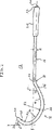
本発明の実施形態による外科用器具は図1〜20に示される。この器具10は、例えば、膣内スリング形成術手順において、身体中に所定長さの材料の挿入を容易にする。器具10は、一般に、細長い中空の管状外側部材12、および外側部材12内を少なくとも部分的に通過するような形状の一般に可撓性であるスタイレット14を含む。外側部材12は、長軸セクション16、および長軸セクション16から遠位方向に延びる弧状セクション18を含む。外側部材12は、好ましくは、ステンレス鋼のような生体適合性材料から形成される。外側部材は、組織への外傷を防ぐために鈍い非外傷性表面を有するべきである。ハンドル20は、その近位端22に隣接する外側部材13に固定されている。
【0018】
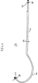
ここで図2を参照して、外側部材12は、外側部材12の近位端22から遠位端32まで延びる貫通ボア30を有する。好ましくは、貫通ボア30は、均一直径d1を有して均一直径である。長軸方向セクション16は、長軸Xを規定する。外側部材12は、疑問符にほぼ似ている形状を有している。弧状セクション18は、近位部分36、中央部分38、および遠位部分40を含む。近位部分36は、長軸方向セクション16から離れて、そして長軸Xから離れて第1の方向Y1に延びる。近位部分36は、この長軸セクション16から離れて湾曲し、そして曲率半径R1を有する。中央部分は、近位部分36から延び、そして第1の方向とは反対の長軸Xに向かって第2の方向Y2に延びる。この中央部分は、長軸Xに向かって湾曲し、そして曲率半径R2を有している。遠位部分40は、中央部分38から延び、そして長軸Xに向かって第2の方向Y2に延びる。この遠位部分40は、長軸に向かって湾曲し、そして曲率半径R3を有する。
【0019】
本発明の特定の好ましい実施形態では、この外側部材12は、少なくとも2つの異なる曲率半径を有する。示される実施形態では、中央部分38は、近位部分の曲率半径R1とは異なる曲率半径R2を有している。この外側部材は、さらなる曲率半径を有し得る。例えば、特定の好ましい実施形態は、中央部分38の曲率半径R2とは異なる曲率半径R3をもつ遠位部分40を有する。好ましくは、示される実施形態では、R3はR2より小さい。これは、遠位部分40を、長軸Xに対する垂直軸Yから離れて湾曲するかまたは再湾曲して戻る。好ましくは、遠位部分40は、垂直軸Yに対して所定の角度を形成する。これは、図2で最もよく観察される。さらに、この遠位部分40は、R3がR2より小さいとき、外側部材12の弧状セクション18を閉鎖する傾向にある。
【0020】
弧状セクション18は、一般に、2つの異なる曲率半径を含むが、弧状セクション18には、例えば、R4、R5などの1つ以上の異なる曲率半径、または連続的に変化する曲率半径が提供され得る。この外側部材12の形状は、以下に論議されるように、器具が身体中に意図された様式で配置されることを可能にする。
【0021】
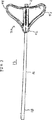
図3を参照して、ハンドル20は、望ましくは、「デルタ」ウイング形状、または側方に延びる部分をもつ形状を有する。このハンドル20は、テーパー状の前端部42およびウイング様の側方突出部44を有する。これは、人間工学的形状を提供し、外側部材12の心地良くかつ正確な操作を容易にする。好ましくは、ハンドル20は、プラスチック材料から形成され、そして外側部材12の近位端22に隣接して固定される。このハンドル20は、好ましくは、外側部材12上で、弧状セクション18が配置される平面にほぼス垂直な平面内に配置されるように配向される。このハンドルの配向は、手順において意図された様式で器具の操作を容易にする。
【0022】
外側部材12は、スタイレット14を受容する。スタイレット14は、円錐形チップ24、およびそれを通って所定長さの材料の受容のための穴またはスロット28を有する近位端26を含む。上記に注記されたように、スタイレット14は、身体内を通る所定長さの材料を引っ張るために提供される。これは、直接、または上記外側部材12の貫通ボア30を通ってなされ得る。ここで、図4を参照して、スタイレット14は可撓性材料から形成され、そしてほぼ外側部材12の形状を有し、長いセクション46およびこの長いセクション46から遠位方向に延びる湾曲したセクション48を含む。スタイレット14は、外側部材12を通過するように十分可撓性であり、そして貫通ボア30の直径より小さい外径d2を有する。外側部材12からのスタイレット14の分離を避けながら、器具10の挿入を可能にするために、円錐形先端24は、貫通ボア30の直径より大きい外径d3を有する。
【0023】
好ましくは、スタイレット14は、例えば、青のような、外科的手順の間に組織に対して容易に目に見える色で形成される。このような外科的手順の間、身体の内部を見るための器具、例えば、膀胱鏡検査を実施するための用具が用いられ得る。好ましくは、スタイレット14は、膀胱鏡検査またはその他の技法もしくは用具を用いる間に、スタイレット14の可視化を容易にする色を有している。
【0024】
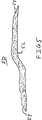
上記に注記されたように、器具10は、例えば、膣内スリング形成技術手順におけるような、身体中に、かつ身体を通って所定長さの材料の挿入を容易にするように設計されている。図5を簡単に参照して、テープ50のような材料が尿道を支持するために用いられ得る。テープ50は、尿道を支持するためのほぼ均一な中央部分52、およびスタイレット14の近位端26中のスロット28を通るテープ50の挿入を容易にするためのテーパー状端部54を有する。テーパー状の端部54は、好ましくは、中央部分に対する角度(゜)がゼロであり、スタイレット14のスロット28中への挿入を容易にする。このテープは、マルチフィラメントまたはモノフィラメントのメッシュ材料を含む任意のメッシュから作製され得る。好ましくは、このテープは、米国特許第5,292,328号の特定の実施形態中に開示される材料から形成され、その開示は、本明細書中に参考として本明細書によって援用される。好ましくは、テープ50は、Tyco Healthcare Inc.の部門である、United States Surgicalから入手可能な、ポリプロピレンで編まれたテープSurgiPro(登録商標)から形成される。この材料は、尿道を支持するために十分な強度を提供し、そして本明細書で以下により詳細に説明されるように、皮下にこのテープの端部の係留を可能にする。あるいは、異なるタイプの編まれたまたは織られた構造、被覆または半吸収性材料を有するその他の材料を用いてもよい。好ましくは、このテープは、相対的に成形しやすいマルチフィラメントのメッシュを含む。このような材料は、より成形しにくいメッシュまたはモノフィラメントのストランドを含むメッシュより、組織に対して磨耗性がより少ない。
【0025】
尿道を支持するための所定長さのテープを挿入するための器具の使用をここで説明する。この手順は、一般に、器具を、骨盤の閉鎖孔を通り、正中線膣切開まで挿入することを含む。次いで、テープを組織を通って通過するためにスタイレットが用いられ得る。これは、1つの側面上で行われ、そして次に反対側の側面上で繰り返される。テープは、中央尿道の下に位置決めされ、尿道を支持し、抑制を達成する。挿入の間、テープは、閉鎖孔を通り、この閉鎖孔の上の皮膚切開を超える点まで延び、牽引による調節を可能にする。調節の後、テープの両端部は皮下に区分化され、そしてすべての切開は閉鎖される。手術の後、繊維状組織の内生長がテープを通じて生じる。
【0026】
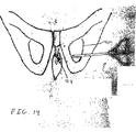
図3を参照して、恥骨に対する膣のスケッチが示されている。示されるように、閉鎖孔(OF)が、膣(VA)および尿道(U)に隣接する骨盤(PB)の両側に存在する。
【0027】
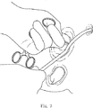
ここで、図7および8を参照して、尿道の中央の直接下の膣壁中に1〜2センチメートルの正中線切開が形成される。解剖はさみを用い、膣組織が両側にある閉鎖孔に向かって側方に約2センチメートルの深さまで解剖される。この閉鎖孔の下方の内部リムは、指の検査により識別される。小さな1センチメートルの皮膚切開が、この閉鎖孔の最下方−中央部分に作製される。作製される切開のサイズは、変化し得、そして外科医に依存する。
【0028】
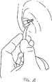
図7〜9を参照して、器具は外側部材12とともに、約45゜の角度で、そして正中線に向かい、斜めに下方に向けて保持され、ハンドル20は、床に向かって斜めに指し示す。円錐形先端24は、閉鎖孔の上の切開中に挿入される。器具の円錐形先端24は、閉鎖膜が貫通されるまで、注意深く内側に押される。この動きの間に、器具の角度は、変化しないままである。
【0029】
図10および11を参照して、一旦、器具の先端が閉鎖膜を貫通すると、器具ハンドルは、身体に対して90゜の角度に向かって回転される。片腕を用い、次いで、ハンドルは、患者から離れかつ正中線に向かって回転され、器具の先端を、閉鎖孔を通り、骨の内面の周りで、そして膣切開に向かって通過させる(図12を参照のこと)。
【0030】
図13および14を参照して、器具の先端の膣切開中への退去は、外科医の自由な手の指により案内されるべきである。この器具の動きは、器具のハンドルが完全に180゜回転され、そして器具の先端が膣切開を出るまで継続される。図13に最もよく観察されるように、この器具は、閉鎖孔の上の切開から膣切開まで延びる。
【0031】
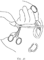
図15を参照して、次に、スタイレット14が外部部材12を通じて引っ張られ、そして外側部材12から除去される。スタイレット14は、逆の位置にある外側部材12の貫通ボア中に、スロット28がこの器具の膣端で剥き出るように再挿入される。次いで、テープ50がスタイレット14中のスロット28中に貫かれ、そして器具を抜き、テープ50の膣と閉鎖孔の上の皮膚切開との間への配置を可能にする(図17)。
【0032】
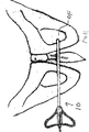
図18および19を参照して、この手順は、次いで、テープ50を、中央尿道の下で、両側にある閉鎖孔に側方に向かって延びて位置決めするために反対側の側面上で繰り返される。
【0033】
本発明のさらなる実施形態では、スタイレットは、外側部材12から除去されず、そしてスタイレット14の位置が逆にならないように再挿入される。器具が第1の側面上の閉鎖孔を通過した後、テープ、外側部材12の近位端を出るスタイレット14中のスロット28中に挿入され得る。スタイレット14は、外側管状部材を通って引かれ、テープ50を膣切開を通って外に引く。その後、器具が取り出され得、テープ50を、閉鎖孔の上の切開から、閉鎖孔を通り、そして膣切開の外に延びて残す。第2の側面上の閉鎖孔に対する手順は、上記で論議されたのと同じである。
【0034】
いずれの手順の間でも、器具の外側管状部材は、周辺の身体組織との係合からテープを遮蔽し、それによって組織への外傷を防ぐことが注記されるべきである。一旦、テープが、各閉鎖孔を通り、そして両切開から出て、尿道の正中線の下に位置決めされると、次いで、テープは、尿道の下で平坦に位置決めされるように、牽引により調節される。外側管状部材は、この調節の間に尿道中に挿入され得、尿道の添え木として作用する。一旦、適正に調節されると、テープの自由端部は、皮下に区分化され、そして膣切開および各閉塞器孔上の切開は閉鎖されて手順が終了する。このアプローチは、骨アンカー、またはさらなる係留構造を必要としない。患者の組織が、テープの両端をその場に保持する。約24時間以内に、テープ中への組織内生長が始まり、これは、テープをさらに固定する。
【0035】
本発明のさらなる実施形態では、上記手順が、図7〜19に関連して上記で論議したように実施されるが、器具が第1の側面上の閉鎖孔を通じて位置決めされた後、外側部材12が取り出され、スタイレット14を患者の身体中の場所に残すことが異なる。スタイレット14およびテープ50は、外側部材12から別個に身体を通って引かれ得る。
【0036】
本発明のさらなる実施形態では、図7〜19に関連して上記で論議されたように実施されるが、器具が第1の側面上の閉鎖孔を通じて位置決めされた後が異なる。スタイレットは外側部材を通って引かれ、テープを、膣切開から閉鎖孔の上の切開まで引く。
【0037】
ここで、図20を参照して、例えば、上記で閉鎖筋器具10に関して記載されたスタイレット14のようなスタイレットとともに用いられる外側管状部材の代替の実施形態が示されている。外側管状部材60は、一般に、長軸Xを規定する長軸方向セクション62、および外側管状部材12に関して本明細書で上記に説明されたのと類似の様式で長軸方向セクション62から遠位方向に延びる弧状セクション64を含む。望ましくは、外側管状部材60は、外側管状部材60の近位端68に隣接して形成された凹部66をさらに含み、ハンドル部材の配置を容易にする。
【0038】
外側管状部材60の好ましい実施形態では、R1は17.5ユニット、そしてR2およびR3は、それぞれ、23および25ユニットである。角度Aは約33゜である。
【0039】
図1〜5と組合せて上記で論議された実施形態では、内側スタイレットは、望ましくは、鈍い先端を備える。この鈍い先端は、組織を通る無作法なトンネル通過のため、および閉鎖膜を貫くために十分である。その他の実施形態では、この管状外側部材、内側スタイレット、または両方は、鋭利な先端を有し得る。
【0040】
図1〜5と組合せて上記で論議された実施形態では、スタイレットは、所定長さのテープを受容するためのスロットを備える。その他の実施形態では、この器具は、図1〜5と組合せて上記で論議されるようであるが、スタイレットがテープの対応する部分に係合するスナップ組(snap−together)部分のような、テープをスタイレットに取り付けるための構造を備えることが異なる。その他の実施形態では、この器具は、図1〜5と組合せて上記で論議されるようであるが、外側管状部材が、所定長さのテープを受容するためのスロットを備えることが異なる。さらなる実施形態では、外側管状部材は、テープの対応する部分に係合するスナップ組(snap−together)部分のような、テープをスタイレットに取り付けるための構造を備える。
【0041】
さらなる実施形態では、器具は、図1〜5に関連して上記で論議されたようであるが、テープがテープの端部の間に配置された拡大部分を有することが異なる。さらなる実施形態では、テープは、矩形、円形、楕円形、弧状などのようなその他の形態を有する。
【0042】
器具は、上記で論議されたように、管状外側部材および内側スタイレット、または単一の導入器要素を備え得る。この管状外側部材および内側スタイレットは、スタイレットの位置が管状部材に対して逆転され得るという利点を有している。換言すれば、スロット、またはテープに係合するためのその他の構造が、外側部材の近位端または外側部材の遠位端に位置決めされ得る。さらに、この管状外側部材は、テープが外側部材を通って引かれるとき、身体からテープを遮蔽する。単一の導入器要素を採用する実施形態では、テープから身体を通過するとき、このテープを囲うためのシースが所望され得る。
【0043】
本明細書中の発明は、特定の実施形態を参照して説明してきたが、これらの実施形態は、本発明の原理および適用の単なる例示であることが理解されるべきである。従って、多くの改変が例示の実施形態になされ得ること、およびその他の配列が、添付の特許請求の範囲によって規定されるような本発明の思想および範囲を逸脱することなく考案され得ることを理解すべきである。例えば、本発明の実施形態は、上記で論議された外側管状部材および内側スタイレットに対して、単一の導入器要素を包含する。特定の実施形態では、最小侵襲性手順で身体中に材料を通過するための外科用器具は、長軸を規定する長軸方向セクション、およびこの長軸方向セクションから遠位方向に延びる弧状セクションを備え、この弧状セクションは、少なくとも2つの異なる曲率半径を有している。望ましくは、この材料は、メッシュ材料のテープを含む。この導入器要素の近位端は、望ましくは、テープの端部を受容するように適合されている。その他の実施形態では、この導入器要素の遠位端は、望ましくは、テープの端部を受容するために適合されている。
【0044】
特定の実施形態では、最小侵襲性手順で身体中に材料を通過するための外科用器具は、長軸を規定する長軸方向セクション、およびこの長軸方向セクションから遠位方向に延びる弧状セクションを備え、この弧状セクションは、使用におけるとき、かつ身体中の位置にあるとき、弧状セクションが閉鎖孔の上の皮膚から、閉鎖孔を通り、膣壁まで延びる寸法であり、かつ湾曲している。上記材料は、望ましくは、メッシュ材料のテープを含む。望ましくは、導入器要素の近位端は、テープの端部を受容するよう適合されている。その他の実施形態では、導入器要素の遠位端は、望ましくは、テープの端部を受容するように適合されている。
【0045】
特定の実施形態では、最小侵襲手順で身体中に材料を通過させるための外科用器具は、長軸を規定する長軸方向セクション、およびこの長軸方向セクションから遠位-方向に延びる弧状セクションを有する導入器要素を備え、この弧状セクションはこの長軸から離れて第1の方向に湾曲する近位部分を有し、この弧状セクションはこの長軸に向かって第2の方向に湾曲する遠位部分を有している。上記材料は、望ましくは、メッシュ材料のテープを含む。この導入器要素の近位端は、望ましくは、テープの端部を受容するよう適合されている。その他の実施形態では、この導入器要素の遠位端は、望ましくは、テープの端部を受容するように適合されている。
【0046】
本発明のさらなる局面では、最小侵襲手順で身体中に材料を通過させるための外科用器具は、長軸を規定する長軸方向セクション、およびこの長軸方向セクションから遠位-方
向に延びる弧状セクションを有する第1の部材を備える。この弧状セクションは、使用におけるとき、かつ身体中の位置にあるとき、弧状セクションが閉鎖孔の上の皮膚から、閉鎖孔を通り、膣壁まで延びる寸法であり、かつ湾曲している。この第1の部材の形状は、最小侵襲性手順において、上記材料の身体中への通過を容易にする。この第1の部材の形状は、材料が最小侵襲手順で身体の内側に配置されることを可能にし、その結果、この材料は閉鎖孔を通って延びる。
【0047】
特定の好ましい実施形態では、この第1の部材は、中空の外側管状部材を備える。スタイレットは、この外側管状部材内で少なくとも部分的に移動可能であり、そして材料と係合可能であり、この材料を身体内に通過させる。この中空の管状部材およびスタイレットは、外科医が、このスタイレットを外側管状部材から取り除き、そしてこの外側管状部材に対して反対の位置に再挿入することを可能にする。この構造はまた、上記材料が、骨盤の第1の側面から骨盤の第2の側面まで延びるように、材料の配置を容易にする。
【0048】
好ましくは、弧状セクションの近位部分は、長軸から第1の方向に離れて湾曲し、そして第1の曲率半径を規定する。弧状セクションの遠位部分は、長軸に向かって第2の方向に湾曲し、そして第2の曲率半径を規定する。望ましくは、遠位セクションの部分は、長軸を横切って、第2の方向に延びる。
【0049】
特定の実施形態において、弧状セクションの遠位部分は、第2の曲率半径とは異なる、第3の曲率半径を有する。遠位部分は、中央セクションおよび最遠位セクションを有し得る。中央セクションは、第2の曲率半径を有し、そして最遠位セクションは、第3の曲率半径を有する。特定の実施形態では、この第2の曲率半径は、第3の曲率半径より大きい。その他の実施形態では、この第2の曲率半径は、第3の曲率半径より小さい。
【0050】
上記スタイレットは、望ましくは、可撓性である。特定の好ましい実施形態では、このスタイレットは、材料の端部の受容のために第1の端部にスロットを含む。望ましくは、このスタイレットは、第2の端部で円錐形先端を含む。この円錐形先端の直径は、外側管状部材の内径より大きくてもよい。
【0051】
望ましくは、外側管状部材は、その近位端にハンドルを有する。特定の好ましい実施形態では、このハンドルは、側方に延びる部分を有する。弧状セクションは、第1の平面を規定し、そしてウイングは、第1の平面と実質的に垂直である第2の平面を規定する。
【0052】
好ましくは、上記外科用器具は材料を含み、そして、特定の好ましい実施形態では、ここで、この材料は、ほぼ平坦なテープを含む。このテープの少なくとも1つの端部は、スタイレットがこの少なくとも1つの端部の受容のためのスロットを備える実施形態では、スタイレット中にテープを貫くことの容易さのために所定角度で切断され得る。望ましくは、このテープは、ポリプロピレンストランドを含み得る、マルチフィラメントのストランドを含む材料を含む。この材料は、ほぼ平坦なテープを含み得、そしてスタイレットは、このテープの端部を受容するように適合された近位端を有し得る。この材料は、吸収性材料を含み得る。
【0053】
上記スタイレットは、望ましくは、スタイレットの近位端が管状部材の近位端に隣接して位置決めされるように、管状部材中に位置決めされる。特定の好ましい実施形態では、このスタイレットは、鈍い遠位端を有している。この遠位端は、鈍い円錐形先端を備え得る。その他の実施形態では、このスタイレットは、鋭い遠位端を有する。
【0054】
この弧状部分は、上記長軸から離れて第1の方向に湾曲する近位部分、および上記長軸に向かって第2の方向に湾曲する遠位部分を有する。第1の部材の形状は、最小侵襲手順で身体中に材料の通過を容易にする。第1の部材の形状は、材料が閉鎖孔を通って延びるように、最小侵襲手順で身体の内側にこの材料が配置されることを可能にする。
【0055】
スタイレットは、この外側管状部材内で少なくとも部分的に移動可能であり、そして材料と係合可能であり、身体内にこの材料を通過させる。この中空の外側管状およびスタイレットは、外科医が、この外側管状部材からスタイレットを取り除き、そしてこのスタイレットを外側管状部材に対して反対の位置に再挿入することを可能にする。この構造はまた、上記材料が骨盤の第1の側面から骨盤の第2の側面まで延びるように、この材料の配置を容易にする。
【0056】
好ましくは、上記弧状セクションの近位部分は、長軸から離れて第1の方向に湾曲し、そして第1の曲率半径を規定する。この弧状セクションの遠位部分は、長軸に向かって第2の方向に湾曲し、そして第2の曲率半径を規定する。望ましくは、遠位セクションの部分は、上記長軸を横切って第2の方向に延びる。望ましくは、上記弧状セクションの遠位部分は、少なくとも2つの異なる曲率半径を有する。
【0057】
特定の実施形態では、上記弧状セクションの遠位部分は、上記第2の曲率半径とは異なる第3の曲率半径を有する。この遠位部分は、中央セクションおよび最遠位セクションを有し得る。この中央セクションは、第2の曲率半径を有し、そしてこの最遠位セクションは第3の曲率半径を有する。特定の実施形態では、この第2の曲率半径は、第3の曲率半径より小さい。
【0058】
上記スタイレットは、望ましくは可撓性である。特定の好ましい実施形態では、上記スタイレットは、材料の端部の受容のために、第1の端部にスロットを含む。このスタイレットは、望ましくは、第2の端部に円錐形の先端を含む。この円錐形先端の直径は、上記外側管状部材の内径より大きくてもよい。
【0059】
望ましくは、上記外側管状部材は、その近位端にハンドルを有する。特定の好ましい実施形態では、このハンドルは、側方に延びる部分を有する。上記弧状セクションは、第1の平面を規定し、そしてウイングは、この第1の平面に実質的に垂直である第2の平面を規定する。
【0060】
好ましくは、上記外科用器具は材料を含み、そして特定の好ましい実施形態では、ここで、この材料は、ほぼ平坦なテープを含む。このテープの少なくとも1つの端部は、スタイレットがこの少なくとも1つの端部の受容のためのスロットを備える実施形態では、スタイレット中へのテープの貫通の容易さのために所定の角度で切断され得る。望ましくは、このテープは、ポリプロピレンストランドを含み得る、マルチフィラメントのストランドを含む材料を含み得る。この材料は、ほぼ平坦なテープを含み得、そして上記スタイレットは、このテープの端部を受容するように適合された近位端を有し得る。この材料は、吸収性材料を含み得る。
【0061】
上記スタイレットは、望ましくは、スタイレットの近位端が上記管状部材の近位端に隣接して位置されるように、管状部材内に位置決めされる。特定の好ましい実施形態では、このスタイレットは、鈍い遠位端を有する。この遠位端は、鈍い円錐形先端を備え得る。その他の実施形態では、このスタイレットは鋭い遠位端を有する。
【0062】
尿道の一部分を、所定長さの材料で吊り下げる方法は、長軸方向の近位端および湾曲した遠位端を含む外側管状部材、およびこの管状部材内で移動可能であり、かつ材料の端部を保持するような形状のスタイレットを有する、外科用器具を提供する工程を包含する。この方法は、上記管状部材内にスタイレットを位置決めする工程を含む。膣切開、および閉鎖孔の上に位置される切開が作製される。この外科用器具の湾曲した遠位端は、閉鎖孔の上の切開を通過される。この方法は、この外科用器具を、この湾曲した遠位端が閉鎖孔を通過し、そして膣切開から出るように、操作する工程を含む。スタイレットの近位端は、所定長さの材料の第1の端部と係合し、そしてスタイレットは、管状部材を通って引かれ、所定長さの材料の一部分を、閉鎖孔の上の切開から、そして膣切開を通って引く。
【0063】
上記外側管状部材は、閉鎖孔の上の切開を通じて引かれ得、この閉鎖孔を通り、かつ膣切開から外に延びる所定長さの材料を残す。この外科用器具の湾曲した遠位端を、閉鎖孔の上の切開を通って通過させる工程は、望ましくは、身体に対して上方に約30゜この外科用器具を回転することを含む。この外科用器具は、望ましくは、高められて、上記湾曲した遠位端を、閉鎖孔を通って位置決めする。この外科用器具は、回転されて、湾曲した遠位端を、閉鎖孔を通り、そして膣切開から外に通過させる。
【0064】
尿道の一部分吊り下げる別の方法は、外科用器具の湾曲した遠位端を、この器具が膣切開と、閉鎖孔の上に位置する皮膚切開との間に延びるように通過させる工程を包含する。この外科用器具は、長軸方向の近位端、および湾曲した遠位端を含む外側管状部材、およびこの外側管状部材内で移動可能なスタイレットを有する。このスタイレットは、身体を通って引かれ、身体を通って、膣切開と、閉鎖孔の上の切開との間を延びる、所定長さの材料を引く。
【0065】
望ましくは、上記器具の湾曲した遠位端を通過させる工程は、上記閉鎖孔の上の切開中にこの器具の湾曲した遠位端を挿入すること、およびこの湾曲した遠位端を閉鎖孔を通り、膣切開から出て移動することを含む。望ましくは、上記器具の湾曲した遠位端を通過させる工程は、上記膣切開中に上記湾曲した遠位端を挿入することを含み、上記スタイレットは、望ましくは、上記外側管状部材内に配置される。
【0066】
この-方法は、上記通過させる工程の後に、外側管状部材からスタイレットを引抜く工
程を含み得る。このスタイレットは、上記材料を受容するように適合されたスタイレットの端部が、膣切開に配置されるように、上記管状部材中に再挿入される。この材料は、望ましくは、この材料がスタイレットの端部によって受容されるように配置される。
【0067】
引き抜く工程は、スタイレットを外側管状部材を通じて引き抜くこと、それによって、この材料を外側管状部材を通じて引くこと、および身体を通って外側管状部材を取り除くことを含み得る。この引き抜く工程は、身体からスタイレットおよび外側管状部材を引抜くこと、それによって身体を通って上記材料を引くことを含み得る。
【0068】
望ましくは、上記通過させる工程は、上記器具を身体を通じて骨盤の第1の側面上に通過することを含み、そしてさらに望ましくは、骨盤の第2の側面上を、身体を通って上記器具を通過させることを包含する。
【0069】
望ましくは、上記材料は、第1の端部および第2の端部を有するテープを含み、そして、望ましくは、上記引抜く工程は、身体を通って上記テープの第1の端部を引くこと、および身体を通って上記テープの第2の端部を引くことを含む。
【図面の簡単な説明】
【0070】
【図1】図1は、本発明の実施形態による外科的手順における使用のための器具の側面図である。
【図2】図2は、図1の実施形態による器具の外側部材の側面図である。
【図3】図3は、図1および図2の実施形態による器具の外側部材の底面図である。
【図4】図4は、図1〜3の実施形態による器具のスタイレットの側面図である。
【図5】図5は、図1〜4の実施形態による器具とともに用いられる所定長さの材料の斜視図である。
【図6】図6は、膣の骨盤に対する関係を示すスケッチである。
【図7】図7は、本発明のさらなる実施形態による外科的手順の初期ステージの間の膣領域の白黒写真である。
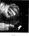
【図8】図8は、図7の実施形態による手順において、骨盤の閉鎖孔の近傍の器具の初期位置決めの間の、図7に類似の白黒写真である。
【図9】図9は、図7および8の実施形態による手順において、図8と同じステージにおける器具を示すスケッチである。
【図10】図10は、図7〜9の実施形態による手順におけるさらなるステージで、身体に対して約45゜に回転した器具を示す白黒写真である。
【図11】図11は、図7〜10の実施形態による手順において、図10と同じステージにおける器具を示すスケッチである。
【図12】図12は、図7〜11の実施形態による手順のさらなるステージにおいて、身体に対して約90゜回転した器具を示す白黒写真である。
【図13】図13は、図7〜12の実施形態による手順のさらなるステージで、閉鎖孔を通過するために180゜回転した器具を示す白黒写真であり、器具の先端が膣切開を出ている。
【図14】図14は、図7〜13の実施形態による手順において、図13と同じステージにある器具を示すスケッチである。
【図15】図15は、図7〜14の実施形態による手順のさらなるステージで、スタイレット中を貫くテープを示すスケッチである。
【図16】図16は、図7〜15の実施形態による手順のさらなるステージで、膣を通って引っ張られるテープを示す白黒写真である。
【図17】図17は、図7〜16の実施形態による手順において、図16と同じステージで、閉鎖孔を通る切開および膣切開から膣の外に延びるテープを示すテープを示すスケッチである。
【図18】図18は、図7〜17の実施形態による手順のさらなるステージにおいて、テープの第2の端部を受けるための位置にある器具を示す白黒写真である。
【図19】図19は、図7〜18の実施形態による手順のさらなるステージにおいて、骨盤の両側面上の各閉鎖孔を通過し、そして尿道を支持するテープを示すスケッチである。
【図20】図20は、本発明のさらなる実施形態による器具の外側管状部材の側面図である。【Technical field】
[0002]
(background)
(1. Technical field)
The technical field relates to insertion instruments for inserting material into the body, and more particularly to insertion tools and methods for inserting support structures or materials into the body to provide support to the urethra.
[Background]
[0003]
(2. Background of related technology)
One problem that occurs in women due to advanced age or onset of trauma is urinary stress incontinence. Several treatments have been developed to correct or alleviate this condition, such as drug treatment and surgical procedures. In some cases, it is necessary to implant a temporary or permanent structure to support the midline of the urethra to control drainage.
[0004]
Several surgical procedures have been developed to place support against the urethra. Many of these procedures require the use and installation of bone anchors to secure the end of this support to the pubic bone. These procedures are fairly invasive and require complex instruments to install the bone anchor in the pubic bone.
[0005]
One exemplary device and method for inserting a sling support into the body to support the urethra in a minimally invasive manner, in certain embodiments, is disclosed in US Pat. No. 5,112,344 by Petros. Has been. The Petros reference discloses the use of an instrument to insert a length of tape through an incision in the abdomen and vagina so that the tape supports the urethra. Bone anchors or other auxiliary structures are not used to anchor the tape. During insertion of the tape into the body using the instrument, the instrument passes through the patient's body on either side of the bladder. Although this instrument is designed to pass safely from an incision in the vagina to an incision in the abdomen, the surgeon typically performs a cystoscopy to check the integrity of the bladder.
DISCLOSURE OF THE INVENTION
[Problems to be solved by the invention]
[0006]
It would be desirable to have other methods for inserting support structures or materials into the body in a minimally invasive manner without having to pass instruments through the body on either side of the bladder.
[Means for Solving the Problems]
[0007]
(wrap up)
In accordance with the present invention, there is provided a surgical instrument for passing material through the body in a minimally invasive procedure, comprising a longitudinal section defining a major axis and an arcuate section extending distally from the major axis section. A proximal portion of the arcuate section that curves away from the major axis in a first direction and defines a first radius of curvature; and the proximal portion The portion of the arcuate section in the distal direction is curved in a second direction toward the major axis and defines a second radius of curvature (R2, R3). The shape of this first member facilitates the passage of the material into the body with a minimally invasive procedure. The shape of the first member is that the material is Closure It can be placed inside the body with minimal invasive procedures to extend through the hole.
[0008]
In certain preferred embodiments, the first member comprises a hollow outer tubular member. A stylet is at least partially movable within the outer tubular member and is engageable with the material for passing the material through the body. The hollow outer tubular member and stylet allow the surgeon to remove the stylet from the outer tubular member and reinsert the stylet in an opposite position relative to the outer tubular member. This structure also facilitates placement of the material such that the material extends from the first side of the pelvis to the second side of the pelvis.
[0009]
A proximal portion of the arcuate section curves away from the major axis in a first direction and defines a first radius of curvature. The distal portion of the arcuate section is curved in a second direction toward the major axis and defines a second radius of curvature. The portion of the distal section desirably extends across the major axis in the second direction.
[0010]
In certain embodiments, the distal portion of the arcuate section has a third radius of curvature that is different from the second radius of curvature. The distal portion may have a central section and a most distal section. The central section has the second radius of curvature and the distal most section has the third radius of curvature. In a particular embodiment, the second radius of curvature is greater than the third radius of curvature. In another embodiment, the second radius of curvature is smaller than the third radius of curvature.
[0011]
Desirably, the stylet is flexible. Desirably, the stylet includes a slot at the first end for receipt of the end of the material. Desirably, the stylet includes a conical tip at the second end. The diameter of the conical tip may be larger than the inner diameter of the outer tubular member.
[0012]
The outer tubular member has a handle at its proximal end. In certain preferred embodiments, the handle has a laterally extending portion. The arcuate section defines a first plane and a second plane in which the wings are substantially perpendicular to the first plane.
[0013]
The surgical instrument preferably further comprises a material, and in certain preferred embodiments, the material now comprises a substantially flat tape. In embodiments where at least one end of the tape comprises a slot for at least one end of the stylet, cut at a predetermined angle for ease of penetrating the tape into the stylet. May be. Desirably, the tape comprises a material comprising multifilament strands, which comprises polypropylene strands. The material can include a substantially flat tape, and the stylet can have a proximal end adapted to receive an end of the tape. This material may comprise an absorbent material.
[0014]
Desirably, the stylet is positioned in the tubular member such that the proximal end of the stylet is positioned adjacent to the proximal end of the tubular member. In certain preferred embodiments, the stylet is Dull (not sharp) Having a distal end. This distal end is dull A conical tip may be provided. In other embodiments, the stylet has a sharp distal end.
[0015]
In the present invention, a surgical instrument for passing material through the body in a minimally invasive procedure is sized and curved, thereby being in use and in position in the body when Closure From the skin above the hole, Closure It may have an arcuate section that extends through the hole to the vaginal wall. The shape of the first member facilitates the passage of the material through the body with a minimally invasive procedure. The shape of the first member is a material, which is the material Closure Allowing it to be placed inside the body with minimally invasive procedures such as extending through a hole.
BEST MODE FOR CARRYING OUT THE INVENTION
[0016]
Various embodiments are described herein with reference to the drawings.
[0017]
Detailed Description of Preferred Embodiments
A surgical instrument according to an embodiment of the present invention is shown in FIGS. 2 It is shown as 0. The
[0018]
Referring now to FIG. 2, the
[0019]
In certain preferred embodiments of the invention, the
[0020]
The
[0021]
Referring to FIG. 3, the
[0022]
[0023]
Preferably, the
[0024]
As noted above, the
[0025]
The use of a device for inserting a length of tape to support the urethra will now be described. This procedure generally involves instrumentation of the pelvis Closure Including insertion through the hole to the midline vaginal incision. A stylet can then be used to pass the tape through the tissue. This is done on one side and then repeated on the opposite side. The tape is positioned below the central urethra to support the urethra and achieve inhibition. During insertion, the tape Closure This through the hole Closure It extends to a point beyond the skin incision above the hole, allowing adjustment by traction. After adjustment, both ends of the tape are sectioned subcutaneously and all incisions are closed. After surgery, ingrowth of fibrous tissue occurs through the tape.
[0026]
Referring to FIG. 3, a sketch of the vagina for the pubic bone is shown. As shown, Closure A hole (OF) exists on both sides of the pelvis (PB) adjacent to the vagina (VA) and urethra (U).
[0027]
Now referring to FIGS. 7 and 8, a 1-2 cm midline incision is made in the vaginal wall directly below the center of the urethra. Using dissection scissors, the vaginal tissue is on both sides Closure It is dissected to a depth of about 2 centimeters laterally towards the hole. this Closure The internal rim below the hole is identified by finger inspection. A small centimeter skin incision Closure Made in the lowermost-central part of the hole. The size of the incision made can vary and depends on the surgeon.
[0028]
Referring to FIGS. 7-9, the instrument is held with the
[0029]
10 and 11, once the tip of the instrument is Closure Upon penetrating the membrane, the instrument handle is rotated toward a 90 ° angle with respect to the body. With one arm, the handle is then rotated away from the patient and toward the midline, Closure Pass through the hole, around the inner surface of the bone, and towards the vaginal incision (see FIG. 12).
[0030]
Referring to FIGS. 13 and 14, removal of the instrument tip into the vaginal incision should be guided by the surgeon's free hand fingers. This instrument movement is continued until the instrument handle has been completely rotated 180 ° and the instrument tip has exited the vaginal incision. As best seen in FIG. 13, the instrument is Closure It extends from the incision above the hole to the vaginal incision.
[0031]
With reference to FIG. 15, the
[0032]
With reference to FIGS. 18 and 19, this procedure then involves
[0033]
In a further embodiment of the invention, the stylet is not removed from the
[0034]
It should be noted that during either procedure, the outer tubular member of the instrument shields the tape from engagement with surrounding body tissue, thereby preventing trauma to the tissue. Once the tape is Closure Once through the hole and out of both incisions and positioned under the midline of the urethra, the tape is then adjusted by traction so that it is positioned flat under the urethra. The outer tubular member can be inserted into the urethra during this adjustment and acts as a splint for the urethra. Once properly adjusted, the free end of the tape is sectioned subcutaneously and the vaginal incision and the incision on each obturator hole are closed to complete the procedure. This approach does not require bone anchors or additional anchoring structures. The patient's tissue holds both ends of the tape in place. Within about 24 hours, tissue growth into the tape begins, which further secures the tape.
[0035]
In a further embodiment of the invention, the procedure is performed as discussed above in connection with FIGS. 7-19, but the instrument is on the first side. Closure After being positioned through the hole, the
[0036]
In a further embodiment of the present invention, implemented as discussed above in connection with FIGS. 7-19, the instrument is on the first side. Closure Different after being positioned through the hole. The stylet is pulled through the outer member and the tape is removed from the vaginal incision. Closure Pull to the incision above the hole.
[0037]
Here, referring to FIG. 20, for example, in the above Obturator An alternative embodiment of an outer tubular member for use with a stylet such as the
[0038]
In a preferred embodiment of the outer
[0039]
In the embodiment discussed above in combination with FIGS. 1-5, the inner stylet is desirably dull Provide tip. this dull The tip is for a rude tunnel through the tissue, and Closure Enough to penetrate the membrane. In other embodiments, the tubular outer member, the inner stylet, or both can have a sharp tip.
[0040]
In the embodiment discussed above in combination with FIGS. 1-5, the stylet comprises a slot for receiving a length of tape. In other embodiments, the device is as discussed above in combination with FIGS. 1-5, but such as a snap-together portion where the stylet engages a corresponding portion of the tape. Differing in that it comprises a structure for attaching the tape to the stylet. In other embodiments, the instrument is as discussed above in combination with FIGS. 1-5, except that the outer tubular member comprises a slot for receiving a length of tape. In a further embodiment, the outer tubular member comprises a structure for attaching the tape to the stylet, such as a snap-together portion that engages a corresponding portion of the tape.
[0041]
In a further embodiment, the instrument is as discussed above in connection with FIGS. 1-5, except that the tape has an enlarged portion disposed between the ends of the tape. In further embodiments, the tape has other forms such as rectangular, circular, elliptical, arcuate and the like.
[0042]
The instrument may comprise a tubular outer member and an inner stylet, or a single introducer element, as discussed above. The tubular outer member and inner stylet have the advantage that the position of the stylet can be reversed with respect to the tubular member. In other words, a slot or other structure for engaging the tape can be positioned at the proximal end of the outer member or the distal end of the outer member. In addition, the tubular outer member shields the tape from the body as the tape is pulled through the outer member. In embodiments employing a single introducer element, a sheath may be desired to enclose the tape as it passes through the body from the tape.
[0043]
Although the invention herein has been described with reference to particular embodiments, it is to be understood that these embodiments are merely illustrative of the principles and applications of the present invention. Accordingly, it will be appreciated that many modifications may be made to the illustrated embodiments and that other arrangements may be devised without departing from the spirit and scope of the invention as defined by the appended claims. Should. For example, embodiments of the present invention include a single introducer element for the outer tubular member and inner stylet discussed above. In certain embodiments, a surgical instrument for passing material through the body in a minimally invasive procedure includes a longitudinal section defining a major axis and an arcuate section extending distally from the longitudinal section. And the arcuate section has at least two different radii of curvature. Desirably, the material comprises a tape of mesh material. The proximal end of the introducer element is desirably adapted to receive the end of the tape. In other embodiments, the distal end of the introducer element is desirably adapted to receive the end of the tape.
[0044]
In certain embodiments, a surgical instrument for passing material through the body in a minimally invasive procedure includes a longitudinal section defining a major axis and an arcuate section extending distally from the longitudinal section. This arcuate section, when in use and when in position in the body, Closure From the skin above the hole, Closure It is dimensioned to extend through the hole to the vaginal wall and is curved. The material desirably includes a tape of mesh material. Desirably, the proximal end of the introducer element is adapted to receive the end of the tape. In other embodiments, the distal end of the introducer element is desirably adapted to receive the end of the tape.
[0045]
In certain embodiments, a surgical instrument for passing material through the body in a minimally invasive procedure includes a longitudinal section defining a major axis, and an arcuate section extending distally from the longitudinal section. An arcuate section having a proximal portion curved in a first direction away from the major axis, the arcuate section being distally curved in a second direction toward the major axis Has a part. The material desirably includes a tape of mesh material. The proximal end of the introducer element is desirably adapted to receive the end of the tape. In other embodiments, the distal end of the introducer element is desirably adapted to receive the end of the tape.
[0046]
In a further aspect of the invention, a surgical instrument for passing material through the body in a minimally invasive procedure includes a longitudinal section defining a major axis, and a distal-toward direction from the longitudinal section.
A first member having an arcuate section extending in the direction is provided. This arcuate section, when in use and when in position in the body, Closure From the skin above the hole, Closure It is dimensioned to extend through the hole to the vaginal wall and is curved. The shape of this first member facilitates the passage of the material into the body in a minimally invasive procedure. The shape of this first member allows the material to be placed inside the body in a minimally invasive procedure so that the material is Closure Extends through the hole.
[0047]
In certain preferred embodiments, the first member comprises a hollow outer tubular member. The stylet is at least partially movable within the outer tubular member and is engageable with the material to pass the material through the body. The hollow tubular member and stylet allow the surgeon to remove the stylet from the outer tubular member and reinsert it in the opposite position relative to the outer tubular member. This structure also facilitates material placement such that the material extends from the first side of the pelvis to the second side of the pelvis.
[0048]
Preferably, the proximal portion of the arcuate section curves away from the major axis in a first direction and defines a first radius of curvature. The distal portion of the arcuate section is curved in a second direction toward the major axis and defines a second radius of curvature. Desirably, the portion of the distal section extends in a second direction across the major axis.
[0049]
In certain embodiments, the distal portion of the arcuate section has a third radius of curvature that is different from the second radius of curvature. The distal portion can have a central section and a most distal section. The central section has a second radius of curvature and the distal most section has a third radius of curvature. In certain embodiments, the second radius of curvature is greater than the third radius of curvature. In other embodiments, the second radius of curvature is less than the third radius of curvature.
[0050]
The stylet is desirably flexible. In certain preferred embodiments, the stylet includes a slot at the first end for receipt of the end of the material. Desirably, the stylet includes a conical tip at the second end. The diameter of the conical tip may be larger than the inner diameter of the outer tubular member.
[0051]
Desirably, the outer tubular member has a handle at its proximal end. In certain preferred embodiments, the handle has a side extending portion. The arcuate section defines a first plane and the wing defines a second plane that is substantially perpendicular to the first plane.
[0052]
Preferably, the surgical instrument comprises a material, and in certain preferred embodiments, the material now comprises a substantially flat tape. At least one end of the tape is cut at an angle for ease of penetrating the tape into the stylet in embodiments where the stylet includes a slot for receipt of the at least one end. obtain. Desirably, the tape comprises a material comprising multifilament strands, which may comprise polypropylene strands. The material can include a substantially flat tape and the stylet can have a proximal end adapted to receive the end of the tape. This material may comprise an absorbent material.
[0053]
The stylet is desirably positioned in the tubular member such that the proximal end of the stylet is positioned adjacent to the proximal end of the tubular member. In certain preferred embodiments, the stylet is dull It has a distal end. This distal end is dull A conical tip may be provided. In other embodiments, the stylet has a sharp distal end.
[0054]
The arcuate portion has a proximal portion that curves away from the major axis in a first direction and a distal portion that curves in a second direction toward the major axis. The shape of the first member facilitates the passage of material through the body with minimally invasive procedures. The shape of the first member is the material Closure This material can be placed inside the body in a minimally invasive procedure to extend through the hole.
[0055]
The stylet is at least partially movable within the outer tubular member and is engageable with the material to pass the material through the body. The hollow outer tubular and stylet allow the surgeon to remove the stylet from the outer tubular member and reinsert the stylet in the opposite position relative to the outer tubular member. This structure also facilitates placement of the material such that the material extends from the first side of the pelvis to the second side of the pelvis.
[0056]
Preferably, the proximal portion of the arcuate section is curved in a first direction away from the major axis and defines a first radius of curvature. The distal portion of the arcuate section curves in a second direction toward the major axis and defines a second radius of curvature. Desirably, the portion of the distal section extends in a second direction across the major axis. Desirably, the distal portion of the arcuate section has at least two different radii of curvature.
[0057]
In certain embodiments, the distal portion of the arcuate section has a third radius of curvature that is different from the second radius of curvature. The distal portion may have a central section and a most distal section. The central section has a second radius of curvature and the distal most section has a third radius of curvature. In certain embodiments, this second radius of curvature is less than the third radius of curvature.
[0058]
The stylet is desirably flexible. In certain preferred embodiments, the stylet includes a slot at the first end for receipt of the end of the material. The stylet desirably includes a conical tip at the second end. The diameter of the conical tip may be larger than the inner diameter of the outer tubular member.
[0059]
Desirably, the outer tubular member has a handle at its proximal end. In certain preferred embodiments, the handle has a side extending portion. The arcuate section defines a first plane and the wing defines a second plane that is substantially perpendicular to the first plane.
[0060]
Preferably, the surgical instrument comprises a material, and in certain preferred embodiments, the material now comprises a substantially flat tape. At least one end of the tape is cut at a predetermined angle for ease of penetration of the tape into the stylet in embodiments where the stylet includes a slot for receipt of the at least one end. Can be done. Desirably, the tape may comprise a material comprising multifilament strands, which may comprise polypropylene strands. The material can include a substantially flat tape and the stylet can have a proximal end adapted to receive an end of the tape. This material may comprise an absorbent material.
[0061]
The stylet is desirably positioned within the tubular member such that the proximal end of the stylet is positioned adjacent to the proximal end of the tubular member. In certain preferred embodiments, the stylet is dull Having a distal end. This distal end is dull A conical tip may be provided. In other embodiments, the stylet has a sharp distal end.
[0062]
A method of suspending a portion of a urethra with a length of material includes an outer tubular member that includes a longitudinal proximal end and a curved distal end, and is movable within the tubular member and an end of the material. Providing a surgical instrument having a stylet shaped to hold the part. The method includes positioning a stylet within the tubular member. Vaginal incision, and Closure An incision is made that is positioned over the hole. The curved distal end of this surgical instrument is Closure Passed through the incision over the hole. This method allows the surgical instrument to be Closure Maneuvering to pass through the hole and exit the vaginal incision. The proximal end of the stylet engages the first end of the length of material, and the stylet is pulled through the tubular member to draw a portion of the length of material, Closure Pull from the incision over the hole and through the vaginal incision.
[0063]
The outer tubular member is Closure This can be pulled through an incision over the hole Closure Leave a length of material that extends through the hole and out of the vaginal incision. The curved distal end of the surgical instrument, Closure The step of passing through the incision over the hole desirably includes rotating the surgical instrument about 30 degrees upward relative to the body. The surgical instrument is desirably raised to secure the curved distal end, Closure Position through the hole. The surgical instrument is rotated to move the curved distal end Closure Pass through the hole and out through the vaginal incision.
[0064]
Another way to suspend a portion of the urethra is to use the curved distal end of the surgical instrument as a vaginal incision, Closure Passing through a skin incision located above the hole. The surgical instrument has an outer tubular member including a longitudinally proximal end and a curved distal end, and a stylet movable within the outer tubular member. This stylet is pulled through the body, through the body, with a vaginal incision, Closure Pull a length of material that extends between the incision above the hole.
[0065]
Desirably, passing the curved distal end of the instrument comprises the step of Closure Inserting the curved distal end of the instrument during an incision over the hole, and Closure Including moving through the hole and out of the vaginal incision. Desirably, passing the curved distal end of the instrument includes inserting the curved distal end during the vaginal incision, and the stylet is desirably disposed within the outer tubular member. Is done.
[0066]
In this method, after the passing step, the stylet is pulled out from the outer tubular member.
Can include The stylet is reinserted into the tubular member such that the end of the stylet adapted to receive the material is placed in the vaginal incision. This material is desirably arranged so that it is received by the end of the stylet.
[0067]
The drawing step may include withdrawing the stylet through the outer tubular member, thereby pulling the material through the outer tubular member, and removing the outer tubular member through the body. This drawing step may include drawing the stylet and outer tubular member from the body, thereby pulling the material through the body.
[0068]
Desirably, the passing step includes passing the instrument through the body and onto the first side of the pelvis, and more desirably, passing the instrument through the body and over the second side of the pelvis. Including.
[0069]
Desirably, the material includes a tape having a first end and a second end, and desirably, the drawing step pulls the first end of the tape through the body. And pulling the second end of the tape through the body.
[Brief description of the drawings]
[0070]
FIG. 1 is a side view of an instrument for use in a surgical procedure according to an embodiment of the present invention.
FIG. 2 is a side view of the outer member of the instrument according to the embodiment of FIG.
FIG. 3 is a bottom view of the outer member of the instrument according to the embodiment of FIGS. 1 and 2. FIG.
FIG. 4 is a side view of a stylet of an instrument according to the embodiment of FIGS. 1-3.
FIG. 5 is a perspective view of a length of material used with the instrument according to the embodiment of FIGS.
FIG. 6 is a sketch showing the relationship of the vagina to the pelvis.
FIG. 7 is a black and white photo of the vaginal area during the initial stage of a surgical procedure according to a further embodiment of the invention.
FIG. 8 is a diagram of the pelvis in the procedure according to the embodiment of FIG. Closure FIG. 8 is a black and white photograph similar to FIG. 7 during initial positioning of the instrument in the vicinity of the hole.
9 is a sketch showing the instrument at the same stage as FIG. 8 in the procedure according to the embodiment of FIGS. 7 and 8. FIG.
FIG. 10 is a black and white photograph showing the instrument rotated about 45 ° relative to the body at an additional stage in the procedure according to the embodiment of FIGS.
FIG. 11 is a sketch showing the instrument at the same stage as FIG. 10 in the procedure according to the embodiment of FIGS.
FIG. 12 is a black and white photo showing the instrument rotated about 90 ° relative to the body in a further stage of the procedure according to the embodiment of FIGS.
FIG. 13 is a further stage of the procedure according to the embodiment of FIGS. Closure A black and white photo showing the instrument rotated 180 ° to pass through the hole, with the tip of the instrument exiting the vaginal incision.
FIG. 14 is a sketch showing an instrument on the same stage as FIG. 13 in the procedure according to the embodiment of FIGS.
FIG. 15 is a sketch showing the tape penetrating through the stylet at a further stage of the procedure according to the embodiment of FIGS.
FIG. 16 is a black and white photo showing the tape being pulled through the vagina in a further stage of the procedure according to the embodiment of FIGS.
FIG. 17 is the same stage as FIG. 16 in the procedure according to the embodiment of FIGS. Closure FIG. 6 is a sketch showing a tape showing an incision through a hole and a tape extending out of the vagina from a vaginal incision.
FIG. 18 is a black and white photograph showing the instrument in a position to receive the second end of the tape in a further stage of the procedure according to the embodiment of FIGS.
FIG. 19 shows each of the pelvis on each side in a further stage of the procedure according to the embodiment of FIGS. Closure Figure 2 is a sketch showing a tape passing through a hole and supporting the urethra.
FIG. 20 is a side view of an outer tubular member of a device according to a further embodiment of the present invention.
Claims (20)
長軸を規定する長軸方向セクション(16)、および該長軸セクションから遠位方向に延びる弧状セクション(18)を有する第1の部材(12)を備え、該弧状セクションが少なくとも2つの異なる曲率半径を有し、ここで:
該弧状セクションの近位部分(36)が、該長軸から第1の方向に離れて湾曲し、そして第1の曲率半径(R1)を規定し;
該近位部分(36)の遠位方向にある弧状セクションの部分(38、40)が、該長軸に向かって第2の方向に湾曲し、そして第2の曲率半径(R2、R3)を規定し、ここで、該第1の部材が、中空の外側管状部材を備え、該外科用器具が、該外側管状部材内で少なくとも部分的に移動可能であって、かつ身体内で該材料を通過させるために該材料と係合可能であるスタイレット(14)をさらに備え、ここで、該スタイレットが、可撓性であり、ここで、該弧状セクションの遠位部分(40)が、該第2の曲率半径(R2)とは異なる第3の曲率半径(R3)を有する、外科用器具。A surgical instrument (10) for passing material through the body in a minimally invasive procedure:
A first member (12) having a longitudinal section (16) defining a major axis and an arcuate section (18) extending distally from the major section, the arcuate section comprising at least two different curvatures With a radius, where:
A proximal portion (36) of the arcuate section curves away from the major axis in a first direction and defines a first radius of curvature (R1);
A portion of the arcuate section (38, 40) distal to the proximal portion (36) is curved in a second direction toward the major axis and has a second radius of curvature (R2, R3). Wherein the first member comprises a hollow outer tubular member, the surgical instrument is at least partially movable within the outer tubular member, and the material is within the body. further comprising a to pass a possible material engageable stylet (14), wherein the stylet is flexible der is, where the distal portion of the arc-shaped section (40) A surgical instrument having a third radius of curvature (R3) different from the second radius of curvature (R2) .
Applications Claiming Priority (2)
| Application Number | Priority Date | Filing Date | Title |
|---|---|---|---|
| US39790502P | 2002-07-23 | 2002-07-23 | |
| PCT/EP2003/008067 WO2004008977A1 (en) | 2002-07-23 | 2003-07-23 | Ivs obturator instrument and procedure |
Related Child Applications (1)
| Application Number | Title | Priority Date | Filing Date |
|---|---|---|---|
| JP2009178772A Division JP2010000366A (en) | 2002-07-23 | 2009-07-31 | Ivs obturator instrument and procedure |
Publications (3)
| Publication Number | Publication Date |
|---|---|
| JP2006502754A JP2006502754A (en) | 2006-01-26 |
| JP2006502754A5 JP2006502754A5 (en) | 2009-09-24 |
| JP4580756B2 true JP4580756B2 (en) | 2010-11-17 |
Family
ID=30771141
Family Applications (2)
| Application Number | Title | Priority Date | Filing Date |
|---|---|---|---|
| JP2004522567A Expired - Fee Related JP4580756B2 (en) | 2002-07-23 | 2003-07-23 | IVS obturator instrument and procedure |
| JP2009178772A Pending JP2010000366A (en) | 2002-07-23 | 2009-07-31 | Ivs obturator instrument and procedure |
Family Applications After (1)
| Application Number | Title | Priority Date | Filing Date |
|---|---|---|---|
| JP2009178772A Pending JP2010000366A (en) | 2002-07-23 | 2009-07-31 | Ivs obturator instrument and procedure |
Country Status (7)
| Country | Link |
|---|---|
| US (2) | US7094199B2 (en) |
| EP (1) | EP1534154B1 (en) |
| JP (2) | JP4580756B2 (en) |
| AU (1) | AU2003250147B2 (en) |
| CA (1) | CA2493327A1 (en) |
| ES (1) | ES2397221T3 (en) |
| WO (1) | WO2004008977A1 (en) |
Families Citing this family (73)
| Publication number | Priority date | Publication date | Assignee | Title |
|---|---|---|---|---|
| FR2811218B1 (en) | 2000-07-05 | 2003-02-28 | Patrice Suslian | IMPLANTABLE DEVICE FOR CORRECTING URINARY INCONTINENCE |
| US8167785B2 (en) | 2000-10-12 | 2012-05-01 | Coloplast A/S | Urethral support system |
| GB0025068D0 (en) | 2000-10-12 | 2000-11-29 | Browning Healthcare Ltd | Apparatus and method for treating female urinary incontinence |
| US20060205995A1 (en) | 2000-10-12 | 2006-09-14 | Gyne Ideas Limited | Apparatus and method for treating female urinary incontinence |
| GB0108088D0 (en) | 2001-03-30 | 2001-05-23 | Browning Healthcare Ltd | Surgical implant |
| US6911003B2 (en) | 2002-03-07 | 2005-06-28 | Ams Research Corporation | Transobturator surgical articles and methods |
| CA2478448C (en) * | 2002-03-07 | 2011-06-21 | Ams Research Corporation | Transobturator surgical articles and methods |
| ES2254792T3 (en) | 2002-03-14 | 2006-06-16 | Jeffrey E. Yeung | SUTURE ANCHORAGE AND APPROXIMATION DEVICE. |
| ATE487427T1 (en) | 2002-08-02 | 2010-11-15 | Bard Inc C R | SELF-ANCHORING LOOSE AND INTRODUCTION SYSTEM |
| GB0307082D0 (en) | 2003-03-27 | 2003-04-30 | Gyne Ideas Ltd | Drug delivery device and method |
| US7811222B2 (en) * | 2004-04-30 | 2010-10-12 | Ams Research Corporation | Method and apparatus for treating pelvic organ prolapse |
| US8439820B2 (en) * | 2004-05-06 | 2013-05-14 | Boston Scientific Scimed, Inc. | Systems and methods for sling delivery and placement |
| GB0411360D0 (en) | 2004-05-21 | 2004-06-23 | Mpathy Medical Devices Ltd | Implant |
| US7527588B2 (en) * | 2004-09-15 | 2009-05-05 | Ethicon, Inc. | System and method for surgical implant placement |
| EP1865873A4 (en) * | 2005-03-22 | 2013-01-09 | Covidien Ag | Mesh implant |
| US8216254B2 (en) | 2005-05-20 | 2012-07-10 | Neotract, Inc. | Anchor delivery system with replaceable cartridge |
| US7896891B2 (en) | 2005-05-20 | 2011-03-01 | Neotract, Inc. | Apparatus and method for manipulating or retracting tissue and anatomical structure |
| US8394113B2 (en) | 2005-05-20 | 2013-03-12 | Neotract, Inc. | Coiled anchor device |
| US8425535B2 (en) | 2005-05-20 | 2013-04-23 | Neotract, Inc. | Multi-actuating trigger anchor delivery system |
| US9149266B2 (en) | 2005-05-20 | 2015-10-06 | Neotract, Inc. | Deforming anchor device |
| US8945152B2 (en) | 2005-05-20 | 2015-02-03 | Neotract, Inc. | Multi-actuating trigger anchor delivery system |
| US7758594B2 (en) | 2005-05-20 | 2010-07-20 | Neotract, Inc. | Devices, systems and methods for treating benign prostatic hyperplasia and other conditions |
| US9034001B2 (en) | 2005-05-20 | 2015-05-19 | Neotract, Inc. | Slotted anchor device |
| US9549739B2 (en) | 2005-05-20 | 2017-01-24 | Neotract, Inc. | Devices, systems and methods for treating benign prostatic hyperplasia and other conditions |
| US7909836B2 (en) | 2005-05-20 | 2011-03-22 | Neotract, Inc. | Multi-actuating trigger anchor delivery system |
| US8157815B2 (en) | 2005-05-20 | 2012-04-17 | Neotract, Inc. | Integrated handle assembly for anchor delivery system |
| US8529584B2 (en) | 2005-05-20 | 2013-09-10 | Neotract, Inc. | Median lobe band implant apparatus and method |
| US10925587B2 (en) | 2005-05-20 | 2021-02-23 | Neotract, Inc. | Anchor delivery system |
| US9504461B2 (en) | 2005-05-20 | 2016-11-29 | Neotract, Inc. | Anchor delivery system |
| US9364212B2 (en) | 2005-05-20 | 2016-06-14 | Neotract, Inc. | Suture anchoring devices and methods for use |
| US8333776B2 (en) | 2005-05-20 | 2012-12-18 | Neotract, Inc. | Anchor delivery system |
| US8628542B2 (en) | 2005-05-20 | 2014-01-14 | Neotract, Inc. | Median lobe destruction apparatus and method |
| US10195014B2 (en) | 2005-05-20 | 2019-02-05 | Neotract, Inc. | Devices, systems and methods for treating benign prostatic hyperplasia and other conditions |
| US8603106B2 (en) | 2005-05-20 | 2013-12-10 | Neotract, Inc. | Integrated handle assembly for anchor delivery system |
| US8834492B2 (en) | 2005-05-20 | 2014-09-16 | Neotract, Inc. | Continuous indentation lateral lobe apparatus and method |
| US8668705B2 (en) | 2005-05-20 | 2014-03-11 | Neotract, Inc. | Latching anchor device |
| US8491606B2 (en) | 2005-05-20 | 2013-07-23 | Neotract, Inc. | Median lobe retraction apparatus and method |
| US7645286B2 (en) | 2005-05-20 | 2010-01-12 | Neotract, Inc. | Devices, systems and methods for retracting, lifting, compressing, supporting or repositioning tissues or anatomical structures |
| CA2617437A1 (en) | 2005-08-04 | 2007-02-08 | C.R. Bard, Inc. | Pelvic implant systems and methods |
| US7878970B2 (en) | 2005-09-28 | 2011-02-01 | Boston Scientific Scimed, Inc. | Apparatus and method for suspending a uterus |
| WO2007059199A2 (en) | 2005-11-14 | 2007-05-24 | C.R. Bard, Inc. | Sling anchor system |
| US9144483B2 (en) | 2006-01-13 | 2015-09-29 | Boston Scientific Scimed, Inc. | Placing fixation devices |
| CA2644983C (en) | 2006-03-16 | 2015-09-29 | Boston Scientific Limited | System and method for treating tissue wall prolapse |
| AU2007248452B2 (en) * | 2006-05-05 | 2012-09-27 | Avent, Inc. | Soft tissue tunneling device |
| US8480559B2 (en) | 2006-09-13 | 2013-07-09 | C. R. Bard, Inc. | Urethral support system |
| US20080208223A1 (en) * | 2007-02-26 | 2008-08-28 | Paul Edward Kraemer | Cable clamping device and method of its use |
| CA2677386C (en) * | 2007-03-02 | 2013-07-09 | Universite De Liege | Surgical technique and tools for use in treatment of male urinary incontinence |
| US8758366B2 (en) | 2007-07-09 | 2014-06-24 | Neotract, Inc. | Multi-actuating trigger anchor delivery system |
| US8206280B2 (en) | 2007-11-13 | 2012-06-26 | C. R. Bard, Inc. | Adjustable tissue support member |
| US9078728B2 (en) | 2007-12-28 | 2015-07-14 | Boston Scientific Scimed, Inc. | Devices and methods for delivering female pelvic floor implants |
| US9282958B2 (en) | 2007-12-28 | 2016-03-15 | Boston Scientific Scimed, Inc. | Devices and method for treating pelvic dysfunctions |
| US8430807B2 (en) | 2007-12-28 | 2013-04-30 | Boston Scientific Scimed, Inc. | Devices and methods for treating pelvic floor dysfunctions |
| US8449573B2 (en) | 2008-12-05 | 2013-05-28 | Boston Scientific Scimed, Inc. | Insertion device and method for delivery of a mesh carrier |
| US9028509B2 (en) | 2008-12-05 | 2015-05-12 | Boston Scientific Scimed, Inc. | Insertion device for delivery of a mesh carrier |
| US8585578B2 (en) * | 2009-02-05 | 2013-11-19 | Coloplast A/S | Implantable devices, tools and methods for anatomical support |
| US8720446B2 (en) | 2010-06-04 | 2014-05-13 | Coloplast A/S | Sacrocolpopexy support and method of implantation |
| US8696544B2 (en) | 2009-02-05 | 2014-04-15 | Coloplast A/S | Minimally invasive adjustable support |
| US9125716B2 (en) | 2009-04-17 | 2015-09-08 | Boston Scientific Scimed, Inc. | Delivery sleeve for pelvic floor implants |
| US8622886B2 (en) | 2010-03-16 | 2014-01-07 | Ethicon, Inc. | Surgical instrument and method for the treatment of urinary incontinence |
| US8911348B2 (en) | 2010-09-02 | 2014-12-16 | Boston Scientific Scimed, Inc. | Pelvic implants and methods of implanting the same |
| US9161749B2 (en) | 2011-04-14 | 2015-10-20 | Neotract, Inc. | Method and apparatus for treating sexual dysfunction |
| ITMO20110178A1 (en) * | 2011-07-22 | 2013-01-23 | Ncs Lab S R L | DEVICE FOR THE TRANSOSSEAL INSERTION OF SUTURE WIRES. |
| US9168120B2 (en) | 2011-09-09 | 2015-10-27 | Boston Scientific Scimed, Inc. | Medical device and methods of delivering the medical device |
| US10292801B2 (en) | 2012-03-29 | 2019-05-21 | Neotract, Inc. | System for delivering anchors for treating incontinence |
| US10130353B2 (en) | 2012-06-29 | 2018-11-20 | Neotract, Inc. | Flexible system for delivering an anchor |
| US9814555B2 (en) | 2013-03-12 | 2017-11-14 | Boston Scientific Scimed, Inc. | Medical device for pelvic floor repair and method of delivering the medical device |
| US9216105B2 (en) | 2013-03-14 | 2015-12-22 | Medicele, Llc. | Rectocele and cystocele device |
| US9072582B2 (en) | 2013-03-14 | 2015-07-07 | Ryan Maaskamp | Rectocele device |
| US9962251B2 (en) | 2013-10-17 | 2018-05-08 | Boston Scientific Scimed, Inc. | Devices and methods for delivering implants |
| ES2953556T3 (en) | 2017-12-23 | 2023-11-14 | Teleflex Life Sciences Ltd | Expandable Tissue Docking Apparatus |
| US11259957B2 (en) | 2019-09-25 | 2022-03-01 | Ryan Maaskamp | Rectocele guide |
| US12167842B2 (en) | 2020-08-03 | 2024-12-17 | Teleflex Life Sciences Llc | Handle and cartridge system for medical interventions |
| US12109099B1 (en) | 2020-09-04 | 2024-10-08 | Athena Surgical, LLC | Surgical implant delivery system and related methods |
Family Cites Families (35)
| Publication number | Priority date | Publication date | Assignee | Title |
|---|---|---|---|---|
| US2897820A (en) | 1956-10-23 | 1959-08-04 | Tauber Robert | Surgical needle guiding instrument |
| US3182662A (en) | 1962-07-25 | 1965-05-11 | Vithal N Shirodkar | Plastic prosthesis useful in gynaecological surgery |
| US3372695A (en) | 1965-04-27 | 1968-03-12 | Prosit Service Corp | Method of overcoming incontinence |
| US3763860A (en) | 1971-08-26 | 1973-10-09 | H Clarke | Laparoscopy instruments and method for suturing and ligation |
| US3924633A (en) | 1974-01-31 | 1975-12-09 | Cook Inc | Apparatus and method for suprapubic catheterization |
| US4172458A (en) | 1977-11-07 | 1979-10-30 | Pereyra Armand J | Surgical ligature carrier |
| US4235238A (en) | 1978-05-11 | 1980-11-25 | Olympus Optical Co., Ltd. | Apparatus for suturing coeliac tissues |
| US4392495A (en) | 1981-08-31 | 1983-07-12 | Bayers Jon Herbert | Apparatus for and method of suturing tissue |
| US4493323A (en) | 1982-12-13 | 1985-01-15 | University Of Iowa Research Foundation | Suturing device and method for using same |
| US4509516A (en) | 1983-02-24 | 1985-04-09 | Stryker Corporation | Ligament tunneling instrument |
| GB8611129D0 (en) | 1986-05-07 | 1986-06-11 | Annis D | Prosthetic materials |
| JP2717868B2 (en) * | 1988-10-04 | 1998-02-25 | エマニエル ペトロス、ペーター | Surgical medical instruments |
| WO1990003766A1 (en) * | 1988-10-04 | 1990-04-19 | Peter Emanuel Petros | Surgical instrument prosthesis and method of utilisation of such |
| US5368595A (en) | 1990-09-06 | 1994-11-29 | United States Surgical Corporation | Implant assist apparatus |
| US5439467A (en) | 1991-12-03 | 1995-08-08 | Vesica Medical, Inc. | Suture passer |
| US5403328A (en) | 1992-04-22 | 1995-04-04 | United States Surgical Corporation | Surgical apparatus and method for suturing body tissue |
| US5578044A (en) | 1992-09-04 | 1996-11-26 | Laurus Medical Corporation | Endoscopic suture system |
| US5540704A (en) | 1992-09-04 | 1996-07-30 | Laurus Medical Corporation | Endoscopic suture system |
| US5458609A (en) | 1992-09-04 | 1995-10-17 | Laurus Medical Corporation | Surgical needle and retainer system |
| US5364408A (en) | 1992-09-04 | 1994-11-15 | Laurus Medical Corporation | Endoscopic suture system |
| US5281237A (en) | 1992-09-25 | 1994-01-25 | Gimpelson Richard J | Surgical stitching device and method of use |
| JPH06163090A (en) * | 1992-11-25 | 1994-06-10 | Yazaki Corp | Connector |
| US5474543A (en) | 1993-05-17 | 1995-12-12 | Mckay; Hunter A. | Single needle apparatus and method for performing retropublic urethropexy |
| US5507754A (en) | 1993-08-20 | 1996-04-16 | United States Surgical Corporation | Apparatus and method for applying and adjusting an anchoring device |
| SE506164C2 (en) | 1995-10-09 | 1997-11-17 | Medscand Medical Ab | Instruments for the treatment of urinary incontinence in women |
| US5899909A (en) | 1994-08-30 | 1999-05-04 | Medscand Medical Ab | Surgical instrument for treating female urinary incontinence |
| US5643288A (en) | 1995-06-14 | 1997-07-01 | Incont, Inc. | Apparatus and method for laparoscopic urethropexy |
| US6053935A (en) * | 1996-11-08 | 2000-04-25 | Boston Scientific Corporation | Transvaginal anchor implantation device |
| US5830220A (en) * | 1997-03-13 | 1998-11-03 | Wan; Shaw P. | Suturing instrument |
| US6096041A (en) * | 1998-01-27 | 2000-08-01 | Scimed Life Systems, Inc. | Bone anchors for bone anchor implantation device |
| WO2000074633A2 (en) * | 1999-06-09 | 2000-12-14 | Ethicon, Inc. | Method and apparatus for adjusting flexible areal polymer implants |
| US7121997B2 (en) * | 1999-06-09 | 2006-10-17 | Ethicon, Inc. | Surgical instrument and method for treating female urinary incontinence |
| US6273852B1 (en) | 1999-06-09 | 2001-08-14 | Ethicon, Inc. | Surgical instrument and method for treating female urinary incontinence |
| ATE424769T1 (en) * | 2000-11-20 | 2009-03-15 | Ethicon Inc | SURGICAL INSTRUMENT FOR THE TREATMENT OF FEMALE URINARY INCONTINENCE |
| AUPR969701A0 (en) | 2001-12-20 | 2002-01-24 | Petros, Peter Emmanuel Dr | Surgical instrument |
-
2003
- 2003-07-23 ES ES03765106T patent/ES2397221T3/en not_active Expired - Lifetime
- 2003-07-23 JP JP2004522567A patent/JP4580756B2/en not_active Expired - Fee Related
- 2003-07-23 EP EP03765106A patent/EP1534154B1/en not_active Expired - Lifetime
- 2003-07-23 WO PCT/EP2003/008067 patent/WO2004008977A1/en active Application Filing
- 2003-07-23 US US10/522,450 patent/US7094199B2/en not_active Expired - Lifetime
- 2003-07-23 CA CA002493327A patent/CA2493327A1/en not_active Abandoned
- 2003-07-23 AU AU2003250147A patent/AU2003250147B2/en not_active Ceased
-
2006
- 2006-07-14 US US11/486,776 patent/US7288063B2/en not_active Expired - Fee Related
-
2009
- 2009-07-31 JP JP2009178772A patent/JP2010000366A/en active Pending
Also Published As
| Publication number | Publication date |
|---|---|
| CA2493327A1 (en) | 2004-01-29 |
| AU2003250147B2 (en) | 2008-06-05 |
| WO2004008977A1 (en) | 2004-01-29 |
| EP1534154A1 (en) | 2005-06-01 |
| US7288063B2 (en) | 2007-10-30 |
| EP1534154B1 (en) | 2012-12-19 |
| ES2397221T3 (en) | 2013-03-05 |
| JP2010000366A (en) | 2010-01-07 |
| US7094199B2 (en) | 2006-08-22 |
| US20060258897A1 (en) | 2006-11-16 |
| JP2006502754A (en) | 2006-01-26 |
| US20050261718A1 (en) | 2005-11-24 |
| AU2003250147A1 (en) | 2004-02-09 |
Similar Documents
| Publication | Publication Date | Title |
|---|---|---|
| JP4580756B2 (en) | IVS obturator instrument and procedure | |
| US20240297350A1 (en) | Insertion device and method for delivery of a mesh carrier | |
| US7828715B2 (en) | Method of treating anal incontinence | |
| EP1909672B1 (en) | Implant introducer | |
| US8123671B2 (en) | Pelvic implant systems and methods | |
| JP2004509685A (en) | Medical devices and methods for delivering hanging bandages in the treatment of stress urinary incontinence in women | |
| WO2007109759A2 (en) | Female urinary incontinence treatment device and method | |
| EP2608736B1 (en) | Centering aid for implantable sling | |
| US20160015385A1 (en) | Puncture apparatus | |
| AU2015201961B2 (en) | Method of treating anal incontinence | |
| AU2013201412B2 (en) | Method of treating anal incontinence |
Legal Events
| Date | Code | Title | Description |
|---|---|---|---|
| A621 | Written request for application examination |
Free format text: JAPANESE INTERMEDIATE CODE: A621 Effective date: 20060601 |
|
| A977 | Report on retrieval |
Free format text: JAPANESE INTERMEDIATE CODE: A971007 Effective date: 20090528 |
|
| A131 | Notification of reasons for refusal |
Free format text: JAPANESE INTERMEDIATE CODE: A131 Effective date: 20090608 |
|
| A524 | Written submission of copy of amendment under article 19 pct |
Free format text: JAPANESE INTERMEDIATE CODE: A524 Effective date: 20090731 |
|
| A521 | Request for written amendment filed |
Free format text: JAPANESE INTERMEDIATE CODE: A821 Effective date: 20090731 |
|
| A131 | Notification of reasons for refusal |
Free format text: JAPANESE INTERMEDIATE CODE: A131 Effective date: 20100126 |
|
| A601 | Written request for extension of time |
Free format text: JAPANESE INTERMEDIATE CODE: A601 Effective date: 20100423 |
|
| A602 | Written permission of extension of time |
Free format text: JAPANESE INTERMEDIATE CODE: A602 Effective date: 20100506 |
|
| A601 | Written request for extension of time |
Free format text: JAPANESE INTERMEDIATE CODE: A601 Effective date: 20100525 |
|
| A602 | Written permission of extension of time |
Free format text: JAPANESE INTERMEDIATE CODE: A602 Effective date: 20100614 |
|
| A601 | Written request for extension of time |
Free format text: JAPANESE INTERMEDIATE CODE: A601 Effective date: 20100625 |
|
| A602 | Written permission of extension of time |
Free format text: JAPANESE INTERMEDIATE CODE: A602 Effective date: 20100702 |
|
| A521 | Request for written amendment filed |
Free format text: JAPANESE INTERMEDIATE CODE: A523 Effective date: 20100726 |
|
| TRDD | Decision of grant or rejection written | ||
| A01 | Written decision to grant a patent or to grant a registration (utility model) |
Free format text: JAPANESE INTERMEDIATE CODE: A01 Effective date: 20100823 |
|
| A01 | Written decision to grant a patent or to grant a registration (utility model) |
Free format text: JAPANESE INTERMEDIATE CODE: A01 |
|
| A61 | First payment of annual fees (during grant procedure) |
Free format text: JAPANESE INTERMEDIATE CODE: A61 Effective date: 20100830 |
|
| FPAY | Renewal fee payment (event date is renewal date of database) |
Free format text: PAYMENT UNTIL: 20130903 Year of fee payment: 3 |
|
| R150 | Certificate of patent or registration of utility model |
Free format text: JAPANESE INTERMEDIATE CODE: R150 |
|
| R250 | Receipt of annual fees |
Free format text: JAPANESE INTERMEDIATE CODE: R250 |
|
| R250 | Receipt of annual fees |
Free format text: JAPANESE INTERMEDIATE CODE: R250 |
|
| R250 | Receipt of annual fees |
Free format text: JAPANESE INTERMEDIATE CODE: R250 |
|
| R250 | Receipt of annual fees |
Free format text: JAPANESE INTERMEDIATE CODE: R250 |
|
| LAPS | Cancellation because of no payment of annual fees |