EP2829209B1 - Appareil d'aspiration empilable - Google Patents
Appareil d'aspiration empilable Download PDFInfo
- Publication number
- EP2829209B1 EP2829209B1 EP14002153.6A EP14002153A EP2829209B1 EP 2829209 B1 EP2829209 B1 EP 2829209B1 EP 14002153 A EP14002153 A EP 14002153A EP 2829209 B1 EP2829209 B1 EP 2829209B1
- Authority
- EP
- European Patent Office
- Prior art keywords
- suction
- suction device
- container
- housing
- device housing
- Prior art date
- Legal status (The legal status is an assumption and is not a legal conclusion. Google has not performed a legal analysis and makes no representation as to the accuracy of the status listed.)
- Active
Links
Images


Classifications
-
- A—HUMAN NECESSITIES
- A47—FURNITURE; DOMESTIC ARTICLES OR APPLIANCES; COFFEE MILLS; SPICE MILLS; SUCTION CLEANERS IN GENERAL
- A47L—DOMESTIC WASHING OR CLEANING; SUCTION CLEANERS IN GENERAL
- A47L5/00—Structural features of suction cleaners
- A47L5/12—Structural features of suction cleaners with power-driven air-pumps or air-compressors, e.g. driven by motor vehicle engine vacuum
- A47L5/22—Structural features of suction cleaners with power-driven air-pumps or air-compressors, e.g. driven by motor vehicle engine vacuum with rotary fans
- A47L5/36—Suction cleaners with hose between nozzle and casing; Suction cleaners for fixing on staircases; Suction cleaners for carrying on the back
- A47L5/365—Suction cleaners with hose between nozzle and casing; Suction cleaners for fixing on staircases; Suction cleaners for carrying on the back of the vertical type, e.g. tank or bucket type
-
- A—HUMAN NECESSITIES
- A47—FURNITURE; DOMESTIC ARTICLES OR APPLIANCES; COFFEE MILLS; SPICE MILLS; SUCTION CLEANERS IN GENERAL
- A47L—DOMESTIC WASHING OR CLEANING; SUCTION CLEANERS IN GENERAL
- A47L7/00—Suction cleaners adapted for additional purposes; Tables with suction openings for cleaning purposes; Containers for cleaning articles by suction; Suction cleaners adapted to cleaning of brushes; Suction cleaners adapted to taking-up liquids
- A47L7/0095—Suction cleaners or attachments adapted to collect dust or waste from power tools
-
- A—HUMAN NECESSITIES
- A47—FURNITURE; DOMESTIC ARTICLES OR APPLIANCES; COFFEE MILLS; SPICE MILLS; SUCTION CLEANERS IN GENERAL
- A47L—DOMESTIC WASHING OR CLEANING; SUCTION CLEANERS IN GENERAL
- A47L9/00—Details or accessories of suction cleaners, e.g. mechanical means for controlling the suction or for effecting pulsating action; Storing devices specially adapted to suction cleaners or parts thereof; Carrying-vehicles specially adapted for suction cleaners
- A47L9/0009—Storing devices ; Supports, stands or holders
-
- B—PERFORMING OPERATIONS; TRANSPORTING
- B25—HAND TOOLS; PORTABLE POWER-DRIVEN TOOLS; MANIPULATORS
- B25H—WORKSHOP EQUIPMENT, e.g. FOR MARKING-OUT WORK; STORAGE MEANS FOR WORKSHOPS
- B25H3/00—Storage means or arrangements for workshops facilitating access to, or handling of, work tools or instruments
- B25H3/006—Storage means specially adapted for one specific hand apparatus, e.g. an electric drill
Definitions
- the invention relates to a mobile suction device, in particular a construction site or workshop suction device having a suction cup and a suction unit arranged therein for generating a suction flow, according to the preamble of claim 1.
- Such a suction device starts, for example EP 1 269 903 A2 out.
- suction device is for example in DE 8912526 U1 mentioned.
- the known suction device is arranged for example in a drawer of a transport box.
- further containers for example for tools and the like, can be arranged.
- cylindrical projections are provided, for example, which engage in arranged on the underside of the upper container plug-in receptacles, so that thereby coupling means are formed.
- a suction hose is removable, for example, from a drawer which receives the suction unit or can be inserted into a storage box of a box. In a usually rather bulky suction hose but this is not easy to implement.
- the EP 2 551 210 A1 describes a mobile suction device according to the preamble of independent claim 1.
- the container attachment can fulfill various tasks, for example, provide storage space for a suction hose, serve for the storage of an electrical connection cable or the like. Also, other functions that are not available in the basic suction device, can be outsourced in the container essay, so to speak. For example, the container attachment can provide a further storage volume for dust, dirt or the like or at least one operating element or display element for operating the basic suction device.
- the connecting means may comprise, for example, one or more passage openings for a line which can be connected or connected to the vacuum cleaner connection, or be formed by at least one passage opening.
- the line is the suction line, for example a suction hose, an electrical line or both.
- a combination line is used, that is, for example, that on the suction hose itself also electrical connection means are provided, for example, for operating an arranged at the free end of the suction line electric brush.
- the vacuum cleaner connection is expediently arranged on an upper side of the sucker housing, on which the container attachment can be arranged.
- the vacuum cleaner connection advantageously comprises the suction inlet.
- the passage opening expediently communicates with the suction inlet of the sucker housing, so that the suction line can be connected or connected to the suction inlet through the passage opening.
- the suction line can extend away from the container attachment in the direction of the work site.
- the passage opening allows, for example, a passage through the suction line.
- the advantage here is that, for example, a plug connection is plugged into the suction line directly into the suction inlet of the sucker housing, for example, fits this form-fitting. Additional interfaces are not present, i. a risk of leakage in the suction line is low.
- a connection element for connection to the suction inlet of the sucker housing is provided and the suction line with the connection element for establishing a flow connection to the suction inlet of the sucker housing is connectable, for example by means of a connector.
- the container attachment provides the flow connection to the suction inlet of the suction housing and also a connection to which, in turn, the suction line can be connected.
- the connecting means an electrical contact arrangement for producing an electrical Connection between the container attachment and provided on the nipple housing suction device contact arrangement, and the container attachment a control element and / or display element for operating or displaying at least one function of the suction device, which is electrically connected to the electrical contact arrangement and / or connected to the contact arrangement electrical connection, in particular for an electrical connection cable of a hand-held machine tool having.
- the connecting means expediently comprise at least one plug connection for producing an electrical or pneumatic plug connection with the vacuum cleaner housing. It is thus possible, for example, that electrical contacts on the container top communicate with electrical contacts of the sucker housing, so that an electrical connection between the sucker housing and the container top is present. Thus, for example, messages from output means, e.g. a display and / or a speaker, the container top are issued, for example, warnings when the dirt collecting space is full or the like.
- an operating element or display element on the container top communicates via the electrical connections with the nipple housing, for example a control of the suction device.
- a connection to be made between the container attachment and the suction housing via the pneumatic connector, so that, for example, a pneumatic connection, for example for a compressed air tool, of the container attachment with a pneumatic connection of the cleaner housing, as it were the basic suction device, in flow connection stands.
- the at least one passage opening comprises a passage opening for an electrical or pneumatic junction box provided on the nipple housing, so that a plug connection element, for example an electrical or pneumatic plug connection element, can be connected to the junction box through the passage opening.
- a plug connection element for example an electrical or pneumatic plug connection element
- the passage opening may also include a passage opening for at least one operating element or display element for operating the suction device.
- the control element forms, so to speak, a vacuum cleaner connection in the form of an operating connection.
- the operating element may, for example, include a display for indicating a function of the suction device, for example level, engine power or the like.
- the operating element comprises a switching element for switching on and off the suction device.
- the setting of an operating parameter, such as speed, power or the like, may be possible through the passage opening on the control element.
- the container attachment preferably provides a receiving cavity for a line of the suction device, for example the suction line, an electrical connection line or both.
- a line of the suction device for example the suction line, an electrical connection line or both.
- the container attachment has a peripheral wall on which limits the receiving cavity on the periphery.
- the peripheral wall may or may not be closed. It can also have breakthroughs or interruptions.
- the operator simply removes the container attachment from the nipple housing so that the suction device is smaller and easier to transport.
- the receiving cavity is preferably designed as an upwardly open and accessible from above receptacle.
- a suction hose or an electrical connection line can be inserted from above into the receptacle of the container attachment.
- the container attachment comprises a carrying handle assembly for supporting the stack comprising the container attachment and the nipple housing.
- a carrying handle assembly for supporting the stack comprising the container attachment and the nipple housing.
- arranged on the underside of the sucker housing container of the stack can be easily transported in this way.
- a transport box for a tool can be fastened below the sucker housing.
- the carrying handle assembly may include, for example, laterally arranged on the container top, in particular pivotable carrying handles.
- the carrying handle assembly comprises an upwardly projecting carrying handle, for example a kind of handle, web or the like.
- the carrying handle is located approximately in the center of an upper side of the container attachment.
- the carrying handle is expediently designed such that it does not protrude in front of a provided for stacking an upper container top support surface of the container attachment.
- the support surface is formed by a peripheral wall of the container attachment.
- the carrying handle forms a winding aid for winding a line, for example the suction line, in particular a suction hose, or an electrical connection line.
- the suction line can thus, for example, be wound around the carrying handle which, in particular, projects there in the center of the upper side of the container attachment and projects there, for example, in the manner of a dome.
- the suction line relaxes again, it expediently pushes in the direction of the peripheral wall, which limits the receiving cavity of the container attachment.
- the sucker housing expediently has in the region of the upper side of the sucker housing first coupling means for cooperation with second coupling means of the upper container to a tensile strength in the stacking direction coupling of the sucker housing with the upper container.
- the coupling means may comprise, for example, hooks, pivot bars, tabs or the like.
- the container attachment expediently has second coupling means cooperating with the first coupling means of the nipple housing for coupling with the nipple housing that is tensile in the stacking direction. This is advantageous, for example, in connection with the mentioned carrying handle arrangement of the container attachment.
- An advantageous embodiment of the invention provides that the container attachment on its upper side the second Coupling means of the sucker housing has corresponding and suitable for coupling the attachable to the nipple housing container second coupling means.
- the container attachment and the nipple housing have substantially the same coupling means, so that the container can be arranged tensile strength selectively with respect to the stacking direction at the top of the nipple housing and the container attachment.
- the operator can thus optionally arrange the container or the container top of the sucker housing.
- the system concept goes so far that, for example, a stack consisting of the nipple housing, the container top and the other container can be formed and the associated coupling means are completely compatible with each other.
- An outer peripheral contour of the nipple housing and an outer peripheral contour of the container cap suitably correspond to each other such that the outer peripheral contour of the nipple housing and the container cap are aligned with each other when the container cap is stacked on the nipple housing.
- the container attachment expediently comprises at least one lateral opening, for example a groove or a passage opening, for the suction line.
- the suction hose, an electrical connection line of the suction device or the like can be inserted into the lateral opening from above or from the side and penetrate it.
- the side opening may be open at the top or side, but it does not have to. It may have a closed outer circumference, so for example be designed as a kind of bore.
- the at least one opening to the top of the container attachment is open, so that the suction line or the electrical connection line or both can be inserted from above into the opening.
- the opening is preferably arranged so deep and / or such that the suction line or electrical connection line accommodated in the opening does not project in front of an upper-side support surface of the container attachment provided for stacking an upper container.
- the opening is provided on a peripheral wall, the upper side of which represents the support surface.
- the opening provided there for the suction line or the electrical connection line are expediently so deep that you can insert the suction line or electrical connection line completely into the opening on the peripheral wall.
- the suction line or electrical connection line does not hinder the placement of a further container on the container attachment in the stacking direction.
- the nipple housing has a base housing and a lid with which an interior of the base housing is closable.
- the container attachment can be mounted on the lid. It is envisaged that the lid of the teat housing with the container top stacked on it can be opened. Thus, the interior of the main body is easily accessible even when the container top is mounted on the lid.
- coupling means for example the aforementioned first coupling means, comprise a locking element for locking the container attachment to the suction cup housing.
- the locking element locks in a locking the container attachment
- the locking element thus absorbs the forces that are necessary to hold the container attachment to the base housing.
- the container attachment expediently has an additional volume, which is additional to the dirt collecting space in the nipple housing, for receiving dirt, for example a pre-separator for dirt.
- the dirt collecting space is provided in a dirt collecting container, which is insertable into a container receptacle of the sucker housing and there in a Saug congress ein the dirt collecting a Saugstrom-outlet of the dirt collecting container with a suction unit inlet of the suction unit is in flow communication, said Dirt collecting container for removing dirt collected in the dirt collecting space is removable from the nipple housing, and in that at least one filter holder for holding at least one filter element of the filter assembly is provided in the dirt collecting container.
- the dirt collector has an example cubic or box-like shape. Thus, therefore, preferably a bottom wall and extending upward away extending side walls are provided.
- a preferred embodiment of the invention provides that an outer peripheral contour of the dirt collecting container correlates with an inner peripheral contour of the container receptacle of the teat housing in such a way that the dirt collecting container can be inserted in a form-fitting manner into the container receptacle.
- An inner peripheral contour of the container receptacle is preferably designed for a positive retention of the dirt collecting container.
- An outer peripheral contour of the dirt collecting container preferably fits completely or at least in sections, preferably substantially, in a form-fitting manner with an inner peripheral contour of the container receptacle.
- the container receptacle expediently comprises a plug-in receptacle into which the dirt collecting container can be inserted.
- the container receptacle is preferably open at the top. It is expediently provided that the dirt collecting container also holds in the container receptacle without locking means. But it is also possible that the suction device comprises locking means for locking the dirt collecting container in the container receptacle.
- the locking means include, for example, hooks, bolts, pivot bolt, sliding bolt or the like. It is also possible that the dirt collecting container is held in a clamping seat in the container receptacle.
- a filter bag can be arranged, that is, that the at least one filter holder comprises a filter holder for a filter bag, so to speak a filter bag filter holder.
- the advantage here is that the dirt contained in the filter bag can be disposed of hygienically.
- the dust collecting space is configured for a direct recording of dirt, dust and the like other particles, that is, that the dirt accumulates directly in the dirt collecting space of the dirt collector and disposed of there.
- the filter bag is not necessary.
- the at least one filter holder comprises a filter holder for a main filter.
- the main filter can be, for example, a filter fleece, a pleated filter or the like.
- the main filter keeps the dirt from getting out of the dirt collection room into the suction unit.
- the main filter works in combination with a filter bag and without filter bag.
- the suction device has a cleaning device for cleaning the main filter, for example by means of countercurrent, shaking, etc.
- the filter holder for the main filter is expediently arranged on the suction flow outlet of the dirt collecting container, so that the suction flow outlet can be closed by the main filter.
- the suction flow thus flows through the main filter in the direction of the suction unit.
- the main filter expediently forms essentially a side wall of the dirt collecting container.
- the suction flow outlet is expediently arranged on a side wall of the container insert and is covered by the main filter. It is particularly preferred if the main filter virtually the entire Side wall surface of the dirt collection container covered, which faces the suction unit.
- the nipple housing and / or the dirt collecting container are expediently closed by a lid.
- a preferred concept provides that the dirt collecting container is open at its top and can be closed by a lid.
- the dirt collecting container prefferably be provided with a cover which is separate from the sucker housing, that is, as it were, a dirt collecting container lid.
- a cover which is separate from the sucker housing, that is, as it were, a dirt collecting container lid.
- the dirt collecting container closed by the dirt collecting container lid can be carried to the place of disposal, for example, a dustbin. This is especially hygienic.
- the suction inlet is expediently arranged on the cover.
- the suction inlet is provided, for example, on a side wall of the sucker housing and corresponding thereto on a side wall of the dirt collecting container.
- connection element or pipe element is arranged at the suction inlet, for example a kind of connection piece.
- the pipe element opens into the dirt collecting space.
- the pipe element is provided and configured to occur in a closing of the lid with a filter disposed in the dirt collecting filter bag, ie its inflow, in flow communication. So if the lid is closed, that gets Pipe element and thus the suction inlet in flow communication with an inflow opening of the filter bag.
- the sucker housing has, for example, a base housing which can be closed by a cover, so to speak a sucker housing cover.
- the nipple housing cover expediently also covers the suction unit and / or at least one accumulation receiver for stowing an accessory of the suction device, e.g. a nozzle or the like, from.
- An advantageous embodiment of the invention provides that the lid for closing the dirt collecting container is formed by the Saugergephinuse cover.
- a sealing arrangement for example comprising O-rings and the like.
- the seal assembly is located on the lid.
- the lid When the lid is opened, it releases the interior of the nipple housing, so that the dirt collector can be removed.
- the lid of the sucker housing simultaneously forms the lid for the dirt collecting container, both are opened in a train, namely the sucker housing and the dirt collecting container, so that a filter bag or the like arranged approximately in the interior of the dirt collecting container can easily and immediately access another filter element, the dirt collecting space or the like is.
- the suction inlet is arranged at the provided for stacking the upper container top of the sucker housing. It is It is a basic idea that the nipple housing can form part of a stack and yet in per se the stacking of a further container preventing manner, the suction inlet is arranged on the top of the nipple housing. As a result, the suction inlet is conveniently accessible from above.
- the sucker housing has, for example, a base housing and a cover with which an interior of the base housing can be closed.
- the suction inlet is expediently provided on the lid. But it is also possible that the suction inlet is provided next to the lid or at least on a fixed area of the top of the teat housing. Thus, while the nipple housing may have a lid, it does not have to.
- the dirt collecting container defines the dirt collecting space and has an inflow opening communicating with or forming the suction inlet for flowing in the suction flow, and a suction flow outlet for discharging air to the suction unit.
- the suction flow outlet of the dirt collection chamber and a suction unit suction inlet of the suction unit is in flow connection via a main filter of the filter arrangement for retaining dirt in the dirt collection space. It is advantageously provided that an outer circumference of the main filter is outside the negative pressure region of the dirt collecting space, so that possibly to the suction additional air flowing into the suction unit inlet secondary air flows from outside the dirt collecting space ago.
- the main filter so to speak not arranged in the vacuum chamber or dirt collecting space is, but in principle between the dirt collecting space and the suction unit inlet. If secondary air flows into this space between the dirt collecting space and the suction unit inlet, which can also be referred to as a sealing gap, it is not dirt laden air from the dirt collecting space, but air from the environment of the suction device, which is generally much cleaner, in any case, contains considerably less dust, particles and other dirt than the suction flow. This secondary air can flow into the suction unit inlet on the one hand. If the seal between on the one hand the dirt collector and on the other hand the suction unit inlet is not perfect, also secondary air, so to speak clean air, can flow past the main filter into the dirt collecting space.
- the main filter may be, for example, a pleated filter, a filter fabric or combinations thereof.
- the main filter has a filter surface that retains particles and other debris in the dirt collecting space.
- a seal is suitably arranged on the outer circumference of the main filter.
- the seal is integrally and / or materially connected to the filter surface of the main filter, for example glued, welded, molded or the like.
- the gasket is, for example, a polyurethane foam, a rubber material, an elastic plastic material or combinations thereof.
- the suction device has a tensioning device for clamping the main filter between the suction flow outlet and an inlet housing region of the suction housing on which the suction unit inlet is arranged, wherein the main filter in a clamping position of the tensioning device between the suction flow outlet and the inlet housing portion is braced.
- the tensioning device can have, for example, movable parts mounted on the dirt collecting container, which can engage with abutment contours on the suction cup housing. But it is also possible that moving parts or clamping elements of the clamping device are arranged on the teat housing and can engage with abutment contours or mating contours on the dirt collector.
- the clamping device may comprise, for example, a clamping screw.
- the clamping screw is advantageous with a hand lever, a knob or the like can be handled easily and without tools.
- the tensioning device expediently has a tensioning gear which, for example, comprises a lever gear, and / or a wedge or bevel gear or the like.
- the tensioning device in particular its tensioning gear, is designed for a linear relative adjustment of the components to be clamped together, so that an end face of the main filter seal with the associated sealing seat on the inlet housing portion or the dirt collecting container is loaded evenly over its entire surface area uniformly with clamping force.
- the direction of movement of the linear adjustment thus runs approximately perpendicular to the end face or the sealing seat.
- the clamping device is provided for clamping the main filter with an inlet housing portion of the nipple housing, on which the suction unit inlet is arranged. In the clamping position of the clamping device of the main filter is then clamped to the inlet housing portion.
- the above-mentioned seal is applied to the inlet housing area.
- a seal may be provided on the inlet housing region, which seal cooperates with the main filter, for example, against the filter surface of the main filter.
- the main filter need not have its own seal, but may also cooperate with a seal, which is provided so to speak from the inlet housing portion or from the dirt collecting container or is arranged there.
- the tensioning device comprises, for example, a lever arrangement, for example a toggle lever arrangement, for adjusting the main filter into the tensioning position.
- the clamping device has a roller arrangement or roller arrangement, with which the main filter can be rolled so to speak into the clamping position.
- an inclined surface arrangement with at least one clamping bevel for adjusting the main filter in the clamping position. It is also possible that a lever arrangement is provided, which is suitable for actuating the inclined surface arrangement, for example for adjusting the at least one clamping bevel.
- a latching device for latching the clamping device in the clamping position is present.
- the latching device can act directly on the main filter.
- the latching means an actuating element, with which the clamping device can be actuated, locked in the clamping position.
- a release device for releasing the main filter from the inlet housing portion or the dirt collecting container is provided.
- the aforesaid gasket it is possible for the aforesaid gasket to bond somewhat more tightly to the inlet housing portion or to the dirt collection container than desired, for example, to adhere.
- the release device makes it possible to detach the main filter from the inlet housing portion or the dirt collecting container, for example linearly move away or swing away.
- the release device comprises, for example, a release bevel or a lever arrangement acting in the sense of a release, or both.
- the clamping device comprises the release device integrally, that is, that the clamping device on the one hand for adjusting the main filter in the clamping position is suitable, on the other hand, but also for releasing the main filter from the clamping position into a release position.
- a carrying handle for example in the form of a bracket, handle or the like, is provided, which is suitable for carrying the dirt collecting container.
- the dirt collector can be worn as a whole.
- the carrying handle may for example be L-shaped or U-shaped.
- a bottom of the sucker housing of the suction device integrally includes the dirt collector, it may be carried as a whole on the carrying handle.
- a dirt collector which can be removed from the teat housing, can be taken so convenient.
- the carrying handle preferably forms an actuating member for actuating the clamping device and / or the release device.
- the carrying handle acts as a lever arm or is pivotally mounted on a lever arm.
- the carrying handle comprises at least one inclined surface of an inclined surface arrangement, for example the aforementioned clamping bevel and / or the LETAschräge or with such, e.g. cooperates with container receptacle arranged slope.
- a plurality of bevels may be provided on the carrying handle, for example at least one clamping bevel and / or at least one release bevel.
- a clamping cam is provided for clamping the main filter in the clamping position.
- a roller or roller or the like may be provided on the carrying handle.
- the dirt collector for example, has solid walls that limit the dirt collecting space, ie a cavity.
- the dirt collector itself about cubic.
- the dirt collecting space is conveniently closed during operation of the suction device except for the inflow port forming or communicating with the suction flow inlet and the suction flow outlet fluidly connected to the suction aggregate inlet.
- the dirt collector preferably forms a kind of capsule for the dirt.
- a variant of the invention for example, in a suction device according to EP 2 229 859 A1 can be realized, provides that the dirt collecting container forms an integral part of the sucker housing.
- the main filter extends over the entire top of the dirt collecting space and / or the dirt collecting container, whereupon the lid is then placed with the suction unit. If then laterally air, namely secondary air, at the density level between the main filter and the suction unit having the lid over in the direction of the suction unit inlet flows, this is relatively clean air.
- the filter does not extend all the way to the outer wall of the sucker housing.
- the atmospheric pressure via a corresponding inflow openings, eg channels and / or a slot can get into the interior up to the density plane between the main filter and suction unit inlet.
- the dirt collecting container for removing dirt accumulated in the dirt collecting space from the sucker housing is removable.
- the above explanations regarding the tensioner and the main filter release means also apply to a removable from the dirt collecting dirt collecting container, that is, that the clamping device for clamping the dirt collecting container in the container receptacle and the release device for releasing the dirt collecting container are configured from the container receptacle. This is particularly easy to implement if the main filter forms part of the dirt collection container or is held there on a filter holder.
- the main filter is arranged at the suction unit inlet and the dirt collecting container, when it is inserted into the container receptacle, is clamped by the clamping device there, so that ensures a tight fit of the main filter in the sealing gap between suction unit inlet and dirt collection is.
- the main filter can indeed, but does not have to be arranged on the dirt collector.
- the main filter may also be arranged on a suction unit having the housing portion of the sucker housing, which can be brought into fluid communication with the dirt collecting container.
- the housing section is adjusted, for example, to the dirt collector out or vice versa, the dirt collector to the housing section.
- the housing portion is a lid similar to a base as in FIG EP 2 229 859 A1 described, is brought.
- the outer circumference of the main filter extends in the manner of a frame around the suction flow outlet forming part of the dirt collecting container.
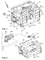
- a mobile suction device 10 comprises a basic device 20 and a container attachment 70 which can be stacked on top of a suction housing 21 of the basic device 20 ( FIGS. 1 and 10 ).
- the suction housing 21 the lower part or base housing 22 as well a cover 23, a suction unit 24 for generating a suction flow, a dirt collecting space 25 and a filter assembly 26 are provided.
- the suction flow flows via a suction inlet 27 into the sucker housing 21 and flows through the dirt collecting space 25, wherein the filter assembly 26 contained in the suction flow dirt, for example dust, sawdust or the like other particles, in the dirt collecting space 25, so that the suction unit 24 in known way soaks filtered air.
- the nipple housing 21 forms a system housing, which with other system components, namely with, for example, the containers 400, 450 in accordance with FIGS. 8 and 9 and with the not according to the invention, on rollers movable on a surface vacuum cleaner 280 according to FIG. 11 can be coupled.
- the base housing 22 has a bottom 28 from which side walls 29, 30, 31, 32 extend upwards. Overall, the base housing 22 has a cubic shape.
- the side wall 29 is a front side wall, the side wall 31 a rear side wall.
- the side walls 30 and 32 are e.g. Transverse side walls, in particular narrow side walls.
- the side walls 29-32 define an interior 33.
- a housing portion 120 is provided, in which the suction unit 24 is arranged protected and encapsulated.
- the housing portion 120 comprises a portion of the bottom 28, the side wall 32 and portions of the side walls 29 and 31.
- the housing portion 120 further comprises a cover 34 which covers the suction unit 24 on the upper side.
- the suction unit 24 is completely housed, except for a arranged on the wall 121 suction unit inlet 61 through which the suction unit 24th sucked in the suction flow, and a not visible in the drawing, for example, arranged on the side wall 31 outflow opening through which the suction unit 24 blows out the suction flow.
- the interior space 33 can be closed by the cover 23.
- the lid 23 has an upper top wall 40 from which side walls 41, 42, 43, 44 extend downwardly.
- the side walls 41-44 are aligned with the side walls 29-32 of the base housing 22 when the lid 23 closes the inner space 33.
- side oblique surfaces 39 are provided, which are overlapped by the side walls 41, 43, 44, when the lid 23 is closed (see FIG. 2 ).
- the lid 23 also closes a container receptacle 45, which is located in the interior 33.
- the container receptacle 45 could serve as a dirt collecting space per se.
- the container receptacle 45 serves to receive a dirt collecting container 46, in which a filter holder 47 and a filter holder 48 are provided.
- the filter holder 47 serves to hold a main filter 49, that is, a filter element.
- a filter bag 50 is fastened ( FIG. 5 ), which is suitable for collecting particles or other dirt and is another filter element.
- the filter bag 50 is disposed in the use state of the suction device 10 in the dirt collecting space 25.
- the filter bag 50 has, for example, a connection plate 51 with an inflow opening 52.
- the connection plate 51 can be hung in a swivel mount 53 of the filter holder 48, so that, for example, the connection plate 51 can be pivoted out of the dirt collecting space 25 (not shown).
- the connection plate 51 could also form part of the filter holder 48.
- the connection plate 51 would be advantageous for example made of plastic, while it is suitably made of cardboard as part of the filter bag 50.
- the dirt collector 46 has a bottom 54 from which side walls 55-58 extend upward. At the top, the dirt collecting container 46 has an access opening 59.
- the dirt collecting space 25 is defined by the side walls 55-58 and the bottom 54. Through the access opening 59 of the dirt collecting space 25 is easily accessible.
- the filter holder 47 for the main filter 49 extends on the side wall 58.
- the filter holder 47 includes, for example, a frame in the interior of the main filter 49 is supported.
- the main filter 49 has a size extent which corresponds approximately to that of the side wall 58, so that virtually the complete side wall 58 is formed by the main filter 49.
- the filter holder 47 extends around a suction flow outlet 60 of the dirt collecting container 46.
- the suction flow outlet 60 is covered by the main filter 49 so to speak, so that only air purified by the main filter 49 flows into the suction unit 24.
- the suction flow outlet 60 of the dirt collector 46 and a suction unit inlet 61 of the suction unit 24 communicate with each other and are in fluid communication with each other.
- connection plate 51 of the filter bag 50 or the filter holder 48 On the side walls 56 and 58 of the dirt collecting container 46 support areas 83 for the connection plate 51 of the filter bag 50 or the filter holder 48 are provided. Thereby, the terminal plate 51 in the in FIG. 5 supported use position supported, so that the inflow opening 52 is ready for flow communication with the suction inlet 27.
- the side walls 55-58 and the bottom 54 define an outer peripheral contour 62 of the dirt collecting container 46, which fits into an inner peripheral contour 63 of the teat housing 21, which fits into the container receptacle 45 in a form-fitting manner.
- the container receptacle 45 and its inner peripheral contour 63 are defined by the side wall 30 and the side walls 29 and 31 and the bottom 28 as well as by the inner wall, not visible in the drawing, containing the suction unit inlet 61.
- the container receptacle 45 is a plug-in receptacle into which the dirt collecting container 46 fits in a form-fitting manner and can be inserted.
- the replacement and replacement of the dirt collector 46 is very simple. It only has to be lifted up out of the container receptacle 45.
- An advantage here is that the operator can easily bring the dirt collecting container 46 to a disposal location and removes there, for example, the filter bag 50 from the dirt collecting container 46.
- the opening and closing of the dirt collecting container 46 is simplified, because in fact no separate lid for the dirt collecting container 46 is necessary, but the lid 23 also fulfills the function of a lid for the dirt collecting container 46.
- a cover section 64 for covering the dirt collecting container 46.
- a seal 65 which, when the lid 23 is closed, lies between the upper end faces of the side walls 41-44 and the lid 23 to come to rest.
- the seal 65 that is a sealing arrangement, serves to close and tightly cover the dirt collecting space 25.
- the dirt collecting space 25 can be closed by the cover 23 except for its suction flow outlet 60 and the suction inlet 27 forming an inflow opening 132.
- the suction flow S which is generated by the suction unit 24, thus flows through the inflow opening 132 into the dirt collecting space 25 and out of the suction flow outlet 60 out of the dirt collecting space 25.
- connection member 86 protruding in front of the underside of the lid 23 or in front of the cover portion 64 comes into fluid communication with the filter bag 50.
- the connector 86 includes, for example, a short protruding tube portion which enters the inlet opening 52 when the lid is closed 23 penetrates.
- the suction device 10 may have one or more operating elements 11, for example a switch 12 for switching on and off the suction device 10 and preferably also for adjusting a power of the suction unit 24.
- the switch 12 is a tap changer and allows e.g. the switching of a first and a second power stage and / or an operating mode of the suction device 10 so that it is switched off or permanently switched on, for example, or automatically switches on and off during operation of the manual power tool 300.
- the operating elements 11 are arranged, for example, on the side wall 32.
- a connection cable such as a hand-held machine tool 300
- the hand machine tool 300 for example, a grinder, a saw, or the like, then turns on and off the suction device 10, for example, by controlling the suction device 10 detects a current flow to the hand machine tool 300.
- the lateral arrangement of the controls 11 on the side wall 32 allows for ergonomic handling of the suction device 10, even if it is in a stack consisting of further, later described components, integrated. That would not be necessary, which will become clear later.
- workpieces for example a workpiece plate 301
- a suction device 10 including a suction line 14, for example a suction hose 18, to the suction inlet 27 can be connected.
- the suction hose 18 has, for example, a connection piece 15, for example a pipe element or the like, which can be inserted into the suction inlet 27 having a plug-in receptacle 68.
- the connecting piece 15 has an angular shape, that is, a plug-in portion 16 provided for insertion into the plug-in receptacle 68 and a connecting portion 17 provided for connecting the suction hose 18 are at right angles to one another at right angles to one another.
- the fitting could also be arcuate.
- the angular or arcuate shape is particularly advantageous in the action described in detail below, ie that the suction hose 18 including its connection piece 15 for a in the in FIG. 2 shown operating mode is conveniently used, in which it is inserted directly into the arranged on the top 69 of the sucker housing 21 suction inlet 27, without being on the top 69 is an object or container or the like, on the other hand, even if a in the FIGS. 6 and 7 shown in detail container top 70 is disposed on the top 69.
- the suction inlet 27 is arranged at the top 69, because one does not readily follow the example in FIG. 8 illustrated container 400 or the in FIG. 9 illustrated container 450 can be arranged on the upper side 69 of the sucker housing 21 when the suction hose 18 to the suction device 10, at least the base unit 20, is arranged.
- the suction device 10 can be used effectively in the form of the basic device 20 ( FIG. 2 ), but also with the extremely convenient and labor-facilitating container attachment 70.
- the container attachment 70 has a bottom wall 71 and thereof upstanding side walls 72, 73, 74, 75 on.
- the container attachment 70 has a cubic shape.
- the carrying handle 77 From the bottom wall 71 is a carrying handle 77 upwards.
- the carrying handle 77 has the shape of a handle, so that the operator can easily grasp the container top 70.
- the carrying handle 77 is expediently located approximately in the center of the bottom wall 71, so that a favorable center of gravity is given.
- the carrying handle 77 is expediently used as a winding aid for in FIG. 6 only partially illustrated suction hose 18.
- This suction hose 18 can thus be wound around the carrying handle 77 around.
- the suction hose 18 has a tendency to relax, that is, he puts, if he experiences no force from the outside, to the inner sides of the side walls 72-75.
- free portions of the side walls 72-75 are expediently inwardly projecting wall portions 78, which further contribute to the fact that the suction hose 18 in the receiving cavity 76, the interior of the container attachment 70, is held.
- the suction hose 18 and the suction line 14 can not only at least partially when not in use of the suction device 10 be arranged in the receiving cavity 76 or the interior of the container attachment 70, but also during operation.
- connection means 80 of the container attachment 70 are seen, which enable a functional coupling of the container attachment 70 with the basic apparatus 20.
- the connecting means 80 comprise, for example, a passage opening 81 on the bottom wall 71.
- the passage opening 81 is aligned with the suction inlet 27 when the container attachment 70 is attached to the suction housing 21.
- the connection piece 15 can pass through the passage opening 81 into the suction inlet 27 be plugged in ( FIG. 1 ). If the suction hose 18 is not needed, it is simply wound up and stowed in the interior of the container attachment 70, that is, the receiving cavity 76. He does not have to be separated from the suction inlet 27.
- the suction hose 18 / the suction line 14 can be guided out of the receiving cavity 76 in an ideal manner.
- On the side wall 75 is a lateral opening 82, whose cross section corresponds to a cross section of the suction line 14 / the suction hose 18, so that the suction line 14 / the suction hose 18, when he / she is received in the opening 82, not in front of the support surfaces 79th protrudes.
- the carrying handle 77 is not in front of the support surfaces 79 upwards.
- an electrical connection line 19 for the electrical power supply of the suction unit 24, for example, a power line, can be conveniently stowed in the container top 70.
- the connection line 19 is arranged on the side wall 32 of the sucker housing 21 and has a plug for plugging into a socket (not shown).
- the connection line 19 can be inserted through a passage opening 84 into the receiving cavity 76, ie the interior of the container attachment 70, and there are stowed there as well as the suction line 14 comfortably.
- connection line 19 together with the suction line 14 through the lateral opening 82 to the outside.
- the passage opening 84 is located in an edge region between the side wall 75 and the bottom wall 71.
- a holding receptacle 85 is provided on the side wall 32 of the sucker housing 21 into which the connection line 19 can be inserted. For this purpose, there is a slot at the front of the holding receptacle 85.
- the base unit 20 further, no longer accessible by a stacking of the container attachment 70 components on its upper side 69, such as a display element and / or control element 87, for switching and adjusting the suction device 10 and / or Display of operating parameters may be suitable, an electrical junction box 88, for example, for plugging in a power cord.
- Passage openings 87a and 88a are expediently provided on the container attachment 70 in this case so that the operating element and / or display element 87 and the connection box 88 remain accessible.
- the passage openings 87a and 88a are expediently arranged on the bottom wall 71.
- the side walls 72-75 protect the in the Passage openings 87a and 88a arranged functional components.
- the connecting line 19, the suction inlet 27 and the junction box 88, the operating element or display element 87 form, just like the contact arrangement 89, in each case a vacuum cleaner connection 100.
- connection means 80 e.g. resilient contact surfaces and / or fixed contact surfaces and / or a plug connection 89b may include or be arranged thereon and when stacking the container attachment 70 on the teat housing 21 into electrical connection with a suction device contact arrangement 89, for example, at the top 69 of the teat housing 21st located.
- an operating element 101 and / or a display element 102 for operating or displaying at least one function of the suction device 10, for example for switching on or off, for displaying a filling level or the like is electrically connected to the actual basic device 20.
- an electrical connection box for example a connection 103 for connecting the hand-held machine tool 300 or another hand-held machine tool, can also be supplied with power via the electrical connection established by the contact arrangements 89, 89a.
- the container top 70 fits ideally into the container and workshop system including the further containers 450 and 400 and the vacuum cleaner 280. This becomes clear below.
- the container attachment 70 and the container 400, 450 and the vacuum cleaner 280 first coupling means 90 are provided which cooperate with second coupling means 110 on the respective lower sides of the aforementioned components, except, of course, the vacuum cleaner 280, the vacuum cleaner housing 281 below by means of rollers 283 on a substrate is movable.
- the first coupling means 90 include, for example, in the case of the vacuum cleaner 280 on its upper side 284 provided holding receptacles 91, in the holding projections 111 of the second coupling means 110 can be inserted.
- the holding receptacles 91 are provided on a receptacle 285 on the upper side 284 of the vacuum cleaner 280 into which, for example, the teat housing 21 can be inserted with its bottom area.
- the receptacle 285 is bounded laterally, for example by side walls 287, 288, wherein on the side wall 288, the retaining seats 91 are arranged.
- On the side walls 287 however, are retaining tabs 92 which are engageable with retaining projections 112 of the second coupling means 110.
- the retaining tabs 92 are for example, slidingly or pivotally mounted on the side walls 287.
- the nipple housing 21 are attached to the top of the vacuum cleaner 280, but also the containers 400, 450, not described in detail, which are suitable for transporting, for example, the hand machine tools 300, tools, accessories and the like.
- the containers 400, 450 and the nipple housing 21 and the container attachment 70 are coupled with each other with somewhat different components of the coupling means 90, 110.
- the coupling means 90 comprise on the upper side 69 of the sucker housing 21, ie on the cover 23, provided Hintergreifabilityn 93 and support receptacles 94, which serve for engagement with Hintergreiff pairingen 113 and for receiving support feet 114 of the other coupling means 110.
- the coupling means 90 comprise on the upper side 69 of the sucker housing 21, ie on the cover 23, provided Schugreifabilityn 93 and support receptacles 94, which serve for engagement with Hintergreiff pairingen 113 and for receiving support feet 114 of the other coupling means 110.
- At the Hintergreifabilityn 93 are Hintergreifkonturen 95, which serve for the positive locking complementary Congressgreifkonturen 115 at the Hintergreiff mergeen 113.
- the Schugreifkonturen 95, 115 are brought into engagement, wherein the respective upper container 400, 450 or the container attachment 70 down, to the top of the respective lower container out, for example, the sucker housing 21 or the sucker housing 21, is pivoted so that with respect Axes transverse to the stacking direction H a positive or shear-resistant hold is given.
- the containers 400, 450 and in any case the nipple housing 21 are constructed on the underside similar to the container attachment 70, i. that there the support feet 114 and the rear grip feet 113 are also provided. On the container 450 also suitable Schugreifkonturen 95 b are provided for engaging the Hintergreifkonturen 115.
- the first coupling means 90 further comprise a locking element 96.
- a respective locking element 96 is rotatably arranged by means of a pivot bearing 98 on the cover 23 and the front side wall 72 of the container attachment 70.
- the latch member 96 has an arcuate receptacle 97 which engages with retaining projections 116 and 117 by rotation.
- the arranged on the lid 23 locking element 96 is in the respective upper container or container attachment 70 coupling locking position or coupling position ( FIG. 1 ) Is rotated so that it is the lid 23 across with the arranged above the lid 23 retaining projection 116 of the upper container or container attachment and the example on the base housing 22 or the container top 70 above, below the locking element 96 frontally arranged retaining projection 117 at the same time engaged.
- the pivot bearing 98 is relieved.
- the locking element 96 couples the respective containers tensile strength with respect to the stacking direction H.
- the coupling between the container attachment 70 and the base unit 20 is made so low that the lid 23 with saddled container attachment 70 can be opened ( FIG. 10 ).
- FIG. 12 is a stack consisting of a container 450, on which the nipple housing 21 of the suction device 10 and in turn the container attachment 70 are arranged, is shown. On the upper side, a further container 450 is stacked on the container attachment 70.
- the coupling means 90 and 110 By the coupling means 90 and 110, the container 450 and the nipple housing 21 of the suction device 10 and the container attachment 70 are firmly connected to each other.
- the locking elements 96 of the lower container 450 and the suction device 10 and the container attachment 70 are adjusted in the respective coupling position.
- a bypass inlet 122 is provided for a bypass valve, not visible in the drawing, through which, if necessary, e.g. when the suction inlet 100 is closed, the suction unit 24 can flow cooling air into the interior of the housing section 120.
- the main filter 49 comprises a seal 123 and a filter surface 124.
- the filter surface 124 which comprises for example a filter fleece or a pleated filter, is accommodated in a frame 125 of the filter holder 47.
- a step 126 which supports the seal 123 at the back.
- the main filter 49 is supported by the filter holder 47 on its opposite side of the wall 121 rear side, so that the dirt collecting container 46 so to speak from behind presses on the seal 123 and this thus against the wall 121, thus against a suction unit inlet 61 having inlet housing portion 127 presses.
- the seal 123 is close to the wall 121, so that the suction flow S from the suction inlet 27 forth first flows through the dirt collecting space 25, where usually a filter bag 50 retains particles, at least the main filter 49, the front of the suction unit inlet 61st is arranged, fulfills this function, so that in principle only clean, at least relatively few particles containing air of the suction flow S flows into the suction unit inlet 61 a.
- the outer periphery 130 is the outer periphery of the main filter 49.
- the secondary air N is not sucked from the negative pressure region 131, that is, the dirt collecting space 25, but from the vicinity of the suction device 10, i. from an area with atmospheric pressure. There, the load with particles is much lower, so that at least not or little contaminated air, namely the secondary air N, flows into the suction unit inlet 61.
- a protective grille 128, which projects in front of the wall 121.
- the grid 128 can protrude into the interior of the seal 123 ( FIG. 15 ).
- the seal 123 is located with its end face close to the wall 121 and surrounds the suction unit inlet 61 annular.
- the bypass inlet 122 is located in the interior and thus in the flow cross section of the seal 123. This need not be.
- the tensioning device 140 comprises as an actuating member a carrying handle 141, which is mounted pivotably on the dirt collecting container 46 by means of pivot bearings 142, for example on its side walls 55, 57 next to the suction flow outlet 60.
- the carrying handle 141 serves to carry the dirt collecting container 46.
- the carrying handle 141 can be arranged between a carrying position T (FIG. FIG. 17 ), in which the carrying handle 141 protrudes upwardly in front of the side walls 55-58 and its base leg 143 can be comfortably grasped by an operator, and a non-use position N (FIG. FIG. 16 ) are pivoted, in which the base leg 143 is not or only slightly protruding upward in front of the upper edges of the side walls 55-58.
- From the base leg 143 side legs 144 are U-shaped, whose free ends are arranged on the pivot bearings 142.
- bearing bolts 145 project in front of the side walls 55, 57 and engage in corresponding bearing receptacles on the side legs 144 of the carrying handle 141.
- the carrying handle 141 is suitably not hinged in a longitudinally central area of the side walls 55, 57, so that the housing of the dirt collecting container 46 when carrying with the carrying handle 141 has a tendency to tilt so that any dirt contained in the dirt collecting container 46 does not affect the main filter 49 presses, so that it is not pressed out of the filter holder 47 out and holds it well.
- This tilting tendency is indicated by an arrow 138 in FIG FIG. 17 indicated.
- the bearing concept of the carrying handle 141 thus provides relief of the main filter 49 advantageous.
- the dirt collecting container 46 can be easily inserted from above by an operator holding the carrying handle 141 into the container receptacle 45. This is indicated by an arrow 146. Then, the carrying handle 141 is pivoted in the direction of an arrow 147, wherein at the same time the clamping device 140 assumes its clamping position P ( FIG. 18 ). In this case, a clamping surface 148 presses against an abutment surface 149 of the sucker housing 21.
- the abutment surface 149 is provided for example by a web 150 in the container receptacle 45.
- a web 150 is provided in each case, namely on the inner sides of the opposite side walls 29 and 31. In this sense, the carrying handle 141 has a respective clamping surface 148 in the side legs 144.
- the clamping surface 148 is located on a clamping cam 151, which projects outwardly in front of the respective side legs 144.
- the two clamping cams 151 and thus also the clamping surfaces 148 are eccentric to the pivot axis 152 of the two pivot bearings 142 about which the carrying handle 141 pivots.
- the webs 150, 158 form side walls of a receiving groove 161 for the clamping cam 151.
- the clamping cam 151 is guided and received in this receiving groove.
- the seal 123 Due to the orientation of the clamping surfaces 148 and the associated abutment surfaces 149 parallel to the end face of the seal 123 and the opposite wall 121, the seal 123 is transverse to the direction indicated by the arrow 146 through axle, along which the dirt collecting container 46 is inserted into the container receptacle 45 evenly pressed against the inlet housing portion 127.
- the corresponding load is indicated by an arrow 139 in FIG FIG. 15 indicated.
- the clamping device 140 is thus configured to a linear relative adjustment of the components to be clamped together and brought into a sealing contact, namely the inlet housing portion 127 and the end face of the seal 123, which is to come to rest thereon. Consequently, the clamping force in the direction of the arrow 139 substantially constant over the entire circumference of the seal 123 end face substantially.
- the tensioning device 140 also tensions the dirt collecting container 46 in the container receptacle 45.
- a catch 153 of a latching device 155 engages in a latching receptacle 154 on the suction housing 21.
- the catch 153 is located approximately transversely on the base leg 143 of the carrying handle 141 and engages in a corresponding mating contour, for example an upper edge of the wall 121, in the sense of latching. This is not only the carrying handle 141, but also the clamping device 140 is locked in its clamping position P.
- the tensioning device 140 at the same time forms or comprises a release device 160 for releasing the tensioning of the dirt collection container 46 in the container receptacle 45 and the tension between the seal 123 and the inlet housing region 127.
- a release bevel 156 on the tensioning cam 151 which pivots during pivoting of the carrying handle 141 against the arrow direction of the arrow 147, ie in the direction of a release position L, is supported on a support surface 157 of the sucker housing 21.
- the support surface 157 is opposite the abutment surface 149.
- the support surface 157 is provided on a further wall projection or web 158.
- the webs 158, 150 are opposite each other and, as already mentioned, in the container receptacle 45 inside the side walls 29, 31 provided opposite each other.
- an insertion bevel 159 is provided on which the clamping cam 151 slides with its release bevel 156 during insertion of the dirt collecting container 46 into the container receptacle 45.
- the insertion 159 forms an assembly aid.
- the insertion bevel 159 is e.g. at the top of the jetty 158.
- FIGS 20-23 are a first to the chuck 140 alternative clamping device 240 with a bevel gear and in the Figures 24-27 a second alternative tensioning device 340 is shown.
- the tensioners 240, 340 are provided to dirt collection tanks 246, 346.
- the provided with the clamping devices 240 and 340 Dirt collecting containers 246 and 346 correspond to the dirt collecting container 46.
- An actuating member of the clamping device 240 forming carrying handle 241 has at its projecting from a base leg 243 side legs 244 each have a groove 251, into which a bearing pin 245 of a sliding bearing 242 engages.
- the bearing pins 245 are laterally from the dirt collector 246 from.
- the carrying handle 241 can be linearly moved up and down between a carrying position T and a non-use position N along a sliding axis 247.
- the carrying handle 241 projects upwards in front of the dirt collecting container 246; in the non-use position N, it is moved closer to the housing of the dirt collecting container 246 so that it does not protrude slightly or slightly upwards in front of the cover 34 when the dirt collecting container 246 is accommodated in the nipple housing 21.
- the grooves 251 extend obliquely with respect to the sliding axis 247 and, in the present case, also with respect to the directions of longitudinal extension of the side limbs 244.
- the inner walls of the grooves 251 provide an inclined surface arrangement 252 due to their oblique course.
- the Carrying handle 241 When the carrying handle 241 is moved from the support position T in the non-use position N, he actuates the clamping device 240 from the release position L in the clamping position P. In this case, the groove 251 slides on the bearing pin 245 along, which represents a backdrop follower or sliding block insofar, said the Carrying handle 241 is adjusted with a clamping surface 248 in the direction of an abutment surface 249. On each side leg 244 each one provided by its longitudinal narrow side clamping surface 248 is present.
- everyone Clamping surface 248 is associated with an abutment surface 249.
- the abutment surfaces 249 are provided, for example, by webs similar to the web 150, which project inwardly into the container receptacle 45.
- a latching recess 254 is provided, into which the bearing pin 245 engages in the clamping position P.
- the bearing pin 245 and the recess 254 form a latch 255.
- the tensioning device 340 comprises a carrying handle 341, which serves as an actuating element for the tensioning device 340.
- a carrying handle 341 which serves as an actuating element for the tensioning device 340.
- rollers 348 of a roller assembly 353 are rotatably mounted, which are supported in a clamping position P on an abutment surface 349.
- the carrying handle 341 is mounted on the dirt collecting container 346 by means of pivoting levers 350.
- the side legs 344 are pivotally mounted, for example by means of a respective pivot bearing 345 on a respective pivot lever 350.
- other joints may be provided.
- the carrying handle 341 could also be mounted on each side leg 344 with, for example, two pivoting levers, pivotably mounted on the dirt collecting container 346.
- the pivot lever 350 in turn are in turn mounted by means of pivot bearings 342 on the dirt collecting 346.
- the carrying handle 341 makes substantially a linear movement between the support position T and the non-use position N by.
- the two rollers 348 move up and down in the receiving groove 161, for example.
- the rollers 348 are based on the in the FIGS. 26 and 27
- the pivot levers 350 pivot about the pivot bearings 342.
- the pivot levers 350 thereby move from the in FIGS. 25 and 26 illustrated upper pivot position in an in FIG. 27 illustrated bottom pivot position across their dead centers, so that over the support by the rollers 348 a clamping force in the direction of arrow 139 is exerted.
- the gasket 123 is thereby tightened against the inlet housing portion 127.
- the pivot lever 350 forms part of a lever arrangement 352.
- the clamping devices 240 and 340 also act as a release device when the respective carrying handles 241 and 341 are adjusted to the carrying position T.
- the substantially linear plug-in clamping movement during insertion of the dirt collecting container 46 in the container receptacle 45 as in the embodiments according to Figures 13-27 the case, to understand by way of example.
- the dirt collecting container 46 for example, by an exemplary in FIG. 14 drawn pivot axis 363 is pivoted into the container receptacle 45, for example, based on a pivot bearing with bearing pin and bearing receptacles on the dirt collector 46 and the container receptacle 45, then in the last movement section, for example, the inclined surfaces 360 and the mating contour 361 in the sense of bracing the main filter 49 with the opposite sealing seat act on the inlet housing portion 127.
- An additional latch, clamping lever or the like can then provide a firm grip of the dirt collecting container 46 in the container receptacle 49 and thus also a tight sealing seat of the main filter 49 on the housing portion 120.
Landscapes
- Engineering & Computer Science (AREA)
- Mechanical Engineering (AREA)
- External Artificial Organs (AREA)
- Filters For Electric Vacuum Cleaners (AREA)
- Cleaning In General (AREA)
Claims (15)
- Appareil d'aspiration (10) mobile, en particulier appareil d'aspiration de chantiers ou d'usine, qui présente un boîtier d'aspirateur (21) et un groupe d'aspiration (24) disposé dans ce dernier pour produire un flux d'aspiration (S), dans lequel le boîtier d'aspirateur (21) présente une admission d'aspiration (27) destinée au raccordement d'un conduit d'aspiration (14) et un ensemble filtrant (26) ainsi qu'un espace de collecte de poussières (25) sont disposés en amont du groupe d'aspiration (24) dans le boîtier d'aspirateur (21), dans lequel le boîtier d'aspirateur (21) est réalisé, au niveau de son côté supérieur (69), afin d'empiler un contenant (400, 450) le long d'une direction d'empilement (H), dans lequel l'appareil d'aspiration (10)
comprend une garniture de contenant (70) pouvant être disposée dans la direction d'empilement (H) sur le côté supérieur (69) du boîtier d'aspirateur (21), dans lequel
le boîtier d'aspirateur (21) présente un boîtier de base (22) et un couvercle (23), avec lequel un espace intérieur du boîtier de base (22) peut être fermé, et en ce que la garniture de contenant (70) peut être montée au niveau du couvercle (23), dans lequel le couvercle (23) du boîtier d'aspirateur (21) peut être ouvert avec la garniture de contenant (70) empilée sur ce dernier, caractérisé en ce que la garniture de contenant (70) présente des moyens de liaison (80) pour établir une liaison avec au moins un raccord d'aspirateur de poussières (100) prévu au niveau du boîtier d'aspirateur (21). - Appareil d'aspiration selon la revendication 1, caractérisé en ce que les moyens de liaison (80) comprennent au moins une ouverture de passage (81, 84, 87a, 88a) pour un conduit, qui peut être raccordé ou est raccordé au raccord d'aspirateur (100).
- Appareil d'aspiration selon la revendication 2, caractérisé en ce que le raccord d'aspirateur de poussières (100) comprend l'admission d'aspiration (27), dans lequel l'admission d'aspiration (27) est disposée au niveau d'un côté supérieur (69) du boîtier d'aspirateur (21), sur lequel la garniture de contenant (70) peut être disposée, et l'ouverture de passage (81, 84, 87a, 88a) communique avec l'admission d'aspiration (27) du boîtier d'aspirateur (21) de sorte que le conduit d'aspiration (14) peut être relié ou est relié à l'admission d'aspiration (27) en passant par l'ouverture de passage (81,84, 87a, 88a), et/ou en ce que l'ouverture de passage (81) permet un emboîtement du conduit d'aspiration (14) ou qu'un élément de raccordement destiné à être relié à l'admission d'aspiration (27) du boîtier d'aspirateur (21) est prévu au niveau de l'ouverture de passage (81), et le conduit d'aspiration (14) peut être relié à l'élément de raccordement afin d'établir une liaison d'écoulement avec l'admission d'aspiration (27) du boîtier d'aspirateur (21), en particulier à l'aide d'un système de liaison par enfichage.
- Appareil d'aspiration selon l'une quelconque des revendications 2 ou 3, caractérisé en ce que l'au moins une ouverture de passage (81, 84, 87a, 88a) comprend une ouverture de passage (88a) pour une prise de raccordement (88) électrique et/ou pneumatique prévue au niveau du boîtier d'aspirateur (21) de sorte qu'un élément de raccordement par enfichage peut être relié à la prise de raccordement (88) au travers de l'ouverture de passage (88a), et/ou une ouverture de passage (87a) pour au moins un élément d'utilisation (87) pour utiliser l'appareil d'aspiration (10), en particulier pour activer et désactiver et/ou pour régler un paramètre de fonctionnement.
- Appareil d'aspiration selon l'une quelconque des revendications précédentes, caractérisé en ce que les moyens de liaison (80) comprennent au moins un raccord par enfichage (89b) pour établir une liaison par enfichage électrique et/ou pneumatique avec le boîtier d'aspirateur (21) et/ou un ensemble de contact (89a) électrique pour établir une liaison électrique entre la garniture de contenant (70) et un ensemble de contact d'appareil d'aspiration (89) prévu au niveau du boîtier d'aspirateur (21), et la garniture de contenant (70) présente un élément d'utilisation (101) et/ou un élément d'affichage (102) pour utiliser ou à afficher au moins une fonction de l'appareil d'aspiration (10), qui est relié de manière électrique à l'ensemble de contact (89a) électrique et/ou qui présente un raccord (103) électrique relié à l'ensemble de contact (89a) électrique, en particulier pour un câble de raccordement électrique d'une machine-outil manuelle (300).
- Appareil d'aspiration selon l'une quelconque des revendications précédentes, caractérisé en ce que la garniture de contenant (70) présente une cavité de logement (76) pour un conduit, en particulier pour le conduit d'aspiration (14) comprenant de manière appropriée un tuyau flexible d'aspiration (18) et/ou pour une ligne de raccordement (19) électrique de l'appareil d'aspiration (10), dans lequel la cavité de logement (76) est configurée de manière avantageuse sous la forme d'un logement ouvert vers le haut et accessible depuis le haut.
- Appareil d'aspiration selon l'une quelconque des revendications précédentes, caractérisé en ce que la garniture de contenant (70) présente un ensemble formant poignée de transport, en particulier une poignée de transport (77) faisant saillie vers le haut, pour porter l'empilement comprenant la garniture de contenant (70) et le boîtier d'aspirateur (21), dans lequel la poignée de transport (77) ou l'ensemble formant poignée de transport ne fait pas saillie de manière avantageuse devant une surface d'appui (79) située côté supérieur, prévue aux fins de l'empilement d'un contenant (400, 450) supérieur, prévue en particulier au niveau d'une paroi périphérique (72 -75), de la garniture de contenant (70) et/ou la poignée de transport (77) forme de manière appropriée une aide à l'enroulement pour enrouler un conduit, en particulier le conduit d'aspiration (14) ou une ligne de raccordement (19) électrique.
- Appareil d'aspiration selon l'une quelconque des revendications précédentes, caractérisé en ce que le boîtier d'aspirateur (21) présente dans la zone du côté supérieur (69) du boîtier d'aspirateur (21), des premiers moyens de couplage (90) pour coopérer avec des deuxièmes moyens de couplage (110) du contenant (400, 450) supérieur afin de coupler de manière résistante à la traction dans la direction d'empilement (H) le boîtier d'aspirateur (21) au contenant (400, 450) supérieur.
- Appareil d'aspiration selon la revendication 8, caractérisé en ce que la garniture de contenant (70) présente des deuxièmes moyens de couplage (110) coopérant avec les premiers moyens de couplage (90) du boîtier d'aspirateur (21), pour le couplage de manière résistante à la traction dans la direction d'empilement (H) avec le boîtier d'aspirateur (21), et/ou en ce que la garniture de contenant (70) présente au niveau de son côté supérieur des deuxièmes moyens de couplage (110) adaptés pour coupler le contenant (400, 450) pouvant être fixé au niveau du boîtier d'aspirateur (21) et correspondant aux deuxièmes moyens de couplage (110) du boîtier d'aspirateur (21) de sorte que le contenant (400, 450) peut être disposé de manière résistante à la traction au choix au niveau du côté supérieur (69) du boîtier d'aspirateur (21) ou de la garniture de contenant (70) par rapport à la direction d'empilement (H).
- Appareil d'aspiration selon l'une quelconque des revendications précédentes, caractérisé en ce qu'un contour périphérique extérieur (62) du boîtier d'aspirateur (21) et un contour périphérique extérieur de la garniture de contenant (70) correspondent entre eux de sortie que les contours périphériques extérieurs du boîtier d'aspirateur (21) et de la garniture de contenant (70) sont au même niveau quand la garniture de contenant (70) est empilée sur le boîtier d'aspirateur (21).
- Appareil d'aspiration selon l'une quelconque des revendications précédentes, caractérisé en ce que la garniture de contenant (70) présente au moins une ouverture (82) latérale, en particulier une rainure, pour le conduit d'aspiration (14), en particulier un tuyau flexible d'aspiration (18), et/ou une ligne de raccordement (19) électrique de l'appareil d'aspiration (10) de sorte que le conduit d'aspiration (14) ou la ligne de raccordement (19) électrique relié/reliée selon la mécanique des fluides au boîtier d'aspirateur (21) peut être guidé/guidée vers l'extérieur en passant par l'ouverture (82) en dehors d'un espace intérieur de la garniture de contenant 70).
- Appareil d'aspiration selon la revendication 11, caractérisé en ce que l'au moins une ouverture (82) est ouverte en direction du côté supérieur de la garniture de contenant (70) de sorte que le conduit d'aspiration (14) ou la ligne de raccordement (19) électrique peuvent être introduits depuis le haut dans l'ouverture (82), et/ou en ce que l'ouverture (82) est profonde et/ou est disposée de telle manière que le conduit d'aspiration (14) ou la ligne de raccordement (19) électrique logé/logée dans l'ouverture (82) ne fait pas saillie devant une surface d'appui (79) située côté supérieur, prévue aux fins de l'empilement d'un contenant (400, 450) supérieur, de la garniture de contenant (70).
- Appareil d'aspiration selon l'une quelconque des revendications précédentes, caractérisé en ce qu'un élément à verrou (96) disposé au niveau du boîtier d'aspirateur (21), formant en particulier un élément constitutif des premiers moyens de couplage (90), pour verrouiller la garniture de contenant (70) au boîtier d'aspirateur (21) dans une position verrouillant la garniture de contenant (70) verrouille la garniture de contenant (70) en recouvrant le couvercle (23) du boîtier de base (22).
- Appareil d'aspiration selon l'une quelconque des revendications précédentes, caractérisé en ce que la garniture de contenant (70) comprend un volume additionnel en supplément de l'espace de collecte de poussières (25), pour loger des saletés, en particulier un séparateur primaire pour les saletés de grande taille, et/ou en ce qu'il présente une poignée de transport (141 - 341) se présentant en particulier sous la forme d'un étrier ou d'une anse, pour porter le contenant de collecte de saletés (46).
- Appareil d'aspiration selon l'une quelconque des revendications précédentes, caractérisé en ce qu'une zone de basse pression (131) se forme dans l'espace de collecte de saletés (25) du contenant de collecte de saletés (46) du fait du fonctionnement du groupe d'aspiration (24), et le contenant de collecte de saletés (46) présente une ouverture de flux entrant (132) communiquant avec l'admission d'aspiration (27) ou formant cette dernière, pour faire affluer le flux d'aspiration (S) et une sortie de flux d'aspiration (60) pour faire sortir le flux d'air en direction du groupe d'aspiration (24), dans lequel la sortie de flux d'aspiration (60) de l'espace de collecte de saletés (25) et une admission de groupe d'aspiration (61) du groupe d'aspiration (24) se trouvent en liaison de communication fluidique par l'intermédiaire d'un filtre principal (49) de l'ensemble de filtre (26) pour retenir les saletés dans l'espace de collecte de saletés (25), et dans lequel une périphérie extérieure (130) du filtre principal (49) se situe à l'extérieur de la zone de basse pression (131) de l'espace de collecte de saletés (25) de sorte que de l'air secondaire supplémentaire affluant dans l'admission de groupe d'aspiration (61) s'écoule en provenant de l'extérieur de l'espace de collecte de saletés (25) éventuellement en plus du flux d'aspiration (S), dans lequel l'appareil d'aspiration présente de manière avantageuse un système de serrage (140 - 340) comprenant en particulier un mécanisme de serrage, pour gauchir le filtre principal (49) entre la sortie de flux d'aspiration (60) et une zone de boîtier d'entrée (127) du boîtier d'aspirateur (21), au niveau de laquelle l'entrée de groupe d'aspiration (61) est disposée et le filtre principal (49) est gauchi dans une position de serrage (P) du système de serrage (140 -340) entre la sortie de flux d'aspiration (60) et la zone de boîtier d'entrée (127).
Priority Applications (1)
| Application Number | Priority Date | Filing Date | Title |
|---|---|---|---|
| EP16188769.0A EP3135168B1 (fr) | 2013-07-23 | 2014-06-24 | Appareil d'aspiration empilable |
Applications Claiming Priority (1)
| Application Number | Priority Date | Filing Date | Title |
|---|---|---|---|
| DE102013012240.6A DE102013012240A1 (de) | 2013-07-23 | 2013-07-23 | Stapelbares Sauggerät |
Related Child Applications (3)
| Application Number | Title | Priority Date | Filing Date |
|---|---|---|---|
| EP16188769.0A Division EP3135168B1 (fr) | 2013-07-23 | 2014-06-24 | Appareil d'aspiration empilable |
| EP16188769.0A Previously-Filed-Application EP3135168B1 (fr) | 2013-07-23 | 2014-06-24 | Appareil d'aspiration empilable |
| EP16188769.0A Division-Into EP3135168B1 (fr) | 2013-07-23 | 2014-06-24 | Appareil d'aspiration empilable |
Publications (3)
| Publication Number | Publication Date |
|---|---|
| EP2829209A2 EP2829209A2 (fr) | 2015-01-28 |
| EP2829209A3 EP2829209A3 (fr) | 2015-04-08 |
| EP2829209B1 true EP2829209B1 (fr) | 2016-11-02 |
Family
ID=51162404
Family Applications (2)
| Application Number | Title | Priority Date | Filing Date |
|---|---|---|---|
| EP14002153.6A Active EP2829209B1 (fr) | 2013-07-23 | 2014-06-24 | Appareil d'aspiration empilable |
| EP16188769.0A Active EP3135168B1 (fr) | 2013-07-23 | 2014-06-24 | Appareil d'aspiration empilable |
Family Applications After (1)
| Application Number | Title | Priority Date | Filing Date |
|---|---|---|---|
| EP16188769.0A Active EP3135168B1 (fr) | 2013-07-23 | 2014-06-24 | Appareil d'aspiration empilable |
Country Status (2)
| Country | Link |
|---|---|
| EP (2) | EP2829209B1 (fr) |
| DE (1) | DE102013012240A1 (fr) |
Families Citing this family (11)
| Publication number | Priority date | Publication date | Assignee | Title |
|---|---|---|---|---|
| WO2018189180A1 (fr) * | 2017-04-11 | 2018-10-18 | Festool Gmbh | Récipient collecteur de particules, pile et procédé |
| WO2018188736A1 (fr) * | 2017-04-11 | 2018-10-18 | Festool Gmbh | Pré-séparateur à cyclone et dispositif |
| DK3582669T3 (da) * | 2017-04-11 | 2023-04-03 | Festool Gmbh | Adapterramme, anordning og sugeindretning |
| EP3692882B1 (fr) * | 2019-02-08 | 2022-10-05 | Luca Valentini | Poste de travail mobile comprenant un dispositif d'aspiration de poussière sous vide mobile et une unité de stockage |
| EP3701849A1 (fr) * | 2019-02-28 | 2020-09-02 | Hilti Aktiengesellschaft | Dispositif aspirateur doté d'une plaque de recouvrement et plaque de recouvrement |
| US12593946B2 (en) | 2019-10-25 | 2026-04-07 | Milwaukee Electric Tool Corporation | Vacuum for use with modular storage system |
| CN114641374B (zh) | 2019-11-15 | 2024-08-27 | 米沃奇电动工具公司 | 用于与模块化储存系统一起使用的真空设备 |
| DE102020209204A1 (de) | 2020-07-22 | 2022-01-27 | Robert Bosch Gesellschaft mit beschränkter Haftung | Modulares Luftreinigungssystem |
| DE102021121707A1 (de) | 2021-08-20 | 2023-02-23 | Festool Gmbh | Sauggerät |
| IT202100030941A1 (it) * | 2021-12-09 | 2023-06-09 | Ivision S R L | Dispositivo di aspirazione |
| TWI867654B (zh) * | 2023-07-31 | 2024-12-21 | 林宥葳 | 手工具工具架 |
Family Cites Families (9)
| Publication number | Priority date | Publication date | Assignee | Title |
|---|---|---|---|---|
| JPS5332625B2 (fr) * | 1972-09-12 | 1978-09-09 | ||
| DE8912526U1 (de) | 1988-10-25 | 1990-02-01 | Messmer, Johannes, 7803 Gundelfingen | Aufbewahrungsvorrichtung |
| DE10130995B4 (de) * | 2001-06-27 | 2009-06-04 | Festool Gmbh | Sauggerät |
| DE102007028086A1 (de) * | 2007-06-11 | 2008-12-18 | Alfred Kärcher Gmbh & Co. Kg | Staubsauger |
| EP2229859B1 (fr) | 2009-03-21 | 2012-04-04 | Festool GmbH | Procédé de fonctionnement pour un appareil d'aspiration doté d'un sac-filtre et appareil d'aspiration correspondant |
| DE102010003756A1 (de) * | 2010-04-08 | 2011-10-13 | Alfred Kärcher Gmbh & Co. Kg | Reinigungsgerät |
| DE102010043577A1 (de) * | 2010-11-08 | 2012-05-10 | Alfred Kärcher Gmbh & Co. Kg | Sauggerät |
| DE202010017035U1 (de) * | 2010-12-29 | 2011-03-24 | Robert Bosch Gmbh | Vorrichtung zur Kopplung mit einem Werkzeugkoffer |
| DE102011108416A1 (de) * | 2011-07-26 | 2013-01-31 | Tts Tooltechnic Systems Ag & Co. Kg | Tragbarer Behälter |
-
2013
- 2013-07-23 DE DE102013012240.6A patent/DE102013012240A1/de active Pending
-
2014
- 2014-06-24 EP EP14002153.6A patent/EP2829209B1/fr active Active
- 2014-06-24 EP EP16188769.0A patent/EP3135168B1/fr active Active
Non-Patent Citations (1)
| Title |
|---|
| None * |
Also Published As
| Publication number | Publication date |
|---|---|
| EP2829209A3 (fr) | 2015-04-08 |
| DE102013012240A1 (de) | 2015-01-29 |
| EP3135168A1 (fr) | 2017-03-01 |
| EP3135168B1 (fr) | 2018-10-31 |
| EP2829209A2 (fr) | 2015-01-28 |
Similar Documents
| Publication | Publication Date | Title |
|---|---|---|
| EP2829210B1 (fr) | Appareil d'aspiration doté d'un filtre principal | |
| EP2829209B1 (fr) | Appareil d'aspiration empilable | |
| EP2829212B1 (fr) | Dispositif d'aspiration avec un conteneur à poussière | |
| EP2829211B1 (fr) | Appareil d'aspiration doté d'une entrée d'aspiration | |
| EP2637542B1 (fr) | Aspirateur | |
| EP3609380B1 (fr) | Pré-séparateur à cyclone et dispositif | |
| EP2897513B1 (fr) | Aspirateur avec couvercle de batterie | |
| DE19750543A1 (de) | Tragbares Sauggerät | |
| EP3546133B1 (fr) | Dispositif de collecte de poussière doté d'un agencement de support | |
| DE102014001349A1 (de) | Anschlussvorrichtung für eine Staubabfuhreinrichtung und eine Hand-Werkzeugmaschine | |
| EP2815842B1 (fr) | Dispositif collecteur de poussière pour une machine-outil manuelle et machine-outil manuelle | |
| EP4258964A1 (fr) | Dispositif d'aspiration comprenant au moins une zone de réception pour une batterie | |
| DE102019128051B4 (de) | Saugreinigungsgerät mit einem eine Filterkammer verschließenden Kammerdeckel | |
| EP4258965B1 (fr) | Appareil nettoyeur avec dispositf de batterie et dispositif de nettoyage de filtre | |
| EP2335883B1 (fr) | Châssis de transport d'une machine-outil | |
| DE102016105331A1 (de) | Staubsammelvorrichtung mit einem Deckel für eine Hand-Werkzeugmaschine | |
| DE112011104999T5 (de) | Handgeführtes Elektrowerkzeug und Batterieblock hierfür | |
| DE202005002979U1 (de) | Sauggerät | |
| DE29801234U1 (de) | Sauggerät zum Ansaugen von Schmutz o.dgl. enthaltendem Sauggut | |
| DE3528611A1 (de) | Eigenangetriebenes spanabhebendes bearbeitungswerkzeug | |
| EP4512578A1 (fr) | Dispositif de serrage à vide | |
| DE3020571A1 (de) | Staubsauer, insbesondere haushaltsstaubsauger | |
| DE29923577U1 (de) | Elektroschleifgerät | |
| DE102024124227A1 (de) | Sauggerät mit Rastanordnung für Gehäuseoberteil und Gehäuseunterteil | |
| DE4414936B4 (de) | Verfahren zur Steuerung der Absaugleistung einer zentralen Absaugvorrichtung und Vorrichtung zur Durchführung des Verfahrens |
Legal Events
| Date | Code | Title | Description |
|---|---|---|---|
| 17P | Request for examination filed |
Effective date: 20140624 |
|
| AK | Designated contracting states |
Kind code of ref document: A2 Designated state(s): AL AT BE BG CH CY CZ DE DK EE ES FI FR GB GR HR HU IE IS IT LI LT LU LV MC MK MT NL NO PL PT RO RS SE SI SK SM TR |
|
| AX | Request for extension of the european patent |
Extension state: BA ME |
|
| PUAI | Public reference made under article 153(3) epc to a published international application that has entered the european phase |
Free format text: ORIGINAL CODE: 0009012 |
|
| PUAL | Search report despatched |
Free format text: ORIGINAL CODE: 0009013 |
|
| AK | Designated contracting states |
Kind code of ref document: A3 Designated state(s): AL AT BE BG CH CY CZ DE DK EE ES FI FR GB GR HR HU IE IS IT LI LT LU LV MC MK MT NL NO PL PT RO RS SE SI SK SM TR |
|
| AX | Request for extension of the european patent |
Extension state: BA ME |
|
| RIC1 | Information provided on ipc code assigned before grant |
Ipc: B25H 3/02 20060101ALI20150304BHEP Ipc: A47L 5/36 20060101AFI20150304BHEP Ipc: B25H 3/00 20060101ALI20150304BHEP Ipc: A47L 9/00 20060101ALI20150304BHEP Ipc: B25H 1/12 20060101ALI20150304BHEP |
|
| R17P | Request for examination filed (corrected) |
Effective date: 20150928 |
|
| RBV | Designated contracting states (corrected) |
Designated state(s): AL AT BE BG CH CY CZ DE DK EE ES FI FR GB GR HR HU IE IS IT LI LT LU LV MC MK MT NL NO PL PT RO RS SE SI SK SM TR |
|
| REG | Reference to a national code |
Ref country code: DE Ref legal event code: R079 Ref document number: 502014001803 Country of ref document: DE Free format text: PREVIOUS MAIN CLASS: A47L0005360000 Ipc: A47L0007000000 |
|
| GRAP | Despatch of communication of intention to grant a patent |
Free format text: ORIGINAL CODE: EPIDOSNIGR1 |
|
| RIC1 | Information provided on ipc code assigned before grant |
Ipc: A47L 7/00 20060101AFI20160603BHEP |
|
| INTG | Intention to grant announced |
Effective date: 20160621 |
|
| GRAS | Grant fee paid |
Free format text: ORIGINAL CODE: EPIDOSNIGR3 |
|
| GRAJ | Information related to disapproval of communication of intention to grant by the applicant or resumption of examination proceedings by the epo deleted |
Free format text: ORIGINAL CODE: EPIDOSDIGR1 |
|
| GRAL | Information related to payment of fee for publishing/printing deleted |
Free format text: ORIGINAL CODE: EPIDOSDIGR3 |
|
| GRAR | Information related to intention to grant a patent recorded |
Free format text: ORIGINAL CODE: EPIDOSNIGR71 |
|
| GRAA | (expected) grant |
Free format text: ORIGINAL CODE: 0009210 |
|
| INTC | Intention to grant announced (deleted) | ||
| AK | Designated contracting states |
Kind code of ref document: B1 Designated state(s): AL AT BE BG CH CY CZ DE DK EE ES FI FR GB GR HR HU IE IS IT LI LT LU LV MC MK MT NL NO PL PT RO RS SE SI SK SM TR |
|
| INTG | Intention to grant announced |
Effective date: 20160926 |
|
| REG | Reference to a national code |
Ref country code: GB Ref legal event code: FG4D Free format text: NOT ENGLISH |
|
| REG | Reference to a national code |
Ref country code: AT Ref legal event code: REF Ref document number: 840933 Country of ref document: AT Kind code of ref document: T Effective date: 20161115 Ref country code: CH Ref legal event code: EP |
|
| REG | Reference to a national code |
Ref country code: IE Ref legal event code: FG4D Free format text: LANGUAGE OF EP DOCUMENT: GERMAN |
|
| REG | Reference to a national code |
Ref country code: DE Ref legal event code: R096 Ref document number: 502014001803 Country of ref document: DE |
|
| PG25 | Lapsed in a contracting state [announced via postgrant information from national office to epo] |
Ref country code: LV Free format text: LAPSE BECAUSE OF FAILURE TO SUBMIT A TRANSLATION OF THE DESCRIPTION OR TO PAY THE FEE WITHIN THE PRESCRIBED TIME-LIMIT Effective date: 20161102 |
|
| REG | Reference to a national code |
Ref country code: NL Ref legal event code: MP Effective date: 20161102 |
|
| REG | Reference to a national code |
Ref country code: LT Ref legal event code: MG4D |
|
| REG | Reference to a national code |
Ref country code: FR Ref legal event code: PLFP Year of fee payment: 4 |
|
| PG25 | Lapsed in a contracting state [announced via postgrant information from national office to epo] |
Ref country code: LT Free format text: LAPSE BECAUSE OF FAILURE TO SUBMIT A TRANSLATION OF THE DESCRIPTION OR TO PAY THE FEE WITHIN THE PRESCRIBED TIME-LIMIT Effective date: 20161102 Ref country code: NL Free format text: LAPSE BECAUSE OF FAILURE TO SUBMIT A TRANSLATION OF THE DESCRIPTION OR TO PAY THE FEE WITHIN THE PRESCRIBED TIME-LIMIT Effective date: 20161102 Ref country code: SE Free format text: LAPSE BECAUSE OF FAILURE TO SUBMIT A TRANSLATION OF THE DESCRIPTION OR TO PAY THE FEE WITHIN THE PRESCRIBED TIME-LIMIT Effective date: 20161102 Ref country code: GR Free format text: LAPSE BECAUSE OF FAILURE TO SUBMIT A TRANSLATION OF THE DESCRIPTION OR TO PAY THE FEE WITHIN THE PRESCRIBED TIME-LIMIT Effective date: 20170203 Ref country code: NO Free format text: LAPSE BECAUSE OF FAILURE TO SUBMIT A TRANSLATION OF THE DESCRIPTION OR TO PAY THE FEE WITHIN THE PRESCRIBED TIME-LIMIT Effective date: 20170202 |
|
| PG25 | Lapsed in a contracting state [announced via postgrant information from national office to epo] |
Ref country code: PT Free format text: LAPSE BECAUSE OF FAILURE TO SUBMIT A TRANSLATION OF THE DESCRIPTION OR TO PAY THE FEE WITHIN THE PRESCRIBED TIME-LIMIT Effective date: 20170302 Ref country code: FI Free format text: LAPSE BECAUSE OF FAILURE TO SUBMIT A TRANSLATION OF THE DESCRIPTION OR TO PAY THE FEE WITHIN THE PRESCRIBED TIME-LIMIT Effective date: 20161102 Ref country code: IS Free format text: LAPSE BECAUSE OF FAILURE TO SUBMIT A TRANSLATION OF THE DESCRIPTION OR TO PAY THE FEE WITHIN THE PRESCRIBED TIME-LIMIT Effective date: 20170302 Ref country code: ES Free format text: LAPSE BECAUSE OF FAILURE TO SUBMIT A TRANSLATION OF THE DESCRIPTION OR TO PAY THE FEE WITHIN THE PRESCRIBED TIME-LIMIT Effective date: 20161102 Ref country code: RS Free format text: LAPSE BECAUSE OF FAILURE TO SUBMIT A TRANSLATION OF THE DESCRIPTION OR TO PAY THE FEE WITHIN THE PRESCRIBED TIME-LIMIT Effective date: 20161102 Ref country code: HR Free format text: LAPSE BECAUSE OF FAILURE TO SUBMIT A TRANSLATION OF THE DESCRIPTION OR TO PAY THE FEE WITHIN THE PRESCRIBED TIME-LIMIT Effective date: 20161102 Ref country code: PL Free format text: LAPSE BECAUSE OF FAILURE TO SUBMIT A TRANSLATION OF THE DESCRIPTION OR TO PAY THE FEE WITHIN THE PRESCRIBED TIME-LIMIT Effective date: 20161102 |
|
| PG25 | Lapsed in a contracting state [announced via postgrant information from national office to epo] |
Ref country code: CZ Free format text: LAPSE BECAUSE OF FAILURE TO SUBMIT A TRANSLATION OF THE DESCRIPTION OR TO PAY THE FEE WITHIN THE PRESCRIBED TIME-LIMIT Effective date: 20161102 Ref country code: EE Free format text: LAPSE BECAUSE OF FAILURE TO SUBMIT A TRANSLATION OF THE DESCRIPTION OR TO PAY THE FEE WITHIN THE PRESCRIBED TIME-LIMIT Effective date: 20161102 Ref country code: RO Free format text: LAPSE BECAUSE OF FAILURE TO SUBMIT A TRANSLATION OF THE DESCRIPTION OR TO PAY THE FEE WITHIN THE PRESCRIBED TIME-LIMIT Effective date: 20161102 Ref country code: DK Free format text: LAPSE BECAUSE OF FAILURE TO SUBMIT A TRANSLATION OF THE DESCRIPTION OR TO PAY THE FEE WITHIN THE PRESCRIBED TIME-LIMIT Effective date: 20161102 Ref country code: SK Free format text: LAPSE BECAUSE OF FAILURE TO SUBMIT A TRANSLATION OF THE DESCRIPTION OR TO PAY THE FEE WITHIN THE PRESCRIBED TIME-LIMIT Effective date: 20161102 |
|
| REG | Reference to a national code |
Ref country code: DE Ref legal event code: R097 Ref document number: 502014001803 Country of ref document: DE |
|
| PG25 | Lapsed in a contracting state [announced via postgrant information from national office to epo] |
Ref country code: SM Free format text: LAPSE BECAUSE OF FAILURE TO SUBMIT A TRANSLATION OF THE DESCRIPTION OR TO PAY THE FEE WITHIN THE PRESCRIBED TIME-LIMIT Effective date: 20161102 Ref country code: BG Free format text: LAPSE BECAUSE OF FAILURE TO SUBMIT A TRANSLATION OF THE DESCRIPTION OR TO PAY THE FEE WITHIN THE PRESCRIBED TIME-LIMIT Effective date: 20170202 |
|
| PLBE | No opposition filed within time limit |
Free format text: ORIGINAL CODE: 0009261 |
|
| STAA | Information on the status of an ep patent application or granted ep patent |
Free format text: STATUS: NO OPPOSITION FILED WITHIN TIME LIMIT |
|
| 26N | No opposition filed |
Effective date: 20170803 |
|
| PG25 | Lapsed in a contracting state [announced via postgrant information from national office to epo] |
Ref country code: SI Free format text: LAPSE BECAUSE OF FAILURE TO SUBMIT A TRANSLATION OF THE DESCRIPTION OR TO PAY THE FEE WITHIN THE PRESCRIBED TIME-LIMIT Effective date: 20161102 |
|
| PG25 | Lapsed in a contracting state [announced via postgrant information from national office to epo] |
Ref country code: MC Free format text: LAPSE BECAUSE OF FAILURE TO SUBMIT A TRANSLATION OF THE DESCRIPTION OR TO PAY THE FEE WITHIN THE PRESCRIBED TIME-LIMIT Effective date: 20161102 |
|
| REG | Reference to a national code |
Ref country code: CH Ref legal event code: PL |
|
| REG | Reference to a national code |
Ref country code: IE Ref legal event code: MM4A |
|
| REG | Reference to a national code |
Ref country code: FR Ref legal event code: PLFP Year of fee payment: 5 |
|
| PG25 | Lapsed in a contracting state [announced via postgrant information from national office to epo] |
Ref country code: LU Free format text: LAPSE BECAUSE OF NON-PAYMENT OF DUE FEES Effective date: 20170624 Ref country code: CH Free format text: LAPSE BECAUSE OF NON-PAYMENT OF DUE FEES Effective date: 20170630 Ref country code: IE Free format text: LAPSE BECAUSE OF NON-PAYMENT OF DUE FEES Effective date: 20170624 Ref country code: LI Free format text: LAPSE BECAUSE OF NON-PAYMENT OF DUE FEES Effective date: 20170630 |
|
| REG | Reference to a national code |
Ref country code: BE Ref legal event code: MM Effective date: 20170630 |
|
| PG25 | Lapsed in a contracting state [announced via postgrant information from national office to epo] |
Ref country code: BE Free format text: LAPSE BECAUSE OF NON-PAYMENT OF DUE FEES Effective date: 20170630 |
|
| PG25 | Lapsed in a contracting state [announced via postgrant information from national office to epo] |
Ref country code: MT Free format text: LAPSE BECAUSE OF FAILURE TO SUBMIT A TRANSLATION OF THE DESCRIPTION OR TO PAY THE FEE WITHIN THE PRESCRIBED TIME-LIMIT Effective date: 20161102 |
|
| PG25 | Lapsed in a contracting state [announced via postgrant information from national office to epo] |
Ref country code: HU Free format text: LAPSE BECAUSE OF FAILURE TO SUBMIT A TRANSLATION OF THE DESCRIPTION OR TO PAY THE FEE WITHIN THE PRESCRIBED TIME-LIMIT; INVALID AB INITIO Effective date: 20140624 |
|
| PG25 | Lapsed in a contracting state [announced via postgrant information from national office to epo] |
Ref country code: CY Free format text: LAPSE BECAUSE OF FAILURE TO SUBMIT A TRANSLATION OF THE DESCRIPTION OR TO PAY THE FEE WITHIN THE PRESCRIBED TIME-LIMIT Effective date: 20161102 |
|
| PG25 | Lapsed in a contracting state [announced via postgrant information from national office to epo] |
Ref country code: MK Free format text: LAPSE BECAUSE OF FAILURE TO SUBMIT A TRANSLATION OF THE DESCRIPTION OR TO PAY THE FEE WITHIN THE PRESCRIBED TIME-LIMIT Effective date: 20161102 |
|
| PG25 | Lapsed in a contracting state [announced via postgrant information from national office to epo] |
Ref country code: TR Free format text: LAPSE BECAUSE OF FAILURE TO SUBMIT A TRANSLATION OF THE DESCRIPTION OR TO PAY THE FEE WITHIN THE PRESCRIBED TIME-LIMIT Effective date: 20161102 |
|
| PG25 | Lapsed in a contracting state [announced via postgrant information from national office to epo] |
Ref country code: AL Free format text: LAPSE BECAUSE OF FAILURE TO SUBMIT A TRANSLATION OF THE DESCRIPTION OR TO PAY THE FEE WITHIN THE PRESCRIBED TIME-LIMIT Effective date: 20161102 |
|
| REG | Reference to a national code |
Ref country code: AT Ref legal event code: MM01 Ref document number: 840933 Country of ref document: AT Kind code of ref document: T Effective date: 20190624 |
|
| PG25 | Lapsed in a contracting state [announced via postgrant information from national office to epo] |
Ref country code: AT Free format text: LAPSE BECAUSE OF NON-PAYMENT OF DUE FEES Effective date: 20190624 |
|
| P01 | Opt-out of the competence of the unified patent court (upc) registered |
Effective date: 20230517 |
|
| PGFP | Annual fee paid to national office [announced via postgrant information from national office to epo] |
Ref country code: DE Payment date: 20250526 Year of fee payment: 12 |
|
| PGFP | Annual fee paid to national office [announced via postgrant information from national office to epo] |
Ref country code: GB Payment date: 20250522 Year of fee payment: 12 |
|
| PGFP | Annual fee paid to national office [announced via postgrant information from national office to epo] |
Ref country code: FR Payment date: 20250526 Year of fee payment: 12 |
|
| PGFP | Annual fee paid to national office [announced via postgrant information from national office to epo] |
Ref country code: IT Payment date: 20250624 Year of fee payment: 12 |