EP2829162B1 - Plasmaelektrode für einen plasma-lichtbogenbrenner mit auswechselbarer elektrodenspitze - Google Patents
Plasmaelektrode für einen plasma-lichtbogenbrenner mit auswechselbarer elektrodenspitze Download PDFInfo
- Publication number
- EP2829162B1 EP2829162B1 EP13714852.4A EP13714852A EP2829162B1 EP 2829162 B1 EP2829162 B1 EP 2829162B1 EP 13714852 A EP13714852 A EP 13714852A EP 2829162 B1 EP2829162 B1 EP 2829162B1
- Authority
- EP
- European Patent Office
- Prior art keywords
- electrode
- plasma
- electrode tip
- tip
- screw
- Prior art date
- Legal status (The legal status is an assumption and is not a legal conclusion. Google has not performed a legal analysis and makes no representation as to the accuracy of the status listed.)
- Not-in-force
Links
Images


Classifications
-
- H—ELECTRICITY
- H05—ELECTRIC TECHNIQUES NOT OTHERWISE PROVIDED FOR
- H05H—PLASMA TECHNIQUE; PRODUCTION OF ACCELERATED ELECTRICALLY-CHARGED PARTICLES OR OF NEUTRONS; PRODUCTION OR ACCELERATION OF NEUTRAL MOLECULAR OR ATOMIC BEAMS
- H05H1/00—Generating plasma; Handling plasma
- H05H1/24—Generating plasma
- H05H1/26—Plasma torches
- H05H1/32—Plasma torches using an arc
- H05H1/34—Details, e.g. electrodes, nozzles
- H05H1/3436—Hollow cathodes with internal coolant flow
-
- H—ELECTRICITY
- H05—ELECTRIC TECHNIQUES NOT OTHERWISE PROVIDED FOR
- H05H—PLASMA TECHNIQUE; PRODUCTION OF ACCELERATED ELECTRICALLY-CHARGED PARTICLES OR OF NEUTRONS; PRODUCTION OR ACCELERATION OF NEUTRAL MOLECULAR OR ATOMIC BEAMS
- H05H1/00—Generating plasma; Handling plasma
- H05H1/24—Generating plasma
- H05H1/26—Plasma torches
- H05H1/28—Cooling arrangements
-
- H—ELECTRICITY
- H05—ELECTRIC TECHNIQUES NOT OTHERWISE PROVIDED FOR
- H05H—PLASMA TECHNIQUE; PRODUCTION OF ACCELERATED ELECTRICALLY-CHARGED PARTICLES OR OF NEUTRONS; PRODUCTION OR ACCELERATION OF NEUTRAL MOLECULAR OR ATOMIC BEAMS
- H05H1/00—Generating plasma; Handling plasma
- H05H1/24—Generating plasma
- H05H1/26—Plasma torches
- H05H1/32—Plasma torches using an arc
- H05H1/34—Details, e.g. electrodes, nozzles
- H05H1/3423—Connecting means, e.g. electrical connecting means or fluid connections
-
- H—ELECTRICITY
- H05—ELECTRIC TECHNIQUES NOT OTHERWISE PROVIDED FOR
- H05H—PLASMA TECHNIQUE; PRODUCTION OF ACCELERATED ELECTRICALLY-CHARGED PARTICLES OR OF NEUTRONS; PRODUCTION OR ACCELERATION OF NEUTRAL MOLECULAR OR ATOMIC BEAMS
- H05H1/00—Generating plasma; Handling plasma
- H05H1/24—Generating plasma
- H05H1/26—Plasma torches
- H05H1/32—Plasma torches using an arc
- H05H1/34—Details, e.g. electrodes, nozzles
- H05H1/3442—Cathodes with inserted tip
Definitions
- the invention relates to a plasma electrode for a plasma arc burner, comprising an electrode body which has at least one electrode core arranged on the electrode tip.
- Such plasma electrodes for use in plasma arc torches have become known in various embodiments.
- the JP 2007-180028 A or the EP 1 765 046 B1 or the DE000069937323T2 directed.
- the wear of the plasma electrode during operation is considerable.
- the electrode core inserted into the front side of the plasma electrode in the region of the electrode tip in a bore generates a plasma arc at temperatures in the range between 1,000 to 2,000 degrees Celsius and consists of an electrically conductive, highly emissive material, e.g. Hafnium or zirconium.
- the electrode tip is heavily stressed by the high firing temperatures.
- material erosion occurs on the electrode core which deposit as splashes of material on the electrode tip and its surroundings, which leads to undesirable wear and a limitation of the service life.
- the EP 1 633 172 A2 suggests the electrode core, which consists of a hafnium material, in an existing silver insert on the Hold electrode tip. This insert (see FIG. 7 ) is soldered into the front area of the electrode tip.
- the invention is therefore based on the object, a plasma electrode for a plasma arc burner of the type mentioned in such a way that a more easy and cost-effective replacement of the electrode is possible during wear.
- the invention is characterized by the technical teaching of claim 1.
- the invention is based on the assumption that the electrode consisting of a high-grade material (eg AG) has at least two parts and only the front, exchangeable tip part consists of a high-quality material (such as AG), whereas the rear electrode part consists of one less high quality material, such as Cu or a Cu alloy or a comparable material may exist.
- a high-grade material eg AG
- the front, exchangeable tip part consists of a high-quality material (such as AG)
- the rear electrode part consists of one less high quality material, such as Cu or a Cu alloy or a comparable material may exist.
- the division of the electrode according to the invention is particularly useful for electrodes from a total length of more than 10-12 mm.
- the division into two is such that the replaceable tip has a length of, for example, 6 mm, while the remaining, rear electrode part makes up the remaining length.
- a bipartition is especially with longer electrodes with a total length of e.g. 40 mm or more.
- the plasma electrode is formed at least in two parts and at least consists of the front electrode tip and a rear electrode part and that the electrode tip is replaceably held on the electrode part.
- the invention provides for a multi-part plasma electrode, wherein the simpler description is based in the following description of only two parts of this plasma electrode, although the plasma electrode can also consist of more than two parts.
- the description of a bipartite plasma electrode is therefore not intended to limit the scope of the invention.
- An essential feature of the invention is that in a two-part design of the plasma electrode is now possible to solve the front part of the rear part, because these two parts are preferably releasably connected to each other.
- the front electrode tip can be removed with the electrode core introduced there from the rear electrode portion of the plasma electrode, provided that wear on the electrode tip occurs.
- the detachable connection between the two parts of the plasma electrode is designed as a screw connection, as a plug-in connection or as a combined screw-type connector.
- the screw consists of two interlocking threads.
- At the electrode tip can be an internal thread be arranged, which can be screwed into an associated external thread in the region of the rear electrode portion of the plasma electrode.
- the electrode tip has an external thread which can be screwed onto an associated internal thread of the rear electrode part of the plasma electrode.
- a plug connection is used, such.
- a bayonet connector that can be solved and fixed by a rotary-plug movement.
- the detachable connection between the two parts of the plasma electrode consists of a sealed flange, wherein two oppositely disposed flanges on the two parts associated with each other and are liquid-tightly sealed from each other.
- a flange connection is secured by a union nut in connection with a thread on the opposite part.
- clamping connections are also provided.
- Such a clamp connection is z.
- the rear electrode portion of the plasma electrode is made of a low-cost copper material or a copper alloy, while the front portion of the electrode tip, which is subject to wear, consists of a silver material or a silver alloy.
- the electrode tip is made of high-quality silver or a silver alloy.
- silver as a highly conductive material has been given by way of example only. Of course, other highly conductive, readily processable materials can be used which have the properties of silver. In particular tin alloys come into consideration or copper-tin alloys (bronze).
- the abovementioned materials can be used in the same abovementioned material pairings as have been specified above using the example of the material Ag.
- the invention is not limited to hollow cylindrical plasma electrodes, in the interior of which a cooling tube is arranged, with which a cooling medium - preferably water - introduced into the interior of the plasma electrode, is diverted at the front end, in the vicinity of the electrode tip, and then out again the plasma electrode is led out.
- a cooling medium - preferably water - introduced into the interior of the plasma electrode is diverted at the front end, in the vicinity of the electrode tip, and then out again the plasma electrode is led out.
- the invention also claims uncooled hollow cylindrical or also consisting of solid material plasma electrodes, which are at least two parts and the front part subject to wear is easily detachably connected to the rear part.
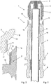
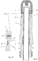
- plasma electrode 1 is constructed in two parts and consists of the front, replaceable electrode tip 2 and a rear electrode part 3, which is centered with a radially outer mounting flange 7 on the inside of a fastening body (electrode holder), not shown, and otherwise with a thread 8 can be screwed into such a fastening body.
- the entire plasma electrode 1 can be inserted sealed in a fastening body, not shown.
- a cooling tube 6 is arranged centrally, which engages with its front end in a receiving space 5 in the region of the electrode tip 2.
- An electrode core 4 is inserted in a bore of the electrode tip 2 is made of a highly-emissive material, such. A hafnium or zirconium material.
- the cooling of the plasma electrode takes place in such a way that a coolant flow is introduced into the interior 10 of the cooling tube 6, which is deflected in the region of the receiving space 5 in the electrode tip 2 and is then recirculated via the radially outer inner bore 9.
- connection portion 11 of the detachable connection consists of a screw thread.
- a screw thread 12 is formed.
- opposing and rectified conical surfaces 13, 14 are arranged on associated flanges of the electrode tip 2 and the electrode member 3 and that further engages a preferably encircling annular flange 15 on the electrode member 3 in an associated annular groove 16 and there centered.
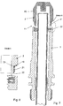
- FIG. 3 shows the composite structure of in FIG. 1 in the disassembled state shown plasma electrode, where it can be seen that the front, replaceable electrode tip 2 has a relatively short length 24 which is many times shorter than comparatively the non-replaceable electrode part 3 with a much greater length 25th
- the aspect ratios of these two lengths 24, 25 can range from 1: 1 to 1: 6.
- the electrode tip 2 is easily detachably mounted on the electrode-side electrode part 3 and therefore is easily replaceable when it is worn. It is kept short to keep material consumption low during replacement.
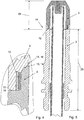
- FIGS. 5 to 8 show the kinematic reversal of a numeral 12 in the FIGS. 1 to 4 shown screw thread.
- the screw thread 12 from a on the inside of the electrode tip. 2 arranged internal thread, which is screwed into an associated, radially outwardly directed external thread on the electrode part 3.
- the threaded screw connection is sealed by a sealing ring 19 liquid-tight.
- FIGS. 7 and 8 show another embodiment of the screw, and the rest, that in the area of the electrode tip 2 also a key surface 20 may be provided for the attack of a suitable tool with which the electrode tip 2 can be unscrewed from the electrode part 3.
- an external thread is arranged on the rear side of the electrode tip 2, which cooperates with an internal thread in the interior of the electrode member 3 and the entire threaded connection is sealed liquid-tight by a sealing ring 19 which is inserted in an associated annular groove 23 on the vertical flange of the electrode tip 2 ,
- the external thread 21 on the electrode tip 2 thus cooperates with the internal thread 22 on the electrode part 3 as a screw thread 12.
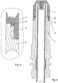
- FIGS. 9 to 12 show as a further embodiment, a plasma electrode in which the sealing ring 19 is integrally formed in the region of an outwardly open annular groove 23 at the foot of the vertical flange in the electrode part 3.
- the electrode tip 2 has an internal thread 22, which with the associated external thread 21 results in the sealed screw connection in the region of the connection part 11.
- FIGS. 11 and 12 show the in FIGS. 9 to 10 Threaded connection shown in the screwed state.
- FIG. 13 shows the state of the art according to the DE000069937323T2 and FIG. 2
- This document shows a screwed into a holder electrode 16 which is integrally formed and must be replaced when worn as an entire part.
- the electrode 16 is screwed with an upper screw thread 19 in a holder.
- the invention is now compared to this prior art is to form the known electrode 16 in two parts and form the front tip as easily replaceable electrode tip 2 and the rear part of the electrode 16 as an electrode part of the electrode body of the plasma electrode.
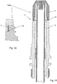
- FIG. 14 (Prior art according to the EP 1 765 046 B1 ) shows a replaceable, one-piece electrode 2 of considerable length, which corresponds in principle to the embodiment of the electrode according to the invention.
- the matching features are the upper thread and two annular grooves, in each of which an O-ring is inserted in order to screw the electrode sealed in an electrode holder can.
- the invention now provides that the in FIG. 14 shown electrode at the lowest point - is divided about the level of reference numeral 3 and there forms the replaceable electrode tip.
- the electrode tip thus formed only needs to be formed so long that the mounting surfaces to be arranged there and the electrode core can be arranged.
Landscapes
- Physics & Mathematics (AREA)
- Engineering & Computer Science (AREA)
- Plasma & Fusion (AREA)
- Spectroscopy & Molecular Physics (AREA)
- Plasma Technology (AREA)
- Arc Welding In General (AREA)
Description
- Die Erfindung betrifft eine Plasma-Elektrode für einen Plasma-Lichtbogenbrenner, bestehend aus einem Elektrodenkörper, der mindestens einen an der Elektrodenspitze angeordneten Elektrodenkern aufweist.
- Derartige Plasmaelektroden für die Verwendung bei Plasma-Lichtbogenbrenner sind in vielfältigen Ausführungsformen bekannt geworden.
- Als Beispiel wird auf die
EP 2 408 274 A2 , dieJP 2007-180028 A EP 1 765 046 B1 oder dieDE000069937323T2 verwiesen. - Hinsichtlich der Funktion und des Aufbaus eines Plasma-Lichtbogenbrenners wird auf die letztgenannten Druckschriften nach der
EP 1 765 046 B1 oderDE000069937323T2 verwiesen, deren Offenbarungsinhalt vollständig von dem Offenbarungsinhalt der vorliegenden Erfindung umfasst sein soll. - Der Verschleiß der Plasmaelektrode während des Betriebs ist beträchtlich. Der in die Vorderseite der Plasmaelektrode im Bereich der Elektrodenspitze in einer Bohrung eingesetzte Elektrodenkern erzeugt einen Plasma-Lichtbogen bei Temperaturen im Bereich zwischen 1.000 bis 2.000 Grad Celsius und besteht aus einem elektrisch leitfähigen, hoch-emissiven Material, z.B. Hafnium oder Zirkonium. Die Elektrodenspitze wird durch die hohen Brenntemperaturen stark beansprucht. Darüber hinaus entstehen Materialabtragungen am Elektrodenkern die sich als Materialspritzer auf der Elektrodenspitze und deren Umgebung ablagern, was zu einem unerwünschten Verschleiß und einer Begrenzung der Lebensdauer führt.
- Die
EP 1 633 172 A2 schlägt vor, den Elektrodenkern, der aus einem Hafnium-Material besteht, in einem aus Silber bestehenden Einsatzteil an der Elektrodenspitze zu halten. Dieses Einsatzteil (sieheFigur 7 ) ist in den vorderen Bereich der Elektrodenspitze eingelötet. - Es ist deshalb nicht möglich, die Elektrodenspitze als separates Teil auszutauschen. Vielmehr muss bei Verschleiß die gesamte Elektrode ausgetauscht werden, was mit hohen Kosten verbunden ist.
- Der Erfindung liegt deshalb die Aufgabe zugrunde, eine Plasma-Elektrode für einen Plasma-Lichtbogenbrenner der eingangs genannten Art so weiterzubilden, dass ein leichter und kostengünstiger Austausch der Elektrode bei Verschleiß möglich ist.
- Zur Lösung der gestellten Aufgabe ist die Erfindung durch die technische Lehre des Anspruches 1 gekennzeichnet.
- Die Erfindung geht davon aus, dass die aus einem hochwertigen Material (z. B. AG) bestehende Elektrode mindestens zweiteilig ausgebildet ist und nur noch der vordere, auswechselbare Spitzenteil aus einem hochwertigen Material (wie z.B. AG) besteht, während der hintere Elektrodenteil aus einem weniger hochwertigen Material, wie z.B. Cu oder einer Cu-Legierung oder einem vergleichbaren Material bestehen kann.
- Es wurde festgestellt, dass nur der Spitzenbereich der Elektrode mit dem dort eingesetzten Hafnium- oder Zirkonium-Kern einem wesentlichen Verschleiß unterliegt und gerade in diesem - unmittelbar an der Spitze liegenden - Teil Ausbrennspuren entstehen, die beim Stand der Technik zu einem Austausch der gesamten Elektrode zwangen.
- Die Zweiteilung der Elektrode nach der Erfindung ist vor allem bei Elektroden ab einer Gesamtlänge von mehr als 10-12 mm sinnvoll. In einem solchen Fall erfolgt die Zweiteilung derart, dass die auswechselbare Spitze eine Länge von z.B. 6 mm hat, während der verbleibende, rückwärtige Elektrodenteil die Restlänge ausmacht.
- Eine Zweiteilung ist aber besonders bei längeren Elektroden mit einer Gesamtlänge von z.B. 40 mm oder mehr. In diesem Fall ist es sinnvoll, die auswechselbare Spitze mit einer Länge von 10 mm auszubilden, während die Restlänge des Elektrodenteils aus einem unedleren Material bestehen kann. Demnach ist es ein Merkmal der Erfindung, dass die Plasma-Elektrode mindestens zweiteilig ausgebildet ist und mindestens aus der vorderen Elektrodenspitze und einem hinteren Elektrodenteil besteht und dass die Elektrodenspitze auswechselbar am Elektrodenteil gehalten ist.
- Die Erfindung sieht also eine mehrteilige Plasma-Elektrode vor, wobei der einfacheren Beschreibung wegen in der folgenden Beschreibung lediglich von zwei Teilen dieser Plasma-Elektrode ausgegangen wird, obwohl die Plasma-Elektrode auch aus mehr als zwei Teilen bestehen kann. Die Beschreibung einer zweiteiligen Plasmaelektrode soll deshalb den Schutzumfang der Erfindung nicht beschränken.
- Wesentliches Merkmal der Erfindung ist, dass bei einer zweiteiligen Ausbildung der Plasma-Elektrode nunmehr die Möglichkeit besteht, den vorderen Teil vom hinteren Teil zu lösen, weil diese beiden Teile bevorzugt lösbar miteinander verbunden sind.
- Auf diese Weise kann die vordere Elektrodenspitze mit dem dort eingebrachten Elektrodenkern von dem hinteren Elektrodenteil der Plasma-Elektrode entfernt werden, sofern ein Verschleiß an der Elektrodenspitze auftritt.
- Somit ist ein schnelles Auswechseln der Elektrodenspitze möglich, ohne dass damit die gesamte Plasma-Elektrode ausgewechselt werden müsste.
In einer bevorzugten Ausgestaltung der Erfindung ist die lösbare Verbindung zwischen den beiden Teilen der Plasma-Elektrode als Schraubverbindung, als Steckverbindung oder als kombinierte Schraub-Steckverbindung ausgebildet. - Im einfachsten Fall besteht die Schraubverbindung aus zwei ineinander greifenden Gewinden. An der Elektrodenspitze kann ein Innengewinde angeordnet sein, welches in ein zugeordnetes Außengewinde im Bereich des hinteren Elektrodenteils der Plasma-Elektrode einschraubbar ist.
- In einer anderen Ausgestaltung kann es auch vorgesehen sein, dass die Elektrodenspitze ein Außengewinde aufweist, welches auf ein zugeordnetes Innengewinde des hinteren Elektrodenteils der Plasma-Elektrode einschraubbar ist.
- In einer dritten Ausgestaltung kann es vorgesehen sein, dass statt der Schraubverbindung eine Steckverbindung verwendet wird, wie z. B. eine Bajonett-Steckverbindung, die durch eine Dreh-Steck-Bewegung gelöst und befestigt werden kann.
- In einer anderen Ausgestaltung ist es vorgesehen, dass die lösbare Verbindung zwischen den beiden Teilen der Plasma-Elektrode aus einer abgedichteten Flanschverbindung besteht, wobei zwei gegenüberliegend angeordnete Flansche an den beiden einander zugeordneten Teilen sich berühren und flüssigkeitsdicht gegeneinander abgedichtet sind. Eine solche FlanschVerbindung ist durch eine Überwurfmutter in Verbindung mit einem Gewinde am gegenüberliegenden Teil gesichert.
- Neben den genannten Steck- oder Schraubverbindungen oder Flanschverbindungen oder Kombinationen aus Steck-Schraub-Verbindungen mit Flanschverbindungen sind auch Klemmverbindungen vorgesehen. Eine solche Klemmverbindung ist z. B. eine Flanschverbindung, mit zwei abdichtend gegenüberliegend und aneinander anliegenden Flanschen, die von einem Exzenter-Klemmring auf gegenseitigem Anpressdruck abdichtend gehalten werden.
- Bei allen genannten Verbindungen ist es wichtig, dass, wenn es sich um eine wassergekühlte Plasma-Elektrode handelt, dann die genannte lösbare Verbindung zwischen den mindestens beiden Teilen der Plasma-Elektrode auch flüssigkeitsdicht ausgebildet ist.
- Mit der gegebenen technischen Lehre ergibt sich der Vorteil, dass auch hochwertige Materialien in materialschonender Weise verwendet werden können, denn es sind sämtliche Materialpaarungen zwischen dem Material der Elektrodenspitze und dem Material des hinteren Elektrodenteils der Plasma-Elektrode möglich.
- So kann es vorgesehen sein, dass der hintere Elektrodenteil der Plasma-Elektrode aus einem kostengünstigen Kupfer-Material oder einer Kupferlegierung besteht, während der vordere Teil der Elektrodenspitze, der dem Verschleiß unterworfen ist, aus einem Silbermaterial oder einer Silberlegierung besteht.
- Weil nur ein relativ kurzer Bereich der Plasma-Elektrode ausgetauscht werden muss, nämlich nur die kurz ausgebildete Elektrodenspitze, ergibt sich ein besonders materialschonender Einsatz teurer Materialien, wenn z. B. die Elektrodenspitze aus dem hochwertigen Silber oder einer Silberlegierung besteht.
- Bezüglich der Materialpaarungen zwischen dem Material des Elektrodenteils und der Elektrodenspitze gibt es folgende Kombinationen, wobei an erster Stelle stets das Material des Elektrodenteils steht und an zweiter Stelle das Material der Elektrodenspitze:
- Cu-Cu
- Cu-Ag
- Ag-Cu
- Ag-AG
- Die Verwendung von Silber als hochleitfähiges Material wurde nur beispielhaft angegeben. Es können selbstverständlich auch andere hochleitfähige, gut verarbeitbare Materialien verwendet werden, welche die Eigenschaften von Silber aufweisen. Insbesondere kommen hier Zinn-Legierungen in Betracht oder Kupfer-Zinn-Legierungen (Bronze).
- Die vorgenannten Materialien können in den gleichen vorgenannten Materialpaarungen eingesetzt werden, wie sie am Beispiel des Materials Ag vorstehend angegeben wurden.
- Die Erfindung ist nicht auf hohlzylindrische Plasma-Elektroden beschränkt, in deren Innenraum ein Kühlrohr angeordnet ist, mit dem ein Kühlmedium - bevorzugt Wasser - in den Innenraum der Plasmaelektrode eingeleitet, am vorderen Ende, in der Nähe der Elektrodenspitze umgeleitet wird, und danach wieder aus der Plasma-Elektrode herausgeleitet wird. Die Funktion einer derartigen wassergekühlten Plasma-Elektrode ergibt sich aus einer der vorgenannten Druckschriften.
- Die Erfindung beansprucht auch ungekühlte hohlzylindrische oder auch aus Vollmaterial bestehende Plasma-Elektroden, die mindestens zweiteilig sind und der vordere, dem Verschleiß unterworfene Teil leicht lösbar mit dem hinteren Teil verbunden ist.
- Der Erfindungsgegenstand der vorliegenden Erfindung ergibt sich nicht nur aus dem Gegenstand der einzelnen Patentansprüche, sondern auch aus der Kombination der einzelnen Patentansprüche untereinander.
- Alle in den Unterlagen, einschließlich der Zusammenfassung offenbarten Angaben und Merkmale, insbesondere die in den Zeichnungen dargestellte räumliche Ausbildung, werden als erfindungswesentlich beansprucht, soweit sie einzeln oder in Kombination gegenüber dem Stand der Technik neu sind.
- Im Folgenden wird die Erfindung anhand von mehrere Ausführungswege darstellenden Zeichnungen näher erläutert. Hierbei gehen aus den Zeichnungen und ihrer Beschreibung weitere erfindungswesentliche Merkmale und Vorteile der Erfindung hervor.
- Es zeigen:
-
Figur 1 : Schnitt durch eine erste Ausführungsform einer zweiteiligen Plasma-Elektrode in zerlegtem Zustand -
Figur 2 : Detailschnitt durch die Schraubverbindung nachFigur 1 -
Figur 3 : Schnitt durch die Plasma-Elektrode nachFigur 1 im zusammengesetzten Zustand -
Figur 4 : die Schraubverbindung nachFigur 2 im zusammengesetzten Zustand -
Figur 5 : Schnitt durch eine zweite Ausführungsform einer zweiteiligen Plasma-Elektrode -
Figur 6 : Schnitt durch die abgedichtete Schraubverbindung -
Figur 7 : die Plasma-Elektrode nachFigur 5 im zerlegten Zustand -
Figur 8 : die Gewindeschraubverbindung nachFigur 7 in Detaildarstellung -
Figur 9 : eine dritte Ausführungsform einer Plasma-Elektrode in zerlegtem Zustand -
Figur 10 : ein Detail der Gewindeschraubverbindung nachFigur 9 im zerlegten Zustand -
Figur 11 : die Plasma-Elektrode nachFigur 9 im zusammengesetzten Zustand -
Figur 12 : die Gewindeschraubverbindung nachFigur 10 im eingeschraubten Zustand -
Figur 13 zeigt einen Plasma-Lichtbogenbrenner nach dem Stand der Technik gemäßDE000069937323T2 . -
Figur 14 : Plasma-Lichtbogenbrenner nach dem Stand der Technik gemäß derEP 1 765 046 B1 . - Die in
Figur 1 dargestellte Plasma-Elektrode 1 ist zweiteilig aufgebaut und besteht aus der vorderen, auswechselbaren Elektrodenspitze 2 und einem hinteren Elektrodenteil 3, welches sich mit einem radial außen liegenden Befestigungsflansch 7 an der Innenseite eines nicht näher dargestellten Befestigungskörpers (Elektrodenhalter) zentriert und im Übrigen mit einem Gewinde 8 in einen solchen Befestigungskörper eingeschraubt werden kann. - Statt einer Schraubbefestigung über das Gewinde 8 kann die gesamte Plasma-Elektrode 1 auch in einen nicht näher dargestellten Befestigungskörper abgedichtet eingesteckt werden. Im Innenraum 10 der Plasma-Elektrode 1 ist ein Kühlrohr 6 zentrisch angeordnet, welches mit seinem vorderen Ende in einen Aufnahmeraum 5 im Bereich der Elektrodenspitze 2 eingreift.
- Ein Elektrodenkern 4 ist in einer Bohrung der Elektrodenspitze 2 ist aus einem hoch-emissiven Material eingebracht, wie z. B. einem Hafnium- oder Zirkoniummaterial.
- Die Kühlung der Plasma-Elektrode erfolgt dergestalt, dass ein Kühlmittelstrom in den Innenraum 10 des Kühlrohrs 6 eingeleitet wird, der im Bereich des Aufnahmeraums 5 in der Elektrodenspitze 2 umgelenkt wird und dann über die radial außen liegende Innenbohrung 9 wieder zurückgeführt wird.
- Wichtig ist, dass die beiden Teile (Elektrodenspitze 2 und Elektrodenteil 3) lösbar miteinander verbunden sind. Im gezeigten Ausführungsbeispiel nach
Figur 2 besteht der Verbindungsbereich 11 der lösbaren Verbindung aus einem Schraubgewinde. Hierbei weist die Elektrodenspitze 2 an einem vertikalen Flansch ein Außengewinde auf, welches in ein zugeordnetes Innengewinde an einem gleichfalls am Elektrodenteil 3 angeformten Flansch angreift. Dadurch wird ein Schraubgewinde 12 gebildet. - Zur selbsttätigen Zentrierung dieses Schraubgewindes ist es vorgesehen, dass einander gegenüberliegende und gleichgerichtete Konusflächen 13, 14 an zugeordneten Flanschen der Elektrodenspitze 2 und des Elektrodenteils 3 angeordnet sind und dass ferner ein bevorzugt ringsumlaufender Ringflansch 15 am Elektrodenteil 3 in eine zugeordnete Ringnut 16 eingreift und sich dort zentriert.
- Durch das Eingreifen von Ringflansch 15 und Ringnut 16 in Verbindung mit den schräg gerichteten Konusflächen 13, 14 kommt es zu einer selbsttätigen Zentrierung der Schraubverbindung.
- Zusätzlich können bei vollständiger Verfestigung der Schraubverbindung (siehe
Figur 4 ) die horizontalen Ansätze 17, 18 abdichtend aufeinander liegen. In diesem Bereich können zusätzliche Abdichtmittel wie z. B. ein Dichtring 19 angeordnet sein. - Die
Figur 3 zeigt den zusammengesetzten Aufbau der inFigur 1 im zerlegten Zustand gezeigten Plasma-Elektrode, wo erkennbar ist, dass die vordere, auswechselbare Elektrodenspitze 2 eine relativ kurze Länge 24 aufweist, die um ein vielfaches kürzer ist als vergleichsweise der nicht auswechselbare Elektrodenteil 3 mit einer wesentlich größeren Länge 25. - Die Längenverhältnisse dieser beiden Längen 24, 25 können sich im Bereich zwischen 1 : 1 bis 1 : 6 bewegen.
- Wichtig ist bei allen Ausführungsbeispielen, dass die Elektrodenspitze 2 leicht lösbar auf dem elektrodenseitigen Elektrodenteil 3 befestigt ist und deshalb leicht austauschbar ist, wenn sie verschlissen ist. Sie ist kurz gehalten, um den Materialverbrauch beim Austausch niedrig zu halten.
- Die
Figuren 5 bis 8 zeigen die kinematische Umkehrung eines mit Ziffer 12 in denFiguren 1 bis 4 dargestellten Schraubgewindes. Dort ist erkennbar, dass das Schraubgewinde 12 aus einem an der Innenseite der Elektrodenspitze 2 angeordneten Innengewinde besteht, welches in ein zugeordnetes, radial nach außen gerichtetes Außengewinde am Elektrodenteil 3 einschraubbar ist. - Die Gewindeschraubverbindung ist durch einen Dichtring 19 flüssigkeitsdicht abgedichtet.
- Es kann noch ein weiterer Dichtring 19 im Bereich der einander zugewandten Ansätze 17, 18 angeordnet sein.
- Die
Figuren 7 und 8 zeigen eine andere Ausführungsform der Schraubverbindung, und im Übrigen, dass im Bereich der Elektrodenspitze 2 auch noch eine Schlüsselfläche 20 für den Angriff eines geeigneten Werkzeuges vorgesehen sein kann, mit dem die Elektrodenspitze 2 von dem Elektrodenteil 3 abgeschraubt werden kann. - Auch hier ist an der hinteren Seite der Elektrodenspitze 2 ein Außengewinde angeordnet, welches mit einem Innengewinde im Innenraum des Elektrodenteils 3 zusammenwirkt und die gesamte Gewindeschraubverbindung durch einen Dichtring 19 flüssigkeitsdicht abgedichtet ist, der in einer zugeordneten Ringnut 23 am vertikalen Flansch der Elektrodenspitze 2 eingesetzt ist.
- Das Außengewinde 21 an der Elektrodenspitze 2 wirkt also mit dem Innengewinde 22 am Elektrodenteil 3 als Schraubgewinde 12 zusammen.
- Die
Figuren 9 bis 12 zeigen als weiteres Ausführungsbeispiel eine Plasma-Elektrode, bei der der Dichtring 19 im Bereich einer nach außen geöffneten Ringnut 23 am Fuß des vertikalen Flansches im Elektrodenteil 3 angeformt ist. - Hier weist die Elektrodenspitze 2 ein Innengewinde 22 auf, welches mit dem zugeordneten Außengewinde 21 die abgedichtete Schraubverbindung im Bereich des Verbindungsteils 11 ergibt.
- Die
Figuren 11 und 12 zeigen die inFigur 9 bis 10 gezeigte Gewindeschraubverbindung im eingeschraubten Zustand. -
Fig. 13 zeigt den Stand der Technik nach derDE000069937323T2 undFigur 2 dieser Druckschrift zeigt eine in einen Halter einschraubbare Elektrode 16, die einteilig ausgebildet ist und bei Verschleiß als gesamtes Teil ausgetauscht werden muß. Zu diesem Zweck ist die Elektrode 16 mit einem oberen Schraubgewinde 19 in einen Halter eingeschraubt. - Die Erfindung besteht nun im Vergleich zu diesem Stand der Technik darin, die bekannte Elektrode 16 zweiteilig auszubilden und die vordere Spitze als leicht auswechselbare Elektrodenspitze 2 und den hinteren Teil der Elektrode 16 als Elektrodenteil des Elektrodenkörpers der Plasma-Elektrode auszubilden.
- Die Unterteilung würde nach der Erfindung in Höhe des untersten Randes der in
Figur 2 dieser Druckschrift dargestellten Elektrode 16 erfolgen. Der sich an den Sechskant anschließende, untere Bereich der Elektrode ist somit gemäß der Erfindung auswechselbar ausgebildet und bildet eine dort lösbar gehaltene, auswechselbare Elektrodenspitze. Dies ist durch die gestrichelte Linie a gekennzeichnet. Eine andere Möglichkeit besteht in der Trennung der beiden Elektrodenteile gemäß der oberen Linie b. - Damit muss bei einem Verschleiß der Elektrode 16 nun mehr der vordere Spitzenbereich der Elektrode (gekennzeichnet durch die Linien a oder b), der sich in unmittelbarer Nachbarschaft zum Kern 29 befindet, ausgetauscht werden, der hintere Teil der Plasma-Elektrode 16 muss deshalb nicht mehr ausgetauscht werden.
- Die
Figur 14 (Stand der Technik nach derEP 1 765 046 B1 ) zeigt eine auswechselbare, einteilige Elektrode 2 beträchtlicher Länge, die prinzipiell der Ausführung der Elektrode nach der Erfindung entspricht. Die übereinstimmenden Merkmale sind das obere Einschraubgewinde und zwei Ringnuten, in welche jeweils ein O-Ring eingelegt ist, um die Elektrode in einen Elektrodenhalter abgedichtet einschrauben zu können. - Die Erfindung sieht nun vor, dass die in
Figur 14 gezeigte Elektrode an der untersten Spitze - etwa in Höhe des Bezugszeichens 3 unterteilt ist und dort die auswechselbare Elektrodenspitze ausbildet. Die so gebildete Elektrodenspitze muss nur so lang ausgebildet sein, dass die dort anzuordnenden Befestigungsflächen und der Elektrodenkern angeordnet werden können. -
- 1
- Plasma-Elektrode
- 2
- Elektrodenspitze
- 3
- Elektrodenteil
- 4
- Elektrodenkern
- 5
- Aufnahmeraum
- 6
- Kühlrohr
- 7
- Befestigungsflansch
- 8
- Gewinde
- 9
- Innenbohrung
- 10
- Innenraum
- 11
- Verbindungsteil
- 12
- Schraubgewinde
- 13
- Konusflächen
- 14
- Konusflächen
- 15
- Ringflansch
- 16
- Ringnut
- 17
- Ansatz
- 18
- Ansatz
- 19
- Dichtring
- 20
- Schlüsselfläche
- 21
- Außengewinde
- 22
- Innengewinde
- 23
- Ringnut (für 19)
- 24
- Länge (von 2)
- 25
- Länge (von 3)
Claims (10)
- Plasma-Elektrode (1) für einen Plasma-Lichtbogenbrenner bestehend aus einem Elektrodenkörper, der aus einer vorderen Elektrodenspitze (2) mit einem dort angeordneten Elektrodenkern (4) und aus dem sich daran anschliessenden rohrförmigen Elektrodenteil besteht, wobei das Elektrodenteil einen Befestigungsflansch (7) und ein Schraubgewinde (8) oder eine Steckfassung zur Festlegung in einem Elektrodenhalter aufweist,
dadurch gekennzeichnet, dass die Elektrodenspitze mindestens zweiteilig ausgebildet ist und aus einer vorderen Elektrodenspitze (2) und einer hinteren Elektrodenspitze (3) besteht, dass die vordere Elektrodenspitze (2) auswechselbar an der hinteren Elektrodenspitze (3) gehalten ist und dass eine lösbare Verbindung zwischen der vorderen Elektrodenspitze (2) und der sich daran anschliessenden hinteren Elektrodenspitze (3) angeordnet ist. - Plasma-Elektrode nach Anspruch 1, dadurch gekennzeichnet, dass die lösbare Verbindung zwischen der vorderen Elektrodenspitze (2) und der hinteren Elektrodenspitze (3) der Plasma-Elektrode (1) als abgedichtete Schraub- oder Steck- oder Schraub-Steckverbindung (11) ausgebildet ist.
- Plasma-Elektrode nach Anspruch 2, dadurch gekennzeichnet, dass die abgedichtete Schraub- oder Steck- oder Schraub-Steckverbindung (11) selbst zentrierend ausgebildet ist.
- Plasma-Elektrode nach einem der Ansprüche 1 bis 3, dadurch gekennzeichnet, dass das Längenverhältnis (24, 25) zwischen der vorderen, auswechselbaren Elektrodenspitze (2) und der hinteren Elektrodenspitze (3) im Bereich zwischen 1:6 bis 1:1 liegt.
- Plasma-Elektrode nach einem der Ansprüche 1 bis 4, dadurch gekennzeichnet, dass das Material der vorderen Elektrodenspitze (2) und der hinteren Elektrodenspitze (3) gleichartig ist.
- Plasma-Elektrode nach einem der Ansprüche 1 bis 4, dadurch gekennzeichnet, dass das Material der vorderen Elektrodenspitze (2) und der hinteren Elektrodenspitze (3) ungleichartig ist.
- Plasma-Elektrode nach einem der Ansprüche 1 bis 6, dadurch gekennzeichnet, dass die lösbare Verbindung zwischen der vorderen Elektrodenspitze (2) und der hinteren Elektrodenspitze (3) der Plasma-Elektrode (1) als abgedichtete Flanschverbindung mit einer Überwurfmutter zur Befestigung und Sicherung der Flanschverbindung ausgebildet ist.
- Plasma-Elektrode nach einem der Ansprüche 1 bis 7, dadurch gekennzeichnet, dass die Plasma-Elektrode (1) als hohlzylindrischer Metallkörper ausgebildet ist, in dessen Innenraum (10) ein Kühlrohr (6) angeordnet ist.
- Plasma-Elektrode nach einem der Ansprüche 1 bis 7, dadurch gekennzeichnet, dass am Außenumfang der hinteren Elektrodenspitze (3) Schraub- und/oder Steckansätze zur Halterung der Plasma-Elektrode (1) in einem Brennerkörper angeordnet sind.
- Plasma-Elektrode nach einem der Ansprüche 1 bis 9, dadurch gekennzeichnet, dass mindestens die vordere Elektrodenspitze (2) aus einem Vollmaterial besteht.
Priority Applications (1)
| Application Number | Priority Date | Filing Date | Title |
|---|---|---|---|
| EP13714852.4A EP2829162B1 (de) | 2012-03-23 | 2013-03-22 | Plasmaelektrode für einen plasma-lichtbogenbrenner mit auswechselbarer elektrodenspitze |
Applications Claiming Priority (3)
| Application Number | Priority Date | Filing Date | Title |
|---|---|---|---|
| EP12002077.1A EP2642832A1 (de) | 2012-03-23 | 2012-03-23 | Plasma-Elektrode für einen Plasmalichtbogenbrenner mit auswechselbarer Elektrodenspitze |
| EP13714852.4A EP2829162B1 (de) | 2012-03-23 | 2013-03-22 | Plasmaelektrode für einen plasma-lichtbogenbrenner mit auswechselbarer elektrodenspitze |
| PCT/EP2013/000876 WO2013139484A1 (de) | 2012-03-23 | 2013-03-22 | Plasmaelektrode für einen plasma-lichtbogenbrenner mit auswechselbarer elektrodenspitze |
Publications (2)
| Publication Number | Publication Date |
|---|---|
| EP2829162A1 EP2829162A1 (de) | 2015-01-28 |
| EP2829162B1 true EP2829162B1 (de) | 2017-05-17 |
Family
ID=48050654
Family Applications (2)
| Application Number | Title | Priority Date | Filing Date |
|---|---|---|---|
| EP12002077.1A Withdrawn EP2642832A1 (de) | 2012-03-23 | 2012-03-23 | Plasma-Elektrode für einen Plasmalichtbogenbrenner mit auswechselbarer Elektrodenspitze |
| EP13714852.4A Not-in-force EP2829162B1 (de) | 2012-03-23 | 2013-03-22 | Plasmaelektrode für einen plasma-lichtbogenbrenner mit auswechselbarer elektrodenspitze |
Family Applications Before (1)
| Application Number | Title | Priority Date | Filing Date |
|---|---|---|---|
| EP12002077.1A Withdrawn EP2642832A1 (de) | 2012-03-23 | 2012-03-23 | Plasma-Elektrode für einen Plasmalichtbogenbrenner mit auswechselbarer Elektrodenspitze |
Country Status (3)
| Country | Link |
|---|---|
| US (1) | US9736916B2 (de) |
| EP (2) | EP2642832A1 (de) |
| WO (1) | WO2013139484A1 (de) |
Families Citing this family (3)
| Publication number | Priority date | Publication date | Assignee | Title |
|---|---|---|---|---|
| CN109079294B (zh) * | 2018-10-31 | 2023-08-11 | 浙江巨化装备制造有限公司 | 全自动管板焊机枪头连续自动钨棒更换装置及更换方法 |
| CN113950869A (zh) * | 2019-04-04 | 2022-01-18 | 海别得公司 | 用于液体冷却的等离子弧炬的可调节长度消耗件 |
| CZ308703B6 (cs) | 2020-02-05 | 2021-03-03 | B&Bartoni, spol. s r.o. | Sestava elektrody pro plazmový obloukový hořák se zlepšeným přenosem elektrického proudu |
Family Cites Families (12)
| Publication number | Priority date | Publication date | Assignee | Title |
|---|---|---|---|---|
| US5216221A (en) * | 1992-01-17 | 1993-06-01 | Esab Welding Products, Inc. | Plasma arc torch power disabling mechanism |
| US5440094A (en) * | 1994-04-07 | 1995-08-08 | Douglas G. Carroll | Plasma arc torch with removable anode ring |
| US6020572A (en) * | 1998-08-12 | 2000-02-01 | The Esab Group, Inc. | Electrode for plasma arc torch and method of making same |
| US6498316B1 (en) * | 1999-10-25 | 2002-12-24 | Thermal Dynamics Corporation | Plasma torch and method for underwater cutting |
| US7081597B2 (en) * | 2004-09-03 | 2006-07-25 | The Esab Group, Inc. | Electrode and electrode holder with threaded connection |
| US8101882B2 (en) | 2005-09-07 | 2012-01-24 | Hypertherm, Inc. | Plasma torch electrode with improved insert configurations |
| US7256366B2 (en) | 2005-12-21 | 2007-08-14 | The Esab Group, Inc. | Plasma arc torch, and methods of assembling and disassembling a plasma arc torch |
| US9662747B2 (en) * | 2006-09-13 | 2017-05-30 | Hypertherm, Inc. | Composite consumables for a plasma arc torch |
| DE102008062731C5 (de) * | 2008-12-18 | 2012-06-14 | Kjellberg Finsterwalde Plasma Und Maschinen Gmbh | Elektrode für einen Plasmabrenner |
| DE102009016932B4 (de) * | 2009-04-08 | 2013-06-20 | Kjellberg Finsterwalde Plasma Und Maschinen Gmbh | Kühlrohre und Elektrodenaufnahme für einen Lichtbogenplasmabrenner sowie Anordnungen aus denselben und Lichtbogenplasmabrenner mit denselben |
| US8884179B2 (en) | 2010-07-16 | 2014-11-11 | Hypertherm, Inc. | Torch flow regulation using nozzle features |
| US9211603B2 (en) * | 2012-01-31 | 2015-12-15 | The Esab Group, Inc. | Plasma gouging torch and angled nozzle therefor |
-
2012
- 2012-03-23 EP EP12002077.1A patent/EP2642832A1/de not_active Withdrawn
-
2013
- 2013-03-22 EP EP13714852.4A patent/EP2829162B1/de not_active Not-in-force
- 2013-03-22 WO PCT/EP2013/000876 patent/WO2013139484A1/de not_active Ceased
- 2013-03-22 US US14/361,903 patent/US9736916B2/en not_active Expired - Fee Related
Also Published As
| Publication number | Publication date |
|---|---|
| EP2642832A1 (de) | 2013-09-25 |
| WO2013139484A4 (de) | 2013-11-21 |
| US9736916B2 (en) | 2017-08-15 |
| EP2829162A1 (de) | 2015-01-28 |
| WO2013139484A1 (de) | 2013-09-26 |
| US20140291303A1 (en) | 2014-10-02 |
Similar Documents
| Publication | Publication Date | Title |
|---|---|---|
| DE60018968T2 (de) | Plasma-Lichtbogenbrenner, Plasmabrennerkathode und Plasmabrennerelektrode | |
| DE69630700T2 (de) | Schweisskontaktspitze | |
| DE2706559C2 (de) | Plasmaflammspritzpistole | |
| DE102008052458A1 (de) | Brenner und Kontaktspitze für Gasmetallbogenschweißen | |
| DE202013102979U1 (de) | Schweißbrenner für das Lichtbogen-Schutzgasschweißen und Kontaktrohr für einen solchen Schweißbrenner | |
| DE102016010341B4 (de) | Plasmabrenner und komponenten des plasmabrenners | |
| EP0372111B1 (de) | Elektrode für einen Glasschmelzofen | |
| DE202009018173U1 (de) | Düsenschutzkappe und Düsenschutzkappenhalter sowie Lichtbogenplasmabrenner mit derselben und/oder demselben | |
| DE202008011356U1 (de) | Wolfram- Inertgas- Schweißbrenner | |
| EP2226899A1 (de) | Vorrichtung zum Verbinden von zwei elektrischen Leitern | |
| DE202015106360U1 (de) | Fräserkopfeinheit, Fräserschaft und Aufschraubfräser | |
| EP2829162B1 (de) | Plasmaelektrode für einen plasma-lichtbogenbrenner mit auswechselbarer elektrodenspitze | |
| DE102012213453A1 (de) | Brenner für das Wolfram-Inertgas-Schweißen | |
| EP2667689B1 (de) | Elektrode für Plasmaschneidbrenner sowie deren Verwendung | |
| DE69621360T2 (de) | Kohlenstoffelektrode | |
| DE102009059108A1 (de) | Elektrode mit Kühlrohr für eine Plasmaschneidvorrichtung | |
| EP2663167B1 (de) | Kühlrohr für einen Plasma-Lichtbogenbrenner und Abstandshalter | |
| EP1675144A1 (de) | Hochleistungsschalter mit abbrandfester Kurzschlusstromführung | |
| DE102014202435A1 (de) | Modular ausgebildeter Schweißelektrodenhalter | |
| DE10338774B4 (de) | Schweißbrennerelement, Bauteilkombination, Schweißbrenner und Schweißsystem | |
| EP1692922B1 (de) | Plasmaspritzvorrichtung | |
| DE10322116B3 (de) | Kontaktdüse für Flachdraht-Schweißen | |
| DE2642411C2 (de) | Kabelschuh für Elektrokabel | |
| DE1048651B (de) | ||
| DE102013214551B4 (de) | Drahtdüse und Verfahren zum Laserfügen mit Zusatzdraht mit taktiler Drahtführung |
Legal Events
| Date | Code | Title | Description |
|---|---|---|---|
| PUAI | Public reference made under article 153(3) epc to a published international application that has entered the european phase |
Free format text: ORIGINAL CODE: 0009012 |
|
| 17P | Request for examination filed |
Effective date: 20141023 |
|
| AK | Designated contracting states |
Kind code of ref document: A1 Designated state(s): AL AT BE BG CH CY CZ DE DK EE ES FI FR GB GR HR HU IE IS IT LI LT LU LV MC MK MT NL NO PL PT RO RS SE SI SK SM TR |
|
| AX | Request for extension of the european patent |
Extension state: BA ME |
|
| DAX | Request for extension of the european patent (deleted) | ||
| 17Q | First examination report despatched |
Effective date: 20160318 |
|
| GRAP | Despatch of communication of intention to grant a patent |
Free format text: ORIGINAL CODE: EPIDOSNIGR1 |
|
| STAA | Information on the status of an ep patent application or granted ep patent |
Free format text: STATUS: GRANT OF PATENT IS INTENDED |
|
| INTG | Intention to grant announced |
Effective date: 20161206 |
|
| GRAS | Grant fee paid |
Free format text: ORIGINAL CODE: EPIDOSNIGR3 |
|
| GRAA | (expected) grant |
Free format text: ORIGINAL CODE: 0009210 |
|
| STAA | Information on the status of an ep patent application or granted ep patent |
Free format text: STATUS: THE PATENT HAS BEEN GRANTED |
|
| RAP1 | Party data changed (applicant data changed or rights of an application transferred) |
Owner name: HOLLBERG, MANFRED |
|
| RIN1 | Information on inventor provided before grant (corrected) |
Inventor name: HOLLBERG, MANFRED |
|
| AK | Designated contracting states |
Kind code of ref document: B1 Designated state(s): AL AT BE BG CH CY CZ DE DK EE ES FI FR GB GR HR HU IE IS IT LI LT LU LV MC MK MT NL NO PL PT RO RS SE SI SK SM TR |
|
| REG | Reference to a national code |
Ref country code: GB Ref legal event code: FG4D Free format text: NOT ENGLISH |
|
| REG | Reference to a national code |
Ref country code: CH Ref legal event code: EP |
|
| REG | Reference to a national code |
Ref country code: IE Ref legal event code: FG4D Free format text: LANGUAGE OF EP DOCUMENT: GERMAN |
|
| REG | Reference to a national code |
Ref country code: AT Ref legal event code: REF Ref document number: 895523 Country of ref document: AT Kind code of ref document: T Effective date: 20170615 |
|
| REG | Reference to a national code |
Ref country code: DE Ref legal event code: R096 Ref document number: 502013007285 Country of ref document: DE |
|
| REG | Reference to a national code |
Ref country code: NL Ref legal event code: MP Effective date: 20170517 |
|
| REG | Reference to a national code |
Ref country code: LT Ref legal event code: MG4D |
|
| PG25 | Lapsed in a contracting state [announced via postgrant information from national office to epo] |
Ref country code: NO Free format text: LAPSE BECAUSE OF FAILURE TO SUBMIT A TRANSLATION OF THE DESCRIPTION OR TO PAY THE FEE WITHIN THE PRESCRIBED TIME-LIMIT Effective date: 20170817 Ref country code: ES Free format text: LAPSE BECAUSE OF FAILURE TO SUBMIT A TRANSLATION OF THE DESCRIPTION OR TO PAY THE FEE WITHIN THE PRESCRIBED TIME-LIMIT Effective date: 20170517 Ref country code: FI Free format text: LAPSE BECAUSE OF FAILURE TO SUBMIT A TRANSLATION OF THE DESCRIPTION OR TO PAY THE FEE WITHIN THE PRESCRIBED TIME-LIMIT Effective date: 20170517 Ref country code: LT Free format text: LAPSE BECAUSE OF FAILURE TO SUBMIT A TRANSLATION OF THE DESCRIPTION OR TO PAY THE FEE WITHIN THE PRESCRIBED TIME-LIMIT Effective date: 20170517 Ref country code: HR Free format text: LAPSE BECAUSE OF FAILURE TO SUBMIT A TRANSLATION OF THE DESCRIPTION OR TO PAY THE FEE WITHIN THE PRESCRIBED TIME-LIMIT Effective date: 20170517 Ref country code: GR Free format text: LAPSE BECAUSE OF FAILURE TO SUBMIT A TRANSLATION OF THE DESCRIPTION OR TO PAY THE FEE WITHIN THE PRESCRIBED TIME-LIMIT Effective date: 20170818 |
|
| PG25 | Lapsed in a contracting state [announced via postgrant information from national office to epo] |
Ref country code: SE Free format text: LAPSE BECAUSE OF FAILURE TO SUBMIT A TRANSLATION OF THE DESCRIPTION OR TO PAY THE FEE WITHIN THE PRESCRIBED TIME-LIMIT Effective date: 20170517 Ref country code: LV Free format text: LAPSE BECAUSE OF FAILURE TO SUBMIT A TRANSLATION OF THE DESCRIPTION OR TO PAY THE FEE WITHIN THE PRESCRIBED TIME-LIMIT Effective date: 20170517 Ref country code: BG Free format text: LAPSE BECAUSE OF FAILURE TO SUBMIT A TRANSLATION OF THE DESCRIPTION OR TO PAY THE FEE WITHIN THE PRESCRIBED TIME-LIMIT Effective date: 20170817 Ref country code: RS Free format text: LAPSE BECAUSE OF FAILURE TO SUBMIT A TRANSLATION OF THE DESCRIPTION OR TO PAY THE FEE WITHIN THE PRESCRIBED TIME-LIMIT Effective date: 20170517 Ref country code: PL Free format text: LAPSE BECAUSE OF FAILURE TO SUBMIT A TRANSLATION OF THE DESCRIPTION OR TO PAY THE FEE WITHIN THE PRESCRIBED TIME-LIMIT Effective date: 20170517 Ref country code: IS Free format text: LAPSE BECAUSE OF FAILURE TO SUBMIT A TRANSLATION OF THE DESCRIPTION OR TO PAY THE FEE WITHIN THE PRESCRIBED TIME-LIMIT Effective date: 20170917 Ref country code: NL Free format text: LAPSE BECAUSE OF FAILURE TO SUBMIT A TRANSLATION OF THE DESCRIPTION OR TO PAY THE FEE WITHIN THE PRESCRIBED TIME-LIMIT Effective date: 20170517 |
|
| PG25 | Lapsed in a contracting state [announced via postgrant information from national office to epo] |
Ref country code: RO Free format text: LAPSE BECAUSE OF FAILURE TO SUBMIT A TRANSLATION OF THE DESCRIPTION OR TO PAY THE FEE WITHIN THE PRESCRIBED TIME-LIMIT Effective date: 20170517 Ref country code: CZ Free format text: LAPSE BECAUSE OF FAILURE TO SUBMIT A TRANSLATION OF THE DESCRIPTION OR TO PAY THE FEE WITHIN THE PRESCRIBED TIME-LIMIT Effective date: 20170517 Ref country code: SK Free format text: LAPSE BECAUSE OF FAILURE TO SUBMIT A TRANSLATION OF THE DESCRIPTION OR TO PAY THE FEE WITHIN THE PRESCRIBED TIME-LIMIT Effective date: 20170517 Ref country code: EE Free format text: LAPSE BECAUSE OF FAILURE TO SUBMIT A TRANSLATION OF THE DESCRIPTION OR TO PAY THE FEE WITHIN THE PRESCRIBED TIME-LIMIT Effective date: 20170517 Ref country code: DK Free format text: LAPSE BECAUSE OF FAILURE TO SUBMIT A TRANSLATION OF THE DESCRIPTION OR TO PAY THE FEE WITHIN THE PRESCRIBED TIME-LIMIT Effective date: 20170517 |
|
| REG | Reference to a national code |
Ref country code: DE Ref legal event code: R097 Ref document number: 502013007285 Country of ref document: DE |
|
| PG25 | Lapsed in a contracting state [announced via postgrant information from national office to epo] |
Ref country code: SM Free format text: LAPSE BECAUSE OF FAILURE TO SUBMIT A TRANSLATION OF THE DESCRIPTION OR TO PAY THE FEE WITHIN THE PRESCRIBED TIME-LIMIT Effective date: 20170517 Ref country code: IT Free format text: LAPSE BECAUSE OF FAILURE TO SUBMIT A TRANSLATION OF THE DESCRIPTION OR TO PAY THE FEE WITHIN THE PRESCRIBED TIME-LIMIT Effective date: 20170517 |
|
| PLBE | No opposition filed within time limit |
Free format text: ORIGINAL CODE: 0009261 |
|
| STAA | Information on the status of an ep patent application or granted ep patent |
Free format text: STATUS: NO OPPOSITION FILED WITHIN TIME LIMIT |
|
| 26N | No opposition filed |
Effective date: 20180220 |
|
| PG25 | Lapsed in a contracting state [announced via postgrant information from national office to epo] |
Ref country code: SI Free format text: LAPSE BECAUSE OF FAILURE TO SUBMIT A TRANSLATION OF THE DESCRIPTION OR TO PAY THE FEE WITHIN THE PRESCRIBED TIME-LIMIT Effective date: 20170517 |
|
| PG25 | Lapsed in a contracting state [announced via postgrant information from national office to epo] |
Ref country code: MT Free format text: LAPSE BECAUSE OF FAILURE TO SUBMIT A TRANSLATION OF THE DESCRIPTION OR TO PAY THE FEE WITHIN THE PRESCRIBED TIME-LIMIT Effective date: 20170517 |
|
| REG | Reference to a national code |
Ref country code: CH Ref legal event code: PL |
|
| GBPC | Gb: european patent ceased through non-payment of renewal fee |
Effective date: 20180322 |
|
| PG25 | Lapsed in a contracting state [announced via postgrant information from national office to epo] |
Ref country code: MC Free format text: LAPSE BECAUSE OF FAILURE TO SUBMIT A TRANSLATION OF THE DESCRIPTION OR TO PAY THE FEE WITHIN THE PRESCRIBED TIME-LIMIT Effective date: 20170517 |
|
| REG | Reference to a national code |
Ref country code: BE Ref legal event code: MM Effective date: 20180331 |
|
| REG | Reference to a national code |
Ref country code: IE Ref legal event code: MM4A |
|
| PG25 | Lapsed in a contracting state [announced via postgrant information from national office to epo] |
Ref country code: LU Free format text: LAPSE BECAUSE OF NON-PAYMENT OF DUE FEES Effective date: 20180322 |
|
| PG25 | Lapsed in a contracting state [announced via postgrant information from national office to epo] |
Ref country code: IE Free format text: LAPSE BECAUSE OF NON-PAYMENT OF DUE FEES Effective date: 20180322 |
|
| PG25 | Lapsed in a contracting state [announced via postgrant information from national office to epo] |
Ref country code: LI Free format text: LAPSE BECAUSE OF NON-PAYMENT OF DUE FEES Effective date: 20180331 Ref country code: BE Free format text: LAPSE BECAUSE OF NON-PAYMENT OF DUE FEES Effective date: 20180331 Ref country code: CH Free format text: LAPSE BECAUSE OF NON-PAYMENT OF DUE FEES Effective date: 20180331 Ref country code: GB Free format text: LAPSE BECAUSE OF NON-PAYMENT OF DUE FEES Effective date: 20180322 |
|
| PG25 | Lapsed in a contracting state [announced via postgrant information from national office to epo] |
Ref country code: FR Free format text: LAPSE BECAUSE OF NON-PAYMENT OF DUE FEES Effective date: 20180331 |
|
| REG | Reference to a national code |
Ref country code: AT Ref legal event code: MM01 Ref document number: 895523 Country of ref document: AT Kind code of ref document: T Effective date: 20180322 |
|
| PG25 | Lapsed in a contracting state [announced via postgrant information from national office to epo] |
Ref country code: AT Free format text: LAPSE BECAUSE OF NON-PAYMENT OF DUE FEES Effective date: 20180322 |
|
| PG25 | Lapsed in a contracting state [announced via postgrant information from national office to epo] |
Ref country code: TR Free format text: LAPSE BECAUSE OF FAILURE TO SUBMIT A TRANSLATION OF THE DESCRIPTION OR TO PAY THE FEE WITHIN THE PRESCRIBED TIME-LIMIT Effective date: 20170517 |
|
| PG25 | Lapsed in a contracting state [announced via postgrant information from national office to epo] |
Ref country code: HU Free format text: LAPSE BECAUSE OF FAILURE TO SUBMIT A TRANSLATION OF THE DESCRIPTION OR TO PAY THE FEE WITHIN THE PRESCRIBED TIME-LIMIT; INVALID AB INITIO Effective date: 20130322 Ref country code: PT Free format text: LAPSE BECAUSE OF FAILURE TO SUBMIT A TRANSLATION OF THE DESCRIPTION OR TO PAY THE FEE WITHIN THE PRESCRIBED TIME-LIMIT Effective date: 20170517 |
|
| PG25 | Lapsed in a contracting state [announced via postgrant information from national office to epo] |
Ref country code: MK Free format text: LAPSE BECAUSE OF NON-PAYMENT OF DUE FEES Effective date: 20170517 Ref country code: CY Free format text: LAPSE BECAUSE OF FAILURE TO SUBMIT A TRANSLATION OF THE DESCRIPTION OR TO PAY THE FEE WITHIN THE PRESCRIBED TIME-LIMIT Effective date: 20170517 |
|
| PG25 | Lapsed in a contracting state [announced via postgrant information from national office to epo] |
Ref country code: AL Free format text: LAPSE BECAUSE OF FAILURE TO SUBMIT A TRANSLATION OF THE DESCRIPTION OR TO PAY THE FEE WITHIN THE PRESCRIBED TIME-LIMIT Effective date: 20170517 |
|
| PGFP | Annual fee paid to national office [announced via postgrant information from national office to epo] |
Ref country code: DE Payment date: 20230320 Year of fee payment: 11 |
|
| REG | Reference to a national code |
Ref country code: DE Ref legal event code: R119 Ref document number: 502013007285 Country of ref document: DE |
|
| PG25 | Lapsed in a contracting state [announced via postgrant information from national office to epo] |
Ref country code: DE Free format text: LAPSE BECAUSE OF NON-PAYMENT OF DUE FEES Effective date: 20241001 |
|
| PG25 | Lapsed in a contracting state [announced via postgrant information from national office to epo] |
Ref country code: DE Free format text: LAPSE BECAUSE OF NON-PAYMENT OF DUE FEES Effective date: 20241001 |