EP2828509B1 - Internal combustion engine using a water-based mixture as fuel and method for operating the same - Google Patents
Internal combustion engine using a water-based mixture as fuel and method for operating the same Download PDFInfo
- Publication number
- EP2828509B1 EP2828509B1 EP13764997.6A EP13764997A EP2828509B1 EP 2828509 B1 EP2828509 B1 EP 2828509B1 EP 13764997 A EP13764997 A EP 13764997A EP 2828509 B1 EP2828509 B1 EP 2828509B1
- Authority
- EP
- European Patent Office
- Prior art keywords
- fuel
- hydrogen
- combustion chamber
- oxygen
- engine
- Prior art date
- Legal status (The legal status is an assumption and is not a legal conclusion. Google has not performed a legal analysis and makes no representation as to the accuracy of the status listed.)
- Active
Links
- 239000000446 fuel Substances 0.000 title claims description 70
- 238000002485 combustion reaction Methods 0.000 title claims description 64
- XLYOFNOQVPJJNP-UHFFFAOYSA-N water Substances O XLYOFNOQVPJJNP-UHFFFAOYSA-N 0.000 title claims description 29
- 238000000034 method Methods 0.000 title claims description 18
- 239000000203 mixture Substances 0.000 title description 33
- 239000001257 hydrogen Substances 0.000 claims description 37
- 229910052739 hydrogen Inorganic materials 0.000 claims description 37
- UFHFLCQGNIYNRP-UHFFFAOYSA-N Hydrogen Chemical compound [H][H] UFHFLCQGNIYNRP-UHFFFAOYSA-N 0.000 claims description 26
- QVGXLLKOCUKJST-UHFFFAOYSA-N atomic oxygen Chemical compound [O] QVGXLLKOCUKJST-UHFFFAOYSA-N 0.000 claims description 23
- 239000001301 oxygen Substances 0.000 claims description 23
- 229910052760 oxygen Inorganic materials 0.000 claims description 23
- 239000007789 gas Substances 0.000 claims description 21
- KFZMGEQAYNKOFK-UHFFFAOYSA-N Isopropanol Chemical compound CC(C)O KFZMGEQAYNKOFK-UHFFFAOYSA-N 0.000 claims description 15
- 239000002803 fossil fuel Substances 0.000 claims description 14
- 230000006835 compression Effects 0.000 claims description 12
- 238000007906 compression Methods 0.000 claims description 12
- 150000002431 hydrogen Chemical class 0.000 claims description 11
- LFQSCWFLJHTTHZ-UHFFFAOYSA-N Ethanol Chemical compound CCO LFQSCWFLJHTTHZ-UHFFFAOYSA-N 0.000 claims description 9
- 238000004891 communication Methods 0.000 claims description 5
- 238000002347 injection Methods 0.000 claims description 4
- 239000007924 injection Substances 0.000 claims description 4
- 239000012530 fluid Substances 0.000 claims 4
- 239000003570 air Substances 0.000 description 23
- 239000000126 substance Substances 0.000 description 13
- 239000000463 material Substances 0.000 description 7
- 239000000243 solution Substances 0.000 description 6
- 235000019441 ethanol Nutrition 0.000 description 5
- CSCPPACGZOOCGX-UHFFFAOYSA-N Acetone Chemical compound CC(C)=O CSCPPACGZOOCGX-UHFFFAOYSA-N 0.000 description 4
- 238000002474 experimental method Methods 0.000 description 4
- 239000002828 fuel tank Substances 0.000 description 4
- 238000007373 indentation Methods 0.000 description 4
- VNWKTOKETHGBQD-UHFFFAOYSA-N methane Chemical compound C VNWKTOKETHGBQD-UHFFFAOYSA-N 0.000 description 4
- OKKJLVBELUTLKV-UHFFFAOYSA-N Methanol Chemical compound OC OKKJLVBELUTLKV-UHFFFAOYSA-N 0.000 description 3
- 239000002360 explosive Substances 0.000 description 3
- 229960004592 isopropanol Drugs 0.000 description 3
- 239000007788 liquid Substances 0.000 description 3
- ZTQSAGDEMFDKMZ-UHFFFAOYSA-N Butyraldehyde Chemical compound CCCC=O ZTQSAGDEMFDKMZ-UHFFFAOYSA-N 0.000 description 2
- LRHPLDYGYMQRHN-UHFFFAOYSA-N N-Butanol Chemical compound CCCCO LRHPLDYGYMQRHN-UHFFFAOYSA-N 0.000 description 2
- 150000001299 aldehydes Chemical class 0.000 description 2
- -1 benzaledehyde Chemical compound 0.000 description 2
- 238000006243 chemical reaction Methods 0.000 description 2
- 230000000694 effects Effects 0.000 description 2
- 238000005868 electrolysis reaction Methods 0.000 description 2
- 238000004880 explosion Methods 0.000 description 2
- HYBBIBNJHNGZAN-UHFFFAOYSA-N furfural Chemical compound O=CC1=CC=CO1 HYBBIBNJHNGZAN-UHFFFAOYSA-N 0.000 description 2
- LEQAOMBKQFMDFZ-UHFFFAOYSA-N glyoxal Chemical compound O=CC=O LEQAOMBKQFMDFZ-UHFFFAOYSA-N 0.000 description 2
- ZXEKIIBDNHEJCQ-UHFFFAOYSA-N isobutanol Chemical compound CC(C)CO ZXEKIIBDNHEJCQ-UHFFFAOYSA-N 0.000 description 2
- 238000004519 manufacturing process Methods 0.000 description 2
- 239000003345 natural gas Substances 0.000 description 2
- BDERNNFJNOPAEC-UHFFFAOYSA-N propan-1-ol Chemical compound CCCO BDERNNFJNOPAEC-UHFFFAOYSA-N 0.000 description 2
- 238000012360 testing method Methods 0.000 description 2
- KJPRLNWUNMBNBZ-QPJJXVBHSA-N (E)-cinnamaldehyde Chemical compound O=C\C=C\C1=CC=CC=C1 KJPRLNWUNMBNBZ-QPJJXVBHSA-N 0.000 description 1
- MYMOFIZGZYHOMD-UHFFFAOYSA-N Dioxygen Chemical compound O=O MYMOFIZGZYHOMD-UHFFFAOYSA-N 0.000 description 1
- 206010013975 Dyspnoeas Diseases 0.000 description 1
- SXRSQZLOMIGNAQ-UHFFFAOYSA-N Glutaraldehyde Chemical compound O=CCCCC=O SXRSQZLOMIGNAQ-UHFFFAOYSA-N 0.000 description 1
- NCYCYZXNIZJOKI-OVSJKPMPSA-N Retinaldehyde Chemical compound O=C\C=C(/C)\C=C\C=C(/C)\C=C\C1=C(C)CCCC1(C)C NCYCYZXNIZJOKI-OVSJKPMPSA-N 0.000 description 1
- PCSMJKASWLYICJ-UHFFFAOYSA-N Succinic aldehyde Chemical compound O=CCCC=O PCSMJKASWLYICJ-UHFFFAOYSA-N 0.000 description 1
- IKHGUXGNUITLKF-XPULMUKRSA-N acetaldehyde Chemical compound [14CH]([14CH3])=O IKHGUXGNUITLKF-XPULMUKRSA-N 0.000 description 1
- 239000000654 additive Substances 0.000 description 1
- 230000000996 additive effect Effects 0.000 description 1
- 150000001298 alcohols Chemical class 0.000 description 1
- 239000012080 ambient air Substances 0.000 description 1
- 239000007864 aqueous solution Substances 0.000 description 1
- 239000003225 biodiesel Substances 0.000 description 1
- 230000015572 biosynthetic process Effects 0.000 description 1
- 229940117916 cinnamic aldehyde Drugs 0.000 description 1
- KJPRLNWUNMBNBZ-UHFFFAOYSA-N cinnamic aldehyde Natural products O=CC=CC1=CC=CC=C1 KJPRLNWUNMBNBZ-UHFFFAOYSA-N 0.000 description 1
- 230000009194 climbing Effects 0.000 description 1
- 238000007796 conventional method Methods 0.000 description 1
- 230000001419 dependent effect Effects 0.000 description 1
- 239000002283 diesel fuel Substances 0.000 description 1
- 229910001882 dioxygen Inorganic materials 0.000 description 1
- 230000002349 favourable effect Effects 0.000 description 1
- 239000003502 gasoline Substances 0.000 description 1
- 229940015043 glyoxal Drugs 0.000 description 1
- 239000004615 ingredient Substances 0.000 description 1
- WSFSSNUMVMOOMR-NJFSPNSNSA-N methanone Chemical compound O=[14CH2] WSFSSNUMVMOOMR-NJFSPNSNSA-N 0.000 description 1
- 230000009972 noncorrosive effect Effects 0.000 description 1
- 239000003208 petroleum Substances 0.000 description 1
- 239000003209 petroleum derivative Substances 0.000 description 1
- 238000012827 research and development Methods 0.000 description 1
- 235000020945 retinal Nutrition 0.000 description 1
- 239000011604 retinal Substances 0.000 description 1
- 238000000926 separation method Methods 0.000 description 1
- 238000007493 shaping process Methods 0.000 description 1
- 239000000779 smoke Substances 0.000 description 1
- 230000001960 triggered effect Effects 0.000 description 1
- HGBOYTHUEUWSSQ-UHFFFAOYSA-N valeric aldehyde Natural products CCCCC=O HGBOYTHUEUWSSQ-UHFFFAOYSA-N 0.000 description 1
- NCYCYZXNIZJOKI-UHFFFAOYSA-N vitamin A aldehyde Natural products O=CC=C(C)C=CC=C(C)C=CC1=C(C)CCCC1(C)C NCYCYZXNIZJOKI-UHFFFAOYSA-N 0.000 description 1
- 238000010792 warming Methods 0.000 description 1
Images


Classifications
-
- F—MECHANICAL ENGINEERING; LIGHTING; HEATING; WEAPONS; BLASTING
- F02—COMBUSTION ENGINES; HOT-GAS OR COMBUSTION-PRODUCT ENGINE PLANTS
- F02M—SUPPLYING COMBUSTION ENGINES IN GENERAL WITH COMBUSTIBLE MIXTURES OR CONSTITUENTS THEREOF
- F02M25/00—Engine-pertinent apparatus for adding non-fuel substances or small quantities of secondary fuel to combustion-air, main fuel or fuel-air mixture
- F02M25/022—Adding fuel and water emulsion, water or steam
- F02M25/025—Adding water
- F02M25/028—Adding water into the charge intakes
-
- F—MECHANICAL ENGINEERING; LIGHTING; HEATING; WEAPONS; BLASTING
- F02—COMBUSTION ENGINES; HOT-GAS OR COMBUSTION-PRODUCT ENGINE PLANTS
- F02M—SUPPLYING COMBUSTION ENGINES IN GENERAL WITH COMBUSTIBLE MIXTURES OR CONSTITUENTS THEREOF
- F02M25/00—Engine-pertinent apparatus for adding non-fuel substances or small quantities of secondary fuel to combustion-air, main fuel or fuel-air mixture
- F02M25/022—Adding fuel and water emulsion, water or steam
- F02M25/025—Adding water
- F02M25/03—Adding water into the cylinder or the pre-combustion chamber
-
- F—MECHANICAL ENGINEERING; LIGHTING; HEATING; WEAPONS; BLASTING
- F02—COMBUSTION ENGINES; HOT-GAS OR COMBUSTION-PRODUCT ENGINE PLANTS
- F02D—CONTROLLING COMBUSTION ENGINES
- F02D19/00—Controlling engines characterised by their use of non-liquid fuels, pluralities of fuels, or non-fuel substances added to the combustible mixtures
- F02D19/06—Controlling engines characterised by their use of non-liquid fuels, pluralities of fuels, or non-fuel substances added to the combustible mixtures peculiar to engines working with pluralities of fuels, e.g. alternatively with light and heavy fuel oil, other than engines indifferent to the fuel consumed
- F02D19/0639—Controlling engines characterised by their use of non-liquid fuels, pluralities of fuels, or non-fuel substances added to the combustible mixtures peculiar to engines working with pluralities of fuels, e.g. alternatively with light and heavy fuel oil, other than engines indifferent to the fuel consumed characterised by the type of fuels
- F02D19/0642—Controlling engines characterised by their use of non-liquid fuels, pluralities of fuels, or non-fuel substances added to the combustible mixtures peculiar to engines working with pluralities of fuels, e.g. alternatively with light and heavy fuel oil, other than engines indifferent to the fuel consumed characterised by the type of fuels at least one fuel being gaseous, the other fuels being gaseous or liquid at standard conditions
- F02D19/0644—Controlling engines characterised by their use of non-liquid fuels, pluralities of fuels, or non-fuel substances added to the combustible mixtures peculiar to engines working with pluralities of fuels, e.g. alternatively with light and heavy fuel oil, other than engines indifferent to the fuel consumed characterised by the type of fuels at least one fuel being gaseous, the other fuels being gaseous or liquid at standard conditions the gaseous fuel being hydrogen, ammonia or carbon monoxide
-
- F—MECHANICAL ENGINEERING; LIGHTING; HEATING; WEAPONS; BLASTING
- F02—COMBUSTION ENGINES; HOT-GAS OR COMBUSTION-PRODUCT ENGINE PLANTS
- F02M—SUPPLYING COMBUSTION ENGINES IN GENERAL WITH COMBUSTIBLE MIXTURES OR CONSTITUENTS THEREOF
- F02M25/00—Engine-pertinent apparatus for adding non-fuel substances or small quantities of secondary fuel to combustion-air, main fuel or fuel-air mixture
- F02M25/022—Adding fuel and water emulsion, water or steam
- F02M25/0228—Adding fuel and water emulsion
-
- F—MECHANICAL ENGINEERING; LIGHTING; HEATING; WEAPONS; BLASTING
- F02—COMBUSTION ENGINES; HOT-GAS OR COMBUSTION-PRODUCT ENGINE PLANTS
- F02M—SUPPLYING COMBUSTION ENGINES IN GENERAL WITH COMBUSTIBLE MIXTURES OR CONSTITUENTS THEREOF
- F02M25/00—Engine-pertinent apparatus for adding non-fuel substances or small quantities of secondary fuel to combustion-air, main fuel or fuel-air mixture
- F02M25/022—Adding fuel and water emulsion, water or steam
- F02M25/032—Producing and adding steam
- F02M25/038—Producing and adding steam into the cylinder or the pre-combustion chamber
-
- F—MECHANICAL ENGINEERING; LIGHTING; HEATING; WEAPONS; BLASTING
- F02—COMBUSTION ENGINES; HOT-GAS OR COMBUSTION-PRODUCT ENGINE PLANTS
- F02M—SUPPLYING COMBUSTION ENGINES IN GENERAL WITH COMBUSTIBLE MIXTURES OR CONSTITUENTS THEREOF
- F02M25/00—Engine-pertinent apparatus for adding non-fuel substances or small quantities of secondary fuel to combustion-air, main fuel or fuel-air mixture
- F02M25/10—Engine-pertinent apparatus for adding non-fuel substances or small quantities of secondary fuel to combustion-air, main fuel or fuel-air mixture adding acetylene, non-waterborne hydrogen, non-airborne oxygen, or ozone
- F02M25/12—Engine-pertinent apparatus for adding non-fuel substances or small quantities of secondary fuel to combustion-air, main fuel or fuel-air mixture adding acetylene, non-waterborne hydrogen, non-airborne oxygen, or ozone the apparatus having means for generating such gases
-
- Y—GENERAL TAGGING OF NEW TECHNOLOGICAL DEVELOPMENTS; GENERAL TAGGING OF CROSS-SECTIONAL TECHNOLOGIES SPANNING OVER SEVERAL SECTIONS OF THE IPC; TECHNICAL SUBJECTS COVERED BY FORMER USPC CROSS-REFERENCE ART COLLECTIONS [XRACs] AND DIGESTS
- Y02—TECHNOLOGIES OR APPLICATIONS FOR MITIGATION OR ADAPTATION AGAINST CLIMATE CHANGE
- Y02T—CLIMATE CHANGE MITIGATION TECHNOLOGIES RELATED TO TRANSPORTATION
- Y02T10/00—Road transport of goods or passengers
- Y02T10/10—Internal combustion engine [ICE] based vehicles
- Y02T10/12—Improving ICE efficiencies
-
- Y—GENERAL TAGGING OF NEW TECHNOLOGICAL DEVELOPMENTS; GENERAL TAGGING OF CROSS-SECTIONAL TECHNOLOGIES SPANNING OVER SEVERAL SECTIONS OF THE IPC; TECHNICAL SUBJECTS COVERED BY FORMER USPC CROSS-REFERENCE ART COLLECTIONS [XRACs] AND DIGESTS
- Y02—TECHNOLOGIES OR APPLICATIONS FOR MITIGATION OR ADAPTATION AGAINST CLIMATE CHANGE
- Y02T—CLIMATE CHANGE MITIGATION TECHNOLOGIES RELATED TO TRANSPORTATION
- Y02T10/00—Road transport of goods or passengers
- Y02T10/10—Internal combustion engine [ICE] based vehicles
- Y02T10/30—Use of alternative fuels, e.g. biofuels
Definitions
- This invention pertains to a method and apparatus for operating an internal combustion engine using a fuel consisting of water and a water-soluble flammable substance that is injected into a mixture of hydrogen and air.
- a system developed by the present inventors is described in two co-pending applications includes means of generating from water and supplying a small amount of hydrogen/oxygen gas mixture into a standard internal combustion engine.
- these co-pending applications describe an efficient process and apparatus for generating a two-to-one mixture of hydrogen and oxygen, commonly referred to as brown gas or HHO.
- the mixture helps increase the efficiency of the conventional internal combustion engine by burning the fossil fuel more efficiently. While this latter system is much more efficient than previously described systems; its efficiency is still limited by the amount of hydrogen and oxygen produced on board a vehicle.
- the internal combustion engine described is still burning a fossil fuel.
- an internal combustion engine includes a cylinder with a combustion chamber having a variable volume as defined by a reciprocating piston in a generally conventional manner. Hydrogen and air are initially fed into the combustion chamber. Then, a fuel in form of fine droplets of liquid are injected into the compressed combustion chamber. The resulting liquid/gas mixture is then compressed to a very high pressure, which causes the temperature to rise, and an ignition device causes combustion. The combustion results in hot and pressurized gases that cause the piston to move and generate power.
- the fuel consists essentially of water and a flammable substance.
- the flammable material is an alcohol, acetone, aldehyde or other flammable, preferably non-fossil substance that is soluble in water.
- non-fossil is used to refer to a fuel that is not derived substantially from fossil-base, non renewable materials, such oil or natural gas, but from a renewable source.
- the fuel contains approximately 10-40% flammable material by volume.
- the system and method described herein can be adapted to any engine such as rotary and jet engines and are not limited to a piston based as long as the engine can be used to implement the basic principle of the invention,.
- This basic principle includes (1) mixing hydrogen and air with a solution of water and a flammable, water soluble fuel (2) compressing the mixture to a high pressure to create high heat and a very explosive mixture in a combustion chamber, and (3)igniting the explosive mixture to cause the sudden expansion of such gases and the formation of steam thereby generating mechanical power.
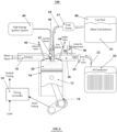
- Fig. 1 shows an engine 100 constructed in accordance with this invention.
- the engine includes a cylinder 10, with a reciprocating piston 12 driving a shaft (not shown) through a linkage 14.
- a reciprocating piston 12 driving a shaft (not shown) through a linkage 14.
- an experimental engine 100 was constructed by the inventors, by modifying a generic, off the shelf 400 cc Diesel engine.
- the engine 100 further includes a conventional air intake manifold 26 with an air intake 28 and a butterfly-type adjustment valve 30, an intake valve 64, an exhaust valve 66, an exhaust manifold 70 and a fuel injector 48.
- the modified engine 100 further includes a hydrogen source 20.
- source 20 is implemented as a reactor that generates a stoichiometric H 2 /O 2 gas mixture (herein referred to as brown gas) from water using electrolysis process.
- brown gas a stoichiometric H 2 /O 2 gas mixture
- An example of such process is described in more detail in U.S. Patent Application Publications 2010/0122902 and 2011/0203977 .
- the brown gas is fed through a tube 22 and a valve 24 into intake manifold 26. It should be understood that the amount of brown gas introduced into the intake manifold as compared to the amount of air (that inherently also includes oxygen) is so small that the oxygen from the brown gas is negligible and can be ignored.
- the brown gas generator is used as a source of hydrogen.
- other types of hydrogen generator can be used as alternatives to the brown gas generator as well.
- the intake manifold 26 also receives ambient air through the air intake 28 and, as will be discussed in more detail below, the amount of air flowing into the chamber 26 is controlled by the valve 30.
- the engine 100 further includes a fuel tank 40 holding a fuel 42.
- the fuel 42 is provided through a tube 44 by pump 46 to the fuel injector 48.
- the fuel in the fuel tank consists essentially of water and a flammable substance soluble in water. More specifically, it is believed that the flammable substance should be 30% soluble in water by volume.
- the flammable substance may include, alcohol, acetone, aldehyde and other similar, preferably non-fossil substances or mixtures thereof.
- the flammable substance is an alcohol selected from iso-propyl alcohol, iso butanol, propyl alcohol, butyl alcohol, ethyl alcohol, methyl alcohol or a mixture of such alcohols.
- the flammable substance is one of formaldehyde, acetaldehyde, butyraldehyde, benzaledehyde, cinnamaldehyde, tolualdehyde,furfural, retinaldehyde, glyoxal, malondaldehyde, succindialdehyde, glutaraldehyde, phtalaaldehyde or mixtures thereof.
- the concentration of the flammable material can be in the range of 5-40%, and preferably 10-35%.
- the inventors have found that, in particular a mixture of about 70% water to 30% isopropyl alcohol is particularly advantageous in that it provides a favorable cost vs. performance characteristics.
- the fuel 42 from the fuel tank 40 is provided to the fuel injector 48 by pump 43 at a pressure in the range of 14-207 bar. In one embodiment, the fuel is injected at a pressure of about 138 bar.
- Systems have been proposed in the past in which water has been separated via electrolysis into H 2 /O 2 mixture and then was fed in to the engine intake system.
- the main fuel used in such known engines was a fossil fuel.
- the fuel 42 is essentially an aqueous mixture of a flammable material, preferably with no fossil components.
- the engine 100 also includes a high-energy ignition system 60 providing electrical current to an ignition device 62 (such as a standard spark plug) extending into the chamber 50 as shown.
- the system 60 and spark plug 62 are conventional components used for internal combustion engines using gasoline as fuel.
- a timing controller 54 receives input timing signals and a load signal indicative of the load on the engine 100.
- the input timing signals are typically derived from the position of the crankshaft (not shown).
- the load signal is indicative of the load on the engine 100 are derived using conventional techniques.
- the timing controller generates output timing signals that control the operation of ignition device 62, fuel injector 48, valve 24 and air intake valve 30, valves 64 and 66 open and close it controlled by a traditional camshaft (not shown).
- the engine 100 operates at a very high compression ratio.
- a conventional combustion engine operates at a compression ratio of around 15/1 to 18/1, except for some very special engines, such as the engines used car racing.
- the present invention can be constructed to operate in the range of 10/1-40/1, and preferably in the range of 25/1-35/1.
- An optimal compression ratio is about 30/1.
- This high compression ratio can be achieved by shaping the head of the top of the piston to reduce the volume of the combustion chamber.
- the top surface of the piston 12 can be shaped with an indentation 70. This indentation has a predetermined size and shape selected to provide the required compression ratio and to generate turbulence in fuel plume 52.
- the indentation 70 is placed so that as the piston 12 is moves upward toward the top of the cylinder and the plume of fuel 52 is released by the fuel injector 48, the plume 52 using the shape of the surface of the indentation causing it to swirl.
- a single plume 52 is released by the fuel injector 48 in every intake cycle.
- 1-5 plumes are released, depending on several variables, such as the type of fuel being used, the load on the engine, ambient temperature, etc. If more than the one plume is released, the first plume is released much earlier than the combustion point, to enrich the vapor mixture in the chamber 50, and the other plumes are released just prior to combustion, as well during combustion.
- the engine 100 operates in a manner similar to a standard four-cycle internal combustion engine but with some important differences.
- the valves 30, 24 and 64 open to allow air and brown gas to enter into and mix in chamber 50.
- the ratio of brown gas to the volume of the cylinder is very small by volume (about 1 ⁇ 2-2%), that the amount of O 2 in the brown gas as compared to the amount of O 2 in the air is negligible and, and therefore only the hydrogen (H 2 ) is of any real importance.
- valve 64 closes, and the piston 12 moves upward compressing the gases in chamber 50.
- a plume 52 of fine droplets of fuel is injected into the chamber 50 by fuel injector 48 and it mixes with the air/H 2 mixture.
- the piston 12 keeps moving upward compressing further to a very high pressure and temperature which create a very explosive content inside the combustion chamber 50.
- the mixture in chamber 50 is ignited (typically at top dead center) by spark plug 62 or other ignition device causing combustion that converts the mixture within the chamber 50 into very hot and highly pressurized gases including steam. These gases force the piston 12 to move down in the conventional manner.
- the next upward movement (exhaust cycle) of the piston 12 causes the remains of the combustion to be exhausted through manifold 70. These remains consist mostly of water vapor.
- engine 100 can run at 2500 RPM indefinitely, even when the air intake adjustment valve 30 is closed, and therefore almost no air (and, very little oxygen) is provided to the engine.
- air intake adjustment valve 30 is closed, and therefore almost no air (and, very little oxygen) is provided to the engine.
- at substantially no load it was found that engine 100 can run at 2500 RPM indefinitely, even when the air intake adjustment valve 30 is closed, and therefore almost no air (and, very little oxygen) is provided to the engine.
- the water from the fuel disassociates into H 2 and O 2 and provides the oxygen necessary for the combustion. The remainder of the water is apparently turning into steam.
- valve 30 should be opened; otherwise the engine is slowing down and can stops running.
- the amount of air being introduced through valve 30 is dependent on the load on the engine and, since apparently the air is not needed for the combustion, it is believed that, as the load increases, in order to maintain RPM and produce power against the load, a higher torque is needed, the air is needed as a working gas that create a higher combustion pressure which intern create a higher torque when is pushing the piston down
- the operating parameters of the engine 100 as described are as follows:
- the first injection or pilot consists of 5-30 % of the total fuel and the remainder is then rationed during the combustion cycle.
- the fuel is preferably a solution of water and a flammable liquid substance.
- an additive can be added, such as a non corrosive material that increase the conductivity of the water at high pressure during combustion thereby helping the separation of the water to H 2 /O 2 .
- the techniques shown can be easily applied multiple cylinder, in addition to a regular piston or a rotary engine, the invention can be developed turbine and jet engine as well.
- a conversion of a Diesel based engine is fairly simple, only the head is needed to be modified in order to introduce the ignition device, a high power ignition system, the shape of the piston and the combustion chamber to allow a suitable compression ratio, and a fairly small H 2 /O 2 reactor (or other H 2 source) need to be added, making this solution an inexpensive and simple to introduce to the market place.
- the flammable substance can be automatically mixed with clean water and fed in to the fuel tank of the vehicle.
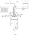
- Fig. 3 shows another embodiment.
- engine 200 is very similar to engine 100.
- the difference is that a novel mixing chamber 210 is provided at the top of the cylinder 10 in communication with the cylinder portion 50 where the combustion takes place.
- the H 2 /O 2 mixture is fed by a second injector 220 into this mixing chamber 210 (rather than into the chamber 50).
- the mixing chamber 210 receives both the fuel mixture 42 and the H 2 /O 2 mixture. These materials mix with each other and are sucked into the portion 50 when required through a channel 230.
- Fig. 4 shows another embodiment 300.
- the water fuel mixture and the H 2 /O 2 mixture are both fed directly into the combustion chamber.
- the H 2 /O 2 mixture can be fed to the engine in three different ways: into the manifold, into a mixing chamber, or into the combustion chamber itself.
- the present invention has several advantages. First, it makes use of commonly available renewable substances as fuel, instead of relying on non-renewable fossil substances. It is believed that the invention is much more efficient and similar engines using on fossil-based fuels and can generate more power. Third, during the experiments performed on the engine, the exhaust from the engine was very clean, minimal pollution being observed, and even in a non ventilated area there was no visible smoke, nor did the inventor found any difficulty breathing.
Description
- This invention pertains to a method and apparatus for operating an internal combustion engine using a fuel consisting of water and a water-soluble flammable substance that is injected into a mixture of hydrogen and air.
- The use of fossil fuels to run engines that used, for example, in cars and other vehicles, as well as many other engines used for a variety of purposes, is based on a very old concept based on the internal combustion engines developed in the nineteenth century. Despite intense research and development for alternate fuels for the last 50 years, fossil fuel derived from petroleum or natural gas, is still essentially the primary source of energy almost all the internal combustion engines presently in use all over the world.
- As a result, the world supply of fossil fuels have been severely depleted creating a shortage, and the price of oil has been climbing for the past 40 years. In addition such fuels are very polluting and some suggest that it has either been the primary cause or has contributed substantially to global warming. All these factors led to many efforts to find and harness renewable energy sources other than traditional fossil fuels. Several alternative fuels have been introduced in the past few years to reduce the impact of petroleum depletion, including hybrid cars, electric cars, bio diesel, hydrogen based cars, etc. However, none of these solutions were effective. One reason for this lack of success is that they require a completely new infrastructure for the production of the engines, as well as the production and distribution of the fuel. Moreover, the most solutions proposed so far were incompatible with the existing engines and, therefore. The cost of replacing all the existing fossil burning engines may be so high that it may render any solution based on alternate fuels unacceptable, at least, in a short term basis.
- Water as a source of fuel has been suggested by many in the past and many experiments have been conducted testing such systems. The basis of such experiments is the fact that water can be separated in to hydrogen and oxygen and the resulting stoichiometric mixture can be fed in to an internal combustion engine to generate power. However past experiments yielded unsatisfactory results. The main obstacle for their success is based on the fact that the energy required to separate the water into its components is much greater than the energy produce by the engine. In addition the amount H2 mixture needed to run a typical automotive engine is too large to make such a system practical.
- Systems are presently available on market that can be used as accessories or add-ons to internal combustion engines using fossil fuels, however independent tests have shown that, in fact, these systems have very little, if any, effect on the overall efficiency of the engine.
- A system developed by the present inventors is described in two co-pending applications includes means of generating from water and supplying a small amount of hydrogen/oxygen gas mixture into a standard internal combustion engine. (See
U.S. Patent Application Publications 2010/0122902 ,2011/0203977 andWO2008/077204 ). More specifically, these co-pending applications describe an efficient process and apparatus for generating a two-to-one mixture of hydrogen and oxygen, commonly referred to as brown gas or HHO. The mixture helps increase the efficiency of the conventional internal combustion engine by burning the fossil fuel more efficiently. While this latter system is much more efficient than previously described systems; its efficiency is still limited by the amount of hydrogen and oxygen produced on board a vehicle. Moreover, the internal combustion engine described is still burning a fossil fuel. - Briefly, an internal combustion engine includes a cylinder with a combustion chamber having a variable volume as defined by a reciprocating piston in a generally conventional manner. Hydrogen and air are initially fed into the combustion chamber. Then, a fuel in form of fine droplets of liquid are injected into the compressed combustion chamber. The resulting liquid/gas mixture is then compressed to a very high pressure, which causes the temperature to rise, and an ignition device causes combustion. The combustion results in hot and pressurized gases that cause the piston to move and generate power. Advantageously, the fuel consists essentially of water and a flammable substance. The flammable material is an alcohol, acetone, aldehyde or other flammable, preferably non-fossil substance that is soluble in water. (The term non-fossil is used to refer to a fuel that is not derived substantially from fossil-base, non renewable materials, such oil or natural gas, but from a renewable source.) Preferably the fuel contains approximately 10-40% flammable material by volume.
- The system and method described herein can be adapted to any engine such as rotary and jet engines and are not limited to a piston based as long as the engine can be used to implement the basic principle of the invention,. This basic principle includes (1) mixing hydrogen and air with a solution of water and a flammable, water soluble fuel (2) compressing the mixture to a high pressure to create high heat and a very explosive mixture in a combustion chamber, and (3)igniting the explosive mixture to cause the sudden expansion of such gases and the formation of steam thereby generating mechanical power.
-
-
Fig. 1 shows a first embodiment of the invention in which H2, air and an aqueous solution forming a fuel is introduced directly into the combustion chamber of the engine with the H2 and the air being introduced through a common intake; -
Figs. 2A and 2B show sectional and side views of some elements of an internal combustion engine constructed in accordance with this invention; -
Fig. 3 shows a second embodiment in which the ingredients are first mixed in a mixing chamber before exploding. -
Fig. 4 shows a third embodiment of the invention in which air is introduced trough the intake manifold and H2 are introduced by way of injection directly to the compression chamber. -
Fig. 1 shows anengine 100 constructed in accordance with this invention. The engine includes acylinder 10, with areciprocating piston 12 driving a shaft (not shown) through alinkage 14. For example, anexperimental engine 100 was constructed by the inventors, by modifying a generic, off the shelf 400 cc Diesel engine. Theengine 100 further includes a conventionalair intake manifold 26 with anair intake 28 and a butterfly-type adjustment valve 30, anintake valve 64, anexhaust valve 66, anexhaust manifold 70 and afuel injector 48. - In a conventional four cycle Diesel engine, air is sucked in through
manifold 26 into thecombustion chamber 50 of thecylinder 10 while thepiston 12 moves down. Theintake valve 64 than closes, thepiston 12 moves up and a Diesel fuel is injected by theinjector 48 into thechamber 50. Thepiston 12 compresses the mixture of air and fuel and combustion occurs. Thepiston 12 then moves down to drive the shaft and moves up again, and theexhaust valve 66 opens exhausting the remaining gases through theexhaust manifold 70. - The modified
engine 100 further includes ahydrogen source 20. In one embodiment,source 20 is implemented as a reactor that generates a stoichiometric H2/O2 gas mixture (herein referred to as brown gas) from water using electrolysis process. An example of such process is described in more detail inU.S. Patent Application Publications 2010/0122902 and2011/0203977 . The brown gas is fed through atube 22 and avalve 24 intointake manifold 26. It should be understood that the amount of brown gas introduced into the intake manifold as compared to the amount of air (that inherently also includes oxygen) is so small that the oxygen from the brown gas is negligible and can be ignored. In effect, the brown gas generator is used as a source of hydrogen. Obviously, other types of hydrogen generator can be used as alternatives to the brown gas generator as well. - The
intake manifold 26 also receives ambient air through theair intake 28 and, as will be discussed in more detail below, the amount of air flowing into thechamber 26 is controlled by thevalve 30. - The
engine 100 further includes afuel tank 40 holding afuel 42. Thefuel 42 is provided through atube 44 by pump 46 to thefuel injector 48. - The fuel in the fuel tank consists essentially of water and a flammable substance soluble in water. More specifically, it is believed that the flammable substance should be 30% soluble in water by volume. The flammable substance may include, alcohol, acetone, aldehyde and other similar, preferably non-fossil substances or mixtures thereof. In a preferred embodiment, the flammable substance is an alcohol selected from iso-propyl alcohol, iso butanol, propyl alcohol, butyl alcohol, ethyl alcohol, methyl alcohol or a mixture of such alcohols.
- Alternatively, the flammable substance is one of formaldehyde, acetaldehyde, butyraldehyde, benzaledehyde, cinnamaldehyde, tolualdehyde,furfural, retinaldehyde, glyoxal, malondaldehyde, succindialdehyde, glutaraldehyde, phtalaaldehyde or mixtures thereof.
- The concentration of the flammable material can be in the range of 5-40%, and preferably 10-35%. The inventors have found that, in particular a mixture of about 70% water to 30% isopropyl alcohol is particularly advantageous in that it provides a favorable cost vs. performance characteristics.
- The
fuel 42 from thefuel tank 40 is provided to thefuel injector 48 bypump 43 at a pressure in the range of 14-207 bar. In one embodiment, the fuel is injected at a pressure of about 138 bar. Systems have been proposed in the past in which water has been separated via electrolysis into H2/O2 mixture and then was fed in to the engine intake system. The main fuel used in such known engines was a fossil fuel. In thepresent engine 100, thefuel 42 is essentially an aqueous mixture of a flammable material, preferably with no fossil components. - The
engine 100 also includes a high-energy ignition system 60 providing electrical current to an ignition device 62 (such as a standard spark plug) extending into thechamber 50 as shown. Thesystem 60 andspark plug 62 are conventional components used for internal combustion engines using gasoline as fuel. - A timing controller 54 (typically including a microprocessor-not shown) receives input timing signals and a load signal indicative of the load on the
engine 100. The input timing signals are typically derived from the position of the crankshaft (not shown). The load signal is indicative of the load on theengine 100 are derived using conventional techniques. In response, the timing controller generates output timing signals that control the operation ofignition device 62,fuel injector 48,valve 24 andair intake valve 30,valves - Importantly, the
engine 100 operates at a very high compression ratio. Typically, a conventional combustion engine operates at a compression ratio of around 15/1 to 18/1, except for some very special engines, such as the engines used car racing. The present invention can be constructed to operate in the range of 10/1-40/1, and preferably in the range of 25/1-35/1. An optimal compression ratio is about 30/1. This high compression ratio can be achieved by shaping the head of the top of the piston to reduce the volume of the combustion chamber. For example, as shown inFigs. 2A and 2B , the top surface of thepiston 12 can be shaped with anindentation 70. This indentation has a predetermined size and shape selected to provide the required compression ratio and to generate turbulence infuel plume 52. For this purpose, theindentation 70 is placed so that as thepiston 12 is moves upward toward the top of the cylinder and the plume offuel 52 is released by thefuel injector 48, theplume 52 using the shape of the surface of the indentation causing it to swirl. - In one embodiment of the invention, a
single plume 52 is released by thefuel injector 48 in every intake cycle. In an alternate embodiment, 1-5 plumes are released, depending on several variables, such as the type of fuel being used, the load on the engine, ambient temperature, etc. If more than the one plume is released, the first plume is released much earlier than the combustion point, to enrich the vapor mixture in thechamber 50, and the other plumes are released just prior to combustion, as well during combustion. - The
engine 100 operates in a manner similar to a standard four-cycle internal combustion engine but with some important differences. During the intake cycle, as thepiston 12 moves downward, thevalves chamber 50. As explained above, the ratio of brown gas to the volume of the cylinder is very small by volume (about ½-2%), that the amount of O2 in the brown gas as compared to the amount of O2 in the air is negligible and, and therefore only the hydrogen (H2) is of any real importance. Next, during the compression cycle,valve 64 closes, and thepiston 12 moves upward compressing the gases inchamber 50. At a predetermined point, e.g., typically at around 20 degrees btdc (before top dead center), aplume 52 of fine droplets of fuel is injected into thechamber 50 byfuel injector 48 and it mixes with the air/H2 mixture. Thepiston 12 keeps moving upward compressing further to a very high pressure and temperature which create a very explosive content inside thecombustion chamber 50. The mixture inchamber 50 is ignited (typically at top dead center) byspark plug 62 or other ignition device causing combustion that converts the mixture within thechamber 50 into very hot and highly pressurized gases including steam. These gases force thepiston 12 to move down in the conventional manner. The next upward movement (exhaust cycle) of thepiston 12 causes the remains of the combustion to be exhausted throughmanifold 70. These remains consist mostly of water vapor. - Surprisingly, at substantially no load, it was found that
engine 100 can run at 2500 RPM indefinitely, even when the airintake adjustment valve 30 is closed, and therefore almost no air (and, very little oxygen) is provided to the engine. Apparently, during the compression and/or explosion stages least some of the water from the fuel disassociates into H2 and O2 and provides the oxygen necessary for the combustion. The remainder of the water is apparently turning into steam. - As the load on the engine increases, the
valve 30 should be opened; otherwise the engine is slowing down and can stops running. The amount of air being introduced throughvalve 30 is dependent on the load on the engine and, since apparently the air is not needed for the combustion, it is believed that, as the load increases, in order to maintain RPM and produce power against the load, a higher torque is needed, the air is needed as a working gas that create a higher combustion pressure which intern create a higher torque when is pushing the piston down - The operating parameters of the
engine 100 as described are as follows: -
Compression ratio 30/1; -
Fuel 70% water 30% iso-propyl alcohol at ambient temperature; - H2 2-10 l/min at standard atmospheric pressure and ambient temperature;
- Air 0-50 l/min at ambient pressure and temperature.
- Fuel pressure 14-207 bar
- If multiple injections are used, the first injection or pilot consists of 5-30 % of the total fuel and the remainder is then rationed during the combustion cycle.
- While presently the exact phenomenon occurring in the
cylinder portion 50 during explosion is not fully understood, it is believed that some if not all of the water from the fuel mixture also disassociates in the cylinder into H2 and O2 and provides more fuel for conversion which is triggered by the H2/O2 that is fed in to the chamber, It was found that the process worked well when a volume of 2 ml. of the H2/O2 gas mixture was provided to the engine for every revolution. Since the engine is a 400 ml (or 400 cc) engine,. The amount of H2/O2 provided for each revolution is about ½-2% of H2 by volume - As discussed above, the fuel is preferably a solution of water and a flammable liquid substance. In addition an additive can be added, such as a non corrosive material that increase the conductivity of the water at high pressure during combustion thereby helping the separation of the water to H2/O2.
- The techniques shown can be easily applied multiple cylinder, in addition to a regular piston or a rotary engine, the invention can be developed turbine and jet engine as well.
- For example a conversion of a Diesel based engine is fairly simple, only the head is needed to be modified in order to introduce the ignition device, a high power ignition system, the shape of the piston and the combustion chamber to allow a suitable compression ratio, and a fairly small H2/O2 reactor (or other H2 source) need to be added, making this solution an inexpensive and simple to introduce to the market place.
- Since water is practically available in any fuel station, no main infrastructure needed to be created. The flammable substance can be automatically mixed with clean water and fed in to the fuel tank of the vehicle.
-
Fig. 3 shows another embodiment. In this embodiment,engine 200 is very similar toengine 100. The difference is that anovel mixing chamber 210 is provided at the top of thecylinder 10 in communication with thecylinder portion 50 where the combustion takes place. The H2/O2 mixture is fed by asecond injector 220 into this mixing chamber 210 (rather than into the chamber 50). Thus, the mixingchamber 210 receives both thefuel mixture 42 and the H2/O2 mixture. These materials mix with each other and are sucked into theportion 50 when required through achannel 230. -
Fig. 4 shows anotherembodiment 300. In this embodiment, the water fuel mixture and the H2/O2 mixture are both fed directly into the combustion chamber. - In other words, the H2/O2 mixture can be fed to the engine in three different ways: into the manifold, into a mixing chamber, or into the combustion chamber itself.
- The present invention has several advantages. First, it makes use of commonly available renewable substances as fuel, instead of relying on non-renewable fossil substances. It is believed that the invention is much more efficient and similar engines using on fossil-based fuels and can generate more power. Third, during the experiments performed on the engine, the exhaust from the engine was very clean, minimal pollution being observed, and even in a non ventilated area there was no visible smoke, nor did the inventor found any difficulty breathing.
Claims (16)
- An internal combustion engine (100; 200; 300) for use with only non-fossil fuel, the engine comprising:at least one cylinder (10) having a combustion chamber (50);an intake manifold (26) in selective fluid communication with the combustion chamber;a hydrogen source (20) configured to provide hydrogen, and an oxygen source configured to provide oxygen, at least one of the hydrogen source and the oxygen source in fluid communication with the intake manifold to provide at least one of hydrogen and oxygen to the combustion cylinder through the intake manifold;a fuel source (42) configured to provide a fuel;a fuel injector (48) configured to selectively inject the fuel from the fuel source to the combustion chamber;at least one piston (12) in the at least one cylinder and structured to move within the at least one cylinder and compress the hydrogen, oxygen, and fuel together in the combustion chamber with a compression ratio in the range of 10: 1 to 40:1; andan ignition device (62) configured to ignite the compressed hydrogen, oxygen, and fuel in the combustion chamber to generate power;characterized in that the fuel source is configured to provide only a non-fossil fuel consisting essentially of 70% water and 30% alcohol.
- The engine (100; 200; 300) of claim 1 wherein the fuel is injected into the combustion chamber (50) at a pressure in the range of 14-207 bar.
- The engine (100; 200; 300) of claim 1 wherein the fuel or the hydrogen is injected into the combustion chamber (50) at ambient temperature.
- The engine (200) of claim 1 wherein the hydrogen source is configured to be in selective fluid communication with the combustion chamber (50) via an injector (220) and the oxygen source is configured to be in selective fluid communication with the combustion chamber via the intake manifold.
- The engine (100; 200; 300) of claim 1 wherein the alcohol is isopropyl alcohol.
- The engine (100; 200; 300) of claim 1 wherein the compressed hydrogen, oxygen, and fuel includes about ½% to 10% hydrogen by volume
- A method of generating power using a non-fossil fueled internal combustion engine (100), the method comprising:introducing hydrogen and oxygen into a combustion chamber (50) of the internal combustion engine, the introducing including introducing at least one of the hydrogen and the oxygen into the combustion chamber via an intake manifold (26);introducing a fuel into the combustion chamber using a fuel injector (48);compressing the hydrogen, oxygen, and the fuel with a piston (12) in the combustion chamber with a compression ratio in the range of 10: 1 to 40: 1; andigniting the compressed hydrogen, oxygen, and fuel in the combustion chamber to create hot compressed gases and generate power;characterized in that the introduced fuel is a non-fossil fuel consisting essentially of 70% water and 30% alcohol.
- The method of claim 7 wherein the introducing a non-fossil fuel comprises injecting the fuel into the combustion chamber (50) at a pressure in the range of 14-207 bar.
- The method of claim 7 comprising mixing the hydrogen, oxygen, and fuel in a mixing chamber (210) prior to the introducing.
- The method of claim 7 wherein the introducing the non-fossil fuel comprises injecting the fuel into the combustion chamber (50) at ambient temperature.
- The method of claim 7 wherein the introducing the hydrogen comprises injecting the hydrogen into the combustion chamber (50) at ambient temperature.
- The method of claim 7 wherein the compressed hydrogen, oxygen, and fuel includes about ½% to 10% hydrogen by volume.
- The method of claim 7 wherein the alcohol comprises isopropyl alcohol, and wherein the introducing the non-fossil fuel comprises injecting the fuel into the combustion chamber (50) at ambient temperature, and further wherein the introducing the hydrogen comprises injecting the hydrogen into the combustion chamber at ambient temperature.
- The method of claim 13 wherein the compressed hydrogen, oxygen, and fuel includes about ½% to 10% hydrogen by volume.
- The method of claim 14 further comprising mixing the hydrogen, oxygen, and fuel in a mixing chamber prior to the injection of the hydrogen and the fuel into the combustion chamber (50) at ambient temperature.
- A vehicle, comprising an internal combustion engine (100; 200; 300) according to any of claims 1 to 6.
Applications Claiming Priority (2)
| Application Number | Priority Date | Filing Date | Title |
|---|---|---|---|
| US201261613550P | 2012-03-21 | 2012-03-21 | |
| PCT/US2013/033100 WO2013142575A1 (en) | 2012-03-21 | 2013-03-20 | Internal combustion engine using a water-based mixture as fuel and method for operating the same |
Publications (4)
| Publication Number | Publication Date |
|---|---|
| EP2828509A1 EP2828509A1 (en) | 2015-01-28 |
| EP2828509A4 EP2828509A4 (en) | 2016-04-13 |
| EP2828509B1 true EP2828509B1 (en) | 2023-08-02 |
| EP2828509C0 EP2828509C0 (en) | 2023-08-02 |
Family
ID=49210600
Family Applications (1)
| Application Number | Title | Priority Date | Filing Date |
|---|---|---|---|
| EP13764997.6A Active EP2828509B1 (en) | 2012-03-21 | 2013-03-20 | Internal combustion engine using a water-based mixture as fuel and method for operating the same |
Country Status (13)
| Country | Link |
|---|---|
| US (1) | US9074555B2 (en) |
| EP (1) | EP2828509B1 (en) |
| JP (3) | JP2015512481A (en) |
| KR (2) | KR102227241B1 (en) |
| CN (2) | CN104334858B (en) |
| AU (2) | AU2013235173B2 (en) |
| CA (1) | CA2868166C (en) |
| IL (1) | IL234731A (en) |
| IN (1) | IN2014DN08453A (en) |
| MX (1) | MX364927B (en) |
| RU (2) | RU2674168C2 (en) |
| WO (1) | WO2013142575A1 (en) |
| ZA (1) | ZA201407612B (en) |
Families Citing this family (18)
| Publication number | Priority date | Publication date | Assignee | Title |
|---|---|---|---|---|
| MX355007B (en) | 2012-02-27 | 2018-03-28 | Deec Inc | Oxygen-rich plasma generators for boosting internal combustion engines. |
| CN104334858B (en) * | 2012-03-21 | 2018-10-09 | 玫玛研究有限责任公司 | Using the mixture based on water as the internal combustion engine of fuel and the method for operating it |
| WO2015048187A1 (en) * | 2013-09-25 | 2015-04-02 | Yehuda Shmueli | Internal combustion engine using a water-based mixture as fuel and method for operating the same |
| US20150285135A1 (en) * | 2014-04-04 | 2015-10-08 | Nexovation, Inc. | Combustion engine including an air injector, and power generating system including the combustion engine |
| US10634070B2 (en) * | 2014-04-23 | 2020-04-28 | American United Energy, Inc. | Fuel control systems for operating gasoline engines based on ethanol-water-hydrogen mixture fuels |
| FR3035169B1 (en) * | 2015-04-16 | 2017-05-05 | Technip France | DEVICE FOR MONITORING THE FILLING OF A PIPE DURING INSTALLATION IN A WATER EXTENDER, ASSOCIATED ASSEMBLY AND METHOD |
| US9828948B2 (en) * | 2015-12-02 | 2017-11-28 | Ford Global Technologies, Llc | Method and system for determining knock control fluid composition |
| KR20220123330A (en) | 2016-03-07 | 2022-09-06 | 하이테크 파워, 인크. | A method of generating and distributing a second fuel for an internal combustion engine |
| JP6679435B2 (en) * | 2016-07-14 | 2020-04-15 | ヤンマー株式会社 | engine |
| NO343554B1 (en) * | 2017-08-14 | 2019-04-01 | Lars Harald Heggen | Zero discharge propulsion system and ammonia fuel generating system |
| US20190234348A1 (en) * | 2018-01-29 | 2019-08-01 | Hytech Power, Llc | Ultra Low HHO Injection |
| GB2567704A (en) * | 2018-03-22 | 2019-04-24 | Binns Frederick | Method for fuelling diesel engines |
| WO2021011528A1 (en) | 2019-07-15 | 2021-01-21 | The Research Foundation For The State University Of New York | Method for control of advanced combustion through split direct injection of high heat of vaporization fuel or water fuel mixtures |
| CN110685827A (en) * | 2019-10-09 | 2020-01-14 | 合肥工业大学 | Structure is adjusted to engine inlet physical and chemical characteristics |
| GB2592880B (en) * | 2019-11-22 | 2022-12-07 | Caterpillar Motoren Gmbh & Co | Method and gas fuel injection unit for operating an internal combustion engine |
| CN111365119B (en) * | 2020-03-14 | 2021-07-30 | 北京工业大学 | Zero-emission two-stroke ignition type hydrogen-oxygen engine and control method |
| US11608771B2 (en) | 2020-03-16 | 2023-03-21 | Mayamaan Research, Llc | Homogeneous charge compression ignition (HCCI-type) combustion system for an engine and powertrain using wet-alcohol as a fuel and including hot assist ignition |
| WO2023004017A1 (en) * | 2021-07-22 | 2023-01-26 | Achates Power, Inc. | Hydrogen-powered opposed-piston engine |
Family Cites Families (85)
| Publication number | Priority date | Publication date | Assignee | Title |
|---|---|---|---|---|
| US2789802A (en) | 1953-09-11 | 1957-04-23 | Heftler Maurice Ben | Coasting economizers |
| US3738576A (en) * | 1971-04-21 | 1973-06-12 | Physics Int Co | Injection nozzle for direct injection engine |
| GB1497542A (en) | 1974-05-30 | 1978-01-12 | Parel Sa | Electrochemical apparatus |
| US4170200A (en) | 1974-06-14 | 1979-10-09 | Nippondenso Co., Ltd. | Internal combustion engine with reformed gas generator |
| US4111160A (en) | 1976-04-16 | 1978-09-05 | Talenti Pier F | Method and apparatus for operating combustion engines |
| BE873331A (en) * | 1978-01-16 | 1979-07-05 | Engelhard Min & Chem | COMBUSTION CONTROL DEVICE FOR AN INTERNAL COMBUSTION ENGINE USING FUELS WITH A VARIABLE PROPORTION OF PARTLY OXIDIZED HYDROCARBONS |
| BR8000889A (en) * | 1979-02-21 | 1980-10-21 | Basf Ag | CARBURETTING COMPOSITES FOR DIESEL ENGINES |
| US4249654A (en) | 1979-09-25 | 1981-02-10 | Helversen Frederick D | Hydrogen storage apparatus |
| EP0045601A1 (en) * | 1980-07-31 | 1982-02-10 | Pate-Hansen Enterprises, Inc. | Vapour fuel system for an internal combustion engine |
| US4442801A (en) | 1981-12-16 | 1984-04-17 | Glynn John D | Electrolysis fuel supplementation apparatus for combustion engines |
| US4509464A (en) | 1982-07-26 | 1985-04-09 | Hansen Herbert N W | High efficiency internal combustion steam engine |
| US4484444A (en) | 1982-07-29 | 1984-11-27 | Howard Bidwell | Apparatus and methods of amplifying engine emissions by which to increase the overall engine efficiency |
| JPS60125762A (en) * | 1983-12-13 | 1985-07-05 | Nippon Mining Co Ltd | Operation of diesel engine by low-grade alcohol |
| US4599088A (en) * | 1984-08-30 | 1986-07-08 | Texaco Inc. | Clear stable gasoline-alcohol-water motor fuel composition |
| US6155212A (en) * | 1989-06-12 | 2000-12-05 | Mcalister; Roy E. | Method and apparatus for operation of combustion engines |
| JPH03124929A (en) * | 1989-10-06 | 1991-05-28 | Toyota Motor Corp | Fuel injection control device of alcohol-mixed fuel vehicle |
| KR0140975B1 (en) * | 1989-11-22 | 1998-07-01 | 더블유. 군너만 루돌프 | Aqueous fuel for internal combustion engine and method of combustion |
| US5156114A (en) * | 1989-11-22 | 1992-10-20 | Gunnerman Rudolf W | Aqueous fuel for internal combustion engine and method of combustion |
| US5007381A (en) * | 1990-01-22 | 1991-04-16 | Advance Combustion Engineering Institute Co., Ltd. | Method to decrease black smoke of diesel |
| JP2502182B2 (en) * | 1990-10-01 | 1996-05-29 | 三菱電機株式会社 | Elevator hall device |
| WO1992007922A1 (en) * | 1990-11-05 | 1992-05-14 | Gunnerman Rudolf W | Aqueous fuel and combustion method for engines |
| PT97742B (en) * | 1990-11-05 | 1999-03-31 | Gunnerman Rudolf W | PROCESS FOR COMBUSTION OF AN AQUEOUS COMBUSTIBLE IN AN INTERNAL COMBUSTION ENGINE |
| JPH06280696A (en) | 1993-03-25 | 1994-10-04 | Toyota Motor Corp | Fuel evaporated gas restraining device of internal combustion engine |
| US5546908A (en) | 1994-01-07 | 1996-08-20 | Stokes; Richard A. | Plural fuel system for internal combustion engine |
| US6302929B1 (en) | 1994-04-04 | 2001-10-16 | Rudolf W. Gunnerman | Aqueous fuel for internal combustion engine and method of preparing |
| DE69521204T2 (en) * | 1994-07-13 | 2002-06-06 | Univ Melbourne Parkville | IGNITION DEVICE FOR INTERNAL COMBUSTION ENGINES |
| DE19540993C1 (en) | 1995-11-03 | 1997-07-24 | Richard Krauss | Economising consumption of fossil fuel by internal combustion engines |
| JPH10306750A (en) * | 1997-05-09 | 1998-11-17 | Nichijiyuu New Material Kk | Combustion method in gasoline engine |
| US5992397A (en) | 1997-06-30 | 1999-11-30 | Hideaki; Watase | Combustion enhancing apparatus and method |
| US6299744B1 (en) | 1997-09-10 | 2001-10-09 | California Institute Of Technology | Hydrogen generation by electrolysis of aqueous organic solutions |
| WO1999013028A1 (en) * | 1997-09-12 | 1999-03-18 | Exxon Research And Engineering Company | Water emulsions of fischer-tropsch liquids |
| US5951722A (en) * | 1997-10-29 | 1999-09-14 | Sanders; James K. | Catalyzed lower alcohols-water based fuels |
| US6010544A (en) * | 1997-12-18 | 2000-01-04 | Quantum Energy Technologies | Supercritical water fuel composition and combustion system |
| JP4543440B2 (en) | 1997-12-22 | 2010-09-15 | 株式会社エクォス・リサーチ | Water direct injection fuel cell system |
| CA2269382C (en) | 1999-04-21 | 2006-05-30 | Gabi Balan | Electrode assembly |
| JP2002038981A (en) * | 2000-07-28 | 2002-02-06 | Nissan Motor Co Ltd | Internal combustion engine |
| AUPR169500A0 (en) | 2000-11-27 | 2000-12-21 | H.A.C. Technologies Pty Ltd | Hydrogen assisted combustion |
| US6866756B2 (en) | 2002-10-22 | 2005-03-15 | Dennis Klein | Hydrogen generator for uses in a vehicle fuel system |
| US6748905B2 (en) | 2002-03-04 | 2004-06-15 | The Lubrizol Corporation | Process for reducing engine wear in the operation of an internal combustion engine |
| JP3991789B2 (en) * | 2002-07-04 | 2007-10-17 | トヨタ自動車株式会社 | An internal combustion engine that compresses and ignites the mixture. |
| JP3938736B2 (en) | 2002-09-10 | 2007-06-27 | 本田技研工業株式会社 | Fuel injection device for internal combustion engine |
| CN1165602C (en) | 2002-09-16 | 2004-09-08 | 张普华 | Method and device for changing water into fuel |
| US7014740B2 (en) | 2002-12-11 | 2006-03-21 | Sang-Nam Kim | Brown gas mass production apparatus including a line style electrolytic cell |
| US6988492B2 (en) * | 2003-06-12 | 2006-01-24 | Michael Shetley | Hydrogen and liquid fuel injection system |
| JP4140844B2 (en) | 2003-08-06 | 2008-08-27 | 廣 熊谷 | Information terminal equipment power on / off system and recording medium |
| JP2005290984A (en) * | 2003-09-17 | 2005-10-20 | Noble Paul | Fuel converter |
| ES2694251T3 (en) * | 2004-01-12 | 2018-12-19 | Liquidpiston, Inc. | Hybrid cycle combustion engine and methods |
| DE102004023409B4 (en) * | 2004-05-12 | 2007-05-16 | Gottfried Schubert | High-compression gasoline engine with throttle control, spark ignition and direct fuel injection into a pre-combustion chamber |
| WO2006017321A2 (en) * | 2004-07-13 | 2006-02-16 | Tyma, Inc. | Fuel supply system for a vehicle including a vaporization device for converting fuel and water into hydrogen |
| JP2006037064A (en) * | 2004-07-26 | 2006-02-09 | Nabeshima Masao | Fuel for diesel engine |
| DE102004045638A1 (en) | 2004-09-21 | 2006-04-06 | Bayerische Motoren Werke Ag | Heat exchanger for hydrogen-powered fuel supply systems |
| JP4887836B2 (en) * | 2006-03-01 | 2012-02-29 | 日産自動車株式会社 | Internal combustion engine |
| US7665428B2 (en) * | 2006-03-17 | 2010-02-23 | Ford Global Technologies, Llc | Apparatus with mixed fuel separator and method of separating a mixed fuel |
| US7546826B2 (en) * | 2006-03-31 | 2009-06-16 | Transonic Combustion, Inc. | Injector-ignition for an internal combustion engine |
| US8469009B2 (en) * | 2006-03-31 | 2013-06-25 | Westport Power Inc. | Method and apparatus of fuelling an internal combustion engine with hydrogen and methane |
| JP4827592B2 (en) * | 2006-04-11 | 2011-11-30 | 本田技研工業株式会社 | Control device for internal combustion engine |
| WO2007147008A2 (en) * | 2006-06-13 | 2007-12-21 | Monsanto Technology Llc | Reformed alcohol power systems |
| WO2008077204A2 (en) * | 2006-12-22 | 2008-07-03 | Dominique Bosteels | Catalytic combustion process with rejuvenation step |
| JP2008291726A (en) * | 2007-05-24 | 2008-12-04 | Suzuki Motor Corp | Six cycle engine |
| CN101092919A (en) * | 2007-07-12 | 2007-12-26 | 李钢坤 | Fuel system of engine of using mixed burning alcohol and oxygen |
| EP2206763B1 (en) | 2007-09-13 | 2018-08-01 | Kabushiki Kaisha Sangi | Process for production of composition by using alcohol as starting material |
| JP4840307B2 (en) | 2007-09-20 | 2011-12-21 | 株式会社豊田中央研究所 | Engine system |
| US8763590B2 (en) | 2007-10-05 | 2014-07-01 | Petrolfree, Inc. | Method and apparatus for enhancing the utilization of fuel in an internal combustion engine |
| US20090092887A1 (en) | 2007-10-05 | 2009-04-09 | Quantumsphere, Inc. | Nanoparticle coated electrode and method of manufacture |
| WO2009064712A1 (en) * | 2007-11-12 | 2009-05-22 | Massachusetts Inst Technology | Fuel management system tor very high efficiency flex fuel engines |
| BE1017913A5 (en) * | 2007-12-24 | 2009-11-03 | Vandenberghe Erwin Erik Paul Georges | INTERNAL COMBUSTION ENGINE. |
| JP4837694B2 (en) * | 2008-03-12 | 2011-12-14 | 本田技研工業株式会社 | Control device for internal combustion engine |
| JP5178253B2 (en) * | 2008-03-13 | 2013-04-10 | Jx日鉱日石エネルギー株式会社 | Fuel for premixed compression self-ignition engines |
| US20100122902A1 (en) | 2008-11-14 | 2010-05-20 | Yehuda Shmueli | System for the electrolytic production of hydrogen as a fuel for an internal combustion engine |
| US20110203917A1 (en) | 2008-11-14 | 2011-08-25 | Yehuda Shmueli | System for the electrolytic production of hydrogen as a fuel for an internal combustion engine |
| US20110209683A1 (en) | 2008-11-20 | 2011-09-01 | Simmons Brandon M | Method of operating a spark ignition internal combustion engine |
| JP5262645B2 (en) * | 2008-12-04 | 2013-08-14 | トヨタ自動車株式会社 | Engine fuel supply system |
| JP5056770B2 (en) * | 2009-02-10 | 2012-10-24 | トヨタ自動車株式会社 | Control device for internal combustion engine |
| JP2011052606A (en) * | 2009-09-02 | 2011-03-17 | Otics Corp | Fuel delivery pipe and method for manufacturing the same |
| GB2475068B (en) * | 2009-11-04 | 2014-06-25 | Lotus Car | A two-stroke internal combustion engine with variable compression ratio and an exhaust port shutter |
| EP2584180B1 (en) | 2010-06-16 | 2017-10-18 | Toyota Jidosha Kabushiki Kaisha | Fuel control device for an internal combustion system |
| CN102337986A (en) * | 2010-07-19 | 2012-02-01 | 陈明 | Tail gas ultra-high-pressure homogeneous deflagration zero-discharge assisting energy-saving machine main piece device |
| US8528504B2 (en) * | 2010-08-08 | 2013-09-10 | Eduardas Ceremis | Internal combustion engine enhancement device and method |
| US8887697B2 (en) * | 2010-08-11 | 2014-11-18 | Albert Chin-Tang Wey | Efficient combustion of hydrocarbon fuels in engines |
| EP2438982A1 (en) | 2010-10-06 | 2012-04-11 | Silicon Fire AG | Method for preparing and using an alcohol and use of the alcohol to improve the efficiency and performance of a combustion engine |
| EP2615279B1 (en) | 2010-11-17 | 2020-05-06 | Toyota Jidosha Kabushiki Kaisha | Control device for internal combustion engine |
| US9447724B2 (en) | 2010-11-25 | 2016-09-20 | Gane Energy & Resources Pty Ltd. | Fuel and process for powering a compression ignition engine |
| US8634939B2 (en) * | 2011-09-13 | 2014-01-21 | Ford Global Technologies, Llc | Method and system for vehicle speed control |
| CN102518533B (en) | 2011-12-12 | 2013-12-11 | 樊品良 | Alcohol and hydrogen-rich gas engine |
| CN104334858B (en) * | 2012-03-21 | 2018-10-09 | 玫玛研究有限责任公司 | Using the mixture based on water as the internal combustion engine of fuel and the method for operating it |
-
2013
- 2013-03-20 CN CN201380023382.3A patent/CN104334858B/en active Active
- 2013-03-20 WO PCT/US2013/033100 patent/WO2013142575A1/en active Application Filing
- 2013-03-20 KR KR1020197028244A patent/KR102227241B1/en active IP Right Grant
- 2013-03-20 EP EP13764997.6A patent/EP2828509B1/en active Active
- 2013-03-20 JP JP2015501878A patent/JP2015512481A/en active Pending
- 2013-03-20 KR KR1020147029447A patent/KR20140138319A/en not_active Application Discontinuation
- 2013-03-20 CN CN201811036648.9A patent/CN109469564B/en active Active
- 2013-03-20 RU RU2017117915A patent/RU2674168C2/en active
- 2013-03-20 AU AU2013235173A patent/AU2013235173B2/en active Active
- 2013-03-20 IN IN8453DEN2014 patent/IN2014DN08453A/en unknown
- 2013-03-20 RU RU2014142265A patent/RU2014142265A/en not_active Application Discontinuation
- 2013-03-20 MX MX2014011386A patent/MX364927B/en active IP Right Grant
- 2013-03-20 CA CA2868166A patent/CA2868166C/en active Active
- 2013-03-20 US US13/847,555 patent/US9074555B2/en active Active
-
2014
- 2014-09-18 IL IL234731A patent/IL234731A/en active IP Right Grant
- 2014-10-20 ZA ZA2014/07612A patent/ZA201407612B/en unknown
-
2017
- 2017-06-14 AU AU2017203995A patent/AU2017203995A1/en not_active Abandoned
- 2017-08-10 JP JP2017155663A patent/JP2017214934A/en active Pending
-
2019
- 2019-10-04 JP JP2019183919A patent/JP2020073794A/en active Pending
Also Published As
| Publication number | Publication date |
|---|---|
| CA2868166C (en) | 2021-09-21 |
| CN104334858B (en) | 2018-10-09 |
| RU2674168C2 (en) | 2018-12-05 |
| JP2015512481A (en) | 2015-04-27 |
| AU2013235173B2 (en) | 2017-03-16 |
| AU2017203995A1 (en) | 2017-07-06 |
| IL234731A (en) | 2017-11-30 |
| EP2828509A4 (en) | 2016-04-13 |
| CN109469564B (en) | 2021-12-07 |
| ZA201407612B (en) | 2015-12-23 |
| CN109469564A (en) | 2019-03-15 |
| EP2828509A1 (en) | 2015-01-28 |
| CA2868166A1 (en) | 2013-09-26 |
| MX364927B (en) | 2019-05-13 |
| AU2013235173A1 (en) | 2014-10-16 |
| US20130247867A1 (en) | 2013-09-26 |
| CN104334858A (en) | 2015-02-04 |
| MX2014011386A (en) | 2015-05-08 |
| EP2828509C0 (en) | 2023-08-02 |
| KR20140138319A (en) | 2014-12-03 |
| KR102227241B1 (en) | 2021-03-12 |
| RU2017117915A3 (en) | 2018-10-30 |
| RU2014142265A (en) | 2016-05-10 |
| RU2017117915A (en) | 2018-10-30 |
| KR20190114007A (en) | 2019-10-08 |
| IN2014DN08453A (en) | 2015-05-08 |
| US9074555B2 (en) | 2015-07-07 |
| JP2020073794A (en) | 2020-05-14 |
| WO2013142575A1 (en) | 2013-09-26 |
| JP2017214934A (en) | 2017-12-07 |
Similar Documents
| Publication | Publication Date | Title |
|---|---|---|
| EP2828509B1 (en) | Internal combustion engine using a water-based mixture as fuel and method for operating the same | |
| US8869755B2 (en) | Internal combustion engine using a water-based mixture as fuel and method for operating the same | |
| US20220275299A1 (en) | An improved ammonia based fuel for engines | |
| WO2001083962A1 (en) | Engine cycle and fuels for same | |
| FR2478740A1 (en) | METHOD AND APPARATUS FOR COMBUSTION BEGINNING BY THERMOCHEMICAL REACTION OF HYDROGEN AND OXYGEN | |
| EP2729682A2 (en) | A two-stroke internal combustion engine, method operating a two-stroke internal combustion engine and method of converting a two-stroke engine | |
| RU2446294C2 (en) | Ice fuel system and method of its operation | |
| US10436108B2 (en) | Internal combustion engine using a water-based mixture as fuel and method for operating the same | |
| CN104763540A (en) | Method for operating internal combustion engine and internal combustion engine operated by same method | |
| RU2299340C1 (en) | Four stroke internal combustion engine | |
| JPS5853668A (en) | Combustion method in internal-combustion engine | |
| BE1009721A6 (en) | Thermal compensation engines | |
| CN203271950U (en) | Piston punching self-ignition pulse jet engine | |
| CN201354689Y (en) | Small-sized energy-saving petrol motor | |
| BR112014023439B1 (en) | INTERNAL COMBUSTION ENGINE FOR USE ONLY WITH NON-FOSSIL FUEL, METHOD FOR GENERATING ENERGY USING SAID ENGINE AND VEHICLE COMPRISING SAID ENGINE | |
| RU2276274C1 (en) | Two-stroke internal combustion engine | |
| JP3916711B2 (en) | Fuel supply method for diesel engine | |
| CN103967652A (en) | Piston ram self-ignition pulse-jet engine | |
| CN115898630A (en) | Gas-entrainment injection supply system for hydrogen fuel mixed combustion | |
| CN103410622A (en) | KR gasoline internal combustion engine | |
| CN1587659A (en) | Combustion system for igniting room of gasoline engine cylinder jacket | |
| CN103061901A (en) | Ultrahigh-boost highly-mixed combustion-promoting high-lean-burn ultrahigh-energy-saving huge-power combustion motor main component |
Legal Events
| Date | Code | Title | Description |
|---|---|---|---|
| PUAI | Public reference made under article 153(3) epc to a published international application that has entered the european phase |
Free format text: ORIGINAL CODE: 0009012 |
|
| 17P | Request for examination filed |
Effective date: 20141014 |
|
| AK | Designated contracting states |
Kind code of ref document: A1 Designated state(s): AL AT BE BG CH CY CZ DE DK EE ES FI FR GB GR HR HU IE IS IT LI LT LU LV MC MK MT NL NO PL PT RO RS SE SI SK SM TR |
|
| AX | Request for extension of the european patent |
Extension state: BA ME |
|
| RAP1 | Party data changed (applicant data changed or rights of an application transferred) |
Owner name: MAYMAAN RESEARCH, LLC |
|
| RA4 | Supplementary search report drawn up and despatched (corrected) |
Effective date: 20160310 |
|
| RIC1 | Information provided on ipc code assigned before grant |
Ipc: F02D 19/08 20060101AFI20160304BHEP |
|
| GRAP | Despatch of communication of intention to grant a patent |
Free format text: ORIGINAL CODE: EPIDOSNIGR1 |
|
| STAA | Information on the status of an ep patent application or granted ep patent |
Free format text: STATUS: GRANT OF PATENT IS INTENDED |
|
| INTG | Intention to grant announced |
Effective date: 20190102 |
|
| GRAJ | Information related to disapproval of communication of intention to grant by the applicant or resumption of examination proceedings by the epo deleted |
Free format text: ORIGINAL CODE: EPIDOSDIGR1 |
|
| STAA | Information on the status of an ep patent application or granted ep patent |
Free format text: STATUS: REQUEST FOR EXAMINATION WAS MADE |
|
| INTC | Intention to grant announced (deleted) | ||
| STAA | Information on the status of an ep patent application or granted ep patent |
Free format text: STATUS: EXAMINATION IS IN PROGRESS |
|
| 17Q | First examination report despatched |
Effective date: 20200107 |
|
| STAA | Information on the status of an ep patent application or granted ep patent |
Free format text: STATUS: EXAMINATION IS IN PROGRESS |
|
| GRAP | Despatch of communication of intention to grant a patent |
Free format text: ORIGINAL CODE: EPIDOSNIGR1 |
|
| STAA | Information on the status of an ep patent application or granted ep patent |
Free format text: STATUS: GRANT OF PATENT IS INTENDED |
|
| INTG | Intention to grant announced |
Effective date: 20230105 |
|
| GRAS | Grant fee paid |
Free format text: ORIGINAL CODE: EPIDOSNIGR3 |
|
| GRAA | (expected) grant |
Free format text: ORIGINAL CODE: 0009210 |
|
| STAA | Information on the status of an ep patent application or granted ep patent |
Free format text: STATUS: THE PATENT HAS BEEN GRANTED |
|
| AK | Designated contracting states |
Kind code of ref document: B1 Designated state(s): AL AT BE BG CH CY CZ DE DK EE ES FI FR GB GR HR HU IE IS IT LI LT LU LV MC MK MT NL NO PL PT RO RS SE SI SK SM TR |
|
| REG | Reference to a national code |
Ref country code: GB Ref legal event code: FG4D |
|
| REG | Reference to a national code |
Ref country code: CH Ref legal event code: EP |
|
| REG | Reference to a national code |
Ref country code: DE Ref legal event code: R096 Ref document number: 602013084369 Country of ref document: DE |
|
| REG | Reference to a national code |
Ref country code: IE Ref legal event code: FG4D |
|
| U01 | Request for unitary effect filed |
Effective date: 20230901 |
|
| U07 | Unitary effect registered |
Designated state(s): AT BE BG DE DK EE FI FR IT LT LU LV MT NL PT SE SI Effective date: 20230908 |
|
| PG25 | Lapsed in a contracting state [announced via postgrant information from national office to epo] |
Ref country code: GR Free format text: LAPSE BECAUSE OF FAILURE TO SUBMIT A TRANSLATION OF THE DESCRIPTION OR TO PAY THE FEE WITHIN THE PRESCRIBED TIME-LIMIT Effective date: 20231103 |
|
| PG25 | Lapsed in a contracting state [announced via postgrant information from national office to epo] |
Ref country code: IS Free format text: LAPSE BECAUSE OF FAILURE TO SUBMIT A TRANSLATION OF THE DESCRIPTION OR TO PAY THE FEE WITHIN THE PRESCRIBED TIME-LIMIT Effective date: 20231202 |
|
| PG25 | Lapsed in a contracting state [announced via postgrant information from national office to epo] |
Ref country code: RS Free format text: LAPSE BECAUSE OF FAILURE TO SUBMIT A TRANSLATION OF THE DESCRIPTION OR TO PAY THE FEE WITHIN THE PRESCRIBED TIME-LIMIT Effective date: 20230802 Ref country code: NO Free format text: LAPSE BECAUSE OF FAILURE TO SUBMIT A TRANSLATION OF THE DESCRIPTION OR TO PAY THE FEE WITHIN THE PRESCRIBED TIME-LIMIT Effective date: 20231102 Ref country code: IS Free format text: LAPSE BECAUSE OF FAILURE TO SUBMIT A TRANSLATION OF THE DESCRIPTION OR TO PAY THE FEE WITHIN THE PRESCRIBED TIME-LIMIT Effective date: 20231202 Ref country code: HR Free format text: LAPSE BECAUSE OF FAILURE TO SUBMIT A TRANSLATION OF THE DESCRIPTION OR TO PAY THE FEE WITHIN THE PRESCRIBED TIME-LIMIT Effective date: 20230802 Ref country code: GR Free format text: LAPSE BECAUSE OF FAILURE TO SUBMIT A TRANSLATION OF THE DESCRIPTION OR TO PAY THE FEE WITHIN THE PRESCRIBED TIME-LIMIT Effective date: 20231103 |
|
| PG25 | Lapsed in a contracting state [announced via postgrant information from national office to epo] |
Ref country code: PL Free format text: LAPSE BECAUSE OF FAILURE TO SUBMIT A TRANSLATION OF THE DESCRIPTION OR TO PAY THE FEE WITHIN THE PRESCRIBED TIME-LIMIT Effective date: 20230802 |
|
| PG25 | Lapsed in a contracting state [announced via postgrant information from national office to epo] |
Ref country code: ES Free format text: LAPSE BECAUSE OF FAILURE TO SUBMIT A TRANSLATION OF THE DESCRIPTION OR TO PAY THE FEE WITHIN THE PRESCRIBED TIME-LIMIT Effective date: 20230802 |
|
| PG25 | Lapsed in a contracting state [announced via postgrant information from national office to epo] |
Ref country code: SM Free format text: LAPSE BECAUSE OF FAILURE TO SUBMIT A TRANSLATION OF THE DESCRIPTION OR TO PAY THE FEE WITHIN THE PRESCRIBED TIME-LIMIT Effective date: 20230802 Ref country code: RO Free format text: LAPSE BECAUSE OF FAILURE TO SUBMIT A TRANSLATION OF THE DESCRIPTION OR TO PAY THE FEE WITHIN THE PRESCRIBED TIME-LIMIT Effective date: 20230802 Ref country code: ES Free format text: LAPSE BECAUSE OF FAILURE TO SUBMIT A TRANSLATION OF THE DESCRIPTION OR TO PAY THE FEE WITHIN THE PRESCRIBED TIME-LIMIT Effective date: 20230802 Ref country code: CZ Free format text: LAPSE BECAUSE OF FAILURE TO SUBMIT A TRANSLATION OF THE DESCRIPTION OR TO PAY THE FEE WITHIN THE PRESCRIBED TIME-LIMIT Effective date: 20230802 Ref country code: SK Free format text: LAPSE BECAUSE OF FAILURE TO SUBMIT A TRANSLATION OF THE DESCRIPTION OR TO PAY THE FEE WITHIN THE PRESCRIBED TIME-LIMIT Effective date: 20230802 |
|
| PGFP | Annual fee paid to national office [announced via postgrant information from national office to epo] |
Ref country code: GB Payment date: 20240327 Year of fee payment: 12 |
|
| U20 | Renewal fee paid [unitary effect] |
Year of fee payment: 12 Effective date: 20240327 |