EP2823848B1 - Systèmes de croisement d'occlusion percutanée - Google Patents
Systèmes de croisement d'occlusion percutanée Download PDFInfo
- Publication number
- EP2823848B1 EP2823848B1 EP14181675.1A EP14181675A EP2823848B1 EP 2823848 B1 EP2823848 B1 EP 2823848B1 EP 14181675 A EP14181675 A EP 14181675A EP 2823848 B1 EP2823848 B1 EP 2823848B1
- Authority
- EP
- European Patent Office
- Prior art keywords
- catheter
- elongate member
- ramp
- tip
- distal end
- Prior art date
- Legal status (The legal status is an assumption and is not a legal conclusion. Google has not performed a legal analysis and makes no representation as to the accuracy of the status listed.)
- Active
Links
- 238000006073 displacement reaction Methods 0.000 claims description 5
- 239000012781 shape memory material Substances 0.000 claims description 5
- 229910001000 nickel titanium Inorganic materials 0.000 claims description 4
- HLXZNVUGXRDIFK-UHFFFAOYSA-N nickel titanium Chemical compound [Ti].[Ti].[Ti].[Ti].[Ti].[Ti].[Ti].[Ti].[Ti].[Ti].[Ti].[Ni].[Ni].[Ni].[Ni].[Ni].[Ni].[Ni].[Ni].[Ni].[Ni].[Ni].[Ni].[Ni].[Ni] HLXZNVUGXRDIFK-UHFFFAOYSA-N 0.000 claims description 4
- 230000004044 response Effects 0.000 claims description 3
- 239000000835 fiber Substances 0.000 claims description 2
- 230000007704 transition Effects 0.000 claims 1
- 238000000034 method Methods 0.000 description 32
- 210000001519 tissue Anatomy 0.000 description 13
- 239000000463 material Substances 0.000 description 11
- 230000002792 vascular Effects 0.000 description 10
- 206010061660 Artery dissection Diseases 0.000 description 9
- 230000000149 penetrating effect Effects 0.000 description 7
- 238000001574 biopsy Methods 0.000 description 6
- 210000000080 chela (arthropods) Anatomy 0.000 description 5
- 229920000295 expanded polytetrafluoroethylene Polymers 0.000 description 5
- 238000002399 angioplasty Methods 0.000 description 4
- 230000033001 locomotion Effects 0.000 description 4
- 238000001531 micro-dissection Methods 0.000 description 4
- 206010003226 Arteriovenous fistula Diseases 0.000 description 3
- 208000014882 Carotid artery disease Diseases 0.000 description 3
- 206010020772 Hypertension Diseases 0.000 description 3
- 208000018262 Peripheral vascular disease Diseases 0.000 description 3
- 206010053648 Vascular occlusion Diseases 0.000 description 3
- 210000004204 blood vessel Anatomy 0.000 description 3
- 230000001684 chronic effect Effects 0.000 description 3
- 208000029078 coronary artery disease Diseases 0.000 description 3
- 210000004351 coronary vessel Anatomy 0.000 description 3
- 208000007232 portal hypertension Diseases 0.000 description 3
- 238000012800 visualization Methods 0.000 description 3
- 201000001320 Atherosclerosis Diseases 0.000 description 2
- 208000001778 Coronary Occlusion Diseases 0.000 description 2
- KDLHZDBZIXYQEI-UHFFFAOYSA-N Palladium Chemical compound [Pd] KDLHZDBZIXYQEI-UHFFFAOYSA-N 0.000 description 2
- 210000001185 bone marrow Anatomy 0.000 description 2
- 239000002131 composite material Substances 0.000 description 2
- 238000010276 construction Methods 0.000 description 2
- 238000007887 coronary angioplasty Methods 0.000 description 2
- 238000013461 design Methods 0.000 description 2
- 239000012530 fluid Substances 0.000 description 2
- 230000006870 function Effects 0.000 description 2
- 238000011065 in-situ storage Methods 0.000 description 2
- 238000013152 interventional procedure Methods 0.000 description 2
- 229910052751 metal Inorganic materials 0.000 description 2
- 239000002184 metal Substances 0.000 description 2
- 150000002739 metals Chemical class 0.000 description 2
- 239000000203 mixture Substances 0.000 description 2
- 238000012986 modification Methods 0.000 description 2
- 230000004048 modification Effects 0.000 description 2
- BASFCYQUMIYNBI-UHFFFAOYSA-N platinum Chemical compound [Pt] BASFCYQUMIYNBI-UHFFFAOYSA-N 0.000 description 2
- 238000002604 ultrasonography Methods 0.000 description 2
- OYPRJOBELJOOCE-UHFFFAOYSA-N Calcium Chemical compound [Ca] OYPRJOBELJOOCE-UHFFFAOYSA-N 0.000 description 1
- 229920000049 Carbon (fiber) Polymers 0.000 description 1
- 208000024172 Cardiovascular disease Diseases 0.000 description 1
- 102000008186 Collagen Human genes 0.000 description 1
- 108010035532 Collagen Proteins 0.000 description 1
- 206010016717 Fistula Diseases 0.000 description 1
- HTTJABKRGRZYRN-UHFFFAOYSA-N Heparin Chemical compound OC1C(NC(=O)C)C(O)OC(COS(O)(=O)=O)C1OC1C(OS(O)(=O)=O)C(O)C(OC2C(C(OS(O)(=O)=O)C(OC3C(C(O)C(O)C(O3)C(O)=O)OS(O)(=O)=O)C(CO)O2)NS(O)(=O)=O)C(C(O)=O)O1 HTTJABKRGRZYRN-UHFFFAOYSA-N 0.000 description 1
- 229920000914 Metallic fiber Polymers 0.000 description 1
- 239000004677 Nylon Substances 0.000 description 1
- 239000004698 Polyethylene Substances 0.000 description 1
- 208000012287 Prolapse Diseases 0.000 description 1
- FAPWRFPIFSIZLT-UHFFFAOYSA-M Sodium chloride Chemical compound [Na+].[Cl-] FAPWRFPIFSIZLT-UHFFFAOYSA-M 0.000 description 1
- 229910000639 Spring steel Inorganic materials 0.000 description 1
- 208000007536 Thrombosis Diseases 0.000 description 1
- 229910045601 alloy Inorganic materials 0.000 description 1
- 239000000956 alloy Substances 0.000 description 1
- 210000003484 anatomy Anatomy 0.000 description 1
- 238000002583 angiography Methods 0.000 description 1
- 238000013459 approach Methods 0.000 description 1
- 210000001367 artery Anatomy 0.000 description 1
- 230000008901 benefit Effects 0.000 description 1
- 239000000560 biocompatible material Substances 0.000 description 1
- 230000015572 biosynthetic process Effects 0.000 description 1
- 230000000903 blocking effect Effects 0.000 description 1
- 230000017531 blood circulation Effects 0.000 description 1
- 229910052791 calcium Inorganic materials 0.000 description 1
- 239000011575 calcium Substances 0.000 description 1
- 210000001736 capillary Anatomy 0.000 description 1
- 239000004917 carbon fiber Substances 0.000 description 1
- 230000008859 change Effects 0.000 description 1
- 238000000576 coating method Methods 0.000 description 1
- 229920001436 collagen Polymers 0.000 description 1
- 210000002808 connective tissue Anatomy 0.000 description 1
- 239000002872 contrast media Substances 0.000 description 1
- 230000008878 coupling Effects 0.000 description 1
- 238000010168 coupling process Methods 0.000 description 1
- 238000005859 coupling reaction Methods 0.000 description 1
- 230000009977 dual effect Effects 0.000 description 1
- 238000005516 engineering process Methods 0.000 description 1
- 230000003176 fibrotic effect Effects 0.000 description 1
- 230000003890 fistula Effects 0.000 description 1
- PCHJSUWPFVWCPO-UHFFFAOYSA-N gold Chemical compound [Au] PCHJSUWPFVWCPO-UHFFFAOYSA-N 0.000 description 1
- 229910052737 gold Inorganic materials 0.000 description 1
- 239000010931 gold Substances 0.000 description 1
- 238000010438 heat treatment Methods 0.000 description 1
- 229960002897 heparin Drugs 0.000 description 1
- 229920000669 heparin Polymers 0.000 description 1
- 230000002209 hydrophobic effect Effects 0.000 description 1
- 238000003384 imaging method Methods 0.000 description 1
- 210000004969 inflammatory cell Anatomy 0.000 description 1
- 239000004816 latex Substances 0.000 description 1
- 229920000126 latex Polymers 0.000 description 1
- 239000003550 marker Substances 0.000 description 1
- VNWKTOKETHGBQD-UHFFFAOYSA-N methane Chemical compound C VNWKTOKETHGBQD-UHFFFAOYSA-N 0.000 description 1
- 208000010125 myocardial infarction Diseases 0.000 description 1
- 229920001778 nylon Polymers 0.000 description 1
- 239000013307 optical fiber Substances 0.000 description 1
- 229910052763 palladium Inorganic materials 0.000 description 1
- 239000002245 particle Substances 0.000 description 1
- 230000002093 peripheral effect Effects 0.000 description 1
- 239000004033 plastic Substances 0.000 description 1
- 229920003023 plastic Polymers 0.000 description 1
- 229910052697 platinum Inorganic materials 0.000 description 1
- ZONODCCBXBRQEZ-UHFFFAOYSA-N platinum tungsten Chemical compound [W].[Pt] ZONODCCBXBRQEZ-UHFFFAOYSA-N 0.000 description 1
- HWLDNSXPUQTBOD-UHFFFAOYSA-N platinum-iridium alloy Chemical compound [Ir].[Pt] HWLDNSXPUQTBOD-UHFFFAOYSA-N 0.000 description 1
- -1 polyethylene Polymers 0.000 description 1
- 229920000573 polyethylene Polymers 0.000 description 1
- 229920001296 polysiloxane Polymers 0.000 description 1
- 229920001343 polytetrafluoroethylene Polymers 0.000 description 1
- 239000004810 polytetrafluoroethylene Substances 0.000 description 1
- 229920002635 polyurethane Polymers 0.000 description 1
- 239000004814 polyurethane Substances 0.000 description 1
- 229920000915 polyvinyl chloride Polymers 0.000 description 1
- 239000004800 polyvinyl chloride Substances 0.000 description 1
- 238000002601 radiography Methods 0.000 description 1
- 230000000717 retained effect Effects 0.000 description 1
- 229910052703 rhodium Inorganic materials 0.000 description 1
- 239000010948 rhodium Substances 0.000 description 1
- MHOVAHRLVXNVSD-UHFFFAOYSA-N rhodium atom Chemical compound [Rh] MHOVAHRLVXNVSD-UHFFFAOYSA-N 0.000 description 1
- 229910001285 shape-memory alloy Inorganic materials 0.000 description 1
- 239000011780 sodium chloride Substances 0.000 description 1
- 239000010935 stainless steel Substances 0.000 description 1
- 229910001220 stainless steel Inorganic materials 0.000 description 1
- 238000001356 surgical procedure Methods 0.000 description 1
- 229910052715 tantalum Inorganic materials 0.000 description 1
- GUVRBAGPIYLISA-UHFFFAOYSA-N tantalum atom Chemical compound [Ta] GUVRBAGPIYLISA-UHFFFAOYSA-N 0.000 description 1
- 238000007669 thermal treatment Methods 0.000 description 1
- 230000002537 thrombolytic effect Effects 0.000 description 1
- 210000003462 vein Anatomy 0.000 description 1
Images


Classifications
-
- A—HUMAN NECESSITIES
- A61—MEDICAL OR VETERINARY SCIENCE; HYGIENE
- A61B—DIAGNOSIS; SURGERY; IDENTIFICATION
- A61B17/00—Surgical instruments, devices or methods, e.g. tourniquets
- A61B17/32—Surgical cutting instruments
- A61B17/3205—Excision instruments
- A61B17/3207—Atherectomy devices working by cutting or abrading; Similar devices specially adapted for non-vascular obstructions
-
- A—HUMAN NECESSITIES
- A61—MEDICAL OR VETERINARY SCIENCE; HYGIENE
- A61B—DIAGNOSIS; SURGERY; IDENTIFICATION
- A61B17/00—Surgical instruments, devices or methods, e.g. tourniquets
- A61B17/22—Implements for squeezing-off ulcers or the like on the inside of inner organs of the body; Implements for scraping-out cavities of body organs, e.g. bones; Calculus removers; Calculus smashing apparatus; Apparatus for removing obstructions in blood vessels, not otherwise provided for
-
- A—HUMAN NECESSITIES
- A61—MEDICAL OR VETERINARY SCIENCE; HYGIENE
- A61M—DEVICES FOR INTRODUCING MEDIA INTO, OR ONTO, THE BODY; DEVICES FOR TRANSDUCING BODY MEDIA OR FOR TAKING MEDIA FROM THE BODY; DEVICES FOR PRODUCING OR ENDING SLEEP OR STUPOR
- A61M25/00—Catheters; Hollow probes
- A61M25/0043—Catheters; Hollow probes characterised by structural features
- A61M25/0054—Catheters; Hollow probes characterised by structural features with regions for increasing flexibility
-
- A—HUMAN NECESSITIES
- A61—MEDICAL OR VETERINARY SCIENCE; HYGIENE
- A61M—DEVICES FOR INTRODUCING MEDIA INTO, OR ONTO, THE BODY; DEVICES FOR TRANSDUCING BODY MEDIA OR FOR TAKING MEDIA FROM THE BODY; DEVICES FOR PRODUCING OR ENDING SLEEP OR STUPOR
- A61M25/00—Catheters; Hollow probes
- A61M25/0067—Catheters; Hollow probes characterised by the distal end, e.g. tips
- A61M25/0082—Catheter tip comprising a tool
-
- A—HUMAN NECESSITIES
- A61—MEDICAL OR VETERINARY SCIENCE; HYGIENE
- A61M—DEVICES FOR INTRODUCING MEDIA INTO, OR ONTO, THE BODY; DEVICES FOR TRANSDUCING BODY MEDIA OR FOR TAKING MEDIA FROM THE BODY; DEVICES FOR PRODUCING OR ENDING SLEEP OR STUPOR
- A61M25/00—Catheters; Hollow probes
- A61M25/01—Introducing, guiding, advancing, emplacing or holding catheters
- A61M25/0194—Tunnelling catheters
-
- A—HUMAN NECESSITIES
- A61—MEDICAL OR VETERINARY SCIENCE; HYGIENE
- A61B—DIAGNOSIS; SURGERY; IDENTIFICATION
- A61B17/00—Surgical instruments, devices or methods, e.g. tourniquets
- A61B17/00234—Surgical instruments, devices or methods, e.g. tourniquets for minimally invasive surgery
- A61B2017/00292—Surgical instruments, devices or methods, e.g. tourniquets for minimally invasive surgery mounted on or guided by flexible, e.g. catheter-like, means
- A61B2017/003—Steerable
- A61B2017/00305—Constructional details of the flexible means
- A61B2017/00309—Cut-outs or slits
-
- A—HUMAN NECESSITIES
- A61—MEDICAL OR VETERINARY SCIENCE; HYGIENE
- A61B—DIAGNOSIS; SURGERY; IDENTIFICATION
- A61B17/00—Surgical instruments, devices or methods, e.g. tourniquets
- A61B2017/00831—Material properties
- A61B2017/00867—Material properties shape memory effect
-
- A—HUMAN NECESSITIES
- A61—MEDICAL OR VETERINARY SCIENCE; HYGIENE
- A61B—DIAGNOSIS; SURGERY; IDENTIFICATION
- A61B17/00—Surgical instruments, devices or methods, e.g. tourniquets
- A61B17/22—Implements for squeezing-off ulcers or the like on the inside of inner organs of the body; Implements for scraping-out cavities of body organs, e.g. bones; Calculus removers; Calculus smashing apparatus; Apparatus for removing obstructions in blood vessels, not otherwise provided for
- A61B2017/22038—Implements for squeezing-off ulcers or the like on the inside of inner organs of the body; Implements for scraping-out cavities of body organs, e.g. bones; Calculus removers; Calculus smashing apparatus; Apparatus for removing obstructions in blood vessels, not otherwise provided for with a guide wire
- A61B2017/22042—Details of the tip of the guide wire
- A61B2017/22044—Details of the tip of the guide wire with a pointed tip
-
- A—HUMAN NECESSITIES
- A61—MEDICAL OR VETERINARY SCIENCE; HYGIENE
- A61B—DIAGNOSIS; SURGERY; IDENTIFICATION
- A61B17/00—Surgical instruments, devices or methods, e.g. tourniquets
- A61B17/22—Implements for squeezing-off ulcers or the like on the inside of inner organs of the body; Implements for scraping-out cavities of body organs, e.g. bones; Calculus removers; Calculus smashing apparatus; Apparatus for removing obstructions in blood vessels, not otherwise provided for
- A61B2017/22072—Implements for squeezing-off ulcers or the like on the inside of inner organs of the body; Implements for scraping-out cavities of body organs, e.g. bones; Calculus removers; Calculus smashing apparatus; Apparatus for removing obstructions in blood vessels, not otherwise provided for with an instrument channel, e.g. for replacing one instrument by the other
- A61B2017/22074—Implements for squeezing-off ulcers or the like on the inside of inner organs of the body; Implements for scraping-out cavities of body organs, e.g. bones; Calculus removers; Calculus smashing apparatus; Apparatus for removing obstructions in blood vessels, not otherwise provided for with an instrument channel, e.g. for replacing one instrument by the other the instrument being only slidable in a channel, e.g. advancing optical fibre through a channel
- A61B2017/22077—Implements for squeezing-off ulcers or the like on the inside of inner organs of the body; Implements for scraping-out cavities of body organs, e.g. bones; Calculus removers; Calculus smashing apparatus; Apparatus for removing obstructions in blood vessels, not otherwise provided for with an instrument channel, e.g. for replacing one instrument by the other the instrument being only slidable in a channel, e.g. advancing optical fibre through a channel with a part piercing the tissue
-
- A—HUMAN NECESSITIES
- A61—MEDICAL OR VETERINARY SCIENCE; HYGIENE
- A61B—DIAGNOSIS; SURGERY; IDENTIFICATION
- A61B17/00—Surgical instruments, devices or methods, e.g. tourniquets
- A61B17/22—Implements for squeezing-off ulcers or the like on the inside of inner organs of the body; Implements for scraping-out cavities of body organs, e.g. bones; Calculus removers; Calculus smashing apparatus; Apparatus for removing obstructions in blood vessels, not otherwise provided for
- A61B2017/22094—Implements for squeezing-off ulcers or the like on the inside of inner organs of the body; Implements for scraping-out cavities of body organs, e.g. bones; Calculus removers; Calculus smashing apparatus; Apparatus for removing obstructions in blood vessels, not otherwise provided for for crossing total occlusions, i.e. piercing
- A61B2017/22095—Implements for squeezing-off ulcers or the like on the inside of inner organs of the body; Implements for scraping-out cavities of body organs, e.g. bones; Calculus removers; Calculus smashing apparatus; Apparatus for removing obstructions in blood vessels, not otherwise provided for for crossing total occlusions, i.e. piercing accessing a blood vessel true lumen from the sub-intimal space
-
- A—HUMAN NECESSITIES
- A61—MEDICAL OR VETERINARY SCIENCE; HYGIENE
- A61M—DEVICES FOR INTRODUCING MEDIA INTO, OR ONTO, THE BODY; DEVICES FOR TRANSDUCING BODY MEDIA OR FOR TAKING MEDIA FROM THE BODY; DEVICES FOR PRODUCING OR ENDING SLEEP OR STUPOR
- A61M25/00—Catheters; Hollow probes
- A61M25/01—Introducing, guiding, advancing, emplacing or holding catheters
- A61M2025/018—Catheters having a lateral opening for guiding elongated means lateral to the catheter
-
- A—HUMAN NECESSITIES
- A61—MEDICAL OR VETERINARY SCIENCE; HYGIENE
- A61M—DEVICES FOR INTRODUCING MEDIA INTO, OR ONTO, THE BODY; DEVICES FOR TRANSDUCING BODY MEDIA OR FOR TAKING MEDIA FROM THE BODY; DEVICES FOR PRODUCING OR ENDING SLEEP OR STUPOR
- A61M25/00—Catheters; Hollow probes
- A61M25/01—Introducing, guiding, advancing, emplacing or holding catheters
- A61M25/0194—Tunnelling catheters
- A61M2025/0197—Tunnelling catheters for creating an artificial passage within the body, e.g. in order to go around occlusions
Definitions
- the present invention generally relates to the field of endoluminal products, and more particularly, to the field of percutaneous occlusion crossing systems.
- Cardiovascular disease including atherosclerosis, is a leading cause of death in the United States.
- One method for treating atherosclerosis and other forms of vessel lumen narrowing is angioplasty.
- the objective of angioplasty is to restore adequate blood flow through the affected vessel, which may be accomplished by introducing a treatment catheter within the narrowed lumen of the vessel to dilate it.
- CTO chronic total occlusion
- the tissue composition of a CTO is generally a variable mix of collagen-rich plaque, layered thrombus, calcium, and inflammatory cells with fibro-calcific caps at both ends.
- This fibrous cap may present a surface that is difficult to penetrate with a conventional medical guidewire such that one method of crossing a CTO includes utilizing a stiffer guidewire to create a new channel through the occlusion. Due to the fibrous cap of the CTO, a stiffer guidewire still may not be able to cross it and the distal end of the guidewire may buckle or prolapse within the vessel when force is applied. In addition, a clinician must take care to avoid perforation of the vessel wall when using a stiffer guidewire.
- CTOs are often defined as coronary occlusions that have had thrombolysis in myocardial infarction (TIMI) grade flow of 0 or 1 for an estimated duration of at least one month.
- Available interventional procedures to treat coronary occlusions include coronary angioplasty, e.g., percutaneous transluminal coronary angioplasty (PTCA), and stent placement, e.g., drug-eluting stent placement. These procedures are considered percutaneous because they are performed through a tube or catheter inserted into a blood vessel, rather than through an incision in the chest.
- PTCA percutaneous transluminal coronary angioplasty
- stent placement e.g., drug-eluting stent placement.
- CTOs have historically been some of the most challenging types of blockages to treat with percutaneous interventional procedures because the fibrotic and calcified nature of the CTOs makes passage difficult.
- CABG coronary artery bypass graft
- WO 2001/022887 discloses an instrument for collecting body tissue which includes a tubular cutting member having an exterior surface, a proximal end, and a distal end capable of penetrating body tissue; and a flexible cutting extension coaxially and slidably disposed around the exterior surface of the cutting member, the flexible cutting extensions having a proximal end and distal end capable of cutting tissue located at the distal end of the cutting member and covering the distal end of the cutting member so that tissue that has entered the cutting member is retained in the cutting member.
- US 2009/287114 discloses a biopsy device configured to engage target tissue within a patient and to remove a sample of the target tissue from the patient.
- the biopsy device comprises an elongate catheter configured to be inserted into a patient.
- a coring component is disposed at the distal end of the catheter to sample the target tissue.
- WO 1996/027330 discloses a bone marrow biopsy needle including an outer tube having a lumen extending therethrough which narrows at the distal end of the outer tube.
- An inner tube is slidable through the lumen of the outer tube and includes a pair of pincers at its distal end. As the inner tube is slid through the lumen of the outer tube, the pincers will encounter the narrowed portion of the lumen, and as the pincers extend beyond an opening at the distal end of the outer tube, the pincers close upon themselves. In this manner, the pincers can grasp a biopsy core from bone marrow of a patient.
- WO 1997/013463 discloses methods, devices, and systems for re-vascularization, and/or performing other medical procedures at vascular or non-vascular intra-corporeal locations within a mammalian body.
- the methods generally comprise the formation of at least one extravascular passageway from a blood vessel to a vascular or non-vascular target location.
- the extravascular passageway is utilized as a conduit for accessing or performing procedures at the vascular or non-vascular target location.
- catheter devices and systems which are usable to form the extravascular passageways, as well as apparatus for modifying, maintaining and/or closing such extravascular passageways.
- the present invention comprises systems for penetrating and bypassing chronic total or near total occlusions of vessels through the use of elongate members and specialized catheters, for example, piercing catheters, reentry catheters, and multi-lumen, reentry catheters.
- the systems and methods described herein may be useful in connection with the treatment of coronary artery disease, peripheral vascular diseases, portal hypertension, carotid artery disease, renal vascular hypertension, subintimal angioplasty, biopsies, in situ fenestration of other tissues, amongst other conditions affecting anatomical conduits.
- the present invention may also be useful to pierce grafts or stent-grafts to create fenestrations and to create anatomical passages such as an arterio-venous fistula.
- a piercing catheter having a distal tip is configured to pierce and thereby cross an occlusion.
- the piercing catheter is configured to perform micro-dissection to cross the occlusion.
- Another embodiment comprises a reentry catheter having a side-port and ramp to guide reentry of an inner elongate member from the sub-intimal space following sub-intimal dissection.
- the ramp upon withdrawing the inner elongate member to the proximal side of the side-port and ramp, the ramp is actuated to direct the inner elongate member through the side-port for reentry into the vessel from the sub-intimal space upon subsequently advancement of the inner elongate member.
- Yet another embodiment comprises a multi-lumen reentry catheter having a side-port and ramp to guide reentry of an inner elongate member from the sub-intimal space following sub-intimal dissection.
- the reentry catheter lumens are separated by a tearable sheath which supports the ramp in a partially actuated configuration.
- the ramp is fully actuated by advancing the inner elongate member sufficient to tear the tearable sheath and thereby remove the support for the ramp, whereupon the inner elongate member can be withdrawn to allow full actuation and then advanced through the side-port for reentry into the vessel's true lumen from the sub-intimal space.
- a single device has the capabilities to perform a piercing procedure and a reentry procedure, by incorporating a piercing catheter and a reentry catheter into a single device.
- the present invention comprises systems for penetrating and bypassing chronic total or near total occlusions of vessels through the use of elongate members and specialized catheters, for example, piercing catheters, reentry catheters, and multi-lumen, reentry catheters.
- the systems and methods described herein may be useful in connection with the treatment of coronary artery disease, peripheral vascular diseases, portal hypertension, carotid artery disease, renal vascular hypertension, amongst other conditions affecting anatomical conduits.
- the present invention may also be useful to pierce grafts or stent-grafts to create fenestrations and to create anatomical passages such as an arterio-venous fistula.
- a "vessel” may be an artery, vein, capillary or the like, or any other anatomical passageway or conduit existing in a healthy subject.
- an "occlusion” may be a total (e.g., a CTO), near total or partial blockage of a vessel.
- FIG. 1 is a cross-sectional view of an exemplary vessel 100 having an occlusion 105 and having multiple layers 101, 102, and 103, which may correspond to the intima, media, and adventitia layers respectively.
- an "elongate member” is a flexible element having proximal and distal ends and capable of passing through a tortuous vessel, such as a guidewire, catheter, optical fiber, or the like.
- An exemplary elongate member may comprise a blunt, rounded, or tapered distal tip, to name a few, and may be characterized by varying degrees of stiffness and/or softness, which may further vary along the length of the elongate member.
- An exemplary elongate member, or any portion thereof, can be hydrophilic or hydrophobic.
- an exemplary elongate member can be comprised of any number of materials including silicone, latex, polyurethane, polyvinyl chloride, polyethylene, nylon, PTFE, ePTFE, stainless steel, nitinol, or any other biocompatible material, including combinations of the foregoing.
- Said elongate member can be a guidewire, a catheter, or fiber.
- said elongate member is a guidewire.
- said guidewire can be placed into hollow member 333 ( FIG. 3 ) via "over the wire” or by "rapid exchange".
- FIG. 2 illustrates an elongate member 220 approaching an occlusion 205 in a vessel 200.
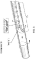
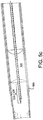
- a piercing system 310 (also 510 and 710 in FIGs. 5 and 7 respectively) comprises an elongate member 320 slidably housed within and supported by a piercing catheter 330.
- Piercing system 310 may be structurally and/or materially configured to cross an occlusion 305 within a vessel 300 by applying a continuous or intermittent longitudinal force or rotational (torquing) movement at the proximal end of at least one of elongate member 320 and piercing catheter 330.
- piercing catheter 330 is configured to pierce and penetrate occlusion 305.
- piercing catheter 330 has a shape and/or stiffness sufficient to pierce and penetrate occlusion 305 (or alternatively, through vessel walls), while in other embodiments, piercing catheter 330 is configured to microdissect occlusion 305.
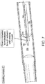
- FIG. 7 illustrates an exemplary embodiment of a piercing catheter microdissecting an occlusion.
- piercing catheter 330 may comprise a hollow chisel 331 having a tip 332 and being coupled to the distal end of a hollow member 333.
- hollow means a passage or space therein which can allow the passage of another object.
- a plurality of hollow chisel 331, tip 332 and hollow member 333 may be comprised of the same material (e.g., cut from a single tube or formed in a common mold).
- any of hollow chisel 331, tip 332 and hollow member 333 and/or the piercing catheter 330 may be coated with an ePTFE film.
- elongate member 320 is slidably housed within and supported by hollow member 333.
- elongate member 320 is axially movable along the longitudinal axis of hollow member 333 and hollow chisel 331 such that tip 332 is laterally displaced by axial displacement of elongate member 320, for instance, axial displacement on the order of 1mm.
- tip 332 may be laterally displaced (e.g., opened and closed or any position in between) in response to selective axial displacement of elongate member 320, between a first position, in which tip 332 is disposed proximal to the axis, and a second position, in which tip 332 is generally radially spaced apart from the first position.
- FIG. 6 illustrates an embodiment 630 with the hollow chisel 631 and tip 632 of hollow member 633 in a second position (with elongate member 620 moved distally) and
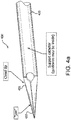
- FIG. 4a illustrates an embodiment 430 with the tip 432 in a first position.
- hollow member 333 is an elongate member, as that term has been defined herein, configured to house elongate member 320 along its longitudinal axis.
- the outer diameter of hollow member 333 should permit its passage through lumen of vessel 300 and the inner diameter of hollow member 333 should permit passage of elongate member 320.
- the outer diameter of hollow member 333 is from about 0.015 (0.381mm) to about 0.055 inches (1.397mm) more preferably from about 0.025 (0.635mm) to about 0.045 inches (1.143mm) and most preferably about 0.035 inches (0.889mm).
- the inner diameter of hollow member 333 is from about 0.006 (0.1524mm) to about 0.022 inches (0.5588mm), more preferably from about 0.010 (0.254mm) to about 0.016 inches (0.4064mm), and most preferably about 0.016 inches (0.4064mm).
- hollow chisel 331 is coupled to the distal end of hollow member 333.
- the coupling may occur at or near the point of articulation of tip 332 or further down a chisel shaft (not shown) of hollow chisel 331.
- an outer surface of the chisel shaft may be spiral-cut for added flexibility, for example, starting at from about 2 to about 3mm proximal to the point of articulation of tip 332.
- the dimensions of hollow chisel 331 at its proximal end may be larger or smaller than the dimensions of hollow member 333 at its distal end. That being said, in a preferred embodiment, the diameters are substantially the same to generally align the longitudinal axes for elongate member 320 to travel.
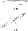
- Fig 4b flexibility of the distal region of the hollow member 433 has been improved by cutting openings through hollow member 433.
- the cut pattern is a series of semi-circular kerfs 450 laid out in a helical pattern on the distal end of the catheter.
- length of the semi-circular kerfs 450 is shortened toward the proximal end of the helical pattern. This serves as a strain relief.
- cut shapes are possible. These include straight kerfs and rectangular or partial rectangular kerfs.
- hollow member 433 may be altered (alone or in combination with placement of kerfs 450) by varying the wall thickness of member 433 and/or varying the thermal treatment applied to hollow member. As is known in the art, heat treatment of metals may alter their flexibility.
- tip 432 may possess different shapes. For example, tip 432 may feature a pointed terminal end such as that shown in Fig. 4a . In certain embodiments, tip 432 may have a more rounded end.
- hollow member 433 may comprise different shaped terminal ends on both its ends. Such configurations allow the clinician to choose tip end shape or change the tip used during a procedure by removing hollow member 433 and inserting the opposite end of hollow member 433.
- tip 332 comprises one or a plurality of separate elements at its distal end, at least one of which is moveable in response to selective axial displacement of elongate member 320.
- tip 332 may comprise one, two, three, four, five, six or any other suitable number of separate elements at its distal end.
- such separate elements may emanate from a unitary structure such as a ring at or near its proximal end.
- Tip 332 itself may be generally smooth or modified with serrations, barbs, hooks, anchors or the like.
- tip 332 may taper or otherwise come to a sharp point, a straight wedge, a curved wedge, or any other end that facilitates piercing and/or penetrating occlusion 305.
- Tip 332 may be comprised of a shape memory material such as nitinol to facilitate its articulation.
- the shape memory material may permit the tip to regain its closed position form after withdrawal of elongate member 320 from its lumen.
- Other modes of tip reformation could be through a spring-loaded micro hinge, a collapsible mesh, or any other structures which permit the tip to regain its closed position form upon withdrawal of elongate member 320 from its lumen.
- said shape memory alloy is selected from the group consisting of spring steel, Eligloy and carbon fiber composite.
- tip 332 is biased in a closed position when elongate member 320 is withdrawn out of the lumen of hollow chisel 331.
- elongate member 320 is reciprocated in and out of the lumen of hollow chisel 331 to articulate tip 332 between a closed tip and an open tip configuration, for example, to perform micro-dissection.
- the closed and open configurations could alternate between a sharp tip and a blunt tip, respectively, or any shaped tip which facilitates micro-dissection.
- said elongate member is reciprocated manually or automatically using a device that attaches to the elongate member and reciprocates said elongate member.
- Exemplary embodiments of the present invention provide reentry systems configured to bypass an occlusion.
- exemplary embodiments of the present invention provide reentry systems configured to cross an occlusion as described above, and also to bypass an occlusion in the event crossing by piercing and penetrating is unsuccessful.
- Bypassing an occlusion in exemplary embodiments comprises sub-intimal dissection.
- embodiments of the present invention may facilitate initial entry or reentry of an elongate member into a vessel or other anatomical feature,
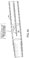
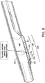
- a reentry system 850 comprises an elongate member 820 optionally disposed within and moveable along the longitudinal axis and through the lumen of a piercing catheter 830, and a reentry catheter 840.
- Reentry catheter 840 in turn comprises a side port 841 and a ramp 842, both near its distal end, optionally an outer ring 843, and a hollow member 844, wherein at least one of elongate member 820 and piercing catheter 830 is disposed within and moveable along the longitudinal axis and through the lumen of outer ring 843 and hollow member 844 and can be directed to exit through side port 841 by way of ramp 842.
- the length between the distal tip of reentry catheter 840 and the distal edge of side port 841 may be varied as clinically required.
- the stiffness and "torqueability" of reentry catheter 840 may be varied by altering the strength of its materials, the coil configuration (if it is of coiled construction), the braid angle and/or the pick count (if it is of braided construction), and/or by using more or less overwrapping material.
- side-port 841 remains blocked by ramp 842 when at least one of elongate member 820 and piercing catheter 830 is disposed within reentry system 850 and extends distal to side-port 841.
- ramp 842 is actuated thereby opening side port 841 and presenting ramp 842 to direct reentry of elongate member 820 and piercing catheter 830 back into the lumen of a vessel 800 from the sub-intimal space following sub-intimal dissection.
- Sub-intimal dissection may be performed by techniques known to those skilled in the art using elongate member 820 or piercing catheter 830.
- elongate member 820 may comprise a flexible distal end configured to fold over on itself upon meeting resistance from an occlusion 805 and be displaced laterally into the sub-intimal space for sub-intimal dissection.
- ramp 842 is maintained in a blocking configuration by one of elongate member 820 and piercing catheter 830 but is biased to actuate and drop to present itself for directing reentry.
- bias may be accomplished using a shape memory material such as nitinol or any other material or device that permits ramp 842 to drop into its actuated configuration upon the withdrawal of elongate member 820, and piercing catheter 830 when present in exemplary embodiments, from the distal end of reentry catheter 840.
- side port 841 and ramp 842 are integral with hollow member 844.
- optional outer ring 843 integrally comprises side port 841 and ramp 842 (e.g., cut from a single tube or formed in a common mold) and circumscribes, or is otherwise coupled to the distal end of, hollow member 844.
- hollow member 844 is configured with its own respective side port on its distal end which is in turn aligned with side port 841.
- ramp 842 may drop into its actuated configuration upon the withdrawal of elongate member 820, and piercing catheter 830 when present in exemplary embodiments, from the distal end of reentry catheter 840.
- ramp 842 may be pivotally coupled to hollow member 844 within side port 841 to drop into its actuated configuration upon the withdrawal of elongate member 820 and piercing catheter 830 from the distal end of reentry catheter 840.
- Such embodiments may comprise a spring and/or a hinge.
- ramp 842 may be actuated mechanically. For example, ramp may be moved from its closed to open (i.e., angled) position by use of attached pull wires.
- ramp 842 may be actuated by axial motion between co-radial inner and outer tubes where one edge or portion of the ramp is attached to one tube and another edge or portion is attached to the other tube.
- such relative axial motion could be used to actuate a ramp with spring or memory characteristics whereby the ramp may be formed in the outer tube and upon removal of the inner tube proximate the ramp, the ramp moves into position.
- ramp 842 may be moved (or allowed to move) into place by torquing or twisting a co-radial tube assembly.
- ramp 842 may comprise an inflatable member, e.g., the ramp is allowed to move into position by either being forced into such position on inflation of a proximally-located bladder or the inverse, i.e., the ramp moves into position by deflation of such a bladder.
- ramp 842 may be comprised by the inflatable member itself.
- ramp 842 may be actuated hydraulically by directing a stream of fluid (e.g., saline) against some portion of the ramp.
- the angle of reentry relative to the longitudinal axis of the reentry catheter 840 may be varied by design to suit clinician preference. These preferences are typically driven by a clinician's desire to accomplish reentry without piercing the vessel wall across the lumen from the reentry site (a risk when reentry angles are high) and accuracy in reentry at a desired target (a challenge when angles are low).
- An angle between about 25 to about 50 degrees may be used in certain cases.
- An angle of between about 35 to about 45 degrees may be used for certain treatment procedures. In another embodiment, said angle is about 25, about 30, about 40, about 45, or about 50 degrees.
- the angle of reentry may result from one or more design factors. Angle of ramp 842 when moved into position is one such factor but another factor is the flexibility of hollow member 433 (as seen in FIG. 4b ) as described above.
- reentry catheter 840 should generally be sufficient to permit passage of elongate member 820 and optionally piercing catheter 830.
- reentry catheter 840 is configured to permit passage of an elongate member having an outer diameter of from about 0.010 to about 0.055" (0.254 to 1.4 mm) more preferably from about 0.025 to about 0.045" (0.635 to 1.14mm) and most preferably about 0.040" (1.016mm).
- the outer diameter of reentry system 850 is from about 0.025 to about 0.10" (0.635 to about 2.54mm) and more preferably about 0.05" (1.27mm).
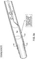
- an exemplary reentry system comprises any elongate member, as that term has been defined herein, disposed within and moveable along the longitudinal axis and through the lumen of a reentry catheter 1240.
- Reentry catheter 1240 in turn comprises a side port 1241 and a ramp 1242, both near its distal end, optionally an outer ring 1243, and a hollow member, wherein the elongate member is disposed within and moveable along the longitudinal axis and through the lumen of outer ring 1243 and hollow member 1244 and can be directed to exit through side port 1241 by way of ramp 1242.
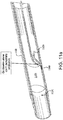
- FIGS. 11a-11g comprises a multi-lumen (i.e. dual-lumen) reentry catheter 1140 having a side-port 1141 and a ramp 1142 to guide reentry of an elongate member 1121 from a sub-intimal space 1180 following sub-intimal dissection.
- the reentry catheter lumens are separated by a tearable sheath 1160 which supports ramp 1142 in a partially actuated configuration, allowing undisturbed passage of a guidewire 1120 through one of the reentry catheter lumens.
- Tearable sheath 1160 may be a thin layer of ePTFE or any other tearable material capable of withstanding the downward force of ramp 1142 without tearing.
- ramp 1142 is not actuated by withdrawing guidewire 1120 from its respective catheter lumen in a proximal direction past side-port 1141 and ramp 1142.
- Ramp 1142 is fully actuated by advancing elongate member 1121 sufficient to tear tearable sheath 1160 (due to it having a larger diameter than guidewire 1120) and thereby remove the support for ramp 1142, whereupon elongate member 1121 can be withdrawn to allow full actuation and then advanced through side-port 1141 for reentry into a vessel 1100 from sub-intimal space 1180.
- an optional outer ring 1143 integrally comprises side port 1141 and ramp 1142 (e.g., cut from a single tube or formed in a common mold) and circumscribes, or is otherwise coupled to the distal end of, multi-lumen reentry catheter 1140.
- multi-lumen reentry catheter 1140 is configured with its own respective side port on its distal end which is in turn aligned with side port 1141.
- ramp 1142 may drop into its actuated configuration upon the withdrawal of elongate member 1120, and piercing catheter 1130 when present in exemplary embodiments, from the distal end of multi-lumen reentry catheter 1140.
- a method of using a device such as described herein comprises the steps of inserting an elongate member into an occluded vessel proximate an occlusion; advancing a piercing catheter over the elongate member to a position proximate the distal end of the elongate member; and applying a longitudinal force to advance the elongate member into the occlusion.
- the piercing catheter when it is proximal to the elongate member, it serves to support the elongate member so that it has sufficient stiffness to cross the occlusion.
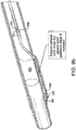
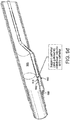
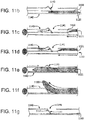
- a method comprises the steps of inserting an elongate member 520 into an occluded vessel proximate an occlusion 505; advancing a piercing catheter 530 over the elongate member 520 to a position beyond the distal end of the elongate member 520 such that a tip 532 is formed at the distal end of the piercing catheter 530, and applying a longitudinal force to advance the piercing catheter 530 into the occlusion 505.
- a further embodiment involves reciprocating the elongate member 520 in and out of the chisel's 531 distal end to actuate the chisel 531 between an open tip (See FIG.
- tip 532 is used to pierce the fibrous cap of the occlusion then elongate member 520 (i.e. a guidewire) is pushed through the rest of the occlusion.
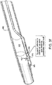
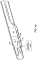
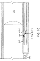
- the present invention comprises the steps of inserting an elongate member 920 into an occluded vessel 900 proximate an occlusion 905; advancing the elongate member 920 into the sub-intimal space 980 of the occluded vessel 900 so the distal end of the elongate member 920 has bypassed the occlusion 905; advancing a piercing catheter 930 over the elongate member 920 to a position proximate the distal end of the elongate member 920; advancing a reentry catheter 940 over the piercing catheter 930; retracting the elongate member 920 and piercing catheter 930 to actuate the ramp 942 and; applying a longitudinal force to advance the piercing catheter 930 up the ramp 942 to re-enter the occluded vessel 900 on the distal side of the occlusion 905.
- the present disclosure comprises the steps of inserting a guidewire 1120 into an occluded vessel 1100 proximate an occlusion 1105; advancing the guidewire into the sub-intimal space 1180 of the occluded vessel 1105 so the distal end 1170 of the elongate member 1120 has bypassed the occlusion 1105; advancing a reentry catheter 1140 with a tearable sheath 1160 over the elongate member 1120 so that the reentry catheter's 1140 distal end is proximate the distal end of the elongate member 1120; withdrawing the guidewire 1120; advancing a larger elongate member 1121 distal the side-port and thereby tearing the tearable sheath 1160; withdrawing the larger elongate member 1121 proximal the side-port 1141 and thereby actuating the ramp 1142; and applying a longitudinal force to advance the larger
- yet another exemplary embodiment comprises the steps of applying a longitudinal force to advance a piercing catheter through any anatomical feature, wherein the piercing catheter comprises: an elongate member; a hollow chisel with proximal and distal ends, wherein the distal end actuates between an open and closed position; wherein the distal end opens when the elongate member passes through the distal end; and wherein the distal end closes to form the tip when the elongate member is removed from the distal end; and a catheter with its distal end attached to the chisel's proximate end such that the catheter and the chisel circumscribe the elongate member.
- Yet another exemplary method comprises an attempted crossing of an occlusion through the lumen of the occluded vessel and abandoning the cross approach and instead performing a sub-intimal dissection to bypass the occlusion.
- An embodiment may comprise inserting an elongate member into an occluded vessel proximate an occlusion; advancing a piercing catheter over the elongate member to a position beyond the distal end of the elongate member such that a tip is formed at the distal end of the piercing catheter; applying a longitudinal force to advance the piercing catheter into the occlusion; withdrawing the piercing catheter proximal the distal end of the elongate member; advancing the elongate member into the sub-intimal space of the occluded vessel distal the occlusion; advancing a piercing catheter over the elongate member to a position proximate the distal end of the elongate member; advancing a reentry
- catheters, piercing catheters, reentry catheters and the like referenced herein may incorporate any of the various aspects described.
- other embodiments comprise using devices and methods described herein to perforate and exit the vessel completely through the perforation site and creating a bypass in neighboring vessel or tissue.
- Other embodiments comprise using devices and methods described herein to pierce grafts or stent-grafts to create fenestrations. Fenestrations to host vessels and/or indwelling devices (grafts and stent-grafts) could be facilitated with this system.
- the flexible nature of the puncturing tool allows for easy and accurate deflection from the host lumen to the vessel wall.
- said medical device has a method of buttressing said device against a vessel, stent and/or stent-graft in order to generate enough force to pierce said vessel, stent, and/or stent-graft.
- Traversing tissue may require the clinician to use some mode of imaging (Ultrasound / Angiography, in which case, the puncturing tool would be configured to be echogenic or radiopaque.
- Still other embodiments may include various coatings to the various structures described herein, such as for example, ePTFE, Heparin, or the like.
- the medical device may comprise an echogenic and/or radio-opaque material permitting visualizing by medical imagery, particularly by ultrasound and/or radiography, the position of the medical device.
- the echogenic portion includes an echogenic material comprising a plastic impregnated with sonically reflective particles.
- Radiopaque markers or similar indicia are often used to allow the medical staff to exactly position the medical device using the imagining technology.
- the system may include some type of radiopaque marker to allow the physician performing the procedure to monitor the progress of the system through the body.
- the system may contain either radiopaque markers or contain radiopaque materials commonly known in the art.
- the markings may also include a radiopaque material to aid in non-invasive visualization or other suitable visualization materials as known in the art.
- radiopaque metallic fibers such as gold, platinum, platinum-tungsten, palladium, platinum-iridium, rhodium, tantalum, or alloys or composites of these metals like may be incorporated into the device, particularly, into the graft, to allow fluoroscopic visualization of the device.
- the systems and methods described herein may be useful in connection with the treatment of coronary artery disease, peripheral vascular diseases, portal hypertension, carotid artery disease, renal vascular hypertension, occlusion of the iliac vessels, subintimal angioplasty (as described in Bolia, et al. Cardiovasc. Intervent. Radiol., 13, 357-363, (1990 )), biopsies, and in situ fenestration of other tissues, amongst other conditions affecting anatomical conduits.
- the present invention may also be useful to pierce grafts or stent-grafts to create fenestrations and to create anatomical passages such as an arterio-venous fistula.
Landscapes
- Health & Medical Sciences (AREA)
- Life Sciences & Earth Sciences (AREA)
- General Health & Medical Sciences (AREA)
- Veterinary Medicine (AREA)
- Engineering & Computer Science (AREA)
- Biomedical Technology (AREA)
- Heart & Thoracic Surgery (AREA)
- Public Health (AREA)
- Animal Behavior & Ethology (AREA)
- Surgery (AREA)
- Anesthesiology (AREA)
- Hematology (AREA)
- Pulmonology (AREA)
- Biophysics (AREA)
- Vascular Medicine (AREA)
- Nuclear Medicine, Radiotherapy & Molecular Imaging (AREA)
- Medical Informatics (AREA)
- Molecular Biology (AREA)
- Orthopedic Medicine & Surgery (AREA)
- Media Introduction/Drainage Providing Device (AREA)
- Surgical Instruments (AREA)
Claims (10)
- Système de dispositif médical (310, 510, 710) conçu pour un déploiement endoluminal, le système comprenant :un cathéter de perçage (330, 430, 530, 630, 1130) comprenant un ciseau creux (331, 531) possédant un passage de ciseau (333, 433, 633) dans celui-ci avec une extrémité proximale, une extrémité distale et une pointe (332, 432, 532, 632) au niveau de l'extrémité distale, ladite pointe étant adaptée pour effectuer une transition entre une configuration de pointe fermée et une configuration de pointe ouverte ;un élément allongé (320, 520, 620, 920, 1120) possédant une extrémité distale émoussée et pouvant être déplacé le long de l'axe longitudinal du cathéter de perçage pour actionner le ciseau creux entre les configurations de pointe fermée et de pointe ouverte ;et un cathéter de rentrée (840, 940, 1240) comprenant un orifice latéral (841, 1141, 1241) proche de l'extrémité distale, ledit cathéter de perçage ou ledit élément allongé pouvant se déplacer à travers l'orifice latéral.
- Système de dispositif médical (310, 510, 710) selon la revendication 1, ledit cathéter de rentrée comprenant une rampe (842, 942, 1142, 1242) près de l'extrémité distale, lorsque la rampe n'est pas actionnée, ledit orifice latéral étant fermé et lorsque la rampe est actionnée, ledit orifice latéral s'ouvrant et ladite rampe étant présentée pour diriger le cathéter de perçage ou l'élément allongé à travers l'orifice latéral.
- Système de dispositif médical (310, 510, 710) selon la revendication 2, ladite rampe n'étant pas actionnée lorsque les extrémités distales de l'élément allongé et du cathéter de perçage sont distales par rapport à l'orifice latéral, et ladite rampe étant actionnée lorsque les extrémités distales de l'élément allongé et du cathéter de perçage sont situés à proximité de l'orifice latéral.
- Système de dispositif médical (310, 510, 710) selon la revendication 1, lorsqu'un élément allongé est poussé à travers l'extrémité distale du cathéter de perçage et hors de celle-ci, ledit cathéter de perçage devenant un cathéter de support.
- Système de dispositif médical (310, 510, 710) selon l'une quelconque des revendications précédentes, ledit cathéter de perçage comprenant un cathéter avec des extrémités proximale et distale ;
et ladite extrémité proximale de ciseau creux étant proche de l'extrémité distale du cathéter, ladite pointe étant mobile, en réponse au déplacement axial sélectif de l'élément allongé, entre une première position, dans laquelle la pointe est disposée à proximité de l'axe, et une seconde position, dans laquelle la pointe est espacée de la première position. - Système de dispositif médical (310, 510, 710) selon la revendication 5, ledit élément allongé étant retiré du passage de ciseau et ledit ciseau étant actionné pour former une pointe tranchante.
- Système de dispositif médical (310, 510, 710) selon la revendication 4, ledit cathéter de support possédant une section transversale sensiblement arrondie le long de sa longueur.
- Système de dispositif médical (310, 510, 710) selon la revendication 1, ladite rampe comprenant un matériau à mémoire de forme.
- Système de dispositif médical (310, 510, 710) selon la revendication 8, ledit matériau à mémoire de forme étant du nitinol.
- Système de dispositif médical (310, 510, 710) selon la revendication 1, ledit élément allongé étant un fil métallique de guidage (1120), un cathéter ou une fibre.
Applications Claiming Priority (4)
| Application Number | Priority Date | Filing Date | Title |
|---|---|---|---|
| US39428610P | 2010-10-18 | 2010-10-18 | |
| US13/273,111 US8932315B2 (en) | 2010-10-18 | 2011-10-13 | Systems and methods for percutaneous occlusion crossing |
| EP11775878.9A EP2629826B1 (fr) | 2010-10-18 | 2011-10-14 | Systèmes de croisement d'occlusions percutanées |
| PCT/US2011/056434 WO2012054349A2 (fr) | 2010-10-18 | 2011-10-14 | Systèmes et procédés de croisement d'occlusions percutanées |
Related Parent Applications (2)
| Application Number | Title | Priority Date | Filing Date |
|---|---|---|---|
| EP11775878.9A Division EP2629826B1 (fr) | 2010-10-18 | 2011-10-14 | Systèmes de croisement d'occlusions percutanées |
| EP11775878.9A Division-Into EP2629826B1 (fr) | 2010-10-18 | 2011-10-14 | Systèmes de croisement d'occlusions percutanées |
Publications (3)
| Publication Number | Publication Date |
|---|---|
| EP2823848A2 EP2823848A2 (fr) | 2015-01-14 |
| EP2823848A3 EP2823848A3 (fr) | 2015-07-08 |
| EP2823848B1 true EP2823848B1 (fr) | 2019-11-27 |
Family
ID=45934765
Family Applications (2)
| Application Number | Title | Priority Date | Filing Date |
|---|---|---|---|
| EP14181675.1A Active EP2823848B1 (fr) | 2010-10-18 | 2011-10-14 | Systèmes de croisement d'occlusion percutanée |
| EP11775878.9A Active EP2629826B1 (fr) | 2010-10-18 | 2011-10-14 | Systèmes de croisement d'occlusions percutanées |
Family Applications After (1)
| Application Number | Title | Priority Date | Filing Date |
|---|---|---|---|
| EP11775878.9A Active EP2629826B1 (fr) | 2010-10-18 | 2011-10-14 | Systèmes de croisement d'occlusions percutanées |
Country Status (10)
| Country | Link |
|---|---|
| US (2) | US8932315B2 (fr) |
| EP (2) | EP2823848B1 (fr) |
| JP (1) | JP5902700B2 (fr) |
| CN (1) | CN103260689B (fr) |
| AU (1) | AU2011318273B2 (fr) |
| CA (2) | CA2814359C (fr) |
| ES (1) | ES2537266T3 (fr) |
| HK (2) | HK1185025A1 (fr) |
| RU (1) | RU2013122868A (fr) |
| WO (1) | WO2012054349A2 (fr) |
Families Citing this family (40)
| Publication number | Priority date | Publication date | Assignee | Title |
|---|---|---|---|---|
| US10888354B2 (en) * | 2006-11-21 | 2021-01-12 | Bridgepoint Medical, Inc. | Endovascular devices and methods for exploiting intramural space |
| US8591527B2 (en) * | 2011-04-25 | 2013-11-26 | Smith & Nephew, Inc. | Suture passer with suture capturing articulating jaw at distal end for suturing in arthroscopic surgery |
| US20120283775A1 (en) * | 2011-05-06 | 2012-11-08 | Edward H Cully | Echogenic Sleeve |
| WO2013022796A2 (fr) | 2011-08-05 | 2013-02-14 | Silk Road Medical, Inc. | Procédés et systèmes de traitement d'un accident ischémique cérébral aigu |
| US10779855B2 (en) | 2011-08-05 | 2020-09-22 | Route 92 Medical, Inc. | Methods and systems for treatment of acute ischemic stroke |
| CN104812325A (zh) * | 2012-09-26 | 2015-07-29 | 波士顿科学国际有限公司 | 用于肾神经消融支持多个电极的具有肋脊结构的导管 |
| EP2948209B1 (fr) * | 2013-01-22 | 2018-11-21 | Anuncia, Inc. | Dispositif rinçage d'un système de dérivation |
| US9301777B2 (en) | 2013-07-29 | 2016-04-05 | Invatec S.P.A. | Occlusion bypassing apparatuses and methods for bypassing an occlusion in a blood vessel |
| US9308356B2 (en) | 2013-07-29 | 2016-04-12 | Invatec S.P.A. | Occlusion bypassing apparatuses and methods for bypassing an occlusion in a blood vessel |
| US9364642B2 (en) | 2013-08-14 | 2016-06-14 | Invatec S.P.A. | Balloon catheter systems and methods for bypassing an occlusion in a blood vessel |
| US9320874B2 (en) | 2013-08-15 | 2016-04-26 | Invatec S.P.A. | Catheter systems with a blocking mechanism and methods for bypassing an occlusion in a blood vessel |
| US9265512B2 (en) | 2013-12-23 | 2016-02-23 | Silk Road Medical, Inc. | Transcarotid neurovascular catheter |
| US9446222B2 (en) | 2014-03-05 | 2016-09-20 | Invatec S.P.A. | Catheter assemblies and methods for stabilizing a catheter assembly within a subintimal space |
| US9820761B2 (en) | 2014-03-21 | 2017-11-21 | Route 92 Medical, Inc. | Rapid aspiration thrombectomy system and method |
| US9241699B1 (en) | 2014-09-04 | 2016-01-26 | Silk Road Medical, Inc. | Methods and devices for transcarotid access |
| WO2015161306A1 (fr) | 2014-04-18 | 2015-10-22 | Alcyone Lifesciences, Inc. | Systèmes et procédés de dérivation d'un fluide |
| US10391282B2 (en) | 2014-07-08 | 2019-08-27 | Teleflex Innovations S.À.R.L. | Guidewires and methods for percutaneous occlusion crossing |
| US10456557B2 (en) | 2014-08-14 | 2019-10-29 | Invatec S.P.A. | Occlusion bypassing apparatus with varying flexibility and methods for bypassing an occlusion in a blood vessel |
| EP3182920B1 (fr) * | 2014-08-21 | 2024-03-13 | Koninklijke Philips N.V. | Dispositif pour traverser des occlusions |
| US11027104B2 (en) | 2014-09-04 | 2021-06-08 | Silk Road Medical, Inc. | Methods and devices for transcarotid access |
| US11065019B1 (en) | 2015-02-04 | 2021-07-20 | Route 92 Medical, Inc. | Aspiration catheter systems and methods of use |
| ES2770321T3 (es) | 2015-02-04 | 2020-07-01 | Route 92 Medical Inc | Sistema de trombectomía por aspiración rápida |
| WO2017019563A1 (fr) | 2015-07-24 | 2017-02-02 | Route 92 Medical, Inc. | Système et procédés de distribution d'ancrage |
| WO2017019564A1 (fr) | 2015-07-24 | 2017-02-02 | Route 92 Medical, Inc. | Procédés de pose d'implant intracrânien |
| US10172632B2 (en) | 2015-09-22 | 2019-01-08 | Medtronic Vascular, Inc. | Occlusion bypassing apparatus with a re-entry needle and a stabilization tube |
| US10327791B2 (en) | 2015-10-07 | 2019-06-25 | Medtronic Vascular, Inc. | Occlusion bypassing apparatus with a re-entry needle and a distal stabilization balloon |
| JP7111621B2 (ja) * | 2016-01-01 | 2022-08-02 | トラクタス ヴァスキュラー,エルエルシー | 可撓性カテーテル |
| CA3011238C (fr) * | 2016-01-15 | 2024-01-02 | Tva Medical, Inc. | Dispositifs et procedes pour faire avancer un fil |
| JP2019530539A (ja) | 2016-10-13 | 2019-10-24 | アルキオーネ・ライフサイエンシズ・インコーポレイテッドAlcyone Lifesciences, Inc. | シャントフラッシャおよび関連方法 |
| EP3568186B1 (fr) | 2017-01-10 | 2022-09-14 | Route 92 Medical, Inc. | Systèmes de cathéters d'aspiration |
| CN110461401B (zh) | 2017-01-20 | 2022-06-07 | 92号医疗公司 | 单操作者颅内医疗装置输送系统和使用方法 |
| US11173281B2 (en) | 2017-06-19 | 2021-11-16 | W. L. Gore & Associates, Inc. | Fenestration devices, systems, and methods |
| US10722252B2 (en) | 2017-10-26 | 2020-07-28 | Teleflex Life Sciences Limited | Subintimal catheter device, assembly and related methods |
| WO2019209798A1 (fr) * | 2018-04-24 | 2019-10-31 | Asahi Intecc Co., Ltd. | Cathéter de ré-entrée et procédés d'utilisation associés |
| JP2021523793A (ja) | 2018-05-17 | 2021-09-09 | ルート92メディカル・インコーポレイテッドRoute 92 Medical, Inc. | 吸引カテーテルシステム及び使用方法 |
| US10667833B2 (en) * | 2018-06-08 | 2020-06-02 | Neuravi Limited | Guidewire with an atraumatic clot-circumventing configured distal end for use in an endovascular medical system |
| CN109330636B (zh) * | 2018-07-27 | 2019-10-22 | 尚华 | 一种血管内记忆金属穿刺系统及其应用方法 |
| EP3946540A4 (fr) | 2019-04-05 | 2023-04-12 | Traverse Vascular, Inc. | Cathéters de rentrée pour traverser des occlusions totales chroniques |
| CN114728148A (zh) * | 2019-08-13 | 2022-07-08 | 瑞弗罗医疗公司 | 再进入导管 |
| WO2022115193A1 (fr) * | 2020-11-24 | 2022-06-02 | RampTech, LLC | Systèmes et procédés de restauration de la perméabilité à travers une obstruction |
Family Cites Families (40)
| Publication number | Priority date | Publication date | Assignee | Title |
|---|---|---|---|---|
| US4774949A (en) | 1983-06-14 | 1988-10-04 | Fogarty Thomas J | Deflector guiding catheter |
| US4552554A (en) | 1984-06-25 | 1985-11-12 | Medi-Tech Incorporated | Introducing catheter |
| US4898575A (en) | 1987-08-31 | 1990-02-06 | Medinnovations, Inc. | Guide wire following tunneling catheter system and method for transluminal arterial atherectomy |
| US5389087A (en) * | 1991-09-19 | 1995-02-14 | Baxter International Inc. | Fully exchangeable over-the-wire catheter with rip seam and gated side port |
| US5595186A (en) * | 1992-04-06 | 1997-01-21 | Alan I. Rubinstein | Bone marrow biopsy needle |
| US5538504A (en) | 1992-07-14 | 1996-07-23 | Scimed Life Systems, Inc. | Intra-extravascular drug delivery catheter and method |
| US5364376A (en) * | 1992-08-04 | 1994-11-15 | Danforth Biomedical Incorporated | Convertible catheter |
| US5243997A (en) | 1992-09-14 | 1993-09-14 | Interventional Technologies, Inc. | Vibrating device for a guide wire |
| WO1997013463A1 (fr) | 1995-10-13 | 1997-04-17 | Transvascular, Inc. | Methodes et appareils pour le pontage d'obstructions arterielles, et/ou servant a effectuer d'autres interventions transvasculaires |
| JPH11513577A (ja) * | 1995-10-13 | 1999-11-24 | トランスバスキュラー インコーポレイテッド | 組織間経管インターベンションのための装置、システム及び方法 |
| US6302875B1 (en) | 1996-10-11 | 2001-10-16 | Transvascular, Inc. | Catheters and related devices for forming passageways between blood vessels or other anatomical structures |
| US6375615B1 (en) | 1995-10-13 | 2002-04-23 | Transvascular, Inc. | Tissue penetrating catheters having integral imaging transducers and their methods of use |
| US6283983B1 (en) | 1995-10-13 | 2001-09-04 | Transvascular, Inc. | Percutaneous in-situ coronary bypass method and apparatus |
| US6726677B1 (en) | 1995-10-13 | 2004-04-27 | Transvascular, Inc. | Stabilized tissue penetrating catheters |
| US6217549B1 (en) | 1997-02-28 | 2001-04-17 | Lumend, Inc. | Methods and apparatus for treating vascular occlusions |
| US6217527B1 (en) * | 1998-09-30 | 2001-04-17 | Lumend, Inc. | Methods and apparatus for crossing vascular occlusions |
| US6231546B1 (en) | 1998-01-13 | 2001-05-15 | Lumend, Inc. | Methods and apparatus for crossing total occlusions in blood vessels |
| US20050171478A1 (en) * | 1998-01-13 | 2005-08-04 | Selmon Matthew R. | Catheter system for crossing total occlusions in vasculature |
| US20070265563A1 (en) | 2006-05-11 | 2007-11-15 | Heuser Richard R | Device for treating chronic total occlusion |
| US6248081B1 (en) * | 1999-09-28 | 2001-06-19 | Scimed Life Systems, Inc. | Endoscopic submucosal core biopsy device |
| JP3790074B2 (ja) * | 1999-10-26 | 2006-06-28 | オリンパスメディカルシステムズ株式会社 | 内視鏡用マーキング装置 |
| US6464665B1 (en) | 2000-07-05 | 2002-10-15 | Richard R. Heuser | Catheter apparatus and method for arterializing a vein |
| AU2002235159A1 (en) * | 2000-12-05 | 2002-06-18 | Lumend, Inc. | Catheter system for vascular re-entry from a sub-intimal space |
| WO2002064020A2 (fr) | 2001-02-13 | 2002-08-22 | Lumend, Inc. | Procede et appareil de micro-dissection d'occlusions vasculaires |
| US6997903B2 (en) | 2003-02-10 | 2006-02-14 | Bandula Wijay | Local drug delivery catheter |
| ATE386569T1 (de) | 2003-03-13 | 2008-03-15 | Medtronic Vascular Inc | Optisch geführte penetrationskatheter und ihre anwendungsverfahren |
| US8246640B2 (en) * | 2003-04-22 | 2012-08-21 | Tyco Healthcare Group Lp | Methods and devices for cutting tissue at a vascular location |
| US7276064B2 (en) | 2004-05-27 | 2007-10-02 | St. Jude Medical, Atrial Fibrillation Division, Inc. | Side-port sheath for catheter placement and translation |
| US20070088230A1 (en) | 2005-09-06 | 2007-04-19 | Fmd Co., Ltd | Medical instrument and medical equipment for treatment, and rotational handle device |
| EP4292548A3 (fr) | 2005-09-12 | 2024-02-28 | Boston Scientific Scimed, Inc. | Dispositifs endovasculaires |
| US20070083215A1 (en) | 2005-10-07 | 2007-04-12 | Hamer Rochelle M | Conduit for interventional procedures |
| EP1991141A4 (fr) | 2006-02-22 | 2013-09-18 | Strauss Bradley H | Manchon fil-guide pour faciliter la traversée d'une lésion |
| US20070244440A1 (en) * | 2006-03-28 | 2007-10-18 | Cook Incorporated | Medical device with expandable tip |
| WO2008006111A2 (fr) | 2006-07-07 | 2008-01-10 | The Spectranetics Corporation | cathéter de support À lumière unique pour un échange rapide et l'utilisation par fil |
| US9060802B2 (en) | 2006-11-21 | 2015-06-23 | Bridgepoint Medical, Inc. | Endovascular devices and methods for exploiting intramural space |
| US8282648B2 (en) * | 2007-12-19 | 2012-10-09 | Cook Medical Technologies Llc | Bone cement needle |
| EP2259830B1 (fr) | 2008-02-05 | 2017-08-16 | Bridgepoint Medical, Inc. | D'occlusions au niveau du croisement dans des vaisseaux sanguins |
| US20090281564A1 (en) | 2008-05-09 | 2009-11-12 | Cook Incorporated | Pre-Clot Vessel Dilator |
| US8449478B2 (en) * | 2008-05-16 | 2013-05-28 | Conquest Medical Technologies | Biopsy device |
| US8241311B2 (en) * | 2009-12-15 | 2012-08-14 | Medtronic Vascular, Inc. | Methods and systems for bypassing an occlusion in a blood vessel |
-
2011
- 2011-10-13 US US13/273,111 patent/US8932315B2/en active Active
- 2011-10-14 AU AU2011318273A patent/AU2011318273B2/en not_active Ceased
- 2011-10-14 ES ES11775878.9T patent/ES2537266T3/es active Active
- 2011-10-14 CN CN201180060638.9A patent/CN103260689B/zh active Active
- 2011-10-14 EP EP14181675.1A patent/EP2823848B1/fr active Active
- 2011-10-14 CA CA2814359A patent/CA2814359C/fr active Active
- 2011-10-14 JP JP2013534977A patent/JP5902700B2/ja active Active
- 2011-10-14 RU RU2013122868/14A patent/RU2013122868A/ru not_active Application Discontinuation
- 2011-10-14 WO PCT/US2011/056434 patent/WO2012054349A2/fr active Application Filing
- 2011-10-14 EP EP11775878.9A patent/EP2629826B1/fr active Active
- 2011-10-14 CA CA2876704A patent/CA2876704A1/fr not_active Abandoned
-
2013
- 2013-11-11 HK HK13112612.8A patent/HK1185025A1/xx not_active IP Right Cessation
-
2014
- 2014-12-04 US US14/561,033 patent/US9402649B2/en active Active
-
2015
- 2015-05-21 HK HK15104858.6A patent/HK1204459A1/xx unknown
Non-Patent Citations (1)
| Title |
|---|
| None * |
Also Published As
| Publication number | Publication date |
|---|---|
| EP2629826A2 (fr) | 2013-08-28 |
| CA2814359A1 (fr) | 2012-04-26 |
| US8932315B2 (en) | 2015-01-13 |
| JP5902700B2 (ja) | 2016-04-13 |
| HK1204459A1 (en) | 2015-11-20 |
| EP2823848A2 (fr) | 2015-01-14 |
| EP2629826B1 (fr) | 2015-03-04 |
| AU2011318273B2 (en) | 2015-02-05 |
| US20120095485A1 (en) | 2012-04-19 |
| WO2012054349A3 (fr) | 2012-06-21 |
| CA2876704A1 (fr) | 2012-04-26 |
| US20150094747A1 (en) | 2015-04-02 |
| RU2013122868A (ru) | 2014-11-27 |
| ES2537266T3 (es) | 2015-06-05 |
| AU2011318273A1 (en) | 2013-05-02 |
| CA2814359C (fr) | 2015-12-01 |
| JP2013544561A (ja) | 2013-12-19 |
| CN103260689A (zh) | 2013-08-21 |
| EP2823848A3 (fr) | 2015-07-08 |
| CN103260689B (zh) | 2017-05-03 |
| WO2012054349A2 (fr) | 2012-04-26 |
| HK1185025A1 (en) | 2014-02-07 |
| US9402649B2 (en) | 2016-08-02 |
Similar Documents
| Publication | Publication Date | Title |
|---|---|---|
| EP2823848B1 (fr) | Systèmes de croisement d'occlusion percutanée | |
| US11607245B2 (en) | Endovascular devices and methods for exploiting intramural space | |
| US20210186560A1 (en) | Endovascular devices and methods for exploiting intramural space | |
| JP5356580B2 (ja) | 血管構造内の完全閉塞を横断するためのカテーテルシステム | |
| US20080154190A1 (en) | System and Method for Arterial Access | |
| CN111053593A (zh) | 可成形的重复进入装置及其系统和方法 | |
| AU2015200563A1 (en) | Systems and methods for percutaneous occlusion crossing | |
| CN117337157A (zh) | 用于治疗血栓形成的包括可扩张远侧端部的抽吸装置及其系统和方法 | |
| US20200269014A1 (en) | Axial sharp needle reentry device | |
| WO2022115193A1 (fr) | Systèmes et procédés de restauration de la perméabilité à travers une obstruction |
Legal Events
| Date | Code | Title | Description |
|---|---|---|---|
| 17P | Request for examination filed |
Effective date: 20140820 |
|
| AC | Divisional application: reference to earlier application |
Ref document number: 2629826 Country of ref document: EP Kind code of ref document: P |
|
| AK | Designated contracting states |
Kind code of ref document: A2 Designated state(s): AL AT BE BG CH CY CZ DE DK EE ES FI FR GB GR HR HU IE IS IT LI LT LU LV MC MK MT NL NO PL PT RO RS SE SI SK SM TR |
|
| PUAI | Public reference made under article 153(3) epc to a published international application that has entered the european phase |
Free format text: ORIGINAL CODE: 0009012 |
|
| RIC1 | Information provided on ipc code assigned before grant |
Ipc: A61M 25/06 20060101ALI20150127BHEP Ipc: A61B 5/145 20060101ALI20150127BHEP Ipc: A61M 25/00 20060101ALI20150127BHEP Ipc: A61M 25/01 20060101ALI20150127BHEP Ipc: A61B 1/32 20060101ALI20150127BHEP Ipc: A61B 5/02 20060101ALI20150127BHEP Ipc: A61B 17/00 20060101ALI20150127BHEP Ipc: A61M 29/00 20060101AFI20150127BHEP Ipc: A61B 17/22 20060101ALI20150127BHEP Ipc: A61B 17/3207 20060101ALI20150127BHEP |
|
| PUAL | Search report despatched |
Free format text: ORIGINAL CODE: 0009013 |
|
| AK | Designated contracting states |
Kind code of ref document: A3 Designated state(s): AL AT BE BG CH CY CZ DE DK EE ES FI FR GB GR HR HU IE IS IT LI LT LU LV MC MK MT NL NO PL PT RO RS SE SI SK SM TR |
|
| RIC1 | Information provided on ipc code assigned before grant |
Ipc: A61B 1/32 20060101ALI20150604BHEP Ipc: A61M 25/06 20060101ALI20150604BHEP Ipc: A61B 5/145 20060101ALI20150604BHEP Ipc: A61M 25/00 20060101ALI20150604BHEP Ipc: A61M 29/00 20060101AFI20150604BHEP Ipc: A61B 17/3207 20060101ALI20150604BHEP Ipc: A61M 25/01 20060101ALI20150604BHEP Ipc: A61B 17/22 20060101ALI20150604BHEP Ipc: A61B 17/00 20060101ALI20150604BHEP Ipc: A61B 5/02 20060101ALI20150604BHEP |
|
| REG | Reference to a national code |
Ref country code: HK Ref legal event code: DE Ref document number: 1204459 Country of ref document: HK |
|
| R17P | Request for examination filed (corrected) |
Effective date: 20160107 |
|
| RBV | Designated contracting states (corrected) |
Designated state(s): AL AT BE BG CH CY CZ DE DK EE ES FI FR GB GR HR HU IE IS IT LI LT LU LV MC MK MT NL NO PL PT RO RS SE SI SK SM TR |
|
| GRAP | Despatch of communication of intention to grant a patent |
Free format text: ORIGINAL CODE: EPIDOSNIGR1 |
|
| STAA | Information on the status of an ep patent application or granted ep patent |
Free format text: STATUS: GRANT OF PATENT IS INTENDED |
|
| INTG | Intention to grant announced |
Effective date: 20190704 |
|
| RIN1 | Information on inventor provided before grant (corrected) |
Inventor name: CULLY, EDWARD H Inventor name: BOLAND II, BRIAN R Inventor name: GOODMAN, PAUL D Inventor name: DUNCAN, JEFFREY B |
|
| GRAS | Grant fee paid |
Free format text: ORIGINAL CODE: EPIDOSNIGR3 |
|
| GRAA | (expected) grant |
Free format text: ORIGINAL CODE: 0009210 |
|
| STAA | Information on the status of an ep patent application or granted ep patent |
Free format text: STATUS: THE PATENT HAS BEEN GRANTED |
|
| AC | Divisional application: reference to earlier application |
Ref document number: 2629826 Country of ref document: EP Kind code of ref document: P |
|
| AK | Designated contracting states |
Kind code of ref document: B1 Designated state(s): AL AT BE BG CH CY CZ DE DK EE ES FI FR GB GR HR HU IE IS IT LI LT LU LV MC MK MT NL NO PL PT RO RS SE SI SK SM TR |
|
| REG | Reference to a national code |
Ref country code: GB Ref legal event code: FG4D |
|
| REG | Reference to a national code |
Ref country code: CH Ref legal event code: EP |
|
| REG | Reference to a national code |
Ref country code: AT Ref legal event code: REF Ref document number: 1206024 Country of ref document: AT Kind code of ref document: T Effective date: 20191215 |
|
| REG | Reference to a national code |
Ref country code: DE Ref legal event code: R096 Ref document number: 602011063727 Country of ref document: DE |
|
| REG | Reference to a national code |
Ref country code: IE Ref legal event code: FG4D |
|
| REG | Reference to a national code |
Ref country code: NL Ref legal event code: MP Effective date: 20191127 |
|
| REG | Reference to a national code |
Ref country code: LT Ref legal event code: MG4D |
|
| PG25 | Lapsed in a contracting state [announced via postgrant information from national office to epo] |
Ref country code: ES Free format text: LAPSE BECAUSE OF FAILURE TO SUBMIT A TRANSLATION OF THE DESCRIPTION OR TO PAY THE FEE WITHIN THE PRESCRIBED TIME-LIMIT Effective date: 20191127 Ref country code: GR Free format text: LAPSE BECAUSE OF FAILURE TO SUBMIT A TRANSLATION OF THE DESCRIPTION OR TO PAY THE FEE WITHIN THE PRESCRIBED TIME-LIMIT Effective date: 20200228 Ref country code: SE Free format text: LAPSE BECAUSE OF FAILURE TO SUBMIT A TRANSLATION OF THE DESCRIPTION OR TO PAY THE FEE WITHIN THE PRESCRIBED TIME-LIMIT Effective date: 20191127 Ref country code: NO Free format text: LAPSE BECAUSE OF FAILURE TO SUBMIT A TRANSLATION OF THE DESCRIPTION OR TO PAY THE FEE WITHIN THE PRESCRIBED TIME-LIMIT Effective date: 20200227 Ref country code: LV Free format text: LAPSE BECAUSE OF FAILURE TO SUBMIT A TRANSLATION OF THE DESCRIPTION OR TO PAY THE FEE WITHIN THE PRESCRIBED TIME-LIMIT Effective date: 20191127 Ref country code: FI Free format text: LAPSE BECAUSE OF FAILURE TO SUBMIT A TRANSLATION OF THE DESCRIPTION OR TO PAY THE FEE WITHIN THE PRESCRIBED TIME-LIMIT Effective date: 20191127 Ref country code: BG Free format text: LAPSE BECAUSE OF FAILURE TO SUBMIT A TRANSLATION OF THE DESCRIPTION OR TO PAY THE FEE WITHIN THE PRESCRIBED TIME-LIMIT Effective date: 20200227 Ref country code: LT Free format text: LAPSE BECAUSE OF FAILURE TO SUBMIT A TRANSLATION OF THE DESCRIPTION OR TO PAY THE FEE WITHIN THE PRESCRIBED TIME-LIMIT Effective date: 20191127 Ref country code: NL Free format text: LAPSE BECAUSE OF FAILURE TO SUBMIT A TRANSLATION OF THE DESCRIPTION OR TO PAY THE FEE WITHIN THE PRESCRIBED TIME-LIMIT Effective date: 20191127 |
|
| PG25 | Lapsed in a contracting state [announced via postgrant information from national office to epo] |
Ref country code: RS Free format text: LAPSE BECAUSE OF FAILURE TO SUBMIT A TRANSLATION OF THE DESCRIPTION OR TO PAY THE FEE WITHIN THE PRESCRIBED TIME-LIMIT Effective date: 20191127 Ref country code: HR Free format text: LAPSE BECAUSE OF FAILURE TO SUBMIT A TRANSLATION OF THE DESCRIPTION OR TO PAY THE FEE WITHIN THE PRESCRIBED TIME-LIMIT Effective date: 20191127 Ref country code: IS Free format text: LAPSE BECAUSE OF FAILURE TO SUBMIT A TRANSLATION OF THE DESCRIPTION OR TO PAY THE FEE WITHIN THE PRESCRIBED TIME-LIMIT Effective date: 20200327 |
|
| PG25 | Lapsed in a contracting state [announced via postgrant information from national office to epo] |
Ref country code: AL Free format text: LAPSE BECAUSE OF FAILURE TO SUBMIT A TRANSLATION OF THE DESCRIPTION OR TO PAY THE FEE WITHIN THE PRESCRIBED TIME-LIMIT Effective date: 20191127 |
|
| PG25 | Lapsed in a contracting state [announced via postgrant information from national office to epo] |
Ref country code: RO Free format text: LAPSE BECAUSE OF FAILURE TO SUBMIT A TRANSLATION OF THE DESCRIPTION OR TO PAY THE FEE WITHIN THE PRESCRIBED TIME-LIMIT Effective date: 20191127 Ref country code: CZ Free format text: LAPSE BECAUSE OF FAILURE TO SUBMIT A TRANSLATION OF THE DESCRIPTION OR TO PAY THE FEE WITHIN THE PRESCRIBED TIME-LIMIT Effective date: 20191127 Ref country code: PT Free format text: LAPSE BECAUSE OF FAILURE TO SUBMIT A TRANSLATION OF THE DESCRIPTION OR TO PAY THE FEE WITHIN THE PRESCRIBED TIME-LIMIT Effective date: 20200419 Ref country code: EE Free format text: LAPSE BECAUSE OF FAILURE TO SUBMIT A TRANSLATION OF THE DESCRIPTION OR TO PAY THE FEE WITHIN THE PRESCRIBED TIME-LIMIT Effective date: 20191127 Ref country code: DK Free format text: LAPSE BECAUSE OF FAILURE TO SUBMIT A TRANSLATION OF THE DESCRIPTION OR TO PAY THE FEE WITHIN THE PRESCRIBED TIME-LIMIT Effective date: 20191127 |
|
| REG | Reference to a national code |
Ref country code: DE Ref legal event code: R097 Ref document number: 602011063727 Country of ref document: DE |
|
| PG25 | Lapsed in a contracting state [announced via postgrant information from national office to epo] |
Ref country code: SK Free format text: LAPSE BECAUSE OF FAILURE TO SUBMIT A TRANSLATION OF THE DESCRIPTION OR TO PAY THE FEE WITHIN THE PRESCRIBED TIME-LIMIT Effective date: 20191127 Ref country code: SM Free format text: LAPSE BECAUSE OF FAILURE TO SUBMIT A TRANSLATION OF THE DESCRIPTION OR TO PAY THE FEE WITHIN THE PRESCRIBED TIME-LIMIT Effective date: 20191127 |
|
| REG | Reference to a national code |
Ref country code: AT Ref legal event code: MK05 Ref document number: 1206024 Country of ref document: AT Kind code of ref document: T Effective date: 20191127 |
|
| PLBE | No opposition filed within time limit |
Free format text: ORIGINAL CODE: 0009261 |
|
| STAA | Information on the status of an ep patent application or granted ep patent |
Free format text: STATUS: NO OPPOSITION FILED WITHIN TIME LIMIT |
|
| 26N | No opposition filed |
Effective date: 20200828 |
|
| PG25 | Lapsed in a contracting state [announced via postgrant information from national office to epo] |
Ref country code: PL Free format text: LAPSE BECAUSE OF FAILURE TO SUBMIT A TRANSLATION OF THE DESCRIPTION OR TO PAY THE FEE WITHIN THE PRESCRIBED TIME-LIMIT Effective date: 20191127 Ref country code: AT Free format text: LAPSE BECAUSE OF FAILURE TO SUBMIT A TRANSLATION OF THE DESCRIPTION OR TO PAY THE FEE WITHIN THE PRESCRIBED TIME-LIMIT Effective date: 20191127 Ref country code: SI Free format text: LAPSE BECAUSE OF FAILURE TO SUBMIT A TRANSLATION OF THE DESCRIPTION OR TO PAY THE FEE WITHIN THE PRESCRIBED TIME-LIMIT Effective date: 20191127 |
|
| REG | Reference to a national code |
Ref country code: CH Ref legal event code: PL |
|
| PG25 | Lapsed in a contracting state [announced via postgrant information from national office to epo] |
Ref country code: MC Free format text: LAPSE BECAUSE OF FAILURE TO SUBMIT A TRANSLATION OF THE DESCRIPTION OR TO PAY THE FEE WITHIN THE PRESCRIBED TIME-LIMIT Effective date: 20191127 Ref country code: LU Free format text: LAPSE BECAUSE OF NON-PAYMENT OF DUE FEES Effective date: 20201014 |
|
| REG | Reference to a national code |
Ref country code: BE Ref legal event code: MM Effective date: 20201031 |
|
| PG25 | Lapsed in a contracting state [announced via postgrant information from national office to epo] |
Ref country code: BE Free format text: LAPSE BECAUSE OF NON-PAYMENT OF DUE FEES Effective date: 20201031 Ref country code: CH Free format text: LAPSE BECAUSE OF NON-PAYMENT OF DUE FEES Effective date: 20201031 Ref country code: LI Free format text: LAPSE BECAUSE OF NON-PAYMENT OF DUE FEES Effective date: 20201031 |
|
| PG25 | Lapsed in a contracting state [announced via postgrant information from national office to epo] |
Ref country code: TR Free format text: LAPSE BECAUSE OF FAILURE TO SUBMIT A TRANSLATION OF THE DESCRIPTION OR TO PAY THE FEE WITHIN THE PRESCRIBED TIME-LIMIT Effective date: 20191127 Ref country code: MT Free format text: LAPSE BECAUSE OF FAILURE TO SUBMIT A TRANSLATION OF THE DESCRIPTION OR TO PAY THE FEE WITHIN THE PRESCRIBED TIME-LIMIT Effective date: 20191127 Ref country code: CY Free format text: LAPSE BECAUSE OF FAILURE TO SUBMIT A TRANSLATION OF THE DESCRIPTION OR TO PAY THE FEE WITHIN THE PRESCRIBED TIME-LIMIT Effective date: 20191127 |
|
| PG25 | Lapsed in a contracting state [announced via postgrant information from national office to epo] |
Ref country code: MK Free format text: LAPSE BECAUSE OF FAILURE TO SUBMIT A TRANSLATION OF THE DESCRIPTION OR TO PAY THE FEE WITHIN THE PRESCRIBED TIME-LIMIT Effective date: 20191127 |
|
| P01 | Opt-out of the competence of the unified patent court (upc) registered |
Effective date: 20230516 |
|
| PGFP | Annual fee paid to national office [announced via postgrant information from national office to epo] |
Ref country code: IT Payment date: 20230920 Year of fee payment: 13 Ref country code: IE Payment date: 20230921 Year of fee payment: 13 Ref country code: GB Payment date: 20230920 Year of fee payment: 13 |
|
| PGFP | Annual fee paid to national office [announced via postgrant information from national office to epo] |
Ref country code: FR Payment date: 20230920 Year of fee payment: 13 |
|
| PGFP | Annual fee paid to national office [announced via postgrant information from national office to epo] |
Ref country code: DE Payment date: 20230920 Year of fee payment: 13 |