EP2821358B1 - Guide rail alignment system for elevators - Google Patents
Guide rail alignment system for elevators Download PDFInfo
- Publication number
- EP2821358B1 EP2821358B1 EP13174819.6A EP13174819A EP2821358B1 EP 2821358 B1 EP2821358 B1 EP 2821358B1 EP 13174819 A EP13174819 A EP 13174819A EP 2821358 B1 EP2821358 B1 EP 2821358B1
- Authority
- EP
- European Patent Office
- Prior art keywords
- guide rail
- connecting element
- alignment system
- spring
- sections
- Prior art date
- Legal status (The legal status is an assumption and is not a legal conclusion. Google has not performed a legal analysis and makes no representation as to the accuracy of the status listed.)
- Active
Links
- 230000006835 compression Effects 0.000 claims description 37
- 238000007906 compression Methods 0.000 claims description 37
- 238000000034 method Methods 0.000 claims description 22
- 238000009434 installation Methods 0.000 claims description 15
- 230000036316 preload Effects 0.000 claims description 14
- 238000005452 bending Methods 0.000 claims description 8
- 125000006850 spacer group Chemical group 0.000 claims description 3
- 239000007787 solid Substances 0.000 claims description 2
- BTFMCMVEUCGQDX-UHFFFAOYSA-N 1-[10-[3-[4-(2-hydroxyethyl)-1-piperidinyl]propyl]-2-phenothiazinyl]ethanone Chemical compound C12=CC(C(=O)C)=CC=C2SC2=CC=CC=C2N1CCCN1CCC(CCO)CC1 BTFMCMVEUCGQDX-UHFFFAOYSA-N 0.000 claims 1
- 229960004265 piperacetazine Drugs 0.000 claims 1
- 238000012937 correction Methods 0.000 description 5
- 238000010276 construction Methods 0.000 description 4
- 239000000463 material Substances 0.000 description 2
- 229910000831 Steel Inorganic materials 0.000 description 1
- 238000007796 conventional method Methods 0.000 description 1
- 230000003247 decreasing effect Effects 0.000 description 1
- 238000013461 design Methods 0.000 description 1
- 238000007373 indentation Methods 0.000 description 1
- 238000012423 maintenance Methods 0.000 description 1
- 230000000452 restraining effect Effects 0.000 description 1
- 239000010959 steel Substances 0.000 description 1
Images


Classifications
-
- B—PERFORMING OPERATIONS; TRANSPORTING
- B66—HOISTING; LIFTING; HAULING
- B66B—ELEVATORS; ESCALATORS OR MOVING WALKWAYS
- B66B7/00—Other common features of elevators
- B66B7/02—Guideways; Guides
- B66B7/023—Mounting means therefor
- B66B7/026—Interconnections
-
- B—PERFORMING OPERATIONS; TRANSPORTING
- B66—HOISTING; LIFTING; HAULING
- B66B—ELEVATORS; ESCALATORS OR MOVING WALKWAYS
- B66B19/00—Mining-hoist operation
- B66B19/002—Mining-hoist operation installing or exchanging guide rails
-
- B—PERFORMING OPERATIONS; TRANSPORTING
- B66—HOISTING; LIFTING; HAULING
- B66B—ELEVATORS; ESCALATORS OR MOVING WALKWAYS
- B66B5/00—Applications of checking, fault-correcting, or safety devices in elevators
- B66B5/0087—Devices facilitating maintenance, repair or inspection tasks
Landscapes
- Lift-Guide Devices, And Elevator Ropes And Cables (AREA)
Description
- The present disclosure relates to a device and a method for correcting guide rail alignment errors.
- Guide rails are used to guide the vertical movement of an elevator in an elevator shaft. There are two guide rails on the opposite walls of the elevator shaft and the elevator is linked to the guide rails through guide shoes or guide rollers facing the guide rails. Guide rails are constructed from multiple guide rail sections that are connected to each other from their vertical ends to form a continuous guiding structure for the elevator. The connection between two adjacent guide rail sections is secured through a connecting element, for example a fishplate, that is attached to both guide rail sections through bolts or similar. The guide rails are attached to the walls of the elevator shaft through brackets.
- The accurate alignment of the adjacent guide rail sections is necessary to prevent disturbances in the elevator path when it moves over a junction of two guide rail sections and to ascertain that the guide shoes or guide rollers touch the guide rails appropriately throughout the entire length of the elevator movement. Currently, the correction of alignment errors, called shimming, is achieved through adding washers or shims between the guide rail section and the fishplate. When done appropriately, this both flattens out bends in the guide rail sections and moves the ends of the two guide rail sections to accurately face each other.
- Guide rails are typically installed in the elevator shaft in a bottom-up manner. The vertical line in which each guide rail should run is first established with the aid of a plumb line or a laser beam. The two bottom-most guide rail sections, one on each opposite wall of the elevator shaft, are then attached to the walls through the brackets. The straightness of the guide rail sections is checked and adjusted through the brackets if necessary. Then, the next pair of guide rail sections is mounted on top of the first pair and attached to the wall as the previous guide rail sections. The straightness of the guide rail sections is checked in relation to the guide rail section below and adjusted through the brackets if necessary. The fishplate is then added at the formed junction and the ends are aligned. The process is repeated until both guide rails are complete. The final adjustment of the guide rail sections is carried out by shimming, i.e. by adding shims or washers between the guide rail section and the fishplate to force a slight curvature in the guide rail section in order to change the position of the end of a guide rail section. This corrects alignment errors in different directions that can result from tensions within the completed guide rail.
- After the initial shimming at the construction phase of the elevator, it is usually necessary or recommended to repeat the process after the elevator has been taken into use, since both the building and the guide rail sections might slightly change their dimensions with time causing inaccurate alignment or bending of the guide rail sections.
- In the patent document
US 4079817 , a fishplate comprising an intermediate portion to which the ends of the guide rail sections to be joined are affixed, and integral extensions which are spaced from the back surfaces of the adjacent guide rail sections is disclosed. The integral extensions include jacking bolts which are adjusted to provide forces on the guide rail sections correcting the misalignment of the guide rail sections and restraining the guide rail sections to hold the accurate position. Since the intermediate portion of the fishplate is thicker than the integral extensions, the jacking bolts can be adjusted to force the guide rail section to an appropriate position. However, according toUS 4079817 , the bolts are screwed to the guide rail section from different directions depending on the direction of the misalignment of the guide rail sections (i.e. whether the bend is towards the inside of the elevator shaft or towards its wall). This means, that it might be necessary to remove the fishplate after it has been installed for changing the direction of the jacking bolts. Furthermore, in one orientation of the jacking bolts, there is no corresponding hole in the guide rail section (the jacking bolt needs to push the guide rail section relative to the fishplate), whereas in the other orientation a hole is needed for the adjustment (the jacking bolt needs to pull the guide rail section relative to the fishplate). - In
JP H09 86825 A - Drawbacks of the current solutions are that shimming has to be done manually, is time-consuming and requires significant expertise, thus making it expensive and inconvenient.
- An object of the present invention is to provide an improved guide rail alignment system and a method for correcting guide rail alignment errors.
- The guide rail alignment system and the method for correcting guide rail alignment errors are in particular, but not only, intended for elevators, especially for passenger or cargo elevators of buildings. However, the guide rail alignment system and the method for correcting guide rail alignment errors may be used with other guide rails as well.
- By a guide rail herein is meant a continuous rail that guides the substantially vertical movement of an elevator in an elevator shaft. By a guide rail section is meant a section of a guide rail that is attached from its one end to an adjacent guide rail section or from its both ends to two adjacent guide rail sections.
- By correcting guide rail alignment errors (shimming) herein is meant a procedure in which the curvature of a guide rail section or the relative positions of two adjacent guide rail sections is adjusted with the aid of a connecting element, typically a fishplate, and components attached thereto in order to correct guide rail alignment errors.
- By a guide rail alignment system is herein meant the connecting element, such as a fishplate, attached to two adjacent guide rail sections, intermediate elements, such as washers, shims, cup springs, leaf springs or elastic spacers located between the guide rail section and the connecting element, the portions of both guide rail sections that are in contact with the connecting element, possibly through the said intermediate elements, and compression elements, such as bolts, screws, adjustable pins, clamps or tighteners, that attach the connecting element to the guide rail sections. The intermediate elements can be either separate or integrated into other elements of the guide rail alignment system.
- By a spring is herein meant a body that is elastic and more compliant than the surrounding load-bearing structures.
- The guide rail alignment system presented here is characterized by comprising at least one connecting element, two guide rail sections, each section having two ends, joined to each other from one of their ends by the at least one connecting element, compression elements attaching the at least one connecting element to the guide rail sections, and intermediate elements between the at least one connecting element and at least one of the guide rail sections, and further characterized in that at least one of the intermediate elements is a spring that is compressible in response to tightening one or more of the compression elements.
- In another aspect there is disclosed a guide rail of an elevator, characterized in that it comprises at least one pair of guide rail sections connected through a guide rail alignment system according to the present disclosure.
- In another aspect there is disclosed an elevator comprising an elevator shaft, at least one guide rail, an elevator car arranged to move within the elevator shaft along the at least one guide rail, characterized in that the elevator comprises at least one guide rail with at least one pair of guide rail sections connected through a guide rail alignment system according to the present disclosure.
- In another aspect there is disclosed a method for correcting guide rail alignment errors comprising joining two guide rail sections, each section having two ends, to each other from one of their ends by at least one connecting element, attaching the at least one connecting element to the guide rail sections by compression elements, characterized in that the method comprises using spring force between the connecting element and at least one of the guide rail sections to correct guide rail section alignment errors, and adjusting the spring force by altering the tightness of at least one compression element.
- The guide rail alignment system according to the present disclosure offers at least one of the following advantages over prior art:
- The connecting element does not need to be released for correcting guide rail alignment errors. This speeds up the alignment correction process and avoids the loss of alignment in other dimensions of the guide rail than the one being corrected.
- All the parts required for the correcting guide rail alignment errors can be incorporated into the guide rail alignment system already at installation so that the correction of alignment errors can be performed by screwing appropriate compression elements, such as bolts, screws, adjustable pins, clamps or tighteners, without the need to add or move parts between the connecting element and the guide rail section.
- The maintenance of existing guide rail installations can be economized by replacing the existing guide rail alignment systems with guide rail alignment systems disclosed herein.
- In one embodiment, the at least one connecting element and the two guide rail sections comprise holes that are arranged so, that the holes in the guide rail sections can be aligned with the holes in the connecting element and that the compression elements attach the at least one connecting element to the guide rail sections through the holes.
- In one embodiment, the at least one spring is configured to exert pressure on the guide rail section to create a bending tension in it in the direction of the spring force in response to loosening one or more of the compression elements.
- In another embodiment, the guide rail is configured to be attached to a solid support, wherein the bending tension in the guide rail section caused by the pressure from the partially released at least one spring is configured to alter curvature in the guide rail section and/or to adjust the relative positions of two adjacent guide rail sections.
- In another embodiment, curvature of the guide rail section and/or the relative positions of two adjacent guide rail sections is configured to be altered by tightening one or more of the compression elements to a predetermined torque during installation and by thereafter loosening or further tightening one or more of the compression elements by a predetermined amount.
- In another embodiment, the at least one spring is a cup spring, elastic spacer, leaf spring, helical spring or wave spring,.
- In yet another embodiment, the at least one spring is sunken into the connecting element so, that when the compression elements are completely tightened, the connecting element is in contact with the guide rail sections with its whole guide-rail facing surface.
- In yet another embodiment, the at least one spring is incorporated to the connecting element prior to the assembly of the guide rail alignment system.
- In yet another embodiment, the guide rail alignment system contains one connecting element in which there are at least eight holes arranged in two rows of four in the direction of the guide rail.
- In another embodiment, the method for correcting guide rail alignment errors according to the present disclosure is characterized in that the spring force is produced by at least one spring, and that the method comprises the steps of
- a) during installation or service of the guide rail sections, creating a preload on the connecting element and guide rail junctions by tightening at least one of the compression elements to a predetermined torque; and
- b) after the installation or service is completed, loosening or tightening at least one of the compression elements by a predetermined amount to correct alignment errors in the guide rail.
- In yet another embodiment, the method for correcting guide rail alignment errors according to the present disclosure is characterized in that the spring force is produced by at least one spring, and that the method comprises the steps of
- a) during installation or service of the guide rail sections, creating a preload on the connecting element and guide rail junctions by tightening at least one of the compression elements tightly; and
- b) after the installation or service is completed, loosening at least one of the compression elements by a predetermined amount to correct alignment errors in the guide rail.
- The accompanying drawings, which are included to provide a further understanding of the invention and constitute a part of this specification, illustrate embodiments of the invention and together with the description help to explain the principles of the invention but the invention is not limited to the specific embodiments illustrated in the drawings. In the drawings:
-
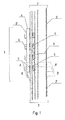
Fig. 1 presents a schematic overview of one embodiment of the guide rail alignment system according to the present disclosure. -
Fig. 2 presents a schematic overview of the embodiment inFig. 1 viewed from the side. -
Fig. 3A presents a schematic overview of the embodiment inFig. 1 as a cross-sectional view along the plane A-A' in preload position before correcting guide rail alignment errors. -
Fig. 3B presents a schematic overview of the embodiment inFig. 1 as a cross-sectional view along the plane B-B' after correcting guide rail alignment errors. -
Fig. 4A presents a pair of guide rail sections joined by a guide rail alignment system according to the present disclosure in preload position before correcting guide rail alignment errors. -
Fig. 4B presents a pair of guide rail sections joined by a guide rail alignment system according to the present disclosure after correcting guide rail alignment errors. -
Fig. 5 presents a schematic overview of an elevator in which a guide rail alignment system according to the present disclosure is used. -
Fig. 1 presents a guiderail alignment system 1 with twoguide rail sections element 4, which in this case is a fishplate. Theguide rail sections Fig. 3 ) and the guide rollers or guide shoes of theelevator car 11 move along the ridge (2', 3') of theguide rail sections fishplate 4 is located on the side of theguide rail sections elevator shaft 10 wall. Theguide rail sections fishplate 4 is approximately as wide as theguide rail sections fishplate 4 varies and can be, for example, 305 mm for the aboveguide rail sections thinnest fishplates 4 can be only 5 mm thick, but a thickness of, for example, 17 mm can be considered typical. Thefishplates 4 can also have additional rigidifying structures, such as ridges in them, which are omitted from the figure. - In this embodiment, the
fishplate 4 is attached to eachguide rail section compression elements 6, which in this case are bolts and theirrespective holes 5', 5 in thefishplate 4 and in theguide rail sections holes 5, 5' in the direction of theguide rail 12, but this does not need to be the only arrangement. A smaller or larger number ofholes 5, 5' and theirrespective bolts 6 is possible, depending on the heaviness of the structure and the forces necessary to correct the alignment errors in theguide rail sections bolts 6 and theirrespective holes 5, 5' do not need to be the same for bothguide rail sections rail alignment system 1. Thebolts 6 can alternatively be screws, adjustable pins, clamps or tighteners, or other compression elements depending on the specific embodiment in question and also the spacing of theholes 5, 5' withcompression elements 6 can vary. - The
guide rail section element 4 do not need to be attached to each other throughcompression elements 6 that needholes 5, 5'. Thecompression elements 6 can be adjustable clamps, presses or other tighteners. When there areholes 5, 5' in theguide rail sections elements 4, theholes 5, 5' do not need to be circular. Further, they can have an opening to the side of theguide rail section element 4 or both, forming a slot rather than a hole with a closed circumference. - It is possible to have more than one connecting
element 4 per guide rail alignment system 1: for example a configuration of two narrow connectingelements 4 with a single row of holes 5' andcompression elements 6 in each can be envisaged. - There are
intermediate elements 7 between theguide rail sections fishplate 4 that in the embodiment ofFig. 1 arecup springs 7 through which thebolts 6 are fitted. InFig. 1 , the guiderail alignment system 1 is depicted in the preload position, i.e. with the cup springs 7 fully compressed by thebolts 6. Thefishplate 4 does not touch theguide rail sections springs 7. In another embodiment, the cup springs or otherintermediate elements 7 could be sunken into the connectingelement 4 so, that in the preload position the connectingelement 4 and theguide rail sections springs 7 in all positions of thebolts 6 and holes 5, 5', this is not necessary, if sufficient adjustment can be achieved with a smaller number ofsprings 7. For example, there could besprings 7 in conjunction only with thebolts 6 on one side of theguide rail junction 8 or only in certain positions on both sides of theguide rail junction 8. Although in this example theintermediate elements 7 are fully compressed, it is possible to compress them only to a predetermined torque, for example 120 Nm by using, for example, a torque wrench. This allows the correction ofguide rail 12 alignment errors by either increasing the bending moment or by decreasing it through tightening thecompression element 6 further or loosening it, respectively. - The
springs 7 have to be compressible enough to allow them to be released, for example, 0.5 mm from the preload position, and to still retain enough mechanical energy to exert a sufficiently large force on theguide rail section guide rail section - The material for the construction of all parts is usually steel, but also other materials might be suitable.
- The guide
rail alignment system 1 of the present disclosure can be used in aguide rail 12 together with guiderail alignment systems 1 known in prior art. When servicing old elevator installations, it might be economical to replace only some of the guiderail alignment systems 1 with ones according to the present disclosure in order to save working time, but allow for the convenient correction ofguide rail 12 alignment errors brought about by the guiderail alignment system 1 presented here. -
Fig. 2 presents the guiderail alignment system 1 ofFig. 1 viewed from one side. Theguide rail sections fishplate 4 and theguide rail sections bolts 6. This is the ideal initial preload position after the installation of theguide rail sections springs 6 were sunken into holes, thefishplate 4 and theguide rail 12 could be pressed against each other throughout the length of thefishplate 4. - It is not always feasible to install the
guide rail sections Fig. 2 . The tensions within theguide rail sections guide rail section guide rail sections rail alignment system 1 in question, or in one or more of the other guiderail alignment systems 1 in theparticular guide rail 12. -
Fig. 3A presents the guiderail alignment system 1 ofFig. 1 as a cross-sectional view along the plane A-A' in preload position before correctingguide rail 12 alignment errors. - In this view, it can be seen that the
guide rail section 3 has a T-shaped cross-sectional profile with a ridge 3'. The surface of theguide rail section 3 that thebolts 6 attach to is slightly sloped relative to the surface facing thefishplate 4. Therefore, there are indentations in theguide rail section 3 around eachhole 5 to provide a horizontal surface for thebolts 6 in the direction of their tightening. In the preload position, the cup springs 7 are fully compressed. However, it would be possible to tighten thesprings 7 to a predetermined torque instead of compressing them fully before correcting theguide rail 12 alignment errors. Thereafter, theguide rail 12 alignment errors could be corrected either by loosening thesprings 7 or tightening them further by a predetermined amount. -
Fig. 3B presents the guiderail alignment system 1 ofFig. 1 as a cross-sectional view along the plane B-B' after correctingguide rail 12 alignment errors. Thebolts 6 have been loosened and, compared toFig. 3A , theguide rail section 3 and thefishplate 4 are further apart. The cup springs 7 are less compressed and exert a bending tension on theguide rail section 3. -
Fig. 4A presents a pair ofguide rail sections rail alignment system 1 in preload position before correctingguide rail 12 alignment errors. Theguide rail sections elevator shaft 10 wall by brackets 14 (not shown). A detail view of the guiderail alignment system 1 is also shown. - In the embodiment of
Fig. 4A , theintermediate elements 7, which in this embodiment are cup springs, are sunken in the connectingelement 4, which in this embodiment is a fishplate, allowing thefishplate 4 and theguide rail sections fishplate 4. All the compression elements, which in this embodiment arebolts 6, are tightened completely, i.e. the complete length of their compression range is used. In cases where the alignment errors would be of different magnitude, direction or position, it is possible that not all thebolts 6 are fully tightened even in the preload position. Theguide rail sections straight guide rail 12 structure (indicated by the dashed line). -
Fig. 4B presents the pair ofguide rail sections rail alignment system 1 ofFig. 4A after correctingguide rail 12 alignment errors. A detail view of the guiderail alignment system 1 is also shown. Thebolts 6 attached to theguide rail section 3 of the guiderail alignment system 1 have been loosened. The partially releasedbolts 6 allow the cup springs 7 to press against theguide rail section 3 creating a bending tension and force between theguide rail sections guide rail sections -
Fig. 5 presents anelevator 9 comprising anelevator shaft 10, anelevator car 11 arranged to move within the elevator shaft 10 (indicated by the doubleheaded arrow), aguide rail 12 and guide shoes orrollers 13 that move along theguide rail 12. Theguide rail 12 comprisesguide rail sections rail alignment systems 1, and is attached to theelevator shaft 10 wall throughbrackets 14. - All support, controlling and safety devices for the
elevator 9 are omitted from the picture for clarity, and any conventional methods can be used for their design. All parts of theelevator 9 are depicted only schematically and their sizes are not drawn proportionally. Although only oneguide rail 12 is shown inFigure 5 , there typically are two of them in eachelevator 9. - Guide
rail alignment systems 1 according to the present disclosure can be used in allguide rail junctions 8 of theelevator 9 or one or more guiderail alignment systems 1 can be according to prior art and used in combination with the guiderail alignment systems 1 disclosed herein.
Claims (14)
- A quide rail alignment system for elevators (1) comprising
at least one connecting element (4),
two guide rail sections (2, 3), each section having two ends, joined to each other from one of their ends by the at least one connecting element (4),
compression elements (6) attaching the at least one connecting element (4) to the guide rail sections (2, 3), and
intermediate elements (7) between the at least one connecting element (4) and at least one of the guide rail sections (2, 3),
characterized in that at least one of the intermediate elements (7) is a spring (7) that is compressible in response to tightening one or more of the compression elements (6). - The guide rail alignment system (1) according to claim 1, characterized in that the at least one connecting element (4) and the two guide rail sections (2, 3) comprise holes (5', 5) that are arranged so, that the holes (5) in the guide rail sections (2, 3) can be aligned with the holes (5') in the connecting element (4) and that the compression elements (6) attach the at least one connecting element (4) to the guide rail sections (2, 3) through the holes (5', 5).
- The guide rail alignment system (1) according to claim 1 or 2, characterized in that the at least one spring (7) is configured to exert pressure on the guide rail section (2, 3) to create a bending tension in it in the direction of the spring force in response to loosening one or more of the compression elements (6).
- The guide rail alignment system (1) according to claim 3, characterized in that the guide rail (12) is configured to be attached to a solid support, wherein the bending tension in the guide rail section (2, 3) caused by the pressure from the partially released at least one spring (7) is configured to alter curvature in the guide rail section (2, 3) and/or to adjust the relative positions of two adjacent guide rail sections (2, 3).
- The guide rail alignment system (1) according to any of the preceding claims, characterized in that curvature of the guide rail section (2, 3) and/or the relative positions of two adjacent guide rail sections (2, 3) is configured to be altered by tightening one or more of the compression elements (6) to a predetermined torque during installation and by thereafter loosening or further tightening one or more of the compression elements (6) by a predetermined amount.
- The guide rail alignment system (1) according to any of the preceding claims, characterized in that the at least one spring (7) is a cup spring, elastic spacer, leaf spring, helical spring or wave spring.
- The guide rail alignment system (1) according to any of the preceding claims, characterized in that the at least one spring (7) is sunken into the connecting element (4) so, that when the compression elements (6) are completely tightened, the connecting element (4) is in contact with the guide rail sections (2, 3) with its whole guide-rail facing surface.
- The guide rail alignment system (1) according to any of the preceding claims, characterized in that the at least one spring (7) is incorporated to the connecting element (4) prior to the assembly of the guide rail alignment system (1).
- The guide rail alignment system (1) according to any of the preceding claims, characterized in that the guide rail alignment system (1) contains one connecting element (4) in which there are at least eight holes (5') arranged in two rows of four in the direction of the guide rail (12).
- A guide rail (12) of an elevator, characterized in that it comprises at least one pair of guide rail sections (2, 3) connected through a guide rail alignment system (1) according to any of claims 1-9.
- An elevator (9) comprising an elevator shaft (10), at least one guide rail (12), an elevator car (11) arranged to move within the elevator shaft (10) along the at least one guide rail (12), characterized in that the elevator (9) comprises at least one guide rail (12) with at least one pair of guide rail sections (2, 3) connected through a guide rail alignment system (1) according to any of claims 1-9.
- A method for correcting elevator guide rail (12)
alignment errors comprising
joining two guide rail sections (2, 3), each section having two ends, to each other from one of their ends by at least one connecting element (4),
attaching the at least one connecting element (4) to the guide rail sections (2, 3) by compression elements (6), characterized in that the method comprises
using spring force between the connecting element (4) and at least one of the guide rail sections (2, 3) to correct guide rail section (2, 3) alignment errors, and
adjusting the spring force by altering the tightness of at least one compression element (6). - The method for correcting guide rail (12) alignment errors according to claim 12, characterized in that the spring force is produced by at least one spring (7), and that the method comprises the steps ofa) during installation or service of the guide rail sections (2, 3), creating a preload on the connecting element (4) and guide rail junctions by tightening at least one of the compression elements (6) to a predetermined torque; andb) after the installation or service is completed, loosening or tightening at least one of the compression elements (6) by a predetermined amount to correct alignment errors in the guide rail (12).
- The method for correcting guide rail (12) alignment errors according to claim 12, characterized in that the spring force is produced by at least one spring (7), and that the method comprises the steps ofa) during installation or service of the guide rail sections (2, 3), creating a preload on the connecting element (4) and guide rail junctions by tightening at least one of the compression elements (6) tightly; andb) after the installation or service is completed, loosening at least one of the compression elements (6) by a predetermined amount to correct alignment errors in the guide rail (12).
Priority Applications (8)
| Application Number | Priority Date | Filing Date | Title |
|---|---|---|---|
| EP13174819.6A EP2821358B1 (en) | 2013-07-03 | 2013-07-03 | Guide rail alignment system for elevators |
| PCT/FI2014/050537 WO2015001183A1 (en) | 2013-07-03 | 2014-06-27 | Guide rail alignment system for elevators |
| SG11201509843XA SG11201509843XA (en) | 2013-07-03 | 2014-06-27 | Guide rail alignment system for elevators |
| AU2014286041A AU2014286041A1 (en) | 2013-07-03 | 2014-06-27 | Guide rail alignment system for elevators |
| JP2016522685A JP6316416B2 (en) | 2013-07-03 | 2014-06-27 | Elevator guide rail positioning system |
| CN201480036346.5A CN105358463B (en) | 2013-07-03 | 2014-06-27 | Guide rail for elevator is to Barebone |
| US14/956,009 US20160083222A1 (en) | 2013-07-03 | 2015-12-01 | Guide rail alignment systems for elevators |
| SA516370343A SA516370343B1 (en) | 2013-07-03 | 2016-01-01 | Guide Rail Alignment System For Elevators |
Applications Claiming Priority (1)
| Application Number | Priority Date | Filing Date | Title |
|---|---|---|---|
| EP13174819.6A EP2821358B1 (en) | 2013-07-03 | 2013-07-03 | Guide rail alignment system for elevators |
Publications (2)
| Publication Number | Publication Date |
|---|---|
| EP2821358A1 EP2821358A1 (en) | 2015-01-07 |
| EP2821358B1 true EP2821358B1 (en) | 2016-11-30 |
Family
ID=48745780
Family Applications (1)
| Application Number | Title | Priority Date | Filing Date |
|---|---|---|---|
| EP13174819.6A Active EP2821358B1 (en) | 2013-07-03 | 2013-07-03 | Guide rail alignment system for elevators |
Country Status (8)
| Country | Link |
|---|---|
| US (1) | US20160083222A1 (en) |
| EP (1) | EP2821358B1 (en) |
| JP (1) | JP6316416B2 (en) |
| CN (1) | CN105358463B (en) |
| AU (1) | AU2014286041A1 (en) |
| SA (1) | SA516370343B1 (en) |
| SG (1) | SG11201509843XA (en) |
| WO (1) | WO2015001183A1 (en) |
Families Citing this family (12)
| Publication number | Priority date | Publication date | Assignee | Title |
|---|---|---|---|---|
| DE102015206345A1 (en) * | 2015-04-09 | 2016-10-13 | Thyssenkrupp Ag | Guide rail for an elevator system |
| EP3280673B1 (en) | 2015-04-10 | 2019-06-05 | Otis Elevator Company | Elevator safety gear alignment system and method |
| ES2665562B1 (en) * | 2016-10-25 | 2019-02-05 | S A De Vera Savera | Union system with self-aligned, for elevator guides |
| CA3041820A1 (en) | 2016-11-24 | 2018-05-31 | Inventio Ag | Method for mounting and alignment device for aligning a guide rail of an elevator system |
| EP3336040B1 (en) * | 2016-12-19 | 2021-03-17 | KONE Corporation | Arrangement and method for aligning guide rails of an elevator |
| EP3339230A1 (en) * | 2016-12-20 | 2018-06-27 | Otis Elevator Company | Foldable guide rail tracks for elevator systems |
| CN108910656B (en) * | 2018-07-27 | 2019-05-21 | 煤炭工业合肥设计研究院有限责任公司 | A kind of cage guide attachment device and attaching method thereof |
| CN111056402A (en) * | 2018-10-17 | 2020-04-24 | 广州广日电梯工业有限公司 | Adjusting device and adjusting method for elevator guide rail |
| WO2020193186A2 (en) * | 2019-03-26 | 2020-10-01 | Inventio Ag | Aligning device and method for aligning a guide rail of an elevator system |
| EP3766817B1 (en) * | 2019-07-16 | 2023-06-21 | KONE Corporation | Elevator guide rail |
| CN113772513B (en) * | 2021-10-15 | 2023-04-07 | 广州塞维拉电梯轨道系统有限公司 | Elevator guide rail detection method and system |
| CN115962704B (en) * | 2023-03-16 | 2023-05-19 | 蒂升电梯(中国)有限公司成都分公司 | Device for efficiently measuring straightness of elevator guide rail and measuring method thereof |
Family Cites Families (26)
| Publication number | Priority date | Publication date | Assignee | Title |
|---|---|---|---|---|
| US1720202A (en) * | 1928-06-06 | 1929-07-09 | Union Drawn Steel Company | Guide rail |
| US1836713A (en) * | 1930-03-26 | 1931-12-15 | William B Hewitt | Tie plate |
| US2848077A (en) * | 1956-01-24 | 1958-08-19 | Otis Elevator Co | Elevator guide rail fastener |
| US3199642A (en) * | 1964-02-21 | 1965-08-10 | Otis Elevator Co | Rail positioning and fastening device |
| US3420337A (en) * | 1967-09-21 | 1969-01-07 | John E Magee | Rail fastener |
| US4079817A (en) | 1976-11-16 | 1978-03-21 | Westinghouse Electric Corporation | Elevator system with fish plate for correcting an out-of-tolerance between guide dimension |
| US4431087A (en) * | 1981-05-29 | 1984-02-14 | Westinghouse Electric Corp. | Guide rail clamping method and assembly |
| US4577729A (en) * | 1984-12-05 | 1986-03-25 | Westinghouse Electric Corp. | Guide rail clamping assembly |
| CH680786A5 (en) * | 1990-03-26 | 1992-11-13 | Inventio Ag | |
| US5020641A (en) * | 1990-06-20 | 1991-06-04 | Otis Elevator Company | Method and apparatus for erecting hydraulic elevator rails |
| FI88282C (en) * | 1990-11-28 | 1993-04-26 | Kone Oy | Equipment for checking the straightness of lift guides |
| DE4220799A1 (en) * | 1992-02-28 | 1993-09-02 | Hilti Ag | DEVICE FOR STORING RAILS |
| FI92314C (en) * | 1992-07-23 | 1994-10-25 | Kone Oy | Arrangement for attaching an elevator cable to a cable tray |
| JP3396534B2 (en) * | 1994-04-26 | 2003-04-14 | 株式会社東芝 | Elevator guide rail fixing device |
| JPH0952675A (en) * | 1995-08-15 | 1997-02-25 | Toshiba Fa Syst Eng Kk | Elevator guide rail mounting device |
| JP3488550B2 (en) * | 1995-09-20 | 2004-01-19 | 東芝エレベータ株式会社 | Elevator guide rail connection device |
| JPH1087224A (en) * | 1996-09-11 | 1998-04-07 | Hitachi Ltd | Guide rail for elevator |
| ATE245595T1 (en) * | 1999-12-23 | 2003-08-15 | De Vera Savera Sa | INSTALLATION SYSTEM FOR A GUIDE DEVICE OF AN ELEVATOR CABIN |
| JP4756771B2 (en) * | 2001-05-17 | 2011-08-24 | 三菱電機株式会社 | Elevator guide rail device |
| JP2004536002A (en) * | 2001-07-30 | 2004-12-02 | インベンテイオ・アクテイエンゲゼルシヤフト | Method and apparatus for mounting guide rails |
| JP2003266261A (en) * | 2002-03-12 | 2003-09-24 | Toshiba Elevator Co Ltd | Guide rail processing method |
| ES2333649T3 (en) * | 2003-07-15 | 2010-02-25 | Monteferro S.P.A. | POSITIONING DEVICE FOR ELEVATOR GUIDES. |
| JP2005132597A (en) * | 2003-10-31 | 2005-05-26 | Mitsubishi Electric Corp | Guide rail fixing device for elevator |
| EP1866481B1 (en) * | 2005-04-02 | 2010-05-19 | Kölner Verkehrs-Betriebe AG | Rail bearing |
| FI119983B (en) * | 2006-05-24 | 2009-05-29 | Kone Corp | Procedure and system for mounting guides to a lift |
| FI20100129A (en) * | 2010-03-24 | 2011-09-25 | Kone Corp | Guide rail for elevator and elevator |
-
2013
- 2013-07-03 EP EP13174819.6A patent/EP2821358B1/en active Active
-
2014
- 2014-06-27 JP JP2016522685A patent/JP6316416B2/en not_active Expired - Fee Related
- 2014-06-27 CN CN201480036346.5A patent/CN105358463B/en active Active
- 2014-06-27 SG SG11201509843XA patent/SG11201509843XA/en unknown
- 2014-06-27 AU AU2014286041A patent/AU2014286041A1/en not_active Abandoned
- 2014-06-27 WO PCT/FI2014/050537 patent/WO2015001183A1/en active Application Filing
-
2015
- 2015-12-01 US US14/956,009 patent/US20160083222A1/en not_active Abandoned
-
2016
- 2016-01-01 SA SA516370343A patent/SA516370343B1/en unknown
Non-Patent Citations (1)
| Title |
|---|
| None * |
Also Published As
| Publication number | Publication date |
|---|---|
| SA516370343B1 (en) | 2020-03-22 |
| CN105358463B (en) | 2018-01-30 |
| CN105358463A (en) | 2016-02-24 |
| JP2016523217A (en) | 2016-08-08 |
| US20160083222A1 (en) | 2016-03-24 |
| SG11201509843XA (en) | 2016-01-28 |
| JP6316416B2 (en) | 2018-04-25 |
| EP2821358A1 (en) | 2015-01-07 |
| WO2015001183A1 (en) | 2015-01-08 |
| AU2014286041A1 (en) | 2016-02-18 |
Similar Documents
| Publication | Publication Date | Title |
|---|---|---|
| EP2821358B1 (en) | Guide rail alignment system for elevators | |
| US9797426B2 (en) | Profile bar, profile assembly and method for producing a profile assembly | |
| KR101200589B1 (en) | Manufacturing method of prestressed steel beam using tightening forces of bolts | |
| US20180362299A1 (en) | Fastening devices for fastening elevator rails | |
| WO2010122992A1 (en) | Composite steel sheet pile and steel sheet pile wall using the composite steel sheet pile | |
| CN103189676B (en) | Ductwork | |
| CN113544072B (en) | Alignment device and method for aligning guide rails of an elevator installation | |
| US20170014888A1 (en) | Tool slide | |
| JP2007523022A (en) | Elevator rail support bracket | |
| JP6593952B2 (en) | How to install the seismic isolation device | |
| US11198326B2 (en) | Axle system | |
| CN109235244B (en) | Adjusting device for bridge support | |
| JP2660828B2 (en) | Elastic bearing device for cross girder bearing and method of installing the same | |
| EP2174902A1 (en) | Elevator guide rail fixing brackets | |
| US6537155B2 (en) | Counterweight arbor guide system | |
| CN109781503B (en) | Test piece boundary constraint applying device in lateral impact resistance experiment | |
| JP6474575B2 (en) | Brace seismic reinforcement structure and seismic reinforcement method for existing buildings | |
| JP4705004B2 (en) | Strain adjustment jig and strain adjustment method | |
| CN109629395B (en) | Limiting V-shaped clamping plate for positioning concrete stay cable guide pipe and use method | |
| CN110485561A (en) | A kind of bolt connection node and its construction method of adjustable prefabricated components length | |
| JP7083284B2 (en) | Intermediate clamp | |
| JP2001027282A (en) | Base isolating member position adjusting method and device | |
| CN211549333U (en) | Aluminum alloy window with high frame stability | |
| CN1833078A (en) | Strap tightening device | |
| JPH08189189A (en) | Jig for correcting upper part of form |
Legal Events
| Date | Code | Title | Description |
|---|---|---|---|
| PUAI | Public reference made under article 153(3) epc to a published international application that has entered the european phase |
Free format text: ORIGINAL CODE: 0009012 |
|
| 17P | Request for examination filed |
Effective date: 20130703 |
|
| AK | Designated contracting states |
Kind code of ref document: A1 Designated state(s): AL AT BE BG CH CY CZ DE DK EE ES FI FR GB GR HR HU IE IS IT LI LT LU LV MC MK MT NL NO PL PT RO RS SE SI SK SM TR |
|
| AX | Request for extension of the european patent |
Extension state: BA ME |
|
| R17P | Request for examination filed (corrected) |
Effective date: 20150706 |
|
| RBV | Designated contracting states (corrected) |
Designated state(s): AL AT BE BG CH CY CZ DE DK EE ES FI FR GB GR HR HU IE IS IT LI LT LU LV MC MK MT NL NO PL PT RO RS SE SI SK SM TR |
|
| GRAP | Despatch of communication of intention to grant a patent |
Free format text: ORIGINAL CODE: EPIDOSNIGR1 |
|
| INTG | Intention to grant announced |
Effective date: 20160222 |
|
| GRAP | Despatch of communication of intention to grant a patent |
Free format text: ORIGINAL CODE: EPIDOSNIGR1 |
|
| INTG | Intention to grant announced |
Effective date: 20160706 |
|
| GRAS | Grant fee paid |
Free format text: ORIGINAL CODE: EPIDOSNIGR3 |
|
| GRAA | (expected) grant |
Free format text: ORIGINAL CODE: 0009210 |
|
| AK | Designated contracting states |
Kind code of ref document: B1 Designated state(s): AL AT BE BG CH CY CZ DE DK EE ES FI FR GB GR HR HU IE IS IT LI LT LU LV MC MK MT NL NO PL PT RO RS SE SI SK SM TR |
|
| REG | Reference to a national code |
Ref country code: CH Ref legal event code: EP Ref country code: GB Ref legal event code: FG4D |
|
| REG | Reference to a national code |
Ref country code: AT Ref legal event code: REF Ref document number: 849588 Country of ref document: AT Kind code of ref document: T Effective date: 20161215 |
|
| REG | Reference to a national code |
Ref country code: IE Ref legal event code: FG4D |
|
| REG | Reference to a national code |
Ref country code: DE Ref legal event code: R096 Ref document number: 602013014627 Country of ref document: DE |
|
| PG25 | Lapsed in a contracting state [announced via postgrant information from national office to epo] |
Ref country code: LV Free format text: LAPSE BECAUSE OF FAILURE TO SUBMIT A TRANSLATION OF THE DESCRIPTION OR TO PAY THE FEE WITHIN THE PRESCRIBED TIME-LIMIT Effective date: 20161130 |
|
| REG | Reference to a national code |
Ref country code: LT Ref legal event code: MG4D |
|
| REG | Reference to a national code |
Ref country code: NL Ref legal event code: MP Effective date: 20161130 |
|
| REG | Reference to a national code |
Ref country code: AT Ref legal event code: MK05 Ref document number: 849588 Country of ref document: AT Kind code of ref document: T Effective date: 20161130 |
|
| PG25 | Lapsed in a contracting state [announced via postgrant information from national office to epo] |
Ref country code: SE Free format text: LAPSE BECAUSE OF FAILURE TO SUBMIT A TRANSLATION OF THE DESCRIPTION OR TO PAY THE FEE WITHIN THE PRESCRIBED TIME-LIMIT Effective date: 20161130 Ref country code: GR Free format text: LAPSE BECAUSE OF FAILURE TO SUBMIT A TRANSLATION OF THE DESCRIPTION OR TO PAY THE FEE WITHIN THE PRESCRIBED TIME-LIMIT Effective date: 20170301 Ref country code: NO Free format text: LAPSE BECAUSE OF FAILURE TO SUBMIT A TRANSLATION OF THE DESCRIPTION OR TO PAY THE FEE WITHIN THE PRESCRIBED TIME-LIMIT Effective date: 20170228 Ref country code: LT Free format text: LAPSE BECAUSE OF FAILURE TO SUBMIT A TRANSLATION OF THE DESCRIPTION OR TO PAY THE FEE WITHIN THE PRESCRIBED TIME-LIMIT Effective date: 20161130 |
|
| PG25 | Lapsed in a contracting state [announced via postgrant information from national office to epo] |
Ref country code: HR Free format text: LAPSE BECAUSE OF FAILURE TO SUBMIT A TRANSLATION OF THE DESCRIPTION OR TO PAY THE FEE WITHIN THE PRESCRIBED TIME-LIMIT Effective date: 20161130 Ref country code: RS Free format text: LAPSE BECAUSE OF FAILURE TO SUBMIT A TRANSLATION OF THE DESCRIPTION OR TO PAY THE FEE WITHIN THE PRESCRIBED TIME-LIMIT Effective date: 20161130 Ref country code: AT Free format text: LAPSE BECAUSE OF FAILURE TO SUBMIT A TRANSLATION OF THE DESCRIPTION OR TO PAY THE FEE WITHIN THE PRESCRIBED TIME-LIMIT Effective date: 20161130 Ref country code: PL Free format text: LAPSE BECAUSE OF FAILURE TO SUBMIT A TRANSLATION OF THE DESCRIPTION OR TO PAY THE FEE WITHIN THE PRESCRIBED TIME-LIMIT Effective date: 20161130 Ref country code: FI Free format text: LAPSE BECAUSE OF FAILURE TO SUBMIT A TRANSLATION OF THE DESCRIPTION OR TO PAY THE FEE WITHIN THE PRESCRIBED TIME-LIMIT Effective date: 20161130 Ref country code: ES Free format text: LAPSE BECAUSE OF FAILURE TO SUBMIT A TRANSLATION OF THE DESCRIPTION OR TO PAY THE FEE WITHIN THE PRESCRIBED TIME-LIMIT Effective date: 20161130 Ref country code: PT Free format text: LAPSE BECAUSE OF FAILURE TO SUBMIT A TRANSLATION OF THE DESCRIPTION OR TO PAY THE FEE WITHIN THE PRESCRIBED TIME-LIMIT Effective date: 20170330 |
|
| PG25 | Lapsed in a contracting state [announced via postgrant information from national office to epo] |
Ref country code: NL Free format text: LAPSE BECAUSE OF FAILURE TO SUBMIT A TRANSLATION OF THE DESCRIPTION OR TO PAY THE FEE WITHIN THE PRESCRIBED TIME-LIMIT Effective date: 20161130 |
|
| REG | Reference to a national code |
Ref country code: FR Ref legal event code: PLFP Year of fee payment: 5 |
|
| PG25 | Lapsed in a contracting state [announced via postgrant information from national office to epo] |
Ref country code: CZ Free format text: LAPSE BECAUSE OF FAILURE TO SUBMIT A TRANSLATION OF THE DESCRIPTION OR TO PAY THE FEE WITHIN THE PRESCRIBED TIME-LIMIT Effective date: 20161130 Ref country code: SK Free format text: LAPSE BECAUSE OF FAILURE TO SUBMIT A TRANSLATION OF THE DESCRIPTION OR TO PAY THE FEE WITHIN THE PRESCRIBED TIME-LIMIT Effective date: 20161130 Ref country code: RO Free format text: LAPSE BECAUSE OF FAILURE TO SUBMIT A TRANSLATION OF THE DESCRIPTION OR TO PAY THE FEE WITHIN THE PRESCRIBED TIME-LIMIT Effective date: 20161130 Ref country code: EE Free format text: LAPSE BECAUSE OF FAILURE TO SUBMIT A TRANSLATION OF THE DESCRIPTION OR TO PAY THE FEE WITHIN THE PRESCRIBED TIME-LIMIT Effective date: 20161130 Ref country code: DK Free format text: LAPSE BECAUSE OF FAILURE TO SUBMIT A TRANSLATION OF THE DESCRIPTION OR TO PAY THE FEE WITHIN THE PRESCRIBED TIME-LIMIT Effective date: 20161130 |
|
| PG25 | Lapsed in a contracting state [announced via postgrant information from national office to epo] |
Ref country code: IT Free format text: LAPSE BECAUSE OF FAILURE TO SUBMIT A TRANSLATION OF THE DESCRIPTION OR TO PAY THE FEE WITHIN THE PRESCRIBED TIME-LIMIT Effective date: 20161130 Ref country code: BG Free format text: LAPSE BECAUSE OF FAILURE TO SUBMIT A TRANSLATION OF THE DESCRIPTION OR TO PAY THE FEE WITHIN THE PRESCRIBED TIME-LIMIT Effective date: 20170228 Ref country code: SM Free format text: LAPSE BECAUSE OF FAILURE TO SUBMIT A TRANSLATION OF THE DESCRIPTION OR TO PAY THE FEE WITHIN THE PRESCRIBED TIME-LIMIT Effective date: 20161130 Ref country code: BE Free format text: LAPSE BECAUSE OF FAILURE TO SUBMIT A TRANSLATION OF THE DESCRIPTION OR TO PAY THE FEE WITHIN THE PRESCRIBED TIME-LIMIT Effective date: 20161130 |
|
| REG | Reference to a national code |
Ref country code: DE Ref legal event code: R097 Ref document number: 602013014627 Country of ref document: DE |
|
| PLBE | No opposition filed within time limit |
Free format text: ORIGINAL CODE: 0009261 |
|
| STAA | Information on the status of an ep patent application or granted ep patent |
Free format text: STATUS: NO OPPOSITION FILED WITHIN TIME LIMIT |
|
| 26N | No opposition filed |
Effective date: 20170831 |
|
| PG25 | Lapsed in a contracting state [announced via postgrant information from national office to epo] |
Ref country code: SI Free format text: LAPSE BECAUSE OF FAILURE TO SUBMIT A TRANSLATION OF THE DESCRIPTION OR TO PAY THE FEE WITHIN THE PRESCRIBED TIME-LIMIT Effective date: 20161130 |
|
| REG | Reference to a national code |
Ref country code: CH Ref legal event code: PL |
|
| REG | Reference to a national code |
Ref country code: IE Ref legal event code: MM4A |
|
| PG25 | Lapsed in a contracting state [announced via postgrant information from national office to epo] |
Ref country code: LI Free format text: LAPSE BECAUSE OF NON-PAYMENT OF DUE FEES Effective date: 20170731 Ref country code: CH Free format text: LAPSE BECAUSE OF NON-PAYMENT OF DUE FEES Effective date: 20170731 Ref country code: IE Free format text: LAPSE BECAUSE OF NON-PAYMENT OF DUE FEES Effective date: 20170703 |
|
| PG25 | Lapsed in a contracting state [announced via postgrant information from national office to epo] |
Ref country code: LU Free format text: LAPSE BECAUSE OF NON-PAYMENT OF DUE FEES Effective date: 20170703 |
|
| REG | Reference to a national code |
Ref country code: FR Ref legal event code: PLFP Year of fee payment: 6 |
|
| PG25 | Lapsed in a contracting state [announced via postgrant information from national office to epo] |
Ref country code: MT Free format text: LAPSE BECAUSE OF NON-PAYMENT OF DUE FEES Effective date: 20170703 |
|
| PG25 | Lapsed in a contracting state [announced via postgrant information from national office to epo] |
Ref country code: MC Free format text: LAPSE BECAUSE OF FAILURE TO SUBMIT A TRANSLATION OF THE DESCRIPTION OR TO PAY THE FEE WITHIN THE PRESCRIBED TIME-LIMIT Effective date: 20161130 Ref country code: HU Free format text: LAPSE BECAUSE OF FAILURE TO SUBMIT A TRANSLATION OF THE DESCRIPTION OR TO PAY THE FEE WITHIN THE PRESCRIBED TIME-LIMIT; INVALID AB INITIO Effective date: 20130703 |
|
| PG25 | Lapsed in a contracting state [announced via postgrant information from national office to epo] |
Ref country code: CY Free format text: LAPSE BECAUSE OF FAILURE TO SUBMIT A TRANSLATION OF THE DESCRIPTION OR TO PAY THE FEE WITHIN THE PRESCRIBED TIME-LIMIT Effective date: 20161130 |
|
| PG25 | Lapsed in a contracting state [announced via postgrant information from national office to epo] |
Ref country code: MK Free format text: LAPSE BECAUSE OF FAILURE TO SUBMIT A TRANSLATION OF THE DESCRIPTION OR TO PAY THE FEE WITHIN THE PRESCRIBED TIME-LIMIT Effective date: 20161130 |
|
| PG25 | Lapsed in a contracting state [announced via postgrant information from national office to epo] |
Ref country code: TR Free format text: LAPSE BECAUSE OF FAILURE TO SUBMIT A TRANSLATION OF THE DESCRIPTION OR TO PAY THE FEE WITHIN THE PRESCRIBED TIME-LIMIT Effective date: 20161130 |
|
| PG25 | Lapsed in a contracting state [announced via postgrant information from national office to epo] |
Ref country code: AL Free format text: LAPSE BECAUSE OF FAILURE TO SUBMIT A TRANSLATION OF THE DESCRIPTION OR TO PAY THE FEE WITHIN THE PRESCRIBED TIME-LIMIT Effective date: 20161130 Ref country code: IS Free format text: LAPSE BECAUSE OF FAILURE TO SUBMIT A TRANSLATION OF THE DESCRIPTION OR TO PAY THE FEE WITHIN THE PRESCRIBED TIME-LIMIT Effective date: 20170330 |
|
| PGFP | Annual fee paid to national office [announced via postgrant information from national office to epo] |
Ref country code: GB Payment date: 20220720 Year of fee payment: 10 Ref country code: DE Payment date: 20220720 Year of fee payment: 10 |
|
| PGFP | Annual fee paid to national office [announced via postgrant information from national office to epo] |
Ref country code: FR Payment date: 20220720 Year of fee payment: 10 |
|
| REG | Reference to a national code |
Ref country code: DE Ref legal event code: R119 Ref document number: 602013014627 Country of ref document: DE |
|
| GBPC | Gb: european patent ceased through non-payment of renewal fee |
Effective date: 20230703 |