EP2820331B1 - Schrauben-muttern-anordnung mit wälzkörpern - Google Patents
Schrauben-muttern-anordnung mit wälzkörpern Download PDFInfo
- Publication number
- EP2820331B1 EP2820331B1 EP13713999.4A EP13713999A EP2820331B1 EP 2820331 B1 EP2820331 B1 EP 2820331B1 EP 13713999 A EP13713999 A EP 13713999A EP 2820331 B1 EP2820331 B1 EP 2820331B1
- Authority
- EP
- European Patent Office
- Prior art keywords
- screw
- coupling
- nut
- helix
- coupling element
- Prior art date
- Legal status (The legal status is an assumption and is not a legal conclusion. Google has not performed a legal analysis and makes no representation as to the accuracy of the status listed.)
- Not-in-force
Links
- 238000005096 rolling process Methods 0.000 title description 4
- 230000008878 coupling Effects 0.000 claims description 109
- 238000010168 coupling process Methods 0.000 claims description 109
- 238000005859 coupling reaction Methods 0.000 claims description 109
- 238000010276 construction Methods 0.000 description 10
- 238000004804 winding Methods 0.000 description 4
- 238000000034 method Methods 0.000 description 2
- 238000006073 displacement reaction Methods 0.000 description 1
- 238000012423 maintenance Methods 0.000 description 1
- 238000004519 manufacturing process Methods 0.000 description 1
- 239000007787 solid Substances 0.000 description 1
Images

Classifications
-
- F—MECHANICAL ENGINEERING; LIGHTING; HEATING; WEAPONS; BLASTING
- F16—ENGINEERING ELEMENTS AND UNITS; GENERAL MEASURES FOR PRODUCING AND MAINTAINING EFFECTIVE FUNCTIONING OF MACHINES OR INSTALLATIONS; THERMAL INSULATION IN GENERAL
- F16H—GEARING
- F16H25/00—Gearings comprising primarily only cams, cam-followers and screw-and-nut mechanisms
- F16H25/18—Gearings comprising primarily only cams, cam-followers and screw-and-nut mechanisms for conveying or interconverting oscillating or reciprocating motions
- F16H25/20—Screw mechanisms
- F16H25/22—Screw mechanisms with balls, rollers, or similar members between the co-operating parts; Elements essential to the use of such members
- F16H25/2247—Screw mechanisms with balls, rollers, or similar members between the co-operating parts; Elements essential to the use of such members with rollers
- F16H25/2261—Screw mechanisms with balls, rollers, or similar members between the co-operating parts; Elements essential to the use of such members with rollers arranged substantially perpendicular to the screw shaft axis
Definitions
- the present invention refers in general to a screw - nut screw coupling. More particularly, it refers to a screw - nut screw coupling that improves the performance through its particular configuration.
- the screw - nut screw couplings of the prior art commonly referred to as re-circulating ball screws, consist of a threaded shaft surrounded by a nut with integrated balls and a re-circulating ball mechanism.
- the re-circulating ball screws are the most commonly used types of control for industrial machines and precision instruments.
- a re-circulating ball screw allows to transform a rotary motion into a linear motion and vice versa, in applications requiring high precision levels, motion reversibility and efficiency.
- the re-circulating ball screws operate with rolling friction as a result of the presence of balls, each ball being free to rotate about an axis parallel to the screw and each ball being interposed between screw and nut screw.
- re-circulating ball systems are carried out to obtain a rolling path that deviates, at least for a portion, from the grooves formed on the screw and nut screw.
- re-circulating ball screws are known. Said screws are obtained with particular constructions of the nut surrounding the screw.
- the recirculation may be obtained through one or more circuits with an external recirculation tube or one or more circuits with internal deflector.
- the typology adopted to obtain the recirculation of the balls affects the maximum speed of rotation of the screw or nut screw, the load capacity of the system and the rigidity of the nut screw.
- the re-circulating ball screws are not adapted to support an axial load, for instance in case of a screw which rotates about an axis of rotation which is not perfectly horizontal to the ground.
- FIG. 1 Another known typology of screw - nut screw coupling is commonly referred to as planetary roller screw in which the coupling elements between screw and nut screw are threaded rollers interposed between screw and nut screw.
- the features of the coupling depend on the typology of thread formed on the rollers and consequently on the screw.
- the planetary rollers rotate about an axis of rotation parallel to the axis of rotation of the screw and their construction is complex.
- An aim of the invention is to obviate the above mentioned drawbacks and further ones through a screw - nut screw coupling whose use is more flexible as this coupling may support also axial loads.
- Another aim of the invention is to carry out a screw - nut screw coupling offering a good performance on avoiding the presence of a recirculation of balls or planetary rollers.
- a screw - nut screw coupling adapted to couple a screw with a nut screw, said screw being adapted to be rotated about a first axis of rotation oriented in a first direction, and said nut screw being arranged to surround, at least partially, the screw.
- the screw - nut screw coupling comprises one or more coupling elements and which, couple the screw to the nut screw and the one or more coupling elements rotate about a second axis of rotation, oriented in a second direction which is different from the first direction.
- the screw - nut screw coupling is characterized by comprising a first helix and a second helix, of which the first helix has the same pitch as the second helix and a shorter radius than the second helix, and the one or more coupling elements may be pivoted at a first end to the first helix and at a second end to the second helix.
- the presence of the first helix and second helix allows to pivot the coupling elements to elements that may be carried out regardless of the screw or nut screw and in some cases, it is possible to obtain a more solid and stable connection for the coupling elements.
- the coupling element may rest and/or roll on surfaces different from those on which a ball in a re-circulating ball coupling or in a planetary roller coupling rests and/or rolls so that it is possible to obtain coupling elements which may support loads oriented in directions different from the radial directions to the screw, for instance loads oriented in axial directions to the screw.
- said second axis of rotation is substantially perpendicular to the first axis of rotation about which the screw rotates.
- the axis of rotation substantially perpendicular to the axis of rotation about which the screw rotates, allows to obtain coupling elements which are able to best support loads oriented in directions substantially axial to the screw.
- said second axis of rotation may be integral with the screw or alternatively, said second axis of rotation may be integral with the nut screw.
- the so-described construction allows to make the axis of rotation of the coupling element integral with the screw or with the nut screw, which allows to select the most comfortable construction or the construction that meets certain criteria for the planning of the screw - nut screw coupling.
- the one or more coupling elements may be pivoted to the nut screw and the screw may comprise guiding means on which the one or more coupling elements roll or alternatively in which the one or more coupling elements may be pivoted to the screw and the nut screw may comprise guiding means on which the one or more coupling elements roll.
- the one or more coupling elements are pivoted to the screw or nut screw and are not free to move in respect to the screw or nut screw so as to avoid the presence of a recirculation or planetary rollers.
- the first helix may be bound to the screw or alternatively, the second helix may be bound to the nut screw.
- a substantially cylindrical shaft is usable and the first helix may be bound to the outer surface of said shaft on simplifying the construction of the screw.
- binding the second helix to the nut screw it is possible to use a nut screw without internal thread, the second helix being bound to the internal walls.
- a first coupling element is pivoted by means of a first pin and a second coupling element is pivoted by means of a second pin.
- a thread having a rectangular profile is obtained on the nut screw, into which thread the screw can be screwed, a first groove is obtained on a first side of the thread of the nut screw and the first coupling element rolls on said first groove, and a second groove is obtained on a second side of the thread of the nut screw and the second coupling element rolls on said second groove, respectively while in case a thread having a rectangular profile is obtained on the screw, a first groove is obtained on a first side of the thread of the screw and the first coupling element rolls on said first groove, and a second groove is obtained on a second side of the thread of the screw and the second coupling element rolls on said second groove, respectively.
- said coupling element has an oblong shape in the direction of its axis of rotation.
- said coupling element may be shaped like an ellipsoid.
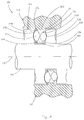
- number 10 denotes a screw - nut screw coupling on the whole.
- the screw - nut screw coupling 10 comprises a first nut screw 12 which surrounds a first screw 14 partially.
- the first screw 14 comprises a shaft 16 to which a first narrow helix 18 is constrained by means of a key.
- different fixing methods equivalent to the key 22 may be utilized.
- a first coupling element 24 showing an ellipsoidal shape is pivoted to the first narrow helix 18 by means of a first pin 26.
- the first pin 26 passes through the first coupling element 24 and is pivoted on a first large helix 20.
- the first narrow helix 18 surrounds the shaft 16 and forms a spiral having a certain pitch and is at a constant distance from the axis of rotation 15 of the shaft 16.
- the first large helix 20 forms a spiral having the same pitch as the first narrow helix 18 but it is at a greater distance from the axis of rotation 15 than the first narrow helix 18.
- Figure 1 shows only a portion of the first narrow helix 18 and a portion of the second large helix 20 which portions correspond to a winding but it is to be intended that on applying a screw - nut screw coupling according to the invention, the shaft 16 may be wrapped by a high number of windings.
- a thread with a rectangular cross-section is obtained on the first nut screw 12.
- the first screw 14 may be screwed into said thread.
- a first groove 30 is obtained on a first side 28 of the thread of the first nut screw 12 and is shaped like an arc of a circle.
- the first coupling element 24 is in contact in at least one point of the first groove 30 so as to rotate about the first pin 26 on maintaining the first narrow helix 18 and the first large helix 20 spaced from the first side 28.
- a second coupling element 32 is hinged to the first narrow helix 18 and to the first large helix 20 by means of a second pin 34.
- the second coupling element 32 rolls on a second groove 38 obtained on a second side 36 of the thread of the nut screw 12.
- the second coupling element 32 keeps the first narrow helix 18 and the first large helix 20 spaced from the second side 36.
- the first coupling element 24 and the second coupling element 32 are spaced from each other so that it is not possible for them to come into contact with each other.
- the first pin 26 and second pin 34 are pivoted at a predetermined distance along the main direction of the axis of rotation 15 of the shaft 16.
- Each respective axis of rotation of the first coupling element 24 and second coupling element 32 intersects the axis of rotation 15 and has a radial development from said axis of rotation.
- a series of coupling elements corresponding to the first and second coupling element 24 and 32 are pivoted to the first narrow helix 18 and first large helix 20 so as to rotate on the first groove 30 and second groove 38 alternately.
- the first nut screw 12 may be obtained, for instance, on a flange nut adapted to be bound to a carriage of a machine tool, and the first screw 14 may be coupled, for instance, to a motor which rotates said screw so that a rotation of the screw 14 involves a translation of the nut and a consequent displacement of the carriage.
- a screw - nut screw coupling 110 comprises a nut screw 112 surrounding a screw 114 partially.
- the screw 114 comprises a shaft 116 on which a thread showing a rectangular profile is obtained.
- a large helix 120 is bound to the nut screw 112 so as to form a single body.
- different fixing methods may be utilized, which are to be considered as equivalent to the one-body binding.
- a first ellipsoid-shaped coupling element 124 is pivoted to the large helix 120 by means of a third pin 126.
- the first pin 126 passes through the first coupling element 124 on pivoting thus on a narrow helix 118.
- the narrow helix 118 surrounds the shaft 116 at a distance without contact on forming a helix having a predetermined pitch and is at a constant distance from the axis of rotation 115 of the shaft 116.
- the large helix 120 forms a helix having the same pitch as the second narrow helix 18 but at a greater distance from the axis of rotation 15 than the second narrow helix.
- Figure 2 shows only a portion of the narrow helix 118 and a portion of the large helix 120 which portions correspond to a winding but it is to be intended that in the application of a screw - nut screw coupling according to the invention, the shaft 116 may be wrapped by a greater number of windings.
- a first groove 130 shaped like an arc of a circle is obtained on a first side 128 of the thread of the screw 114.
- the first coupling element 124 is in contact in at least one point of the third groove 130 so as to rotate about the first pin 126 on keeping the narrow helix 118 and the large helix 120 spaced from the first side.
- a second coupling element 132 is pivoted to the narrow helix 118 and large helix 120 by means of a second pin 34.
- the second coupling element 132 rolls on a second groove 138 obtained on a second side 136 of the thread of the screw 114.
- the second coupling element 132 keeps the narrow helix 118 and the large helix 120 spaced from the second side 136.
- the first coupling element 124 and the second coupling element 132 are spaced from each other so that they do not come into contact with each other.
- the first pin 126 and the second pin 134 are pivoted at a predetermined distance along the main direction of the axis of rotation 115 of the shaft 116.
- Each respective axis of rotation of the first coupling element 124 and second coupling element 132 intersects the axis of rotation 115 and has a radial development from said axis of rotation.
- the nut screw 112 may be obtained, for instance, also on a flange nut adapted to be constrained to a carriage of a machine tool, and the screw 114 may be coupled, for instance, to a motor which rotates said screw.
- a screw - nut screw coupling may be provided with a removable narrow or large helix so that said helix may be removed and it is possible to have access to the coupling elements to replace them or to attend to a general maintenance.
- screw - nut screw coupling according to the invention may be used also in case of axial load or mixed load so that a higher flexibility of utilization is obtained.
- a technician of the sector can make further changes or variants which are to be considered as included in the scope of protection of the present invention.
- grooves and profiles showing shapes different from a thread with a rectangular profile may be obtained on the screw and/or nut screw, or the coupling elements may have shapes different from the ellipsoid shape such as a spherical shape or a cylindrical shape.
- one or more coupling elements may be pivoted to the screw and/or the nut screw directly so that it is possible to avoid a use of a large helix and/or a narrow helix.
Landscapes
- Engineering & Computer Science (AREA)
- General Engineering & Computer Science (AREA)
- Mechanical Engineering (AREA)
- Transmission Devices (AREA)
- Screw Conveyors (AREA)
- Extrusion Moulding Of Plastics Or The Like (AREA)
- Processing And Handling Of Plastics And Other Materials For Molding In General (AREA)
Claims (9)
- Schraube-Mutter-Verbindung (10; 110), geeignet, eine Schraube (14; 114) mit einer Mutter (12; 112) zu verbinden, besagte Schraube (14; 114) ist geeignet, um eine erste Drehachse (15; 115) gedreht zu werden, die in eine erste Richtung orientiert ist, und besagte Mutter (12; 112) ist derart angeordnet, dass sie, zumindest teilweise, die Schraube (14; 114) umringt, und besagte Schraube-Mutter-Verbindung (10; 110) enthält mindestens ein Kupplungselement (24, 32; 124, 132), das die Schraube (14; 114) mit der Mutter (12; 112) verbindet;
das mindestens eine Kupplungselement (24, 32; 124, 132) dreht sich um eine zweite Drehachse (26, 34; 126, 134), die in einer zweiten Richtung orientiert ist, die anders als die der ersten Richtung ist;
dadurch gekennzeichnet, dass die Schraube-Mutter-Verbindung (10; 110) eine erste Schraublinie (18; 118) und eine zweite Schraublinie (20; 120) enthält, von denen die erste Schraublinie (18, 118) dieselbe Gewindesteigung wie die zweite Schraublinie (20; 120) besitzt und einen kürzeren Radius als die zweite Schraublinie (20; 120) besitzt, und wobei das mindestens eine Kupplungselement (24, 32; 124, 132) an einem ersten Ende auf der ersten Schraublinie (18; 118) und an einem zweiten Ende auf der zweiten Schraublinie (20; 120) drehbar gelagert ist. - Schraube-Mutter-Verbindung (10; 110) nach Anspruch 1, wobei besagte zweite Drehachse (26, 34; 126, 134) im Wesentlichen senkrecht zur ersten Drehachse steht, um die sich die Schraube dreht.
- Schraube-Mutter-Verbindung (10; 110) nach jedem der vorhergehenden Ansprüche, wobei die zweite Drehachse (26, 34; 126, 134) Bestandteil der Schraube (14; 114) ist oder alternativ dazu, wobei die zweite Drehachse (26, 34; 126, 134) Bestandteil der Mutter (12; 112) ist.
- Schraube-Mutter-Verbindung (10; 110) nach jedem der vorhergehenden Ansprüche, wobei das mindestens eine Kupplungselement (124, 132) auf der Mutter (112) drehbar gelagert ist und die Schraube (114) Führungsmittel (130, 138) enthält, auf denen das mindestens eine Kupplungselement (124, 132) rollt oder alternativ dazu, wobei das mindestens eine Kupplungselement (24, 32) auf der Schraube (14) drehbar gelagert ist und die Mutter (12) Führungsmittel (30, 38) enthält, auf denen das mindestens eine Kupplungselement (24, 32) rollt.
- Schraube-Mutter-Verbindung (10) nach jedem der vorhergehenden Ansprüche, wobei die erste Schraublinie (18) mit der Schraube (14) verbunden ist.
- Schraube-Mutter-Verbindung (10; 110) nach Anspruch 5, wobei ein erstes Kupplungselement (24; 124) mithilfe eines ersten Zapfens (26; 126) drehbar gelagert und ein zweites Kupplungselement (32; 132) mithilfe eines zweiten Zapfens (34; 134) gelagert ist und ein Gewinde mit rechteckigem Profil auf der Mutter (12) gewonnen wird, in welches Gewinde die Schraube (14) geschraubt werden kann, und wobei eine erste Nut (30) auf einer ersten Seite (28) des Gewindes der Mutter (12) gewonnen wird und das erste Kupplungselement (24) in besagter erster Nut (30) rollt, und eine zweite Nut (38) auf einer zweiten Seite (36) des Gewindes der Mutter (12) gewonnen wird und das zweite Kupplungselement (32) auf besagter zweiter Nut (38) rollt.
- Schraube-Mutter-Verbindung (110) nach jedem der vorhgehenden Ansprüche, in der die zweite Schraublinie (118) mit der Mutter (114) verbunden ist.
- Schraube-Mutter-Verbindung (10; 110) nach Anspruch 7, wobei ein erstes Kupplungselement (24; 124) mittels eines ersten Zapfens (26; 126) drehbar gelagert ist und ein zweites Kupplungselement (32; 132) mithilfe eines zweiten Zapfens (34; 134) drehbar gelagert ist, und ein Gewinde mit rechteckigem Profil auf der Mutter erhalten wird (12), und wobei eine erste Nut (130) auf einer ersten Seite (128) des Gewindes der Schraube (114) gewonnen wird, auf dieser ersten Nut (130) sich das erste Kupplungselement (124) dreht, und eine zweite Nut (138) auf einer zweiten Seite (136) des Gewindes der Schraube (114) gewonnen wird, auf welcher zweiten Nut (138) das zweite Kupplungselement (132) rollt.
- Schraube-Mutter-Verbindung (10; 110) nach jedem der vorhergehenden Ansprüche, wobei besagtes Kupplungselement (24, 32; 124, 132) eine in Richtung seiner Drehachse (26, 34; 126, 134) längliche Form aufweist.
Applications Claiming Priority (2)
| Application Number | Priority Date | Filing Date | Title |
|---|---|---|---|
| IT000033A ITVR20120033A1 (it) | 2012-02-28 | 2012-02-28 | Accoppiamento vite madrevite |
| PCT/IB2013/051533 WO2013128372A1 (en) | 2012-02-28 | 2013-02-26 | Screw-nut assembly with rolling elements |
Publications (2)
| Publication Number | Publication Date |
|---|---|
| EP2820331A1 EP2820331A1 (de) | 2015-01-07 |
| EP2820331B1 true EP2820331B1 (de) | 2016-08-10 |
Family
ID=46584257
Family Applications (1)
| Application Number | Title | Priority Date | Filing Date |
|---|---|---|---|
| EP13713999.4A Not-in-force EP2820331B1 (de) | 2012-02-28 | 2013-02-26 | Schrauben-muttern-anordnung mit wälzkörpern |
Country Status (3)
| Country | Link |
|---|---|
| EP (1) | EP2820331B1 (de) |
| IT (1) | ITVR20120033A1 (de) |
| WO (1) | WO2013128372A1 (de) |
Family Cites Families (5)
| Publication number | Priority date | Publication date | Assignee | Title |
|---|---|---|---|---|
| JPS58217849A (ja) * | 1982-06-12 | 1983-12-17 | Kazuo Fujita | ロ−ラスクリユウ |
| US4898044A (en) * | 1988-10-26 | 1990-02-06 | Emerson Electric Co. | Cam-driven linear actuator apparatus |
| US6598708B2 (en) * | 1998-07-14 | 2003-07-29 | Les Produits Fraco Ltee | Tapered roller screw apparatus and its driven device |
| CN100356088C (zh) * | 2006-10-19 | 2007-12-19 | 南京康尼机电新技术有限公司 | 自适应变导程螺旋传动机构 |
| DE102008039390B4 (de) * | 2008-08-22 | 2011-09-22 | Cheun Bok Song | Fehlercompensierende Schneckenfördervorrichtung unter Verwendung von Lagerungen |
-
2012
- 2012-02-28 IT IT000033A patent/ITVR20120033A1/it unknown
-
2013
- 2013-02-26 EP EP13713999.4A patent/EP2820331B1/de not_active Not-in-force
- 2013-02-26 WO PCT/IB2013/051533 patent/WO2013128372A1/en not_active Ceased
Also Published As
| Publication number | Publication date |
|---|---|
| EP2820331A1 (de) | 2015-01-07 |
| WO2013128372A1 (en) | 2013-09-06 |
| ITVR20120033A1 (it) | 2013-08-29 |
Similar Documents
| Publication | Publication Date | Title |
|---|---|---|
| JP5849349B2 (ja) | 差動ローラーねじ | |
| US8881615B2 (en) | Transmission | |
| JP4475679B2 (ja) | 転動体ねじ装置 | |
| CN102182806A (zh) | 一种行星滚柱丝杠 | |
| US8943920B2 (en) | Roller screw | |
| US9546718B2 (en) | System comprising a roller screw and a roller thrust bearing | |
| CN104179911B (zh) | 一种长螺母反向式行星滚柱丝杠 | |
| EP2659856A1 (de) | Anordnung zur Unterstützung von einem oder mehreren Kabeln, Drähten oder Schläuchen | |
| US20140338487A1 (en) | Roller screw | |
| EP2820331B1 (de) | Schrauben-muttern-anordnung mit wälzkörpern | |
| JP6187109B2 (ja) | ボールねじ | |
| CN202048152U (zh) | 一种行星滚柱丝杠 | |
| JP6627518B2 (ja) | 直線駆動装置 | |
| CN202100673U (zh) | 一种行星滚柱丝杠 | |
| US20050247150A1 (en) | Mechanism for converting rotary motion into linear motion | |
| US6584869B2 (en) | Ball screw | |
| KR102817552B1 (ko) | 선형 액추에이터 및 제조 방법 | |
| US9488256B2 (en) | Nut screw conveying device | |
| CN104441466A (zh) | 一种轴向重负荷均载的电动注塑机滚珠丝杠 | |
| JP5193761B2 (ja) | ボールねじの製造方法及び製造装置 | |
| CA2855662A1 (en) | Gearbox | |
| EP4435292B1 (de) | Drehsteller | |
| CN111271424A (zh) | 带有卫星滚柱螺杆机构的致动机构 | |
| JP2016205619A (ja) | ボールねじ | |
| JP2016023793A (ja) | 有限減速機 |
Legal Events
| Date | Code | Title | Description |
|---|---|---|---|
| PUAI | Public reference made under article 153(3) epc to a published international application that has entered the european phase |
Free format text: ORIGINAL CODE: 0009012 |
|
| 17P | Request for examination filed |
Effective date: 20140925 |
|
| AK | Designated contracting states |
Kind code of ref document: A1 Designated state(s): AL AT BE BG CH CY CZ DE DK EE ES FI FR GB GR HR HU IE IS IT LI LT LU LV MC MK MT NL NO PL PT RO RS SE SI SK SM TR |
|
| AX | Request for extension of the european patent |
Extension state: BA ME |
|
| DAX | Request for extension of the european patent (deleted) | ||
| GRAP | Despatch of communication of intention to grant a patent |
Free format text: ORIGINAL CODE: EPIDOSNIGR1 |
|
| INTG | Intention to grant announced |
Effective date: 20160201 |
|
| GRAS | Grant fee paid |
Free format text: ORIGINAL CODE: EPIDOSNIGR3 |
|
| GRAA | (expected) grant |
Free format text: ORIGINAL CODE: 0009210 |
|
| AK | Designated contracting states |
Kind code of ref document: B1 Designated state(s): AL AT BE BG CH CY CZ DE DK EE ES FI FR GB GR HR HU IE IS IT LI LT LU LV MC MK MT NL NO PL PT RO RS SE SI SK SM TR |
|
| RAP1 | Party data changed (applicant data changed or rights of an application transferred) |
Owner name: HORVATH, ILDIKO |
|
| REG | Reference to a national code |
Ref country code: GB Ref legal event code: FG4D |
|
| RIN1 | Information on inventor provided before grant (corrected) |
Inventor name: BERTI, ROBERTO |
|
| REG | Reference to a national code |
Ref country code: CH Ref legal event code: EP Ref country code: AT Ref legal event code: REF Ref document number: 819356 Country of ref document: AT Kind code of ref document: T Effective date: 20160815 |
|
| REG | Reference to a national code |
Ref country code: IE Ref legal event code: FG4D |
|
| REG | Reference to a national code |
Ref country code: DE Ref legal event code: R096 Ref document number: 602013010286 Country of ref document: DE |
|
| REG | Reference to a national code |
Ref country code: LT Ref legal event code: MG4D |
|
| REG | Reference to a national code |
Ref country code: NL Ref legal event code: MP Effective date: 20160810 |
|
| REG | Reference to a national code |
Ref country code: AT Ref legal event code: MK05 Ref document number: 819356 Country of ref document: AT Kind code of ref document: T Effective date: 20160810 |
|
| PG25 | Lapsed in a contracting state [announced via postgrant information from national office to epo] |
Ref country code: NL Free format text: LAPSE BECAUSE OF FAILURE TO SUBMIT A TRANSLATION OF THE DESCRIPTION OR TO PAY THE FEE WITHIN THE PRESCRIBED TIME-LIMIT Effective date: 20160810 Ref country code: NO Free format text: LAPSE BECAUSE OF FAILURE TO SUBMIT A TRANSLATION OF THE DESCRIPTION OR TO PAY THE FEE WITHIN THE PRESCRIBED TIME-LIMIT Effective date: 20161110 Ref country code: LT Free format text: LAPSE BECAUSE OF FAILURE TO SUBMIT A TRANSLATION OF THE DESCRIPTION OR TO PAY THE FEE WITHIN THE PRESCRIBED TIME-LIMIT Effective date: 20160810 Ref country code: IS Free format text: LAPSE BECAUSE OF FAILURE TO SUBMIT A TRANSLATION OF THE DESCRIPTION OR TO PAY THE FEE WITHIN THE PRESCRIBED TIME-LIMIT Effective date: 20161210 Ref country code: RS Free format text: LAPSE BECAUSE OF FAILURE TO SUBMIT A TRANSLATION OF THE DESCRIPTION OR TO PAY THE FEE WITHIN THE PRESCRIBED TIME-LIMIT Effective date: 20160810 Ref country code: FI Free format text: LAPSE BECAUSE OF FAILURE TO SUBMIT A TRANSLATION OF THE DESCRIPTION OR TO PAY THE FEE WITHIN THE PRESCRIBED TIME-LIMIT Effective date: 20160810 Ref country code: HR Free format text: LAPSE BECAUSE OF FAILURE TO SUBMIT A TRANSLATION OF THE DESCRIPTION OR TO PAY THE FEE WITHIN THE PRESCRIBED TIME-LIMIT Effective date: 20160810 |
|
| REG | Reference to a national code |
Ref country code: FR Ref legal event code: PLFP Year of fee payment: 5 |
|
| PG25 | Lapsed in a contracting state [announced via postgrant information from national office to epo] |
Ref country code: PL Free format text: LAPSE BECAUSE OF FAILURE TO SUBMIT A TRANSLATION OF THE DESCRIPTION OR TO PAY THE FEE WITHIN THE PRESCRIBED TIME-LIMIT Effective date: 20160810 Ref country code: PT Free format text: LAPSE BECAUSE OF FAILURE TO SUBMIT A TRANSLATION OF THE DESCRIPTION OR TO PAY THE FEE WITHIN THE PRESCRIBED TIME-LIMIT Effective date: 20161212 Ref country code: SE Free format text: LAPSE BECAUSE OF FAILURE TO SUBMIT A TRANSLATION OF THE DESCRIPTION OR TO PAY THE FEE WITHIN THE PRESCRIBED TIME-LIMIT Effective date: 20160810 Ref country code: LV Free format text: LAPSE BECAUSE OF FAILURE TO SUBMIT A TRANSLATION OF THE DESCRIPTION OR TO PAY THE FEE WITHIN THE PRESCRIBED TIME-LIMIT Effective date: 20160810 Ref country code: AT Free format text: LAPSE BECAUSE OF FAILURE TO SUBMIT A TRANSLATION OF THE DESCRIPTION OR TO PAY THE FEE WITHIN THE PRESCRIBED TIME-LIMIT Effective date: 20160810 Ref country code: ES Free format text: LAPSE BECAUSE OF FAILURE TO SUBMIT A TRANSLATION OF THE DESCRIPTION OR TO PAY THE FEE WITHIN THE PRESCRIBED TIME-LIMIT Effective date: 20160810 Ref country code: GR Free format text: LAPSE BECAUSE OF FAILURE TO SUBMIT A TRANSLATION OF THE DESCRIPTION OR TO PAY THE FEE WITHIN THE PRESCRIBED TIME-LIMIT Effective date: 20161111 |
|
| PG25 | Lapsed in a contracting state [announced via postgrant information from national office to epo] |
Ref country code: RO Free format text: LAPSE BECAUSE OF FAILURE TO SUBMIT A TRANSLATION OF THE DESCRIPTION OR TO PAY THE FEE WITHIN THE PRESCRIBED TIME-LIMIT Effective date: 20160810 Ref country code: EE Free format text: LAPSE BECAUSE OF FAILURE TO SUBMIT A TRANSLATION OF THE DESCRIPTION OR TO PAY THE FEE WITHIN THE PRESCRIBED TIME-LIMIT Effective date: 20160810 |
|
| REG | Reference to a national code |
Ref country code: DE Ref legal event code: R097 Ref document number: 602013010286 Country of ref document: DE |
|
| PG25 | Lapsed in a contracting state [announced via postgrant information from national office to epo] |
Ref country code: BE Free format text: LAPSE BECAUSE OF FAILURE TO SUBMIT A TRANSLATION OF THE DESCRIPTION OR TO PAY THE FEE WITHIN THE PRESCRIBED TIME-LIMIT Effective date: 20160810 Ref country code: DK Free format text: LAPSE BECAUSE OF FAILURE TO SUBMIT A TRANSLATION OF THE DESCRIPTION OR TO PAY THE FEE WITHIN THE PRESCRIBED TIME-LIMIT Effective date: 20160810 Ref country code: SK Free format text: LAPSE BECAUSE OF FAILURE TO SUBMIT A TRANSLATION OF THE DESCRIPTION OR TO PAY THE FEE WITHIN THE PRESCRIBED TIME-LIMIT Effective date: 20160810 Ref country code: BG Free format text: LAPSE BECAUSE OF FAILURE TO SUBMIT A TRANSLATION OF THE DESCRIPTION OR TO PAY THE FEE WITHIN THE PRESCRIBED TIME-LIMIT Effective date: 20161110 Ref country code: CZ Free format text: LAPSE BECAUSE OF FAILURE TO SUBMIT A TRANSLATION OF THE DESCRIPTION OR TO PAY THE FEE WITHIN THE PRESCRIBED TIME-LIMIT Effective date: 20160810 Ref country code: SM Free format text: LAPSE BECAUSE OF FAILURE TO SUBMIT A TRANSLATION OF THE DESCRIPTION OR TO PAY THE FEE WITHIN THE PRESCRIBED TIME-LIMIT Effective date: 20160810 |
|
| PLBE | No opposition filed within time limit |
Free format text: ORIGINAL CODE: 0009261 |
|
| STAA | Information on the status of an ep patent application or granted ep patent |
Free format text: STATUS: NO OPPOSITION FILED WITHIN TIME LIMIT |
|
| 26N | No opposition filed |
Effective date: 20170511 |
|
| PG25 | Lapsed in a contracting state [announced via postgrant information from national office to epo] |
Ref country code: SI Free format text: LAPSE BECAUSE OF FAILURE TO SUBMIT A TRANSLATION OF THE DESCRIPTION OR TO PAY THE FEE WITHIN THE PRESCRIBED TIME-LIMIT Effective date: 20160810 |
|
| PG25 | Lapsed in a contracting state [announced via postgrant information from national office to epo] |
Ref country code: MC Free format text: LAPSE BECAUSE OF FAILURE TO SUBMIT A TRANSLATION OF THE DESCRIPTION OR TO PAY THE FEE WITHIN THE PRESCRIBED TIME-LIMIT Effective date: 20160810 |
|
| REG | Reference to a national code |
Ref country code: IE Ref legal event code: MM4A |
|
| PG25 | Lapsed in a contracting state [announced via postgrant information from national office to epo] |
Ref country code: LU Free format text: LAPSE BECAUSE OF NON-PAYMENT OF DUE FEES Effective date: 20170226 |
|
| PG25 | Lapsed in a contracting state [announced via postgrant information from national office to epo] |
Ref country code: IE Free format text: LAPSE BECAUSE OF NON-PAYMENT OF DUE FEES Effective date: 20170226 |
|
| REG | Reference to a national code |
Ref country code: FR Ref legal event code: PLFP Year of fee payment: 6 |
|
| PG25 | Lapsed in a contracting state [announced via postgrant information from national office to epo] |
Ref country code: MT Free format text: LAPSE BECAUSE OF NON-PAYMENT OF DUE FEES Effective date: 20170226 |
|
| PG25 | Lapsed in a contracting state [announced via postgrant information from national office to epo] |
Ref country code: AL Free format text: LAPSE BECAUSE OF FAILURE TO SUBMIT A TRANSLATION OF THE DESCRIPTION OR TO PAY THE FEE WITHIN THE PRESCRIBED TIME-LIMIT Effective date: 20160810 |
|
| PGFP | Annual fee paid to national office [announced via postgrant information from national office to epo] |
Ref country code: FR Payment date: 20180820 Year of fee payment: 6 Ref country code: IT Payment date: 20180820 Year of fee payment: 6 Ref country code: DE Payment date: 20180822 Year of fee payment: 6 |
|
| PGFP | Annual fee paid to national office [announced via postgrant information from national office to epo] |
Ref country code: GB Payment date: 20180820 Year of fee payment: 6 Ref country code: CH Payment date: 20180828 Year of fee payment: 6 |
|
| PG25 | Lapsed in a contracting state [announced via postgrant information from national office to epo] |
Ref country code: HU Free format text: LAPSE BECAUSE OF FAILURE TO SUBMIT A TRANSLATION OF THE DESCRIPTION OR TO PAY THE FEE WITHIN THE PRESCRIBED TIME-LIMIT; INVALID AB INITIO Effective date: 20130226 |
|
| REG | Reference to a national code |
Ref country code: DE Ref legal event code: R119 Ref document number: 602013010286 Country of ref document: DE |
|
| REG | Reference to a national code |
Ref country code: CH Ref legal event code: PL |
|
| GBPC | Gb: european patent ceased through non-payment of renewal fee |
Effective date: 20190226 |
|
| PG25 | Lapsed in a contracting state [announced via postgrant information from national office to epo] |
Ref country code: CY Free format text: LAPSE BECAUSE OF FAILURE TO SUBMIT A TRANSLATION OF THE DESCRIPTION OR TO PAY THE FEE WITHIN THE PRESCRIBED TIME-LIMIT Effective date: 20160810 |
|
| PG25 | Lapsed in a contracting state [announced via postgrant information from national office to epo] |
Ref country code: MK Free format text: LAPSE BECAUSE OF FAILURE TO SUBMIT A TRANSLATION OF THE DESCRIPTION OR TO PAY THE FEE WITHIN THE PRESCRIBED TIME-LIMIT Effective date: 20160810 |
|
| PG25 | Lapsed in a contracting state [announced via postgrant information from national office to epo] |
Ref country code: LI Free format text: LAPSE BECAUSE OF NON-PAYMENT OF DUE FEES Effective date: 20190228 Ref country code: CH Free format text: LAPSE BECAUSE OF NON-PAYMENT OF DUE FEES Effective date: 20190228 |
|
| PG25 | Lapsed in a contracting state [announced via postgrant information from national office to epo] |
Ref country code: DE Free format text: LAPSE BECAUSE OF NON-PAYMENT OF DUE FEES Effective date: 20190903 Ref country code: GB Free format text: LAPSE BECAUSE OF NON-PAYMENT OF DUE FEES Effective date: 20190226 |
|
| PG25 | Lapsed in a contracting state [announced via postgrant information from national office to epo] |
Ref country code: FR Free format text: LAPSE BECAUSE OF NON-PAYMENT OF DUE FEES Effective date: 20190228 Ref country code: IT Free format text: LAPSE BECAUSE OF NON-PAYMENT OF DUE FEES Effective date: 20190226 |
|
| PG25 | Lapsed in a contracting state [announced via postgrant information from national office to epo] |
Ref country code: TR Free format text: LAPSE BECAUSE OF FAILURE TO SUBMIT A TRANSLATION OF THE DESCRIPTION OR TO PAY THE FEE WITHIN THE PRESCRIBED TIME-LIMIT Effective date: 20160810 |