EP2819732B1 - Beatmungsschlauch - Google Patents
Beatmungsschlauch Download PDFInfo
- Publication number
- EP2819732B1 EP2819732B1 EP12773280.8A EP12773280A EP2819732B1 EP 2819732 B1 EP2819732 B1 EP 2819732B1 EP 12773280 A EP12773280 A EP 12773280A EP 2819732 B1 EP2819732 B1 EP 2819732B1
- Authority
- EP
- European Patent Office
- Prior art keywords
- tube
- coupling part
- heating device
- filter element
- respiratory
- Prior art date
- Legal status (The legal status is an assumption and is not a legal conclusion. Google has not performed a legal analysis and makes no representation as to the accuracy of the status listed.)
- Active
Links
- 230000000241 respiratory effect Effects 0.000 title claims description 19
- 230000008878 coupling Effects 0.000 claims description 47
- 238000010168 coupling process Methods 0.000 claims description 47
- 238000005859 coupling reaction Methods 0.000 claims description 47
- 238000010438 heat treatment Methods 0.000 claims description 38
- 239000000203 mixture Substances 0.000 claims description 10
- 238000005485 electric heating Methods 0.000 claims description 9
- 238000001914 filtration Methods 0.000 claims description 4
- 210000002345 respiratory system Anatomy 0.000 claims description 3
- 230000029058 respiratory gaseous exchange Effects 0.000 description 30
- 230000003434 inspiratory effect Effects 0.000 description 18
- 239000000463 material Substances 0.000 description 8
- 238000010276 construction Methods 0.000 description 5
- 238000009833 condensation Methods 0.000 description 4
- 230000005494 condensation Effects 0.000 description 4
- 238000009423 ventilation Methods 0.000 description 4
- XLYOFNOQVPJJNP-UHFFFAOYSA-N water Chemical compound O XLYOFNOQVPJJNP-UHFFFAOYSA-N 0.000 description 4
- 239000007788 liquid Substances 0.000 description 3
- 230000003444 anaesthetic effect Effects 0.000 description 2
- 239000004033 plastic Substances 0.000 description 2
- 229920003023 plastic Polymers 0.000 description 2
- -1 polyethylene Polymers 0.000 description 2
- 208000035473 Communicable disease Diseases 0.000 description 1
- SXRSQZLOMIGNAQ-UHFFFAOYSA-N Glutaraldehyde Chemical compound O=CCCCC=O SXRSQZLOMIGNAQ-UHFFFAOYSA-N 0.000 description 1
- 239000004698 Polyethylene Substances 0.000 description 1
- 239000004743 Polypropylene Substances 0.000 description 1
- 230000001419 dependent effect Effects 0.000 description 1
- 239000000645 desinfectant Substances 0.000 description 1
- 239000012153 distilled water Substances 0.000 description 1
- 239000003344 environmental pollutant Substances 0.000 description 1
- 230000007257 malfunction Effects 0.000 description 1
- 238000005399 mechanical ventilation Methods 0.000 description 1
- 230000007246 mechanism Effects 0.000 description 1
- 238000000034 method Methods 0.000 description 1
- 244000052769 pathogen Species 0.000 description 1
- 231100000719 pollutant Toxicity 0.000 description 1
- 229920000573 polyethylene Polymers 0.000 description 1
- 229920001155 polypropylene Polymers 0.000 description 1
- 230000007704 transition Effects 0.000 description 1
- 238000005406 washing Methods 0.000 description 1
Images

Classifications
-
- A—HUMAN NECESSITIES
- A61—MEDICAL OR VETERINARY SCIENCE; HYGIENE
- A61M—DEVICES FOR INTRODUCING MEDIA INTO, OR ONTO, THE BODY; DEVICES FOR TRANSDUCING BODY MEDIA OR FOR TAKING MEDIA FROM THE BODY; DEVICES FOR PRODUCING OR ENDING SLEEP OR STUPOR
- A61M16/00—Devices for influencing the respiratory system of patients by gas treatment, e.g. mouth-to-mouth respiration; Tracheal tubes
- A61M16/10—Preparation of respiratory gases or vapours
- A61M16/105—Filters
- A61M16/106—Filters in a path
- A61M16/1065—Filters in a path in the expiratory path
-
- A—HUMAN NECESSITIES
- A61—MEDICAL OR VETERINARY SCIENCE; HYGIENE
- A61M—DEVICES FOR INTRODUCING MEDIA INTO, OR ONTO, THE BODY; DEVICES FOR TRANSDUCING BODY MEDIA OR FOR TAKING MEDIA FROM THE BODY; DEVICES FOR PRODUCING OR ENDING SLEEP OR STUPOR
- A61M16/00—Devices for influencing the respiratory system of patients by gas treatment, e.g. mouth-to-mouth respiration; Tracheal tubes
- A61M16/0003—Accessories therefor, e.g. sensors, vibrators, negative pressure
-
- A—HUMAN NECESSITIES
- A61—MEDICAL OR VETERINARY SCIENCE; HYGIENE
- A61M—DEVICES FOR INTRODUCING MEDIA INTO, OR ONTO, THE BODY; DEVICES FOR TRANSDUCING BODY MEDIA OR FOR TAKING MEDIA FROM THE BODY; DEVICES FOR PRODUCING OR ENDING SLEEP OR STUPOR
- A61M16/00—Devices for influencing the respiratory system of patients by gas treatment, e.g. mouth-to-mouth respiration; Tracheal tubes
- A61M16/08—Bellows; Connecting tubes ; Water traps; Patient circuits
- A61M16/0816—Joints or connectors
-
- A—HUMAN NECESSITIES
- A61—MEDICAL OR VETERINARY SCIENCE; HYGIENE
- A61M—DEVICES FOR INTRODUCING MEDIA INTO, OR ONTO, THE BODY; DEVICES FOR TRANSDUCING BODY MEDIA OR FOR TAKING MEDIA FROM THE BODY; DEVICES FOR PRODUCING OR ENDING SLEEP OR STUPOR
- A61M16/00—Devices for influencing the respiratory system of patients by gas treatment, e.g. mouth-to-mouth respiration; Tracheal tubes
- A61M16/08—Bellows; Connecting tubes ; Water traps; Patient circuits
- A61M16/0875—Connecting tubes
-
- A—HUMAN NECESSITIES
- A61—MEDICAL OR VETERINARY SCIENCE; HYGIENE
- A61M—DEVICES FOR INTRODUCING MEDIA INTO, OR ONTO, THE BODY; DEVICES FOR TRANSDUCING BODY MEDIA OR FOR TAKING MEDIA FROM THE BODY; DEVICES FOR PRODUCING OR ENDING SLEEP OR STUPOR
- A61M16/00—Devices for influencing the respiratory system of patients by gas treatment, e.g. mouth-to-mouth respiration; Tracheal tubes
- A61M16/10—Preparation of respiratory gases or vapours
- A61M16/1075—Preparation of respiratory gases or vapours by influencing the temperature
- A61M16/1095—Preparation of respiratory gases or vapours by influencing the temperature in the connecting tubes
-
- A—HUMAN NECESSITIES
- A61—MEDICAL OR VETERINARY SCIENCE; HYGIENE
- A61M—DEVICES FOR INTRODUCING MEDIA INTO, OR ONTO, THE BODY; DEVICES FOR TRANSDUCING BODY MEDIA OR FOR TAKING MEDIA FROM THE BODY; DEVICES FOR PRODUCING OR ENDING SLEEP OR STUPOR
- A61M16/00—Devices for influencing the respiratory system of patients by gas treatment, e.g. mouth-to-mouth respiration; Tracheal tubes
- A61M16/10—Preparation of respiratory gases or vapours
- A61M16/14—Preparation of respiratory gases or vapours by mixing different fluids, one of them being in a liquid phase
- A61M16/16—Devices to humidify the respiration air
-
- A—HUMAN NECESSITIES
- A61—MEDICAL OR VETERINARY SCIENCE; HYGIENE
- A61M—DEVICES FOR INTRODUCING MEDIA INTO, OR ONTO, THE BODY; DEVICES FOR TRANSDUCING BODY MEDIA OR FOR TAKING MEDIA FROM THE BODY; DEVICES FOR PRODUCING OR ENDING SLEEP OR STUPOR
- A61M16/00—Devices for influencing the respiratory system of patients by gas treatment, e.g. mouth-to-mouth respiration; Tracheal tubes
- A61M16/0087—Environmental safety or protection means, e.g. preventing explosion
- A61M16/009—Removing used or expired gases or anaesthetic vapours
- A61M16/0093—Removing used or expired gases or anaesthetic vapours by adsorption, absorption or filtration
-
- A—HUMAN NECESSITIES
- A61—MEDICAL OR VETERINARY SCIENCE; HYGIENE
- A61M—DEVICES FOR INTRODUCING MEDIA INTO, OR ONTO, THE BODY; DEVICES FOR TRANSDUCING BODY MEDIA OR FOR TAKING MEDIA FROM THE BODY; DEVICES FOR PRODUCING OR ENDING SLEEP OR STUPOR
- A61M16/00—Devices for influencing the respiratory system of patients by gas treatment, e.g. mouth-to-mouth respiration; Tracheal tubes
- A61M16/08—Bellows; Connecting tubes ; Water traps; Patient circuits
- A61M16/0883—Circuit type
-
- A—HUMAN NECESSITIES
- A61—MEDICAL OR VETERINARY SCIENCE; HYGIENE
- A61M—DEVICES FOR INTRODUCING MEDIA INTO, OR ONTO, THE BODY; DEVICES FOR TRANSDUCING BODY MEDIA OR FOR TAKING MEDIA FROM THE BODY; DEVICES FOR PRODUCING OR ENDING SLEEP OR STUPOR
- A61M16/00—Devices for influencing the respiratory system of patients by gas treatment, e.g. mouth-to-mouth respiration; Tracheal tubes
- A61M16/10—Preparation of respiratory gases or vapours
- A61M16/105—Filters
- A61M16/1055—Filters bacterial
-
- A—HUMAN NECESSITIES
- A61—MEDICAL OR VETERINARY SCIENCE; HYGIENE
- A61M—DEVICES FOR INTRODUCING MEDIA INTO, OR ONTO, THE BODY; DEVICES FOR TRANSDUCING BODY MEDIA OR FOR TAKING MEDIA FROM THE BODY; DEVICES FOR PRODUCING OR ENDING SLEEP OR STUPOR
- A61M2205/00—General characteristics of the apparatus
- A61M2205/14—Detection of the presence or absence of a tube, a connector or a container in an apparatus
-
- A—HUMAN NECESSITIES
- A61—MEDICAL OR VETERINARY SCIENCE; HYGIENE
- A61M—DEVICES FOR INTRODUCING MEDIA INTO, OR ONTO, THE BODY; DEVICES FOR TRANSDUCING BODY MEDIA OR FOR TAKING MEDIA FROM THE BODY; DEVICES FOR PRODUCING OR ENDING SLEEP OR STUPOR
- A61M2205/00—General characteristics of the apparatus
- A61M2205/33—Controlling, regulating or measuring
- A61M2205/3368—Temperature
-
- A—HUMAN NECESSITIES
- A61—MEDICAL OR VETERINARY SCIENCE; HYGIENE
- A61M—DEVICES FOR INTRODUCING MEDIA INTO, OR ONTO, THE BODY; DEVICES FOR TRANSDUCING BODY MEDIA OR FOR TAKING MEDIA FROM THE BODY; DEVICES FOR PRODUCING OR ENDING SLEEP OR STUPOR
- A61M2205/00—General characteristics of the apparatus
- A61M2205/36—General characteristics of the apparatus related to heating or cooling
- A61M2205/3653—General characteristics of the apparatus related to heating or cooling by Joule effect, i.e. electric resistance
-
- A—HUMAN NECESSITIES
- A61—MEDICAL OR VETERINARY SCIENCE; HYGIENE
- A61M—DEVICES FOR INTRODUCING MEDIA INTO, OR ONTO, THE BODY; DEVICES FOR TRANSDUCING BODY MEDIA OR FOR TAKING MEDIA FROM THE BODY; DEVICES FOR PRODUCING OR ENDING SLEEP OR STUPOR
- A61M2205/00—General characteristics of the apparatus
- A61M2205/75—General characteristics of the apparatus with filters
- A61M2205/7563—General characteristics of the apparatus with filters with means preventing clogging of filters
Definitions
- the present invention relates to a breathing tube for the passage of a gas mixture in a ventilator for ventilating patients and a breathing tube system.
- the patient to be ventilated is pneumatically connected to the ventilator using a breathing circuit. Since the respiratory gas supplied to the patient must be adjusted in temperature and humidity to the physiological requirements of the patient, a humidifier is placed in the inspiratory or inspiratory tube which warms and moistens the respiratory gas.
- the humidifier has a filled in the usual way with distilled water liquid container through which the inhaled gas is passed and enriched with moisture.
- the inspiratory tube and expiratory or exhalation tube are provided with electric hose heating which, in use, heats the incoming or expiratory gas flowing therethrough.
- a heating wire loop extending integrally within the inspiratory or expiratory tube is used or the inspiratory or expiratory tube is in each case wrapped with a heating wire coil.
- Such breathing tube systems are for example from the DE 10 2008 039 137 B3 , of the DE 10 2007 003 455 A1 or the DE 44 41 380 A1 known.
- Filters may be used in the expiratory part of the breathing tube system, particularly in patients with infectious diseases, to prevent pathogens from entering the environment with the exhaled gas, which could infect other patients or caregivers.
- a filter must be designed so that no condensate forms in it, as this may clog the filter and thereby impair the filter function.
- the ventilation function may also be faulty, which can lead to negative consequences for the patient. Usually this is achieved with additional heaters and / or with water traps, such as in the US 4,727,871 disclosed.
- the general use of a filter element in ventilators for example, in US 3,556,097 disclosed.
- the GB 1 294 307 A describes a heatable anesthetic filter that is used on the inspiratory side of a ventilator. It is placed on a hermetically sealed container containing a filter, a shell in which a heater is integrated. The connection of the container to the inspiratory tubes via connecting pieces, which are respectively arranged at the beginning and end of the container.
- the EP 1 222 940 A2 discloses an anesthetic filter assembly having a one-piece housing with upper and lower openings for the breathing gas flow, wherein inside the housing, a filter element is arranged transversely to the direction of Atemgasmann puzzle. Within the filter element volume, a resistive heating element is arranged to heat the filter element.
- the GB 2 277 689 A describes a filter or a heat and moisture exchanger (HME) for a ventilator.
- HME heat and moisture exchanger
- a one-piece housing which has in its interior a filter over the entire cross-section, surrounded by a sleeve formed as a heater. The heat is transferred from the resistance wires in the sleeve to the housing and from there to the filter arranged inside.
- the EP 1 222 940 A2 and the GB 2 277 689 A disclose a breathing tube with the features of the preamble of claim 1.
- a disadvantage of the above-mentioned ventilation hose systems of the prior art is that the heating of filters requires additional components such as cables, connections, etc., which can lead to loss of time and possible confusion in the operator due to the large number of cables and hoses to be connected, disturbing patient environment and prone to damage.
- the alternative use of unheated filters has the potential for clogging due to condensation as described above.
- a breathing tube for the passage of a gas mixture in a respiratory system is provided with the features of claim 1 by the heat transfer z. B. by convention or heat conduction of coupling part on the filter element ensures that no condensate forms during the filtering of the gas mixture, which could clog the filter element or the filter. Furthermore, the breathing tube is simple and space-saving design and comes except the connector without additional elements.
- the filter element and the connecting part are integrally formed. This results in a further simplification of the breathing tube, because fewer components are required.
- the hose section, the coupling part and the connection part preferably have a circular cross-section.
- commercial, cylindrical filter elements can be used.
- the handling as the assembly or possibly the disassembly of the individual elements is also simplified.
- connection between the coupling part and the connector part is detachably designed as a screw, plug or bayonet lock.
- Such closures are easy to open and close, which facilitates handling, and their use is not uncommon in the hospital sector.
- the breathing tube can be used in current ventilators in clinics, it is advantageously designed as a disposable medical / disposable article.
- the hose section preferably has a second electrical heating device that can be connected to the first electrical heating device.
- the first and / or the second electrical heating device are formed at least in sections as a heating coil.
- the second electrical heating device is preferably integrated in the wall of the hose section.
- a heating coil is a simple construction and ensures effective heating of the breathing tube and thus for heat transfer to the gas mixture in the breathing tube. The connection between the First and second electric heaters are possible through simple connectors that are inexpensive and robust.
- the hose section and the coupling part are advantageously formed integrally. This also results in a particularly simple construction, for example by coextrusion of the components.
- the arrangement of coupling part and filter element allows a maximum heat transfer from the first electric heater to the filter element.
- the heat transfer takes place for example by convection or by heat conduction.
- the filter function of the filter element is not affected, ie. H. the gas mixture must be able to flow through the filter at the desired flow rate so as not to impair the ventilation function.
- the filter element is preferably cylindrical in shape, wherein the distance between the outer surface of the filter element and the inner surface of the coupling part is about 0.1 mm to about 8 mm.
- Such cylindrical filters are industrially manufactured and are commercially available.
- An example of the construction of such a filter without heating in principle is shown in Figs. 11 to 13 of US 3,556,097 shown.
- an annular filter is arranged axially within a housing, and the respiratory gas flows from the outer surface of the ring through the filter material to the inner circumferential surface and from there through the discharge opening of the housing.
- a substantially spherical filter element is conceivable which has a cavity into which the gas mixture flows from the outer surface through the filter material.
- the breathing tube has a sensor for detecting parameters of the connection between the coupling part and the connection part.
- This can be a user interface, such as a humidifier or on a ventilator, activate a display that the proper connection between Indicates coupling part and connection part.
- the function of the filter element can be better monitored, incorrect assembly or malfunction can be detected faster.
- connection part has an electrical heating device which can be electrically connected to the heating device of the coupling part.
- the heating power for the filter element can be amplified, wherein a simple electrical connection can be made for example via the closure elements of the coupling part and connection part.
- the above-mentioned function of a sensor can be realized, for example, indicating the presence of an effective electrical connection between the coupling part and connector proper connection.
- the heating device of the connection part and optionally of the coupling part can also be fed via a connection element which is directly connected to the connection part.
- a breathing tube system with an inspiratory tube and an expiratory tube which is designed as a breathing tube as mentioned above.
- Fig. 1 shows a perspective view of the breathing tube system according to the invention.
- a (in Fig. 1 Not shown) ventilator is connected via a first connection element with a first inspiratory tube 3.
- This first inspiratory tube 3 and a second inspiratory tube 5 are connected via corresponding connecting pieces 7, 9 with a liquid container 11 of a (in Fig. 1 not shown) humidifier connected.
- the free end of the second inspiratory tube 5 is connectable to a Y-piece (also not shown) that connects to the patient via a mouthpiece.
- Both the first and the second inspiratory tube 3 and 5 is equipped with an electric hose heating, which is used as a heating coil in the Hose wall is integrated.
- An expiratory tube 13 can be connected to the ventilator via a connection part 15. The other end of the expiratory tube 13 is operatively connected to the Y-piece near the patient.
- the expiratory tube 13 constitutes the breathing tube according to the invention and has a tube section 17 which is provided with an electrical heating device 19 integrated in the tube wall and designed as a heating coil. Between the connection part 15 and the tube section 17, the expiratory tube 13 has a coupling part 19 with filter element 20, wherein the coupling part 19 is fixedly connected to the tube section 17 and releasably connected to the connection part 15.
- the details of the expiratory tube are with reference to Fig. 2 described.
- a connecting element 21 is in the Fig. 2 illustrated embodiment between the connector 2 of the first inspiratory tube 3 and the coupling part 19 of the expiratory tube 13 for electrical connection.
- the connecting piece 2 of the first inspiratory tube 3 has, in addition to the pneumatic opening, a sleeve element into which a corresponding plug-in element of the connecting element 21 is permanently inserted.
- the coupling part 19 of the expiratory tube 13 to a sleeve member into which the corresponding plug-in element of the connecting element 21 is inserted inextricably.
- the term "insoluble" is to be understood in this context that it is not readily possible for operating personnel to release the electrical connections between connecting element 21 and the connecting piece 2 or the coupling part 19.
- the material for the hoses, d. H. for the first inspiratory tube 3, the second inspiratory tube 5 and the expiratory tube 13 is made of a suitable plastic material such. As polyethylene or polypropylene formed. Other suitable materials are also possible.
- the hoses are extruded or coextruded in a known technique.
- the inner diameter of the hoses is usually about 19 mm or about 22 mm for an adult ventilation system, and smaller diameters such as 12 mm or 15 mm may also be used, for example for respiratory systems in pediatric or infant intensive care units.
- the fittings, which form the transition between the hoses of the corresponding equipment or the Y-piece are also extruded from plastic material.
- the breathing tube system according to the invention is designed either as a disposable medical article or, alternatively, as a reusable medical article, which can be put back into a newly usable state by means of washing and autoclaving. All components of the breathing tube system must also be designed such that they contain, for example, no pollutants and a cold disinfectant such. Resist CIDEX, Sekusept, Korsolex, etc.
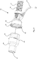
- Fig. 2 shows in perspective the details of the expiratory tube 13 of the preferred embodiment of the breathing tube of the present invention.
- the tube section 17 has a heating coil 18 designed as an electric heater, which is integrated into the tube wall.
- the cylindrical coupling part 19 is connected to the hose section 17, wherein the heating coil 18 is electrically connected to the electrical heating device not visible from the outside in the coupling part 19. If the heating coil 18 of the hose section 17 carries a heating current, then it also flows in the heating device of the coupling part 19. Alternatively, it is conceivable to electrically connect the heating device of the coupling part 19 separately and to control it, for example via the connecting element 21, laterally on the coupling part 19 a sleeve member is arranged.
- the coupling part 19 has a flange 22 which comprises a plurality of closure elements 23 on its inside.
- the coupling part 19 has a cylindrical cavity for receiving the filter element 20.
- the connecting part 15 Connectable to the coupling part 19 is the connecting part 15, which has a cylindrical shape on the coupling side with substantially the same cross-sectional dimension as the coupling part 19.
- closure elements 25 formed on the outside as projections are arranged, which are suitable for engaging in the closure elements 23 of the coupling part 19 in the manner of a bayonet closure.
- other releasable connection mechanisms may be used, e.g. B. screw, magnetic closure, buckle or other familiar to the expert types of connection.
- connection part 15 passes from the section of larger cross-section, which is connectable to the coupling part 19, funnel-like manner into a cylindrical portion 27 of smaller cross-section, which is suitable for connection to a correspondingly designed counterpart of a ventilator.
- the connecting part 15 also has a cylindrical cavity in which the filter element 20 is received.
- the gas mixture flow in operation, d. H. can not completely prevent at the intended connection of connector 15 with coupling part 19.
- the attachment of the filter element 20 between the coupling part 19 and connector 15 must ensure both the sufficient heat transfer from the heater of the coupling part 19 and the sufficient gas mixture flow through the breathing tube.
- connection part 15 is also provided with a heating device which is suitable for heating the filter element 20.
- a heating device which is suitable for heating the filter element 20. This can be done, for example, by an electric heating coil integrated in the jacket surface of the connection part 15, which can be electrically connected to the heating device via the closure elements, in the embodiment shown here via the elements of the bayonet closure. This creates an electrical connection between the heating device of the coupling part 19 and the heating device of the connection part 15.
- Other types of heating devices are also possible.
- connecting element 21 is not arranged on the coupling part 19, but on the connecting part 15. The electrical connection between the two heating devices can then be fed alternatively via the connecting element 21.
- a breathing tube which enables the filtering of the exhalation gas effectively, reliably and permanently, prevents the condensation of water in the filter and minimizes the number of additional elements such as hoses, electrical lines and their connections and the like.
Description
- Die vorliegende Erfindung betrifft einen Beatmungsschlauch für das Durchleiten eines Gasgemisches in einem Beatmungsgerät zum Beatmen von Patienten sowie ein Beatmungsschlauchsystem.
- Bei der maschinellen Beatmung von Patienten, die beispielsweise auf einer Intensivstation liegen, wird der zu beatmende Patient mit Hilfe eines Beatmungsschlauchsystems pneumatisch mit dem Beatmungsgerät verbunden. Da das Atemgas, das dem Patienten zugeführt wird, hinsichtlich Temperatur und Feuchtigkeit den physiologischen Erfordernissen des Patienten angepasst werden muss, wird ein Atemluftbefeuchter in dem Einatem- oder Inspirationsschlauch angeordnet, der das Atemgas anwärmt und anfeuchtet. Der Atemluftbefeuchter weist einen in üblicher Weise mit destilliertem Wasser gefüllten Flüssigkeitsbehälter auf, durch den das Einatemgas geleitet und mit Feuchtigkeit angereichert wird.
- Um eine Kondensation von Feuchtigkeit innerhalb des Beatmungsschlauchsystems zu verhindern, sind der Inspirationsschlauch und der Exspirations- oder Ausatemschlauch mit einer elektrischen Schlauchheizung versehen, die in Betrieb das durchströmende Ein- oder Ausatemgas erwärmt. Dabei wird beispielsweise eine sich integral innerhalb des Inspirations- oder Exspirationsschlauchs erstreckende Heizdrahtschleife verwendet oder der Inspirations- oder Exspirationsschlauch ist jeweils mit einer Heizdrahtwendel umwickelt.
- Derartige Beatmungsschlauchsysteme sind zum Beispiel aus der
DE 10 2008 039 137 B3 , derDE 10 2007 003 455 A1 oder derDE 44 41 380 A1 bekannt. - Im exspiratorischen Teil des Beatmungsschlauchsystems können insbesondere bei Patienten mit ansteckenden Krankheiten Filter eingesetzt werden, um zu verhindern, dass mit dem Ausatemgas Krankheitserreger in die Umgebung gelangen, wodurch sich weitere Patienten oder Betreuungspersonal anstecken könnten. Ein solcher Filter muss so ausgelegt sein, dass sich darin kein Kondensat bildet, weil dies den Filter verstopfen und dadurch die Filterfunktion beeinträchtigen kann. Im schlimmsten Fall kann auch die Beatmungsfunktion fehlerhaft sein, was zu negativen Folgen für den Patienten führen kann. Üblicherweise wird dies mit zusätzlichen Heizvorrichtungen und/oder mit Wasserfallen erreicht, wie beispielsweise in der
US 4,727,871 offenbart. Die allgemeine Verwendung eines Filterelements bei Beatmungsgeräten ist beispielsweise in derUS 3,556,097 offenbart. - Die
GB 1 294 307 A - Die
EP 1 222 940 A2 offenbart eine Anästhesiefilteranordnung mit einem einteiligen Gehäuse mit einer oberen und unteren Öffnung für des Atemgasdurchfluss, wobei im Inneren des Gehäuses ein Filterelement quer zur Atemgasflussrichtung angeordnet ist. Innerhalb des Filterelementvolumens ist ein resistives Heizelement angeordnet, um das Filterelement zu erwärmen. - Die
GB 2 277 689 A - Die
EP 1 222 940 A2 und dieGB 2 277 689 A - Nachteilig an den oben erwähnten Beatmungsschlauchsystemen des Standes der Technik ist, dass die Beheizung von Filtern zusätzliche Bauelemente wie Kabel, Anschlüsse usw. erforderlich macht, was aufgrund der Vielzahl von zu verbindenden Kabeln und Schläuchen zu Zeitverlust und möglicher Verwirrung beim Bedienpersonal führen kann, störend in der Patientenumgebung und anfällig für Beschädigungen ist. Die alternative Verwendung von nicht beheizten Filtern birgt die Gefahren des Verstopfens aufgrund von Kondensatbildung wie oben beschrieben.
- Es ist daher die Aufgabe der vorliegenden Erfindung, einen Beatmungsschlauch bereit zu stellen, der die Filterung des Ausatemgases wirksam, zuverlässig und dauerhaft ermöglicht, die Kondensation von Wasser im Filter verhindert und die Anzahl zusätzlichen Elementen wie Schläuchen, elektrischen Leitungen sowie deren Anschlüsse und dergleichen minimiert.
- Diese Aufgabe wird durch die Merkmale des Anspruchs 1 gelöst. Vorteilhafte Ausgestaltungen und Ausführungsformen sind Gegenstand der Unteransprüche.
- Erfindungsgemäß wird ein Beatmungsschlauch für das Durchleiten eines Gasgemisches in einem Beatmungssystem bereitgestellt mit den Merkmalen des Anspruchs 1 Durch die Wärmeübertragung z. B. durch Konvention oder Wärmeleitung von Koppelteil auf das Filterelement wird sichergestellt, dass sich bei der Filterung des Gasgemisches kein Kondensat bildet, das das Filterelement bzw. den Filter verstopfen könnte. Weiterhin ist der Beatmungsschlauch einfach und platzsparend aufgebaut und kommt außer dem Anschlussteil ohne zusätzliche Elemente aus.
- Mit besonderem Vorteil sind das Filterelement und das Anschlussteil integral ausgebildet. Dadurch ergibt sich eine weitere Vereinfachung des Beatmungsschlauchs, weil weniger Bauelemente erforderlich sind.
- Bevorzugt weisen der Schlauchabschnitt, das Koppelteil und das Anschlussteil einen kreisförmigen Querschnitt auf. Damit können handelsübliche, zylinderförmige Filterelemente verwendet werden. Die Handhabung wie das Zusammensetzen oder gegebenenfalls das Zerlegen der einzelnen Elemente ist ebenfalls vereinfacht.
- Mit weiterem Vorteil ist die Verbindung zwischen Koppelteil und Anschlussteil lösbar als Schraub-, Steck- oder Bajonettverschluss ausgebildet. Derartige Verschlüsse sind leicht zu öffnen und zu schließen, was die Handhabung erleichtert, und deren Anwendung ist im Klinikbereich nicht ungewöhnlich.
- Damit der Beatmungsschlauch bei aktuellen Beatmungsgeräten in Kliniken eingesetzt werden kann, ist er vorteilhafter Weise als medizinischer Einmal-/Wegwerfartikel ausgebildet.
- Bevorzugt weist der Schlauchabschnitt eine zweite elektrische Heizvorrichtung auf, die mit der ersten elektrischen Heizvorrichtung verbindbar ist. Mit weiterem Vorteil sind die erste und/oder die zweite elektrische Heizvorrichtung zumindest abschnittsweise als Heizwendel ausgebildet. Dabei ist die zweite elektrische Heizvorrichtung bevorzugt in die Wand des Schlauchabschnitts integriert. Eine Heizwendel stellt eine einfache Konstruktion dar und sorgt für eine wirksame Beheizung des Beatmungsschlauchs und damit für eine Wärmeübertragung auf das Gasgemisch im Beatmungsschlauch. Die Verbindung zwischen der ersten und zweiten elektrischen Heizvorrichtung ist durch einfache Steckverbinder möglich, die preiswert und robust sind.
- Weiterhin sind vorteilhafter Weise der Schlauchabschnitt und das Koppelteil integral ausgebildet. Auch dadurch ergibt sich eine besonders einfache Konstruktion, beispielsweise durch Koextrusion der Bauelemente. Je weniger Elemente der Beatmungsschlauch bzw. das gesamte Beatmungsschlauchsystem aufweisen, desto geringer ist der Aufwand für das Bedienpersonal beim Zusammensetzen und dergleichen.
- Durch die Anordnung von Koppelteil und Filterelement wird eine maximale Wärmeübertragung von der ersten elektrischen Heizvorrichtung auf das Filterelement ermöglicht. Die Wärmeübertragung erfolgt dabei beispielsweise durch Konvektion oder auch durch Wärmeleitung. Es dabei darauf zu achten, dass die Filterfunktion des Filterelements nicht beeinträchtigt wird, d. h. das Gasgemisch muss in der gewünschten Strömungsgeschwindigkeit durch den Filter fließen können, um die Beatmungsfunktion nicht zu beeinträchtigen.
- Das Filterelement ist dabei bevorzugt zylinderförmig ausgebildet ist, wobei der Abstand zwischen äußerer Mantelfläche des Filterelements und innerer Mantelfläche des Koppelteils ungefähr 0,1 mm bis etwa 8 mm beträgt. Derartige zylinderförmige Filter werden industriell hergestellt und sind kommerziell erhältlich. Ein Beispiel für die Konstruktion eines solchen Filters ohne Beheizung vom Prinzip her ist in den Fig. 11 bis 13 der
US 3,556,097 dargestellt. Hierbei wird ein ringförmiger Filter axial innerhalb eines Gehäuses angeordnet, und das Atemgas strömt von der äußeren Mantelfläche des Rings durch das Filtermaterial hindurch zur inneren Mantelfläche und von dort durch die Ausströmöffnung des Gehäuses. Es versteht sich jedoch, dass bei der vorliegenden Erfindung auch andere Konstruktionen von Filterelementen mit Anschluss- und Koppelteil verwendet werden können. Beispielsweise ist ein im Wesentlichen kugelförmiges Filterelement denkbar, das einen Hohlraum aufweist, in den das Gasgemisch von der äußeren Oberfläche durch das Filtermaterial hindurch strömt. - Mit weiterem Vorteil weist der Beatmungsschlauch einen Sensor zur Erfassung von Parametern der Verbindung zwischen Koppelteil und Anschlussteil auf. Damit lässt sich über eine Benutzerschnittstelle, beispielsweise eines Atemluftbefeuchter oder auf eines Beatmungsgerätes, eine Anzeige aktivieren, die die ordnungsgemäße Verbindung zwischen Koppelteil und Anschlussteil anzeigt. Damit kann die Funktion des Filterelements besser überwacht, fehlerhafte Montage bzw. Fehlfunktionen können schneller erkannt werden.
- Mit besonderem Vorteil weist das Anschlussteil eine elektrische Heizvorrichtung auf, die elektrisch mit der Heizvorrichtung des Koppelteils verbindbar ist. Dadurch kann die Heizleistung für das Filterelement verstärkt werden, wobei eine einfache elektrische Anbindung beispielsweise über die Verschlusselemente von Koppelteil und Anschlussteil erfolgen kann. Damit kann auch die oben genannte Funktion eines Sensors realisiert sein, wobei beispielsweise das Vorliegen einer wirksamen elektrischen Verbindung zwischen Koppelteil und Anschlussteil die ordnungsgemäße Verbindung angibt. Alternativ kann die Heizvorrichtung des Anschlussteils und gegebenenfalls des Koppelteils auch über ein Verbindungselement gespeist sein, das direkt mit dem Anschlussteil verbunden ist.
- Weiterhin erfindungsgemäß ist ein Beatmungsschlauchsystem mit einem Inspirationsschlauch und einem Exspirationsschlauch, der als Beatmungsschlauch wie oben erwähnt ausgebildet ist.
- Die Erfindung soll nachfolgend anhand von Ausführungsbeispielen unter Bezugnahme auf die beigefügten Figuren erläutert werden, in denen:
- Fig. 1
- eine schematische Darstellung einer bevorzugten Ausführungsform des Beatmungsschlauchsystems der vorliegenden Erfindung zeigt; und
- Fig. 2
- eine perspektivische Ansicht einer bevorzugten Ausführungsform des Beatmungsschlauchs gemäß der vorliegenden Erfindung zeigt.
-
Fig. 1 zeigt eine perspektivische Darstellung des erfindungsgemäßen Beatmungsschlauchssystems. Ein (inFig. 1 nicht dargestelltes) Beatmungsgerät ist über ein erstes Anschlusselement mit einem ersten Inspirationsschlauch 3 verbunden. Dieser erste Inspirationsschlauch 3 sowie ein zweiter Inspirationsschlauch 5 sind über entsprechende Anschlussstücke 7, 9 mit einem Flüssigkeitsbehälter 11 eines (inFig. 1 nicht dargestellten) Atemluftbefeuchters verbunden. Das freie Ende des zweiten Inspirationsschlauchs 5 ist mit einem (ebenfalls nicht dargestellten) Y-Stück verbindbar, das die Verbindung zum Patienten über ein Mundstück herstellt. Sowohl der erste als auch der zweite Inspirationsschlauch 3 bzw. 5 ist mit einer elektrischen Schlauchheizung ausgestattet, die als Heizwendel in die Schlauchwand integriert ist. InFig. 1 ist lediglich die pneumatische Verbindung zwischen erstem und zweitem Inspirationsschlauch 3, 5 und dem Flüssigkeitsbehälter 11 über die Anschlussstücke 7, 9 dargestellt, da die elektrische Verbindung sämtlicher in Schläuchen verlaufender elektrischen Verbindungen über Kontaktelemente erfolgt, die in die Anschlussstücke 7, 9 integriert sind und den elektrischen Kontakt zu entsprechenden Gegenstück der Kontaktelemente an dem Gehäuse des Atemluftbefeuchters herstellen. Ein Exspirationsschlauch 13 ist über ein Anschlussteil 15 mit dem Beatmungsgerät verbindbar. Das andere Ende des Exspirationsschlauchs 13 wird in Betrieb mit dem Y-Stück nahe am Patienten verbunden. - Der Exspirationsschlauch 13 stellt in der hier gezeigten Ausführungsform den erfindungsgemäßen Beatmungsschlauch dar und weist einen Schlauchabschnitt 17 auf, der mit einer in die Schlauchwand integrierten, als Heizwendel ausgebildeten elektrischen Heizvorrichtung 19 versehen ist. Zwischen Anschlussteil 15 und Schlauchabschnitt 17 weist der Exspirationsschlauch 13 ein Koppelteil 19 mit Filterelement 20 auf, wobei das Koppelteil 19 fest mit dem Schlauchabschnitt 17 und lösbar mit dem Anschlussteil 15 verbunden ist. Die Einzelheiten des Exspirationsschlauchs sind unter Bezugnahme auf
Fig. 2 beschrieben. - Ein Verbindungselement 21 ist in der
Fig. 2 dargestellten Ausführungsform zwischen dem Anschlussstück 2 des ersten Inspirationsschlauchs 3 und dem Koppelteil 19 des Exspirationsschlauchs 13 zur elektrischen Verbindung angeordnet. Das Anschlussstück 2 des ersten Inspirationsschlauchs 3 weist neben der pneumatischen Öffnung ein Hülsenelement auf, in das ein entsprechendes Steckelement des Verbindungselements 21 unlösbar eingesteckt ist. In gleicher Weise weist das Koppelteil 19 des Exspirationsschlauches 13 ein Hülsenelement auf, in die das entsprechende Steckelement des Verbindungselements 21 unlösbar eingesteckt ist. Der Begriff "unlösbar" ist in diesem Zusammenhang so zu verstehen, dass es für Bedienpersonal nicht ohne Weiteres möglich ist, die elektrischen Verbindungen zwischen Verbindungselement 21 und dem Anschlussstück 2 bzw. dem Koppelteil 19 zu lösen. - Da die Darstellung in
Fig. 1 die Elemente betrifft, die üblicher Weise als medizinische Einmal-/Wegwerfartikel das notwendige austauschbare Zubehör für die Funktion eines Atemluftbefeuchters zusammen mit dem Beatmungsschlauchsystem bilden, sind Elemente wie das Y-Stück oder das Gehäuse des Atemluftbefeuchters an dieser Stelle weggelassen. - Das Material für die Schläuche, d. h. für den ersten Inspirationsschlauch 3, den zweiten Inspirationsschlauch 5 und den Exspirationsschlauch 13 ist aus einem geeigneten Kunststoffmaterial wie z. B. Polyethylen oder Polypropylen gebildet. Andere geeignete Materialien sind ebenfalls möglich. Die Schläuche werden in bekannter Technik extrudiert bzw. koextrudiert. Der Innendurchmesser der Schläuche beträgt üblicher Weise etwa 19 mm oder etwa 22 mm bei einem Beatmungssystem für Erwachsene, es können auch geringere Durchmesser wie 12 mm oder 15 mm verwendet werden, beispielsweise für Beatmungssysteme in Kinder- oder Säuglingsintensivstationen. Die Anschlussstücke, die den Übergang zwischen den Schläuchen der entsprechenden Geräte bzw. dem Y-Stück bilden, sind ebenfalls aus Kunststoffmaterial extrudiert. Da im medizinischen Bereich an die Materialien hohe Anforderungen gestellt werden, müssen die Materialen der ISO-Norm 5367-2000 genügen. Wie bereits erwähnt ist das erfindungsgemäße Beatmungsschlauchsystem entweder als medizinischer Einmal-/Wegwerfartikel ausgebildet oder alternativ als wieder verwendbarer medizinischer Artikel, der mittels Waschen und Autoklavieren wieder in einen neu verwendbaren Zustand versetzt werden kann. Alle Bestandteile des Beatmungsschlauchsystems müssen auch derart ausgebildet sein, dass sie beispielsweise keine Schadstoffe enthalten und einem kalten Desinfektionsmittel wie z.B. CIDEX, Sekusept, Korsolex usw. widerstehen.
-
Fig. 2 zeigt in perspektivischer Darstellung die Einzelheiten des Exspirationsschlauchs 13 der bevorzugten Ausführungsform des Beatmungsschlauches der vorliegenden Erfindung. Der Schlauchabschnitt 17 weist eine als Heizwendel 18 ausgebildete elektrische Heizvorrichtung auf, die in die Schlauchwand integriert ist. Das zylinderförmige Koppelteil 19 ist mit dem Schlauchabschnitt 17 verbunden, wobei die Heizwendel 18 elektrisch mit der in das Koppelteil 19 von außen nicht sichtbar integrierten elektrischen Heizvorrichtung in Verbindung steht. Führt die Heizwendel 18 des Schlauchabschnitts 17 einen Heizstrom, so fließt dieser auch in der Heizvorrichtung des Koppelteils 19. Alternativ ist es denkbar, die Heizvorrichtung des Koppelteils 19 separat elektrisch zu verbinden und beispielsweise über das Verbindungselement 21 zu steuern, das seitlich am Koppelteil 19 über ein Hülsenelement angeordnet ist. In der inFig. 2 dargestellten Ausführungsform weist das Koppelteil 19 einen Flansch 22 auf, der auf seiner Innenseite eine Mehrzahl von Verschlusselementen 23 umfasst. Das Koppelteil 19 weist einen zylinderförmigen Hohlraum für die Aufnahme des Filterelements 20 auf. - Mit dem Koppelteil 19 verbindbar ist das Anschlussteil 15, das auf der Koppelseite zylinderförmig mit im Wesentlichen demselben Querschnittsmaß wie das Koppelteil 19 aufweist. Auf der Mantelfläche des Anschlussteils 15 sind außen als Vorsprünge ausgebildete Verschlusselemente 25 angeordnet, die dazu geeignet sind, in die Verschlusselemente 23 des Koppelteils 19 nach Art eines Bajonettverschlusses einzugreifen. Alternativ können auch andere lösbare Verbindungsmechanismen verwendet werden, z. B. Schraubverschluss, Magnetverschluss, Steckverschluss oder andere dem Fachmann geläufige Verbindungsarten.
- Das Anschlussteil 15 geht vom Abschnitt größeren Querschnitts, der mit dem Koppelteil 19 verbindbar ist, trichterartig in einen zylinderförmigen Abschnitt 27 kleineren Querschnitts über, der zur Verbindung mit einem entsprechend ausgebildeten Gegenstück eines Beatmungsgerät geeignet ist. Das Anschlussteil 15 weist ebenfalls einen zylinderförmigen Hohlraum auf, in dem das Filterelement 20 aufgenommen ist. Zur Fixierung des Filterelements 20 innerhalb des Hohlraums können Aufnahmeelemente vorgesehen sein, die jedoch den Gasgemischfluss in Betrieb, d. h. bei bestimmungsgemäßer Verbindung von Anschlussteil 15 mit Koppelteil 19 nicht vollständig verhindern dürfen. Mit anderen Worten, die Befestigung des Filterelements 20 zwischen Koppelteil 19 und Anschlussteil 15 muss sowohl die ausreichende Wärmeübertragung von der Heizvorrichtung des Koppelteils 19 als auch den ausreichenden Gasgemischfluss durch den Beatmungsschlauch sicherstellen.
- Deshalb sind innerhalb von Koppelteil 19 und Anschlussteil 15 verschiedene Konstruktionen möglich, die von der in
Fig. 2 dargestellten Ausführungsform abweichen, jedoch die oben genannte Funktion erfüllen. - Es ist ebenfalls denkbar, dass auch das Anschlussteil 15 mit einer Heizvorrichtung versehen ist, die geeignet ist, das Filterelement 20 aufzuheizen. Dies kann beispielsweise durch eine in die Mantelfläche des Anschlussteils 15 integrierte elektrische Heizwendel erfolgen, die über die Verschlusselemente, in der hier dargestellten Ausführungsform über die Elemente des Bajonettverschlusses, elektrisch mit der Heizvorrichtung verbindbar ist. Dadurch entsteht eine elektrische Verbindung zwischen der Heizvorrichtung des Koppelteils 19 mit der Heizvorrichtung des Anschlussteils 15. Es sind auch andere Arten von Heizvorrichtungen möglich.
- Weiterhin ist es möglich, dass das Verbindungselement 21 nicht am Koppelteil 19, sondern am Anschlussteil 15 angeordnet ist. Die elektrische Verbindung zwischen den beiden Heizvorrichtungen kann dann alternativ über das Verbindungselement 21 gespeist werden.
- Mit dem Gegenstand der vorliegenden Erfindung wurde ein Beatmungsschlauch bereit gestellt, der die Filterung des Ausatemgases wirksam, zuverlässig und dauerhaft ermöglicht, die Kondensation von Wasser im Filter verhindert und die Anzahl zusätzlichen Elementen wie Schläuchen, elektrischen Leitungen sowie deren Anschlüsse und dergleichen minimiert.
Claims (14)
- Beatmungsschlauch (13) für das Durchleiten eines Gasgemisches in einem Beatmungssystem mit
einem Schlauchabschnitt (17),
einem mit dem Schlauchabschnitt (17) fest verbundenen Koppelteil (19),
einem Anschlussteil (15), das an einen Schlauch oder ein Gerät anschließbar ist,
wobei zwischen dem Koppelteil (19) und dem Anschlussteil (15) ein Filterelement (20) zur Filterung des Gasgemisches angeordnet ist, und
einer ersten elektrischen Heizvorrichtung, die das Filterelement (20) umschließt und dadurch geeignet ist, das Filterelement (20) wirksam aufzuheizen, wobei das Koppelteil (19) lösbar mit dem Anschlussteil (15) verbunden ist und die erste elektrische Heizvorrichtung in das Koppelteil (19) integriert ist. - Beatmungsschlauch (13) nach Anspruch 1, dadurch gekennzeichnet, dass das Filterelement (20) und das Anschlussteil (15) integral ausgebildet sind.
- Beatmungsschlauch (13) nach einem der vorhergehenden Ansprüche, dadurch gekennzeichnet, dass der Schlauchabschnitt (17), das Koppelteil (19) und das Anschlussteil (15) einen kreisförmigen Querschnitt aufweisen.
- Beatmungsschlauch (13) nach einem der vorhergehenden Ansprüche, dadurch gekennzeichnet, dass die Verbindung zwischen Koppelteil (19) und Anschlussteil (15) lösbar als Schraub-, Steck- oder Bajonettverschluss ausgebildet ist.
- Beatmungsschlauch (13) nach einem der vorhergehenden Ansprüche, dadurch gekennzeichnet, dass er als medizinischer Einmal-/Wegwerfartikel ausgebildet ist.
- Beatmungsschlauch (13) nach einem der vorhergehenden Ansprüche, dadurch gekennzeichnet, dass der Schlauchabschnitt (17) eine zweite elektrische Heizvorrichtung (18) aufweist, die mit der ersten elektrischen Heizvorrichtung verbindbar ist.
- Beatmungsschlauch (13) nach einem der vorhergehenden Ansprüche, dadurch gekennzeichnet, dass die erste und/oder die zweite elektrische Heizvorrichtung zumindest abschnittsweise als Heizwendel ausgebildet sind.
- Beatmungsschlauch (13) nach Anspruch 6 oder 7, dadurch gekennzeichnet, dass die zweite elektrische Heizvorrichtung in die Wand des Schlauchabschnitts (17) integriert ist.
- Beatmungsschlauch (13) nach einem der vorhergehenden Ansprüche, dadurch gekennzeichnet, dass der Schlauchabschnitt (17) und das Koppelteil (19) integral ausgebildet sind.
- Beatmungsschlauch (13) nach einem der vorhergehenden Ansprüche, dadurch gekennzeichnet, dass die Anordnung von Koppelteil (19) und Filterelement (20) eine maximale Wärmeübertragung von der ersten elektrischen Heizvorrichtung auf das Filterelement (20) ermöglicht.
- Beatmungsschlauch (13) nach Anspruch 10, dadurch gekennzeichnet, dass das Filterelement (20) zylinderförmig ausgebildet ist, wobei der Abstand zwischen äußerer Mantelfläche des Filterelements (20) und innerer Mantelfläche des Koppelteils (19) ungefähr 0,1 mm bis etwa 8 mm beträgt.
- Beatmungsschlauch (13) nach einem der vorhergehenden Ansprüche, dadurch gekennzeichnet, dass er einen Sensor zur Erfassung von Parametern der Verbindung zwischen Koppelteil (19) und Anschlussteil (15) aufweist.
- Beatmungsschlauch (13) nach einem der vorhergehenden Ansprüche, dadurch gekennzeichnet, dass das Anschlussteil (15) eine weitere elektrische Heizvorrichtung aufweist, die elektrisch mit der Heizvorrichtung des Koppelteils (19) verbindbar ist.
- Beatmungsschlauchsystem mit einem Inspirationsschlauch (3, 5) und einem Exspirationsschlauch (13), der als Beatmungsschlauch nach einem der vorhergehenden Ansprüche ausgebildet ist.
Applications Claiming Priority (2)
| Application Number | Priority Date | Filing Date | Title |
|---|---|---|---|
| DE102012101795A DE102012101795A1 (de) | 2012-03-02 | 2012-03-02 | Beatmungsschlauch |
| PCT/EP2012/069147 WO2013127474A1 (de) | 2012-03-02 | 2012-09-27 | Beatmungsschlauch |
Publications (2)
| Publication Number | Publication Date |
|---|---|
| EP2819732A1 EP2819732A1 (de) | 2015-01-07 |
| EP2819732B1 true EP2819732B1 (de) | 2017-05-03 |
Family
ID=47040689
Family Applications (1)
| Application Number | Title | Priority Date | Filing Date |
|---|---|---|---|
| EP12773280.8A Active EP2819732B1 (de) | 2012-03-02 | 2012-09-27 | Beatmungsschlauch |
Country Status (8)
| Country | Link |
|---|---|
| US (2) | US10105510B2 (de) |
| EP (1) | EP2819732B1 (de) |
| JP (1) | JP6053057B2 (de) |
| KR (1) | KR101670320B1 (de) |
| CN (1) | CN104203325B (de) |
| DE (1) | DE102012101795A1 (de) |
| ES (1) | ES2626615T3 (de) |
| WO (1) | WO2013127474A1 (de) |
Families Citing this family (52)
| Publication number | Priority date | Publication date | Assignee | Title |
|---|---|---|---|---|
| US9505164B2 (en) | 2009-12-30 | 2016-11-29 | Schauenburg Technology Se | Tapered helically reinforced hose and its manufacture |
| DE102008022663B4 (de) | 2008-05-07 | 2012-10-31 | Schauenburg Hose Technology Gmbh | Stretch-Schlauch |
| US9964238B2 (en) | 2009-01-15 | 2018-05-08 | Globalmed, Inc. | Stretch hose and hose production method |
| RU2657935C2 (ru) | 2011-06-03 | 2018-06-18 | Фишер Энд Пейкел Хелткэа Лимитед | Медицинские трубки и способы их изготовления |
| GB2554628B (en) | 2011-08-10 | 2018-10-03 | Fisher & Paykel Healthcare Ltd | Connector assembly for a patient breathing device |
| EP3738638A1 (de) | 2012-03-15 | 2020-11-18 | Fisher & Paykel Healthcare Limited | Atemgasbefeuchtungssystem |
| IN2014MN02333A (de) | 2012-04-27 | 2015-08-14 | Fisher & Paykel Healthcare Ltd | |
| CN107361960B (zh) | 2012-11-14 | 2020-11-06 | 费雪派克医疗保健有限公司 | 用于呼吸回路的分区加热 |
| CN116585583A (zh) | 2012-12-04 | 2023-08-15 | 费雪派克医疗保健有限公司 | 医用管以及其制造方法 |
| CA3166029A1 (en) | 2013-09-13 | 2015-03-19 | Fisher And Paykel Healthcare Limited | Circuit connector for a humidification system |
| EP3043854B1 (de) | 2013-09-13 | 2019-11-06 | Fisher & Paykel Healthcare Limited | Befeuchtungssystem |
| USD751688S1 (en) * | 2013-09-26 | 2016-03-15 | The Periodic Breathing Foundation, Llc | Tubing set interface |
| USD751687S1 (en) * | 2013-09-26 | 2016-03-15 | The Periodic Breathing Foundation, Llc | Tubing set |
| US10814091B2 (en) | 2013-10-24 | 2020-10-27 | Fisher & Paykel Healthcare Limited | System for delivery of respiratory gases |
| CA3176263A1 (en) | 2013-12-20 | 2015-06-25 | Fisher & Paykel Healthcare Limited | Humidification system connections |
| US10449319B2 (en) | 2014-02-07 | 2019-10-22 | Fisher & Paykel Healthcare Limited | Respiratory humidification system |
| CN106232167B (zh) | 2014-03-17 | 2020-03-24 | 费雪派克医疗保健有限公司 | 用于呼吸系统的医用管 |
| USD762843S1 (en) | 2014-03-18 | 2016-08-02 | Resmed Limited | Air delivery tube |
| WO2015167347A1 (en) | 2014-05-02 | 2015-11-05 | Fisher & Paykel Healthcare Limited | Gas humidification arrangement |
| AU2015259944B2 (en) | 2014-05-13 | 2020-07-02 | Fisher & Paykel Healthcare Limited | Usability features for respiratory humidification system |
| EP3151894B1 (de) | 2014-06-03 | 2019-08-28 | Fisher & Paykel Healthcare Limited | Strömungsmischer für atemtherapiesysteme |
| EP3925654B1 (de) | 2014-11-17 | 2024-04-17 | Fisher & Paykel Healthcare Limited | Befeuchtung von atemgasen |
| US11446462B2 (en) * | 2015-03-31 | 2022-09-20 | Fisher & Paykel Healthcare Limited | Apparatus for use in a respiratory support system |
| WO2017043981A1 (en) | 2015-09-09 | 2017-03-16 | Po-Yen Liu | Zone heating for respiratory circuits |
| USD807995S1 (en) | 2015-09-22 | 2018-01-16 | Fisher & Paykel Healthcare Limited | Circuit kit for a humidifier |
| USD841147S1 (en) * | 2015-09-30 | 2019-02-19 | Fisher & Paykel Healthcare Limited | Circuit kit for a humidifier |
| USD805630S1 (en) | 2016-02-02 | 2017-12-19 | Resmed Limited | Air delivery tube |
| USD841148S1 (en) * | 2016-07-21 | 2019-02-19 | Fisher & Paykel Healthcare Limited | Breathing tube |
| USD847326S1 (en) * | 2016-11-03 | 2019-04-30 | Koninklijke Philips N.V. | Positive airway pressure tube for sleep therapy |
| USD882757S1 (en) * | 2016-11-30 | 2020-04-28 | ResMed Pty Ltd | Respiratory mask air delivery adapter assembly |
| CN106730228B (zh) * | 2016-12-07 | 2023-11-07 | 天津怡和嘉业医疗科技有限公司 | 湿化装置、加热管路及其转接口、湿化加热组件和呼吸机 |
| EP3551978B1 (de) | 2016-12-07 | 2022-01-26 | Fisher&Paykel Healthcare Limited | Erfassungsanordnungen für medizinische vorrichtungen |
| EP3544662A4 (de) | 2016-12-22 | 2020-07-29 | Fisher & Paykel Healthcare Limited | Medizinische schläuche und verfahren zur herstellung |
| CA3053834C (en) | 2017-01-30 | 2020-09-01 | Globalmed, Inc. | Heated respiratory hose assembly |
| US10857397B2 (en) * | 2017-07-26 | 2020-12-08 | Honeywell International Inc. | Bayonet hose connector assembly mechanism in powered air purifying air respirator housing |
| USD895788S1 (en) * | 2018-01-30 | 2020-09-08 | Inovytec Medical Solutions Ltd. | Patient circuit for gas delivery |
| US11305079B2 (en) * | 2018-05-08 | 2022-04-19 | Optimal Breathing, Llc | Oxygen enhanced exercise and rest system |
| USD894376S1 (en) | 2018-05-23 | 2020-08-25 | Fisher & Paykel Healthcare Limited | Insufflation circuit assembly |
| USD894379S1 (en) | 2018-05-23 | 2020-08-25 | Fisher & Paykel Healthcare Limited | Insufflation circuit and filter |
| JP7260307B2 (ja) * | 2019-01-21 | 2023-04-18 | 日本無機株式会社 | 人工呼吸器、及び人工呼吸システム |
| CN109966617B (zh) * | 2019-03-18 | 2021-07-02 | 小牛科技河北有限公司 | 呼吸机接头及呼吸机 |
| DE102019119674A1 (de) * | 2019-07-19 | 2021-01-21 | Hamilton Medical Ag | Beatmungsleitung mit verbessert austauschbarem Atemgas-Filter |
| USD930150S1 (en) | 2019-08-21 | 2021-09-07 | ResMed Asia Pte Ltd | Patient interface |
| USD933814S1 (en) | 2019-08-23 | 2021-10-19 | ResMed Pty Ltd | Patient interface |
| USD941993S1 (en) | 2019-08-23 | 2022-01-25 | ResMed Pty Ltd | Tube headgear for patient interface |
| USD1006981S1 (en) | 2019-09-06 | 2023-12-05 | Fisher & Paykel Healthcare Limited | Breathing conduit |
| USD948027S1 (en) | 2019-09-10 | 2022-04-05 | Fisher & Paykel Healthcare Limited | Connector for a breathing conduit |
| KR20210106748A (ko) | 2020-02-21 | 2021-08-31 | 주식회사 멕 아이씨에스 | 호흡 튜브 |
| KR102267814B1 (ko) * | 2020-05-28 | 2021-06-21 | 실내공기질안전지킴이사회적협동조합연합회 | 방역효율성을 높인 수직기류형 환기시스템 |
| DE202020105802U1 (de) * | 2020-10-09 | 2020-12-02 | Gerhard Müller | Beatmungssystem |
| USD974551S1 (en) | 2020-12-09 | 2023-01-03 | Fisher & Paykel Healthcare Limited | Connector assembly and connector |
| USD995758S1 (en) | 2021-06-11 | 2023-08-15 | Fisher & Paykel Healthcare Limited | Tube assembly and connector |
Family Cites Families (25)
| Publication number | Priority date | Publication date | Assignee | Title |
|---|---|---|---|---|
| GB1294307A (en) * | 1968-12-31 | 1972-10-25 | Microflow Ltd | Heated anaesthetic filter |
| US3556097A (en) | 1969-09-25 | 1971-01-19 | Air Reduction | Disposable anesthesia-breathing circuit unit |
| US4306743A (en) * | 1980-03-24 | 1981-12-22 | Hinshaw William E | Safety connection for breathing tubes |
| US4727871A (en) | 1985-10-28 | 1988-03-01 | Infrasonics, Inc. | Ventilator exhalation system |
| GB9309294D0 (en) * | 1993-05-06 | 1993-06-16 | Smiths Ind Public Ltd | Heaters and heated devices |
| US5460172A (en) * | 1993-11-01 | 1995-10-24 | Artema Medical Ab | Moisture and heat exchanging unit for a respiration device |
| GB2284356B (en) | 1993-11-22 | 1997-10-29 | Fisher & Paykel | Respiratory humidifier conduit |
| US5600752A (en) | 1994-03-11 | 1997-02-04 | Industrial Design Laboratories, Inc. | Flexible gas hose assembly with concentric helical tube members having reinforcement spring coils |
| AU1486195A (en) | 1994-03-15 | 1995-09-21 | Fisher & Paykel Limited | A humidifier conduit |
| EP0873148A4 (de) | 1995-11-13 | 1999-12-29 | Fisher & Paykel | Beheiztes beatmungsrohr |
| US7120354B2 (en) * | 2000-03-21 | 2006-10-10 | Fisher & Paykel Healthcare Limited | Gases delivery conduit |
| SE0100064D0 (sv) | 2001-01-10 | 2001-01-10 | Siemens Elema Ab | Anaesthetic filter arrangement |
| US7322566B2 (en) * | 2002-05-29 | 2008-01-29 | Bvba Medisize Belgie | Device for heating and moistening breathing air |
| US7497215B1 (en) | 2002-12-20 | 2009-03-03 | Koninklijke Philips Electronics N.V. | Medical ventilator with compressor heated exhalation filter |
| JP4503322B2 (ja) | 2004-03-22 | 2010-07-14 | 株式会社メトラン | 呼吸回路用の蛇管 |
| US20060096597A1 (en) | 2004-11-09 | 2006-05-11 | Home Health Medical Equipment Incorporated, D/B/A Ag Industries | Swivel filter for use with sleep apnea and other respiratory equipment including associated interface systems |
| DE102005052122A1 (de) * | 2005-10-28 | 2007-05-10 | W.O.M. World Of Medicine Ag | Schlauchset |
| GB0620535D0 (en) | 2006-10-17 | 2006-11-22 | Air Safety Ltd | Filter |
| CN110141752B (zh) * | 2006-11-08 | 2022-03-04 | 瑞思迈私人有限公司 | 在呼吸装置中使用的导管 |
| DE102007003455B4 (de) | 2007-01-18 | 2009-03-05 | Schaller, Peter, Dr.-Ing.habil. | Beheizungssystem für einen Beatmungsschlauch |
| JP5149025B2 (ja) * | 2008-01-31 | 2013-02-20 | テルモ株式会社 | 酸素濃縮装置 |
| DE102008039137B3 (de) | 2008-08-21 | 2010-02-11 | Dräger Medical AG & Co. KG | Beatmungsgerät mit einem Atemschlauchsystem |
| US20110308522A1 (en) * | 2008-12-22 | 2011-12-22 | Koninklijke Philips Electronics N.V. | Gas filter with integrated heating |
| IT1393213B1 (it) | 2009-03-17 | 2012-04-11 | Covidien Ag | Sistema per condizionare i gas respiratori |
| EP2269680B1 (de) * | 2009-06-30 | 2012-09-19 | Covidien AG | System zum Anfeuchten von Atemgasen mit einem konstanten Feuchtigkeitsgrad |
-
2012
- 2012-03-02 DE DE102012101795A patent/DE102012101795A1/de not_active Withdrawn
- 2012-09-27 JP JP2014559113A patent/JP6053057B2/ja active Active
- 2012-09-27 US US14/382,547 patent/US10105510B2/en active Active
- 2012-09-27 ES ES12773280.8T patent/ES2626615T3/es active Active
- 2012-09-27 KR KR1020147027755A patent/KR101670320B1/ko active IP Right Grant
- 2012-09-27 EP EP12773280.8A patent/EP2819732B1/de active Active
- 2012-09-27 CN CN201280070867.3A patent/CN104203325B/zh active Active
- 2012-09-27 WO PCT/EP2012/069147 patent/WO2013127474A1/de active Application Filing
-
2018
- 2018-09-04 US US16/120,888 patent/US10940284B2/en active Active
Also Published As
| Publication number | Publication date |
|---|---|
| US20180369533A1 (en) | 2018-12-27 |
| KR20140131578A (ko) | 2014-11-13 |
| CN104203325A (zh) | 2014-12-10 |
| EP2819732A1 (de) | 2015-01-07 |
| ES2626615T3 (es) | 2017-07-25 |
| WO2013127474A1 (de) | 2013-09-06 |
| US20150128944A1 (en) | 2015-05-14 |
| DE102012101795A1 (de) | 2013-09-05 |
| JP2015508689A (ja) | 2015-03-23 |
| US10940284B2 (en) | 2021-03-09 |
| US10105510B2 (en) | 2018-10-23 |
| KR101670320B1 (ko) | 2016-10-28 |
| JP6053057B2 (ja) | 2016-12-27 |
| CN104203325B (zh) | 2017-11-10 |
Similar Documents
| Publication | Publication Date | Title |
|---|---|---|
| EP2819732B1 (de) | Beatmungsschlauch | |
| EP2760513B1 (de) | Beatmungsschlauchsystem | |
| EP2760517B1 (de) | Verbindungssystem für atemluftbefeuchter | |
| EP2780066B1 (de) | Schlauch für ein beatmungssystem | |
| DE69837926T2 (de) | Umhüllter filter für einen beatmungskreislauf | |
| DE602004013263T2 (de) | Sensorschutzvorrichtung mit Doppelmembran | |
| DE3032438C2 (de) | Y-Stück im Patientensystem von Beatmungsvorrichtungen | |
| EP0413127B1 (de) | Vorrichtung zum Anwärmen und Anfeuchten von Gasen, insbesondere von Atemgasen bei künstlicher Beatmung | |
| DE69921834T2 (de) | Vorrichtung für die zu-und abfuhr von inhalationsgas bei einem patienten | |
| DE202012013743U1 (de) | Leitungsverbinder für eine Vorrichtung zur Beatmung von Patienten | |
| DE60119407T2 (de) | Filter | |
| EP0054714A2 (de) | Konnektions-System mit ineinandersteckbaren Verbindungselementen für Beatmungs- bzw. Anaestesie-Geräte | |
| DE202006007397U1 (de) | Beatmungsschlauch mit unterschiedlichen Heizzonen | |
| EP3484562B1 (de) | Verneblereinheit mit wechselbarem mundstück | |
| EP1457223B1 (de) | Vorrichtung zur Beatmung | |
| DE102007029016B3 (de) | Zusatzgerät für ein medizinisches Basisgerät | |
| DE102012002632A1 (de) | Beatmungssystem und Konnektorsystem hierfür zur Verminderung von Kontaminationen | |
| EP3852853B1 (de) | System zur unterstützung der atmung | |
| DE102011014018A1 (de) | Vorrichtung zum Filtern von Atemgas | |
| DE60206165T2 (de) | Handteil eines inhalators | |
| EP3981458A1 (de) | Beatmungssystem | |
| WO2021027983A1 (de) | Kopplungsteil für beatmungskreislauf | |
| EP4323042A1 (de) | Hme-vorrichtungen | |
| DE102018103665A1 (de) | Kopplungsteil für Beatmungskreislauf | |
| DE102013018458A1 (de) | Y-Stück für Beatmungssystem, Y-Verzweigungssatz, Verfahren und Vorrichtung zum Herstellen derselben |
Legal Events
| Date | Code | Title | Description |
|---|---|---|---|
| PUAI | Public reference made under article 153(3) epc to a published international application that has entered the european phase |
Free format text: ORIGINAL CODE: 0009012 |
|
| 17P | Request for examination filed |
Effective date: 20140811 |
|
| AK | Designated contracting states |
Kind code of ref document: A1 Designated state(s): AL AT BE BG CH CY CZ DE DK EE ES FI FR GB GR HR HU IE IS IT LI LT LU LV MC MK MT NL NO PL PT RO RS SE SI SK SM TR |
|
| AX | Request for extension of the european patent |
Extension state: BA ME |
|
| DAX | Request for extension of the european patent (deleted) | ||
| 17Q | First examination report despatched |
Effective date: 20160523 |
|
| REG | Reference to a national code |
Ref country code: DE Ref legal event code: R079 Ref document number: 502012010255 Country of ref document: DE Free format text: PREVIOUS MAIN CLASS: A61M0016100000 Ipc: A61M0016080000 |
|
| RIC1 | Information provided on ipc code assigned before grant |
Ipc: A61M 16/10 20060101ALI20160922BHEP Ipc: A61M 16/00 20060101ALI20160922BHEP Ipc: A61M 16/16 20060101ALI20160922BHEP Ipc: A61M 16/08 20060101AFI20160922BHEP |
|
| GRAP | Despatch of communication of intention to grant a patent |
Free format text: ORIGINAL CODE: EPIDOSNIGR1 |
|
| INTG | Intention to grant announced |
Effective date: 20161129 |
|
| RIN1 | Information on inventor provided before grant (corrected) |
Inventor name: BUECHI, RUDOLF |
|
| GRAS | Grant fee paid |
Free format text: ORIGINAL CODE: EPIDOSNIGR3 |
|
| GRAA | (expected) grant |
Free format text: ORIGINAL CODE: 0009210 |
|
| RAP1 | Party data changed (applicant data changed or rights of an application transferred) |
Owner name: HAMILTON MEDICAL AG |
|
| AK | Designated contracting states |
Kind code of ref document: B1 Designated state(s): AL AT BE BG CH CY CZ DE DK EE ES FI FR GB GR HR HU IE IS IT LI LT LU LV MC MK MT NL NO PL PT RO RS SE SI SK SM TR |
|
| REG | Reference to a national code |
Ref country code: GB Ref legal event code: FG4D Free format text: NOT ENGLISH |
|
| REG | Reference to a national code |
Ref country code: AT Ref legal event code: REF Ref document number: 889289 Country of ref document: AT Kind code of ref document: T Effective date: 20170515 Ref country code: CH Ref legal event code: EP |
|
| REG | Reference to a national code |
Ref country code: IE Ref legal event code: FG4D Free format text: LANGUAGE OF EP DOCUMENT: GERMAN |
|
| REG | Reference to a national code |
Ref country code: DE Ref legal event code: R096 Ref document number: 502012010255 Country of ref document: DE |
|
| REG | Reference to a national code |
Ref country code: NO Ref legal event code: T2 Effective date: 20170503 |
|
| REG | Reference to a national code |
Ref country code: ES Ref legal event code: FG2A Ref document number: 2626615 Country of ref document: ES Kind code of ref document: T3 Effective date: 20170725 |
|
| REG | Reference to a national code |
Ref country code: NL Ref legal event code: FP |
|
| REG | Reference to a national code |
Ref country code: SE Ref legal event code: TRGR |
|
| REG | Reference to a national code |
Ref country code: FR Ref legal event code: PLFP Year of fee payment: 6 |
|
| REG | Reference to a national code |
Ref country code: LT Ref legal event code: MG4D |
|
| PG25 | Lapsed in a contracting state [announced via postgrant information from national office to epo] |
Ref country code: HR Free format text: LAPSE BECAUSE OF FAILURE TO SUBMIT A TRANSLATION OF THE DESCRIPTION OR TO PAY THE FEE WITHIN THE PRESCRIBED TIME-LIMIT Effective date: 20170503 Ref country code: GR Free format text: LAPSE BECAUSE OF FAILURE TO SUBMIT A TRANSLATION OF THE DESCRIPTION OR TO PAY THE FEE WITHIN THE PRESCRIBED TIME-LIMIT Effective date: 20170804 Ref country code: LT Free format text: LAPSE BECAUSE OF FAILURE TO SUBMIT A TRANSLATION OF THE DESCRIPTION OR TO PAY THE FEE WITHIN THE PRESCRIBED TIME-LIMIT Effective date: 20170503 Ref country code: FI Free format text: LAPSE BECAUSE OF FAILURE TO SUBMIT A TRANSLATION OF THE DESCRIPTION OR TO PAY THE FEE WITHIN THE PRESCRIBED TIME-LIMIT Effective date: 20170503 |
|
| PG25 | Lapsed in a contracting state [announced via postgrant information from national office to epo] |
Ref country code: PL Free format text: LAPSE BECAUSE OF FAILURE TO SUBMIT A TRANSLATION OF THE DESCRIPTION OR TO PAY THE FEE WITHIN THE PRESCRIBED TIME-LIMIT Effective date: 20170503 Ref country code: IS Free format text: LAPSE BECAUSE OF FAILURE TO SUBMIT A TRANSLATION OF THE DESCRIPTION OR TO PAY THE FEE WITHIN THE PRESCRIBED TIME-LIMIT Effective date: 20170903 Ref country code: BG Free format text: LAPSE BECAUSE OF FAILURE TO SUBMIT A TRANSLATION OF THE DESCRIPTION OR TO PAY THE FEE WITHIN THE PRESCRIBED TIME-LIMIT Effective date: 20170803 Ref country code: RS Free format text: LAPSE BECAUSE OF FAILURE TO SUBMIT A TRANSLATION OF THE DESCRIPTION OR TO PAY THE FEE WITHIN THE PRESCRIBED TIME-LIMIT Effective date: 20170503 Ref country code: LV Free format text: LAPSE BECAUSE OF FAILURE TO SUBMIT A TRANSLATION OF THE DESCRIPTION OR TO PAY THE FEE WITHIN THE PRESCRIBED TIME-LIMIT Effective date: 20170503 |
|
| PG25 | Lapsed in a contracting state [announced via postgrant information from national office to epo] |
Ref country code: CZ Free format text: LAPSE BECAUSE OF FAILURE TO SUBMIT A TRANSLATION OF THE DESCRIPTION OR TO PAY THE FEE WITHIN THE PRESCRIBED TIME-LIMIT Effective date: 20170503 Ref country code: SK Free format text: LAPSE BECAUSE OF FAILURE TO SUBMIT A TRANSLATION OF THE DESCRIPTION OR TO PAY THE FEE WITHIN THE PRESCRIBED TIME-LIMIT Effective date: 20170503 Ref country code: RO Free format text: LAPSE BECAUSE OF FAILURE TO SUBMIT A TRANSLATION OF THE DESCRIPTION OR TO PAY THE FEE WITHIN THE PRESCRIBED TIME-LIMIT Effective date: 20170503 Ref country code: EE Free format text: LAPSE BECAUSE OF FAILURE TO SUBMIT A TRANSLATION OF THE DESCRIPTION OR TO PAY THE FEE WITHIN THE PRESCRIBED TIME-LIMIT Effective date: 20170503 Ref country code: DK Free format text: LAPSE BECAUSE OF FAILURE TO SUBMIT A TRANSLATION OF THE DESCRIPTION OR TO PAY THE FEE WITHIN THE PRESCRIBED TIME-LIMIT Effective date: 20170503 |
|
| REG | Reference to a national code |
Ref country code: DE Ref legal event code: R097 Ref document number: 502012010255 Country of ref document: DE |
|
| PG25 | Lapsed in a contracting state [announced via postgrant information from national office to epo] |
Ref country code: SM Free format text: LAPSE BECAUSE OF FAILURE TO SUBMIT A TRANSLATION OF THE DESCRIPTION OR TO PAY THE FEE WITHIN THE PRESCRIBED TIME-LIMIT Effective date: 20170503 |
|
| PLBE | No opposition filed within time limit |
Free format text: ORIGINAL CODE: 0009261 |
|
| STAA | Information on the status of an ep patent application or granted ep patent |
Free format text: STATUS: NO OPPOSITION FILED WITHIN TIME LIMIT |
|
| 26N | No opposition filed |
Effective date: 20180206 |
|
| PG25 | Lapsed in a contracting state [announced via postgrant information from national office to epo] |
Ref country code: SI Free format text: LAPSE BECAUSE OF FAILURE TO SUBMIT A TRANSLATION OF THE DESCRIPTION OR TO PAY THE FEE WITHIN THE PRESCRIBED TIME-LIMIT Effective date: 20170503 Ref country code: MC Free format text: LAPSE BECAUSE OF FAILURE TO SUBMIT A TRANSLATION OF THE DESCRIPTION OR TO PAY THE FEE WITHIN THE PRESCRIBED TIME-LIMIT Effective date: 20170503 |
|
| REG | Reference to a national code |
Ref country code: BE Ref legal event code: MM Effective date: 20170930 |
|
| PG25 | Lapsed in a contracting state [announced via postgrant information from national office to epo] |
Ref country code: LU Free format text: LAPSE BECAUSE OF NON-PAYMENT OF DUE FEES Effective date: 20170927 |
|
| REG | Reference to a national code |
Ref country code: FR Ref legal event code: PLFP Year of fee payment: 7 |
|
| PG25 | Lapsed in a contracting state [announced via postgrant information from national office to epo] |
Ref country code: BE Free format text: LAPSE BECAUSE OF NON-PAYMENT OF DUE FEES Effective date: 20170930 |
|
| PG25 | Lapsed in a contracting state [announced via postgrant information from national office to epo] |
Ref country code: MT Free format text: LAPSE BECAUSE OF FAILURE TO SUBMIT A TRANSLATION OF THE DESCRIPTION OR TO PAY THE FEE WITHIN THE PRESCRIBED TIME-LIMIT Effective date: 20170503 |
|
| PG25 | Lapsed in a contracting state [announced via postgrant information from national office to epo] |
Ref country code: HU Free format text: LAPSE BECAUSE OF FAILURE TO SUBMIT A TRANSLATION OF THE DESCRIPTION OR TO PAY THE FEE WITHIN THE PRESCRIBED TIME-LIMIT; INVALID AB INITIO Effective date: 20120927 |
|
| PG25 | Lapsed in a contracting state [announced via postgrant information from national office to epo] |
Ref country code: CY Free format text: LAPSE BECAUSE OF FAILURE TO SUBMIT A TRANSLATION OF THE DESCRIPTION OR TO PAY THE FEE WITHIN THE PRESCRIBED TIME-LIMIT Effective date: 20170503 |
|
| PG25 | Lapsed in a contracting state [announced via postgrant information from national office to epo] |
Ref country code: MK Free format text: LAPSE BECAUSE OF FAILURE TO SUBMIT A TRANSLATION OF THE DESCRIPTION OR TO PAY THE FEE WITHIN THE PRESCRIBED TIME-LIMIT Effective date: 20170503 |
|
| PG25 | Lapsed in a contracting state [announced via postgrant information from national office to epo] |
Ref country code: TR Free format text: LAPSE BECAUSE OF FAILURE TO SUBMIT A TRANSLATION OF THE DESCRIPTION OR TO PAY THE FEE WITHIN THE PRESCRIBED TIME-LIMIT Effective date: 20170503 |
|
| PG25 | Lapsed in a contracting state [announced via postgrant information from national office to epo] |
Ref country code: PT Free format text: LAPSE BECAUSE OF FAILURE TO SUBMIT A TRANSLATION OF THE DESCRIPTION OR TO PAY THE FEE WITHIN THE PRESCRIBED TIME-LIMIT Effective date: 20170503 |
|
| PG25 | Lapsed in a contracting state [announced via postgrant information from national office to epo] |
Ref country code: AL Free format text: LAPSE BECAUSE OF FAILURE TO SUBMIT A TRANSLATION OF THE DESCRIPTION OR TO PAY THE FEE WITHIN THE PRESCRIBED TIME-LIMIT Effective date: 20170503 |
|
| P01 | Opt-out of the competence of the unified patent court (upc) registered |
Effective date: 20230521 |
|
| PGFP | Annual fee paid to national office [announced via postgrant information from national office to epo] |
Ref country code: NL Payment date: 20230822 Year of fee payment: 12 |
|
| PGFP | Annual fee paid to national office [announced via postgrant information from national office to epo] |
Ref country code: NO Payment date: 20230823 Year of fee payment: 12 Ref country code: IT Payment date: 20230822 Year of fee payment: 12 Ref country code: IE Payment date: 20230823 Year of fee payment: 12 Ref country code: GB Payment date: 20230823 Year of fee payment: 12 Ref country code: AT Payment date: 20230823 Year of fee payment: 12 |
|
| PGFP | Annual fee paid to national office [announced via postgrant information from national office to epo] |
Ref country code: SE Payment date: 20230822 Year of fee payment: 12 Ref country code: FR Payment date: 20230822 Year of fee payment: 12 Ref country code: DE Payment date: 20230822 Year of fee payment: 12 |
|
| PGFP | Annual fee paid to national office [announced via postgrant information from national office to epo] |
Ref country code: ES Payment date: 20231002 Year of fee payment: 12 |
|
| PGFP | Annual fee paid to national office [announced via postgrant information from national office to epo] |
Ref country code: CH Payment date: 20231001 Year of fee payment: 12 |