EP2818612A2 - Sicherungsteil - Google Patents
Sicherungsteil Download PDFInfo
- Publication number
- EP2818612A2 EP2818612A2 EP14171277.8A EP14171277A EP2818612A2 EP 2818612 A2 EP2818612 A2 EP 2818612A2 EP 14171277 A EP14171277 A EP 14171277A EP 2818612 A2 EP2818612 A2 EP 2818612A2
- Authority
- EP
- European Patent Office
- Prior art keywords
- keyhole
- securing part
- edge
- support surface
- securing
- Prior art date
- Legal status (The legal status is an assumption and is not a legal conclusion. Google has not performed a legal analysis and makes no representation as to the accuracy of the status listed.)
- Granted
Links
- 238000003780 insertion Methods 0.000 claims description 16
- 230000037431 insertion Effects 0.000 claims description 16
- 230000002093 peripheral effect Effects 0.000 claims description 7
- 238000002347 injection Methods 0.000 claims description 6
- 239000007924 injection Substances 0.000 claims description 6
- 239000000463 material Substances 0.000 description 2
- 230000006835 compression Effects 0.000 description 1
- 238000007906 compression Methods 0.000 description 1
- 230000006378 damage Effects 0.000 description 1
- 238000011161 development Methods 0.000 description 1
- 230000018109 developmental process Effects 0.000 description 1
- 230000012447 hatching Effects 0.000 description 1
- 230000035515 penetration Effects 0.000 description 1
Images


Classifications
-
- E—FIXED CONSTRUCTIONS
- E05—LOCKS; KEYS; WINDOW OR DOOR FITTINGS; SAFES
- E05B—LOCKS; ACCESSORIES THEREFOR; HANDCUFFS
- E05B11/00—Devices preventing keys from being removed from the lock ; Devices preventing falling or pushing out of keys
-
- E—FIXED CONSTRUCTIONS
- E05—LOCKS; KEYS; WINDOW OR DOOR FITTINGS; SAFES
- E05B—LOCKS; ACCESSORIES THEREFOR; HANDCUFFS
- E05B17/00—Accessories in connection with locks
- E05B17/14—Closures or guards for keyholes
Definitions
- the invention relates to an insertable into a keyhole of a lock for a beard key one-piece, on the keyhole self-retaining part.
- Such security parts have already become known. It is for example on the DE-A-2658154 directed.
- the known securing part is arched in the insertion direction of a key, wherein the free ends of the thus U-shaped configuration (in the insertion direction of the key) can be pressed against each other to achieve a rear grip in the keyhole.
- the vault extends outside the keyhole, against the said insertion direction.
- a further determination of the security part can be achieved by mecanicschiebende in the transverse direction to the insertion of a key shoe parts.
- the invention is concerned with the task of specifying a securing part for a keyhole of a lock, which is designed for a beard key, which can achieve a reliable backup with the simplest possible structure.
- This object is achieved initially and essentially with a securing part in which it is arranged that an opening with an opening plane bounding edge portion is formed, which forms a support surface for support from the outside on an edge region of the keyhole, wherein the opening plane corresponding to the support surface is aligned, which further comprises one or more with respect to the support surface projecting, rear side adjoining the edge portion Umgreifungsabête for wraparound around the Edge region, wherein a Umgreifungsabêt is partially formed in spaced, but immediate coverage to the support surface, so that the edge part is formed in a cross-section in the region of Umgreifungsabêtes U-shaped, wherein the support surface forming area represents a U-leg.
- the securing part may be formed overall as a flat part.
- the - possibly longest - extent in the direction of the support surface is preferably 1.5 to 3 times, more preferably 2 times as large as the extent perpendicular thereto. It does not require a vault-like structure. There is also no vault-like structure provided. This can be given, which also represents a preferred embodiment that an inserted security part with hand force alone, at least not with the hand of a child, not removable again. This makes it possible to prevent unwanted removal of the securing part from the keyhole.
- the support surface for a defined deep penetration of the security part in the keyhole is advantageous. Beyond the bearing surface, the securing part can not be inserted into the keyhole.
- the edge part is formed annularly closed circumferentially. It may in principle be formed only U-shaped extending.
- the ring-like closed training makes it possible in particular once again a stiffer configuration of the security part as a whole, and thus the achievement of the already in principle addressed protection against unintentional or unwanted removal from the keyhole.
- the encompassing portion is preferably formed only on a partial length of the edge portion. More preferably, two Umgreifungsabitese, moreover, preferably opposite with respect to portions of the edge portion is formed.
- the embracing sections are preferably formed approximately in a middle region.
- the support surface is formed continuously encircling. Otherwise, it is preferred that the bearing surface is in any case formed over the entire length of the securing part.
- the support surface may be formed by support knobs or other projections. However, it is preferred that it is formed planar.
- the security part is a plastic injection molded part.
- the securing part may also consist of a hard plastic, which only to the extent must have sufficient elasticity, as the compression of the edge portion in the opening plane in order to solve the Umgreifungsabête from the encroachment, without destruction must be accommodated.
- individual cases can also be provided, such as original equipment such a lock or the like, that the securing part undergoes a departure by the removal.
- the securing part is preferably for the removal from and / or an insertion into the keyhole in the direction of two opposite in relation to the opening opposite portions of the edge portion to compress.
- the opposite sections - with respect to such a longitudinal extent - preferably given in the middle.
- a dimension of the securing part transversely to an opening plane, that is to say in the insertion direction of a key, is preferably small, approximately 0.5 to 2 times, preferably 1.1 times, an opening width of the opening in its smallest width.
- the opening area of the opening itself preferably runs through a peripheral edge of the edge part lying opposite the support surface, whereby this peripheral edge also preferably represents the highest elevation in the extension direction of the key.
- a security part 1 Shown and described is a security part 1, which is shown as a one-piece plastic injection molded part.
- the security part 1 can be inserted into a keyhole 2 such that an inserted beard key 3 can not be removed.
- a small width b compare for instance FIGS. 1 . 3 and 6 , the security part in a slot portion that a beard 4 of the beard key 3 can not enforce this area of the opening.
- a backup is given in the same way against insertion of a key when the security part 1 is inserted into the keyhole 2, as long as there is no key, especially beard key 3, therein, as well as a security against removal of a key when the security part only is inserted into the keyhole after the key has been inserted in the lock.
- the securing part 1 is essentially provided solely by an edge part 5 which delimits an opening 6 with an opening plane E (see schematic illustration in FIG FIG. 1 ). Furthermore, the edge part forms a support surface 7 for support from the outside on an edge region of the keyhole 2.
- the opening plane E is preferably aligned in its orientation corresponding to the support surface 7. With reference to the cross-sectional view of FIG. 4 the opening plane E can finally be viewed with the upper peripheral edge 8 of the edge part 5.
- a Umgreifungsabites 9 is partially, namely, according to its subsection 11, spaced, but formed in direct overlap to the support surface 7, which is also about FIG. 2 is apparent.
- the edge portion 5 is formed in this area U-shaped in a cross section, wherein the lower portion 11 as well as the support surface 7 each represent a U-leg.
- the edge part 5 is designed to be circumferentially closed. It is practically a ring part, which runs elongated.
- a width B of the security part in the plan view compare approximately FIG. 3 , corresponds to about one third to two thirds, preferably half, of the length L ( FIG. 4 ).
- the encompassing portion 9 is formed only on a partial length L 1 , the total length L of the edge portion, seen in the extension direction of the keyhole.
- the partial length L 1 may be about one tenth to five tenths of the total length L.
- edge contour R characterized only by two parallel lines (long sides) and two semicircles (end faces).
- the support surface 7 is formed as a planar area.
- the securing part shown practically alone by the edge part 5, formed as a plastic injection molded part, preferably made of a hard material.
- the securing part or specifically the edge part 5 is compressed approximately centrally in the direction of the arrows P, so that the subsections 11, which are preferably opposite and further preferably equally long extending, out of engagement with the edge region of Keyhole 2 come.
- an insertion bevel 12 may be formed on the outside on a lower engagement section 9, so that the securing part can be inserted into the keyhole by pressure in the insertion direction of the key, at least by hand and relatively easily.
- a pliers is usually required to the Then collapse secure part in the manner described and remove.
- the opening 6 can be seen preferably in turn formed keyhole-like, wherein the upper circular area is adapted to the shaft of a key, in particular a beard key, so that it can enforce the security part 1 even when inserted security part 1.
- the lower elongate portion is formed with such a small width b, that the inserted key, the beard portion, thereby can not pass therethrough, so that it is secured in its inserted keyhole position or just can not be inserted into the keyhole.
- a further encompassing section 9 is preferably provided, which is assigned to one of the front sides, namely preferably the end face which has the round opening magnification for receiving the keyhole (by means of this encompassing section 9) FIG. 4 the subsection 11 and the insertion bevel 12 are explained).
- the bearing surface 7 is circumferentially formed in its planar extent with different width. To the actual edition, as by hatching in FIG. 2 hinted, but comes around a substantially equal area. In particular, on the shank side with respect to the inserted key (enlarged almost round opening region of the opening 6), starting from a wraparound section 9, a gusset section 13 results (see FIG FIG. 2 ) of the planar extension, in which the support surface 7 is formed, which in the installed state partially due to the non-congruent contour K of the keyhole, see FIG. 6 , exposed.
- an engagement collar 14 is also formed in the securing part, see in particular FIG. 2 .
- the engagement collar 14 preferably only faces the region of the opening 6 assigned to the shaft region of the key in the installed state and surrounds the latter, starting from a encompassing section 9 formed on the longitudinal edge.
- the engagement collar 14 engages only vertically, in dismisseinsteckraum or perpendicular to the opening plane E in the keyhole. He does not intervene.
- a securing part which is characterized by an edge opening 5 delimiting an opening 6 with an opening plane E, which forms a support surface 7 for support from the outside on an edge region 10 of the keyhole 2, the opening plane E being aligned with the support surface 7, one or more surrounding the support surface 7, rear side of the edge portion 5 subsequent Umgreifungsabête 9 for wrapping around the edge portion 10, wherein a Umgreifungsabêt 9 is partially formed in spaced, but immediate coverage to the support surface 7, so that the Support surface 7 is formed in a cross section together with the edge portion 5 U-shaped extending.
- a securing part which is characterized in that the edge part 5 is formed annularly closed circumferentially.
- a securing part which is characterized in that a Umgreifungsabites 9 is formed only on a partial length of the edge portion 5.
- a security part which is characterized in that the support surface 7 is formed continuously encircling.
- a securing part which is characterized in that the support surface 7 is formed planar.
- a securing part which is characterized in that the securing part 1 is a plastic injection molded part.
- a security part which is characterized in that the securing part consists of a hard plastic.
- a securing part which is characterized in that the securing part 1 for the removal from and / or insertion into the keyhole 2 in the direction of two opposite in relation to the opening 6 sections of the edge portion 5 is compressed.
- a security part which is characterized in that the removal from and / or the insertion into the keyhole 2 with the hand strength of a child is not feasible.
- a securing part which is characterized in that the securing part 1 transverse to the opening plane E has a dimension which corresponds to 1 ⁇ 2- up to a 2-fold, preferably about 1.1 times the opening width b.
- a securing part which is characterized in that the opening plane E extends through a peripheral edge 8 of the edge part (5) lying opposite the support surface 7.
Landscapes
- Injection Moulding Of Plastics Or The Like (AREA)
- Snaps, Bayonet Connections, Set Pins, And Snap Rings (AREA)
- Lock And Its Accessories (AREA)
Abstract
Description
- Die Erfindung betrifft ein in ein Schlüsselloch eines Schlosses für einen Bartschlüssel einsetzbares einteiliges, sich am Schlüsselloch selbst halterndes Sicherungsteil.
- Derartige Sicherungsteile sind bereits bekannt geworden. Es wird beispielsweise auf die
DE-A-2658154 verwiesen. Das bekannte Sicherungsteil ist in Einsteckrichtung eines Schlüssels gewölbeartig ausgebildet, wobei die freien Enden der insofern U-förmigen Gestalt (in Einsteckrichtung des Schlüssels) gegeneinander gedrückt werden können, um einen Hintergriff in dem Schlüsselloch zu erreichen. Das Gewölbe erstreckt sich außerhalb des Schlüssellochs, entgegen der genannten Einsteckrichtung. Eine weitere Festsetzung des Sicherungsteils kann durch in Querrichtung zur Einsteckrichtung eines Schlüssels aufzuschiebende Schuhteile erreicht werden. - Ausgehend hiervon beschäftigt sich die Erfindung mit der Aufgabenstellung, ein Sicherungsteil für ein Schlüsselloch eines Schlosses, das für einen Bartschlüssel ausgelegt ist, anzugeben, das bei möglichst einfachem Aufbau eine zuverlässige Sicherung erreichen lässt.
- Diese Aufgabe ist zunächst und im Wesentlichen bei einem Sicherungsteil gelöst, bei welchem darauf abgestellt ist, dass ein eine Öffnung mit einer Öffnungsebene begrenzendes Randteil ausgebildet ist, das eine Auflagefläche ausbildet zur Auflage von außen auf einen Randbereich des Schlüsselloches, wobei die Öffnungsebene entsprechend der Auflagefläche ausgerichtet ist, das weiter einen oder mehrere gegenüber der Auflagefläche vorstehende, rückseitig an das Randteil anschließende Umgreifungsabschnitte aufweist zum Umgriff um den Randbereich, wobei ein Umgreifungsabschnitt teilweise in beabstandeter, jedoch unmittelbarer Überdeckung zu der Auflagefläche ausgebildet ist, so dass das Randteil in einem Querschnitt im Bereich eines Umgreifungsabschnittes U-förmig verlaufend gebildet ist, wobei der die Auflagefläche bildende Bereich einen U-Schenkel darstellt.
- Das Sicherungsteil kann insgesamt als Flachteil ausgebildet sein. Die - gegebenenfalls längste - Erstreckung in Richtung der Auflagefläche ist bevorzugt 1,5-bis 3-Mal, weiter bevorzugt 2-Mal so groß wie die Erstreckung senkrecht dazu. Es bedarf keiner gewölbeartigen Struktur. Es ist auch keine gewölbeartige Struktur vorgesehen. Hierbei kann gegeben sein, wobei dies auch eine bevorzugte Ausgestaltung darstellt, dass ein eingesetztes Sicherungsteil mit Handkraft alleine, jedenfalls nicht mit der Handkraft eines Kindes, nicht wieder entfernbar ist. Dies ermöglicht es, einem ungewollten Entfernen des Sicherungsteils aus dem Schlüsselloch vorzubeugen.
- Zugleich ist auch die Auflagefläche für ein definiertes tiefenmäßiges Eindringen des Sicherungsteils in das Schlüsselloch vorteilhaft. Über die Auflagefläche hinaus kann das Sicherungsteil nicht in das Schlüsselloch eingesteckt werden.
- Weitere Merkmale der Erfindung sind nachstehend, auch in der Figurenbeschreibung und der Zeichnung, oftmals in ihrer bevorzugten Zuordnung zu dem bereits erläuterten Konzept beschrieben bzw. dargestellt. Sie können aber auch in einer Zuordnung zu nur einem oder mehreren einzelnen Merkmalen, die hier beschrieben oder zeichnerisch dargestellt sind, oder unabhängig oder in einem anderen Gesamtkonzept von Bedeutung sein.
- So ist es bevorzugt, dass das Randteil ringartig geschlossen umlaufend ausgebildet ist. Es kann grundsätzlich auch nur U-förmig verlaufend ausgebildet sein. Die ringartig geschlossene Ausbildung ermöglicht aber insbesondere nochmals eine steifere Ausgestaltung des Sicherungsteils insgesamt, und damit das Erreichen des bereits prinzipiell angesprochenen Schutzes gegen unbeabsichtiges oder nicht gewolltes Entfernen aus dem Schlüsselloch.
- Der Umgreifungsabschnitt ist bevorzugt nur auf einer Teillänge des Randteils ausgebildet. Weiter bevorzugt sind zwei Umgreifungsabschnitte, darüber hinaus bevorzugt gegenüberliegend bezüglich Abschnitten des Randteils, ausgebildet. Im Hinblick auf eine Längserstreckung des Sicherungsteils, die an die Längserstreckung des Schlüsselloches bevorzugt angepasst ist, sind die Umgreifungsabschnitte etwa in einem mittleren Bereich bevorzugt ausgebildet.
- Im Falle eines ringartig geschlossen umlaufenden Randteiles ist auch bevorzugt, dass die Auflagefläche durchgehend umlaufend ausgebildet ist. Ansonsten ist bevorzugt, dass die Auflagefläche jedenfalls über die gesamte Länge des Sicherungsteils ausgebildet ist.
- Die Auflagefläche kann durch Auflagenoppen oder sonstige Vorsprünge gebildet sein. Bevorzugt ist jedoch, dass sie ebenflächig ausgebildet ist.
- Für das Sicherungsteil insgesamt ist bevorzugt, dass es ein Kunststoff-Spritzteil ist. Hierbei kann das Sicherungsteil auch aus einem Hartkunststoff bestehen, der nur insoweit eine ausreichende Elastizität aufweisen muss, als das Zusammendrücken des Randteils in der Öffnungsebene, um die Umgreifungsabschnitte aus dem Übergriff zu lösen, ohne Zerstörung aufnehmbar sein muss. In Einzelfällen kann aber auch vorgesehen sein, etwa bei einer Erstausrüstung eines derartigen Schlosses oder dergleichen, dass das Sicherungsteil durch das Entfernen einen Aufbruch erfährt.
- Das Sicherungsteil ist bevorzugt zur Entfernung aus und/oder einem Einbringen in das Schlüsselloch in Richtung zweier sich in Bezug auf die Öffnung gegenüberliegende Abschnitte des Randteils zusammenzudrücken. Bei der bevorzugten Gestaltung als Randteil eines Langloches sind die gegenüberliegenden Abschnitte - bezogen auf eine solche Längserstreckung - bevorzugt mittig gegeben.
- Eine Abmessung des Sicherungsteils quer zu einer Öffnungsebene, also in Einsteckrichtung eines Schlüssels, ist bevorzugt gering, etwa dem 0,5- bis 2-Fachen, bevorzugt dem 1,1-Fachen einer Öffnungsbereite der Öffnung in ihrer geringsten Breite entsprechend.
- Die Öffnungsfläche der Öffnung selbst läuft bevorzugt durch eine der Auflagefläche gegenüberliegende Randkante des Randteils, wobei weiter bevorzugt diese Randkante auch die in Auszugsrichtung des Schlüssels höchste Erhebung mit darstellt.
- Nachstehend ist die Erfindung des Weiteren anhand der beigefügten Zeichnung, die jedoch lediglich ein Ausführungsbeispiel darstellt, erläutert. Hierbei zeigt:
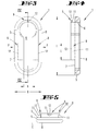
- Fig. 1
- eine perspektivische Ansicht von schräg oben des Sicherungsteils;
- Fig. 2
- eine Ansicht gemäß
Figur 1 , gesehen von schräg unten; - Fig. 3
- eine Draufsicht;
- Fig. 4
- ein Schnitt durch den Gegenstand gemäß
Figur 3 , geschnitten in der Ebene IV-IV inFigur 3 ; - Fig. 5
- eine Seitenansicht der Schmalseite;
- Fig. 6
- eine Unteransicht mit angedeutetem Schlüssel und Schlüsselloch; und
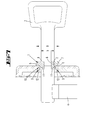
- Fig 7
- eine schematische Querschnittsansicht eines Schlosses mit Schlüsselloch, eingesetztem Bartschlüssel und Sicherungsteil.
- Dargestellt und beschrieben ist ein Sicherungsteil 1, das als einstückiges Kunststoff-Spritzteil dargestellt ist.
- Wie etwa aus
Figur 7 ersichtlich, kann das Sicherungsteil 1 in ein Schlüsselloch 2 eingesetzt werden derart, dass ein eingesetzter Bartschlüssel 3 nicht mehr entnommen werden kann. Dies zufolge einer so geringen Breite b, vergleiche etwaFiguren 1 ,3 und6 , des Sicherungsteils in einem Langlochabschnitt, dass ein Bart 4 des Bartschlüssels 3 diesen Bereich der Öffnung nicht durchsetzen kann. So ist in gleicher Weise eine Sicherung gegeben gegen Einsetzen eines Schlüssels, wenn das Sicherungsteil 1 in das Schlüsselloch 2 eingesetzt wird, solange sich noch kein Schlüssel, insbesondere Bartschlüssel 3, darin befindet, wie auch ein Sicherungsteil gegen Herausnehmen eines Schlüssels, wenn das Sicherungsteil erst nach in dem Schloss eingestecktem Schlüssel in das Schlüsselloch eingesteckt wird. - Das Sicherungsteil 1 ist im Wesentlichen allein durch ein Randteil 5 gegeben, das eine Öffnung 6 mit einer Öffnungsebene E begrenzt (siehe schematische Andeutung in
Figur 1 ). Weiter bildet das Randteil eine Auflagefläche 7 aus zur Auflage von außen auf einem Randbereich des Schlüsselloches 2. Die Öffnungsebene E ist in ihrer Ausrichtung bevorzugt entsprechend der Auflagefläche 7 ausgerichtet. Mit Bezug zu der Querschnittsdarstellung derFigur 4 kann die Öffnungsebene E abschließend mit der oberen Randkante 8 des Randteils 5 angesehen werden. - Unterseitig, d.h. einsteckseitig des Schlüsselloches 2 weist das Sicherungsteil beziehungsweise konkret das Randteil 5 zwei, gegenüberliegend ausgebildete Umgreifungsabschnitte 9 auf, zum Umgriff um den Randbereich 10 des Schlüsselloches 2.
- Ein Umgreifungsabschnitt 9 ist teilweise, nämlich zufolge seines Unterabschnittes 11, beabstandet, jedoch in unmittelbarer Überdeckung zu der Auflagefläche 7 ausgebildet, was etwa auch aus
Figur 2 ersichtlich ist. Das Randteil 5 ist in diesem Bereich U-förmig in einem Querschnitt gebildet, wobei der Unterabschnitt 11 wie auch die Auflagefläche 7 jeweils einen U-Schenkel darstellen. - Beim Ausführungsbeispiel und bevorzugt ist ersichtlich das Randteil 5 umlaufend geschlossen ausgebildet. Es stellt praktisch ein Ringteil dar, das langgestreckt verläuft.
- Eine Breite B des Sicherungsteils in der Draufsicht, vergleiche etwa
Figur 3 , entspricht etwa einem Drittel bis zwei Drittel, vorzugsweise der Hälfte, der Länge L (Figur 4 ). - Der Umgreifungsabschnitt 9 ist nur auf einer Teillänge L1, der Gesamtlänge L des Randteils, gesehen in Erstreckungsrichtung des Schlüsselloches, ausgebildet. Die Teillänge L1 kann etwa ein Zehntel bis fünf Zehntel der Gesamtlänge L betragen.
- Ungeachtet der schlüssellochartigen Kontur der Öffnung 6 ist eine Randkontur R (vergleiche
Figur 3 ) lediglich durch zwei Parallelen (Längsseiten) und zwei Halbkreise (Stirnseiten) gekennzeichnet. - Die Auflagefläche 7 ist als ebenflächiger Bereich ausgebildet.
- Insgesamt ist das Sicherungsteil, dargestellt praktisch allein durch das Randteil 5, als Kunststoff-Spritzteil gebildet, bevorzugt aus einem Hartwerkstoff.
- Zum Einbringen und Entfernen aus einem Schlüsselloch 2 ist das Sicherungsteil beziehungsweise konkret das Randteil 5 etwa mittig im Sinne der Pfeile P zusammenzudrücken, so dass die Unterabschnitte 11, die bevorzugt gegenüberliegend und weiter bevorzugt gleich lang sich erstreckend ausgebildet sind, außer Eingriff mit dem Randbereich des Schlüsselloches 2 kommen.
- Zum Einsetzen kann außenseitig an einem Untergreifabschnitt 9 eine Einführschräge 12 ausgebildet sein, so dass das Sicherungsteil durch Druck in Einsteckrichtung des Schlüssels, jedenfalls von Hand und relativ einfach in das Schlüsselloch eingesetzt werden kann. Aufgrund der bevorzugt gegebenen geringen Elastizität des Werkstoffes beziehungsweise der ausgebildeten Dicke des Kunststoffspritzteils ist jedoch gegeben, dass es nicht von Hand, jedenfalls nicht von einer Kinderhand, wieder werkzeuglos aus dem Schlüsselloch entfernt werden kann. Hierzu ist vielmehr in der Regel eine Zange erforderlich, um das Sicherungsteil dann in der beschriebenen Weise zusammenzudrücken und zu entfernen.
- Die Öffnung 6 ist ersichtlich bevorzugt ihrerseits wiederum schlüssellochartig gebildet, wobei der obere Rundbereich an den Schaft eines Schlüssels, insbesondere eines Bartschlüssels, angepasst ist, damit dieser auch bei eingesetztem Sicherungsteil 1 noch das Sicherungsteil 1 durchsetzen kann. Dagegen ist der untere langgestreckte Bereich mit einer solch geringen Breite b ausgebildet, dass der eingesetzte Schlüssel, dessen Bartabschnitt, hierdurch nicht mehr hindurchkann, so dass er in seiner im Schlüsselloch eingeführten Stellung gesichert ist oder eben nicht in das Schlüsselloch eingesetzt werden kann.
- Bevorzugt ist zusätzlich zu den den Längsseiten zugeordneten Untergreifabschnitten 9 noch ein weiterer Umgreifungsabschnitt 9 vorgesehen, welcher einer der Stirnseiten zugeordnet ist, nämlich bevorzugt der die runde Öffnungsvergrößerung zur Aufnahme des Schlüssellochs aufweisenden Stirnseite (anhand dieses Umgreifungsabschnittes 9 sind auch in
Figur 4 der Unterabschnitt 11 und die Einführschräge 12 erläutert). - Die Auflagefläche 7 ist in ihrer ebenen Erstreckung umlaufend mit unterschiedlicher Breite ausgebildet. Zur tatsächlichen Auflage, wie durch Schraffierung in
Figur 2 angedeutet, kommt aber umlaufend ein im Wesentlichen gleich breiter Bereich. Insbesondere ergibt sich schaftseitig bezüglich des eingesteckten Schlüssels (vergrößerter nahezu runder Öffnungsbereich der Öffnung 6) ausgehend von einem Umgreifungsabschnitt 9 ein Zwickelabschnitt 13 (sieheFigur 2 ) der ebenen Erstreckung, in welcher die Auflagefläche 7 gebildet ist, der im Einbauzustand teilweise zufolge der nicht deckungsgleichen Kontur K des Schlüsselloches, sieheFigur 6 , freiliegt. - Gleiches ergibt sich im gegenüberliegenden Endbereich bezüglich des Flächenabschnittes F, insofern auch gegenüberliegend.
- Zusätzlich zu einem oder zwei beziehungsweise drei Umgreifungsabschnitten 9 ist bei dem Sicherungsteil auch noch ein Eingriffskragen 14 ausgebildet, siehe insbesondere
Figur 2 . Der Eingriffskragen 14 ist bevorzugt nur dem im Einbauzustand dem Schaftbereich des Schlüssels zugeordneten Bereich der Öffnung 6 zugewandt und diese umgreifend, ausgehend von einem am Längsrand ausgebildeten Umgreifungsabschnitt 9, ausgebildet. - Der Eingriffskragen 14 greift nur senkrecht, in Schlüsseleinsteckrichtung beziehungsweise senkrecht zur Öffnungsebene E in das Schlüsselloch ein. Er untergreift nicht.
- Die vorstehenden Ausführungen dienen der Erläuterung der von der Anmeldung insgesamt erfassten Erfindungen, die den Stand der Technik zumindest durch die folgenden Merkmalskombinationen jeweils eigenständig weiterbilden, nämlich:
- Ein Sicherungsteil, das gekennzeichnet ist durch ein eine Öffnung 6 mit einer Öffnungsebene E begrenzendes Randteil 5, das eine Auflagefläche 7 ausbildet zur Auflage von außen auf einen Randbereich 10 des Schlüsselloches 2, wobei die Öffnungsebene E entsprechend der Auflagefläche 7 ausgerichtet ist, einen oder mehrere gegenüber der Auflagefläche 7 vorstehende, rückseitig an das Randteil 5 anschließende Umgreifungsabschnitte 9 zum Umgriff um den Randbereich 10, wobei ein Umgreifungsabschnitt 9 teilweise in beabstandeter, jedoch unmittelbarer Überdeckung zu der Auflagefläche 7 ausgebildet ist, so dass die Auflagefläche 7 in einem Querschnitt zusammen mit dem Randteil 5 U-förmig verlaufend gebildet ist.
- Ein Sicherungsteil, das dadurch gekennzeichnet ist, dass das Randteil 5 ringartig geschlossen umlaufend ausgebildet ist.
- Ein Sicherungsteil, das dadurch gekennzeichnet ist, dass ein Umgreifungsabschnitt 9 nur auf einer Teillänge des Randteils 5 ausgebildet ist.
- Ein Sicherungsteil, das dadurch gekennzeichnet ist, dass die Auflagefläche 7 durchgehend umlaufend ausgebildet ist.
- Ein Sicherungsteil, das dadurch gekennzeichnet ist, dass die Auflagefläche 7 ebenflächig ausgebildet ist.
- Ein Sicherungsteil, das dadurch gekennzeichnet ist, dass das Sicherungsteil 1 ein Kunststoff-Spritzteil ist.
- Ein Sicherungsteil, das dadurch gekennzeichnet ist, dass das Sicherungsteil aus einem Hartkunststoff besteht.
- Ein Sicherungsteil, das dadurch gekennzeichnet ist, dass das Sicherungsteil 1 zur Entfernung aus und/oder Einbringung in das Schlüsselloch 2 in Richtung zweier sich in Bezug auf die Öffnung 6 gegenüberliegender Abschnitte des Randteils 5 zusammenzudrücken ist.
- Ein Sicherungsteil, das dadurch gekennzeichnet ist, dass die Entfernung aus und/oder die Einbringung in das Schlüsselloch 2 mit der Handkraft eines Kindes nicht durchführbar ist.
- Ein Sicherungsteil, das dadurch gekennzeichnet ist, dass das Sicherungsteil 1 quer zu der Öffnungsebene E eine Abmessung aufweist, die ½- bis zu einem 2-Fachen, bevorzugt etwa dem 1,1-Fachen der Öffnungsbreite b entspricht.
- Ein Sicherungsteil, das dadurch gekennzeichnet ist, dass die Öffnungsebene E durch eine der Auflagefläche 7 gegenüberliegende Randkante 8 des Randteils (5) verläuft.
- Alle offenbarten Merkmale sind (für sich, aber auch in Kombination untereinander) erfindungswesentlich. In die Offenbarung der Anmeldung wird hiermit auch der Offenbarungsinhalt der zugehörigen/beigefügten Prioritätsunterlagen (Abschrift der Voranmeldung) vollinhaltlich mit einbezogen, auch zu dem Zweck, Merkmale dieser Unterlagen in Ansprüche vorliegender Anmeldung mit aufzunehmen. Die Unteransprüche charakterisieren mit ihren Merkmalen eigenständige erfinderische Weiterbildungen des Standes der Technik, insbesondere um auf Basis dieser Ansprüche Teilanmeldungen vorzunehmen.
Bezugszeichenliste: 1 Sicherungsteil B Breite 2 Schlüsseloch E Öffnungsebene 3 Bartschlüssel F Flächenabschnitt 4 Bart K Kontur 5 Randteil L Gesamtlänge 6 Öffnung L1 Teillänge 7 Auflagefläche R Randkante 8 Randkante 9 Umgreifungsabschnitt b Breite 10 Randbereich 11 Unterabschnitt 12 Einführschräge 13 Zwickelabschnitt 14 Eingriffskragen
Claims (12)
- In ein Schlüsselloch (2) eines Schlosses für einen Bartschlüssel (3) einsetzbares einteiliges, sich am Schlüsselloch (2) selbst halterndes Sicherungsteil (1), gekennzeichnet durch ein eine Öffnung (6) mit einer Öffnungsebene (E) begrenzendes Randteil (5), das eine Auflagefläche (7) ausbildet zur Auflage von außen auf einen Randbereich (10) des Schlüsselloches (2), wobei die Öffnungsebene (E) entsprechend der Auflagefläche (7) ausgerichtet ist, einen oder mehrere gegenüber der Auflagefläche (7) vorstehende, rückseitig an das Randteil (5) anschließende Umgreifungsabschnitte (9) zum Umgriff um den Randbereich (10), wobei ein Umgreifungsabschnitt (9) teilweise in beabstandeter, jedoch unmittelbarer Überdeckung zu der Auflagefläche (7) ausgebildet ist, so dass die Auflagefläche (7) in einem Querschnitt zusammen mit dem Randteil (5) U-förmig verlaufend gebildet ist.
- Sicherungsteil nach Anspruch 1, dadurch gekennzeichnet, dass das Randteil (5) ringartig geschlossen umlaufend ausgebildet ist.
- Sicherungsteil nach einem der vorhergehenden Ansprüche, dadurch gekennzeichnet, dass ein Umgreifungsabschnitt (9) nur auf einer Teillänge des Randteils (5) ausgebildet ist.
- Sicherungsteil nach einem der vorhergehenden Ansprüche, dadurch gekennzeichnet, dass die Auflagefläche (7) durchgehend umlaufend ausgebildet ist.
- Sicherungsteil nach einem der vorhergehenden Ansprüche, dadurch gekennzeichnet, dass die Auflagefläche (7) ebenflächig ausgebildet ist.
- Sicherungsteil nach einem der vorhergehenden Ansprüche, dadurch gekennzeichnet, dass das Sicherungsteil (1) ein Kunststoff-Spritzteil ist.
- Sicherungsteil nach Anspruch 6, dadurch gekennzeichnet, dass das Sicherungsteil aus einem Hartkunststoff besteht.
- Sicherungsteil nach einem der vorhergehenden Ansprüche, dadurch gekennzeichnet, dass das Sicherungsteil (1) zur Entfernung aus und/oder Einbringung in das Schlüsselloch (2) in Richtung zweier sich in Bezug auf die Öffnung (6) gegenüberliegender Abschnitte des Randteils (5) zusammenzudrücken ist.
- Sicherungsteil nach einem der vorhergehenden Ansprüche, dadurch gekennzeichnet, dass die Entfernung aus und/oder die Einbringung in das Schlüsselloch (2) mit der Handkraft eines Kindes nicht durchführbar ist.
- Sicherungsteil nach einem der vorhergehenden Ansprüche, dadurch gekennzeichnet, dass das Sicherungsteil (1) quer zu der Öffnungsebene (E) eine Abmessung aufweist, die ½- bis zu einem 2-Fachen, bevorzugt etwa dem 1,1-Fachen der Öffnungsbreite (b) entspricht.
- Sicherungsteil nach einem der vorhergehenden Ansprüche, dadurch gekennzeichnet, dass die Öffnungsebene (E) durch eine der Auflagefläche (7) gegenüberliegende Randkante (8) des Randteils (5) verläuft.
- Sicherungsteil, gekennzeichnet durch eines oder mehrere der kennzeichnenden Merkmale eines der vorhergehenden Ansprüche.
Applications Claiming Priority (1)
| Application Number | Priority Date | Filing Date | Title |
|---|---|---|---|
| DE102013106568.6A DE102013106568A1 (de) | 2013-06-24 | 2013-06-24 | Sicherungsteil |
Publications (3)
| Publication Number | Publication Date |
|---|---|
| EP2818612A2 true EP2818612A2 (de) | 2014-12-31 |
| EP2818612A3 EP2818612A3 (de) | 2016-04-06 |
| EP2818612B1 EP2818612B1 (de) | 2018-12-26 |
Family
ID=50942044
Family Applications (1)
| Application Number | Title | Priority Date | Filing Date |
|---|---|---|---|
| EP14171277.8A Active EP2818612B1 (de) | 2013-06-24 | 2014-06-05 | Sicherungsteil |
Country Status (2)
| Country | Link |
|---|---|
| EP (1) | EP2818612B1 (de) |
| DE (1) | DE102013106568A1 (de) |
Citations (1)
| Publication number | Priority date | Publication date | Assignee | Title |
|---|---|---|---|---|
| DE2658154A1 (de) | 1976-12-22 | 1978-07-06 | Precupa Gmbh Werkzeug Und Masc | Schluesselsicherung |
Family Cites Families (3)
| Publication number | Priority date | Publication date | Assignee | Title |
|---|---|---|---|---|
| DE2205758A1 (de) * | 1972-02-08 | 1973-08-09 | Hermann Schmidt | Schluesselsperrer |
| DE20005634U1 (de) * | 2000-03-25 | 2000-06-29 | Grothklags, Hartmut, 33818 Leopoldshöhe | Türschlüsselhalter, zum Halten vom Schlüssel, der sich im Schloss befindet und sich an der Rückseite der Blende verhakt |
| DE10357995A1 (de) * | 2003-12-11 | 2005-07-14 | Egon Kupferschmid | Abdeckkappe für ein Schlüsselloch |
-
2013
- 2013-06-24 DE DE102013106568.6A patent/DE102013106568A1/de not_active Withdrawn
-
2014
- 2014-06-05 EP EP14171277.8A patent/EP2818612B1/de active Active
Patent Citations (1)
| Publication number | Priority date | Publication date | Assignee | Title |
|---|---|---|---|---|
| DE2658154A1 (de) | 1976-12-22 | 1978-07-06 | Precupa Gmbh Werkzeug Und Masc | Schluesselsicherung |
Also Published As
| Publication number | Publication date |
|---|---|
| EP2818612B1 (de) | 2018-12-26 |
| EP2818612A3 (de) | 2016-04-06 |
| DE102013106568A1 (de) | 2014-12-24 |
Similar Documents
| Publication | Publication Date | Title |
|---|---|---|
| DE102011000787B4 (de) | Zusammenfassung von Schaltschrankschlüsseln | |
| EP3113908B1 (de) | Zange | |
| AT517169B1 (de) | Lageranordnung | |
| EP3138990A1 (de) | Insektenschutzvorrichtung mit adapterprofilleiste | |
| DE102010004277A1 (de) | Trampolin | |
| DE202012002687U1 (de) | Verbinder | |
| EP3242985B1 (de) | Motorschloss | |
| DE102013103947A1 (de) | Verbindung zwischen Profilelementen einer Rahmenkonstruktion | |
| DE20005661U1 (de) | Elastische Kniegelenkbandage | |
| EP2818612A2 (de) | Sicherungsteil | |
| DE102007024250A1 (de) | Auszugsprofil für Fensterblende | |
| DE29603389U1 (de) | Schnellverschluß | |
| EP0485936B1 (de) | Stangenverschluss mit lösbarer Stangenverbindung | |
| DE102018203781B4 (de) | Stiftzylinder-Schlüssel-System und Schlüssel dafür | |
| DE102015000490A1 (de) | Befestigungselement | |
| DE202015102362U1 (de) | Element zur Einfassung von Beeten und Grünlandflächen | |
| DE19903836C2 (de) | Abdeckung für Licht- und/oder Lüftungsschächte sowie Profilstab hierfür | |
| DE202010017396U1 (de) | Trampolin | |
| DE202007008187U1 (de) | Auszugsprofil für Fensterblende | |
| EP3722550B1 (de) | Dichtung mit mehreren segmenten umfassend je eine absenkbare dichtleiste | |
| DE102014115060B4 (de) | Verbindungseinrichtung | |
| DE102016001091B3 (de) | Trainingsgerät für Sportübungen | |
| DE102009057786B4 (de) | Doppelschließzylinder | |
| DE202021102434U1 (de) | Hebevorrichtung | |
| DE29923660U1 (de) | Abdeckung für Licht- und/oder Lüftungsschächte sowie Profilstab hierfür |
Legal Events
| Date | Code | Title | Description |
|---|---|---|---|
| PUAI | Public reference made under article 153(3) epc to a published international application that has entered the european phase |
Free format text: ORIGINAL CODE: 0009012 |
|
| 17P | Request for examination filed |
Effective date: 20140605 |
|
| AK | Designated contracting states |
Kind code of ref document: A2 Designated state(s): AL AT BE BG CH CY CZ DE DK EE ES FI FR GB GR HR HU IE IS IT LI LT LU LV MC MK MT NL NO PL PT RO RS SE SI SK SM TR |
|
| AX | Request for extension of the european patent |
Extension state: BA ME |
|
| PUAL | Search report despatched |
Free format text: ORIGINAL CODE: 0009013 |
|
| AK | Designated contracting states |
Kind code of ref document: A3 Designated state(s): AL AT BE BG CH CY CZ DE DK EE ES FI FR GB GR HR HU IE IS IT LI LT LU LV MC MK MT NL NO PL PT RO RS SE SI SK SM TR |
|
| AX | Request for extension of the european patent |
Extension state: BA ME |
|
| RIC1 | Information provided on ipc code assigned before grant |
Ipc: E05B 11/00 20060101ALI20160302BHEP Ipc: E05B 17/14 20060101AFI20160302BHEP |
|
| R17P | Request for examination filed (corrected) |
Effective date: 20160601 |
|
| RBV | Designated contracting states (corrected) |
Designated state(s): AL AT BE BG CH CY CZ DE DK EE ES FI FR GB GR HR HU IE IS IT LI LT LU LV MC MK MT NL NO PL PT RO RS SE SI SK SM TR |
|
| GRAP | Despatch of communication of intention to grant a patent |
Free format text: ORIGINAL CODE: EPIDOSNIGR1 |
|
| STAA | Information on the status of an ep patent application or granted ep patent |
Free format text: STATUS: GRANT OF PATENT IS INTENDED |
|
| INTG | Intention to grant announced |
Effective date: 20180601 |
|
| GRAS | Grant fee paid |
Free format text: ORIGINAL CODE: EPIDOSNIGR3 |
|
| GRAA | (expected) grant |
Free format text: ORIGINAL CODE: 0009210 |
|
| STAA | Information on the status of an ep patent application or granted ep patent |
Free format text: STATUS: THE PATENT HAS BEEN GRANTED |
|
| AK | Designated contracting states |
Kind code of ref document: B1 Designated state(s): AL AT BE BG CH CY CZ DE DK EE ES FI FR GB GR HR HU IE IS IT LI LT LU LV MC MK MT NL NO PL PT RO RS SE SI SK SM TR |
|
| REG | Reference to a national code |
Ref country code: GB Ref legal event code: FG4D Free format text: NOT ENGLISH |
|
| REG | Reference to a national code |
Ref country code: CH Ref legal event code: EP |
|
| REG | Reference to a national code |
Ref country code: AT Ref legal event code: REF Ref document number: 1081621 Country of ref document: AT Kind code of ref document: T Effective date: 20190115 |
|
| REG | Reference to a national code |
Ref country code: DE Ref legal event code: R096 Ref document number: 502014010434 Country of ref document: DE |
|
| REG | Reference to a national code |
Ref country code: IE Ref legal event code: FG4D Free format text: LANGUAGE OF EP DOCUMENT: GERMAN |
|
| PG25 | Lapsed in a contracting state [announced via postgrant information from national office to epo] |
Ref country code: FI Free format text: LAPSE BECAUSE OF FAILURE TO SUBMIT A TRANSLATION OF THE DESCRIPTION OR TO PAY THE FEE WITHIN THE PRESCRIBED TIME-LIMIT Effective date: 20181226 Ref country code: LV Free format text: LAPSE BECAUSE OF FAILURE TO SUBMIT A TRANSLATION OF THE DESCRIPTION OR TO PAY THE FEE WITHIN THE PRESCRIBED TIME-LIMIT Effective date: 20181226 Ref country code: HR Free format text: LAPSE BECAUSE OF FAILURE TO SUBMIT A TRANSLATION OF THE DESCRIPTION OR TO PAY THE FEE WITHIN THE PRESCRIBED TIME-LIMIT Effective date: 20181226 Ref country code: NO Free format text: LAPSE BECAUSE OF FAILURE TO SUBMIT A TRANSLATION OF THE DESCRIPTION OR TO PAY THE FEE WITHIN THE PRESCRIBED TIME-LIMIT Effective date: 20190326 Ref country code: BG Free format text: LAPSE BECAUSE OF FAILURE TO SUBMIT A TRANSLATION OF THE DESCRIPTION OR TO PAY THE FEE WITHIN THE PRESCRIBED TIME-LIMIT Effective date: 20190326 Ref country code: LT Free format text: LAPSE BECAUSE OF FAILURE TO SUBMIT A TRANSLATION OF THE DESCRIPTION OR TO PAY THE FEE WITHIN THE PRESCRIBED TIME-LIMIT Effective date: 20181226 |
|
| REG | Reference to a national code |
Ref country code: NL Ref legal event code: MP Effective date: 20181226 |
|
| REG | Reference to a national code |
Ref country code: LT Ref legal event code: MG4D |
|
| PG25 | Lapsed in a contracting state [announced via postgrant information from national office to epo] |
Ref country code: AL Free format text: LAPSE BECAUSE OF FAILURE TO SUBMIT A TRANSLATION OF THE DESCRIPTION OR TO PAY THE FEE WITHIN THE PRESCRIBED TIME-LIMIT Effective date: 20181226 Ref country code: RS Free format text: LAPSE BECAUSE OF FAILURE TO SUBMIT A TRANSLATION OF THE DESCRIPTION OR TO PAY THE FEE WITHIN THE PRESCRIBED TIME-LIMIT Effective date: 20181226 Ref country code: GR Free format text: LAPSE BECAUSE OF FAILURE TO SUBMIT A TRANSLATION OF THE DESCRIPTION OR TO PAY THE FEE WITHIN THE PRESCRIBED TIME-LIMIT Effective date: 20190327 Ref country code: SE Free format text: LAPSE BECAUSE OF FAILURE TO SUBMIT A TRANSLATION OF THE DESCRIPTION OR TO PAY THE FEE WITHIN THE PRESCRIBED TIME-LIMIT Effective date: 20181226 |
|
| PG25 | Lapsed in a contracting state [announced via postgrant information from national office to epo] |
Ref country code: NL Free format text: LAPSE BECAUSE OF FAILURE TO SUBMIT A TRANSLATION OF THE DESCRIPTION OR TO PAY THE FEE WITHIN THE PRESCRIBED TIME-LIMIT Effective date: 20181226 |
|
| PG25 | Lapsed in a contracting state [announced via postgrant information from national office to epo] |
Ref country code: PT Free format text: LAPSE BECAUSE OF FAILURE TO SUBMIT A TRANSLATION OF THE DESCRIPTION OR TO PAY THE FEE WITHIN THE PRESCRIBED TIME-LIMIT Effective date: 20190426 Ref country code: CZ Free format text: LAPSE BECAUSE OF FAILURE TO SUBMIT A TRANSLATION OF THE DESCRIPTION OR TO PAY THE FEE WITHIN THE PRESCRIBED TIME-LIMIT Effective date: 20181226 Ref country code: ES Free format text: LAPSE BECAUSE OF FAILURE TO SUBMIT A TRANSLATION OF THE DESCRIPTION OR TO PAY THE FEE WITHIN THE PRESCRIBED TIME-LIMIT Effective date: 20181226 Ref country code: IT Free format text: LAPSE BECAUSE OF FAILURE TO SUBMIT A TRANSLATION OF THE DESCRIPTION OR TO PAY THE FEE WITHIN THE PRESCRIBED TIME-LIMIT Effective date: 20181226 Ref country code: PL Free format text: LAPSE BECAUSE OF FAILURE TO SUBMIT A TRANSLATION OF THE DESCRIPTION OR TO PAY THE FEE WITHIN THE PRESCRIBED TIME-LIMIT Effective date: 20181226 |
|
| PG25 | Lapsed in a contracting state [announced via postgrant information from national office to epo] |
Ref country code: SM Free format text: LAPSE BECAUSE OF FAILURE TO SUBMIT A TRANSLATION OF THE DESCRIPTION OR TO PAY THE FEE WITHIN THE PRESCRIBED TIME-LIMIT Effective date: 20181226 Ref country code: EE Free format text: LAPSE BECAUSE OF FAILURE TO SUBMIT A TRANSLATION OF THE DESCRIPTION OR TO PAY THE FEE WITHIN THE PRESCRIBED TIME-LIMIT Effective date: 20181226 Ref country code: SK Free format text: LAPSE BECAUSE OF FAILURE TO SUBMIT A TRANSLATION OF THE DESCRIPTION OR TO PAY THE FEE WITHIN THE PRESCRIBED TIME-LIMIT Effective date: 20181226 Ref country code: RO Free format text: LAPSE BECAUSE OF FAILURE TO SUBMIT A TRANSLATION OF THE DESCRIPTION OR TO PAY THE FEE WITHIN THE PRESCRIBED TIME-LIMIT Effective date: 20181226 Ref country code: IS Free format text: LAPSE BECAUSE OF FAILURE TO SUBMIT A TRANSLATION OF THE DESCRIPTION OR TO PAY THE FEE WITHIN THE PRESCRIBED TIME-LIMIT Effective date: 20190426 |
|
| REG | Reference to a national code |
Ref country code: DE Ref legal event code: R097 Ref document number: 502014010434 Country of ref document: DE |
|
| PG25 | Lapsed in a contracting state [announced via postgrant information from national office to epo] |
Ref country code: DK Free format text: LAPSE BECAUSE OF FAILURE TO SUBMIT A TRANSLATION OF THE DESCRIPTION OR TO PAY THE FEE WITHIN THE PRESCRIBED TIME-LIMIT Effective date: 20181226 |
|
| PLBE | No opposition filed within time limit |
Free format text: ORIGINAL CODE: 0009261 |
|
| STAA | Information on the status of an ep patent application or granted ep patent |
Free format text: STATUS: NO OPPOSITION FILED WITHIN TIME LIMIT |
|
| 26N | No opposition filed |
Effective date: 20190927 |
|
| PG25 | Lapsed in a contracting state [announced via postgrant information from national office to epo] |
Ref country code: MC Free format text: LAPSE BECAUSE OF FAILURE TO SUBMIT A TRANSLATION OF THE DESCRIPTION OR TO PAY THE FEE WITHIN THE PRESCRIBED TIME-LIMIT Effective date: 20181226 |
|
| GBPC | Gb: european patent ceased through non-payment of renewal fee |
Effective date: 20190605 |
|
| PG25 | Lapsed in a contracting state [announced via postgrant information from national office to epo] |
Ref country code: SI Free format text: LAPSE BECAUSE OF FAILURE TO SUBMIT A TRANSLATION OF THE DESCRIPTION OR TO PAY THE FEE WITHIN THE PRESCRIBED TIME-LIMIT Effective date: 20181226 |
|
| REG | Reference to a national code |
Ref country code: BE Ref legal event code: MM Effective date: 20190630 |
|
| PG25 | Lapsed in a contracting state [announced via postgrant information from national office to epo] |
Ref country code: TR Free format text: LAPSE BECAUSE OF FAILURE TO SUBMIT A TRANSLATION OF THE DESCRIPTION OR TO PAY THE FEE WITHIN THE PRESCRIBED TIME-LIMIT Effective date: 20181226 |
|
| PG25 | Lapsed in a contracting state [announced via postgrant information from national office to epo] |
Ref country code: GB Free format text: LAPSE BECAUSE OF NON-PAYMENT OF DUE FEES Effective date: 20190605 Ref country code: IE Free format text: LAPSE BECAUSE OF NON-PAYMENT OF DUE FEES Effective date: 20190605 |
|
| PG25 | Lapsed in a contracting state [announced via postgrant information from national office to epo] |
Ref country code: LU Free format text: LAPSE BECAUSE OF NON-PAYMENT OF DUE FEES Effective date: 20190605 Ref country code: BE Free format text: LAPSE BECAUSE OF NON-PAYMENT OF DUE FEES Effective date: 20190630 |
|
| PG25 | Lapsed in a contracting state [announced via postgrant information from national office to epo] |
Ref country code: FR Free format text: LAPSE BECAUSE OF NON-PAYMENT OF DUE FEES Effective date: 20190630 |
|
| PG25 | Lapsed in a contracting state [announced via postgrant information from national office to epo] |
Ref country code: CY Free format text: LAPSE BECAUSE OF FAILURE TO SUBMIT A TRANSLATION OF THE DESCRIPTION OR TO PAY THE FEE WITHIN THE PRESCRIBED TIME-LIMIT Effective date: 20181226 |
|
| PG25 | Lapsed in a contracting state [announced via postgrant information from national office to epo] |
Ref country code: HU Free format text: LAPSE BECAUSE OF FAILURE TO SUBMIT A TRANSLATION OF THE DESCRIPTION OR TO PAY THE FEE WITHIN THE PRESCRIBED TIME-LIMIT; INVALID AB INITIO Effective date: 20140605 Ref country code: MT Free format text: LAPSE BECAUSE OF FAILURE TO SUBMIT A TRANSLATION OF THE DESCRIPTION OR TO PAY THE FEE WITHIN THE PRESCRIBED TIME-LIMIT Effective date: 20181226 |
|
| PG25 | Lapsed in a contracting state [announced via postgrant information from national office to epo] |
Ref country code: MK Free format text: LAPSE BECAUSE OF FAILURE TO SUBMIT A TRANSLATION OF THE DESCRIPTION OR TO PAY THE FEE WITHIN THE PRESCRIBED TIME-LIMIT Effective date: 20181226 |
|
| PGFP | Annual fee paid to national office [announced via postgrant information from national office to epo] |
Ref country code: DE Payment date: 20220621 Year of fee payment: 9 |
|
| PGFP | Annual fee paid to national office [announced via postgrant information from national office to epo] |
Ref country code: AT Payment date: 20220621 Year of fee payment: 9 |
|
| PGFP | Annual fee paid to national office [announced via postgrant information from national office to epo] |
Ref country code: CH Payment date: 20220622 Year of fee payment: 9 |
|
| REG | Reference to a national code |
Ref country code: DE Ref legal event code: R119 Ref document number: 502014010434 Country of ref document: DE |
|
| REG | Reference to a national code |
Ref country code: CH Ref legal event code: PL |
|
| REG | Reference to a national code |
Ref country code: AT Ref legal event code: MM01 Ref document number: 1081621 Country of ref document: AT Kind code of ref document: T Effective date: 20230605 |
|
| PG25 | Lapsed in a contracting state [announced via postgrant information from national office to epo] |
Ref country code: AT Free format text: LAPSE BECAUSE OF NON-PAYMENT OF DUE FEES Effective date: 20230605 |
|
| PG25 | Lapsed in a contracting state [announced via postgrant information from national office to epo] |
Ref country code: DE Free format text: LAPSE BECAUSE OF NON-PAYMENT OF DUE FEES Effective date: 20240103 Ref country code: AT Free format text: LAPSE BECAUSE OF NON-PAYMENT OF DUE FEES Effective date: 20230605 Ref country code: CH Free format text: LAPSE BECAUSE OF NON-PAYMENT OF DUE FEES Effective date: 20230630 |