EP2817543B1 - Soupape à diaphragme - Google Patents
Soupape à diaphragme Download PDFInfo
- Publication number
- EP2817543B1 EP2817543B1 EP13710295.0A EP13710295A EP2817543B1 EP 2817543 B1 EP2817543 B1 EP 2817543B1 EP 13710295 A EP13710295 A EP 13710295A EP 2817543 B1 EP2817543 B1 EP 2817543B1
- Authority
- EP
- European Patent Office
- Prior art keywords
- diaphragm
- valve
- sealing
- membrane
- section
- Prior art date
- Legal status (The legal status is an assumption and is not a legal conclusion. Google has not performed a legal analysis and makes no representation as to the accuracy of the status listed.)
- Active
Links
Images


Classifications
-
- F—MECHANICAL ENGINEERING; LIGHTING; HEATING; WEAPONS; BLASTING
- F16—ENGINEERING ELEMENTS AND UNITS; GENERAL MEASURES FOR PRODUCING AND MAINTAINING EFFECTIVE FUNCTIONING OF MACHINES OR INSTALLATIONS; THERMAL INSULATION IN GENERAL
- F16K—VALVES; TAPS; COCKS; ACTUATING-FLOATS; DEVICES FOR VENTING OR AERATING
- F16K7/00—Diaphragm valves or cut-off apparatus, e.g. with a member deformed, but not moved bodily, to close the passage ; Pinch valves
- F16K7/12—Diaphragm valves or cut-off apparatus, e.g. with a member deformed, but not moved bodily, to close the passage ; Pinch valves with flat, dished, or bowl-shaped diaphragm
- F16K7/126—Diaphragm valves or cut-off apparatus, e.g. with a member deformed, but not moved bodily, to close the passage ; Pinch valves with flat, dished, or bowl-shaped diaphragm the seat being formed on a rib perpendicular to the fluid line
-
- F—MECHANICAL ENGINEERING; LIGHTING; HEATING; WEAPONS; BLASTING
- F16—ENGINEERING ELEMENTS AND UNITS; GENERAL MEASURES FOR PRODUCING AND MAINTAINING EFFECTIVE FUNCTIONING OF MACHINES OR INSTALLATIONS; THERMAL INSULATION IN GENERAL
- F16K—VALVES; TAPS; COCKS; ACTUATING-FLOATS; DEVICES FOR VENTING OR AERATING
- F16K31/00—Actuating devices; Operating means; Releasing devices
- F16K31/02—Actuating devices; Operating means; Releasing devices electric; magnetic
- F16K31/06—Actuating devices; Operating means; Releasing devices electric; magnetic using a magnet, e.g. diaphragm valves, cutting off by means of a liquid
- F16K31/0603—Multiple-way valves
- F16K31/0641—Multiple-way valves the valve member being a diaphragm
-
- F—MECHANICAL ENGINEERING; LIGHTING; HEATING; WEAPONS; BLASTING
- F16—ENGINEERING ELEMENTS AND UNITS; GENERAL MEASURES FOR PRODUCING AND MAINTAINING EFFECTIVE FUNCTIONING OF MACHINES OR INSTALLATIONS; THERMAL INSULATION IN GENERAL
- F16K—VALVES; TAPS; COCKS; ACTUATING-FLOATS; DEVICES FOR VENTING OR AERATING
- F16K31/00—Actuating devices; Operating means; Releasing devices
- F16K31/02—Actuating devices; Operating means; Releasing devices electric; magnetic
- F16K31/06—Actuating devices; Operating means; Releasing devices electric; magnetic using a magnet, e.g. diaphragm valves, cutting off by means of a liquid
- F16K31/0644—One-way valve
- F16K31/0672—One-way valve the valve member being a diaphragm
-
- F—MECHANICAL ENGINEERING; LIGHTING; HEATING; WEAPONS; BLASTING
- F16—ENGINEERING ELEMENTS AND UNITS; GENERAL MEASURES FOR PRODUCING AND MAINTAINING EFFECTIVE FUNCTIONING OF MACHINES OR INSTALLATIONS; THERMAL INSULATION IN GENERAL
- F16K—VALVES; TAPS; COCKS; ACTUATING-FLOATS; DEVICES FOR VENTING OR AERATING
- F16K31/00—Actuating devices; Operating means; Releasing devices
- F16K31/02—Actuating devices; Operating means; Releasing devices electric; magnetic
- F16K31/06—Actuating devices; Operating means; Releasing devices electric; magnetic using a magnet, e.g. diaphragm valves, cutting off by means of a liquid
- F16K31/10—Actuating devices; Operating means; Releasing devices electric; magnetic using a magnet, e.g. diaphragm valves, cutting off by means of a liquid with additional mechanism between armature and closure member
-
- F—MECHANICAL ENGINEERING; LIGHTING; HEATING; WEAPONS; BLASTING
- F16—ENGINEERING ELEMENTS AND UNITS; GENERAL MEASURES FOR PRODUCING AND MAINTAINING EFFECTIVE FUNCTIONING OF MACHINES OR INSTALLATIONS; THERMAL INSULATION IN GENERAL
- F16K—VALVES; TAPS; COCKS; ACTUATING-FLOATS; DEVICES FOR VENTING OR AERATING
- F16K7/00—Diaphragm valves or cut-off apparatus, e.g. with a member deformed, but not moved bodily, to close the passage ; Pinch valves
- F16K7/12—Diaphragm valves or cut-off apparatus, e.g. with a member deformed, but not moved bodily, to close the passage ; Pinch valves with flat, dished, or bowl-shaped diaphragm
- F16K7/14—Diaphragm valves or cut-off apparatus, e.g. with a member deformed, but not moved bodily, to close the passage ; Pinch valves with flat, dished, or bowl-shaped diaphragm arranged to be deformed against a flat seat
Definitions
- the invention relates to a diaphragm valve, with a valve housing and at least one movable valve member, wherein the valve member has a movable under execution of a switching movement relative to the valve housing diaphragm carrier and a common with the valve housing a valve chamber limiting flexible sealing membrane, wherein the sealing membrane at its outer Fixed edge region is sealed to the valve housing and has a fixed thereto at a distance to the membrane carrier and its Umschaltschul mit mannerden attachment membrane portion, wherein in the valve chamber, a sealing membrane facing valve seat is arranged, to a at least partially facing from one of the valve chamber base of Membranismes supported sealing portion of the sealing membrane is sealingly pressed to separate at least two in the valve chamber opening fluid channels from each other, wherein the diaphragm valve is a membrane contains body which is functionally divided into two sealing membranes, which are each connected to its own membrane carrier and which can cooperate with its own valve seat, wherein the two membrane carriers are formed plunger-like and parallel linearly movable under execution of
- One from the EP 1 722 137 A2 known diaphragm valve includes at least one arranged in a valve housing valve member consisting of a valve chamber delimiting a sealing membrane and a sealing membrane supporting, designed in the manner of a plunger membrane carrier, which is linearly movable relative to the valve housing.
- the membrane carrier supports with its base an annular sealing portion of the sealing membrane, which can be brought into abutment against an annular valve seat arranged in the valve chamber in order to separate two fluid channels opening into the valve chamber from each other.
- the sealing portion is part of a diaphragm portion fixed to the valve member, which is referred to as a fastening membrane portion and which participates in the switching movement of the membrane carrier. At its outer edge region, the sealing membrane is clamped under sealing on the valve housing.
- a disadvantage of the known diaphragm valve is the fact that the sealing membrane is temporarily greatly expanded when switching the valve member and thus subject to high stress, which can adversely affect the life.
- a diaphragm valve of similar construction which has two valve members, each containing a plunger-like membrane carrier and a membrane carrier mounted on the, with a valve seat cooperating sealing membrane, wherein the sealing membranes are integrally combined in a membrane body.
- the DE 60017310 T2 discloses a diaphragm valve with a valve housing having a sealing membrane-bearing, pivotally mounted on a valve housing membrane carrier.
- the membrane carrier supports with its base two sealing portions of the sealing membrane, which can cooperate with each with its own valve seat to total three selectively connect to each other or separate from each other in a valve chamber opening fluid channels.
- the switching position of the valve carrier can be predetermined by drive means which act on the membrane carrier and cause its pivoting switching movement. Also in this diaphragm valve, the problem arises that the flexible sealing membrane is greatly stretched, especially in the membrane section extending between the membrane carrier and the fixed edge region, and is exposed to high tensile stresses.
- One from the DE 7324333 U known diaphragm valve has a sealing chamber closing a valve chamber, which is held by a stiffening plate. Protruding from the sealing membrane projections pass through the stiffening plate and are based on an independent of the sealing membrane in a valve housing pivotally mounted actuator. At the pivotal movement of the membrane carrier, the sealing membrane does not participate, which affects the available valve lift.
- the FR 2795798 A discloses a diaphragm valve whose valve member has a pivotable membrane carrier and a diaphragm body attached to the membrane carrier, wherein the membrane body forms a sealing membrane, the edge in the Valve housing is fixed under seal.
- a membrane section of the sealing membrane framing the membrane carrier is subject to a high tensile stress, which can impair the service life.
- the sealing portion is at least partially part of a loose membrane portion of the sealing membrane, which, without being attached to the membrane carrier, starting from the mounting diaphragm section to the fixed to the valve housing outer Edge region of the sealing membrane extends so that it lifts off from the base surface of the membrane carrier, when the membrane carrier moves away during its switching movement of the valve seat.
- a sealing section of the sealing membrane is further pressed by the membrane membrane-carrying membrane carrier under sealing against an associated valve seat.
- the sealing membrane is subject to only a slight elongation even when the sealing portion is lifted by appropriate switching movement of the membrane carrier from the associated valve seat.
- the reason for this is that at least a portion of the sealing portion belongs to a membrane portion of the sealing membrane which extends between the attachment membrane portion and the valve housing fixed to the outer edge region of the sealing membrane in the membrane carrier not fixed manner and therefore is able to move away from the Base surface of the membrane carrier to solve when the membrane carrier moves away during its switching movement of the associated valve seat.
- This unfixed membrane section is referred to as a loose membrane section.
- the sealing portion is thus mechanically supportable for fluid-tight interaction with the valve seat through the membrane carrier, at least a portion of the sealing portion has the ability to withdraw from the previously still resting on him base of the membrane support or detach from this base, if the membrane support for the purpose of Releasing a fluid connection in the sense of being moved away from the valve seat.
- a behavioral pattern can result here, which can be achieved by folding away or by folding away the loose membrane section could describe from the membrane carrier.
- a wedge-shaped widening gap between the loose membrane section and the membrane carrier can open up towards the edge of the base surface. Since the sealing membrane in the liftable from the membrane carrier areas is not forced to join the switching movement of the membrane carrier in full, it is subject to a relatively low strain.
- the diaphragm valve is equipped with electrically actuatable drive means which serve to actuate the valve member and which make it possible to drive the membrane carrier as needed to their switching movement and also to hold in the desired position.
- drive means preferably contain at least one electromagnetic device and preferably also at least one return spring device which predetermines a desired basic position.
- the sealing membrane is fastened with its attachment membrane portion in the region of the base surface of the membrane carrier such that there is a radial distance between this attachment membrane portion and the outline of the base area of the membrane carrier around the attachment membrane portion.
- the area of the sealing membrane located between the fastening membrane section and the outline of the base area is a component of the loose membrane section.
- the attachment membrane section is arranged in particular centrally in the region of the base surface. Particularly useful is an embodiment in which the loose membrane portion surrounds the attachment membrane portion in an area which is upstream of the base, all around. In this way, in particular results in an annular region of the loose membrane portion which is movable in the switching movement of the membrane carrier relative to the membrane carrier in order not to be forced to follow the switching movement of the membrane carrier in full and thereby exposed to a high strain load.
- valve seat of the diaphragm valve is formed annularly closed in itself, so that it framed the channel mouth of a fluid channel.
- a ring-shaped sealing portion of the sealing membrane on the valve seat is also a ring-shaped sealing portion of the sealing membrane on the valve seat.
- annular sealing portion at least a portion is formed as part of the loose membrane portion, so that it can lift off from the membrane carrier, when selbiger is moved away to release the fluid channel of the valve seat.
- the sealing membrane is formed so that a cooperating with an annular valve seat annular sealing portion in its entirety is a part of the loose membrane portion, so that it can lift off completely from the base of the membrane carrier, when the membrane carrier in the switching movement away from the valve seat , Basically, however, a design is possible in which the cooperating with the valve seat sealing portion is partially a part of the attachment membrane portion and only partially a part of the loose membrane portion.
- the sealing portion is expediently completely within the outer contour of the base of the membrane carrier.
- the valve seat is web-like and extends between two opposite lateral wall sections of the valve chamber, that it subdivides this valve chamber in two lying on this side and beyond the web-like valve seat chamber sections.
- the sealing portion which is strip-shaped in this case belongs at least partially to the loose membrane portion.
- a design is provided in which the sealing portion is partially formed by the attachment membrane portion, so that it can only partially lift off from the base of the membrane carrier.
- the sealing section expediently has two areas which can be lifted off from the membrane carrier and which flank the fastening membrane section on opposite sides.
- the sealing membrane is fastened in the region of the attachment membrane section exclusively in the interior of the membrane carrier.
- the sealing membrane is part of a one-piece membrane body having at least one and preferably exactly one starting from the base in the membrane carrier engaging fastening extension in the region of the attachment membrane portion.
- the base surface has an opening, wherein the base surface is designed in particular ring-shaped and preferably annular.
- the attachment of the sealing membrane in the interior of the membrane carrier takes place in particular exclusively on the basis of positive engagement and / or adhesion.
- a membrane body can be molded onto the membrane carrier during its production by means of an injection molding process, wherein an attachment extension engaging in the membrane carrier is formed.
- the sealing membrane is preferably designed so that it extends along the outer contour of the base of the membrane support all around the membrane support and having a base outside framing membrane outer portion which merges into the valve housing to seal fixed outer edge region.
- This membrane outer portion is expediently covered on its upper side facing away from the valve chamber by a support wall of the valve housing, so that it can withstand high fluid pressures prevailing in the valve chamber.
- the support wall has expediently an aperture through which the membrane carrier projects in a manner permitting the switching movement, with the advantage that the gap between the membrane carrier and the supporting wall can be kept very low.
- valve chamber and the sealing chamber closing the valve chamber have in particular a longitudinal shape with a narrow-side rounded outline or expediently have a round outline.
- the existing channel openings of the opening fluid channels are preferably arranged side by side, wherein they are arranged at an elongated valve chamber, in particular in the longitudinal direction of the valve chamber at a distance successively.
- the diaphragm valve designated in its entirety by reference numeral 1 has in all embodiments a valve housing 2 and a valve housing 2 arranged in the relative to the valve housing 2 movable valve member 3.
- the diaphragm valve 1 is preferably accommodated in the interior of the valve housing 2, electrically actuated Drive means 4 equipped by which the valve member 3 is switchable between two possible switching position.
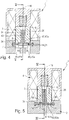
- the Figures 1 and 2 and FIGS. 7 and 8 each show a first switching position, which is a closed position.
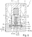
- the FIGS. 4 to 6 and FIGS. 10 and 11 each show a second switching position, which is an example of an open position.
- the valve member 3 is preferably formed as a composite element, which is composed of a membrane body 5 and at least one membrane carrier 5 carrying the membrane carrier 6. These components are secured together in a manner yet to be explained. While the membrane carrier 6 consists of a rigid material, for example of a rigid plastic material or of metal, the membrane body 5 is made of a flexible and preferably rubber-elastic material. Preferably, the membrane body 5 is an elastomeric body.
- valve chamber 7 In the interior of the valve housing 2 is a valve chamber 7 forming a cavity.
- the valve chamber 7 is delimited on the one hand by the valve housing 2 and on the other hand by a membrane-like constituent of the membrane body 5 designated as a sealing membrane 8.
- the valve housing 2 defines a bottom wall 12 delimiting the valve chamber 7 on a lower side.
- the bottom wall 12 is preferably part of a first housing part 13 of the valve housing 2.
- the sealing membrane 8 has a planar extension and extends over the bottom wall 12 at an upper side. With a the outer contour of the sealing membrane 8 defining outer edge region 14, the sealing membrane 8 is fixed so under sealing on the valve housing 2, that they share with the bottom wall 12 bounded to the environment sealed valve chamber 7.
- the fluid-tight fixation of the outer edge region 14 is expediently realized in that this outer edge region 14 is firmly clamped between the first housing part 13 and a second housing part 15 of the valve housing 2.
- the sealing membrane 8 in this context expediently has a fastening bead 21 which determines the outer contour of the sealing membrane 8. This engages in each case an annular groove, which are formed opposite to each other on the mutually facing surfaces of the first and second housing part 13, 15.
- the valve chamber 7 has a main axis 17 and a transverse axis 18 perpendicular thereto in the embodiment of the FIGS. 7 to 11 the valve chamber 7 preferably has an elongated shape, the main axis 17 forming the longitudinal axis. In the area of the narrow sides, the valve chamber 7 is in particular rounded here. That the valve chamber can also have a different outline, illustrate the FIGS. 1 to 6 , In this embodiment, the valve chamber 7, viewed in the height direction 16, has a circular outline. The contours mentioned apply to the same extent for the respective associated sealing membrane 8, wherein the outline of the sealing membrane 8 is determined in particular by the course of the outer edge region 14.
- each valve chamber 7 is bounded by a side wall 22 which determines the above-mentioned contour. It towers over one of the sealing membrane 8 facing bottom surface 23 of the valve chamber 7, which is formed on the bottom wall 12 at the top.
- the membrane body 5 has a preferably integrally formed with the sealing membrane 8 fastening extension 24 which protrudes in the height direction 16 in the direction of the membrane support 6.
- the membrane body 5 is attached to the membrane support 6.
- the attachment extension 24 in the central region of the sealing membrane 8. Deviating from this he is in the embodiment of FIGS. 7 to 11 arranged eccentrically on the sealing membrane 8 in the axial direction of the main axis 17.
- the membrane carrier 6 is located on the bottom wall 12 in the height direction 16 opposite side of the sealing membrane 8.
- the sealing membrane 8 is therefore in the height direction 16 between the valve chamber 7 and the membrane support. 6
- the membrane support 6 is mounted linearly movable relative to the valve housing 2.
- the movement that can be carried out by the membrane support 6 will be referred to below as a switching movement 26 because it has an immediate effect on the switching position of the valve member 3.
- the switching movement 26 is preferably a linear movement and extends in the embodiments in the height direction 16. Accordingly, the membrane support 6 is movable in the height direction 16 by performing a linear switching movement 26. In this case, depending on the direction of movement, an approach to the bottom wall 12 or a removal of the bottom wall 12 by the membrane carrier 6 takes place.
- a portion of the sealing membrane 8 makes the switching movement 26 of the membrane carrier 6 without any restrictions.
- This is a membrane section of the sealing membrane 8, referred to below as a fastening membrane section 36, via which the sealing membrane 8 is fastened to the membrane support 6.
- the exemplary embodiments have in common that the sealing membrane 8 is fastened in the region of the attachment membrane section 36 exclusively in the interior of the membrane carrier 6.
- the attachment extension 24 is arranged directly on the attachment membrane section 36 and engages from the side of a sealing membrane 8 facing base 38 of the membrane carrier 6 ago in a base 38 open towards the mounting recess 43 of the membrane carrier 6 inside.
- the base surface 38 is preferably planar and extends in particular at right angles to the height direction 16 and / or the direction of the switching movement 26.
- the attachment extension 24 is fixed in the mounting recess 43 so that it directly participates in the linear switching movement 26 of the membrane carrier 6. Consequently, this also applies to the fastening diaphragm section 36, which is arranged directly on the fastening extension 24 and lies outside the fastening recess 43. In both embodiments, the attachment membrane portion 36 is associated with the central area of the base 38.
- the sealing membrane 8 is expediently held exclusively in the area of the attachment membrane section 36 on the membrane support 6. More specifically, the fixed connection results from the interaction between the inner circumference of the fastening recess 43 and the fastening extension 24 immersed in the fastening recess 43. Between the two components, in the exemplary embodiments there is a material connection which is realized by means of an adhesive which is not apparent in the drawing , Additionally or alternatively, however, a frictional connection is possible. Furthermore, the attachment recess 43 may also be contoured so that it additionally or alternatively with the attachment extension 24 in the height direction 16 positive connection is received. The latter can be realized, for example, in that the attachment recess 43 has at least one constriction which engages or presses into a constricted or waisted peripheral region of the attachment extension 24 in the radial direction with respect to the height direction 16.
- valve chamber 7 open a plurality of the valve housing 2 passing through fluid channels 45 a.
- the diaphragm valve 1 is used here as a shut-off valve with 2/2-valve function. If a diaphragm valve 1 with a higher valve functionality is to be realized, for example with a 3/2 valve function, at least three and preferably exactly three fluid channels open into the valve chamber 7. This applies to the embodiment of FIG. 12 to.
- first and second fluid channels 45 are also referred to below as the first and second fluid channels 45a, 45b for better distinction.
- Both fluid channels 45a, 45b suitably pass through the bottom wall 12 and open at the bottom surface 23, each with a channel mouth 46 in the valve chamber 7 a.
- the channel openings 46 are referred to as first and second channel openings 46a, 46b.
- the diaphragm valve 1 can in the embodiments of FIGS. 1 to 11 depending on the switching position of the valve member 3, the two fluid channels 45a, 45b either fluid-tightly separate from each other or, through the valve chamber 7 through, fluidly interconnect. The latter happens in the above-mentioned open position of the valve member 3. To separate the fluid connection, the valve member 3 is displaced into the closed position.
- valve member 3 cooperates with a stationary with respect to the valve housing 2 arranged valve seat 47.
- the illustrated diaphragm valves 1 differ from each other in the structure of their valve seat 47th Die Ventilsitz 47 according to the embodiment of FIGS. 1 to 6 is web-like and therefore hereinafter referred to as web-like valve seat 47a.
- Each valve seat 47 of the embodiment of FIGS. 7 to 11 and the FIG. 12 is ring-shaped closed in itself and will therefore hereinafter also referred to as annular valve seat 47b.
- the web-like valve seat 47a extends in the valve chamber 7 transversely to the height direction 16 between itself in particular diametrically opposite lateral wall portions 22a, 22b of the side wall 22. In this way, the valve chamber 7 is divided by the web-like valve seat 47a in two chamber sections 52a, 52b which each one of the two channel mouth 46a, 46b is located.
- the web-like valve seat 47a has a FIG. 5 easily recognizable linear longitudinal extent.
- first channel opening 46a is framed by an annular valve seat 47b, which is preferably raised like a collar on the bottom surface 23 and protrudes upward from there in the height direction 16 in the direction of the sealing membrane 8.
- the sealing membrane 8 extends across the valve seat 47 in all embodiments. It has in a valve seat 47 in the height direction 16 opposite Area over a sealing portion 53, which is the base 38 in the height direction 16 upstream and which in the execution of the switching movement 26 depending on the direction of movement through the membrane support 6 to the associated valve seat 47 fluidly pressed or lifted from the valve seat 47. In the closed position of the valve member 3, the sealing portion 53 sealingly abuts the associated valve seat 47, while it is lifted in the open position of the valve member 3 of this valve seat 47.
- the sealing portion 53 is that portion of the sealing membrane 8, which can be brought to bear on the associated valve seat 47. Its shape therefore corresponds to that of the valve seat 47. Accordingly, the sealing portion 53 of the FIGS. 1 to 6 to a strip-shaped sealing portion 53 a and in the embodiments of the FIGS. 7 to 12 around an annular sealing portion 53b. Each sealing portion 53 is opposite to the valve seat 47 in the height direction 16.
- annular valve seat 47b is expediently wholly within the outer contour 54 of the sealing membrane 8 facing base 38 of the membrane support 6.
- This base 38 is formed in both embodiments of an axially oriented end face of the membrane support 6, which is preferably designed plunger-like.
- a web-like valve seat 47a it is according to FIGS. 1 to 6 advantageous if the web-like valve seat 47a is covered at least approximately over its entire length by the base 38 of the membrane carrier 6.
- the outer edge region 14 fixed to the valve housing 2 and the attachment membrane section 36 of the sealing membrane 8 are transversal arranged at a distance from one another to the height direction 16.
- the outer edge region 14 surrounds the attachment membrane portion 36 all around in the manner of a self-contained frame.
- the sealing membrane 8 furthermore has a special membrane section, which will be referred to below as a loose membrane section 55.
- This loose membrane portion 55 extends between the attachment membrane portion 36 and the outer edge region 14, wherein it is not attached to the membrane support 6 - except for the attachment membrane portion 36 - and the base 38 is loosely upstream. The only, a fixing effecting connection between the sealing membrane 8 and the membrane support 6 thus results through the attachment membrane portion 36. While this attachment membrane portion 36 directly participates the switching movement of the membrane support 6, the loose membrane portion 55 is able to from the Base surface 38 lift off when the diaphragm support 6 moves from the closed position to the open position and thereby removed from the valve seat 47.
- the sealing portion 53 is at least partially part of the loose membrane portion 55.
- the sealing portion 53 is at least partially lifted from the base 38 in the direction of the switching movement 26.
- the loose membrane portion 55 component of the sealing portion 53 which is also referred to below as unfixed component 32 of the sealing portion 53, therefore applies that it is supported in the closed position of the valve member 3 of the base 38 of the diaphragm support 6 and the valve seat 47th is pressed while it is lifted in the open position of the valve member 3 both from the valve seat 47 and in an advantageous manner from the base 38 of the membrane carrier 6.
- the membrane valve 1 can be designed so that only a portion of the sealing portion 53 forms a part of the loose membrane portion 55.
- the strip-shaped sealing section 53a here extends partly over the fastening membrane section 36 and partly over the loose membrane section 55. Accordingly, the sealing section 53 has one of the fastening membrane section 36 formed fixed component 33 and at least one of the loose membrane portion 55 formed unfixed component 32. In the embodiment in which the strip-shaped sealing portion 53a extends diametrically across the base 38 away, therefore, only the two unfixed components 32 of the sealing portion 53 fold away from the membrane support 6.
- the diaphragm valve 1 can also be designed such that the sealing section 53 in its entirety is a component of the loose diaphragm section 55. This is in the embodiments of FIGS. 7 to 12 the case.
- the here annular-shaped sealing portion 53, 53b extends at a transverse distance and in particular at a radial distance to the attachment membrane portion 36 around this attachment membrane portion 36 around, so that it can completely lift off from the base 38 of the membrane support 6, if this at his Shifting movement 26 away from the annular valve seat 47b.
- the loose membrane portion 55 expediently contains, viewed in the height direction 16, the outer contour 54 of the base surface 38 surrounding the surrounding membrane outer portion 56, which merges into the outer edge region 14.
- the embodiments of the FIGS. 7 to 12 show such an embodiment. Since this membrane outer portion 56 is not covered by the membrane support 6, he experiences through the membrane support 6 no support against the pressure prevailing in the valve chamber 7 fluid pressure. However, so that the membrane outer portion 56 does not experience excessive stress even at high fluid pressures, it is expediently covered on its upper side facing away from the valve chamber 7 by a support wall 48 of the valve housing 2 unfolding a supporting action with respect to the outer membrane portion 56.
- the support wall It protrudes from the outer edge region 14 facing the outer side over the sealing membrane 8 away and preferably extends into the immediate vicinity of the membrane support 6, which expediently passes through a wall opening 44 of the support wall 48 slidably linearly ,
- the axial support of the membrane outer portion 56 is possible without functional impairment of the valve member 3, because the sealing membrane 8 in the region of the loose membrane portion 55 has the necessary freedom of movement to ensure the lifting movement of the membrane support 6 including the associated sealing portion 53.
- the diaphragm valve 1 can also be designed such that the outer edge region 14 fixed to the valve housing 2 adjoins the component of the sealing membrane 8 extending to the outer contour 54 directly. This applies to the embodiment of FIGS. 1 to 6 to.
- the diaphragm body 5 covers with its base 38 the entire cross-sectional area of the valve chamber 7.
- the sealing membrane 8 Due to the given for the loose membrane portion 55 possibility to stand out from the membrane support 6 or fold away from the membrane support 6 or fold away, there is the advantageous possibility to realize the sealing membrane 8 as a whole with a planar structure without bulges.
- the best example of this is the design of the FIGS. 1 to 6 in which the sealing membrane 8 with the exception of the fixing bead 21 has a planar shape with a substantially constant wall thickness.
- the sealing membrane 8, in particular in the region of the outer contour 54 of the membrane carrier 6, a viewed in the height direction 16 preferably have annular deformation portion 60 which has at least one bulge.
- existing electric drive means 4 expediently each include a spring device 57, which is supported between the valve housing 2 and the membrane support 6 and constantly acting in such an oppressive manner on the membrane support 6 that selbiger is biased in the above-mentioned closed position.
- This closed position thus defines the basic position of the diaphragm valve 1 in both embodiments.
- the drive means 4 in particular include a schematically indicated electromagnetic device 58, which contains an electromagnetically drivable drive member 63, which is formed by an electromagnetically driven armature of the solenoid device 58.
- This anchor is in the embodiments of FIGS. 1 to 11 formed in unit with the membrane carrier 6.
- the solenoid device 58 Upon activation of the solenoid device 58, a magnetic force is generated, which moves the membrane support 6, overcoming the restoring force of the spring device 57 in the open position.
- the spring device 57 is expediently a component of the electromagnetic device 58.
- the drive means 4 may also be of a different type than the one described.
- the diaphragm valve 1 is a single membrane body 5 functionally divided into two sealing membranes 8, which are each connected to a separate membrane support 6, so that they can cooperate with their own valve seat 47, 47b.
- Both membrane supports 6 are expediently formed plunger-like and guided parallel to each other linearly movable, wherein they are drivingly coupled to each other, that approximates a membrane support 6 to its associated valve seat 47, 47b, when the other membrane support 6 of the associated valve seat 47th , 47b is lifted.
- the drive-like coupling can be realized in particular by means of a rocker-like pivotable actuating lever 62, which can be driven by the drive means 4 to a reciprocating pivoting movement 65 and which has two drive arms 67, 68, which cooperate with one of the two membrane carrier 6.
- the pivotal movement 65 of the actuating lever 62 is converted into the linear switching movement of the two membrane carrier 6.
- FIG. 12 is different from the one of FIGS. 7 to 11 in particular by an additional third fluid channel 45c, which opens into the valve chamber 7 via a third channel opening 46c, which, like the first channel opening 46a, is assigned a valve seat 47, which in turn is an annular valve seat 47b.
- each of these annular valve seats 47b is opposite one of the two membrane supports 6, on each of which one of the two sealing membranes 8, ie in each case a membrane section of the membrane body, extends over each of these two valve seats 74b 5, in the same manner in the region of a membrane-mounting portion 36 is attached as in the embodiment of FIGS. 7 to 11 , It can be said that in the embodiment of the FIG. 12 the basis of the FIGS.
- the second fluid passage 45b is alternately connectable with either the first fluid passage 45a or the third fluid passage 45c and simultaneously separable from the other fluid passage 45c and 45a, respectively.
- the drive means 4 also included in the embodiment of FIG. 12 electrically actuatable drive means 4, which expediently include a schematically indicated electromagnetic device 58 with an electromagnetically drivable drive member 63.
- the drive member 63 exerts a pivoting movement 65 causing driving force on the actuating lever 62, wherein it has expediently overcome a restoring force of a spring device 57.
- pivot bearing means are visible, through which the actuating lever 62 is pivotally mounted relative to the valve housing 2 to enable the pivoting movement 65.
- the membrane carrier 6 is integrally formed.
- the sealing membrane 8 can be mounted on a multi-part membrane carrier in such a way that it is inserted into the membrane carrier and then fixed with a sleeve which at the same time forms a storage means for an axle shaft serving for the pivotable mounting of the membrane carrier.
- the sealing membrane 8 or the membrane body 5 can also be fixed by clamping between two parts of the membrane carrier 6.
Landscapes
- Engineering & Computer Science (AREA)
- General Engineering & Computer Science (AREA)
- Mechanical Engineering (AREA)
- Fluid-Driven Valves (AREA)
- Reciprocating Pumps (AREA)
Claims (15)
- Soupape à membrane, avec un carter de soupape (2) et au moins un organe de soupape (3) mobile par rapport à ce dernier, dans laquelle l'organe de soupape (3) dispose d'un support de membrane (6) pouvant être déplacé par rapport au carter de soupape (2) en exécutant un déplacement de commutation (26) et d'une membrane d'étanchéité (8) flexible délimitant conjointement avec le carter de soupape (2) une chambre de soupape (7), dans laquelle la membrane d'étanchéité (8) est fixée, au niveau de sa zone de bord (14) extérieure, au niveau du carter de soupape (2) moyennant une étanchéification et présente une section de membrane d'attache (36) attachée à distance au niveau du support de membrane (6) et accompagnant le déplacement de commutation (26) dudit support de membrane, dans laquelle un siège de soupape (47) tourné vers la membrane d'étanchéité (8) est disposé dans la chambre de soupape (7), au niveau duquel siège de soupape une section étanche (53) de la membrane d'étanchéité (8) soutenue au moins en partie par une surface de base (38), tournée vers la chambre de soupape (7), du support de membrane (6) peut être appuyée de manière à assurer l'étanchéité afin de séparer les uns des autres au moins deux canaux de fluide (45, 45a, 45b) débouchant dans la chambre de soupape (7), dans laquelle la soupape à membrane (1) contient un corps de membrane (5), qui est divisé de manière fonctionnelle en deux membranes d'étanchéité (8), qui sont reliées respectivement à un support de membrane (6) propre et qui peuvent coopérer avec respectivement un siège de soupape (47) propre, dans laquelle les deux supports de membrane (6) sont réalisés à la manière d'un poussoir et peuvent être déplacés linéairement de manière parallèle l'un par rapport à l'autre en exécutant un déplacement de commutation (26) linéaire et dans laquelle les deux supports de membrane (6) sont couplés l'un à l'autre par ailleurs en entraînement au moyen d'un levier d'actionnement (62) pouvant pivoter à la manière d'une bascule de telle manière que l'au moins un support de membrane (6) se rapproche du siège de soupape (47) qui lui est associé quand l'autre support de membrane (6) est détaché du siège de soupape (47) qui lui est associé, dans laquelle le levier d'actionnement (62) peut être entraîné par des moyens d'entraînement (4) de la soupape à membrane (1) pouvant être actionnés de manière électrique pour effectuer un déplacement par pivotement (65) en va-et-vient et dispose de deux bras d'entraînement (67, 68), qui coopèrent avec respectivement un des deux supports de membrane (6) si bien que le déplacement par pivotement (65) du levier d'actionnement (62) est converti en le déplacement de commutation (26) linéaire des deux supports de membrane (6), caractérisée en ce que la section étanche (53) fait partie intégrante au moins en partie d'une section de membrane lâche de la membrane d'étanchéité (8), qui s'étend, sans avoir à être attachée au niveau du support de membrane (6), en partant de la section de membrane d'attache (36) jusqu'à la zone de bord (14) extérieure, fixée au niveau du carter de soupape (2), de la membrane d'étanchéité (8) de sorte qu'elle se détache de la surface de base (38) du support de membrane (6) quand le support de membrane (6) s'éloigne du siège de soupape (47) lors de son déplacement de commutation (26).
- Soupape à membrane selon la revendication 1, caractérisée en ce que le support de membrane (6) présente une surface frontale formant la surface de base (38).
- Soupape à membrane selon la revendication 2, caractérisée en ce que la section de membrane d'attache (36) est disposée dans la zone de la surface de base (38) du support de membrane (6) à une distance radiale de toutes parts par rapport au contour (54) extérieur de la surface de base (38) à l'intérieur dudit contour (54), dans laquelle elle se trouve de manière appropriée dans la zone centrale de la surface de base (38).
- Soupape à membrane selon l'une quelconque des revendications 1 à 3, caractérisée en ce que la section de membrane (55) lâche encadre tout autour la section de membrane d'attache (36) dans une zone recouverte par la surface de base (38).
- Soupape à membrane selon l'une quelconque des revendications 1 à 4, caractérisée en ce que le siège de soupape (47, 47b) est réalisé de manière fermée sur lui de manière à présenter une forme annulaire d'une manière encadrant l'embouchure de canal (46b) d'un canal de fluide (45b), dans laquelle la section étanche (53, 53b) associée de la membrane d'étanchéité (8) est réalisée également de manière à présenter une forme annulaire et fait partie au moins de la section de membrane (55) lâche.
- Soupape à membrane selon la revendication 5, caractérisée en ce que la section étanche (53, 53b) de forme annulaire fait partie intégrante dans son ensemble de la section de membrane (55) lâche de sorte qu'elle peut se détacher totalement de la surface de base (38) du support de membrane (6) quand ce dernier s'éloigne du siège de soupape (47, 47b) lors de son déplacement de commutation (26).
- Soupape à membrane selon l'une quelconque des revendications 1 à 4, caractérisée en ce que le siège de soupape (47, 47a) est réalisé à la manière d'une entretoise de manière à s'étendre entre deux sections de paroi (22a, 22b) latérales de la chambre de soupape (7) et à diviser la chambre de soupape (7) en deux sections de chambre (52a, 52b), dans laquelle la section étanche (53, 53a) associée est réalisée de manière à présenter une forme de bande et fait partie au moins de la section de membrane (55) lâche.
- Soupape à membrane selon la revendication 7, caractérisée en ce que la section étanche (53) est formée en partie par la section de membrane d'attache (36) de sorte qu'elle peut se détacher seulement en partie de la surface de base (38) du support de membrane (6) quand ce dernier s'éloigne du siège de soupape (47) lors de son déplacement de commutation (26), dans laquelle la section de membrane d'attache (36) est disposée de manière appropriée entre deux parties constitutives (32), pouvant être détachées du support de membrane (6), de la section étanche (53).
- Soupape à membrane selon l'une quelconque des revendications 1 à 8, caractérisée en ce que la membrane d'étanchéité (8) est attachée au niveau du support de membrane (6) exclusivement dans son espace intérieur.
- Soupape à membrane selon l'une quelconque des revendications 1 à 9, caractérisée en ce que la membrane d'étanchéité (8) fait partie intégrante d'un corps de membrane (5) d'un seul tenant, qui présente, dans la zone de la section de membrane d'attache (36), au moins un prolongement d'attache (24) venant en prise avec le support de membrane (6) en partant de la surface de base (38).
- Soupape à membrane selon l'une quelconque des revendications 1 à 10, caractérisée en ce que la section de membrane (55) lâche de la membrane d'étanchéité (8) tout autour de la surface de base (38) du support de membrane (6) dépasse du contour (54) extérieur de la surface de base (38) et présente une section extérieure de membrane (56) encadrant côté extérieur la surface de base (38), laquelle section extérieure de membrane devient la zone de bord (14) extérieure fixée au niveau du carter de soupape (2).
- Soupape à membrane selon la revendication 11, caractérisée en ce que la section extérieure de membrane (56) de la membrane d'étanchéité (8) est recouverte et peut être soutenue par une paroi d'appui (48) du carter de soupape (2) au niveau de son côté supérieur opposé à la chambre de soupape (7), laquelle paroi d'appui s'étend de manière appropriée jusqu'au support de membrane (6).
- Soupape à membrane selon l'une quelconque des revendications 1 à 12, caractérisée en ce que la chambre de soupape (7) et la membrane d'étanchéité (8) ont respectivement un contour rond ou un contour oblong, arrondi de manière préférée au niveau des côtés étroits.
- Soupape à membrane selon l'une quelconque des revendications 1 à 13, caractérisée en ce que débouchent dans la chambre de soupape (7) trois canaux de fluide (45), respectivement un des deux sièges de soupape (47, 47b) de forme annulaire étant associé à deux des canaux de fluide (45, 45a, 45c), lesquels coopèrent respectivement avec une des deux garnitures étanches (8) réalisées en tant que partie constitutive intégrante du corps de membrane (5) d'un seul tenant.
- Soupape à membrane selon l'une quelconque des revendications 1 à 14, caractérisée en ce que le siège de soupape (47, 47b) est réalisé de manière fermée sur lui de manière à présenter une forme annulaire de manière à encadrer l'embouchure de canal (46b, 46c) d'un canal de fluide (45b, 45c), dans laquelle la section étanche (53, 53b) associée de la membrane d'étanchéité (8) est réalisée également de manière à présenter une forme annulaire et fait partie intégrante de la section de membrane (55) lâche de sorte qu'elle peut se détacher totalement de la surface de base (38) du support de membrane (6) quand ce dernier s'éloigne du siège de soupape (47, 47b) lors de son déplacement de commutation (26), dans laquelle la membrane d'étanchéité (8) fait partie intégrante d'un corps de membrane (5) d'un seul tenant, qui présente, dans la zone de la section de membrane d'attache (36), au moins un prolongement d'attache (24) venant en prise avec le support de membrane (6) en partant de la surface de base (38) et dans laquelle à la fois la chambre de soupape (7) et le corps de membrane ont un contour oblong, arrondi au niveau des côtés étroits.
Applications Claiming Priority (2)
| Application Number | Priority Date | Filing Date | Title |
|---|---|---|---|
| DE102012005093A DE102012005093A1 (de) | 2012-03-14 | 2012-03-14 | Membranventil |
| PCT/EP2013/000715 WO2013135366A1 (fr) | 2012-03-14 | 2013-03-11 | Soupape à diaphragme |
Publications (2)
| Publication Number | Publication Date |
|---|---|
| EP2817543A1 EP2817543A1 (fr) | 2014-12-31 |
| EP2817543B1 true EP2817543B1 (fr) | 2018-04-25 |
Family
ID=47901006
Family Applications (1)
| Application Number | Title | Priority Date | Filing Date |
|---|---|---|---|
| EP13710295.0A Active EP2817543B1 (fr) | 2012-03-14 | 2013-03-11 | Soupape à diaphragme |
Country Status (5)
| Country | Link |
|---|---|
| US (1) | US9476510B2 (fr) |
| EP (1) | EP2817543B1 (fr) |
| CN (1) | CN104302957B (fr) |
| DE (1) | DE102012005093A1 (fr) |
| WO (1) | WO2013135366A1 (fr) |
Cited By (3)
| Publication number | Priority date | Publication date | Assignee | Title |
|---|---|---|---|---|
| DE102019212063A1 (de) * | 2019-08-12 | 2021-02-18 | Festo Se & Co. Kg | Membranventil |
| DE102019212062A1 (de) * | 2019-08-12 | 2021-02-18 | Festo Se & Co. Kg | Membranventil und Verfahren zur Herstellung eines Membranventils |
| DE102019218093A1 (de) * | 2019-11-22 | 2021-05-27 | Festo Se & Co. Kg | Membranventil |
Families Citing this family (22)
| Publication number | Priority date | Publication date | Assignee | Title |
|---|---|---|---|---|
| JP6049685B2 (ja) | 2011-03-23 | 2016-12-21 | ネクステージ メディカル インコーポレイテッド | 腹膜透析使い捨てユニット、コントローラ、腹膜透析システム |
| DE102012025411A1 (de) * | 2012-12-20 | 2014-07-10 | Borgwarner Inc. | Schubumluftventil eines Abgasturbolader-Verdichters |
| DE102014114212A1 (de) * | 2014-09-30 | 2016-03-31 | Bürkert Werke GmbH | Membranventil |
| US10344876B2 (en) * | 2015-06-23 | 2019-07-09 | Entegris, Inc. | Oblong diaphragm valves |
| DE102016204956B4 (de) | 2016-03-24 | 2023-01-12 | Festo Se & Co. Kg | Membranventil |
| DE102016206784B3 (de) * | 2016-04-21 | 2017-10-26 | Festo Ag & Co. Kg | Fluidverteilervorrichtung |
| IL246151B (en) | 2016-06-09 | 2021-02-28 | Dorot Man Control Valves Ltd | From a diaphragm body and its diaphragm |
| DE102016009402A1 (de) * | 2016-08-02 | 2018-02-08 | Wabco Europe Bvba | Membranventilanordnung |
| DE102016224128B4 (de) | 2016-12-05 | 2018-11-15 | Festo Ag & Co. Kg | Ventilanordnung |
| US20180373274A1 (en) * | 2017-06-27 | 2018-12-27 | Walbro Llc | Diaphragm regulator for higher pressure input gas |
| CN109927299A (zh) * | 2017-12-18 | 2019-06-25 | 塞德流量控制有限责任公司 | 用于膜片阀的膜片及其制造方法 |
| CN108167490A (zh) * | 2017-12-28 | 2018-06-15 | 天津市仕联能源科技有限公司 | 一种抗压平衡阀 |
| KR102763265B1 (ko) * | 2018-05-22 | 2025-02-07 | 컴파트 시스템즈 피티이. 엘티디. | 가변 제어 오리피스 밸브 |
| DE102018216876B4 (de) | 2018-10-01 | 2022-10-27 | Conti Temic Microelectronic Gmbh | Pneumatisches Ventil |
| ES2953306T3 (es) * | 2019-05-29 | 2023-11-10 | Fischer G Rohrleitungssysteme Ag | Puesta en marcha de válvula de diafragma |
| US12202446B2 (en) | 2019-09-12 | 2025-01-21 | A. Raymond Et Cie | Flow control valve and system for cleaning a vehicle surface |
| EP3792535A1 (fr) | 2019-09-12 | 2021-03-17 | A. Raymond et Cie | Vanne de régulation de débit et système de nettoyage d'une surface de véhicule |
| DE102020207475A1 (de) * | 2020-06-17 | 2021-12-23 | Festo Se & Co. Kg | Ventileinrichtung |
| US11719361B2 (en) | 2021-02-09 | 2023-08-08 | Saudi Arabian Oil Company | Remote seals for self-regulating valves |
| DE102021208274A1 (de) | 2021-07-30 | 2023-02-02 | Festo Se & Co. Kg | Membranventil |
| JP7712663B2 (ja) | 2021-09-06 | 2025-07-24 | アドバンス電気工業株式会社 | ダイアフラム弁 |
| US12326197B2 (en) * | 2022-05-12 | 2025-06-10 | Unibloc Hygienic Technologies Us, Llc | Bi-directional relief valve |
Citations (1)
| Publication number | Priority date | Publication date | Assignee | Title |
|---|---|---|---|---|
| US6003552A (en) * | 1998-07-13 | 1999-12-21 | Automatic Switch Company | Rocker valve for sealing large orifices |
Family Cites Families (22)
| Publication number | Priority date | Publication date | Assignee | Title |
|---|---|---|---|---|
| GB596533A (en) * | 1945-07-30 | 1948-01-06 | George Harold Pearson | Improvements connected with stop valves |
| BE654379A (fr) * | 1963-10-14 | 1900-01-01 | ||
| DE7324333U (de) | 1973-06-30 | 1973-09-27 | Honeywell Gmbh | Magnetventil |
| US4836236A (en) * | 1987-07-29 | 1989-06-06 | Ladisch Thomas P | Flush sealing tank valve with diaphgram |
| US4944487A (en) * | 1989-05-08 | 1990-07-31 | Lee Company | Diaphragm valve |
| AT396622B (de) * | 1990-02-19 | 1993-10-25 | Avl Verbrennungskraft Messtech | Elektromagnetisch betätigbares ventil |
| CN1085297A (zh) * | 1993-08-26 | 1994-04-13 | 梧州市火柴厂 | 自保持微功耗膜片式直流电磁阀 |
| JP3701367B2 (ja) * | 1996-02-22 | 2005-09-28 | Smc株式会社 | ポペット弁 |
| JP3663463B2 (ja) | 1998-01-02 | 2005-06-22 | フルード マネージメント システムズ インコーポレイテッド | 弁座内のハードなチューブの流体チャンネルとフレシブルな密封ダイアフラムとを有するソレノイドバルブ |
| US6394417B1 (en) * | 1998-10-09 | 2002-05-28 | Swagelok Co. | Sanitary diaphragm valve |
| JP4247566B2 (ja) | 1999-04-14 | 2009-04-02 | Smc株式会社 | バルブ |
| FR2795798B1 (fr) | 1999-07-02 | 2001-08-31 | Asco Joucomatic | Perfectionnements apportes aux electrovannes du type a noyau isole du fluide |
| DE20023225U1 (de) | 1999-09-16 | 2003-07-10 | Alfmeier Präzision AG Baugruppen und Systemlösungen, 91757 Treuchtlingen | Pneumatische Wegeventilanordnung |
| US6609698B1 (en) * | 2000-10-25 | 2003-08-26 | Arichell Technologies, Inc. | Ferromagnetic/fluid valve actuator |
| US6789781B2 (en) * | 2001-03-16 | 2004-09-14 | Entegris, Inc. | Reinforced diaphragm valve |
| DE10143887C1 (de) | 2001-09-07 | 2003-04-24 | Imi Norgren Buschjost Gmbh & C | Membranventil |
| ITSV20020032A1 (it) * | 2002-07-09 | 2004-01-09 | Alberto Lodolo | Valvola a membrana ed otturatore per detta valvola |
| DE102005021583A1 (de) | 2005-05-10 | 2006-11-30 | Bürkert Werke GmbH & Co. KG | Ventilvorrichtung |
| US7926785B2 (en) * | 2005-06-22 | 2011-04-19 | Wincek Christopher P | Valve diaphragm with a compression restraining ring, and valve including same |
| CN101101069B (zh) | 2006-07-04 | 2010-12-22 | 深圳迈瑞生物医疗电子股份有限公司 | 微型阀 |
| DE202009000593U1 (de) | 2009-01-19 | 2009-03-19 | Bürkert Werke GmbH & Co. KG | Magnetventil |
| DE202009016447U1 (de) | 2009-12-03 | 2010-03-11 | Bürkert Werke GmbH | Fluidisches Steuerelement |
-
2012
- 2012-03-14 DE DE102012005093A patent/DE102012005093A1/de not_active Withdrawn
-
2013
- 2013-03-11 WO PCT/EP2013/000715 patent/WO2013135366A1/fr not_active Ceased
- 2013-03-11 EP EP13710295.0A patent/EP2817543B1/fr active Active
- 2013-03-11 CN CN201380014399.2A patent/CN104302957B/zh active Active
- 2013-03-11 US US14/384,511 patent/US9476510B2/en active Active
Patent Citations (1)
| Publication number | Priority date | Publication date | Assignee | Title |
|---|---|---|---|---|
| US6003552A (en) * | 1998-07-13 | 1999-12-21 | Automatic Switch Company | Rocker valve for sealing large orifices |
Cited By (6)
| Publication number | Priority date | Publication date | Assignee | Title |
|---|---|---|---|---|
| DE102019212063A1 (de) * | 2019-08-12 | 2021-02-18 | Festo Se & Co. Kg | Membranventil |
| DE102019212062A1 (de) * | 2019-08-12 | 2021-02-18 | Festo Se & Co. Kg | Membranventil und Verfahren zur Herstellung eines Membranventils |
| US11326705B2 (en) | 2019-08-12 | 2022-05-10 | Festo Se & Co. Kg | Diaphragm valve and a method for manufacturing a diaphragm valve |
| DE102019212063B4 (de) | 2019-08-12 | 2022-08-18 | Festo Se & Co. Kg | Membranventil |
| DE102019218093A1 (de) * | 2019-11-22 | 2021-05-27 | Festo Se & Co. Kg | Membranventil |
| DE102019218093B4 (de) * | 2019-11-22 | 2025-09-18 | Festo Se & Co. Kg | Membranventil |
Also Published As
| Publication number | Publication date |
|---|---|
| EP2817543A1 (fr) | 2014-12-31 |
| US20150041691A1 (en) | 2015-02-12 |
| WO2013135366A1 (fr) | 2013-09-19 |
| US9476510B2 (en) | 2016-10-25 |
| CN104302957B (zh) | 2017-10-13 |
| DE102012005093A1 (de) | 2013-09-19 |
| CN104302957A (zh) | 2015-01-21 |
Similar Documents
| Publication | Publication Date | Title |
|---|---|---|
| EP2817543B1 (fr) | Soupape à diaphragme | |
| DE69423617T2 (de) | Membranventil | |
| DE19849742B4 (de) | Ventil des Membrantyps | |
| DE3717341A1 (de) | Ventilanordnung mit hauptschaltventil und vorsteuerventil | |
| DE9319462U1 (de) | Kolbenpumpe zum Fördern von Hydraulikflüssigkeit in einer blockiergeschützten Fahrzeugbremsanlage | |
| EP0719395A1 (fr) | Systeme de soupape modulaire pour milieux en ecoulement | |
| DE2014087B2 (de) | Verwendung einer kupplung zwischen einem ventilverschlusstueck und einem ventilantriebselement | |
| DE1917860A1 (de) | Quetschventil | |
| DE3823569C2 (fr) | ||
| EP2530365A1 (fr) | Garniture de soupape pour une armature sanitaire | |
| AT504693B1 (de) | Selbsttätiges ringventil | |
| EP0085852B1 (fr) | Soupape à trois voies et deux positions | |
| EP0085298B1 (fr) | Soupape à voies multiples, en particulier pour utilisation dans des appareils de dialyse | |
| DE102012005122B4 (de) | Membranventil | |
| DE102014101339B4 (de) | Membranventil | |
| EP2924327A1 (fr) | Vanne multi-voies | |
| EP0745796B1 (fr) | Robinet modulaire | |
| DE69506723T2 (de) | Pneumatischer bremskraftverstärker mit reduzierter belastung und hysteresis | |
| DE102006062432B4 (de) | Modulares pneumatisches Schieberventil | |
| DE102019212062A1 (de) | Membranventil und Verfahren zur Herstellung eines Membranventils | |
| EP3935296B1 (fr) | Dispositif de régulation de débit d'un fluide | |
| EP1181471B1 (fr) | Unite d'obturation pour une soupape aseptique a double siege | |
| DE102013016548B3 (de) | Beweglicher Anker eines Magnetventils und damit ausgestattetes Magnetventil | |
| EP0561294A1 (fr) | Soupape à force équilibrée | |
| DE3236922A1 (de) | Bremszylinder fuer keilspreizbremsen |
Legal Events
| Date | Code | Title | Description |
|---|---|---|---|
| PUAI | Public reference made under article 153(3) epc to a published international application that has entered the european phase |
Free format text: ORIGINAL CODE: 0009012 |
|
| 17P | Request for examination filed |
Effective date: 20140605 |
|
| AK | Designated contracting states |
Kind code of ref document: A1 Designated state(s): AL AT BE BG CH CY CZ DE DK EE ES FI FR GB GR HR HU IE IS IT LI LT LU LV MC MK MT NL NO PL PT RO RS SE SI SK SM TR |
|
| AX | Request for extension of the european patent |
Extension state: BA ME |
|
| DAX | Request for extension of the european patent (deleted) | ||
| GRAP | Despatch of communication of intention to grant a patent |
Free format text: ORIGINAL CODE: EPIDOSNIGR1 |
|
| STAA | Information on the status of an ep patent application or granted ep patent |
Free format text: STATUS: GRANT OF PATENT IS INTENDED |
|
| INTG | Intention to grant announced |
Effective date: 20171208 |
|
| GRAS | Grant fee paid |
Free format text: ORIGINAL CODE: EPIDOSNIGR3 |
|
| GRAA | (expected) grant |
Free format text: ORIGINAL CODE: 0009210 |
|
| STAA | Information on the status of an ep patent application or granted ep patent |
Free format text: STATUS: THE PATENT HAS BEEN GRANTED |
|
| AK | Designated contracting states |
Kind code of ref document: B1 Designated state(s): AL AT BE BG CH CY CZ DE DK EE ES FI FR GB GR HR HU IE IS IT LI LT LU LV MC MK MT NL NO PL PT RO RS SE SI SK SM TR |
|
| REG | Reference to a national code |
Ref country code: GB Ref legal event code: FG4D Free format text: NOT ENGLISH |
|
| REG | Reference to a national code |
Ref country code: CH Ref legal event code: EP |
|
| REG | Reference to a national code |
Ref country code: AT Ref legal event code: REF Ref document number: 993280 Country of ref document: AT Kind code of ref document: T Effective date: 20180515 |
|
| REG | Reference to a national code |
Ref country code: IE Ref legal event code: FG4D Free format text: LANGUAGE OF EP DOCUMENT: GERMAN |
|
| REG | Reference to a national code |
Ref country code: DE Ref legal event code: R096 Ref document number: 502013010010 Country of ref document: DE |
|
| REG | Reference to a national code |
Ref country code: NL Ref legal event code: MP Effective date: 20180425 |
|
| REG | Reference to a national code |
Ref country code: LT Ref legal event code: MG4D |
|
| PG25 | Lapsed in a contracting state [announced via postgrant information from national office to epo] |
Ref country code: NL Free format text: LAPSE BECAUSE OF FAILURE TO SUBMIT A TRANSLATION OF THE DESCRIPTION OR TO PAY THE FEE WITHIN THE PRESCRIBED TIME-LIMIT Effective date: 20180425 |
|
| PG25 | Lapsed in a contracting state [announced via postgrant information from national office to epo] |
Ref country code: SE Free format text: LAPSE BECAUSE OF FAILURE TO SUBMIT A TRANSLATION OF THE DESCRIPTION OR TO PAY THE FEE WITHIN THE PRESCRIBED TIME-LIMIT Effective date: 20180425 Ref country code: PL Free format text: LAPSE BECAUSE OF FAILURE TO SUBMIT A TRANSLATION OF THE DESCRIPTION OR TO PAY THE FEE WITHIN THE PRESCRIBED TIME-LIMIT Effective date: 20180425 Ref country code: ES Free format text: LAPSE BECAUSE OF FAILURE TO SUBMIT A TRANSLATION OF THE DESCRIPTION OR TO PAY THE FEE WITHIN THE PRESCRIBED TIME-LIMIT Effective date: 20180425 Ref country code: LT Free format text: LAPSE BECAUSE OF FAILURE TO SUBMIT A TRANSLATION OF THE DESCRIPTION OR TO PAY THE FEE WITHIN THE PRESCRIBED TIME-LIMIT Effective date: 20180425 Ref country code: NO Free format text: LAPSE BECAUSE OF FAILURE TO SUBMIT A TRANSLATION OF THE DESCRIPTION OR TO PAY THE FEE WITHIN THE PRESCRIBED TIME-LIMIT Effective date: 20180725 Ref country code: FI Free format text: LAPSE BECAUSE OF FAILURE TO SUBMIT A TRANSLATION OF THE DESCRIPTION OR TO PAY THE FEE WITHIN THE PRESCRIBED TIME-LIMIT Effective date: 20180425 Ref country code: BG Free format text: LAPSE BECAUSE OF FAILURE TO SUBMIT A TRANSLATION OF THE DESCRIPTION OR TO PAY THE FEE WITHIN THE PRESCRIBED TIME-LIMIT Effective date: 20180725 |
|
| PG25 | Lapsed in a contracting state [announced via postgrant information from national office to epo] |
Ref country code: LV Free format text: LAPSE BECAUSE OF FAILURE TO SUBMIT A TRANSLATION OF THE DESCRIPTION OR TO PAY THE FEE WITHIN THE PRESCRIBED TIME-LIMIT Effective date: 20180425 Ref country code: RS Free format text: LAPSE BECAUSE OF FAILURE TO SUBMIT A TRANSLATION OF THE DESCRIPTION OR TO PAY THE FEE WITHIN THE PRESCRIBED TIME-LIMIT Effective date: 20180425 Ref country code: HR Free format text: LAPSE BECAUSE OF FAILURE TO SUBMIT A TRANSLATION OF THE DESCRIPTION OR TO PAY THE FEE WITHIN THE PRESCRIBED TIME-LIMIT Effective date: 20180425 Ref country code: GR Free format text: LAPSE BECAUSE OF FAILURE TO SUBMIT A TRANSLATION OF THE DESCRIPTION OR TO PAY THE FEE WITHIN THE PRESCRIBED TIME-LIMIT Effective date: 20180726 |
|
| PG25 | Lapsed in a contracting state [announced via postgrant information from national office to epo] |
Ref country code: PT Free format text: LAPSE BECAUSE OF FAILURE TO SUBMIT A TRANSLATION OF THE DESCRIPTION OR TO PAY THE FEE WITHIN THE PRESCRIBED TIME-LIMIT Effective date: 20180827 |
|
| REG | Reference to a national code |
Ref country code: DE Ref legal event code: R097 Ref document number: 502013010010 Country of ref document: DE |
|
| PG25 | Lapsed in a contracting state [announced via postgrant information from national office to epo] |
Ref country code: DK Free format text: LAPSE BECAUSE OF FAILURE TO SUBMIT A TRANSLATION OF THE DESCRIPTION OR TO PAY THE FEE WITHIN THE PRESCRIBED TIME-LIMIT Effective date: 20180425 Ref country code: SK Free format text: LAPSE BECAUSE OF FAILURE TO SUBMIT A TRANSLATION OF THE DESCRIPTION OR TO PAY THE FEE WITHIN THE PRESCRIBED TIME-LIMIT Effective date: 20180425 Ref country code: EE Free format text: LAPSE BECAUSE OF FAILURE TO SUBMIT A TRANSLATION OF THE DESCRIPTION OR TO PAY THE FEE WITHIN THE PRESCRIBED TIME-LIMIT Effective date: 20180425 Ref country code: CZ Free format text: LAPSE BECAUSE OF FAILURE TO SUBMIT A TRANSLATION OF THE DESCRIPTION OR TO PAY THE FEE WITHIN THE PRESCRIBED TIME-LIMIT Effective date: 20180425 Ref country code: RO Free format text: LAPSE BECAUSE OF FAILURE TO SUBMIT A TRANSLATION OF THE DESCRIPTION OR TO PAY THE FEE WITHIN THE PRESCRIBED TIME-LIMIT Effective date: 20180425 |
|
| PG25 | Lapsed in a contracting state [announced via postgrant information from national office to epo] |
Ref country code: SM Free format text: LAPSE BECAUSE OF FAILURE TO SUBMIT A TRANSLATION OF THE DESCRIPTION OR TO PAY THE FEE WITHIN THE PRESCRIBED TIME-LIMIT Effective date: 20180425 |
|
| PLBE | No opposition filed within time limit |
Free format text: ORIGINAL CODE: 0009261 |
|
| STAA | Information on the status of an ep patent application or granted ep patent |
Free format text: STATUS: NO OPPOSITION FILED WITHIN TIME LIMIT |
|
| 26N | No opposition filed |
Effective date: 20190128 |
|
| PG25 | Lapsed in a contracting state [announced via postgrant information from national office to epo] |
Ref country code: SI Free format text: LAPSE BECAUSE OF FAILURE TO SUBMIT A TRANSLATION OF THE DESCRIPTION OR TO PAY THE FEE WITHIN THE PRESCRIBED TIME-LIMIT Effective date: 20180425 |
|
| PG25 | Lapsed in a contracting state [announced via postgrant information from national office to epo] |
Ref country code: MC Free format text: LAPSE BECAUSE OF FAILURE TO SUBMIT A TRANSLATION OF THE DESCRIPTION OR TO PAY THE FEE WITHIN THE PRESCRIBED TIME-LIMIT Effective date: 20180425 |
|
| REG | Reference to a national code |
Ref country code: CH Ref legal event code: PL |
|
| PG25 | Lapsed in a contracting state [announced via postgrant information from national office to epo] |
Ref country code: LU Free format text: LAPSE BECAUSE OF NON-PAYMENT OF DUE FEES Effective date: 20190311 Ref country code: AL Free format text: LAPSE BECAUSE OF FAILURE TO SUBMIT A TRANSLATION OF THE DESCRIPTION OR TO PAY THE FEE WITHIN THE PRESCRIBED TIME-LIMIT Effective date: 20180425 |
|
| REG | Reference to a national code |
Ref country code: BE Ref legal event code: MM Effective date: 20190331 |
|
| PG25 | Lapsed in a contracting state [announced via postgrant information from national office to epo] |
Ref country code: IE Free format text: LAPSE BECAUSE OF NON-PAYMENT OF DUE FEES Effective date: 20190311 Ref country code: LI Free format text: LAPSE BECAUSE OF NON-PAYMENT OF DUE FEES Effective date: 20190331 Ref country code: CH Free format text: LAPSE BECAUSE OF NON-PAYMENT OF DUE FEES Effective date: 20190331 |
|
| REG | Reference to a national code |
Ref country code: DE Ref legal event code: R082 Ref document number: 502013010010 Country of ref document: DE Representative=s name: PATENTANWAELTE MAGENBAUER & KOLLEGEN PARTNERSC, DE Ref country code: DE Ref legal event code: R081 Ref document number: 502013010010 Country of ref document: DE Owner name: FESTO SE & CO. KG, DE Free format text: FORMER OWNER: FESTO AG & CO. KG, 73734 ESSLINGEN, DE Ref country code: DE Ref legal event code: R081 Ref document number: 502013010010 Country of ref document: DE Owner name: FESTO AG & CO. KG, DE Free format text: FORMER OWNER: FESTO AG & CO. KG, 73734 ESSLINGEN, DE |
|
| PG25 | Lapsed in a contracting state [announced via postgrant information from national office to epo] |
Ref country code: BE Free format text: LAPSE BECAUSE OF NON-PAYMENT OF DUE FEES Effective date: 20190331 |
|
| PG25 | Lapsed in a contracting state [announced via postgrant information from national office to epo] |
Ref country code: TR Free format text: LAPSE BECAUSE OF FAILURE TO SUBMIT A TRANSLATION OF THE DESCRIPTION OR TO PAY THE FEE WITHIN THE PRESCRIBED TIME-LIMIT Effective date: 20180425 |
|
| PG25 | Lapsed in a contracting state [announced via postgrant information from national office to epo] |
Ref country code: MT Free format text: LAPSE BECAUSE OF FAILURE TO SUBMIT A TRANSLATION OF THE DESCRIPTION OR TO PAY THE FEE WITHIN THE PRESCRIBED TIME-LIMIT Effective date: 20180425 |
|
| REG | Reference to a national code |
Ref country code: AT Ref legal event code: MM01 Ref document number: 993280 Country of ref document: AT Kind code of ref document: T Effective date: 20190311 |
|
| PG25 | Lapsed in a contracting state [announced via postgrant information from national office to epo] |
Ref country code: AT Free format text: LAPSE BECAUSE OF NON-PAYMENT OF DUE FEES Effective date: 20190311 |
|
| PG25 | Lapsed in a contracting state [announced via postgrant information from national office to epo] |
Ref country code: CY Free format text: LAPSE BECAUSE OF FAILURE TO SUBMIT A TRANSLATION OF THE DESCRIPTION OR TO PAY THE FEE WITHIN THE PRESCRIBED TIME-LIMIT Effective date: 20180425 |
|
| PG25 | Lapsed in a contracting state [announced via postgrant information from national office to epo] |
Ref country code: IS Free format text: LAPSE BECAUSE OF FAILURE TO SUBMIT A TRANSLATION OF THE DESCRIPTION OR TO PAY THE FEE WITHIN THE PRESCRIBED TIME-LIMIT Effective date: 20180825 |
|
| PG25 | Lapsed in a contracting state [announced via postgrant information from national office to epo] |
Ref country code: HU Free format text: LAPSE BECAUSE OF FAILURE TO SUBMIT A TRANSLATION OF THE DESCRIPTION OR TO PAY THE FEE WITHIN THE PRESCRIBED TIME-LIMIT; INVALID AB INITIO Effective date: 20130311 |
|
| PG25 | Lapsed in a contracting state [announced via postgrant information from national office to epo] |
Ref country code: MK Free format text: LAPSE BECAUSE OF FAILURE TO SUBMIT A TRANSLATION OF THE DESCRIPTION OR TO PAY THE FEE WITHIN THE PRESCRIBED TIME-LIMIT Effective date: 20180425 |
|
| P01 | Opt-out of the competence of the unified patent court (upc) registered |
Effective date: 20230623 |
|
| PGFP | Annual fee paid to national office [announced via postgrant information from national office to epo] |
Ref country code: IT Payment date: 20250331 Year of fee payment: 13 |
|
| PGFP | Annual fee paid to national office [announced via postgrant information from national office to epo] |
Ref country code: GB Payment date: 20260324 Year of fee payment: 14 |
|
| PGFP | Annual fee paid to national office [announced via postgrant information from national office to epo] |
Ref country code: DE Payment date: 20260325 Year of fee payment: 14 |
|
| PGFP | Annual fee paid to national office [announced via postgrant information from national office to epo] |
Ref country code: FR Payment date: 20260325 Year of fee payment: 14 |