EP2817543B1 - Diaphragm valve - Google Patents
Diaphragm valve Download PDFInfo
- Publication number
- EP2817543B1 EP2817543B1 EP13710295.0A EP13710295A EP2817543B1 EP 2817543 B1 EP2817543 B1 EP 2817543B1 EP 13710295 A EP13710295 A EP 13710295A EP 2817543 B1 EP2817543 B1 EP 2817543B1
- Authority
- EP
- European Patent Office
- Prior art keywords
- diaphragm
- valve
- sealing
- membrane
- section
- Prior art date
- Legal status (The legal status is an assumption and is not a legal conclusion. Google has not performed a legal analysis and makes no representation as to the accuracy of the status listed.)
- Active
Links
Images


Classifications
-
- F—MECHANICAL ENGINEERING; LIGHTING; HEATING; WEAPONS; BLASTING
- F16—ENGINEERING ELEMENTS AND UNITS; GENERAL MEASURES FOR PRODUCING AND MAINTAINING EFFECTIVE FUNCTIONING OF MACHINES OR INSTALLATIONS; THERMAL INSULATION IN GENERAL
- F16K—VALVES; TAPS; COCKS; ACTUATING-FLOATS; DEVICES FOR VENTING OR AERATING
- F16K7/00—Diaphragm valves or cut-off apparatus, e.g. with a member deformed, but not moved bodily, to close the passage ; Pinch valves
- F16K7/12—Diaphragm valves or cut-off apparatus, e.g. with a member deformed, but not moved bodily, to close the passage ; Pinch valves with flat, dished, or bowl-shaped diaphragm
- F16K7/126—Diaphragm valves or cut-off apparatus, e.g. with a member deformed, but not moved bodily, to close the passage ; Pinch valves with flat, dished, or bowl-shaped diaphragm the seat being formed on a rib perpendicular to the fluid line
-
- F—MECHANICAL ENGINEERING; LIGHTING; HEATING; WEAPONS; BLASTING
- F16—ENGINEERING ELEMENTS AND UNITS; GENERAL MEASURES FOR PRODUCING AND MAINTAINING EFFECTIVE FUNCTIONING OF MACHINES OR INSTALLATIONS; THERMAL INSULATION IN GENERAL
- F16K—VALVES; TAPS; COCKS; ACTUATING-FLOATS; DEVICES FOR VENTING OR AERATING
- F16K31/00—Actuating devices; Operating means; Releasing devices
- F16K31/02—Actuating devices; Operating means; Releasing devices electric; magnetic
- F16K31/06—Actuating devices; Operating means; Releasing devices electric; magnetic using a magnet, e.g. diaphragm valves, cutting off by means of a liquid
- F16K31/0603—Multiple-way valves
- F16K31/0641—Multiple-way valves the valve member being a diaphragm
-
- F—MECHANICAL ENGINEERING; LIGHTING; HEATING; WEAPONS; BLASTING
- F16—ENGINEERING ELEMENTS AND UNITS; GENERAL MEASURES FOR PRODUCING AND MAINTAINING EFFECTIVE FUNCTIONING OF MACHINES OR INSTALLATIONS; THERMAL INSULATION IN GENERAL
- F16K—VALVES; TAPS; COCKS; ACTUATING-FLOATS; DEVICES FOR VENTING OR AERATING
- F16K31/00—Actuating devices; Operating means; Releasing devices
- F16K31/02—Actuating devices; Operating means; Releasing devices electric; magnetic
- F16K31/06—Actuating devices; Operating means; Releasing devices electric; magnetic using a magnet, e.g. diaphragm valves, cutting off by means of a liquid
- F16K31/0644—One-way valve
- F16K31/0672—One-way valve the valve member being a diaphragm
-
- F—MECHANICAL ENGINEERING; LIGHTING; HEATING; WEAPONS; BLASTING
- F16—ENGINEERING ELEMENTS AND UNITS; GENERAL MEASURES FOR PRODUCING AND MAINTAINING EFFECTIVE FUNCTIONING OF MACHINES OR INSTALLATIONS; THERMAL INSULATION IN GENERAL
- F16K—VALVES; TAPS; COCKS; ACTUATING-FLOATS; DEVICES FOR VENTING OR AERATING
- F16K31/00—Actuating devices; Operating means; Releasing devices
- F16K31/02—Actuating devices; Operating means; Releasing devices electric; magnetic
- F16K31/06—Actuating devices; Operating means; Releasing devices electric; magnetic using a magnet, e.g. diaphragm valves, cutting off by means of a liquid
- F16K31/10—Actuating devices; Operating means; Releasing devices electric; magnetic using a magnet, e.g. diaphragm valves, cutting off by means of a liquid with additional mechanism between armature and closure member
-
- F—MECHANICAL ENGINEERING; LIGHTING; HEATING; WEAPONS; BLASTING
- F16—ENGINEERING ELEMENTS AND UNITS; GENERAL MEASURES FOR PRODUCING AND MAINTAINING EFFECTIVE FUNCTIONING OF MACHINES OR INSTALLATIONS; THERMAL INSULATION IN GENERAL
- F16K—VALVES; TAPS; COCKS; ACTUATING-FLOATS; DEVICES FOR VENTING OR AERATING
- F16K7/00—Diaphragm valves or cut-off apparatus, e.g. with a member deformed, but not moved bodily, to close the passage ; Pinch valves
- F16K7/12—Diaphragm valves or cut-off apparatus, e.g. with a member deformed, but not moved bodily, to close the passage ; Pinch valves with flat, dished, or bowl-shaped diaphragm
- F16K7/14—Diaphragm valves or cut-off apparatus, e.g. with a member deformed, but not moved bodily, to close the passage ; Pinch valves with flat, dished, or bowl-shaped diaphragm arranged to be deformed against a flat seat
Definitions
- the invention relates to a diaphragm valve, with a valve housing and at least one movable valve member, wherein the valve member has a movable under execution of a switching movement relative to the valve housing diaphragm carrier and a common with the valve housing a valve chamber limiting flexible sealing membrane, wherein the sealing membrane at its outer Fixed edge region is sealed to the valve housing and has a fixed thereto at a distance to the membrane carrier and its Umschaltschul mit mannerden attachment membrane portion, wherein in the valve chamber, a sealing membrane facing valve seat is arranged, to a at least partially facing from one of the valve chamber base of Membranismes supported sealing portion of the sealing membrane is sealingly pressed to separate at least two in the valve chamber opening fluid channels from each other, wherein the diaphragm valve is a membrane contains body which is functionally divided into two sealing membranes, which are each connected to its own membrane carrier and which can cooperate with its own valve seat, wherein the two membrane carriers are formed plunger-like and parallel linearly movable under execution of
- One from the EP 1 722 137 A2 known diaphragm valve includes at least one arranged in a valve housing valve member consisting of a valve chamber delimiting a sealing membrane and a sealing membrane supporting, designed in the manner of a plunger membrane carrier, which is linearly movable relative to the valve housing.
- the membrane carrier supports with its base an annular sealing portion of the sealing membrane, which can be brought into abutment against an annular valve seat arranged in the valve chamber in order to separate two fluid channels opening into the valve chamber from each other.
- the sealing portion is part of a diaphragm portion fixed to the valve member, which is referred to as a fastening membrane portion and which participates in the switching movement of the membrane carrier. At its outer edge region, the sealing membrane is clamped under sealing on the valve housing.
- a disadvantage of the known diaphragm valve is the fact that the sealing membrane is temporarily greatly expanded when switching the valve member and thus subject to high stress, which can adversely affect the life.
- a diaphragm valve of similar construction which has two valve members, each containing a plunger-like membrane carrier and a membrane carrier mounted on the, with a valve seat cooperating sealing membrane, wherein the sealing membranes are integrally combined in a membrane body.
- the DE 60017310 T2 discloses a diaphragm valve with a valve housing having a sealing membrane-bearing, pivotally mounted on a valve housing membrane carrier.
- the membrane carrier supports with its base two sealing portions of the sealing membrane, which can cooperate with each with its own valve seat to total three selectively connect to each other or separate from each other in a valve chamber opening fluid channels.
- the switching position of the valve carrier can be predetermined by drive means which act on the membrane carrier and cause its pivoting switching movement. Also in this diaphragm valve, the problem arises that the flexible sealing membrane is greatly stretched, especially in the membrane section extending between the membrane carrier and the fixed edge region, and is exposed to high tensile stresses.
- One from the DE 7324333 U known diaphragm valve has a sealing chamber closing a valve chamber, which is held by a stiffening plate. Protruding from the sealing membrane projections pass through the stiffening plate and are based on an independent of the sealing membrane in a valve housing pivotally mounted actuator. At the pivotal movement of the membrane carrier, the sealing membrane does not participate, which affects the available valve lift.
- the FR 2795798 A discloses a diaphragm valve whose valve member has a pivotable membrane carrier and a diaphragm body attached to the membrane carrier, wherein the membrane body forms a sealing membrane, the edge in the Valve housing is fixed under seal.
- a membrane section of the sealing membrane framing the membrane carrier is subject to a high tensile stress, which can impair the service life.
- the sealing portion is at least partially part of a loose membrane portion of the sealing membrane, which, without being attached to the membrane carrier, starting from the mounting diaphragm section to the fixed to the valve housing outer Edge region of the sealing membrane extends so that it lifts off from the base surface of the membrane carrier, when the membrane carrier moves away during its switching movement of the valve seat.
- a sealing section of the sealing membrane is further pressed by the membrane membrane-carrying membrane carrier under sealing against an associated valve seat.
- the sealing membrane is subject to only a slight elongation even when the sealing portion is lifted by appropriate switching movement of the membrane carrier from the associated valve seat.
- the reason for this is that at least a portion of the sealing portion belongs to a membrane portion of the sealing membrane which extends between the attachment membrane portion and the valve housing fixed to the outer edge region of the sealing membrane in the membrane carrier not fixed manner and therefore is able to move away from the Base surface of the membrane carrier to solve when the membrane carrier moves away during its switching movement of the associated valve seat.
- This unfixed membrane section is referred to as a loose membrane section.
- the sealing portion is thus mechanically supportable for fluid-tight interaction with the valve seat through the membrane carrier, at least a portion of the sealing portion has the ability to withdraw from the previously still resting on him base of the membrane support or detach from this base, if the membrane support for the purpose of Releasing a fluid connection in the sense of being moved away from the valve seat.
- a behavioral pattern can result here, which can be achieved by folding away or by folding away the loose membrane section could describe from the membrane carrier.
- a wedge-shaped widening gap between the loose membrane section and the membrane carrier can open up towards the edge of the base surface. Since the sealing membrane in the liftable from the membrane carrier areas is not forced to join the switching movement of the membrane carrier in full, it is subject to a relatively low strain.
- the diaphragm valve is equipped with electrically actuatable drive means which serve to actuate the valve member and which make it possible to drive the membrane carrier as needed to their switching movement and also to hold in the desired position.
- drive means preferably contain at least one electromagnetic device and preferably also at least one return spring device which predetermines a desired basic position.
- the sealing membrane is fastened with its attachment membrane portion in the region of the base surface of the membrane carrier such that there is a radial distance between this attachment membrane portion and the outline of the base area of the membrane carrier around the attachment membrane portion.
- the area of the sealing membrane located between the fastening membrane section and the outline of the base area is a component of the loose membrane section.
- the attachment membrane section is arranged in particular centrally in the region of the base surface. Particularly useful is an embodiment in which the loose membrane portion surrounds the attachment membrane portion in an area which is upstream of the base, all around. In this way, in particular results in an annular region of the loose membrane portion which is movable in the switching movement of the membrane carrier relative to the membrane carrier in order not to be forced to follow the switching movement of the membrane carrier in full and thereby exposed to a high strain load.
- valve seat of the diaphragm valve is formed annularly closed in itself, so that it framed the channel mouth of a fluid channel.
- a ring-shaped sealing portion of the sealing membrane on the valve seat is also a ring-shaped sealing portion of the sealing membrane on the valve seat.
- annular sealing portion at least a portion is formed as part of the loose membrane portion, so that it can lift off from the membrane carrier, when selbiger is moved away to release the fluid channel of the valve seat.
- the sealing membrane is formed so that a cooperating with an annular valve seat annular sealing portion in its entirety is a part of the loose membrane portion, so that it can lift off completely from the base of the membrane carrier, when the membrane carrier in the switching movement away from the valve seat , Basically, however, a design is possible in which the cooperating with the valve seat sealing portion is partially a part of the attachment membrane portion and only partially a part of the loose membrane portion.
- the sealing portion is expediently completely within the outer contour of the base of the membrane carrier.
- the valve seat is web-like and extends between two opposite lateral wall sections of the valve chamber, that it subdivides this valve chamber in two lying on this side and beyond the web-like valve seat chamber sections.
- the sealing portion which is strip-shaped in this case belongs at least partially to the loose membrane portion.
- a design is provided in which the sealing portion is partially formed by the attachment membrane portion, so that it can only partially lift off from the base of the membrane carrier.
- the sealing section expediently has two areas which can be lifted off from the membrane carrier and which flank the fastening membrane section on opposite sides.
- the sealing membrane is fastened in the region of the attachment membrane section exclusively in the interior of the membrane carrier.
- the sealing membrane is part of a one-piece membrane body having at least one and preferably exactly one starting from the base in the membrane carrier engaging fastening extension in the region of the attachment membrane portion.
- the base surface has an opening, wherein the base surface is designed in particular ring-shaped and preferably annular.
- the attachment of the sealing membrane in the interior of the membrane carrier takes place in particular exclusively on the basis of positive engagement and / or adhesion.
- a membrane body can be molded onto the membrane carrier during its production by means of an injection molding process, wherein an attachment extension engaging in the membrane carrier is formed.
- the sealing membrane is preferably designed so that it extends along the outer contour of the base of the membrane support all around the membrane support and having a base outside framing membrane outer portion which merges into the valve housing to seal fixed outer edge region.
- This membrane outer portion is expediently covered on its upper side facing away from the valve chamber by a support wall of the valve housing, so that it can withstand high fluid pressures prevailing in the valve chamber.
- the support wall has expediently an aperture through which the membrane carrier projects in a manner permitting the switching movement, with the advantage that the gap between the membrane carrier and the supporting wall can be kept very low.
- valve chamber and the sealing chamber closing the valve chamber have in particular a longitudinal shape with a narrow-side rounded outline or expediently have a round outline.
- the existing channel openings of the opening fluid channels are preferably arranged side by side, wherein they are arranged at an elongated valve chamber, in particular in the longitudinal direction of the valve chamber at a distance successively.
- the diaphragm valve designated in its entirety by reference numeral 1 has in all embodiments a valve housing 2 and a valve housing 2 arranged in the relative to the valve housing 2 movable valve member 3.
- the diaphragm valve 1 is preferably accommodated in the interior of the valve housing 2, electrically actuated Drive means 4 equipped by which the valve member 3 is switchable between two possible switching position.
- the Figures 1 and 2 and FIGS. 7 and 8 each show a first switching position, which is a closed position.
- the FIGS. 4 to 6 and FIGS. 10 and 11 each show a second switching position, which is an example of an open position.
- the valve member 3 is preferably formed as a composite element, which is composed of a membrane body 5 and at least one membrane carrier 5 carrying the membrane carrier 6. These components are secured together in a manner yet to be explained. While the membrane carrier 6 consists of a rigid material, for example of a rigid plastic material or of metal, the membrane body 5 is made of a flexible and preferably rubber-elastic material. Preferably, the membrane body 5 is an elastomeric body.
- valve chamber 7 In the interior of the valve housing 2 is a valve chamber 7 forming a cavity.
- the valve chamber 7 is delimited on the one hand by the valve housing 2 and on the other hand by a membrane-like constituent of the membrane body 5 designated as a sealing membrane 8.
- the valve housing 2 defines a bottom wall 12 delimiting the valve chamber 7 on a lower side.
- the bottom wall 12 is preferably part of a first housing part 13 of the valve housing 2.
- the sealing membrane 8 has a planar extension and extends over the bottom wall 12 at an upper side. With a the outer contour of the sealing membrane 8 defining outer edge region 14, the sealing membrane 8 is fixed so under sealing on the valve housing 2, that they share with the bottom wall 12 bounded to the environment sealed valve chamber 7.
- the fluid-tight fixation of the outer edge region 14 is expediently realized in that this outer edge region 14 is firmly clamped between the first housing part 13 and a second housing part 15 of the valve housing 2.
- the sealing membrane 8 in this context expediently has a fastening bead 21 which determines the outer contour of the sealing membrane 8. This engages in each case an annular groove, which are formed opposite to each other on the mutually facing surfaces of the first and second housing part 13, 15.
- the valve chamber 7 has a main axis 17 and a transverse axis 18 perpendicular thereto in the embodiment of the FIGS. 7 to 11 the valve chamber 7 preferably has an elongated shape, the main axis 17 forming the longitudinal axis. In the area of the narrow sides, the valve chamber 7 is in particular rounded here. That the valve chamber can also have a different outline, illustrate the FIGS. 1 to 6 , In this embodiment, the valve chamber 7, viewed in the height direction 16, has a circular outline. The contours mentioned apply to the same extent for the respective associated sealing membrane 8, wherein the outline of the sealing membrane 8 is determined in particular by the course of the outer edge region 14.
- each valve chamber 7 is bounded by a side wall 22 which determines the above-mentioned contour. It towers over one of the sealing membrane 8 facing bottom surface 23 of the valve chamber 7, which is formed on the bottom wall 12 at the top.
- the membrane body 5 has a preferably integrally formed with the sealing membrane 8 fastening extension 24 which protrudes in the height direction 16 in the direction of the membrane support 6.
- the membrane body 5 is attached to the membrane support 6.
- the attachment extension 24 in the central region of the sealing membrane 8. Deviating from this he is in the embodiment of FIGS. 7 to 11 arranged eccentrically on the sealing membrane 8 in the axial direction of the main axis 17.
- the membrane carrier 6 is located on the bottom wall 12 in the height direction 16 opposite side of the sealing membrane 8.
- the sealing membrane 8 is therefore in the height direction 16 between the valve chamber 7 and the membrane support. 6
- the membrane support 6 is mounted linearly movable relative to the valve housing 2.
- the movement that can be carried out by the membrane support 6 will be referred to below as a switching movement 26 because it has an immediate effect on the switching position of the valve member 3.
- the switching movement 26 is preferably a linear movement and extends in the embodiments in the height direction 16. Accordingly, the membrane support 6 is movable in the height direction 16 by performing a linear switching movement 26. In this case, depending on the direction of movement, an approach to the bottom wall 12 or a removal of the bottom wall 12 by the membrane carrier 6 takes place.
- a portion of the sealing membrane 8 makes the switching movement 26 of the membrane carrier 6 without any restrictions.
- This is a membrane section of the sealing membrane 8, referred to below as a fastening membrane section 36, via which the sealing membrane 8 is fastened to the membrane support 6.
- the exemplary embodiments have in common that the sealing membrane 8 is fastened in the region of the attachment membrane section 36 exclusively in the interior of the membrane carrier 6.
- the attachment extension 24 is arranged directly on the attachment membrane section 36 and engages from the side of a sealing membrane 8 facing base 38 of the membrane carrier 6 ago in a base 38 open towards the mounting recess 43 of the membrane carrier 6 inside.
- the base surface 38 is preferably planar and extends in particular at right angles to the height direction 16 and / or the direction of the switching movement 26.
- the attachment extension 24 is fixed in the mounting recess 43 so that it directly participates in the linear switching movement 26 of the membrane carrier 6. Consequently, this also applies to the fastening diaphragm section 36, which is arranged directly on the fastening extension 24 and lies outside the fastening recess 43. In both embodiments, the attachment membrane portion 36 is associated with the central area of the base 38.
- the sealing membrane 8 is expediently held exclusively in the area of the attachment membrane section 36 on the membrane support 6. More specifically, the fixed connection results from the interaction between the inner circumference of the fastening recess 43 and the fastening extension 24 immersed in the fastening recess 43. Between the two components, in the exemplary embodiments there is a material connection which is realized by means of an adhesive which is not apparent in the drawing , Additionally or alternatively, however, a frictional connection is possible. Furthermore, the attachment recess 43 may also be contoured so that it additionally or alternatively with the attachment extension 24 in the height direction 16 positive connection is received. The latter can be realized, for example, in that the attachment recess 43 has at least one constriction which engages or presses into a constricted or waisted peripheral region of the attachment extension 24 in the radial direction with respect to the height direction 16.
- valve chamber 7 open a plurality of the valve housing 2 passing through fluid channels 45 a.
- the diaphragm valve 1 is used here as a shut-off valve with 2/2-valve function. If a diaphragm valve 1 with a higher valve functionality is to be realized, for example with a 3/2 valve function, at least three and preferably exactly three fluid channels open into the valve chamber 7. This applies to the embodiment of FIG. 12 to.
- first and second fluid channels 45 are also referred to below as the first and second fluid channels 45a, 45b for better distinction.
- Both fluid channels 45a, 45b suitably pass through the bottom wall 12 and open at the bottom surface 23, each with a channel mouth 46 in the valve chamber 7 a.
- the channel openings 46 are referred to as first and second channel openings 46a, 46b.
- the diaphragm valve 1 can in the embodiments of FIGS. 1 to 11 depending on the switching position of the valve member 3, the two fluid channels 45a, 45b either fluid-tightly separate from each other or, through the valve chamber 7 through, fluidly interconnect. The latter happens in the above-mentioned open position of the valve member 3. To separate the fluid connection, the valve member 3 is displaced into the closed position.
- valve member 3 cooperates with a stationary with respect to the valve housing 2 arranged valve seat 47.
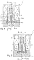
- the illustrated diaphragm valves 1 differ from each other in the structure of their valve seat 47th Die Ventilsitz 47 according to the embodiment of FIGS. 1 to 6 is web-like and therefore hereinafter referred to as web-like valve seat 47a.
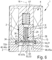
- Each valve seat 47 of the embodiment of FIGS. 7 to 11 and the FIG. 12 is ring-shaped closed in itself and will therefore hereinafter also referred to as annular valve seat 47b.
- the web-like valve seat 47a extends in the valve chamber 7 transversely to the height direction 16 between itself in particular diametrically opposite lateral wall portions 22a, 22b of the side wall 22. In this way, the valve chamber 7 is divided by the web-like valve seat 47a in two chamber sections 52a, 52b which each one of the two channel mouth 46a, 46b is located.
- the web-like valve seat 47a has a FIG. 5 easily recognizable linear longitudinal extent.
- first channel opening 46a is framed by an annular valve seat 47b, which is preferably raised like a collar on the bottom surface 23 and protrudes upward from there in the height direction 16 in the direction of the sealing membrane 8.
- the sealing membrane 8 extends across the valve seat 47 in all embodiments. It has in a valve seat 47 in the height direction 16 opposite Area over a sealing portion 53, which is the base 38 in the height direction 16 upstream and which in the execution of the switching movement 26 depending on the direction of movement through the membrane support 6 to the associated valve seat 47 fluidly pressed or lifted from the valve seat 47. In the closed position of the valve member 3, the sealing portion 53 sealingly abuts the associated valve seat 47, while it is lifted in the open position of the valve member 3 of this valve seat 47.
- the sealing portion 53 is that portion of the sealing membrane 8, which can be brought to bear on the associated valve seat 47. Its shape therefore corresponds to that of the valve seat 47. Accordingly, the sealing portion 53 of the FIGS. 1 to 6 to a strip-shaped sealing portion 53 a and in the embodiments of the FIGS. 7 to 12 around an annular sealing portion 53b. Each sealing portion 53 is opposite to the valve seat 47 in the height direction 16.
- annular valve seat 47b is expediently wholly within the outer contour 54 of the sealing membrane 8 facing base 38 of the membrane support 6.
- This base 38 is formed in both embodiments of an axially oriented end face of the membrane support 6, which is preferably designed plunger-like.
- a web-like valve seat 47a it is according to FIGS. 1 to 6 advantageous if the web-like valve seat 47a is covered at least approximately over its entire length by the base 38 of the membrane carrier 6.
- the outer edge region 14 fixed to the valve housing 2 and the attachment membrane section 36 of the sealing membrane 8 are transversal arranged at a distance from one another to the height direction 16.
- the outer edge region 14 surrounds the attachment membrane portion 36 all around in the manner of a self-contained frame.
- the sealing membrane 8 furthermore has a special membrane section, which will be referred to below as a loose membrane section 55.
- This loose membrane portion 55 extends between the attachment membrane portion 36 and the outer edge region 14, wherein it is not attached to the membrane support 6 - except for the attachment membrane portion 36 - and the base 38 is loosely upstream. The only, a fixing effecting connection between the sealing membrane 8 and the membrane support 6 thus results through the attachment membrane portion 36. While this attachment membrane portion 36 directly participates the switching movement of the membrane support 6, the loose membrane portion 55 is able to from the Base surface 38 lift off when the diaphragm support 6 moves from the closed position to the open position and thereby removed from the valve seat 47.
- the sealing portion 53 is at least partially part of the loose membrane portion 55.
- the sealing portion 53 is at least partially lifted from the base 38 in the direction of the switching movement 26.
- the loose membrane portion 55 component of the sealing portion 53 which is also referred to below as unfixed component 32 of the sealing portion 53, therefore applies that it is supported in the closed position of the valve member 3 of the base 38 of the diaphragm support 6 and the valve seat 47th is pressed while it is lifted in the open position of the valve member 3 both from the valve seat 47 and in an advantageous manner from the base 38 of the membrane carrier 6.
- the membrane valve 1 can be designed so that only a portion of the sealing portion 53 forms a part of the loose membrane portion 55.
- the strip-shaped sealing section 53a here extends partly over the fastening membrane section 36 and partly over the loose membrane section 55. Accordingly, the sealing section 53 has one of the fastening membrane section 36 formed fixed component 33 and at least one of the loose membrane portion 55 formed unfixed component 32. In the embodiment in which the strip-shaped sealing portion 53a extends diametrically across the base 38 away, therefore, only the two unfixed components 32 of the sealing portion 53 fold away from the membrane support 6.
- the diaphragm valve 1 can also be designed such that the sealing section 53 in its entirety is a component of the loose diaphragm section 55. This is in the embodiments of FIGS. 7 to 12 the case.
- the here annular-shaped sealing portion 53, 53b extends at a transverse distance and in particular at a radial distance to the attachment membrane portion 36 around this attachment membrane portion 36 around, so that it can completely lift off from the base 38 of the membrane support 6, if this at his Shifting movement 26 away from the annular valve seat 47b.
- the loose membrane portion 55 expediently contains, viewed in the height direction 16, the outer contour 54 of the base surface 38 surrounding the surrounding membrane outer portion 56, which merges into the outer edge region 14.
- the embodiments of the FIGS. 7 to 12 show such an embodiment. Since this membrane outer portion 56 is not covered by the membrane support 6, he experiences through the membrane support 6 no support against the pressure prevailing in the valve chamber 7 fluid pressure. However, so that the membrane outer portion 56 does not experience excessive stress even at high fluid pressures, it is expediently covered on its upper side facing away from the valve chamber 7 by a support wall 48 of the valve housing 2 unfolding a supporting action with respect to the outer membrane portion 56.
- the support wall It protrudes from the outer edge region 14 facing the outer side over the sealing membrane 8 away and preferably extends into the immediate vicinity of the membrane support 6, which expediently passes through a wall opening 44 of the support wall 48 slidably linearly ,
- the axial support of the membrane outer portion 56 is possible without functional impairment of the valve member 3, because the sealing membrane 8 in the region of the loose membrane portion 55 has the necessary freedom of movement to ensure the lifting movement of the membrane support 6 including the associated sealing portion 53.
- the diaphragm valve 1 can also be designed such that the outer edge region 14 fixed to the valve housing 2 adjoins the component of the sealing membrane 8 extending to the outer contour 54 directly. This applies to the embodiment of FIGS. 1 to 6 to.
- the diaphragm body 5 covers with its base 38 the entire cross-sectional area of the valve chamber 7.
- the sealing membrane 8 Due to the given for the loose membrane portion 55 possibility to stand out from the membrane support 6 or fold away from the membrane support 6 or fold away, there is the advantageous possibility to realize the sealing membrane 8 as a whole with a planar structure without bulges.
- the best example of this is the design of the FIGS. 1 to 6 in which the sealing membrane 8 with the exception of the fixing bead 21 has a planar shape with a substantially constant wall thickness.
- the sealing membrane 8, in particular in the region of the outer contour 54 of the membrane carrier 6, a viewed in the height direction 16 preferably have annular deformation portion 60 which has at least one bulge.
- existing electric drive means 4 expediently each include a spring device 57, which is supported between the valve housing 2 and the membrane support 6 and constantly acting in such an oppressive manner on the membrane support 6 that selbiger is biased in the above-mentioned closed position.
- This closed position thus defines the basic position of the diaphragm valve 1 in both embodiments.
- the drive means 4 in particular include a schematically indicated electromagnetic device 58, which contains an electromagnetically drivable drive member 63, which is formed by an electromagnetically driven armature of the solenoid device 58.
- This anchor is in the embodiments of FIGS. 1 to 11 formed in unit with the membrane carrier 6.
- the solenoid device 58 Upon activation of the solenoid device 58, a magnetic force is generated, which moves the membrane support 6, overcoming the restoring force of the spring device 57 in the open position.
- the spring device 57 is expediently a component of the electromagnetic device 58.
- the drive means 4 may also be of a different type than the one described.
- the diaphragm valve 1 is a single membrane body 5 functionally divided into two sealing membranes 8, which are each connected to a separate membrane support 6, so that they can cooperate with their own valve seat 47, 47b.
- Both membrane supports 6 are expediently formed plunger-like and guided parallel to each other linearly movable, wherein they are drivingly coupled to each other, that approximates a membrane support 6 to its associated valve seat 47, 47b, when the other membrane support 6 of the associated valve seat 47th , 47b is lifted.
- the drive-like coupling can be realized in particular by means of a rocker-like pivotable actuating lever 62, which can be driven by the drive means 4 to a reciprocating pivoting movement 65 and which has two drive arms 67, 68, which cooperate with one of the two membrane carrier 6.
- the pivotal movement 65 of the actuating lever 62 is converted into the linear switching movement of the two membrane carrier 6.
- FIG. 12 is different from the one of FIGS. 7 to 11 in particular by an additional third fluid channel 45c, which opens into the valve chamber 7 via a third channel opening 46c, which, like the first channel opening 46a, is assigned a valve seat 47, which in turn is an annular valve seat 47b.
- each of these annular valve seats 47b is opposite one of the two membrane supports 6, on each of which one of the two sealing membranes 8, ie in each case a membrane section of the membrane body, extends over each of these two valve seats 74b 5, in the same manner in the region of a membrane-mounting portion 36 is attached as in the embodiment of FIGS. 7 to 11 , It can be said that in the embodiment of the FIG. 12 the basis of the FIGS.
- the second fluid passage 45b is alternately connectable with either the first fluid passage 45a or the third fluid passage 45c and simultaneously separable from the other fluid passage 45c and 45a, respectively.
- the drive means 4 also included in the embodiment of FIG. 12 electrically actuatable drive means 4, which expediently include a schematically indicated electromagnetic device 58 with an electromagnetically drivable drive member 63.
- the drive member 63 exerts a pivoting movement 65 causing driving force on the actuating lever 62, wherein it has expediently overcome a restoring force of a spring device 57.
- pivot bearing means are visible, through which the actuating lever 62 is pivotally mounted relative to the valve housing 2 to enable the pivoting movement 65.
- the membrane carrier 6 is integrally formed.
- the sealing membrane 8 can be mounted on a multi-part membrane carrier in such a way that it is inserted into the membrane carrier and then fixed with a sleeve which at the same time forms a storage means for an axle shaft serving for the pivotable mounting of the membrane carrier.
- the sealing membrane 8 or the membrane body 5 can also be fixed by clamping between two parts of the membrane carrier 6.
Landscapes
- Engineering & Computer Science (AREA)
- General Engineering & Computer Science (AREA)
- Mechanical Engineering (AREA)
- Fluid-Driven Valves (AREA)
- Reciprocating Pumps (AREA)
Description
Die Erfindung betrifft ein Membranventil, mit einem Ventilgehäuse und mindestens einem diesbezüglich beweglichen Ventilglied, wobei das Ventilglied über einen unter Ausführung einer Umschaltbewegung relativ zum Ventilgehäuse bewegbaren Membranträger und über eine gemeinsam mit dem Ventilgehäuse eine Ventilkammer begrenzende flexible Dichtmembran verfügt, wobei die Dichtmembran an ihrem äußeren Randbereich unter Abdichtung an dem Ventilgehäuse fixiert ist und einen mit Abstand dazu an dem Membranträger befestigten und dessen Umschaltbewegung mitmachenden Befestigungs-Membranabschnitt aufweist, wobei in der Ventilkammer ein der Dichtmembran zugewandter Ventilsitz angeordnet ist, an den ein zumindest partiell von einer der Ventilkammer zugewandten Grundfläche des Membranträgers abgestützter Dichtabschnitt der Dichtmembran dichtend andrückbar ist, um wenigstens zwei in die Ventilkammer einmündende Fluidkanäle voneinander abzutrennen, wobei das Membranventil einen Membrankörper enthält, der funktionell in zwei Dichtmembranen eingeteilt ist, die jeweils mit einem eigenen Membranträger verbunden sind und die mit jeweils einem eigenen Ventilsitz kooperieren können, wobei die beiden Membranträger stößelartig ausgebildet und unter Ausführung einer linearen Umschaltbewegung parallel zueinander linear bewegbar sind und wobei die beiden Membranträger außerdem mittels eines wippenartig verschwenkbaren Betätigungshebels derart antriebsmäßig miteinander gekoppelt sind, dass sich der eine Membranträger an den ihm zugeordneten Ventilsitz annähert, wenn der andere Membranträger von dem ihm zugeordneten Ventilsitz abgehoben wird, wobei der Betätigungshebel durch elektrisch betätigbare Antriebsmittel des Membranventils zu einer hin- und hergehenden Schwenkbewegung antreibbar ist und über zwei Antriebsarme verfügt, die mit jeweils einem der beiden Membranträger kooperieren, sodass die Schwenkbewegung des Betätigungshebels in die lineare Umschaltbewegung der beiden Membranträger umgewandelt wird. Ein aus der
Aus der
Die
Bei einem aus der
Ein aus der
Die
Weitere Bauarten von Membranventilen sind aus
Der Erfindung liegt die Aufgabe zugrunde, ein Membranventil zu schaffen, dessen Dichtmembran zu Gunsten einer hohen Lebensdauer einer geringen Beanspruchung unterliegt.
Zur Lösung dieser Aufgabe ist in Verbindung mit den eingangs genannten Merkmalen vorgesehen, dass der Dichtabschnitt zumindest partiell Bestandteil eines losen Membranabschnittes der Dichtmembran ist, der sich, ohne am Membranträger befestigt zu sein, ausgehend von dem Befestigungs -Membranabschnitt bis zu dem am Ventilgehäuse fixierten äußeren Randbereich der Dichtmembran erstreckt, so dass er von der Grundfläche des Membranträgers abhebt, wenn der Membranträger sich bei seiner Umschaltbewegung von dem Ventilsitz entfernt. Auf diese Weise wird zum Abtrennen der Fluidverbindung zweier Fluidkanäle weiterhin ein Dichtabschnitt der Dichtmembran durch den die Dichtmembran tragenden Membranträger unter Abdichtung an einen zugeordneten Ventilsitz angedrückt. Dadurch ist auch bei einem hohen Fluiddruck einem unerwünschten Abheben des Dichtabschnittes vom Ventilsitz entgegengewirkt und für eine hohe Abdichtqualität gesorgt. Gleichwohl unterliegt die Dichtmembran selbst dann nur einer geringen Dehnung, wenn der Dichtabschnitt durch entsprechende Umschaltbewegung des Membranträgers vom zugeordneten Ventilsitz abgehoben wird. Ursache dafür ist, dass zumindest ein Teilbereich des Dichtabschnittes zu einem Membranabschnitt der Dichtmembran gehört, der sich zwischen dem Befestigungs-Membranabschnitt und dem am Ventilgehäuse fixierten äußeren Randbereich der Dichtmembran in am Membranträger nicht befestigter Weise erstreckt und deshalb in der Lage ist, sich von der Grundfläche des Membranträgers zu lösen, wenn sich der Membranträger bei seiner Umschaltbewegung vom zugeordneten Ventilsitz entfernt. Dieser nicht fixierte Membranabschnitt wird als loser Membranabschnitt bezeichnet. Während der Dichtabschnitt also zum fluiddichten Zusammenwirken mit dem Ventilsitz durch den Membranträger mechanisch abstützbar ist, hat zumindest ein Teilbereich des Dichtabschnittes die Möglichkeit, von der zuvor noch an ihm anliegenden Grundfläche des Membranträgers abzuheben beziehungsweise sich von dieser Grundfläche abzulösen, wenn der Membranträger zum Zwecke des Freigebens einer Fluidverbindung im Sinne eines sich von dem Ventilsitz Entfernens bewegt wird. Es kann sich hier insbesondere ein Verhaltensmuster ergeben, das man mit einem Abklappen beziehungsweise mit einem Wegklappen des losen Membranabschnittes vom Membranträger beschreiben könnte. Es kann sich dabei insbesondere ein zum Rand der Grundfläche hin keilförmig erweiternder Spalt zwischen dem losen Membranabschnitt und dem Membranträger auftun. Da die Dichtmembran in den vom Membranträger abhebbaren Bereichen nicht gezwungen ist, die Umschaltbewegung des Membranträgers in vollem Umfang mitzumachen, unterliegt sie einer verhältnismäßig geringen Dehnungsbeanspruchung. Die Folge ist eine hohe Lebensdauer des Membranventils verbunden mit der Möglichkeit, das Membranventil mit kompakten Abmessungen zu realisieren. Dadurch, dass sich ein zumindest einen Teil des Dichtabschnittes enthaltender Bestandteil der Dichtmembran vom Membranträger ablösen kann, ist die Voraussetzung geschaffen, eine Dichtmembran einzusetzen, die neben dem Membranträger keines besonderen Verformungsfreiraumes im Ventilgehäuse bedarf.
Das Membranventil ist mit elektrisch betätigbaren Antriebsmitteln ausgestattet, die zur Betätigung des Ventilgliedes dienen und die es ermöglichen, die Membranträger nach Bedarf zu ihrer Umschaltbewegung anzutreiben und in der jeweils gewünschten Position auch festzuhalten. Derartige Antriebsmittel enthalten vorzugsweise mindestens eine Elektromagneteinrichtung und vorzugsweise auch mindestens eine eine gewünschte Grundstellung vorgebende Rückstellfedereinrichtung. Vorteilhafte Weiterbildungen der Erfindung gehen aus den Unteransprüchen hervor. Die Umschaltbewegung des Membranträges ist eine Linearbewegung. Ein solcher Membranträger ist stößelartig ausgebildet und verfügt insbesondere über eine der Dichtmembran zugewandte axiale Stirnfläche, die die zur Abstützung des Dichtabschnittes dienende Grundfläche bildet.Other types of diaphragm valves are out
The invention has for its object to provide a diaphragm valve, the sealing membrane is subject to a low life in favor of a long service life.
To achieve this object is provided in connection with the features mentioned above, that the sealing portion is at least partially part of a loose membrane portion of the sealing membrane, which, without being attached to the membrane carrier, starting from the mounting diaphragm section to the fixed to the valve housing outer Edge region of the sealing membrane extends so that it lifts off from the base surface of the membrane carrier, when the membrane carrier moves away during its switching movement of the valve seat. In this way, to separate the fluid connection between two fluid channels, a sealing section of the sealing membrane is further pressed by the membrane membrane-carrying membrane carrier under sealing against an associated valve seat. As a result, undesired lifting of the sealing section from the valve seat is counteracted even at a high fluid pressure and ensures a high sealing quality. Nevertheless, the sealing membrane is subject to only a slight elongation even when the sealing portion is lifted by appropriate switching movement of the membrane carrier from the associated valve seat. The reason for this is that at least a portion of the sealing portion belongs to a membrane portion of the sealing membrane which extends between the attachment membrane portion and the valve housing fixed to the outer edge region of the sealing membrane in the membrane carrier not fixed manner and therefore is able to move away from the Base surface of the membrane carrier to solve when the membrane carrier moves away during its switching movement of the associated valve seat. This unfixed membrane section is referred to as a loose membrane section. While the sealing portion is thus mechanically supportable for fluid-tight interaction with the valve seat through the membrane carrier, at least a portion of the sealing portion has the ability to withdraw from the previously still resting on him base of the membrane support or detach from this base, if the membrane support for the purpose of Releasing a fluid connection in the sense of being moved away from the valve seat. In particular, a behavioral pattern can result here, which can be achieved by folding away or by folding away the loose membrane section could describe from the membrane carrier. In particular, a wedge-shaped widening gap between the loose membrane section and the membrane carrier can open up towards the edge of the base surface. Since the sealing membrane in the liftable from the membrane carrier areas is not forced to join the switching movement of the membrane carrier in full, it is subject to a relatively low strain. The result is a long service life of the diaphragm valve combined with the possibility of realizing the diaphragm valve with compact dimensions. The fact that a component of the sealing membrane containing at least part of the sealing section can come off the membrane carrier creates the prerequisite for using a sealing membrane which requires no special deformation clearance in the valve housing in addition to the membrane carrier.
The diaphragm valve is equipped with electrically actuatable drive means which serve to actuate the valve member and which make it possible to drive the membrane carrier as needed to their switching movement and also to hold in the desired position. Such drive means preferably contain at least one electromagnetic device and preferably also at least one return spring device which predetermines a desired basic position. Advantageous developments of the invention will become apparent from the dependent claims. The switching movement of the membrane support is a linear movement. Such a membrane carrier is formed plunger-like and has in particular one of the sealing membrane facing axial end face, which forms the base surface serving to support the sealing section.
Vorzugsweise ist die Dichtmembran mit ihrem Befestigungs-Membranabschnitt derart im Bereich der Grundfläche des Membranträgers befestigt, dass rings um den Befestigungs-Membranabschnitt ein radialer Abstand zwischen diesem Befestigungs-Membranabschnitt und dem Umriss der Grundfläche des Membranträgers vorliegt. Der sich zwischen dem Befestigungs-Membranabschnitt und dem Umriss der Grundfläche befindliche Bereich der Dichtmembran ist ein Bestandteil des losen Membranabschnittes. Der Befestigungs-Membranabschnitt ist insbesondere mittig im Bereich der Grundfläche angeordnet. Besonders zweckmäßig ist eine Ausgestaltung, bei der der lose Membranabschnitt den Befestigungs-Membranabschnitt in einem Bereich, der der Grundfläche vorgelagert ist, ringsum umrahmt. Auf diese Weise ergibt sich insbesondere ein ringförmiger Bereich des losen Membranabschnittes, der bei der Umschaltbewegung des Membranträgers relativ zum Membranträger beweglich ist, um nicht gezwungen zu sein, der Umschaltbewegung des Membranträgers in vollem Umfang zu folgen und dadurch einer hohen Dehnungsbelastung ausgesetzt zu sein.Preferably, the sealing membrane is fastened with its attachment membrane portion in the region of the base surface of the membrane carrier such that there is a radial distance between this attachment membrane portion and the outline of the base area of the membrane carrier around the attachment membrane portion. The area of the sealing membrane located between the fastening membrane section and the outline of the base area is a component of the loose membrane section. The attachment membrane section is arranged in particular centrally in the region of the base surface. Particularly useful is an embodiment in which the loose membrane portion surrounds the attachment membrane portion in an area which is upstream of the base, all around. In this way, in particular results in an annular region of the loose membrane portion which is movable in the switching movement of the membrane carrier relative to the membrane carrier in order not to be forced to follow the switching movement of the membrane carrier in full and thereby exposed to a high strain load.
In einer bevorzugten Ausgestaltung ist der Ventilsitz des Membranventils ringförmig in sich geschlossen ausgebildet, so dass er die Kanalmündung eines Fluidkanals umrahmt. Zum Absperren dieses Fluidkanals liegt mithin ein ebenfalls ringförmiger Dichtabschnitt der Dichtmembran an dem Ventilsitz an. Von diesem ringförmigen Dichtabschnitt ist zumindest ein Teilbereich als Bestandteil des losen Membranabschnittes ausgebildet, so dass er vom Membranträger abheben kann, wenn selbiger zum Freigeben des Fluidkanals von dem Ventilsitz wegbewegt wird.In a preferred embodiment, the valve seat of the diaphragm valve is formed annularly closed in itself, so that it framed the channel mouth of a fluid channel. To shut off this fluid channel is therefore also a ring-shaped sealing portion of the sealing membrane on the valve seat. Of this annular sealing portion at least a portion is formed as part of the loose membrane portion, so that it can lift off from the membrane carrier, when selbiger is moved away to release the fluid channel of the valve seat.
Vorzugsweise ist die Dichtmembran so ausgebildet, dass ein mit einem ringförmigen Ventilsitz kooperierender ringförmiger Dichtabschnitt in seiner Gesamtheit ein Bestandteil des losen Membranabschnittes ist, so dass er zur Gänze von der Grundfläche des Membranträgers abheben kann, wenn sich der Membranträger bei der Umschaltbewegung von dem Ventilsitz entfernt. Grundsätzlich ist allerdings auch eine Bauform möglich, bei der der mit dem Ventilsitz kooperierende Dichtabschnitt teilweise ein Bestandteil des Befestigungs-Membranabschnittes und nur teilweise ein Bestandteil des losen Membranabschnittes ist.Preferably, the sealing membrane is formed so that a cooperating with an annular valve seat annular sealing portion in its entirety is a part of the loose membrane portion, so that it can lift off completely from the base of the membrane carrier, when the membrane carrier in the switching movement away from the valve seat , Basically, however, a design is possible in which the cooperating with the valve seat sealing portion is partially a part of the attachment membrane portion and only partially a part of the loose membrane portion.
In einer Draufsicht auf die Grundfläche des Membranträgers betrachtet, liegt der Dichtabschnitt zweckmäßigerweise vollständig innerhalb des äußeren Umrisses der Grundfläche des Membranträgers.Viewed in a plan view of the base of the membrane carrier, the sealing portion is expediently completely within the outer contour of the base of the membrane carrier.
Bei einer ebenfalls vorteilhaften Ausgestaltung des Membranventils ist der Ventilsitz stegartig ausgebildet und erstreckt sich derart zwischen zwei sich gegenüberliegenden seitlichen Wandabschnitten der Ventilkammer, dass er diese Ventilkammer in zwei diesseits und jenseits des stegartigen Ventilsitzes liegende Kammerabschnitte unterteilt. Der in diesem Fall streifenförmig ausgebildete Dichtabschnitt gehört zumindest teilweise zu dem losen Membranabschnitt. Insbesondere ist eine Bauform vorgesehen, bei der der Dichtabschnitt teilweise von dem Befestigungs-Membranabschnitt gebildet ist, so dass er nur partiell von der Grundfläche des Membranträgers abheben kann. Der Dichtabschnitt hat zweckmäßigerweise zwei von dem Membranträger abhebbare Bereiche, die den Befestigungs-Membranabschnitt auf entgegengesetzten Seiten flankieren.In a likewise advantageous embodiment of the diaphragm valve, the valve seat is web-like and extends between two opposite lateral wall sections of the valve chamber, that it subdivides this valve chamber in two lying on this side and beyond the web-like valve seat chamber sections. The sealing portion which is strip-shaped in this case belongs at least partially to the loose membrane portion. In particular, a design is provided in which the sealing portion is partially formed by the attachment membrane portion, so that it can only partially lift off from the base of the membrane carrier. The sealing section expediently has two areas which can be lifted off from the membrane carrier and which flank the fastening membrane section on opposite sides.
Vorzugsweise ist die Dichtmembran im Bereich des Befestigungs-Membranabschnittes ausschließlich im Innern des Membranträgers befestigt. Insbesondere in diesem Zusammenhang ist es von Vorteil, wenn die Dichtmembran Bestandteil eines einstückigen Membrankörpers ist, der im Bereich des Befestigungs-Membranabschnittes mindestens einen und vorzugsweise genau einen ausgehend von der Grundfläche in den Membranträger eingreifenden Befestigungsfortsatz aufweist. Dort, wo der Befestigungsfortsatz in den Membranträger eingreift, weist die Grundfläche eine Öffnung auf, wobei die Grundfläche insbesondere ringförmig und vorzugsweise kreisringförmig gestaltet ist.Preferably, the sealing membrane is fastened in the region of the attachment membrane section exclusively in the interior of the membrane carrier. In particular, in this context, it is advantageous if the sealing membrane is part of a one-piece membrane body having at least one and preferably exactly one starting from the base in the membrane carrier engaging fastening extension in the region of the attachment membrane portion. Where the fastening extension engages in the membrane carrier, the base surface has an opening, wherein the base surface is designed in particular ring-shaped and preferably annular.
Die Befestigung der Dichtmembran im Innern des Membranträgers erfolgt insbesondere ausschließlich auf der Grundlage von Formschluss und/oder Kraftschluss. Beispielsweise kann ein Membrankörper bei seiner Herstellung im Rahmen eines Spritzgießverfahrens an den Membranträger angeformt werden, wobei ein in den Membranträger eingreifender Befestigungsfortsatz ausgebildet wird. Es besteht allerdings ohne weiteres die Möglichkeit, den Befestigungs-Membranabschnitt alternativ oder zusätzlich durch Stoffschluss am Membranträger zu fixieren, beispielsweise im Rahmen einer Klebeverbindung.The attachment of the sealing membrane in the interior of the membrane carrier takes place in particular exclusively on the basis of positive engagement and / or adhesion. For example, a membrane body can be molded onto the membrane carrier during its production by means of an injection molding process, wherein an attachment extension engaging in the membrane carrier is formed. However, it is readily possible to fix the attachment membrane portion alternatively or additionally by material bond on the membrane support, for example in the context of an adhesive bond.
Die Dichtmembran ist vorzugsweise so gestaltet, dass sie entlang des äußeren Umrisses der Grundfläche des Membranträgers ringsum über den Membranträger hinausragt und einen die Grundfläche außen umrahmenden Membran-Außenabschnitt aufweist, der in den am Ventilgehäuse unter Abdichtung fixierten äußeren Randbereich übergeht. Dieser Membran-Außenabschnitt ist zweckmäßigerweise an seiner der Ventilkammer abgewandten Oberseite von einer Abstützwand des Ventilgehäuses abgedeckt, so dass er auch hohen in der Ventilkammer herrschenden Fluiddrücken standhalten kann. Die Abstützwand hat zweckmäßigerweise eine Durchbrechung, durch die der Membranträger in einer die Umschaltbewegung gestattenden Weise hindurchragt, wobei der Vorteil besteht, dass das Spaltmaß zwischen dem Membranträger und der Abstützwand sehr gering gehalten werden kann.The sealing membrane is preferably designed so that it extends along the outer contour of the base of the membrane support all around the membrane support and having a base outside framing membrane outer portion which merges into the valve housing to seal fixed outer edge region. This membrane outer portion is expediently covered on its upper side facing away from the valve chamber by a support wall of the valve housing, so that it can withstand high fluid pressures prevailing in the valve chamber. The support wall has expediently an aperture through which the membrane carrier projects in a manner permitting the switching movement, with the advantage that the gap between the membrane carrier and the supporting wall can be kept very low.
Die Ventilkammer und die die Ventilkammer verschließende Dichtmembran haben insbesondere eine Längsgestalt mit schmalseitig abgerundetem Umriss oder verfügen zweckmäßigerweise über einen runden Umriss. In der Ventilkammer sind die vorhandenen Kanalmündungen der einmündenden Fluidkanäle vorzugsweise nebeneinander angeordnet, wobei sie bei einer länglichen Ventilkammer insbesondere in der Längsrichtung dieser Ventilkammer mit Abstand aufeinanderfolgend angeordnet sind.The valve chamber and the sealing chamber closing the valve chamber have in particular a longitudinal shape with a narrow-side rounded outline or expediently have a round outline. In the valve chamber, the existing channel openings of the opening fluid channels are preferably arranged side by side, wherein they are arranged at an elongated valve chamber, in particular in the longitudinal direction of the valve chamber at a distance successively.
Nachfolgend wird die Erfindung anhand der beiliegenden Zeichnung näher erläutert. In dieser zeigen:
Figur 1- einen Längsschnitt durch eine Ausführungsform eines nicht erfindungsgemäßen Membranventils gemäß Schnittlinie I-I aus
Figuren 2 und3 , das über einen stegartigen Ventilsitz verfügt, wobei eine Schließstellung gezeigt ist, Figur 2- das
Membranventil aus Figur 1 ineinem bezüglich Figur 1 um 90° verdrehten Längsschnitt gemäß Schnittlinie II-II aus Figuren 1 und3 , Figur 3- einen Querschnitt durch das Membranventil gemäß Schnittlinie III-
III aus Figur 1 , Figur 4- das
Membranventil der Figuren 1 in einer Offenstellung und in einer derbis 3Figur 1 entsprechenden Längsschnittdarstellung gemäß Schnittlinie IV-IV aus Figur 5 , Figur 5- das die Offenstellung einnehmende Membranventil in einem Längsschnitt gemäß Schnittlinie V-V aus
Figur 4 , Figur 6- den in
Figur 5 Figur 7- eine weitere Ausführungsform eines nicht erfindungsgemäßen Membranventils, dessen Ventilsitz ringförmig ausgebildet ist, wobei in einem Längsschnitt gemäß Schnittlinie VII-
VII aus Figuren 8 und9 eine Schließstellung gezeigt ist, Figur 8- das
Membranventil aus Figur 7 in einem um 90° verdrehten Längsschnitt gemäß Schnittlinie VIII-VIII aus Figuren 7 und9 , - Figur 9
- einen Querschnitt durch das
Membranventil der Figuren 7 und 8 gemäß Schnittlinie IX-IX aus Figur 7 , - Figur 10
- das
Membranventil der Figuren 7 bis 9 in einer Offenstellung und in einem derFigur 7 entsprechenden Längsschnitt gemäß Schnittlinie X-X ausFigur 11 , - Figur 11
- in einem Längsschnitt gemäß Schnittlinie XI-XI das
Membranventil der Figuren 7 bis 10 , wobei strichpunktiert eine bevorzugte Ausführungsform elektrisch betätigbarer Antriebsmittel für das Ventilglied illustriert ist, und Figur 12- eine Ausführungsform des erfindungsgemäßen Membranventils, das über zwei ringförmig ausgebildete Ventilsitze verfügt, in einer Schnittdarstellung analog zu
Figur 7
- FIG. 1
- a longitudinal section through an embodiment of a non-inventive diaphragm valve according to section line II
Figures 2 and3 , which has a web-like valve seat, wherein a closed position is shown, - FIG. 2
- the diaphragm valve off
FIG. 1 in a respectFIG. 1 90 ° twisted longitudinal section according to section line II-IIFIGS. 1 and3 . - FIG. 3
- a cross section through the diaphragm valve according to section line III-III
FIG. 1 . - FIG. 4
- the diaphragm valve the
FIGS. 1 to 3 in an open position and in one of theFIG. 1 appropriate Longitudinal view according to section line IV-IVFIG. 5 . - FIG. 5
- the diaphragm valve occupying the open position in a longitudinal section according to section line VV
FIG. 4 . - FIG. 6
- the in
FIG. 5 illustrated longitudinal section with an isometric perspective, - FIG. 7
- a further embodiment of a non-inventive diaphragm valve whose valve seat is annular, wherein in a longitudinal section along line VII-VII of
FIGS. 8 and9 a closed position is shown - FIG. 8
- the diaphragm valve off
FIG. 7 in a 90 ° twisted longitudinal section according to section line VIII-VIIIFIGS. 7 and9 . - FIG. 9
- a cross section through the diaphragm valve of
FIGS. 7 and 8 according to section line IX-IXFIG. 7 . - FIG. 10
- the diaphragm valve the
FIGS. 7 to 9 in an open position and in one ofFIG. 7 corresponding longitudinal section according to section line XXFIG. 11 . - FIG. 11
- in a longitudinal section along section line XI-XI, the diaphragm valve of
FIGS. 7 to 10 , wherein dash-dotted lines a preferred embodiment of electrically actuable drive means for the valve member is illustrated, and - FIG. 12
- an embodiment of the diaphragm valve according to the invention, which has two ring-shaped valve seats, in a sectional view analogous to
FIG. 7 ,
Das in seiner Gesamtheit mit Bezugsziffer 1 bezeichnete Membranventil verfügt bei allen Ausführungsbeispielen über ein Ventilgehäuse 2 und ein in dem Ventilgehäuse 2 angeordnetes, relativ zum Ventilgehäuse 2 bewegliches Ventilglied 3. Darüber hinaus ist das Membranventil 1 mit bevorzugt im Innern des Ventilgehäuses 2 untergebrachten, elektrisch betätigbaren Antriebsmitteln 4 ausgestattet, durch die das Ventilglied 3 zwischen zwei möglichen Schaltstellung umschaltbar ist. Die
Das Ventilglied 3 ist bevorzugt als Verbundelement ausgebildet, das sich aus einem Membrankörper 5 und mindestens einem den Membrankörper 5 tragenden Membranträger 6 zusammensetzt. Diese Komponenten sind in einer noch zu erläuternden Weise aneinander befestigt. Während der Membranträger 6 aus einem starren Material besteht, beispielsweise aus einem starren Kunststoffmaterial oder aus Metall, besteht der Membrankörper 5 aus einem flexiblen und vorzugsweise gummielastischen Material. Vorzugsweise handelt es sich bei dem Membrankörper 5 um einen Elastomerkörper.The
Im Innern des Ventilgehäuses 2 befindet sich ein eine Ventilkammer 7 bildender Hohlraum. Die Ventilkammer 7 ist einerseits vom Ventilgehäuse 2 und andererseits von einem als Dichtmembran 8 bezeichneten membranartigen Bestandteil des Membrankörpers 5 begrenzt.In the interior of the
Das Ventilgehäuse 2 definiert eine die Ventilkammer 7 an einer Unterseite begrenzende Bodenwand 12. Die Bodenwand 12 ist bevorzugt Bestandteil eines ersten Gehäuseteils 13 des Ventilgehäuses 2.The
Die Dichtmembran 8 hat flächenhafte Ausdehnung und erstreckt sich an einer Oberseite über die Bodenwand 12 hinweg. Mit einem den äußeren Umriss der Dichtmembran 8 definierenden äußeren Randbereich 14 ist die Dichtmembran 8 derart unter Abdichtung am Ventilgehäuse 2 fixiert, dass sie gemeinsam mit der Bodenwand 12 die zur Umgebung hin abgedichtete Ventilkammer 7 begrenzt.The sealing
Die fluiddichte Fixierung des äußeren Randbereiches 14 wird zweckmäßigerweise dadurch realisiert, dass dieser äußere Randbereich 14 zwischen dem ersten Gehäuseteil 13 und einem zweiten Gehäuseteil 15 des Ventilgehäuses 2 fest eingespannt ist. An dem äußeren Randbereich 14 weist die Dichtmembran 8 in diesem Zusammenhang zweckmäßigerweise einen den äußeren Umriss der Dichtmembran 8 bestimmenden Befestigungswulst 21 auf. Dieser greift in je eine Ringnut ein, die einander gegenüberliegend an den einander zugewandten Flächen des ersten und zweiten Gehäuseteils 13, 15 ausgebildet sind.The fluid-tight fixation of the outer edge region 14 is expediently realized in that this outer edge region 14 is firmly clamped between the first housing part 13 and a
Im Folgenden sei die Richtung, in der die Dichtmembran 8 der Bodenwand 12 gegenüberliegt, als Höhenrichtung 16 bezeichnet. Rechtwinkelig zu der Höhenrichtung 16 hat die Ventilkammer 7 eine Hauptachse 17 und eine hierzu rechtwinkelige Querachse 18. Beim Ausführungsbeispiel der
Seitlich ist jede Ventilkammer 7 von einer den oben erwähnten Umriss bestimmenden Seitenwand 22 begrenzt. Sie überragt nach oben hin eine der Dichtmembran 8 zugewandte Bodenfläche 23 der Ventilkammer 7, die an der Bodenwand 12 ausgebildet ist.Laterally, each
Der Membrankörper 5 verfügt über einen bevorzugt einstückig mit der Dichtmembran 8 ausgebildeten Befestigungsfortsatz 24, der in der Höhenrichtung 16 in Richtung zum Membranträger 6 wegragt. Mittels dieses Befestigungsfortsatzes 24 ist der Membrankörper 5 an dem Membranträger 6 befestigt. Beim Ausführungsbeispiel der
Der Membranträger 6 befindet sich auf der der Bodenwand 12 in der Höhenrichtung 16 entgegengesetzten Seite der Dichtmembran 8. Die Dichtmembran 8 liegt mithin in der Höhenrichtung 16 zwischen der Ventilkammer 7 und dem Membranträger 6.The
Bei allen Ausführungsbeispielen ist der Membranträger 6 bezüglich des Ventilgehäuses 2 linear bewegbar gelagert. Die von dem Membranträger 6 ausführbare Bewegung sei im Folgenden als Umschaltbewegung 26 bezeichnet, weil sie sich unmittelbar auf die Schaltstellung des Ventilgliedes 3 auswirkt. Die Umschaltbewegung 26 ist bevorzugt eine Linearbewegung und verläuft bei den Ausführungsbeispielen in der Höhenrichtung 16. Dementsprechend ist der Membranträger 6 unter Ausführung einer linearen Umschaltbewegung 26 in der Höhenrichtung 16 hin und her bewegbar. Hierbei findet je nach Bewegungsrichtung eine Annäherung an die Bodenwand 12 oder ein Entfernen von der Bodenwand 12 seitens des Membranträgers 6 statt.In all embodiments, the
Ein Abschnitt der Dichtmembran 8 macht die Umschaltbewegung 26 des Membranträgers 6 uneingeschränkt mit. Es handelt sich hier um einen im Folgenden als Befestigungs-Membranabschnitt 36 bezeichneten Membranabschnitt der Dichtmembran 8, über den die Dichtmembran 8 an dem Membranträger 6 befestigt ist.A portion of the sealing
Den Ausführungsbeispielen ist gemeinsam, dass die Dichtmembran 8 im Bereich des Befestigungs-Membranabschnittes 36 ausschließlich im Innern des Membranträgers 6 befestigt ist. Hierzu ist der Befestigungsfortsatz 24 direkt an dem Befestigungs-Membranabschnitt 36 angeordnet und greift von der Seite einer der Dichtmembran 8 zugewandten Grundfläche 38 des Membranträgers 6 her in eine zu der Grundfläche 38 hin offene Befestigungsaussparung 43 des Membranträgers 6 hinein. Die Grundfläche 38 ist vorzugsweise eben und erstreckt sich insbesondere rechtwinkelig zu der Höhenrichtung 16 und/oder der Richtung der Umschaltbewegung 26.The exemplary embodiments have in common that the sealing
Der Befestigungsfortsatz 24 ist in der Befestigungsaussparung 43 so fixiert, dass er die lineare Umschaltbewegung 26 des Membranträgers 6 direkt mitmacht. Dies gilt folglich auch für den direkt an dem Befestigungsfortsatz 24 angeordneten Befestigungs-Membranabschnitt 36, der außerhalb der Befestigungsaussparung 43 liegt. Bei beiden Ausführungsbeispielen ist der Befestigungs-Membranabschnitt 36 dem zentralen Bereich der Grundfläche 38 zugeordnet.The
Die Dichtmembran 8 ist zweckmäßigerweise ausschließlich im Bereich des Befestigungs-Membranabschnittes 36 an dem Membranträger 6 gehalten. Genauer gesagt ergibt sich die feste Verbindung aus dem Zusammenwirken zwischen dem Innenumfang der Befestigungsaussparung 43 und dem in die Befestigungsaussparung 43 eintauchenden Befestigungsfortsatz 24. Zwischen diesen beiden Komponenten liegt bei den Ausführungsbeispielen eine stoffschlüssige Verbindung vor, die mittels eines in der Zeichnung nicht ersichtlichen Klebstoffes realisiert ist. Zusätzlich oder alternativ ist aber auch eine kraftschlüssige Verbindung möglich. Weiterhin kann die Befestigungsaussparung 43 auch so konturiert sein, dass sie zusätzlich oder alternativ mit dem Befestigungsfortsatz 24 eine in der Höhenrichtung 16 formschlüssige Verbindung eingeht. Letzteres ist beispielsweise dadurch realisierbar, dass die Befestigungsaussparung 43 über mindestens eine Verengung verfügt, die in einen eingeschnürten oder taillierten Umfangsbereich des Befestigungsfortsatzes 24 in bezüglich der Höhenrichtung 16 radialer Richtung eingreift oder eindrückt.The sealing
In die Ventilkammer 7 münden mehrere das Ventilgehäuse 2 durchsetzende Fluidkanäle 45 ein. Bei den Ausführungsbeispielen der
Bei den Ausführungsbeispielen seien zwei Fluidkanäle 45 im Folgenden zur besseren Unterscheidung auch als erster und zweiter Fluidkanal 45a, 45b bezeichnet. Beide Fluidkanäle 45a, 45b durchsetzen zweckmäßigerweise die Bodenwand 12 und münden an der Bodenfläche 23 mit je einer Kanalmündung 46 in die Ventilkammer 7 ein. Zur besseren Unterscheidung seien auch hier die Kanalmündungen 46 als erste und zweite Kanalmündungen 46a, 46b bezeichnet.In the exemplary embodiments, two fluid channels 45 are also referred to below as the first and second fluid channels 45a, 45b for better distinction. Both fluid channels 45a, 45b suitably pass through the
Das Membranventil 1 kann bei den Ausführungsbeispielen der
Um diese Ventilfunktion ausüben zu können, kooperiert das Ventilglied 3 mit einem ortsfest bezüglich des Ventilgehäuses 2 angeordneten Ventilsitz 47. Die illustrierten Membranventile 1 unterscheiden sich voneinander in der Struktur ihres Ventilsitzes 47. Der Ventilsitz 47 gemäß Ausführungsbeispiel der
Der stegartige Ventilsitz 47a erstreckt sich in der Ventilkammer 7 quer zu der Höhenrichtung 16 zwischen sich insbesondere diametral gegenüberliegenden seitlichen Wandabschnitten 22a, 22b der Seitenwand 22. Auf diese Weise wird die Ventilkammer 7 durch den stegartigen Ventilsitz 47a in zwei Kammerabschnitte 52a, 52b unterteilt, in denen sich jeweils eine der beiden Kanalmündung 46a, 46b befindet. Bevorzugt hat der stegartige Ventilsitz 47a eine aus
Beim Ausführungsbeispiel der
Die Dichtmembran 8 erstreckt sich bei allen Ausführungsbeispielen über den Ventilsitz 47 hinweg. Dabei verfügt sie in einem dem Ventilsitz 47 in der Höhenrichtung 16 gegenüberliegenden Bereich über einen Dichtabschnitt 53, der der Grundfläche 38 in der Höhenrichtung 16 vorgelagert ist und der bei Ausführung der Umschaltbewegung 26 je nach Bewegungsrichtung durch den Membranträger 6 an den zugeordneten Ventilsitz 47 fluiddicht andrückbar oder von dem Ventilsitz 47 abhebbar ist. In der Schließstellung des Ventilgliedes 3 liegt der Dichtabschnitt 53 dichtend am zugeordneten Ventilsitz 47 an, während er in der Offenstellung des Ventilgliedes 3 von diesem Ventilsitz 47 abgehoben ist.The sealing
Der Dichtabschnitt 53 ist derjenige Teilbereich der Dichtmembran 8, der am zugeordneten Ventilsitz 47 zur Anlage bringbar ist. Seine Gestalt entspricht daher derjenigen des Ventilsitzes 47. Dementsprechend handelt es sich bei dem Dichtabschnitt 53 der
Beim Ausführungsbeispiel der
Der am Ventilgehäuse 2 fixierte äußere Randbereich 14 und der Befestigungs-Membranabschnitt 36 der Dichtmembran 8 sind quer zu der Höhenrichtung 16 mit Abstand zueinander angeordnet. Vorzugsweise umschließt der äußere Randbereich 14 den Befestigungs-Membranabschnitt 36 ringsum nach Art eines in sich geschlossenen Rahmens.The outer edge region 14 fixed to the
Die Dichtmembran 8 verfügt des Weiteren über einen besonderen Membranabschnitt, der im Folgenden als loser Membranabschnitt 55 bezeichnet sei. Dieser lose Membranabschnitt 55 erstreckt sich zwischen dem Befestigungs-Membranabschnitt 36 und dem äußeren Randbereich 14, wobei er an dem Membranträger 6 - abgesehen über den Befestigungs-Membranabschnitt 36 - nicht befestigt ist und der Grundfläche 38 lose vorgelagert ist. Die einzige, eine Fixierung bewirkende Verbindung zwischen der Dichtmembran 8 und dem Membranträger 6 ergibt sich also durch den Befestigungs-Membranabschnitt 36. Während dieser Befestigungs-Membranabschnitt 36 die Umschaltbewegung des Membranträgers 6 direkt mitmacht, ist der lose Membranabschnitt 55 in der Lage, von der Grundfläche 38 abzuheben, wenn sich der Membranträger 6 aus der Schließstellung in die Offenstellung bewegt und sich dabei vom Ventilsitz 47 entfernt. Der Dichtabschnitt 53 gehört zumindest zum Teil zu dem losen Membranabschnitt 55. Mithin ist auch der Dichtabschnitt 53 zumindest partiell von der Grundfläche 38 in der Richtung der Umschaltbewegung 26 abhebbar. Für den zum losen Membranabschnitt 55 gehörenden Bestandteil des Dichtabschnittes 53, der im Folgenden auch als unfixierter Bestandteil 32 des Dichtabschnittes 53 bezeichnet wird, gilt mithin, dass er in der Schließstellung des Ventilgliedes 3 von der Grundfläche 38 des Membranträgers 6 abgestützt und an den Ventilsitz 47 angedrückt wird, während er in der Offenstellung des Ventilgliedes 3 sowohl vom Ventilsitz 47 als auch in vorteilhafter Weise von der Grundfläche 38 des Membranträgers 6 abgehoben ist.The sealing
In den
Wenn der lose Membranabschnitt 55 von dem Membranträger 6 abhebt, entsteht zwischen diesen beiden Komponenten zweckmäßigerweise ein sich ausgehend von dem Befestigungsfortsatz 24 in Richtung zum Umriss 54 etwa keilförmig verbreiternder Spalt 34, der besonders gut in
Dadurch, dass die Dichtmembran 8 mit Ausnahme an dem Befestigungs-Membranabschnitt 36 an dem Membranträger 6 nicht befestigt ist, sind die sich an den Befestigungs-Membranabschnitt 36 anschließenden Bereiche der Dichtmembran 8, insbesondere der lose Membranabschnitt 55, nicht gezwungen, die Umschaltbewegung 26 des Membranträgers 6 in vollem Umfang mitzumachen, was die Dehnungsbelastung der Dichtmembran 8 reduziert und sich positiv auf die Lebensdauer auswirkt.Due to the fact that the sealing
Das Membranventil 1 kann so ausgebildet sein, dass lediglich ein Teilbereich des Dichtabschnittes 53 einen Bestandteil des losen Membranabschnittes 55 bildet. Exemplarisch trifft dies auf das Ausführungsbeispiel der
Das Membranventil 1 kann auch so ausgebildet sein, dass der Dichtabschnitt 53 in seiner Gesamtheit ein Bestandteil des losen Membranabschnittes 55 ist. Dies ist bei den Ausführungsbeispielen der
Der lose Membranabschnitt 55 enthält zweckmäßigerweise einen, in der Höhenrichtung 16 betrachtet, den äußeren Umriss 54 der Grundfläche 38 ringsum umrahmenden Membran-Außenabschnitt 56, der in den äußeren Randbereich 14 übergeht. Die Ausführungsbeispiele der
Die axiale Abstützung des Membran-Außenabschnittes 56 ist ohne Funktionsbeeinträchtigung des Ventilgliedes 3 möglich, weil die Dichtmembran 8 im Bereich des losen Membranabschnittes 55 den notwendigen Bewegungsspielraum aufweist, um die Hubbewegung des Membranträgers 6 einschließlich des zugeordneten Dichtabschnittes 53 zu gewährleisten.The axial support of the membrane
Das Membranventil 1 kann auch so ausgebildet sein, dass sich an den bis zum äußeren Umriss 54 reichenden Bestandteil der Dichtmembran 8 unmittelbar der am Ventilgehäuse 2 fixierte äußere Randbereich 14 anschließt. Dies trifft auf das Ausführungsbeispiel der
Aufgrund der für den losen Membranabschnitt 55 gegebenen Möglichkeit, sich von dem Membranträger 6 abzuheben beziehungsweise von dem Membranträger 6 abzuklappen oder wegzuklappen, besteht die vorteilhafte Möglichkeit, die Dichtmembran 8 insgesamt mit einer ebenen Struktur ohne Auswölbungen zu realisieren. Das beste Beispiel hierfür ist die Bauform der
Die bei den Ausführungsbeispielen der
Zum Umschalten in die Offenstellung enthalten die Antriebsmittel 4 insbesondere eine schematisch angedeutete Elektromagneteinrichtung 58, die ein elektromagnetisch antreibbares Antriebsglied 63 enthält, das von einem elektromagnetisch antreibbaren Anker der Elektromagneteinrichtung 58 gebildet ist. Dieser Anker ist bei den Ausführungsbeispielen der
Es versteht sich, dass die Antriebsmittel 4 auch von anderer Bauart als der geschilderten sein können.It is understood that the drive means 4 may also be of a different type than the one described.
Bei dem in
Beide Membranträger 6 sind hier zweckmäßigerweise stößelartig ausgebildet und parallel zueinander linear bewegbar geführt, wobei sie derart antriebsmäßig miteinander gekoppelt sind, dass sich der eine Membranträger 6 an den ihm zugeordneten Ventilsitz 47, 47b annähert, wenn der andere Membranträger 6 von dem ihm zugeordneten Ventilsitz 47, 47b abgehoben wird. Die antriebsmäßige Kopplung ist insbesondere mittels eines wippenartig verschwenkbaren Betätigungshebels 62 realisierbar, der durch die Antriebsmittel 4 zu einer hin- und hergehenden Schwenkbewegung 65 antreibbar ist und der über zwei Antriebsarme 67, 68 verfügt, die mit jeweils einem der beiden Membranträger 6 kooperieren. Somit wird bei dieser Ausführungsform die Schwenkbewegung 65 des Betätigungshebels 62 in die lineare Umschaltbewegung der beiden Membranträger 6 umgewandelt.Both membrane supports 6 are expediently formed plunger-like and guided parallel to each other linearly movable, wherein they are drivingly coupled to each other, that approximates a
Das Ausführungsbeispiel der
Somit ist beim Ausführungsbeispiel der
Bei 66 sind Schwenklagermittel ersichtlich, durch die der Betätigungshebel 62 bezüglich des Ventilgehäuses 2 zur Ermöglichung der Schwenkbewegung 65 verschwenkbar gelagert ist.
Im Übrigen sind in der
Abweichend von dem vorgenannten Ausführungsbeispiel können ein oder zwei Membranträger 6 auch feste Bestandteile eines insgesamt wippenartig verschwenkbaren Betätigungselementes sein.The embodiment of
Thus, in the embodiment of the
At 66 pivot bearing means are visible, through which the
Incidentally, in the
Deviating from the aforementioned embodiment, one or two
Bei den Ausführungsbeispielen ist der Membranträger 6 einstückig ausgebildet. Hiervon abweichend ist aber auch ein mehrteiliger und insbesondere zweiteiliger Aufbau möglich. So kann die Dichtmembran 8 beispielsweise derart an einem mehrteiligen Membranträger montiert werden, dass sie in den Membranträger eingeschoben wird und danach mit einer Hülse fixiert wird, die gleichzeitig ein Lagerungsmittel für eine zur schwenkbaren Lagerung des Membranträgers dienende Achswelle bildet. Die Dichtmembran 8 oder der Membrankörper 5 kann auch zwischen zwei Teilen des Membranträgers 6 durch Klemmung fixiert sein.In the embodiments, the
Claims (15)
- Diaphragm valve, comprising a valve housing (2) and at least one valve member (3) which is movable relative thereto, wherein the valve member (3) has a diaphragm support (6), which is movable relative to the valve housing (2) while performing a switch-over movement (26), and a flexible sealing diaphragm (8), which bounds a valve chamber (7) together with the valve housing (2), wherein the sealing diaphragm (8) is fixed to the valve housing (2) in its outer edge region (14) while forming a seal and comprises a fastening diaphragm section (36), which is secured to the diaphragm support (6) at a distance therefrom and participates in its switch-over movement (26), wherein in the valve chamber (7) there is located a valve seat (47), which faces the sealing diaphragm (8) and against which a sealing section (53) of the sealing diaphragm (8), which is at least partially supported by a base surface (38) - facing the valve chamber (7) - of the diaphragm support (6), can be pressed to form a seal in order to disconnect at least two fluid passages (45, 45a, 45b) terminating into the valve chamber (7) from one another, wherein the diaphragm valve (1) contains a diaphragm body (5), which is functionally divided into two sealing diaphragms (8), each of which is joined to its own diaphragm support (6) and capable of cooperating with its own valve seat (47), wherein the two diaphragm supports (6) are designed in the manner of plungers and movable in a linear motion parallel to each other while performing a linear switch-over movement (26), and wherein the two diaphragm supports (6) are furthermore drive-coupled to each other by means of an actuating lever (62) pivotable in the manner of a rocker in such a way that the one diaphragm support (6) approaches the associated valve seat (47) if the other diaphragm support (6) is lifted off the associated valve seat (47), wherein the actuating lever (62) can be driven to perform a reciprocating pivoting movement by electrically actuable drive means (4) of the diaphragm valve (1) and has two drive arms (67, 68), each of which cooperates with one of the two diaphragm supports (6), so that the pivoting movement of the actuating lever (62) is converted into the linear switch-over movement (26) of the two diaphragm supports (6), characterised in that the sealing section (53) is at least partially a part of a loose diaphragm section of the sealing diaphragm (8), which diaphragm section extends, without being secured to the diaphragm support (6), from the fastening diaphragm section (36) to the outer edge region (14) - fixed to the valve housing (2) - of the sealing diaphragm (8), so that it lifts off the base surface (38) of the diaphragm support (6) if the diaphragm support (6) moves away from the valve seat (47) in its switch-over movement (26).
- Diaphragm valve according to claim 1, characterised in that the diaphragm support (6) has an end face which forms the base surface (38).
- Diaphragm valve according to claim 2, characterised in that the fastening diaphragm section (36) is, in the region of the base surface (38) of the diaphragm support (6), located within the external contour (54) of the base surface (38) at an all-round radial distance from said contour (54), being expediently located in the central region of the base surface (38).
- Diaphragm valve according to any of claims 1 to 3, characterised in that the loose diaphragm section (55) frames the fastening diaphragm section (36) all round in a region covered by the base surface (38).
- Diaphragm valve according to any of claims 1 to 4, characterised in that the valve seat (47, 47b) is designed to be annular and coherent in a manner which frames the passage outlet (46b) of a fluid passage (45b), the associated sealing section (53, 53b) of the sealing diaphragm (8) being likewise annular and belonging at least partially to the loose diaphragm section (55).
- Diaphragm valve according to claim 5, characterised in that the annular sealing section (53, 53b) is in its entirety a part of the loose diaphragm section (55), so that it can completely lift off the base surface (38) of the diaphragm support (6), if the latter moves away from the valve seat (47, 47b) in its switch-over movement (26).
- Diaphragm valve according to any of claims 1 to 4, characterised in that the valve seat (47, 47a) is designed in the manner of a web which extends between two lateral wall sections (22a, 22b) of the valve chamber (7) and divides the valve chamber (7) into two chamber sections (52a, 52b), the associated sealing section (53, 53a) being strip-shaped and belonging at least partially to the loose diaphragm section (55).
- Diaphragm valve according to claim 7, characterised in that the sealing section (53) is partly formed by the fastening diaphragm section (36), so that it can only partially lift off the base surface (38) of the diaphragm support (6), if the latter moves away from the valve seat (47) in its switch-over movement (26), the fastening diaphragm section (36) being expediently located between two parts (32) of the sealing section (53) which can be lifted off the diaphragm support (6).
- Diaphragm valve according to any of claims 1 to 8, characterised in that the sealing diaphragm (8) is exclusively secured to the diaphragm support (6) in the interior thereof.
- Diaphragm valve according to any of claims 1 to 9, characterised in that the sealing diaphragm (8) is a part of a one-piece diaphragm body (5), which has at least one fastening extension (24) engaging with the diaphragm support (6) starting from the base surface (38) in the region of the fastening diaphragm section (36).
- Diaphragm valve according to any of claims 1 to 10, characterised in that the loose diaphragm section (55) of the sealing diaphragm (8) projects beyond the external contour (54) of the base surface (38) all around the base surface (38) of the diaphragm support (6) and has a diaphragm outer section (56), which frames the base surface (38) on the outside and merges into the outer edge region (14) fixed to the valve housing (2).
- Diaphragm valve according to claim 11, characterised in that the diaphragm outer section (56) of the sealing diaphragm (8) is on its top side remote from the valve chamber (2) covered and supportable by a supporting wall (48) of the valve housing (2), which supporting wall (48) expediently extends to the diaphragm support (6).
- Diaphragm valve according to any of claims 1 to 12, characterised in that the valve chamber (7) and the sealing diaphragm (8) have a round contour or an oblong contour which is preferably rounded at the narrow sides.
- Diaphragm valve according to any of claims 1 to 13, characterised in that three fluid passages (45) terminate into the valve chamber (7), of which each of two fluid passages (45, 45a, 45c) is assigned to one of two annular valve seats (47, 47b), each of which cooperates with one of the two sealing sleeves (8) designed as integral parts of the one-piece diaphragm body (5).
- Diaphragm valve according to any of claims 1 to 14, characterised in that the valve seat (47, 47b) is designed to be annular and coherent in a manner which frames the passage outlet (46b, 46c) of a fluid passage (45b, 45c), the associated sealing section (53, 53b) of the sealing diaphragm (8) being likewise annular and a part of the loose diaphragm section (55), so that it can completely lift off the base surface (38) of the diaphragm support (6), if the latter moves away from the valve seat (47, 47b) in its switch-over movement (26), wherein the sealing diaphragm (8) is a part of a one-piece diaphragm body (5), which has at least one fastening extension (24) engaging with the diaphragm support (6) starting from the base surface (38) in the region of the fastening diaphragm section (36), and wherein both the valve chamber (7) and the diaphragm body have an oblong contour which is rounded at the narrow sides.
Applications Claiming Priority (2)
| Application Number | Priority Date | Filing Date | Title |
|---|---|---|---|
| DE102012005093A DE102012005093A1 (en) | 2012-03-14 | 2012-03-14 | diaphragm valve |
| PCT/EP2013/000715 WO2013135366A1 (en) | 2012-03-14 | 2013-03-11 | Diaphragm valve |
Publications (2)
| Publication Number | Publication Date |
|---|---|
| EP2817543A1 EP2817543A1 (en) | 2014-12-31 |
| EP2817543B1 true EP2817543B1 (en) | 2018-04-25 |
Family
ID=47901006
Family Applications (1)
| Application Number | Title | Priority Date | Filing Date |
|---|---|---|---|
| EP13710295.0A Active EP2817543B1 (en) | 2012-03-14 | 2013-03-11 | Diaphragm valve |
Country Status (5)
| Country | Link |
|---|---|
| US (1) | US9476510B2 (en) |
| EP (1) | EP2817543B1 (en) |
| CN (1) | CN104302957B (en) |
| DE (1) | DE102012005093A1 (en) |
| WO (1) | WO2013135366A1 (en) |
Cited By (3)
| Publication number | Priority date | Publication date | Assignee | Title |
|---|---|---|---|---|
| DE102019212063A1 (en) * | 2019-08-12 | 2021-02-18 | Festo Se & Co. Kg | Diaphragm valve |
| DE102019212062A1 (en) * | 2019-08-12 | 2021-02-18 | Festo Se & Co. Kg | Diaphragm valve and method of making a diaphragm valve |
| DE102019218093A1 (en) * | 2019-11-22 | 2021-05-27 | Festo Se & Co. Kg | Diaphragm valve |
Families Citing this family (22)
| Publication number | Priority date | Publication date | Assignee | Title |
|---|---|---|---|---|
| JP6049685B2 (en) | 2011-03-23 | 2016-12-21 | ネクステージ メディカル インコーポレイテッド | Peritoneal dialysis disposable unit, controller, peritoneal dialysis system |
| DE102012025411A1 (en) * | 2012-12-20 | 2014-07-10 | Borgwarner Inc. | Recirculation valve of an exhaust gas turbocharger compressor |
| DE102014114212A1 (en) * | 2014-09-30 | 2016-03-31 | Bürkert Werke GmbH | diaphragm valve |
| US10344876B2 (en) * | 2015-06-23 | 2019-07-09 | Entegris, Inc. | Oblong diaphragm valves |
| DE102016204956B4 (en) | 2016-03-24 | 2023-01-12 | Festo Se & Co. Kg | membrane valve |
| DE102016206784B3 (en) * | 2016-04-21 | 2017-10-26 | Festo Ag & Co. Kg | Fluid distribution device |
| IL246151B (en) | 2016-06-09 | 2021-02-28 | Dorot Man Control Valves Ltd | Diaphragm valve and diaphragm thereof |
| DE102016009402A1 (en) * | 2016-08-02 | 2018-02-08 | Wabco Europe Bvba | Diaphragm valve assembly |
| DE102016224128B4 (en) | 2016-12-05 | 2018-11-15 | Festo Ag & Co. Kg | valve assembly |
| US20180373274A1 (en) * | 2017-06-27 | 2018-12-27 | Walbro Llc | Diaphragm regulator for higher pressure input gas |
| CN109927299A (en) * | 2017-12-18 | 2019-06-25 | 塞德流量控制有限责任公司 | Diaphragm and its manufacturing method for diaphragm valve |
| CN108167490A (en) * | 2017-12-28 | 2018-06-15 | 天津市仕联能源科技有限公司 | A kind of resistance to compression balanced valve |
| KR102763265B1 (en) * | 2018-05-22 | 2025-02-07 | 컴파트 시스템즈 피티이. 엘티디. | Variable control orifice valve |
| DE102018216876B4 (en) | 2018-10-01 | 2022-10-27 | Conti Temic Microelectronic Gmbh | pneumatic valve |
| ES2953306T3 (en) * | 2019-05-29 | 2023-11-10 | Fischer G Rohrleitungssysteme Ag | Diaphragm valve commissioning |
| US12202446B2 (en) | 2019-09-12 | 2025-01-21 | A. Raymond Et Cie | Flow control valve and system for cleaning a vehicle surface |
| EP3792535A1 (en) | 2019-09-12 | 2021-03-17 | A. Raymond et Cie | Flow control valve and system for cleaning a vehicle surface |
| DE102020207475A1 (en) * | 2020-06-17 | 2021-12-23 | Festo Se & Co. Kg | Valve device |
| US11719361B2 (en) | 2021-02-09 | 2023-08-08 | Saudi Arabian Oil Company | Remote seals for self-regulating valves |
| DE102021208274A1 (en) | 2021-07-30 | 2023-02-02 | Festo Se & Co. Kg | diaphragm valve |
| JP7712663B2 (en) | 2021-09-06 | 2025-07-24 | アドバンス電気工業株式会社 | Diaphragm Valve |
| US12326197B2 (en) * | 2022-05-12 | 2025-06-10 | Unibloc Hygienic Technologies Us, Llc | Bi-directional relief valve |
Citations (1)
| Publication number | Priority date | Publication date | Assignee | Title |
|---|---|---|---|---|
| US6003552A (en) * | 1998-07-13 | 1999-12-21 | Automatic Switch Company | Rocker valve for sealing large orifices |
Family Cites Families (22)
| Publication number | Priority date | Publication date | Assignee | Title |
|---|---|---|---|---|
| GB596533A (en) * | 1945-07-30 | 1948-01-06 | George Harold Pearson | Improvements connected with stop valves |
| BE654379A (en) * | 1963-10-14 | 1900-01-01 | ||
| DE7324333U (en) | 1973-06-30 | 1973-09-27 | Honeywell Gmbh | magnetic valve |
| US4836236A (en) * | 1987-07-29 | 1989-06-06 | Ladisch Thomas P | Flush sealing tank valve with diaphgram |
| US4944487A (en) * | 1989-05-08 | 1990-07-31 | Lee Company | Diaphragm valve |
| AT396622B (en) * | 1990-02-19 | 1993-10-25 | Avl Verbrennungskraft Messtech | ELECTROMAGNETICALLY ACTUABLE VALVE |
| CN1085297A (en) * | 1993-08-26 | 1994-04-13 | 梧州市火柴厂 | Self-hold diaphragm dc solenoid valve |
| JP3701367B2 (en) * | 1996-02-22 | 2005-09-28 | Smc株式会社 | Poppet valve |
| JP3663463B2 (en) | 1998-01-02 | 2005-06-22 | フルード マネージメント システムズ インコーポレイテッド | Solenoid valve with a hard tube fluid channel in the valve seat and a flexible sealing diaphragm |
| US6394417B1 (en) * | 1998-10-09 | 2002-05-28 | Swagelok Co. | Sanitary diaphragm valve |
| JP4247566B2 (en) | 1999-04-14 | 2009-04-02 | Smc株式会社 | valve |
| FR2795798B1 (en) | 1999-07-02 | 2001-08-31 | Asco Joucomatic | IMPROVEMENTS ON ELECTRIC VALVES OF THE FLUID-INSULATED CORE TYPE |
| DE20023225U1 (en) | 1999-09-16 | 2003-07-10 | Alfmeier Präzision AG Baugruppen und Systemlösungen, 91757 Treuchtlingen | Directional valve has operating element located outside valve chamber and connected to sealing element, and by which sealing element is tipped away from or lifted from valve seat |
| US6609698B1 (en) * | 2000-10-25 | 2003-08-26 | Arichell Technologies, Inc. | Ferromagnetic/fluid valve actuator |
| US6789781B2 (en) * | 2001-03-16 | 2004-09-14 | Entegris, Inc. | Reinforced diaphragm valve |
| DE10143887C1 (en) | 2001-09-07 | 2003-04-24 | Imi Norgren Buschjost Gmbh & C | Diaphragm valve unit for fluid distribution, esp. liquid foods or aggressive fluids with air accumulators with matching intakes and outlets for connection via diaphragm valves |
| ITSV20020032A1 (en) * | 2002-07-09 | 2004-01-09 | Alberto Lodolo | DIAPHRAGM VALVE AND SHUTTER FOR SUCH VALVE |
| DE102005021583A1 (en) | 2005-05-10 | 2006-11-30 | Bürkert Werke GmbH & Co. KG | valve device |
| US7926785B2 (en) * | 2005-06-22 | 2011-04-19 | Wincek Christopher P | Valve diaphragm with a compression restraining ring, and valve including same |
| CN101101069B (en) | 2006-07-04 | 2010-12-22 | 深圳迈瑞生物医疗电子股份有限公司 | micro valve |
| DE202009000593U1 (en) | 2009-01-19 | 2009-03-19 | Bürkert Werke GmbH & Co. KG | magnetic valve |
| DE202009016447U1 (en) | 2009-12-03 | 2010-03-11 | Bürkert Werke GmbH | Fluidic control |
-
2012
- 2012-03-14 DE DE102012005093A patent/DE102012005093A1/en not_active Withdrawn
-
2013
- 2013-03-11 WO PCT/EP2013/000715 patent/WO2013135366A1/en not_active Ceased
- 2013-03-11 EP EP13710295.0A patent/EP2817543B1/en active Active
- 2013-03-11 CN CN201380014399.2A patent/CN104302957B/en active Active
- 2013-03-11 US US14/384,511 patent/US9476510B2/en active Active
Patent Citations (1)
| Publication number | Priority date | Publication date | Assignee | Title |
|---|---|---|---|---|
| US6003552A (en) * | 1998-07-13 | 1999-12-21 | Automatic Switch Company | Rocker valve for sealing large orifices |
Cited By (6)
| Publication number | Priority date | Publication date | Assignee | Title |
|---|---|---|---|---|
| DE102019212063A1 (en) * | 2019-08-12 | 2021-02-18 | Festo Se & Co. Kg | Diaphragm valve |
| DE102019212062A1 (en) * | 2019-08-12 | 2021-02-18 | Festo Se & Co. Kg | Diaphragm valve and method of making a diaphragm valve |
| US11326705B2 (en) | 2019-08-12 | 2022-05-10 | Festo Se & Co. Kg | Diaphragm valve and a method for manufacturing a diaphragm valve |
| DE102019212063B4 (en) | 2019-08-12 | 2022-08-18 | Festo Se & Co. Kg | diaphragm valve |
| DE102019218093A1 (en) * | 2019-11-22 | 2021-05-27 | Festo Se & Co. Kg | Diaphragm valve |
| DE102019218093B4 (en) * | 2019-11-22 | 2025-09-18 | Festo Se & Co. Kg | Diaphragm valve |
Also Published As
| Publication number | Publication date |
|---|---|
| EP2817543A1 (en) | 2014-12-31 |
| US20150041691A1 (en) | 2015-02-12 |
| WO2013135366A1 (en) | 2013-09-19 |
| US9476510B2 (en) | 2016-10-25 |
| CN104302957B (en) | 2017-10-13 |
| DE102012005093A1 (en) | 2013-09-19 |
| CN104302957A (en) | 2015-01-21 |
Similar Documents
| Publication | Publication Date | Title |
|---|---|---|
| EP2817543B1 (en) | Diaphragm valve | |
| DE69423617T2 (en) | DIAPHRAGM VALVE | |
| DE19849742B4 (en) | Valve of the diaphragm type | |
| DE3717341A1 (en) | VALVE ARRANGEMENT WITH MAIN SWITCHING VALVE AND PILOT VALVE | |
| DE9319462U1 (en) | Piston pump for pumping hydraulic fluid in an anti-lock vehicle brake system | |
| EP0719395A1 (en) | Modular valve system for flowing media | |
| DE2014087B2 (en) | USE OF A COUPLING BETWEEN A VALVE COVER AND A VALVE DRIVE ELEMENT | |
| DE1917860A1 (en) | Pinch valve | |
| DE3823569C2 (en) | ||
| EP2530365A1 (en) | Valve insert for a sanitary fitting | |
| AT504693B1 (en) | SELF ACTIVE RING VALVE | |
| EP0085852B1 (en) | Three-ports-two-positions valve | |
| EP0085298B1 (en) | Multiple-way valve, especially for use in dialyzers | |
| DE102012005122B4 (en) | diaphragm valve | |
| DE102014101339B4 (en) | membrane valve | |
| EP2924327A1 (en) | Multi-port valve | |
| EP0745796B1 (en) | Modular valve | |
| DE69506723T2 (en) | PNEUMATIC BRAKE POWER AMPLIFIER WITH REDUCED LOAD AND HYSTERESIS | |
| DE102006062432B4 (en) | Modular pneumatic slide valve | |
| DE102019212062A1 (en) | Diaphragm valve and method of making a diaphragm valve | |
| EP3935296B1 (en) | Device for regulating the flow of a fluid | |
| EP1181471B1 (en) | Closure unit for an aseptic double-seat valve | |
| DE102013016548B3 (en) | Movable armature of a solenoid valve and solenoid valve equipped with it | |
| EP0561294A1 (en) | Balanced valve | |
| DE3236922A1 (en) | BRAKE CYLINDER FOR SPREADING BRAKES |
Legal Events
| Date | Code | Title | Description |
|---|---|---|---|
| PUAI | Public reference made under article 153(3) epc to a published international application that has entered the european phase |
Free format text: ORIGINAL CODE: 0009012 |
|
| 17P | Request for examination filed |
Effective date: 20140605 |
|
| AK | Designated contracting states |
Kind code of ref document: A1 Designated state(s): AL AT BE BG CH CY CZ DE DK EE ES FI FR GB GR HR HU IE IS IT LI LT LU LV MC MK MT NL NO PL PT RO RS SE SI SK SM TR |
|
| AX | Request for extension of the european patent |
Extension state: BA ME |
|
| DAX | Request for extension of the european patent (deleted) | ||
| GRAP | Despatch of communication of intention to grant a patent |
Free format text: ORIGINAL CODE: EPIDOSNIGR1 |
|
| STAA | Information on the status of an ep patent application or granted ep patent |
Free format text: STATUS: GRANT OF PATENT IS INTENDED |
|
| INTG | Intention to grant announced |
Effective date: 20171208 |
|
| GRAS | Grant fee paid |
Free format text: ORIGINAL CODE: EPIDOSNIGR3 |
|
| GRAA | (expected) grant |
Free format text: ORIGINAL CODE: 0009210 |
|
| STAA | Information on the status of an ep patent application or granted ep patent |
Free format text: STATUS: THE PATENT HAS BEEN GRANTED |
|
| AK | Designated contracting states |
Kind code of ref document: B1 Designated state(s): AL AT BE BG CH CY CZ DE DK EE ES FI FR GB GR HR HU IE IS IT LI LT LU LV MC MK MT NL NO PL PT RO RS SE SI SK SM TR |
|
| REG | Reference to a national code |
Ref country code: GB Ref legal event code: FG4D Free format text: NOT ENGLISH |
|
| REG | Reference to a national code |
Ref country code: CH Ref legal event code: EP |
|
| REG | Reference to a national code |
Ref country code: AT Ref legal event code: REF Ref document number: 993280 Country of ref document: AT Kind code of ref document: T Effective date: 20180515 |
|
| REG | Reference to a national code |
Ref country code: IE Ref legal event code: FG4D Free format text: LANGUAGE OF EP DOCUMENT: GERMAN |
|
| REG | Reference to a national code |
Ref country code: DE Ref legal event code: R096 Ref document number: 502013010010 Country of ref document: DE |
|
| REG | Reference to a national code |
Ref country code: NL Ref legal event code: MP Effective date: 20180425 |
|
| REG | Reference to a national code |
Ref country code: LT Ref legal event code: MG4D |
|
| PG25 | Lapsed in a contracting state [announced via postgrant information from national office to epo] |
Ref country code: NL Free format text: LAPSE BECAUSE OF FAILURE TO SUBMIT A TRANSLATION OF THE DESCRIPTION OR TO PAY THE FEE WITHIN THE PRESCRIBED TIME-LIMIT Effective date: 20180425 |
|
| PG25 | Lapsed in a contracting state [announced via postgrant information from national office to epo] |
Ref country code: SE Free format text: LAPSE BECAUSE OF FAILURE TO SUBMIT A TRANSLATION OF THE DESCRIPTION OR TO PAY THE FEE WITHIN THE PRESCRIBED TIME-LIMIT Effective date: 20180425 Ref country code: PL Free format text: LAPSE BECAUSE OF FAILURE TO SUBMIT A TRANSLATION OF THE DESCRIPTION OR TO PAY THE FEE WITHIN THE PRESCRIBED TIME-LIMIT Effective date: 20180425 Ref country code: ES Free format text: LAPSE BECAUSE OF FAILURE TO SUBMIT A TRANSLATION OF THE DESCRIPTION OR TO PAY THE FEE WITHIN THE PRESCRIBED TIME-LIMIT Effective date: 20180425 Ref country code: LT Free format text: LAPSE BECAUSE OF FAILURE TO SUBMIT A TRANSLATION OF THE DESCRIPTION OR TO PAY THE FEE WITHIN THE PRESCRIBED TIME-LIMIT Effective date: 20180425 Ref country code: NO Free format text: LAPSE BECAUSE OF FAILURE TO SUBMIT A TRANSLATION OF THE DESCRIPTION OR TO PAY THE FEE WITHIN THE PRESCRIBED TIME-LIMIT Effective date: 20180725 Ref country code: FI Free format text: LAPSE BECAUSE OF FAILURE TO SUBMIT A TRANSLATION OF THE DESCRIPTION OR TO PAY THE FEE WITHIN THE PRESCRIBED TIME-LIMIT Effective date: 20180425 Ref country code: BG Free format text: LAPSE BECAUSE OF FAILURE TO SUBMIT A TRANSLATION OF THE DESCRIPTION OR TO PAY THE FEE WITHIN THE PRESCRIBED TIME-LIMIT Effective date: 20180725 |
|
| PG25 | Lapsed in a contracting state [announced via postgrant information from national office to epo] |
Ref country code: LV Free format text: LAPSE BECAUSE OF FAILURE TO SUBMIT A TRANSLATION OF THE DESCRIPTION OR TO PAY THE FEE WITHIN THE PRESCRIBED TIME-LIMIT Effective date: 20180425 Ref country code: RS Free format text: LAPSE BECAUSE OF FAILURE TO SUBMIT A TRANSLATION OF THE DESCRIPTION OR TO PAY THE FEE WITHIN THE PRESCRIBED TIME-LIMIT Effective date: 20180425 Ref country code: HR Free format text: LAPSE BECAUSE OF FAILURE TO SUBMIT A TRANSLATION OF THE DESCRIPTION OR TO PAY THE FEE WITHIN THE PRESCRIBED TIME-LIMIT Effective date: 20180425 Ref country code: GR Free format text: LAPSE BECAUSE OF FAILURE TO SUBMIT A TRANSLATION OF THE DESCRIPTION OR TO PAY THE FEE WITHIN THE PRESCRIBED TIME-LIMIT Effective date: 20180726 |
|
| PG25 | Lapsed in a contracting state [announced via postgrant information from national office to epo] |
Ref country code: PT Free format text: LAPSE BECAUSE OF FAILURE TO SUBMIT A TRANSLATION OF THE DESCRIPTION OR TO PAY THE FEE WITHIN THE PRESCRIBED TIME-LIMIT Effective date: 20180827 |
|
| REG | Reference to a national code |
Ref country code: DE Ref legal event code: R097 Ref document number: 502013010010 Country of ref document: DE |
|
| PG25 | Lapsed in a contracting state [announced via postgrant information from national office to epo] |
Ref country code: DK Free format text: LAPSE BECAUSE OF FAILURE TO SUBMIT A TRANSLATION OF THE DESCRIPTION OR TO PAY THE FEE WITHIN THE PRESCRIBED TIME-LIMIT Effective date: 20180425 Ref country code: SK Free format text: LAPSE BECAUSE OF FAILURE TO SUBMIT A TRANSLATION OF THE DESCRIPTION OR TO PAY THE FEE WITHIN THE PRESCRIBED TIME-LIMIT Effective date: 20180425 Ref country code: EE Free format text: LAPSE BECAUSE OF FAILURE TO SUBMIT A TRANSLATION OF THE DESCRIPTION OR TO PAY THE FEE WITHIN THE PRESCRIBED TIME-LIMIT Effective date: 20180425 Ref country code: CZ Free format text: LAPSE BECAUSE OF FAILURE TO SUBMIT A TRANSLATION OF THE DESCRIPTION OR TO PAY THE FEE WITHIN THE PRESCRIBED TIME-LIMIT Effective date: 20180425 Ref country code: RO Free format text: LAPSE BECAUSE OF FAILURE TO SUBMIT A TRANSLATION OF THE DESCRIPTION OR TO PAY THE FEE WITHIN THE PRESCRIBED TIME-LIMIT Effective date: 20180425 |
|
| PG25 | Lapsed in a contracting state [announced via postgrant information from national office to epo] |
Ref country code: SM Free format text: LAPSE BECAUSE OF FAILURE TO SUBMIT A TRANSLATION OF THE DESCRIPTION OR TO PAY THE FEE WITHIN THE PRESCRIBED TIME-LIMIT Effective date: 20180425 |
|
| PLBE | No opposition filed within time limit |
Free format text: ORIGINAL CODE: 0009261 |
|
| STAA | Information on the status of an ep patent application or granted ep patent |
Free format text: STATUS: NO OPPOSITION FILED WITHIN TIME LIMIT |
|
| 26N | No opposition filed |
Effective date: 20190128 |
|
| PG25 | Lapsed in a contracting state [announced via postgrant information from national office to epo] |
Ref country code: SI Free format text: LAPSE BECAUSE OF FAILURE TO SUBMIT A TRANSLATION OF THE DESCRIPTION OR TO PAY THE FEE WITHIN THE PRESCRIBED TIME-LIMIT Effective date: 20180425 |
|
| PG25 | Lapsed in a contracting state [announced via postgrant information from national office to epo] |
Ref country code: MC Free format text: LAPSE BECAUSE OF FAILURE TO SUBMIT A TRANSLATION OF THE DESCRIPTION OR TO PAY THE FEE WITHIN THE PRESCRIBED TIME-LIMIT Effective date: 20180425 |
|
| REG | Reference to a national code |
Ref country code: CH Ref legal event code: PL |
|
| PG25 | Lapsed in a contracting state [announced via postgrant information from national office to epo] |
Ref country code: LU Free format text: LAPSE BECAUSE OF NON-PAYMENT OF DUE FEES Effective date: 20190311 Ref country code: AL Free format text: LAPSE BECAUSE OF FAILURE TO SUBMIT A TRANSLATION OF THE DESCRIPTION OR TO PAY THE FEE WITHIN THE PRESCRIBED TIME-LIMIT Effective date: 20180425 |
|
| REG | Reference to a national code |
Ref country code: BE Ref legal event code: MM Effective date: 20190331 |
|
| PG25 | Lapsed in a contracting state [announced via postgrant information from national office to epo] |
Ref country code: IE Free format text: LAPSE BECAUSE OF NON-PAYMENT OF DUE FEES Effective date: 20190311 Ref country code: LI Free format text: LAPSE BECAUSE OF NON-PAYMENT OF DUE FEES Effective date: 20190331 Ref country code: CH Free format text: LAPSE BECAUSE OF NON-PAYMENT OF DUE FEES Effective date: 20190331 |
|
| REG | Reference to a national code |
Ref country code: DE Ref legal event code: R082 Ref document number: 502013010010 Country of ref document: DE Representative=s name: PATENTANWAELTE MAGENBAUER & KOLLEGEN PARTNERSC, DE Ref country code: DE Ref legal event code: R081 Ref document number: 502013010010 Country of ref document: DE Owner name: FESTO SE & CO. KG, DE Free format text: FORMER OWNER: FESTO AG & CO. KG, 73734 ESSLINGEN, DE Ref country code: DE Ref legal event code: R081 Ref document number: 502013010010 Country of ref document: DE Owner name: FESTO AG & CO. KG, DE Free format text: FORMER OWNER: FESTO AG & CO. KG, 73734 ESSLINGEN, DE |
|
| PG25 | Lapsed in a contracting state [announced via postgrant information from national office to epo] |
Ref country code: BE Free format text: LAPSE BECAUSE OF NON-PAYMENT OF DUE FEES Effective date: 20190331 |
|
| PG25 | Lapsed in a contracting state [announced via postgrant information from national office to epo] |
Ref country code: TR Free format text: LAPSE BECAUSE OF FAILURE TO SUBMIT A TRANSLATION OF THE DESCRIPTION OR TO PAY THE FEE WITHIN THE PRESCRIBED TIME-LIMIT Effective date: 20180425 |
|
| PG25 | Lapsed in a contracting state [announced via postgrant information from national office to epo] |
Ref country code: MT Free format text: LAPSE BECAUSE OF FAILURE TO SUBMIT A TRANSLATION OF THE DESCRIPTION OR TO PAY THE FEE WITHIN THE PRESCRIBED TIME-LIMIT Effective date: 20180425 |
|
| REG | Reference to a national code |
Ref country code: AT Ref legal event code: MM01 Ref document number: 993280 Country of ref document: AT Kind code of ref document: T Effective date: 20190311 |
|
| PG25 | Lapsed in a contracting state [announced via postgrant information from national office to epo] |
Ref country code: AT Free format text: LAPSE BECAUSE OF NON-PAYMENT OF DUE FEES Effective date: 20190311 |
|
| PG25 | Lapsed in a contracting state [announced via postgrant information from national office to epo] |
Ref country code: CY Free format text: LAPSE BECAUSE OF FAILURE TO SUBMIT A TRANSLATION OF THE DESCRIPTION OR TO PAY THE FEE WITHIN THE PRESCRIBED TIME-LIMIT Effective date: 20180425 |
|
| PG25 | Lapsed in a contracting state [announced via postgrant information from national office to epo] |
Ref country code: IS Free format text: LAPSE BECAUSE OF FAILURE TO SUBMIT A TRANSLATION OF THE DESCRIPTION OR TO PAY THE FEE WITHIN THE PRESCRIBED TIME-LIMIT Effective date: 20180825 |
|
| PG25 | Lapsed in a contracting state [announced via postgrant information from national office to epo] |
Ref country code: HU Free format text: LAPSE BECAUSE OF FAILURE TO SUBMIT A TRANSLATION OF THE DESCRIPTION OR TO PAY THE FEE WITHIN THE PRESCRIBED TIME-LIMIT; INVALID AB INITIO Effective date: 20130311 |
|
| PG25 | Lapsed in a contracting state [announced via postgrant information from national office to epo] |
Ref country code: MK Free format text: LAPSE BECAUSE OF FAILURE TO SUBMIT A TRANSLATION OF THE DESCRIPTION OR TO PAY THE FEE WITHIN THE PRESCRIBED TIME-LIMIT Effective date: 20180425 |
|
| P01 | Opt-out of the competence of the unified patent court (upc) registered |
Effective date: 20230623 |
|
| PGFP | Annual fee paid to national office [announced via postgrant information from national office to epo] |
Ref country code: IT Payment date: 20250331 Year of fee payment: 13 |
|
| PGFP | Annual fee paid to national office [announced via postgrant information from national office to epo] |
Ref country code: GB Payment date: 20260324 Year of fee payment: 14 |
|
| PGFP | Annual fee paid to national office [announced via postgrant information from national office to epo] |
Ref country code: DE Payment date: 20260325 Year of fee payment: 14 |
|
| PGFP | Annual fee paid to national office [announced via postgrant information from national office to epo] |
Ref country code: FR Payment date: 20260325 Year of fee payment: 14 |