EP2816189A2 - Device for correcting the vertical sag of an upper crossmember of the joinery of a closure system - Google Patents
Device for correcting the vertical sag of an upper crossmember of the joinery of a closure system Download PDFInfo
- Publication number
- EP2816189A2 EP2816189A2 EP14172300.7A EP14172300A EP2816189A2 EP 2816189 A2 EP2816189 A2 EP 2816189A2 EP 14172300 A EP14172300 A EP 14172300A EP 2816189 A2 EP2816189 A2 EP 2816189A2
- Authority
- EP
- European Patent Office
- Prior art keywords
- joinery
- vertical reinforcement
- vertical
- box
- reinforcement
- Prior art date
- Legal status (The legal status is an assumption and is not a legal conclusion. Google has not performed a legal analysis and makes no representation as to the accuracy of the status listed.)
- Granted
Links
- 230000002787 reinforcement Effects 0.000 claims abstract description 87
- 238000009434 installation Methods 0.000 claims abstract description 19
- 230000003100 immobilizing effect Effects 0.000 claims description 5
- 230000006835 compression Effects 0.000 claims description 2
- 238000007906 compression Methods 0.000 claims description 2
- 229910000746 Structural steel Inorganic materials 0.000 claims 1
- 238000005096 rolling process Methods 0.000 abstract description 2
- 229910000831 Steel Inorganic materials 0.000 description 4
- 239000010959 steel Substances 0.000 description 4
- 230000000694 effects Effects 0.000 description 3
- 230000000284 resting effect Effects 0.000 description 3
- 241001080024 Telles Species 0.000 description 2
- 238000004519 manufacturing process Methods 0.000 description 2
- 238000004804 winding Methods 0.000 description 2
- XAGFODPZIPBFFR-UHFFFAOYSA-N aluminium Chemical compound [Al] XAGFODPZIPBFFR-UHFFFAOYSA-N 0.000 description 1
- 229910052782 aluminium Inorganic materials 0.000 description 1
- 230000001627 detrimental effect Effects 0.000 description 1
- 230000003014 reinforcing effect Effects 0.000 description 1
- 239000007787 solid Substances 0.000 description 1
Images
Classifications
-
- E—FIXED CONSTRUCTIONS
- E06—DOORS, WINDOWS, SHUTTERS, OR ROLLER BLINDS IN GENERAL; LADDERS
- E06B—FIXED OR MOVABLE CLOSURES FOR OPENINGS IN BUILDINGS, VEHICLES, FENCES OR LIKE ENCLOSURES IN GENERAL, e.g. DOORS, WINDOWS, BLINDS, GATES
- E06B9/00—Screening or protective devices for wall or similar openings, with or without operating or securing mechanisms; Closures of similar construction
- E06B9/02—Shutters, movable grilles, or other safety closing devices, e.g. against burglary
- E06B9/08—Roll-type closures
- E06B9/11—Roller shutters
- E06B9/17—Parts or details of roller shutters, e.g. suspension devices, shutter boxes, wicket doors, ventilation openings
- E06B9/17007—Shutter boxes; Details or component parts thereof
- E06B9/1703—Fixing of the box; External plastering of the box
Definitions
- the present invention relates to a device for correcting the vertical deflection of an upper rail of the joinery of a door, window or the like.
- This invention also relates to a shutter box, intended to be mounted and fixed on an upper rail of the joinery, and comprising such a vertical deflection correction device.
- This invention relates to the field of the building and, more particularly, that of the manufacture of closure systems of an opening that comprises the masonry of a building.
- This invention will find a particularly suitable application in the context of a closure installation comprising, on the one hand, a closure system in the form of a door, window or the like and, on the other hand, a concealment system under form of a roller shutter equipping such a closure system.
- Such a closure system comprises, on the one hand, a joinery comprising at least lateral uprights, a bottom rail and an upper rail and, on the other hand, at least one opening mounted on the carpentry, as the case may be, pivoting or in translation.
- This carpentry is positioned in an opening that includes the masonry of a building and is secured to this masonry by fixing the lateral uprights and cross members on the masonry.
- the occultation system comprises a box surmounting the top rail of the closure system. This configuration does not make this upper crosspiece integral with the masonry. Although the box is usually attached to the top rail, this box does not have sufficient rigidity to remedy deformation, caused by a horizontal stress exerted on the closure system (wind, attempted burglary), and detrimental to an appropriate closure and opening of this system.
- the present invention aims to overcome the drawbacks of closure installations of the state of the art.
- the invention also relates to a shutter box intended to be mounted and fixed on an upper rail of the joinery of a closure system.
- This box is characterized in that it comprises a device for correcting the vertical deflection of the upper rail of the joinery, this device having the characteristics described above.
- the invention relates to an installation for closing an opening presented by the masonry of a building, this closure system comprising, on the one hand, a closure system in the form of a door, window or the like incorporating a joinery with at least side jambs and a top rail and, secondly, a concealment system incorporating a shutter box mounted and fixed on the top rail of the joinery of the closure system.
- This installation is characterized by the fact that the rolling shutter box has the characteristics described above.
- the invention relates to a device for correcting the vertical deflection of an upper rail of the joinery of a door, window or the like.
- This device comprises a vertical reinforcement immobilized with respect to the joinery (more particularly with respect to the lateral uprights of this joinery), a base intended to cooperate with the upper rail of the joinery (directly or via a solid horizontal reinforcement of this upper crossbar) and means for adjusting the vertical position of this base relative to the vertical reinforcement.
- the present invention relates to the field of the building and, more particularly, that of the manufacture of closure systems of an opening that includes the masonry of a building.
- Such a closure installation 1 comprises a closure system 2 adopting the shape of a door, a window or the like.
- Such a closure system 2 then comprises a joinery 3 constituted by a lower cross member 30, an upper cross member 31 and side posts 32 connecting the lower cross member 30 to the upper cross member 31.
- This lower cross member 30 and these lateral posts 32 are made integral with the masonry of the building.
- This closure system 2 comprises, again, at least one opening (not shown) mounted movably (pivotally or slidingly) on the joinery 3, this between an open position and a closed position of the closure system 2 .
- Said closure installation 1 comprises, again, a concealment system 4 fitted to such a closure system 2.
- a concealment system 4 adopts the form of a shutter comprising lateral slides (not shown) usually made integral with the lateral uprights 32 of the joinery 3 of the closure system 2.
- This occultation system 4 further comprises an apron (not shown) having lateral ends able to slide inside the lateral slides described above, this between a deployed position at the front of the closure system 2 and a folded position above this closure system 2.
- This occultation system 4 also comprises a box 5 inside which is folded and from which is deployed the apron mentioned above.
- This box 5 then comprises, internally, a shaft for winding said apron in the folded position inside the box 5 and for the unfolding of this deck in the deployed position in front of the closure system 2.
- This box 5 is mounted on the joinery 3, more particularly by being attached to the joinery 3, this above the top rail 31 of the joinery 3 on which 31 is then mounted the box 5. In addition, this box 5 is fixed on this joinery 3, more particularly on said upper crossbar 31.
- this box 5 comprises, then usually, an underside 50 and that it is, more particularly, this underside 50 which is mounted on the joinery 3 (more particularly being reported above of the upper rail 31 of this joinery 3) and which is fixed on this joinery 3 (more particularly on said upper cross member 31).
- This box 5 comprises, also and laterally, portions 51 of box 5, each surmounting a lateral amount 32 of the joinery 3 of the closure system 2 (or reported and / or resting on such a lateral amount 32), such amount Lateral 32 then supporting such a portion 51 of box 5.
- a portion 51 of box 5 is secured (More particularly by fixing) of the joinery 3 (more particularly of a lateral amount 32 of this joinery 3) which advantageously makes it possible to immobilize such a portion 51 of box 5 with respect to the joinery 3.
- this part 51 of box 5 is also made integral with the masonry, depending on the case, directly and / or indirectly (including being made integral with the joinery 3 as described above, this joinery 3 being , itself, made integral with the masonry).
- Such a fastening advantageously makes it possible to immobilize such a portion 51 of box 5 with respect to the masonry.
- a portion 51 of box 5 may, at least in part, be constituted by a bracket 52, laterally closing said box 5, and on which is rotatably mounted said winding shaft / unwinding of the deck .
- this box 5 may comprise a horizontal reinforcement 53 which is designed to reinforce the closure system 1 (more particularly the closure system 2) with respect to horizontal stresses (for example due to wind, an attempt to burglary ”) carried out on this closure system 2.
- Such a horizontal reinforcement 53 can equip any type of closure system 1 but is, more particularly, suitable for fitting a closure system 1 having a closure system 2 of great length.
- such a horizontal reinforcement 53 usually adopts the shape of a profile or a plate and / or is made of steel.
- This horizontal reinforcement 53 extends over at least part (even and preferably all) of the length of the box 5.
- This horizontal reinforcement 53 is secured to the upper cross member 31 of the joinery 3, more particularly by screwing .
- this horizontal reinforcement 53 is positioned over the underside 50 of the box 5, inside this box 5, and is fixed on the transom upper 31 of the joinery 3, this through said underside 50.
- this upper cross-member 31 may present a vertical jib, this under the effect of its own weight and / or of vertical stresses exerted on this upper cross-member 31.
- the closing device 1 more particularly the box 5
- the closing device 1 comprises a horizontal reinforcement 53 as described above, such a vertical stress can then result from the weight exerted by the horizontal reinforcement 53, or even the deflection of the horizontal reinforcement 53 under its own weight.
- the invention relates, then, a device 6 for correcting the vertical deflection of such an upper cross member 31 of the joinery 3 of a closure system 2 associated with the masonry of a building.
- Such a vertical reinforcement 7 comprises a horizontal bracket 70 with which cooperate the adjustment means 9 and intended to bear on at least one support 54 stationary relative to the joinery 3, more particularly with respect to at least one lateral upright 32 of this joinery 3.
- such a vertical reinforcement 7 adopts at least partly in the form of an angle, a "U" -shaped piece, a tube, a portion of a tube, a piece in a circular arc (the radius of such an arc can then correspond substantially to that of the shutter apron in the folded position in the box 5) or other.
- Such vertical reinforcement 7 may then have a horizontal portion (more particularly constituted by the horizontal bracket 70) and a vertical portion, located in the extension of the horizontal portion.
- this vertical reinforcement 7 has, advantageously, a rigidity both in the horizontal direction in the vertical direction.
- this vertical portion advantageously makes it possible to take up the stresses exerted on the horizontal part (more particularly constituted by the horizontal bracket 70) which then has a small vertical inertia.
- the horizontal portion has a flat shape and is more particularly constituted by said horizontal bracket 70.
- the vertical portion has a planar shape or (and preferably) a profile arcuate.
- Such a circular arc preferably has a radius substantially corresponding to that of the shutter apron in the folded position in the casing 5
- Such a vertical reinforcement 7 may then take the form of an angle having, on the one hand, a horizontal portion constituted by a flat wing constituting the horizontal bracket 70 and, on the other hand, a vertical portion, as the case may be , having a planar shape or (and preferably) an arcuate profile, more particularly having the characteristics mentioned above.
- such a vertical reinforcement 7 may take the form of a "U" -shaped part comprising two parallel wings (70, 71), one of which 70 constitutes the horizontal part of the vertical reinforcement 7 and / or the horizontal console 70 mentioned above.
- This "U" -shaped piece comprises, again, a bottom 72, connecting the two parallel wings (70, 71) constituting the vertical part of the vertical reinforcement 7 and / or having an arcuate profile, more particularly having the characteristics mentioned above.
- said base 8 comprises at least one horizontal flange (80, 81) with which cooperate or the adjusting means 9 and / or intended to cooperate with the upper rail 31 of the joinery 3.
- said base 8 may comprise a horizontal flange 80 with which the adjustment means or means 9 cooperate.
- this horizontal flange 80 extends parallel to the horizontal bracket 70 of the vertical reinforcement 7, more particularly above this horizontal bracket 70.
- Said base 8 may also include a horizontal flange 81 intended to cooperate with the upper cross member 31.
- such a horizontal flange 81 is intended to cooperate directly with said upper crossbar 31 of the joinery 3, this being made integral with this upper cross member 31 (directly or through the sub-frame). face 50 of the box 5), in particular by screwing.
- a closure system 1 comprising a concealment system 4 incorporating a box 5 having a horizontal reinforcement 53 as described above and secured to the upper rail 31 of the joinery 3.
- the horizontal flange 81 that comprises said base 8 is intended to cooperate with said upper cross member 31, this indirectly and through said horizontal reinforcement 53, more particularly by coming to hang under a flange of hooking that includes this horizontal reinforcement 53.
- said base 8 may be constituted by a "U" -shaped jumper or by a "U” -shaped profile comprising two parallel wings (80, 81), connected by a bottom 82, and one of which 80 cooperates with the or the adjustment means 9 and the other 81 is intended to cooperate (directly or indirectly) with said upper cross member 31.
- said wings (80, 81) and, where appropriate, the "U" profile extend horizontally and parallel to the vertical reinforcement 7, more particularly parallel to the horizontal bracket 70 of this vertical reinforcement 7.
- the correction device 6 also comprises at least one adjustment means 9.
- This or these adjustment means 9 may each be constituted by a screw, in particular a tension or compression screw, which cooperates with each other. with the base 8 as well as with the vertical reinforcement 7.
- such adjustment means 9 is interposed between the base 8 and the vertical reinforcement 7, more particularly between the horizontal flange 80 of the base 8 and the horizontal bracket 70 of the vertical reinforcement 7.
- the horizontal flange 80 of the base 8 extends parallel to and above the horizontal bracket 70 of the vertical reinforcement 7 and is traversed by the screw or screws of the adjustment means 9, such a screw bearing on the horizontal bracket 70 of this vertical reinforcement 7.
- the present invention also relates to a shutter box 5 that includes the concealment system 4 of a closure system 1.
- This box 5 has the characteristics described above. In particular and as mentioned above, this box 5 is intended to be mounted and fixed on the upper rail 31 of the joinery 3 of a closure system 2 constituted by a door, a window or the like.
- this box 5 comprises a device 6 for correcting the vertical deflection of the upper rail 31 of the joinery 3, this device 6 having, then, the characteristics described above.
- this box 5 comprises, laterally, parts 51 of box 5 which are each at least partly constituted by a lateral bracket 52.
- each of these parts 51 of box 5 is intended to be supported by a lateral amount 32 of the joinery 3 and each of these parts 51 of box 5 comprises means 55 for receiving the vertical reinforcement 7.
- these means 55 for receiving the vertical reinforcement 7 comprise a support 54 on which bears the vertical reinforcement 7 (more particularly the horizontal bracket 70 of this vertical reinforcement 7) and / or a means 56 for immobilizing the vertical reinforcement 7 by report to the caisson 5.
- the means 55 for receiving the vertical reinforcement 7 comprise a support 54 on which bears the vertical reinforcement 7.
- a support 54 on which bears the vertical reinforcement 7.
- the support of the vertical reinforcement 7 on the support 54 advantageously makes it possible to vertically immobilize this vertical reinforcement 7 with respect to the portion 51 of casing 5 which comprises this support 54 and, therefore, by compared to box 5 itself.
- the vertical reinforcement 7 does not weigh on the top rail 31 of the joinery 3 and its weight does not add to the weight of the reinforcement horizontal 53.
- Such a vertical reinforcement 7 is, in a way, self-supporting with respect to this upper crossbar 31.
- such a portion 51 of box 5 is made integral with the joinery 3 (more particularly a lateral amount 32 of this woodwork 3) which advantageously allows to immobilize, compared to the joinery 3 (more particularly with respect to a lateral amount 32 of this joinery 3), such a portion 51 of box 5 but also such a support 54 which is, then, also immobile with respect to the joinery 3 (more particularly with respect to a lateral amount 32 of this joinery 3).
- the vertical reinforcement 7 is, then, also immobile vertically with respect to the joinery 3 (more particularly with respect to a lateral amount 32 of this joinery 3)
- the means 55 for receiving the vertical reinforcement 7 comprise a means 56 for immobilizing this vertical reinforcement 7 with respect to the casing 5.
- this means for immobilizing 56 is, more particularly, designed to immobilize horizontally this vertical reinforcement 7 with respect to the box 5, but then also with respect to the joinery 3 as well as with respect to the masonry.
- such a means for immobilizing 56 is constituted by a clamp, extending internally to the box 5, equipping a bracket 52 of this box 5, and cooperating with the vertical reinforcement 7, more particularly with a lateral side of this vertical reinforcement 7.
- the box 5 may also include an apron (not shown) and a rear wall (not shown), closing the box 5, oriented towards the interior of the building receiving the box 5.
- the vertical reinforcement 7 is, then, advantageously, interposed between the apron and the rear wall.
- the box 5 (more particularly its underside 50) is intended to be secured to the upper rail 31 of the joinery 3.
- such a base 8 can cooperate directly with this upper crossbar 31, this being made integral with it, in particular by screwing (not shown).
- such a base 8 may, again, cooperate with this upper cross member 31 indirectly.
- the bases 8 cooperate with this horizontal reinforcement 53, more particularly by attachment of a wing 81 of this base 8 under a hooking flange that includes this horizontal reinforcement 53.
- Yet another characteristic of the invention consists in that the correction device 6 is advantageously positioned inside said box 5. Such a positioning is particularly advantageous with respect to a correction device interposed between the box and the box. carpentry, and which would have the effect of reducing the height of the joinery and, consequently, reducing the glazed surface.
- this box 5 has a rear wall which can be removable type, in particular at least partly constituted by a trap door.
- the invention relates to a closure installation 1 of an opening that presents the masonry of a building.
- a closure installation 1 has the characteristics mentioned above.
- such an installation 1 comprises, on the one hand, a closure system 2 in the form of a door, window or the like and incorporating a joinery 3 with at least side posts 32 and an upper cross member 31 and, on the other hand, a concealment system 4 incorporating a roller shutter box 5 mounted and fixed on the upper rail 31 of the joinery 3 of the closure system 2.
- the shutter box 5 of this closure system 1 has the characteristics described above.
- this closure device 1 comprises a box 5 which comprises, laterally, parts 51 of box 5 (more particularly side brackets 52) each supported by a lateral amount 32 of the joinery 3, and each having means 55 for receive the vertical reinforcement 7.
- such a portion 51 of box 5 comprises, then and as it emerges from the above, a support 54, supported by a lateral amount 32 of the joinery 3, and immobile (more particularly vertically) relative to this carpentry 3 (more particularly compared to a lateral amount 32 of this woodwork 3).
- This closure device 1 then also comprises a device 6 for correcting the deflection of the upper cross member 31 of the joinery 3 of its closure system 2.
- this installation 1 comprises such a device 6 comprising a vertical reinforcement 7, resting on the support 54, supported by at least one lateral upright 32 of the joinery 3, and stationary (more particularly vertically) relative to this joinery 3 (more particularly with respect to at least one lateral upright 32 of this carpentry 3).
Landscapes
- Engineering & Computer Science (AREA)
- Structural Engineering (AREA)
- Architecture (AREA)
- Civil Engineering (AREA)
- Operating, Guiding And Securing Of Roll- Type Closing Members (AREA)
Abstract
L'invention concerne un dispositif (6) de correction de la flèche verticale d'une traverse supérieure (31) de la menuiserie (3) d'un système de fermeture (2), ce dispositif (6) comportant : - un renfort vertical (7), s'étendant de manière horizontale, destiné à s'étendre de manière sensiblement parallèle à la traverse supérieure (31) de la menuiserie (3) et à être immobilisé par rapport à cette menuiserie (3) ; - au moins une embase (8) destinée à coopérer avec la traverse supérieure (31) de la menuiserie (3); - au moins un moyen de réglage (9) de la position verticale d'une telle embase (8) par rapport au renfort vertical (7). L'invention concerne, encore, un caisson (5) de volet roulant comportant un tel dispositif (6) de correction ainsi qu'une installation (1) de fermeture d'une ouverture d'un bâtiment incorporant un tel caisson (5) de volet roulant.The invention relates to a device (6) for correcting the vertical deflection of an upper rail (31) of the joinery (3) of a closing system (2), this device (6) comprising: - a vertical reinforcement (7), extending horizontally, intended to extend substantially parallel to the upper rail (31) of the joinery (3) and to be immobilized relative to this joinery (3); - At least one base (8) for cooperating with the upper rail (31) of the joinery (3); - At least one adjusting means (9) of the vertical position of such a base (8) relative to the vertical reinforcement (7). The invention also relates to a casing (5) for a shutter comprising such a device (6) for correcting and an installation (1) for closing an opening of a building incorporating such a box (5). rolling shutter.
Description
La présente invention concerne un dispositif de correction de la flèche verticale d'une traverse supérieure de la menuiserie d'une porte, fenêtre ou analogue. Cette invention a, encore, trait à un caisson de volet roulant, destiné à être monté et fixé sur une traverse supérieure de la menuiserie, et comportant un tel dispositif de correction de flèche verticale.The present invention relates to a device for correcting the vertical deflection of an upper rail of the joinery of a door, window or the like. This invention also relates to a shutter box, intended to be mounted and fixed on an upper rail of the joinery, and comprising such a vertical deflection correction device.
Cette invention concerne le domaine du bâtiment et, plus particulièrement, celui de la fabrication des installations de fermeture d'une ouverture que comporte la maçonnerie d'un bâtiment. Cette invention trouvera une application particulièrement appropriée dans le cadre d'une installation de fermeture comportant, d'une part, un système de fermeture sous forme d'une porte, fenêtre ou analogue et, d'autre part, un système d'occultation sous forme d'un volet roulant équipant un tel système de fermeture.This invention relates to the field of the building and, more particularly, that of the manufacture of closure systems of an opening that comprises the masonry of a building. This invention will find a particularly suitable application in the context of a closure installation comprising, on the one hand, a closure system in the form of a door, window or the like and, on the other hand, a concealment system under form of a roller shutter equipping such a closure system.
On connait, d'ores et déjà, des systèmes de fermeture sous forme d'une porte, fenêtre ou analogue. Un tel système de fermeture comporte, d'une part, une menuiserie comportant au moins des montants latéraux, une traverse inférieure et une traverse supérieure et, d'autre part, au moins un ouvrant monté en déplacement sur cette menuiserie, selon le cas en pivotement ou en translation. Cette menuiserie est positionnée dans une ouverture que comporte la maçonnerie d'un bâtiment et est rendue solidaire de cette maçonnerie par fixation des montants latéraux et des traverses sur cette maçonnerie.We already know, closing systems in the form of a door, window or the like. Such a closure system comprises, on the one hand, a joinery comprising at least lateral uprights, a bottom rail and an upper rail and, on the other hand, at least one opening mounted on the carpentry, as the case may be, pivoting or in translation. This carpentry is positioned in an opening that includes the masonry of a building and is secured to this masonry by fixing the lateral uprights and cross members on the masonry.
Dans le cadre d'une installation de fermeture comportant un tel système de fermeture ainsi qu'un système d'occultation sous forme d'un volet roulant, ce système d'occultation comporte un caisson surmontant la traverse supérieure du système de fermeture. Cette configuration ne permet pas de rendre cette traverse supérieure solidaire de la maçonnerie. Bien que le caisson soit, usuellement, fixé sur cette traverse supérieure, ce caisson ne présente pas une rigidité suffisante pour remédier à une déformation, occasionnée par une contrainte horizontale exercée sur le système de fermeture (vent, tentative d'effraction), et préjudiciable à une fermeture et à une ouverture appropriées de ce système.In the context of a closure system comprising such a closure system and an obscuration system in the form of a shutter, the occultation system comprises a box surmounting the top rail of the closure system. This configuration does not make this upper crosspiece integral with the masonry. Although the box is usually attached to the top rail, this box does not have sufficient rigidity to remedy deformation, caused by a horizontal stress exerted on the closure system (wind, attempted burglary), and detrimental to an appropriate closure and opening of this system.
Une solution a été trouvée et consiste à renforcer horizontalement la traverse supérieure avec un tube en acier engagé à l'intérieur de cette traverse supérieure. Cependant, une telle solution nécessite une menuiserie dont les dimensions permettent d'accueillir un tel tube ce qui n'est pas le cas des menuiseries en aluminium. Pour une menuiserie en PVC, cette solution est acceptable mais uniquement pour un système de fermeture de faible longueur. Par contre, pour un système de fermeture de grande longueur (par exemple une porte coulissante), cette solution n'est aucunement suffisante. Aussi, il a été imaginé un renfort horizontal sous la forme d'une plaque horizontale en acier montée et fixée sur la traverse supérieure de la menuiserie. Cependant, sous l'effet de son propre poids, cette plaque d'acier fléchit verticalement et pèse sur la traverse supérieure qui subit une déformation verticale et qui présente, alors, une flèche verticale empêchant l'ouverture et la fermeture du système de fermeture.One solution has been found and consists in horizontally reinforcing the upper rail with a steel tube engaged inside this upper rail. However, such a solution requires a joinery whose dimensions can accommodate such a tube which is not the case of aluminum joinery. For a PVC joinery, this solution is acceptable but only for a short closing system. On the other hand, for a closure system of great length (for example a sliding door), this solution is by no means sufficient. Also, it was imagined a horizontal reinforcement in the form of a horizontal steel plate mounted and fixed on the upper rail of the joinery. However, under the effect of its own weight, this steel plate flexes vertically and weighs on the upper crossbar which undergoes a vertical deformation and which then has a vertical arrow preventing the opening and closing of the closure system.
La présente invention se veut de remédier aux inconvénients des installations de fermeture de l'état de la technique.The present invention aims to overcome the drawbacks of closure installations of the state of the art.
A cet effet, l'invention concerne un dispositif de correction de la flèche verticale d'une traverse supérieure de la menuiserie d'un système de fermeture. Ce dispositif comporte :
- un renfort vertical, s'étendant de manière horizontale, destiné à s'étendre de manière sensiblement parallèle à la traverse supérieure de la menuiserie et à être immobilisé par rapport à cette menuiserie ;
- au moins une embase destinée à coopérer avec la traverse supérieure de la menuiserie ;
- au moins un moyen de réglage de la position verticale d'une telle embase par rapport au renfort vertical ceci pour permettre au moins une correction de la flèche verticale de la traverse supérieure de la menuiserie du système de fermeture.
- a vertical reinforcement, extending horizontally, intended to extend substantially parallel to the upper rail of the joinery and to be immobilized with respect to this joinery;
- at least one base for cooperating with the upper rail of the joinery;
- at least one means for adjusting the vertical position of such a base relative to the vertical reinforcement, this for allow at least one correction of the vertical deflection of the top rail of the joinery of the closure system.
L'invention concerne, également, un caisson de volet roulant destiné à être monté et fixé sur une traverse supérieure de la menuiserie d'un système de fermeture. Ce caisson est caractérisé par le fait qu'il comporte un dispositif de correction de la flèche verticale de la traverse supérieure de la menuiserie, ce dispositif présentant les caractéristiques décrites ci-dessus.The invention also relates to a shutter box intended to be mounted and fixed on an upper rail of the joinery of a closure system. This box is characterized in that it comprises a device for correcting the vertical deflection of the upper rail of the joinery, this device having the characteristics described above.
Finalement, l'invention concerne une installation de fermeture d'une ouverture que présente la maçonnerie d'un bâtiment, cette installation de fermeture comportant, d'une part, un système de fermeture sous forme d'une porte, fenêtre ou analogue incorporant une menuiserie avec au moins des montants latéraux et une traverse supérieure et, d'autre part, un système d'occultation incorporant un caisson de volet roulant monté et fixé sur la traverse supérieure de la menuiserie du système de fermeture. Cette installation est caractérisée par le fait que le caisson de volet roulant présente les caractéristiques décrites ci-dessus.Finally, the invention relates to an installation for closing an opening presented by the masonry of a building, this closure system comprising, on the one hand, a closure system in the form of a door, window or the like incorporating a joinery with at least side jambs and a top rail and, secondly, a concealment system incorporating a shutter box mounted and fixed on the top rail of the joinery of the closure system. This installation is characterized by the fact that the rolling shutter box has the characteristics described above.
Ainsi, l'invention concerne un dispositif de correction de la flèche verticale d'une traverse supérieure de la menuiserie d'une porte, fenêtre ou analogue. Ce dispositif comporte un renfort vertical immobilisé par rapport à la menuiserie (plus particulièrement par rapport aux montants latéraux de cette menuiserie), une embase destinée à coopérer avec la traverse supérieure de la menuiserie (directement ou par l'intermédiaire d'un renfort horizontal solidaire de cette traverse supérieure) et des moyens de réglage de la position verticale de cette embase par rapport au renfort vertical. Ces moyens de réglage permettent, alors, avantageusement et en cas de flèche verticale de la traverse supérieure de la menuiserie, d'exercer une traction ascendante sur l'embase et, donc (directement ou indirectement et par l'intermédiaire du renfort horizontal), sur la traverse supérieure coopérant (directement ou indirectement et par l'intermédiaire de ce renfort horizontal) avec cette embase, ceci en vue de remonter cette embase et, donc, cette traverse supérieure ce qui permet de corriger, voire d'annuler, la flèche verticale de cette traverse supérieure.Thus, the invention relates to a device for correcting the vertical deflection of an upper rail of the joinery of a door, window or the like. This device comprises a vertical reinforcement immobilized with respect to the joinery (more particularly with respect to the lateral uprights of this joinery), a base intended to cooperate with the upper rail of the joinery (directly or via a solid horizontal reinforcement of this upper crossbar) and means for adjusting the vertical position of this base relative to the vertical reinforcement. These adjustment means then make it possible, advantageously and in the event of a vertical deflection of the upper crossbar of the joinery, to exert an upward traction on the base and, therefore (directly or indirectly and via the horizontal reinforcement), on the cooperating upper cross member (directly or indirectly and via this horizontal reinforcement) with this base, this in order to reassemble this base and, therefore, this upper crossbar which allows to correct or cancel, the vertical arrow of the upper rail.
D'autres buts et avantages de la présente invention apparaîtront au cours de la description qui va suivre se rapportant à des modes de réalisation qui ne sont donnés qu'à titre d'exemples indicatifs et non limitatifs.Other objects and advantages of the present invention will become apparent from the following description relating to embodiments which are given by way of indicative and non-limiting examples.
La compréhension de cette description sera facilitée en se référant aux dessins joints en annexe et dans lesquels :
- la
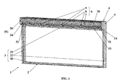
figure 1 est une vue schématisée et en perspective d'une installation de fermeture conforme à l'invention ; - la
figure 2 est une vue schématisée correspondant à un détail de l'installation de fermeture illustréefigure 1 ; - la
figure 3 est une vue schématisée, de côté et en coupe transversale de l'installation de fermeture illustréefigures 1 et2 .
- the
figure 1 is a schematic perspective view of a closure installation according to the invention; - the
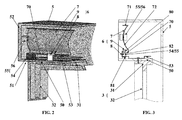
figure 2 is a schematic view corresponding to a detail of the illustrated closure installationfigure 1 ; - the
figure 3 is a schematic side view and in cross-section of the illustrated closure systemfigures 1 and2 .
La présente invention concerne le domaine du bâtiment et, plus particulièrement, celui de la fabrication des installations de fermeture d'une ouverture que comporte la maçonnerie d'un bâtiment.The present invention relates to the field of the building and, more particularly, that of the manufacture of closure systems of an opening that includes the masonry of a building.
Une telle installation de fermeture 1 comporte un système de fermeture 2 adoptant la forme d'une porte, d'une fenêtre ou analogue.Such a
Un tel système de fermeture 2 comporte, alors, une menuiserie 3 constituée par une traverse inférieure 30, une traverse supérieure 31 et des montants latéraux 32 raccordant la traverse inférieure 30 à la traverse supérieure 31. Cette traverse inférieure 30 et ces montants latéraux 32 sont rendus solidaires de la maçonnerie du bâtiment.Such a
Ce système de fermeture 2 comporte, encore, au moins un ouvrant (non représenté) monté de manière mobile (en pivotement ou en coulissement) sur la menuiserie 3, ceci entre une position d'ouverture et une position de fermeture du système de fermeture 2.This
Ladite installation de fermeture 1 comporte, encore, un système d'occultation 4 équipant un tel système de fermeture 2. Un tel système d'occultation 4 adopte la forme d'un volet roulant comportant des coulisses latérales (non représentées) usuellement rendues solidaires des montants latéraux 32 de la menuiserie 3 du système de fermeture 2.Said
Ce système d'occultation 4 comporte, encore, un tablier (non représenté) présentant des extrémités latérales aptes à coulisser à l'intérieur des coulisses latérales décrites ci-dessus, ceci entre une position déployée à l'avant du système de fermeture 2 et une position repliée au-dessus de ce système de fermeture 2.This occultation system 4 further comprises an apron (not shown) having lateral ends able to slide inside the lateral slides described above, this between a deployed position at the front of the
Ce système d'occultation 4 comporte, également, un caisson 5 à l'intérieur duquel est replié et à partir duquel est déployé le tablier mentionné ci-dessus. Ce caisson 5 comporte, alors, intérieurement, un arbre pour l'enroulement dudit tablier en position repliée à l'intérieur du caisson 5 et pour le déroulement de ce tablier en position déployée à l'avant du système de fermeture 2.This occultation system 4 also comprises a
Ce caisson 5 est monté sur la menuiserie 3, plus particulièrement en étant rapporté sur la menuiserie 3, ceci au-dessus de la traverse supérieure 31 de cette menuiserie 3 sur laquelle 31 est alors monté le caisson 5. De plus, ce caisson 5 est fixé sur cette menuiserie 3, plus particulièrement sur ladite traverse supérieure 31.This
A ce propos, on observera que ce caisson 5 comporte, alors usuellement, une sous-face 50 et que c'est, plus particulièrement, cette sous-face 50 qui est montée sur la menuiserie 3 (plus particulièrement en étant rapportée au-dessus de la traverse supérieure 31 de cette menuiserie 3) et qui est fixée sur cette menuiserie 3 (plus particulièrement sur ladite traverse supérieure 31).In this regard, it will be observed that this
Ce caisson 5 comporte, aussi et latéralement, des parties 51 de caisson 5, chacune surmontant un montant latéral 32 de la menuiserie 3 du système de fermeture 2 (voire rapportée et/ou prenant appui sur un tel montant latéral 32), un tel montant latéral 32 supportant alors une telle partie 51 de caisson 5. De plus, une telle partie 51 de caisson 5 est rendue solidaire (plus particulièrement par fixation) de la menuiserie 3 (plus particulièrement d'un montant latéral 32 de cette menuiserie 3) ce qui permet, avantageusement, d'immobiliser une telle partie 51 de caisson 5 par rapport à la menuiserie 3. On observera, également, que cette partie 51 de caisson 5 est, également, rendue solidaire de la maçonnerie, selon de cas, de manière directe et/ou indirecte (notamment en étant rendue solidaire de la menuiserie 3 comme décrit ci-dessus, cette menuiserie 3 étant, elle-même, rendue solidaire de la maçonnerie). Une telle solidarisation permet, avantageusement, d'immobiliser une telle partie 51 de caisson 5 par rapport à la maçonnerie.This
En fait, on observera qu'une telle partie 51 de caisson 5 peut, au moins en partie, être constituée par une console 52, refermant latéralement ledit caisson 5, et sur laquelle est montée en rotation ledit arbre d'enroulement/déroulement du tablier.In fact, it will be observed that such a
Finalement, ce caisson 5 peut comporter un renfort horizontal 53 qui est conçu pour renforcer l'installation de fermeture 1 (plus particulièrement le système de fermeture 2) vis-à-vis de contraintes horizontales (par exemple dues au vent, à une tentative d'effraction...) exercées sur ce système de fermeture 2.Finally, this
Un tel renfort horizontal 53 peut équiper tout type d'installation de fermeture 1 mais est, plus particulièrement, adapté pour équiper une installation de fermeture 1 comportant un système de fermeture 2 de grande longueur.Such a
En fait, un tel renfort horizontal 53 adopte, usuellement, la forme d'un profilé ou d'une plaque et/ou est réalisé en acier. Ce renfort horizontal 53 s'étend sur une partie au moins (voire et de préférence sur l'intégralité) de la longueur du caisson 5. Ce renfort horizontal 53 est rendu solidaire de la traverse supérieure 31 de la menuiserie 3, plus particulièrement par vissage. Tel que visible
A ce propos, on observera que cette traverse supérieure 31 peut présenter une flèche verticale, ceci sous l'effet de son propre poids et/ou de contraintes verticales exercées sur cette traverse supérieure 31. En fait, lorsque l'installation de fermeture 1 (plus particulièrement le caisson 5) comporte un renfort horizontal 53 tel que décrit ci-dessus, une telle contrainte verticale peut, alors, résulter du poids exercé par ce renfort horizontal 53, voire du fléchissement de ce renfort horizontal 53 sous son propre poids.In this respect, it will be observed that this
L'invention concerne, alors, un dispositif 6 de correction de la flèche verticale d'une telle traverse supérieure 31 de la menuiserie 3 d'un système de fermeture 2 associé à la maçonnerie d'un bâtiment.The invention relates, then, a
Ce dispositif 6 comporte :
- un renfort vertical 7, s'étendant de manière horizontale, destiné à s'étendre de manière sensiblement parallèle à la
traverse supérieure 31 de la menuiserie 3 et à être immobilisé (au moins verticalement) par rapport à la menuiserie 3, plus particulièrement par rapport à au moins un montant latéral 32 (de préférence par rapport aux deux montants latéraux 32) de cette menuiserie 3 ; - au moins une embase 8 destinée à coopérer avec la
traverse supérieure 31 de la menuiserie 3; - au moins un moyen de réglage 9 de la position verticale d'une telle embase 8 par rapport au renfort vertical 7.
- a
vertical reinforcement 7, extending horizontally, intended to extend substantially parallel to theupper rail 31 of thejoinery 3 and to be immobilized (at least vertically) with respect to thejoinery 3, more particularly in relation to at least one lateral upright 32 (preferably with respect to the two lateral uprights 32) of thisjoinery 3; - at least one base 8 intended to cooperate with the
upper rail 31 of thejoinery 3; - at least one adjusting means 9 for the vertical position of such a base 8 with respect to the
vertical reinforcement 7.
Un tel renfort vertical 7 comporte une console horizontale 70 avec laquelle coopèrent le ou les moyens de réglage 9 et destinée à prendre appui sur au moins un support 54 immobile par rapport à la menuiserie 3, plus particulièrement par rapport à au moins un montant latéral 32 de cette menuiserie 3.Such a
En fait, un tel renfort vertical 7 adopte au moins en partie la forme d'une cornière, d'une pièce en « U », d'un tube, d'une portion de tube, d'une pièce en arc de cercle (le rayon d'un tel arc de cercle peut, alors, correspondre sensiblement à celui du tablier du volet roulant en position repliée dans le caisson 5) ou autre.In fact, such a
Un tel renfort vertical 7 peut, alors, comporter une partie horizontale (plus particulièrement constituée par la console horizontale 70) et une partie verticale, se situant dans le prolongement de la partie horizontale.Such
Dans un pareil cas, ce renfort vertical 7 présente, avantageusement, une rigidité aussi bien dans le sens horizontal que dans le sens vertical.In such a case, this
De plus, la présence de cette partie verticale permet, avantageusement, de reprendre les contraintes exercées sur la partie horizontale (plus particulièrement constituée par la console horizontale 70) qui présente, alors, une faible inertie verticale.In addition, the presence of this vertical portion advantageously makes it possible to take up the stresses exerted on the horizontal part (more particularly constituted by the horizontal bracket 70) which then has a small vertical inertia.
En fait, la partie horizontale présente une forme plane et est, plus particulièrement, constituée par ladite console horizontale 70. La partie verticale présente une forme plane ou (et de préférence) un profil en arc de cercle. Un tel arc de cercle présente, de préférence, un rayon correspondant sensiblement à celui du tablier du volet roulant en position repliée dans le caisson 5In fact, the horizontal portion has a flat shape and is more particularly constituted by said
Un tel renfort vertical 7 peut, alors, adopter la forme d'une cornière comportant, d'une part, une partie horizontale constituée par une aile plane constituant la console horizontale 70 et, d'autre part, une partie verticale, selon le cas, présentant une forme plane ou (et de préférence) un profil en arc de cercle, plus particulièrement présentant les caractéristiques mentionnées ci-dessus.Such a
Tel que visible sur les figures en annexe, un tel renfort vertical 7 peut adopter la forme d'une pièce en « U » comportant deux ailes parallèles (70, 71) dont l'une 70 constitue la partie horizontale du renfort vertical 7 et/ou la console horizontale 70 mentionnées ci-dessus. Cette pièce en « U » comporte, encore, un fond 72, raccordant les deux ailes parallèles (70, 71), constituant la partie verticale du renfort vertical 7 et/ou présentant un profil en arc de cercle, plus particulièrement présentant les caractéristiques mentionnées ci-dessus.As can be seen in the appended figures, such a
En ce qui concerne ladite embase 8, celle-ci comporte au moins une aile horizontale (80, 81) avec laquelle coopèrent le ou les moyens de réglage 9 et/ou destinée à coopérer avec la traverse supérieure 31 de la menuiserie 3.With regard to said base 8, it comprises at least one horizontal flange (80, 81) with which cooperate or the adjusting means 9 and / or intended to cooperate with the
Ainsi, ladite embase 8 peut comporter une aile horizontale 80 avec laquelle coopèrent le ou les moyens de réglage 9.Thus, said base 8 may comprise a
Tel que visible sur les figures en annexe, cette aile horizontale 80 s'étend parallèlement à la console horizontale 70 du renfort vertical 7, plus particulièrement au-dessus de cette console horizontale 70.As can be seen in the appended figures, this
Ladite embase 8 peut, également, comporter une aile horizontale 81 destinée à coopérer avec la traverse supérieure 31.Said base 8 may also include a
Selon un premier mode de réalisation (non représenté), une telle aile horizontale 81 est destinée à coopérer directement avec ladite traverse supérieure 31 de la menuiserie 3, ceci en étant rendue solidaire de cette traverse supérieure 31 (directement ou au travers de la sous-face 50 du caisson 5), notamment par vissage.According to a first embodiment (not shown), such a
Cependant, il a été illustré sur les figures en annexe, une installation de fermeture 1 comportant un système d'occultation 4 incorporant un caisson 5 comportant un renfort horizontal 53 tel que décrit ci-dessus et rendu solidaire de la traverse supérieure 31 de la menuiserie 3.However, it has been illustrated in the figures in the appendix, a
Dans un pareil cas, l'aile horizontale 81 que comporte ladite embase 8 est destinée à coopérer avec ladite traverse supérieure 31, ceci de manière indirecte et par l'intermédiaire dudit renfort horizontal 53, plus particulièrement en venant s'accrocher sous un rebord d'accrochage que comporte ce renfort horizontal 53.In such a case, the
En fait et tel que visible sur les figures en annexe, ladite embase 8 peut être constituée par un cavalier en « U » ou par un profilé en « U » comportant deux ailes parallèles (80, 81), raccordées par un fond 82, et dont l'une 80 coopère avec le ou les moyens de réglage 9 et dont l'autre 81 est destinée à coopérer (directement ou indirectement) avec ladite traverse supérieure 31.In fact and as visible in the appended figures, said base 8 may be constituted by a "U" -shaped jumper or by a "U" -shaped profile comprising two parallel wings (80, 81), connected by a bottom 82, and one of which 80 cooperates with the or the adjustment means 9 and the other 81 is intended to cooperate (directly or indirectly) with said
On observera que lesdites ailes (80, 81) et, le cas échéant, le profilé en « U » s'étendent de manière horizontale et parallèle au renfort vertical 7, plus particulièrement parallèle à la console horizontale 70 de ce renfort vertical 7.It will be observed that said wings (80, 81) and, where appropriate, the "U" profile extend horizontally and parallel to the
Tel que mentionné ci-dessus, le dispositif 6 de correction comporte, également, au moins un moyen de réglage 9. Ce ou ces moyens de réglage 9 peuvent être constitués, chacun, par une vis, notamment de traction ou de compression, qui coopère avec l'embase 8 ainsi qu'avec le renfort vertical 7.As mentioned above, the
En fait et tel que visible sur les figures en annexe, un tel moyen de réglage 9 est interposé entre l'embase 8 et le renfort vertical 7, plus particulièrement entre l'aile horizontale 80 de l'embase 8 et la console horizontale 70 du renfort vertical 7.In fact and as visible in the appended figures, such adjustment means 9 is interposed between the base 8 and the
Aussi et selon un mode de réalisation préféré de l'invention illustré sur les figures en annexe, l'aile horizontale 80 de l'embase 8 s'étend parallèlement et au-dessus de la console horizontale 70 du renfort vertical 7 et est traversée par la ou les vis du ou des moyens de réglage 9, une telle vis prenant appui sur la console horizontale 70 de ce renfort vertical 7.Also and according to a preferred embodiment of the invention illustrated in the appended figures, the
La présente invention concerne, également, un caisson 5 de volet roulant que comporte le système d'occultation 4 d'une installation de fermeture 1.The present invention also relates to a
Ce caisson 5 présente les caractéristiques décrites ci-dessus. En particulier et tel que mentionné ci-dessus, ce caisson 5 est destiné à être monté et fixé sur la traverse supérieure 31 de la menuiserie 3 d'un système de fermeture 2 constitué par une porte, une fenêtre ou analogue.This
Selon l'invention, ce caisson 5 comporte un dispositif 6 de correction de la flèche verticale de la traverse supérieure 31 de la menuiserie 3, ce dispositif 6 présentant, alors, les caractéristiques décrites ci-dessus.According to the invention, this
Tel que mentionné ci-dessus, ce caisson 5 comporte, latéralement, des parties 51 de caisson 5 qui sont, chacune, au moins en partie, constituées par une console latérale 52.As mentioned above, this
De plus, chacune de ces parties 51 de caisson 5 est destinée à être supportée par un montant latéral 32 de la menuiserie 3 et chacune de ces parties 51 de caisson 5 comporte des moyens 55 pour recevoir le renfort vertical 7.In addition, each of these
En fait, ces moyens 55 pour recevoir le renfort vertical 7 comportent un support 54 sur lequel prend appui le renfort vertical 7 (plus particulièrement la console horizontale 70 de ce renfort vertical 7) et/ou un moyen 56 pour immobiliser ce renfort vertical 7 par rapport au caisson 5.In fact, these means 55 for receiving the
Ainsi, les moyens 55 pour recevoir le renfort vertical 7 comportent un support 54 sur lequel prend appui le renfort vertical 7. En fait et tel que visible sur les
A ce propos, on observera que, étant donné que c'est un montant latéral 32 de la menuiserie 3 qui supporte la partie 51 de caisson 5 comportant un tel support 54, un tel support 54 est, alors avantageusement, supporté par un tel montant latéral 32 de la menuiserie 3. Le renfort vertical 7, prenant appui sur un tel support 54 et supporté par un tel support 54, est alors avantageusement supporté par un tel montant latéral 32 de la menuiserie 3.In this regard, it will be observed that, since it is a
On observera, également, que la prise d'appui du renfort vertical 7 sur le support 54 permet, avantageusement, d'immobiliser verticalement ce renfort vertical 7 par rapport à la partie 51 de caisson 5 qui comporte ce support 54 et, donc, par rapport au caisson 5 lui-même.It will also be observed that the support of the
En prenant appui sur un tel support 54, le renfort vertical 7 ne pèse pas sur la traverse supérieure 31 de la menuiserie 3 et son poids ne vient pas s'ajouter au poids du renfort horizontal 53. Un tel renfort vertical 7 est, en quelque sorte, autoportant par rapport à cette traverse supérieure 31.By bearing on such a
Tel que mentionné ci-dessus, une telle partie 51 de caisson 5 est rendue solidaire de la menuiserie 3 (plus particulièrement d'un montant latéral 32 de cette menuiserie 3) ce qui permet, avantageusement, d'immobiliser, par rapport à la menuiserie 3 (plus particulièrement par rapport à un montant latéral 32 de cette menuiserie 3), une telle partie 51 de caisson 5 mais également un tel support 54 qui est, alors, également immobile par rapport à la menuiserie 3 (plus particulièrement par rapport à un montant latéral 32 de cette menuiserie 3). Il en résulte que, en prenant appui sur un tel support 54, le renfort vertical 7 est, alors, également immobile verticalement par rapport à la menuiserie 3 (plus particulièrement par rapport à un montant latéral 32 de cette menuiserie 3)As mentioned above, such a
Tel que mentionné ci-dessus, les moyens 55 pour recevoir le renfort vertical 7 comportent un moyen 56 pour immobiliser ce renfort vertical 7 par rapport au caisson 5.As mentioned above, the means 55 for receiving the
A ce propos, on observera que ce moyen pour immobiliser 56 est, plus particulièrement, conçu pour immobiliser horizontalement ce renfort vertical 7 par rapport au caisson 5, mais alors également par rapport à la menuiserie 3 ainsi que par rapport à la maçonnerie.In this respect, it will be observed that this means for immobilizing 56 is, more particularly, designed to immobilize horizontally this
En fait, un tel moyen pour immobiliser 56 est constitué par une pince, s'étendant intérieurement au caisson 5, équipant une console 52 de ce caisson 5, et coopérant avec le renfort vertical 7, plus particulièrement avec un côté latéral de ce renfort vertical 7.In fact, such a means for immobilizing 56 is constituted by a clamp, extending internally to the
Le caisson 5 peut, également, comporter un tablier (non représenté) ainsi qu'une paroi arrière (non représentée), refermant ce caisson 5, orientée en direction de l'intérieur du bâtiment recevant ce caisson 5. Le renfort vertical 7 est, alors, avantageusement, interposé entre ce tablier et cette paroi arrière.The
Tel que mentionné ci-dessus, le caisson 5 (plus particulièrement sa sous-face 50) est destiné à être rendu solidaire de la traverse supérieure 31 de la menuiserie 3.As mentioned above, the box 5 (more particularly its underside 50) is intended to be secured to the
C'est, également, avec cette traverse supérieure 31 de menuiserie 3 que sont destinées à coopérer (directement ou indirectement) la ou les embases 8 du dispositif 6 de correction de la flèche de cette traverse supérieure 31.It is also with this
En fait, une telle embase 8 peut coopérer directement avec cette traverse supérieure 31, ceci en étant rendue solidaire de celle-ci, notamment par vissage (solution non représentée).In fact, such a base 8 can cooperate directly with this
Cependant, une telle embase 8 peut, encore, coopérer avec cette traverse supérieure 31 de manière indirecte. Tel est, plus particulièrement, le cas lorsque le caisson 5 comporte un renfort horizontal 53 destiné à être rendu solidaire de cette traverse supérieure 31, notamment par vissage.However, such a base 8 may, again, cooperate with this
Dans un pareil cas, la ou les embases 8 coopèrent avec ce renfort horizontal 53, plus particulièrement par accrochage d'une aile 81 de cette embase 8 sous un rebord d'accrochage que comporte ce renfort horizontal 53.In such a case, or the bases 8 cooperate with this
Encore une autre caractéristique de l'invention consiste en ce que le dispositif de correction 6 est, avantageusement, positionné à l'intérieur dudit caisson 5. Un tel positionnement est particulièrement avantageux par rapport à un dispositif de correction, interposé entre le caisson et la menuiserie, et qui aurait pour conséquence de réduire la hauteur de la menuiserie et, par conséquent, de réduire la surface vitrée.Yet another characteristic of the invention consists in that the
Tel que mentionné ci-dessus, ce caisson 5 comporte une paroi arrière qui peut être de type amovible, notamment au moins en partie constituée par une trappe de visite.As mentioned above, this
La présence d'une telle paroi arrière permet, avantageusement, d'accéder à l'intérieur du caisson 5 et, donc, au dispositif de correction 6, plus particulièrement au moyen de réglage 9 de la position verticale de l'embase 8 par rapport au renfort vertical 7, ceci pour corriger la flèche verticale de la traverse supérieure 31.The presence of such a rear wall advantageously allows access to the interior of the
Finalement, l'invention concerne une installation de fermeture 1 d'une ouverture que présente la maçonnerie d'un bâtiment. Une telle installation de fermeture 1 présente les caractéristiques mentionnées ci-dessus.Finally, the invention relates to a
En particulier, une telle installation 1 comporte, d'une part, un système de fermeture 2 sous forme d'une porte, fenêtre ou analogue et incorporant une menuiserie 3 avec au moins des montants latéraux 32 et une traverse supérieure 31 et, d'autre part, un système d'occultation 4 incorporant un caisson 5 de volet roulant monté et fixé sur la traverse supérieure 31 de la menuiserie 3 du système de fermeture 2.In particular, such an
Selon l'invention, le caisson 5 de volet roulant de cette installation de fermeture 1 présente les caractéristiques décrites ci-dessus.According to the invention, the
En particulier, cette installation de fermeture 1 comporte un caisson 5 qui comporte, latéralement, des parties 51 de caisson 5 (plus particulièrement des consoles latérales 52) chacune supportée par un montant latéral 32 de la menuiserie 3, et chacune comportant des moyens 55 pour recevoir le renfort vertical 7.In particular, this
Dans cette installation 1, une telle partie 51 de caisson 5 comporte, alors et tel qu'il ressort de ce qui précède, un support 54, supporté par un montant latéral 32 de la menuiserie 3, et immobile (plus particulièrement verticalement) par rapport à cette menuiserie 3 (plus particulièrement par rapport à un montant latéral 32 de cette menuiserie 3).In this
Cette installation de fermeture 1 comporte, alors, aussi, un dispositif 6 de correction de la flèche de la traverse supérieure 31 de la menuiserie 3 de son système de fermeture 2. En particulier, cette installation 1 comporte un tel dispositif 6 comportant un renfort vertical 7, venant en appui sur le support 54, supporté par au moins un montant latéral 32 de la menuiserie 3, et immobile (plus particulièrement verticalement) par rapport à cette menuiserie 3 (plus particulièrement par rapport à au moins un montant latéral 32 de cette menuiserie 3).This
Claims (15)
Priority Applications (1)
| Application Number | Priority Date | Filing Date | Title |
|---|---|---|---|
| PL14172300T PL2816189T3 (en) | 2013-06-20 | 2014-06-13 | Device for correcting the vertical sag of an upper crossmember of the joinery of a closure system |
Applications Claiming Priority (1)
| Application Number | Priority Date | Filing Date | Title |
|---|---|---|---|
| FR1355811A FR3007447B1 (en) | 2013-06-20 | 2013-06-20 | DEVICE FOR CORRECTING THE VERTICAL ARROW OF A UPPER CROSS OF THE JOINERY OF A CLOSURE SYSTEM |
Publications (3)
| Publication Number | Publication Date |
|---|---|
| EP2816189A2 true EP2816189A2 (en) | 2014-12-24 |
| EP2816189A3 EP2816189A3 (en) | 2015-01-07 |
| EP2816189B1 EP2816189B1 (en) | 2017-08-02 |
Family
ID=49237347
Family Applications (1)
| Application Number | Title | Priority Date | Filing Date |
|---|---|---|---|
| EP14172300.7A Active EP2816189B1 (en) | 2013-06-20 | 2014-06-13 | Device for correcting the vertical sag of an upper crossmember of the joinery of a closure system |
Country Status (4)
| Country | Link |
|---|---|
| EP (1) | EP2816189B1 (en) |
| ES (1) | ES2641556T3 (en) |
| FR (1) | FR3007447B1 (en) |
| PL (1) | PL2816189T3 (en) |
Cited By (2)
| Publication number | Priority date | Publication date | Assignee | Title |
|---|---|---|---|---|
| CN110273551A (en) * | 2019-07-17 | 2019-09-24 | 中国能源建设集团山西电力建设有限公司 | Amount of deflection means for correcting and bearing calibration when upper and lower stoplog connection |
| FR3113297A1 (en) * | 2020-08-07 | 2022-02-11 | Societe De Production De Portes Et Fermetures | Roller shutter box equipped with an interior longitudinal reinforcement structure |
Families Citing this family (1)
| Publication number | Priority date | Publication date | Assignee | Title |
|---|---|---|---|---|
| FR3142775A1 (en) * | 2022-12-02 | 2024-06-07 | Societe De Production De Portes Et Fermetures | Roller shutter box |
Family Cites Families (3)
| Publication number | Priority date | Publication date | Assignee | Title |
|---|---|---|---|---|
| DE9404779U1 (en) * | 1994-03-23 | 1994-06-30 | PaX GmbH, 55218 Ingelheim | Window or door frames, especially for roller shutter box installation above |
| FR2952961A1 (en) * | 2009-11-26 | 2011-05-27 | Bubendorff | DEVICE FOR CLOSING A MASONRY OPENING OF A BUILDING |
| FR2974592B1 (en) * | 2011-04-28 | 2013-06-07 | Fixolite Sa | BAY EQUIPMENT AND REINFORCED SHUTTER BOX AS PART OF THIS EQUIPMENT |
-
2013
- 2013-06-20 FR FR1355811A patent/FR3007447B1/en not_active Expired - Fee Related
-
2014
- 2014-06-13 PL PL14172300T patent/PL2816189T3/en unknown
- 2014-06-13 EP EP14172300.7A patent/EP2816189B1/en active Active
- 2014-06-13 ES ES14172300.7T patent/ES2641556T3/en active Active
Non-Patent Citations (1)
| Title |
|---|
| None |
Cited By (3)
| Publication number | Priority date | Publication date | Assignee | Title |
|---|---|---|---|---|
| CN110273551A (en) * | 2019-07-17 | 2019-09-24 | 中国能源建设集团山西电力建设有限公司 | Amount of deflection means for correcting and bearing calibration when upper and lower stoplog connection |
| CN110273551B (en) * | 2019-07-17 | 2024-02-09 | 中国能源建设集团山西电力建设有限公司 | Deflection correction device and correction method for upper and lower stopbeams during connection |
| FR3113297A1 (en) * | 2020-08-07 | 2022-02-11 | Societe De Production De Portes Et Fermetures | Roller shutter box equipped with an interior longitudinal reinforcement structure |
Also Published As
| Publication number | Publication date |
|---|---|
| PL2816189T3 (en) | 2018-01-31 |
| ES2641556T3 (en) | 2017-11-10 |
| FR3007447A1 (en) | 2014-12-26 |
| EP2816189A3 (en) | 2015-01-07 |
| EP2816189B1 (en) | 2017-08-02 |
| FR3007447B1 (en) | 2017-12-01 |
Similar Documents
| Publication | Publication Date | Title |
|---|---|---|
| EP2816189B1 (en) | Device for correcting the vertical sag of an upper crossmember of the joinery of a closure system | |
| FR2961245A1 (en) | Device for guiding sliding motion of e.g. retractable sliding shower door in dwelling during opening of door, has lower guide rail arranged inside upper guide rail and fixed with upper guide rail in removable manner by locking unit | |
| EP2952670B1 (en) | Method for manufacturing and installing a gate | |
| EP0952296B1 (en) | Roller shutter box | |
| EP0651110B1 (en) | Immobilization device of a vertical stiffener of railings opposing a floor support | |
| EP2873783B1 (en) | Device for closing a roof opening | |
| FR2974592A1 (en) | Bay equipment for building, has reinforcement unit comprising metal profile that is secured to end of inner wing of boot and is assembled rigidly, directly or indirectly with top rail of carpentry or window or door | |
| EP2333226B1 (en) | Roller shutter box with exterior reinforcing profile | |
| FR2743596A1 (en) | WINDOW SHUTTER, DOOR, U-SHAPED STRUCTURE | |
| WO2024132748A1 (en) | Building facade panel and method for installing same | |
| EP0728903B1 (en) | Roller blind for a door, window or the like | |
| FR2951475A1 (en) | DEVICE FOR COVERING A MASS OF WALL | |
| FR3024487A1 (en) | CARPENTRY STRUCTURE COMPRISING A DORMANT AND A SHUTTER BOX | |
| FR3127514A1 (en) | Device for supporting a roller shutter winding tube in a roller shutter box, assembly sub-assembly and protective installation comprising such a support device and associated method of assembly | |
| EP0845569A1 (en) | Running wheel assembly for sliding door | |
| FR3042530A1 (en) | MULTIVITRATING HEDGE | |
| FR2893348A1 (en) | Mounting system for roller blinds comprises two brackets with hooks which fit over tops of lateral guide rails for edges of blind, positioning lugs at bases of brackets fitting into bores in rail walls | |
| FR3118642A1 (en) | GUIDE RAIL FOR AN AWNING | |
| FR3032219A1 (en) | A WIND STOP DEVICE MOUNTED ON FOLDING PANELS | |
| EP1916378A2 (en) | Support device for a roller blind for an opening block assembly, and opening block assembly equipped with such a device | |
| EP1939383B1 (en) | System for closing a storage area with sliding door(s) | |
| FR3051822A1 (en) | ASSEMBLY FOR FITTING A MOSQUITO NET ON THE SLIDERS OF A SHUTTER | |
| EP1785566A1 (en) | Suspension and slide support for vertical panels | |
| FR3091718A1 (en) | Roller shutter structure comprising a box provided with a longitudinal support extension | |
| FR2932522A1 (en) | Frame for door of sectional garage, has lintel and carrier profiles simultaneously oriented so that bubble levels indicate horizontal direction to fix lintel and profiles horizontally |
Legal Events
| Date | Code | Title | Description |
|---|---|---|---|
| PUAL | Search report despatched |
Free format text: ORIGINAL CODE: 0009013 |
|
| PUAI | Public reference made under article 153(3) epc to a published international application that has entered the european phase |
Free format text: ORIGINAL CODE: 0009012 |
|
| 17P | Request for examination filed |
Effective date: 20140613 |
|
| AK | Designated contracting states |
Kind code of ref document: A2 Designated state(s): AL AT BE BG CH CY CZ DE DK EE ES FI FR GB GR HR HU IE IS IT LI LT LU LV MC MK MT NL NO PL PT RO RS SE SI SK SM TR |
|
| AX | Request for extension of the european patent |
Extension state: BA ME |
|
| AK | Designated contracting states |
Kind code of ref document: A3 Designated state(s): AL AT BE BG CH CY CZ DE DK EE ES FI FR GB GR HR HU IE IS IT LI LT LU LV MC MK MT NL NO PL PT RO RS SE SI SK SM TR |
|
| AX | Request for extension of the european patent |
Extension state: BA ME |
|
| RIC1 | Information provided on ipc code assigned before grant |
Ipc: E06B 9/17 20060101AFI20141128BHEP |
|
| R17P | Request for examination filed (corrected) |
Effective date: 20150626 |
|
| RBV | Designated contracting states (corrected) |
Designated state(s): AL AT BE BG CH CY CZ DE DK EE ES FI FR GB GR HR HU IE IS IT LI LT LU LV MC MK MT NL NO PL PT RO RS SE SI SK SM TR |
|
| 17Q | First examination report despatched |
Effective date: 20160725 |
|
| GRAP | Despatch of communication of intention to grant a patent |
Free format text: ORIGINAL CODE: EPIDOSNIGR1 |
|
| INTG | Intention to grant announced |
Effective date: 20170306 |
|
| GRAS | Grant fee paid |
Free format text: ORIGINAL CODE: EPIDOSNIGR3 |
|
| GRAA | (expected) grant |
Free format text: ORIGINAL CODE: 0009210 |
|
| AK | Designated contracting states |
Kind code of ref document: B1 Designated state(s): AL AT BE BG CH CY CZ DE DK EE ES FI FR GB GR HR HU IE IS IT LI LT LU LV MC MK MT NL NO PL PT RO RS SE SI SK SM TR |
|
| REG | Reference to a national code |
Ref country code: CH Ref legal event code: EP Ref country code: AT Ref legal event code: REF Ref document number: 914677 Country of ref document: AT Kind code of ref document: T Effective date: 20170815 |
|
| REG | Reference to a national code |
Ref country code: IE Ref legal event code: FG4D Free format text: LANGUAGE OF EP DOCUMENT: FRENCH |
|
| REG | Reference to a national code |
Ref country code: DE Ref legal event code: R096 Ref document number: 602014012440 Country of ref document: DE |
|
| REG | Reference to a national code |
Ref country code: ES Ref legal event code: FG2A Ref document number: 2641556 Country of ref document: ES Kind code of ref document: T3 Effective date: 20171110 |
|
| REG | Reference to a national code |
Ref country code: NL Ref legal event code: MP Effective date: 20170802 |
|
| REG | Reference to a national code |
Ref country code: AT Ref legal event code: MK05 Ref document number: 914677 Country of ref document: AT Kind code of ref document: T Effective date: 20170802 |
|
| REG | Reference to a national code |
Ref country code: LT Ref legal event code: MG4D |
|
| PG25 | Lapsed in a contracting state [announced via postgrant information from national office to epo] |
Ref country code: FI Free format text: LAPSE BECAUSE OF FAILURE TO SUBMIT A TRANSLATION OF THE DESCRIPTION OR TO PAY THE FEE WITHIN THE PRESCRIBED TIME-LIMIT Effective date: 20170802 Ref country code: AT Free format text: LAPSE BECAUSE OF FAILURE TO SUBMIT A TRANSLATION OF THE DESCRIPTION OR TO PAY THE FEE WITHIN THE PRESCRIBED TIME-LIMIT Effective date: 20170802 Ref country code: LT Free format text: LAPSE BECAUSE OF FAILURE TO SUBMIT A TRANSLATION OF THE DESCRIPTION OR TO PAY THE FEE WITHIN THE PRESCRIBED TIME-LIMIT Effective date: 20170802 Ref country code: NL Free format text: LAPSE BECAUSE OF FAILURE TO SUBMIT A TRANSLATION OF THE DESCRIPTION OR TO PAY THE FEE WITHIN THE PRESCRIBED TIME-LIMIT Effective date: 20170802 Ref country code: SE Free format text: LAPSE BECAUSE OF FAILURE TO SUBMIT A TRANSLATION OF THE DESCRIPTION OR TO PAY THE FEE WITHIN THE PRESCRIBED TIME-LIMIT Effective date: 20170802 Ref country code: NO Free format text: LAPSE BECAUSE OF FAILURE TO SUBMIT A TRANSLATION OF THE DESCRIPTION OR TO PAY THE FEE WITHIN THE PRESCRIBED TIME-LIMIT Effective date: 20171102 Ref country code: HR Free format text: LAPSE BECAUSE OF FAILURE TO SUBMIT A TRANSLATION OF THE DESCRIPTION OR TO PAY THE FEE WITHIN THE PRESCRIBED TIME-LIMIT Effective date: 20170802 |
|
| PG25 | Lapsed in a contracting state [announced via postgrant information from national office to epo] |
Ref country code: LV Free format text: LAPSE BECAUSE OF FAILURE TO SUBMIT A TRANSLATION OF THE DESCRIPTION OR TO PAY THE FEE WITHIN THE PRESCRIBED TIME-LIMIT Effective date: 20170802 Ref country code: GR Free format text: LAPSE BECAUSE OF FAILURE TO SUBMIT A TRANSLATION OF THE DESCRIPTION OR TO PAY THE FEE WITHIN THE PRESCRIBED TIME-LIMIT Effective date: 20171103 Ref country code: RS Free format text: LAPSE BECAUSE OF FAILURE TO SUBMIT A TRANSLATION OF THE DESCRIPTION OR TO PAY THE FEE WITHIN THE PRESCRIBED TIME-LIMIT Effective date: 20170802 Ref country code: BG Free format text: LAPSE BECAUSE OF FAILURE TO SUBMIT A TRANSLATION OF THE DESCRIPTION OR TO PAY THE FEE WITHIN THE PRESCRIBED TIME-LIMIT Effective date: 20171102 Ref country code: IS Free format text: LAPSE BECAUSE OF FAILURE TO SUBMIT A TRANSLATION OF THE DESCRIPTION OR TO PAY THE FEE WITHIN THE PRESCRIBED TIME-LIMIT Effective date: 20171202 |
|
| PG25 | Lapsed in a contracting state [announced via postgrant information from national office to epo] |
Ref country code: DK Free format text: LAPSE BECAUSE OF FAILURE TO SUBMIT A TRANSLATION OF THE DESCRIPTION OR TO PAY THE FEE WITHIN THE PRESCRIBED TIME-LIMIT Effective date: 20170802 Ref country code: RO Free format text: LAPSE BECAUSE OF FAILURE TO SUBMIT A TRANSLATION OF THE DESCRIPTION OR TO PAY THE FEE WITHIN THE PRESCRIBED TIME-LIMIT Effective date: 20170802 Ref country code: CZ Free format text: LAPSE BECAUSE OF FAILURE TO SUBMIT A TRANSLATION OF THE DESCRIPTION OR TO PAY THE FEE WITHIN THE PRESCRIBED TIME-LIMIT Effective date: 20170802 |
|
| REG | Reference to a national code |
Ref country code: DE Ref legal event code: R097 Ref document number: 602014012440 Country of ref document: DE |
|
| PG25 | Lapsed in a contracting state [announced via postgrant information from national office to epo] |
Ref country code: SK Free format text: LAPSE BECAUSE OF FAILURE TO SUBMIT A TRANSLATION OF THE DESCRIPTION OR TO PAY THE FEE WITHIN THE PRESCRIBED TIME-LIMIT Effective date: 20170802 Ref country code: EE Free format text: LAPSE BECAUSE OF FAILURE TO SUBMIT A TRANSLATION OF THE DESCRIPTION OR TO PAY THE FEE WITHIN THE PRESCRIBED TIME-LIMIT Effective date: 20170802 Ref country code: SM Free format text: LAPSE BECAUSE OF FAILURE TO SUBMIT A TRANSLATION OF THE DESCRIPTION OR TO PAY THE FEE WITHIN THE PRESCRIBED TIME-LIMIT Effective date: 20170802 |
|
| PLBE | No opposition filed within time limit |
Free format text: ORIGINAL CODE: 0009261 |
|
| STAA | Information on the status of an ep patent application or granted ep patent |
Free format text: STATUS: NO OPPOSITION FILED WITHIN TIME LIMIT |
|
| REG | Reference to a national code |
Ref country code: FR Ref legal event code: PLFP Year of fee payment: 5 |
|
| 26N | No opposition filed |
Effective date: 20180503 |
|
| PG25 | Lapsed in a contracting state [announced via postgrant information from national office to epo] |
Ref country code: SI Free format text: LAPSE BECAUSE OF FAILURE TO SUBMIT A TRANSLATION OF THE DESCRIPTION OR TO PAY THE FEE WITHIN THE PRESCRIBED TIME-LIMIT Effective date: 20170802 |
|
| PG25 | Lapsed in a contracting state [announced via postgrant information from national office to epo] |
Ref country code: MT Free format text: LAPSE BECAUSE OF FAILURE TO SUBMIT A TRANSLATION OF THE DESCRIPTION OR TO PAY THE FEE WITHIN THE PRESCRIBED TIME-LIMIT Effective date: 20170802 |
|
| REG | Reference to a national code |
Ref country code: CH Ref legal event code: PL |
|
| GBPC | Gb: european patent ceased through non-payment of renewal fee |
Effective date: 20180613 |
|
| REG | Reference to a national code |
Ref country code: BE Ref legal event code: MM Effective date: 20180630 |
|
| REG | Reference to a national code |
Ref country code: IE Ref legal event code: MM4A |
|
| PG25 | Lapsed in a contracting state [announced via postgrant information from national office to epo] |
Ref country code: MC Free format text: LAPSE BECAUSE OF FAILURE TO SUBMIT A TRANSLATION OF THE DESCRIPTION OR TO PAY THE FEE WITHIN THE PRESCRIBED TIME-LIMIT Effective date: 20170802 Ref country code: LU Free format text: LAPSE BECAUSE OF NON-PAYMENT OF DUE FEES Effective date: 20180613 |
|
| PG25 | Lapsed in a contracting state [announced via postgrant information from national office to epo] |
Ref country code: LI Free format text: LAPSE BECAUSE OF NON-PAYMENT OF DUE FEES Effective date: 20180630 Ref country code: CH Free format text: LAPSE BECAUSE OF NON-PAYMENT OF DUE FEES Effective date: 20180630 Ref country code: IE Free format text: LAPSE BECAUSE OF NON-PAYMENT OF DUE FEES Effective date: 20180613 Ref country code: GB Free format text: LAPSE BECAUSE OF NON-PAYMENT OF DUE FEES Effective date: 20180613 |
|
| PG25 | Lapsed in a contracting state [announced via postgrant information from national office to epo] |
Ref country code: BE Free format text: LAPSE BECAUSE OF NON-PAYMENT OF DUE FEES Effective date: 20180630 |
|
| PG25 | Lapsed in a contracting state [announced via postgrant information from national office to epo] |
Ref country code: TR Free format text: LAPSE BECAUSE OF FAILURE TO SUBMIT A TRANSLATION OF THE DESCRIPTION OR TO PAY THE FEE WITHIN THE PRESCRIBED TIME-LIMIT Effective date: 20170802 |
|
| PG25 | Lapsed in a contracting state [announced via postgrant information from national office to epo] |
Ref country code: PT Free format text: LAPSE BECAUSE OF FAILURE TO SUBMIT A TRANSLATION OF THE DESCRIPTION OR TO PAY THE FEE WITHIN THE PRESCRIBED TIME-LIMIT Effective date: 20170802 Ref country code: HU Free format text: LAPSE BECAUSE OF FAILURE TO SUBMIT A TRANSLATION OF THE DESCRIPTION OR TO PAY THE FEE WITHIN THE PRESCRIBED TIME-LIMIT; INVALID AB INITIO Effective date: 20140613 |
|
| PG25 | Lapsed in a contracting state [announced via postgrant information from national office to epo] |
Ref country code: MK Free format text: LAPSE BECAUSE OF NON-PAYMENT OF DUE FEES Effective date: 20170802 Ref country code: CY Free format text: LAPSE BECAUSE OF FAILURE TO SUBMIT A TRANSLATION OF THE DESCRIPTION OR TO PAY THE FEE WITHIN THE PRESCRIBED TIME-LIMIT Effective date: 20170802 |
|
| PG25 | Lapsed in a contracting state [announced via postgrant information from national office to epo] |
Ref country code: AL Free format text: LAPSE BECAUSE OF FAILURE TO SUBMIT A TRANSLATION OF THE DESCRIPTION OR TO PAY THE FEE WITHIN THE PRESCRIBED TIME-LIMIT Effective date: 20170802 |
|
| PGFP | Annual fee paid to national office [announced via postgrant information from national office to epo] |
Ref country code: DE Payment date: 20230629 Year of fee payment: 10 |
|
| PGFP | Annual fee paid to national office [announced via postgrant information from national office to epo] |
Ref country code: ES Payment date: 20230807 Year of fee payment: 10 |
|
| PGFP | Annual fee paid to national office [announced via postgrant information from national office to epo] |
Ref country code: IT Payment date: 20240627 Year of fee payment: 11 Ref country code: FR Payment date: 20240624 Year of fee payment: 11 |
|
| PGFP | Annual fee paid to national office [announced via postgrant information from national office to epo] |
Ref country code: PL Payment date: 20240528 Year of fee payment: 11 |