EP2815637B1 - Druckausgleichselement mit einer membran, gehäuse, batteriezellenmodul sowie kraftfahrzeug - Google Patents
Druckausgleichselement mit einer membran, gehäuse, batteriezellenmodul sowie kraftfahrzeug Download PDFInfo
- Publication number
- EP2815637B1 EP2815637B1 EP13701414.8A EP13701414A EP2815637B1 EP 2815637 B1 EP2815637 B1 EP 2815637B1 EP 13701414 A EP13701414 A EP 13701414A EP 2815637 B1 EP2815637 B1 EP 2815637B1
- Authority
- EP
- European Patent Office
- Prior art keywords
- housing
- membrane
- battery cell
- cell module
- pressure equalization
- Prior art date
- Legal status (The legal status is an assumption and is not a legal conclusion. Google has not performed a legal analysis and makes no representation as to the accuracy of the status listed.)
- Active
Links
- 239000012528 membrane Substances 0.000 claims description 22
- 229910001416 lithium ion Inorganic materials 0.000 claims description 6
- HBBGRARXTFLTSG-UHFFFAOYSA-N Lithium ion Chemical compound [Li+] HBBGRARXTFLTSG-UHFFFAOYSA-N 0.000 claims description 5
- 230000001681 protective effect Effects 0.000 claims description 4
- 230000002209 hydrophobic effect Effects 0.000 claims description 3
- -1 polytetrafluoroethylene Polymers 0.000 claims description 3
- 229920001343 polytetrafluoroethylene Polymers 0.000 claims description 3
- 239000004810 polytetrafluoroethylene Substances 0.000 claims description 3
- 238000001035 drying Methods 0.000 claims 1
- 239000002274 desiccant Substances 0.000 description 13
- 239000003570 air Substances 0.000 description 5
- XLYOFNOQVPJJNP-UHFFFAOYSA-N water Chemical compound O XLYOFNOQVPJJNP-UHFFFAOYSA-N 0.000 description 4
- 150000003839 salts Chemical class 0.000 description 3
- VYPSYNLAJGMNEJ-UHFFFAOYSA-N Silicium dioxide Chemical compound O=[Si]=O VYPSYNLAJGMNEJ-UHFFFAOYSA-N 0.000 description 2
- 210000003323 beak Anatomy 0.000 description 2
- 238000009833 condensation Methods 0.000 description 2
- 230000005494 condensation Effects 0.000 description 2
- 239000007788 liquid Substances 0.000 description 2
- 239000000463 material Substances 0.000 description 2
- KRHYYFGTRYWZRS-UHFFFAOYSA-N Fluorane Chemical compound F KRHYYFGTRYWZRS-UHFFFAOYSA-N 0.000 description 1
- 229910013870 LiPF 6 Inorganic materials 0.000 description 1
- WHXSMMKQMYFTQS-UHFFFAOYSA-N Lithium Chemical compound [Li] WHXSMMKQMYFTQS-UHFFFAOYSA-N 0.000 description 1
- 239000012080 ambient air Substances 0.000 description 1
- 239000004927 clay Substances 0.000 description 1
- 239000000356 contaminant Substances 0.000 description 1
- 230000007797 corrosion Effects 0.000 description 1
- 238000005260 corrosion Methods 0.000 description 1
- 238000009831 deintercalation Methods 0.000 description 1
- 238000011161 development Methods 0.000 description 1
- 230000018109 developmental process Effects 0.000 description 1
- 238000009792 diffusion process Methods 0.000 description 1
- 230000007062 hydrolysis Effects 0.000 description 1
- 238000006460 hydrolysis reaction Methods 0.000 description 1
- 239000012535 impurity Substances 0.000 description 1
- 238000009830 intercalation Methods 0.000 description 1
- 230000002687 intercalation Effects 0.000 description 1
- 229910052744 lithium Inorganic materials 0.000 description 1
- 239000002808 molecular sieve Substances 0.000 description 1
- 230000000717 retained effect Effects 0.000 description 1
- 239000000377 silicon dioxide Substances 0.000 description 1
- URGAHOPLAPQHLN-UHFFFAOYSA-N sodium aluminosilicate Chemical compound [Na+].[Al+3].[O-][Si]([O-])=O.[O-][Si]([O-])=O URGAHOPLAPQHLN-UHFFFAOYSA-N 0.000 description 1
- 239000007787 solid Substances 0.000 description 1
- 239000004575 stone Substances 0.000 description 1
- 238000003466 welding Methods 0.000 description 1
Images

Classifications
-
- F—MECHANICAL ENGINEERING; LIGHTING; HEATING; WEAPONS; BLASTING
- F16—ENGINEERING ELEMENTS AND UNITS; GENERAL MEASURES FOR PRODUCING AND MAINTAINING EFFECTIVE FUNCTIONING OF MACHINES OR INSTALLATIONS; THERMAL INSULATION IN GENERAL
- F16K—VALVES; TAPS; COCKS; ACTUATING-FLOATS; DEVICES FOR VENTING OR AERATING
- F16K15/00—Check valves
- F16K15/02—Check valves with guided rigid valve members
- F16K15/04—Check valves with guided rigid valve members shaped as balls
- F16K15/044—Check valves with guided rigid valve members shaped as balls spring-loaded
-
- F—MECHANICAL ENGINEERING; LIGHTING; HEATING; WEAPONS; BLASTING
- F16—ENGINEERING ELEMENTS AND UNITS; GENERAL MEASURES FOR PRODUCING AND MAINTAINING EFFECTIVE FUNCTIONING OF MACHINES OR INSTALLATIONS; THERMAL INSULATION IN GENERAL
- F16K—VALVES; TAPS; COCKS; ACTUATING-FLOATS; DEVICES FOR VENTING OR AERATING
- F16K15/00—Check valves
- F16K15/14—Check valves with flexible valve members
- F16K15/144—Check valves with flexible valve members the closure elements being fixed along all or a part of their periphery
- F16K15/147—Check valves with flexible valve members the closure elements being fixed along all or a part of their periphery the closure elements having specially formed slits or being of an elongated easily collapsible form
-
- F—MECHANICAL ENGINEERING; LIGHTING; HEATING; WEAPONS; BLASTING
- F16—ENGINEERING ELEMENTS AND UNITS; GENERAL MEASURES FOR PRODUCING AND MAINTAINING EFFECTIVE FUNCTIONING OF MACHINES OR INSTALLATIONS; THERMAL INSULATION IN GENERAL
- F16K—VALVES; TAPS; COCKS; ACTUATING-FLOATS; DEVICES FOR VENTING OR AERATING
- F16K15/00—Check valves
- F16K15/14—Check valves with flexible valve members
- F16K15/148—Check valves with flexible valve members the closure elements being fixed in their centre
-
- F—MECHANICAL ENGINEERING; LIGHTING; HEATING; WEAPONS; BLASTING
- F16—ENGINEERING ELEMENTS AND UNITS; GENERAL MEASURES FOR PRODUCING AND MAINTAINING EFFECTIVE FUNCTIONING OF MACHINES OR INSTALLATIONS; THERMAL INSULATION IN GENERAL
- F16K—VALVES; TAPS; COCKS; ACTUATING-FLOATS; DEVICES FOR VENTING OR AERATING
- F16K17/00—Safety valves; Equalising valves, e.g. pressure relief valves
- F16K17/18—Safety valves; Equalising valves, e.g. pressure relief valves opening on surplus pressure on either side
- F16K17/19—Equalising valves predominantly for tanks
- F16K17/196—Equalising valves predominantly for tanks spring-loaded
-
- H—ELECTRICITY
- H05—ELECTRIC TECHNIQUES NOT OTHERWISE PROVIDED FOR
- H05K—PRINTED CIRCUITS; CASINGS OR CONSTRUCTIONAL DETAILS OF ELECTRIC APPARATUS; MANUFACTURE OF ASSEMBLAGES OF ELECTRICAL COMPONENTS
- H05K5/00—Casings, cabinets or drawers for electric apparatus
- H05K5/02—Details
- H05K5/0213—Venting apertures; Constructional details thereof
- H05K5/0216—Venting plugs comprising semi-permeable membranes
Definitions
- the present invention relates to a pressure compensation element for a housing, which has a membrane, a housing, a battery cell module and a motor vehicle.
- a battery cell is made up of electrochemical elements that are sensitive to external influences such as air or moisture and therefore need to be protected as much as possible.
- LiPF 6 Lithium-hexa-fluorophosphate
- This conductive salt is extremely reactive to moisture, so that hydrogen fluoride (HF) can be formed by hydrolysis.
- the pressure compensation element may be formed by a membrane. Since a certain amount of water vapor is always present in the ambient air, it passes through the membrane into the housing through volume exchange and diffusion.
- a desiccant In order to prevent said problems by condensation in the interior of the housing, a desiccant is usually used. Even with the smallest housing volume, however, over a lifetime of several years, a desiccant mass of a few kilograms is required or it is necessary to provide an exchange of the desiccant.
- a pressure compensation element for a housing for receiving an electronic circuit is known, which consists of a semipermeable membrane which is arranged protected in an electrical connector element.
- Another example of pressure compensation element for a housing is from the GB-A-2401330 known.
- a pressure compensation element for a housing, for example for accommodating lithium-ion accumulators, in which a membrane, preferably a hydrophobic and / or oleophobic membrane, is connected in series with at least two check valves arranged in parallel and opposite to one another.
- the check valves each have a defined opening pressure, so that advantageously the volume exchange of the housing interior with the environment and thus an entry of moisture and other contaminants can be reduced to a minimum.
- Suitable check valves are known to those skilled in the art.
- throttle check, umbrella, beak or spring loaded ball seat valves are used.
- the said valves can be combined as desired.
- valves can be varied depending on the compressive stress and the opening pressure with respect to the material and / or the springs of the valves.
- the membrane is only gas-permeable, so that solid impurities and liquids are retained.
- the membrane may be hydrophobic and / or oleophobic equipped so that over liquids, especially water, increased protection is given.
- Suitable materials for such membranes are known to the person skilled in the art, preference is given to membranes made of polytetrafluoroethylene (PTFE).
- PTFE polytetrafluoroethylene
- this is provided with a desiccant, which is preferably arranged in a desiccant container and the at least two check valves are arranged downstream.
- this can safely be ensured that any moisture is prevented from entering the housing, whereby corrosion and short circuits can be reliably prevented.
- the amount of desiccant may be such that it is sufficient over the life of, for example, a rechargeable battery located in the housing.
- the amount of desiccant can be located in a replaceable desiccant container, which must be replaced at defined intervals. It is particularly advantageous that the amount of desiccant needed can be kept even lower than in the other embodiments of the invention.
- Suitable desiccants are well known to those skilled in the art. Preference is given to silica, molecular sieve or clay-based drying agents.
- the membrane is preferably provided with a protective cap, so that mechanical damage to the membrane can be prevented.
- a housing which has a pressure compensation element according to the invention is claimed for moisture-sensitive components or devices in which condensation must not occur, such as control devices or battery modules.
- subject of this invention is also a battery cell module, preferably a lithium-ion battery with a housing according to the invention.
- the subject matter of the invention is a motor vehicle, in particular a motor vehicle driven by a motor vehicle, which has at least one battery cell module according to the invention which is connected to a drive system of the motor vehicle.
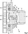
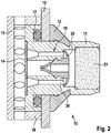
- FIG. 2 and FIG. 3 each show a pressure compensation element 10 according to the invention, which is arranged via a base holder 11 in a passage opening of a wall 12 of a housing, not shown.
- the base holder 11 is fixed on the inside of the housing by means of a snap closure 13 or a screw connection, not shown. Other types of attachment are possible.
- the base holder 11 On the outside of the housing, the base holder 11 carries a membrane 14 which is covered by a protective cap 15. Radially 15 holes are provided on the cap, can pass through the air and water. The air can pass through the membrane 14 further into the housing or out of the housing. The water is released through the holes back to the environment.
- the holes may also be in the form of slots.
- the protective cap 15 may have a snap closure 16, as in FIG.
- the base holder 11 is sealed against the wall 12 by means of a secondary seal 17.
- check valves 19 are arranged in the region of inlet and outflow areas of passage openings 20 in order to move the Control pressure equalization.
- check valves 19 are two umbrella valves 24 ( FIG. 1 ), a combination of umbrella and beak valve 25 ( FIG. 2 ) and spring-loaded ball seat valves 23 (FIG. FIG. 3 ) intended.
- the base holder 11 has on the inside of the housing to a container filled with desiccant 21, passes through the exchanged air into the interior of the housing and is dried.
- the container 21 may be clipped, crimped or screwed to the base holder 11.
Landscapes
- Engineering & Computer Science (AREA)
- General Engineering & Computer Science (AREA)
- Mechanical Engineering (AREA)
- Microelectronics & Electronic Packaging (AREA)
- Battery Mounting, Suspending (AREA)
Description
- Die vorliegende Erfindung betrifft ein Druckausgleichselement für ein Gehäuse, das eine Membran aufweist, ein Gehäuse, ein Batteriezellenmodul sowie ein Kraftfahrzeug.
- Es besteht ein erheblicher Bedarf an Batterien für breite Anwendungsbereiche, beispielsweise für Fahrzeuge, stationäre Anlagen, wie zum Beispiel Windkraftanlagen, und mobile Elektronikgeräte, wie zum Beispiel Laptops und Kommunikationsgeräte. An diese Batterien werden sehr hohe Anforderungen hinsichtlich Zuverlässigkeit, Lebensdauer und Leistungsfähigkeit gestellt.
- Eine Batteriezelle besteht im Inneren aus elektrochemischen Elementen, die empfindlich auf äußere Einflüsse wie Luft oder Feuchtigkeit reagieren und daher so gut wie möglich davor geschützt werden müssen.
- So ist beispielsweise bei Lithium-Ionen-Zellen zur Interkalation sowie zur Deinterkalation die Anwesenheit eines sogenannten Lithium-Ionen-Leitsalzes notwendig. Sowohl für Batteriezellen geringerer Ladung, wie sie zum Beispiel in tragbaren elektronischen Geräten Anwendung finden, als auch in Batteriezellen für den automotiven Bereich wird als Lithium-Leitsalz Lithium-hexa-Fluorophosphat (LiPF6) eingesetzt. Dieses Leitsalz ist gegenüber Feuchtigkeit äußerst reaktiv, so dass durch Hydrolyse Fluorwasserstoff (HF) entstehen kann.
- Insbesondere bei automotiven Anwendungen der Lithium-Ionen-Speichertechnologie muss jedoch zwischen dem Innenraum des Gehäuses der Batterie und der Umgebung ein Druckausgleich stattfinden, da ansonsten durch hohe Umgebungsdruckunterschiede das Gehäuse komprimiert werden oder im anderen Fall sich stark ausdehnen kann. Hohe Druckunterschiede sind bei Flugzeugtransport, bei Gebirgsfahrten, infolge täglicher Druckschwankungen und hohen Temperaturschwankungen gegeben. Das hat im Extremfall zur Folge, dass das Gehäuse der Batterie durch die sehr starke mechanische Belastung zerstört wird.
- Daher wird ein permanent ablaufender Volumenaustausch zwischen Gehäuseinnenraum und Umgebung mittels eines Druckausgleichselementes sichergestellt. Das Druckausgleichselement kann durch eine Membran ausgebildet sein. Da in der Umgebungsluft stets ein gewisser Anteil an Wasserdampf enthalten ist, gelangt dieser durch Volumenaustausch und Diffusion durch die Membran in das Gehäuse.
- Um genannte Probleme durch Kondenswasser im Inneren des Gehäuses zu verhindern, wird üblicherweise ein Trockenmittel eingesetzt. Auch bei kleinsten Gehäusevolumen ist jedoch über eine Lebensdauer von mehreren Jahren eine Trockenmittelmasse von einigen Kilogramm erforderlich oder es ist ein Austausch des Trockenmittels vorzusehen.
- Beispielsweise ist aus der
DE 10 2006 053 114 A1 ein Druckausgleichselement für ein Gehäuse zur Aufnahme einer elektronischen Schaltung bekannt, das aus einer semipermeablen Membran besteht, die geschützt in einem elektrischen Steckverbindungselement angeordnet ist. Ein weiteres Beispiel von Druckausgleichselement für ein Gehäuse ist aus derGB-A-2401330 - Erfindungsgemäß wird ein Druckausgleichselement für ein Gehäuse, beispielsweise zur Aufnahme von Lithium-Ionen-Akkumulatoren, bereitgestellt, bei dem eine Membran, vorzugsweise eine hydrophobe und/oder oleophobe Membran in Reihe mit zumindest zwei parallel und entgegengesetzt zueinander angeordneten Rückschlagventilen geschaltet ist.
- Die Rückschlagventile haben jeweils einen definierten Öffnungsdruck, so dass vorteilhafterweise der Volumenaustausch des Gehäuseinnenraums mit der Umgebung und damit ein Eintrag von Feuchtigkeit und sonstigen Verunreinigungen auf ein Minimum reduziert werden kann.
- Geeignete Rückschlagventile sind dem Fachmann aus dem Stand der Technik bekannt. Vorzugsweise werden Drosselrückschlag-, Schirm-, Schnabel- oder federbelastete Kugelsitzventile verwendet. Je nach erforderlicher Charakteristik können die genannten Ventile beliebig kombiniert werden.
- Zudem können die Ventile je nach Druckbeanspruchung und Öffnungsdruck hinsichtlich des Werkstoffs und/oder der Federn der Ventile variiert werden.
- Es können auch mehrere, beliebige Ventile in Reihe und/oder parallel geschaltet werden, um einen kontrollierten Druckausgleich in beide Richtungen zu gewährleisten.
- Die Membran ist lediglich gasdurchlässig, so dass feste Verunreinigungen und Flüssigkeiten zurückgehalten werden. Nach einer bevorzugten Ausführungsform kann die Membran hydrophob und/oder oleophob ausgerüstet sein, so dass gegenüber Flüssigkeiten, insbesondere Wasser, ein erhöhter Schutz gegeben ist.
- Geeignete Materialien für derartige Membranen sind dem Fachmann aus dem Stand der Technik bekannt, bevorzugt werden Membranen aus Polytetrafluorethylen (PTFE).
- Nach einer besonders bevorzugten Ausführungsform des Druckausgleichselements ist dieses mit einem Trockenmittel versehen, das vorzugsweise in einem Trockenmittelbehälter angeordnet ist und dem zumindest zwei Rückschlagventile nachgeordnet sind. Dadurch wird beim Druckausgleich die Luft durch das im Gehäuse befindliche Trockenmittel geführt und eventuell die doch durch die Membran gelangte Feuchtigkeit sicher gebunden.
- Vorteilhafterweise kann hierüber sicher gewährleistet werden, dass jegliche Feuchtigkeit am Eindringen in das Gehäuse gehindert wird, wodurch Korrosion und Kurzschlüsse sicher unterbunden werden können.
- Die Menge an Trockenmittel kann derart bemessen sein, dass diese über die Lebensdauer beispielsweise eines Akkumulators, der im Gehäuse angeordnet ist, ausreicht.
- Alternativ kann die Trockenmittelmenge in einem austauschbaren Trockenmittelbehälter befindlich sein, der in definierten Intervallen auszutauschen ist. Dabei ist besonders vorteilhaft, dass die benötigte Trockenmittelmenge noch geringer gehalten werden kann als bei den anderen Ausführungsformen der Erfindung.
- Geeignete Trockenmittel sind dem Fachmann aus dem Stand der Technik allgemein bekannt. Bevorzugt werden Silika, Molekularsieb oder tonbasierte Trockenmittel.
- Die Membran wird vorzugsweise mit einer Schutzkappe versehen, so dass mechanische Beschädigungen der Membran verhindert werden können. Auch ein Schutz vor Spritzwasser, beispielsweise bei der Anwendung eines Dampfstrahlreinigers oder bei Steinschlag, ist damit gegeben.
- Zudem wird erfindungsgemäß ein Gehäuse, das über ein erfindungsgemäßes Druckausgleichselement verfügt, für feuchtigkeitsempfindliche Bauteile oder Vorrichtungen, bei denen es nicht zu Kondensatbildung kommen darf, wie Steuergeräten oder Batteriemodulen, beansprucht.
- Dementsprechend ist Gegenstand dieser Erfindung auch ein Batteriezellenmodul, vorzugsweise ein Lithium-Ionen-Akkumulator mit einem erfindungsgemäßen Gehäuse.
- Zudem ist Gegenstand der Erfindung ein Kraftfahrzeug, insbesondere ein elektromotorisch angetriebenes Kraftfahrzeug, welches wenigstens ein erfindungsgemäßes Batteriezellenmodul aufweist, das mit einem Antriebssystem des Kraftfahrzeugs verbunden ist.
- Vorteilhafte Weiterbildungen der Erfindung sind in den Unteransprüchen angegeben und in der Beschreibung beschrieben.
- Ausführungsbeispiele der Erfindung werden anhand der Zeichnungen und der nachfolgenden Beschreibung näher erläutert. Es zeigen:
-
Figur 1 in einer geschnittenen Ansicht ein erfindungsgemäßes Druckausgleichselement, -
Figur 2 in einer geschnittenen Ansicht ein erfindungsgemäßes Druckausgleichselement nach einer zweiten Ausführungsform, und -
Figur 3 in einer geschnittenen Ansicht ein erfindungsgemäßes Druckausgleichselement nach einer dritten Ausführungsform. -
Figur 1 ,Figur 2 undFigur 3 zeigen jeweils ein erfindungsgemäßes Druckausgleichselement 10, das über einen Grundhalter 11 in einer Durchgangsöffnung einer Wandung 12 eines nicht näher dargestellten Gehäuses angeordnet ist. Der Grundhalter 11 ist auf der Innenseite des Gehäuses mittels eines Schnappverschlusses 13 oder einer nicht dargestellten Schraubverbindung fixiert. Auch andere Befestigungsarten sind möglich. Auf der Außenseite des Gehäuses trägt der Grundhalter 11 eine Membran 14, die von einer Schutzkappe 15 überdeckt ist. Radial sind an der Schutzkappe 15 Bohrungen vorgesehen, durch die Luft und Wasser gelangen kann. Die Luft kann durch die Membran 14 weiter in das Gehäuse oder aus dem Gehäuse gelangen. Das Wasser wird durch die Bohrungen wieder an die Umgebung abgegeben. Die Bohrungen können auch die Form von Schlitzen besitzen. Die Schutzkappe 15 kann über einen Schnappverschluss 16, wie inFigur 1 und3 dargestellt, gehalten werden oder, wie inFigur 2 gezeigt, über eine Pressverbindung 18. Die Verbindung kann aber auch in anderer Weise gegeben sein, beispielsweise durch Aufschrauben, Aufschweißen oder durch direkte Anformung. Der Grundhalter 11 ist gegenüber der Wandung 12 mittels einer Nebenabdichtung 17 abgedichtet. Im Inneren des Grundhalters 11 sind Rückschlagventile 19 im Bereich von Ein- bzw. Ausströmbereichen von Durchgangsöffnungen 20 angeordnet, um den Druckausgleich zu kontrollieren. Als Rückschlagventile 19 sind zwei Schirmventile 24 (Figur 1 ), eine Kombination aus Schirm- und Schnabelventil 25 (Figur 2 ) sowie federbelastete Kugelsitzventile 23 (Figur 3 ) vorgesehen. Der Grundhalter 11 weist auf der Innenseite des Gehäuses einen mit Trockenmittel gefüllten Behälter 21 auf, durch den die ausgetauschte Luft in den Innenraum des Gehäuses gelangt und dabei getrocknet wird. Der Behälter 21 kann mit dem Grundhalter 11 verclipst, verpresst oder verschraubt sein.
Claims (10)
- Ein Druckausgleichselement für ein Gehäuse, das eine Membran (14) aufweist, dadurch gekennzeichnet, dass die Membran (14) in Reihe mit zumindest zwei parallel und entgegengesetzt zueinander angeordneten Rückschlagventilen (19) geschaltet ist.
- Das Druckausgleichselement nach Anspruch 1, wobei die Membran (14) eine hydrophobe und/oder oleophobe Membran (14) ist.
- Das Druckausgleichselement nach Anspruch 1 oder 2, wobei das Druckausgleichselement (10) ein Trockenmittel aufweist, das der Membran (14) und den zumindest zwei Rückschlagventilen (19) nachgeordnet ist.
- Das Druckausgleichselement nach einem der Ansprüche 1 bis 3, wobei die Membran (14) mit einer Schutzkappe (15) überdeckt ist.
- Das Druckausgleichselement nach einem der Ansprüche 1 bis 4, wobei die Membran (14) aus Polytetrafluorethylen besteht.
- Das Druckausgleichselement nach einem der Ansprüche 1 bis 5, wobei die Rückschlagventile (19) aus folgender Gruppe ausgewählt sind:Drosselrückschlag-, Schirm-, Schnabel-, federbelastete Kugelsitzventile und Kombinationen genannter Ventile.
- Ein Gehäuse ein Druckausgleichselement (10) nach einem der Ansprüche 1 bis 6 aufweisend.
- Ein Batteriezellenmodul ein Gehäuse nach Anspruch 7 aufweisend.
- Das Batteriezellenmodul nach Anspruch 8, wobei das Batteriezellenmodul ein Lithium-Ionen-Akkumulator ist.
- Ein Kraftfahrzeug, insbesondere elektromotorisch antreibbares Kraftfahrzeug, mit einem Batteriezellenmodul nach Anspruch 8 oder 9, wobei das Batteriezellenmodul mit einem Antriebssystem des Kraftfahrzeuges verbunden ist.
Applications Claiming Priority (2)
| Application Number | Priority Date | Filing Date | Title |
|---|---|---|---|
| DE102012202103A DE102012202103A1 (de) | 2012-02-13 | 2012-02-13 | Druckausgleichselement mit einer Membran, Gehäuse, Batteriezellenmodul sowie Kraftfahrzeug |
| PCT/EP2013/050925 WO2013120654A1 (de) | 2012-02-13 | 2013-01-18 | Druckausgleichselement mit einer membran, gehäuse, batteriezellenmodul sowie kraftfahrzeug |
Publications (2)
| Publication Number | Publication Date |
|---|---|
| EP2815637A1 EP2815637A1 (de) | 2014-12-24 |
| EP2815637B1 true EP2815637B1 (de) | 2018-04-25 |
Family
ID=47605508
Family Applications (1)
| Application Number | Title | Priority Date | Filing Date |
|---|---|---|---|
| EP13701414.8A Active EP2815637B1 (de) | 2012-02-13 | 2013-01-18 | Druckausgleichselement mit einer membran, gehäuse, batteriezellenmodul sowie kraftfahrzeug |
Country Status (5)
| Country | Link |
|---|---|
| EP (1) | EP2815637B1 (de) |
| CN (1) | CN104285506A (de) |
| DE (1) | DE102012202103A1 (de) |
| ES (1) | ES2681236T3 (de) |
| WO (1) | WO2013120654A1 (de) |
Cited By (2)
| Publication number | Priority date | Publication date | Assignee | Title |
|---|---|---|---|---|
| US20200411914A1 (en) * | 2018-07-04 | 2020-12-31 | Bayerische Motoren Werke Aktiengesellschaft | Battery Management System for a High-Voltage Battery of a Motor Vehicle, High-Voltage Battery, and Motor Vehicle |
| WO2023057184A1 (de) | 2021-10-07 | 2023-04-13 | Bayerische Motoren Werke Aktiengesellschaft | Batteriegehäuse mit druckausgleichsfunktion, druckausgleichselement, antriebsbatterie und kraftfahrzeug |
Families Citing this family (27)
| Publication number | Priority date | Publication date | Assignee | Title |
|---|---|---|---|---|
| DE102013004754A1 (de) | 2013-03-20 | 2014-09-25 | Mann + Hummel Gmbh | Filterelement |
| DE102013218911A1 (de) * | 2013-09-20 | 2015-03-26 | Robert Bosch Gmbh | Ventil mit Druckausgleichsfunktion, Batterie mit einem derartigen Ventil und Fahrzeug mit einer derartigen Batterie |
| DE102013222663A1 (de) | 2013-11-07 | 2015-05-07 | Robert Bosch Gmbh | Trockeneinheit und Verfahren zum Betrieb derselben |
| DE102014202043A1 (de) * | 2014-02-05 | 2015-08-06 | Robert Bosch Gmbh | Vorrichtung zur Erhöhung der Sicherheit beim Gebrauch von Batteriesystemen |
| DE102014210231A1 (de) * | 2014-05-28 | 2015-12-03 | Robert Bosch Gmbh | Druckausgleichselement mit einer Membran, Gehäuse, Batteriezellenmodul sowie Kraftfahrzeug |
| DE102014114023A1 (de) * | 2014-09-26 | 2016-03-31 | Obrist Technologies Gmbh | Batteriesystem |
| DE202015003500U1 (de) * | 2015-05-13 | 2015-06-01 | Berghof Fluoroplastic Technology Gmbh | Druckausgleichselement mit Druckausgleichsmembran |
| US9627666B2 (en) * | 2015-06-17 | 2017-04-18 | Ford Global Technology, Llc | Battery pack filtering device and method |
| JP6260590B2 (ja) | 2015-07-14 | 2018-01-17 | トヨタ自動車株式会社 | 非水系二次電池 |
| CN107994181B (zh) * | 2017-10-30 | 2020-11-13 | 吉利汽车研究院(宁波)有限公司 | 一种动力电池平衡防爆装置 |
| CN108150687B (zh) * | 2018-01-27 | 2024-03-08 | 上海泰侃汽车配件有限公司 | 一种轮毂端盖及具有其的车辆轮毂 |
| CN108397581B (zh) * | 2018-05-28 | 2019-12-06 | 南京若吉电子有限公司 | 一种大尺寸加固显示器透气防潮结构 |
| DE102018221883A1 (de) * | 2018-12-17 | 2020-06-18 | Robert Bosch Gmbh | Elektrisches Gerät und Vorrichtung |
| DE102019112241A1 (de) * | 2019-05-10 | 2020-11-12 | Valmet Automotive Solutions GmbH | Druckausgleichselement |
| DE102019117828B3 (de) | 2019-07-02 | 2020-07-02 | Dr. Ing. H.C. F. Porsche Aktiengesellschaft | Entlüftungseinheit für eine Kraftfahrzeugbatterie |
| CN113540680A (zh) * | 2020-03-30 | 2021-10-22 | 伊利诺斯工具制品有限公司 | 压力平衡装置 |
| DE102020204436A1 (de) * | 2020-04-06 | 2021-10-07 | Elringklinger Ag | Ventilvorrichtung und elektrochemisches System |
| CN114198543B (zh) * | 2020-08-31 | 2023-08-08 | 宁德时代新能源科技股份有限公司 | 双向泄压阀、电池以及用电装置 |
| CN114198544B (zh) * | 2020-08-31 | 2023-03-14 | 宁德时代新能源科技股份有限公司 | 阀、电池及用电设备 |
| FR3114445B1 (fr) * | 2020-09-22 | 2022-08-12 | Faurecia Systemes Dechappement | Structure de batterie de stockage d’électricité, batterie et procédé de remplissage du circuit de conditionnement thermique d’une telle batterie |
| DE102021200672A1 (de) | 2021-01-26 | 2022-07-28 | Elringklinger Ag | Ventilvorrichtung und elektrochemisches System |
| DE102021114590A1 (de) | 2021-06-07 | 2022-12-08 | iinovis GmbH | Vorrichtung und verfahren zur regulierung des innendrucks in einem batteriegehäuse |
| DE102022123711A1 (de) | 2021-11-03 | 2023-05-04 | Mann+Hummel Gmbh | Lüftungsvorrichtung mit einem Trockenmittel und Verwendung der Lüftungsvorrichtung zur Lüftung eines Batteriegehäuses |
| US20230235829A1 (en) * | 2022-01-11 | 2023-07-27 | Donaldson Company, Inc. | Vent assembly |
| US11796076B1 (en) * | 2022-05-09 | 2023-10-24 | Vernay Laboratories, Inc. | Pressure accomodating assembly |
| DE102022119112A1 (de) | 2022-07-29 | 2024-02-01 | Eugen Forschner Gmbh | Druckausgleichsvorrichtung für eine elektrochemische Vorrichtung |
| DE102022211113A1 (de) | 2022-10-20 | 2024-04-25 | Volkswagen Aktiengesellschaft | Druckausgleichselement für ein Batteriesystem, Fahrzeug-Batteriesystem sowie Fahrzeug mit einem Batteriesystem und Druckausgleichselement |
Citations (23)
| Publication number | Priority date | Publication date | Assignee | Title |
|---|---|---|---|---|
| US3201284A (en) | 1962-11-05 | 1965-08-17 | Gould National Batteries Inc | Two-way vent valve for batteries |
| DE2028383A1 (de) | 1970-06-09 | 1972-03-16 | Bau Kg Fabrik Fuer Kraftfahrze | Verschlußdeckel mit automatischem Druckausgleich über Ventilteile gesteuert |
| GB2177016A (en) | 1985-05-29 | 1987-01-14 | Eps Group Ltd | Breather desiccator for closed container |
| US4962548A (en) | 1987-09-07 | 1990-10-16 | G.I. Marketing CC | Valve assembly |
| DE4108491A1 (de) | 1991-03-15 | 1992-09-24 | Varta Batterie | Wartungsfreier bleiakkumulator |
| US5419366A (en) | 1992-07-28 | 1995-05-30 | Johnston; Ian F. | Valve |
| DE4446170A1 (de) | 1994-12-23 | 1996-06-27 | Bosch Gmbh Robert | Sperrventilanordnung für eine Pumpvorrichtung |
| BE1009834A6 (fr) | 1995-12-13 | 1997-10-07 | B T V C Bureau Tech De Ventila | Dispositif anti-evaporation pour event de reservoir. |
| EP0922649A1 (de) | 1997-12-12 | 1999-06-16 | Protechna S.A. | Sicherheitsventil aus Kunststoff für Behälter |
| US6294282B1 (en) | 1998-02-26 | 2001-09-25 | C & D Charter Holdings, Inc. | Two way battery vent cap using cup valves |
| DE10103275A1 (de) | 2001-01-25 | 2002-08-14 | Busak & Shamban Gmbh & Co | Dichtungsventilanordnung |
| US20030002995A1 (en) | 2001-04-24 | 2003-01-02 | Matsushita Electric Works, Ltd. | Pump and method of manufacturing same |
| US6562517B1 (en) | 1997-12-17 | 2003-05-13 | C&D Charter Holdings, Inc. | Lead-acid battery vent valve-catalyst carrier assembly |
| DE20315524U1 (de) | 2002-10-17 | 2004-01-15 | Szabadvari, György, Dipl.-Ing. | Gehäuse zum isolierten, hermetisch geschlossenen Betrieb von elektrischen Geräten, insbesondere von Akkumulatoren |
| DE10242110A1 (de) | 2002-09-11 | 2004-03-25 | Thinxxs Gmbh | Mikropumpe und Verfahren zu ihrer Herstellung |
| GB2401330A (en) | 2003-05-09 | 2004-11-10 | Westinghouse Brakes | Pressure equalisation device |
| DE102005029730A1 (de) | 2005-06-24 | 2007-02-22 | Lutz Pumpen Gmbh | Ventil zur Be- und Entlüftung eines Behälters |
| DE102006053114A1 (de) | 2006-11-10 | 2008-05-15 | Robert Bosch Gmbh | Druckausgleich für ein Gehäuse |
| EP2031248A2 (de) | 2007-08-30 | 2009-03-04 | Microjet Technology Co., Ltd | Flüssigkeitstransportvorrichtung |
| AU2010100984A4 (en) | 2010-09-13 | 2011-03-24 | Avc Industrial Corp. | Waterproof and breathable plug |
| DE102009054921A1 (de) | 2009-12-18 | 2011-06-22 | SB LiMotive Company Ltd., Kyonggi | Verfahren und Vorrichtung zur Minderung der Feuchtigkeit eines Gases in einem Gehäuseinnenraum |
| DE102010028861A1 (de) | 2010-05-11 | 2011-11-17 | Sb Limotive Company Ltd. | Trocknungseinrichtung zur Minderung der Feuchtigkeit eines Gases, Gehäuse, Verfahren zur Herstellung des Gehäuses, Batterie und Kraftfahrzeug |
| DE102011005916A1 (de) | 2011-03-22 | 2012-09-27 | Sb Limotive Co., Ltd. | Druckausgleichelement, Gehäuse ein Druckausgleichelement aufweisend, Lithium Ionen-Akkumulator sowie Kraftfahrzeug |
Family Cites Families (2)
| Publication number | Priority date | Publication date | Assignee | Title |
|---|---|---|---|---|
| DE102005062602A1 (de) * | 2005-12-27 | 2007-07-05 | Robert Bosch Gmbh | Steuergerätemodul, insbesondere in oder für ein Kraftfahrzeug |
| DE102008034698A1 (de) * | 2008-07-26 | 2009-06-18 | Daimler Ag | Batterie mit einem Batteriegehäuse |
-
2012
- 2012-02-13 DE DE102012202103A patent/DE102012202103A1/de active Pending
-
2013
- 2013-01-18 WO PCT/EP2013/050925 patent/WO2013120654A1/de active Application Filing
- 2013-01-18 EP EP13701414.8A patent/EP2815637B1/de active Active
- 2013-01-18 CN CN201380009148.5A patent/CN104285506A/zh active Pending
- 2013-01-18 ES ES13701414.8T patent/ES2681236T3/es active Active
Patent Citations (23)
| Publication number | Priority date | Publication date | Assignee | Title |
|---|---|---|---|---|
| US3201284A (en) | 1962-11-05 | 1965-08-17 | Gould National Batteries Inc | Two-way vent valve for batteries |
| DE2028383A1 (de) | 1970-06-09 | 1972-03-16 | Bau Kg Fabrik Fuer Kraftfahrze | Verschlußdeckel mit automatischem Druckausgleich über Ventilteile gesteuert |
| GB2177016A (en) | 1985-05-29 | 1987-01-14 | Eps Group Ltd | Breather desiccator for closed container |
| US4962548A (en) | 1987-09-07 | 1990-10-16 | G.I. Marketing CC | Valve assembly |
| DE4108491A1 (de) | 1991-03-15 | 1992-09-24 | Varta Batterie | Wartungsfreier bleiakkumulator |
| US5419366A (en) | 1992-07-28 | 1995-05-30 | Johnston; Ian F. | Valve |
| DE4446170A1 (de) | 1994-12-23 | 1996-06-27 | Bosch Gmbh Robert | Sperrventilanordnung für eine Pumpvorrichtung |
| BE1009834A6 (fr) | 1995-12-13 | 1997-10-07 | B T V C Bureau Tech De Ventila | Dispositif anti-evaporation pour event de reservoir. |
| EP0922649A1 (de) | 1997-12-12 | 1999-06-16 | Protechna S.A. | Sicherheitsventil aus Kunststoff für Behälter |
| US6562517B1 (en) | 1997-12-17 | 2003-05-13 | C&D Charter Holdings, Inc. | Lead-acid battery vent valve-catalyst carrier assembly |
| US6294282B1 (en) | 1998-02-26 | 2001-09-25 | C & D Charter Holdings, Inc. | Two way battery vent cap using cup valves |
| DE10103275A1 (de) | 2001-01-25 | 2002-08-14 | Busak & Shamban Gmbh & Co | Dichtungsventilanordnung |
| US20030002995A1 (en) | 2001-04-24 | 2003-01-02 | Matsushita Electric Works, Ltd. | Pump and method of manufacturing same |
| DE10242110A1 (de) | 2002-09-11 | 2004-03-25 | Thinxxs Gmbh | Mikropumpe und Verfahren zu ihrer Herstellung |
| DE20315524U1 (de) | 2002-10-17 | 2004-01-15 | Szabadvari, György, Dipl.-Ing. | Gehäuse zum isolierten, hermetisch geschlossenen Betrieb von elektrischen Geräten, insbesondere von Akkumulatoren |
| GB2401330A (en) | 2003-05-09 | 2004-11-10 | Westinghouse Brakes | Pressure equalisation device |
| DE102005029730A1 (de) | 2005-06-24 | 2007-02-22 | Lutz Pumpen Gmbh | Ventil zur Be- und Entlüftung eines Behälters |
| DE102006053114A1 (de) | 2006-11-10 | 2008-05-15 | Robert Bosch Gmbh | Druckausgleich für ein Gehäuse |
| EP2031248A2 (de) | 2007-08-30 | 2009-03-04 | Microjet Technology Co., Ltd | Flüssigkeitstransportvorrichtung |
| DE102009054921A1 (de) | 2009-12-18 | 2011-06-22 | SB LiMotive Company Ltd., Kyonggi | Verfahren und Vorrichtung zur Minderung der Feuchtigkeit eines Gases in einem Gehäuseinnenraum |
| DE102010028861A1 (de) | 2010-05-11 | 2011-11-17 | Sb Limotive Company Ltd. | Trocknungseinrichtung zur Minderung der Feuchtigkeit eines Gases, Gehäuse, Verfahren zur Herstellung des Gehäuses, Batterie und Kraftfahrzeug |
| AU2010100984A4 (en) | 2010-09-13 | 2011-03-24 | Avc Industrial Corp. | Waterproof and breathable plug |
| DE102011005916A1 (de) | 2011-03-22 | 2012-09-27 | Sb Limotive Co., Ltd. | Druckausgleichelement, Gehäuse ein Druckausgleichelement aufweisend, Lithium Ionen-Akkumulator sowie Kraftfahrzeug |
Non-Patent Citations (3)
| Title |
|---|
| "Lithium-ion battery", WIKIPEDIA-EINTRAG, 27 January 2012 (2012-01-27), XP055551006 |
| "Lithium-Ionen-Akkumulator", WIKIPEDIA-EINTRAG, 29 December 2018 (2018-12-29), XP055551004 |
| "Polyethylen", WIKIPEDIA-EINTRAG, 14 December 2011 (2011-12-14), XP055551001 |
Cited By (3)
| Publication number | Priority date | Publication date | Assignee | Title |
|---|---|---|---|---|
| US20200411914A1 (en) * | 2018-07-04 | 2020-12-31 | Bayerische Motoren Werke Aktiengesellschaft | Battery Management System for a High-Voltage Battery of a Motor Vehicle, High-Voltage Battery, and Motor Vehicle |
| WO2023057184A1 (de) | 2021-10-07 | 2023-04-13 | Bayerische Motoren Werke Aktiengesellschaft | Batteriegehäuse mit druckausgleichsfunktion, druckausgleichselement, antriebsbatterie und kraftfahrzeug |
| DE102021126075A1 (de) | 2021-10-07 | 2023-04-13 | Bayerische Motoren Werke Aktiengesellschaft | Batteriegehäuse mit Druckausgleichsfunktion, Druckausgleichselement, Antriebsbatterie und Kraftfahrzeug |
Also Published As
| Publication number | Publication date |
|---|---|
| CN104285506A (zh) | 2015-01-14 |
| DE102012202103A1 (de) | 2013-08-14 |
| WO2013120654A1 (de) | 2013-08-22 |
| ES2681236T3 (es) | 2018-09-12 |
| EP2815637A1 (de) | 2014-12-24 |
Similar Documents
| Publication | Publication Date | Title |
|---|---|---|
| EP2815637B1 (de) | Druckausgleichselement mit einer membran, gehäuse, batteriezellenmodul sowie kraftfahrzeug | |
| WO2015180971A1 (de) | Druckausgleichselement mit einer membran, gehäuse, batteriezellenmodul sowie kraftfahrzeug | |
| DE102011087198B4 (de) | Batteriezellenmodul und Kraftfahrzeug | |
| EP2732485B1 (de) | Batteriezellenmodul, verfahren zum betreiben eines batteriezellenmoduls sowie batterie und kraftfahrzeug | |
| EP2514002B1 (de) | Kühl-/heizelement für einen akkumulator | |
| EP2514023B1 (de) | Verfahren und vorrichtung zur minderung der feuchtigkeit eines gases in einem batteriegehäuseinnenraum | |
| DE102014217977A1 (de) | Energiespeichereinrichtung | |
| EP2248205A1 (de) | Elektrochemischer akkumulator und fahrzeug mit einem elektrochemischen akkumulator | |
| DE102013216071A1 (de) | Galvanisches System umfassend eine Mehrzahl von galvanischen Zellen und eine Entgasungseinrichtung | |
| WO2013110359A1 (de) | Batterie und kraftfahrzeug | |
| DE102011078301A1 (de) | Batteriezelle, Batterie, Batteriezellenmodul und Kraftfahrzeug | |
| EP2550696A2 (de) | Zellverbund mit einer vorgebbaren anzahl von parallel und/oder seriell miteinander elektrisch verschalteten einzelzellen | |
| EP3235049A1 (de) | Kühlplatte für batteriezelle als montageplatte | |
| WO1995004381A1 (de) | Gasdichter alkalischer akkumulator mir ventilbaugruppe | |
| WO2012167812A1 (de) | Energiespeichereinheit und/oder-wandlereinheit | |
| DE102009058861A1 (de) | Akkumulatorzelle | |
| DE102012222111A1 (de) | Batteriezelle mit einem eine Kanalstruktur aufweisenden Arretierkörper | |
| DE102015208821A1 (de) | Druckausgleichsbehälter mit einem Druckausgleichselement für zumindest eine Batteriezelle | |
| DE102013202288A1 (de) | Batteriezelle mit einem ein elastisch federndes Element aufweisenden Arretierkörper | |
| DE3436115A1 (de) | Gasdichte blei-akkumulatorzelle | |
| DE102009058955A1 (de) | Volumenausgleichsanordnung für Akkumulator | |
| DE102008059958A1 (de) | Batterie, insbesondere Fahrzeugbatterie | |
| DE102012000819A1 (de) | Elektrochemischer Energiespeicher oder Energiewandler | |
| DE102014200194A1 (de) | Batteriesystem mit wenigstens einer Batteriezelle und einer Entgasungseinrichtung | |
| DE102015219508A1 (de) | Sicherheitsvorrichtung zur Erhöhung der Sicherheit beim Gebrauch von Batteriesystemen |
Legal Events
| Date | Code | Title | Description |
|---|---|---|---|
| PUAI | Public reference made under article 153(3) epc to a published international application that has entered the european phase |
Free format text: ORIGINAL CODE: 0009012 |
|
| 17P | Request for examination filed |
Effective date: 20140915 |
|
| AK | Designated contracting states |
Kind code of ref document: A1 Designated state(s): AL AT BE BG CH CY CZ DE DK EE ES FI FR GB GR HR HU IE IS IT LI LT LU LV MC MK MT NL NO PL PT RO RS SE SI SK SM TR |
|
| AX | Request for extension of the european patent |
Extension state: BA ME |
|
| DAX | Request for extension of the european patent (deleted) | ||
| GRAP | Despatch of communication of intention to grant a patent |
Free format text: ORIGINAL CODE: EPIDOSNIGR1 |
|
| STAA | Information on the status of an ep patent application or granted ep patent |
Free format text: STATUS: GRANT OF PATENT IS INTENDED |
|
| INTG | Intention to grant announced |
Effective date: 20180130 |
|
| RIN1 | Information on inventor provided before grant (corrected) |
Inventor name: GLESS, MICHAEL Inventor name: PFLUEGER, CLAUS, GERALD |
|
| GRAS | Grant fee paid |
Free format text: ORIGINAL CODE: EPIDOSNIGR3 |
|
| GRAA | (expected) grant |
Free format text: ORIGINAL CODE: 0009210 |
|
| STAA | Information on the status of an ep patent application or granted ep patent |
Free format text: STATUS: THE PATENT HAS BEEN GRANTED |
|
| AK | Designated contracting states |
Kind code of ref document: B1 Designated state(s): AL AT BE BG CH CY CZ DE DK EE ES FI FR GB GR HR HU IE IS IT LI LT LU LV MC MK MT NL NO PL PT RO RS SE SI SK SM TR |
|
| REG | Reference to a national code |
Ref country code: GB Ref legal event code: FG4D Free format text: NOT ENGLISH |
|
| REG | Reference to a national code |
Ref country code: CH Ref legal event code: EP |
|
| REG | Reference to a national code |
Ref country code: AT Ref legal event code: REF Ref document number: 994215 Country of ref document: AT Kind code of ref document: T Effective date: 20180515 |
|
| REG | Reference to a national code |
Ref country code: IE Ref legal event code: FG4D Free format text: LANGUAGE OF EP DOCUMENT: GERMAN |
|
| REG | Reference to a national code |
Ref country code: DE Ref legal event code: R096 Ref document number: 502013010001 Country of ref document: DE |
|
| REG | Reference to a national code |
Ref country code: NL Ref legal event code: MP Effective date: 20180425 |
|
| REG | Reference to a national code |
Ref country code: LT Ref legal event code: MG4D |
|
| REG | Reference to a national code |
Ref country code: ES Ref legal event code: FG2A Ref document number: 2681236 Country of ref document: ES Kind code of ref document: T3 Effective date: 20180912 |
|
| PG25 | Lapsed in a contracting state [announced via postgrant information from national office to epo] |
Ref country code: NL Free format text: LAPSE BECAUSE OF FAILURE TO SUBMIT A TRANSLATION OF THE DESCRIPTION OR TO PAY THE FEE WITHIN THE PRESCRIBED TIME-LIMIT Effective date: 20180425 |
|
| PG25 | Lapsed in a contracting state [announced via postgrant information from national office to epo] |
Ref country code: PL Free format text: LAPSE BECAUSE OF FAILURE TO SUBMIT A TRANSLATION OF THE DESCRIPTION OR TO PAY THE FEE WITHIN THE PRESCRIBED TIME-LIMIT Effective date: 20180425 Ref country code: LT Free format text: LAPSE BECAUSE OF FAILURE TO SUBMIT A TRANSLATION OF THE DESCRIPTION OR TO PAY THE FEE WITHIN THE PRESCRIBED TIME-LIMIT Effective date: 20180425 Ref country code: NO Free format text: LAPSE BECAUSE OF FAILURE TO SUBMIT A TRANSLATION OF THE DESCRIPTION OR TO PAY THE FEE WITHIN THE PRESCRIBED TIME-LIMIT Effective date: 20180725 Ref country code: SE Free format text: LAPSE BECAUSE OF FAILURE TO SUBMIT A TRANSLATION OF THE DESCRIPTION OR TO PAY THE FEE WITHIN THE PRESCRIBED TIME-LIMIT Effective date: 20180425 Ref country code: BG Free format text: LAPSE BECAUSE OF FAILURE TO SUBMIT A TRANSLATION OF THE DESCRIPTION OR TO PAY THE FEE WITHIN THE PRESCRIBED TIME-LIMIT Effective date: 20180725 Ref country code: FI Free format text: LAPSE BECAUSE OF FAILURE TO SUBMIT A TRANSLATION OF THE DESCRIPTION OR TO PAY THE FEE WITHIN THE PRESCRIBED TIME-LIMIT Effective date: 20180425 |
|
| PG25 | Lapsed in a contracting state [announced via postgrant information from national office to epo] |
Ref country code: RS Free format text: LAPSE BECAUSE OF FAILURE TO SUBMIT A TRANSLATION OF THE DESCRIPTION OR TO PAY THE FEE WITHIN THE PRESCRIBED TIME-LIMIT Effective date: 20180425 Ref country code: LV Free format text: LAPSE BECAUSE OF FAILURE TO SUBMIT A TRANSLATION OF THE DESCRIPTION OR TO PAY THE FEE WITHIN THE PRESCRIBED TIME-LIMIT Effective date: 20180425 Ref country code: HR Free format text: LAPSE BECAUSE OF FAILURE TO SUBMIT A TRANSLATION OF THE DESCRIPTION OR TO PAY THE FEE WITHIN THE PRESCRIBED TIME-LIMIT Effective date: 20180425 Ref country code: GR Free format text: LAPSE BECAUSE OF FAILURE TO SUBMIT A TRANSLATION OF THE DESCRIPTION OR TO PAY THE FEE WITHIN THE PRESCRIBED TIME-LIMIT Effective date: 20180726 |
|
| PG25 | Lapsed in a contracting state [announced via postgrant information from national office to epo] |
Ref country code: PT Free format text: LAPSE BECAUSE OF FAILURE TO SUBMIT A TRANSLATION OF THE DESCRIPTION OR TO PAY THE FEE WITHIN THE PRESCRIBED TIME-LIMIT Effective date: 20180827 |
|
| REG | Reference to a national code |
Ref country code: DE Ref legal event code: R026 Ref document number: 502013010001 Country of ref document: DE |
|
| PLBI | Opposition filed |
Free format text: ORIGINAL CODE: 0009260 |
|
| PG25 | Lapsed in a contracting state [announced via postgrant information from national office to epo] |
Ref country code: DK Free format text: LAPSE BECAUSE OF FAILURE TO SUBMIT A TRANSLATION OF THE DESCRIPTION OR TO PAY THE FEE WITHIN THE PRESCRIBED TIME-LIMIT Effective date: 20180425 Ref country code: SK Free format text: LAPSE BECAUSE OF FAILURE TO SUBMIT A TRANSLATION OF THE DESCRIPTION OR TO PAY THE FEE WITHIN THE PRESCRIBED TIME-LIMIT Effective date: 20180425 Ref country code: RO Free format text: LAPSE BECAUSE OF FAILURE TO SUBMIT A TRANSLATION OF THE DESCRIPTION OR TO PAY THE FEE WITHIN THE PRESCRIBED TIME-LIMIT Effective date: 20180425 Ref country code: EE Free format text: LAPSE BECAUSE OF FAILURE TO SUBMIT A TRANSLATION OF THE DESCRIPTION OR TO PAY THE FEE WITHIN THE PRESCRIBED TIME-LIMIT Effective date: 20180425 Ref country code: CZ Free format text: LAPSE BECAUSE OF FAILURE TO SUBMIT A TRANSLATION OF THE DESCRIPTION OR TO PAY THE FEE WITHIN THE PRESCRIBED TIME-LIMIT Effective date: 20180425 |
|
| PLAX | Notice of opposition and request to file observation + time limit sent |
Free format text: ORIGINAL CODE: EPIDOSNOBS2 |
|
| 26 | Opposition filed |
Opponent name: MANN+HUMMEL INTERNATIONAL GMBH & CO. KG Effective date: 20190123 |
|
| PG25 | Lapsed in a contracting state [announced via postgrant information from national office to epo] |
Ref country code: SM Free format text: LAPSE BECAUSE OF FAILURE TO SUBMIT A TRANSLATION OF THE DESCRIPTION OR TO PAY THE FEE WITHIN THE PRESCRIBED TIME-LIMIT Effective date: 20180425 |
|
| PG25 | Lapsed in a contracting state [announced via postgrant information from national office to epo] |
Ref country code: SI Free format text: LAPSE BECAUSE OF FAILURE TO SUBMIT A TRANSLATION OF THE DESCRIPTION OR TO PAY THE FEE WITHIN THE PRESCRIBED TIME-LIMIT Effective date: 20180425 |
|
| PLBB | Reply of patent proprietor to notice(s) of opposition received |
Free format text: ORIGINAL CODE: EPIDOSNOBS3 |
|
| PG25 | Lapsed in a contracting state [announced via postgrant information from national office to epo] |
Ref country code: MC Free format text: LAPSE BECAUSE OF FAILURE TO SUBMIT A TRANSLATION OF THE DESCRIPTION OR TO PAY THE FEE WITHIN THE PRESCRIBED TIME-LIMIT Effective date: 20180425 |
|
| REG | Reference to a national code |
Ref country code: CH Ref legal event code: PL |
|
| PG25 | Lapsed in a contracting state [announced via postgrant information from national office to epo] |
Ref country code: LU Free format text: LAPSE BECAUSE OF NON-PAYMENT OF DUE FEES Effective date: 20190118 |
|
| REG | Reference to a national code |
Ref country code: BE Ref legal event code: MM Effective date: 20190131 |
|
| REG | Reference to a national code |
Ref country code: IE Ref legal event code: MM4A |
|
| PG25 | Lapsed in a contracting state [announced via postgrant information from national office to epo] |
Ref country code: AL Free format text: LAPSE BECAUSE OF FAILURE TO SUBMIT A TRANSLATION OF THE DESCRIPTION OR TO PAY THE FEE WITHIN THE PRESCRIBED TIME-LIMIT Effective date: 20180425 Ref country code: BE Free format text: LAPSE BECAUSE OF NON-PAYMENT OF DUE FEES Effective date: 20190131 |
|
| PG25 | Lapsed in a contracting state [announced via postgrant information from national office to epo] |
Ref country code: CH Free format text: LAPSE BECAUSE OF NON-PAYMENT OF DUE FEES Effective date: 20190131 Ref country code: LI Free format text: LAPSE BECAUSE OF NON-PAYMENT OF DUE FEES Effective date: 20190131 |
|
| PG25 | Lapsed in a contracting state [announced via postgrant information from national office to epo] |
Ref country code: IE Free format text: LAPSE BECAUSE OF NON-PAYMENT OF DUE FEES Effective date: 20190118 |
|
| REG | Reference to a national code |
Ref country code: AT Ref legal event code: MM01 Ref document number: 994215 Country of ref document: AT Kind code of ref document: T Effective date: 20190118 |
|
| PG25 | Lapsed in a contracting state [announced via postgrant information from national office to epo] |
Ref country code: TR Free format text: LAPSE BECAUSE OF FAILURE TO SUBMIT A TRANSLATION OF THE DESCRIPTION OR TO PAY THE FEE WITHIN THE PRESCRIBED TIME-LIMIT Effective date: 20180425 |
|
| RAP2 | Party data changed (patent owner data changed or rights of a patent transferred) |
Owner name: ROBERT BOSCH GMBH Owner name: SAMSUNG SDI CO., LTD. |
|
| PG25 | Lapsed in a contracting state [announced via postgrant information from national office to epo] |
Ref country code: AT Free format text: LAPSE BECAUSE OF NON-PAYMENT OF DUE FEES Effective date: 20190118 |
|
| PG25 | Lapsed in a contracting state [announced via postgrant information from national office to epo] |
Ref country code: MT Free format text: LAPSE BECAUSE OF FAILURE TO SUBMIT A TRANSLATION OF THE DESCRIPTION OR TO PAY THE FEE WITHIN THE PRESCRIBED TIME-LIMIT Effective date: 20180425 |
|
| RDAF | Communication despatched that patent is revoked |
Free format text: ORIGINAL CODE: EPIDOSNREV1 |
|
| APBM | Appeal reference recorded |
Free format text: ORIGINAL CODE: EPIDOSNREFNO |
|
| APBP | Date of receipt of notice of appeal recorded |
Free format text: ORIGINAL CODE: EPIDOSNNOA2O |
|
| APAH | Appeal reference modified |
Free format text: ORIGINAL CODE: EPIDOSCREFNO |
|
| APBQ | Date of receipt of statement of grounds of appeal recorded |
Free format text: ORIGINAL CODE: EPIDOSNNOA3O |
|
| PG25 | Lapsed in a contracting state [announced via postgrant information from national office to epo] |
Ref country code: CY Free format text: LAPSE BECAUSE OF FAILURE TO SUBMIT A TRANSLATION OF THE DESCRIPTION OR TO PAY THE FEE WITHIN THE PRESCRIBED TIME-LIMIT Effective date: 20180425 |
|
| PG25 | Lapsed in a contracting state [announced via postgrant information from national office to epo] |
Ref country code: IS Free format text: LAPSE BECAUSE OF FAILURE TO SUBMIT A TRANSLATION OF THE DESCRIPTION OR TO PAY THE FEE WITHIN THE PRESCRIBED TIME-LIMIT Effective date: 20180825 |
|
| PG25 | Lapsed in a contracting state [announced via postgrant information from national office to epo] |
Ref country code: HU Free format text: LAPSE BECAUSE OF FAILURE TO SUBMIT A TRANSLATION OF THE DESCRIPTION OR TO PAY THE FEE WITHIN THE PRESCRIBED TIME-LIMIT; INVALID AB INITIO Effective date: 20130118 |
|
| PG25 | Lapsed in a contracting state [announced via postgrant information from national office to epo] |
Ref country code: MK Free format text: LAPSE BECAUSE OF FAILURE TO SUBMIT A TRANSLATION OF THE DESCRIPTION OR TO PAY THE FEE WITHIN THE PRESCRIBED TIME-LIMIT Effective date: 20180425 |
|
| PGFP | Annual fee paid to national office [announced via postgrant information from national office to epo] |
Ref country code: FR Payment date: 20230123 Year of fee payment: 11 Ref country code: ES Payment date: 20230216 Year of fee payment: 11 |
|
| PGFP | Annual fee paid to national office [announced via postgrant information from national office to epo] |
Ref country code: IT Payment date: 20230131 Year of fee payment: 11 |
|
| PGFP | Annual fee paid to national office [announced via postgrant information from national office to epo] |
Ref country code: ES Payment date: 20240216 Year of fee payment: 12 |
|
| PGFP | Annual fee paid to national office [announced via postgrant information from national office to epo] |
Ref country code: DE Payment date: 20240322 Year of fee payment: 12 Ref country code: GB Payment date: 20240124 Year of fee payment: 12 |